This month, I’m starting my round-up of amateur digital voice systems. There is a growing number of competing digital voice systems on the market and that can leave prospective adopters confused as to which route to take. Each system has its own selling points but there are no common standards to support interworking between digital voice systems. As a result, the buyer has to commit to one system. The question is then which one to choose. To answer that, you first need to know the level of activity for different modes in your area. There is also the question of whether or not digital voice is even worth the effort given the very low utilisation of the VHF/UHF bands in many parts of the UK. There are lots of potentially contentious questions so let’s get stuck in. I’ll begin with a rundown of each system, showing how it works and outlining the benefits for radio amateurs. In the second part, I’ll attempt to summarise all the currently available systems. D-STAR Digital Smart Technology for Amateur Radio (D-STAR) is currently the most common digital amateur radio system in the UK. Life for D-STAR began back in 1999 when the Japanese Amateur Radio League (JARL) in partnership with the Japanese government, set about developing a system to bring digital technology to amateur radio. These investigations concluded in 2001 with the publication of a paper that set out the proposals for D-STAR on the VHF/UHF bands. Turning the proposal into a practical system required commitment from a major amateur radio manufacturer and Icom were first on the scene, joining the project in 2002. By 2004, Icom had D-STAR equipment on the market and began actively promoting the system by sponsoring D-STAR repeaters as well as including D-STAR capabilities into its growing range of VHF/UHF transceivers. One of the early contentious issues for D-STAR was the use of the internet to route connections to distant repeaters. While commonplace now, it was a significant political element to overcome. Although D-STAR is traditionally associated with Icom, it is, in fact, an open system and anyone can develop D-STAR equipment. Inside the Technology Like many other digital voice systems, D-STAR does more than just communicate speech and includes a parallel low speed data channel. The first step in creating a digital voice system is to convert the analogue signal from the microphone into a digital format so that it can be treated in the same way as any other data signal. As you can imagine, the digitisation of the human voice has been heavily researched to determine the best method. While you could simply apply the voice signal to an analogue to digital converter (ADC), that would bypass some important benefits that could be gained at this stage. There are two main issues that can be tackled at this stage of the process. The first is to provide some noise reduction because communications speech often originates from noisy environments such as a moving car, building site, factory and the like. The second opportunity is to reduce the bandwidth of the output data stream while maintaining intelligibility. The system selected for D-STAR was a commercial solution known as Advanced Multi-Band Excitation (AMBE). This is a proprietary system developed by Digital Voice Systems Inc. in the USA and is used extensively in commercial communication links, mobile phones and similar equipment. The AMBE system operates by grabbing a segment of the incoming audio and splitting it into a number of frequency bands. The data in each frequency band is then analysed and a decision is made to categorise it as either voice or non-voice. The non-voice elements can then be supressed, which both reduces the noise in the processed speech and also reduces the digital bandwidth because less information is being digitised. The system allows for good quality voice to be transported in a data bandwidth of just 3.6kbps. That compares very favourably with the 64kbps bandwidth required to digitise a 4kHz speech band using a simple eight- bit ADC. In addition to providing digital voice, one of the attractions of D-STAR is the inclusion of a data link that operates in parallel with the voice data. This data link runs at 1.2kbs and can be used to convey a wide range of digital messages, including texts, pictures and other content. In addition to the speech and data, there is a low bit-rate channel that handles the system control messages. The combined data rate for a standard D-STAR connection is therefore 4.8kbs (3.6kbps for voice plus 1.2kbps for data). D-STAR employs Gaussian Minimum Shift Keying (GMSK) to modulate the transmitter. GMSK is a well-established modulation system for data signals that’s used in many commercial applications. The main benefit of GMSK over FSK, PSK and MSK is the better control of sidebands, thus enabling GMSK to produce a more compact signal. GMSK is also phase continuous because the frequency changes occur during the zero crossing point of the signal, Fig. 1. The end result of all the processing is a system that can provide a good quality voice link complete with a 1.2kbs data link that sits comfortably within a 6kHz RF bandwidth. It is interesting to note that Icom have recently introduced an Android App that uses a Bluetooth link to send text and pictures from a phone or tablet to a D-STAR radio. Digital Voice Mike Richards G4WNC starts a two-part discussion of digital voice systems with an overview of D-STAR and an introduction to Yaesu’s System Fusion. 36 Fig. 1: An illustration of phase-continuous GMSK. Mike Richards G4WNC’s Data Modes PW Publishing Ltd., Tayfield House, 38 Poole Road, Westbourne, Bournemouth BH4 9DW E-Mail: [email protected]Frequency Change Practical Wireless, December 2014
Transcript
This month, I’m starting my round-up of amateur digital voice systems. There is a growing number of competing digital voice systems on the market and that can leave prospective adopters confused as to which route to take. Each system has its own selling points but there are no common standards to support interworking between digital voice systems. As a result, the buyer has to commit to one system. The question is then which one to choose. To answer that, you fi rst need to know the level of activity for different modes in your area. There is also the question of whether or not digital voice is even worth the effort given the very low utilisation of the VHF/UHF bands in many parts of the UK. There are lots of potentially contentious questions so let’s get stuck in. I’ll begin with a rundown of each system, showing how it works and outlining the benefi ts for radio amateurs. In the second part, I’ll attempt to summarise all the currently available systems.
D-STARDigital Smart Technology for Amateur Radio (D-STAR) is currently the most common digital amateur radio system in the UK. Life for D-STAR began back in 1999 when the Japanese Amateur Radio League (JARL) in partnership with the Japanese government, set about developing a system to bring digital technology to amateur radio. These investigations concluded in 2001 with the publication of a paper that set out the proposals for D-STAR on the VHF/UHF bands. Turning the proposal into a practical system required commitment from a major amateur radio manufacturer and Icom were fi rst on the scene, joining the project in 2002. By 2004, Icom had D-STAR equipment on the market and began actively promoting the system by sponsoring D-STAR repeaters as well as including
D-STAR capabilities into its growing range of VHF/UHF transceivers. One of the early contentious issues for D-STAR was the use of the internet to route connections to distant repeaters. While commonplace now, it was a signifi cant political element to overcome. Although D-STAR is traditionally associated with Icom, it is, in fact, an open system and anyone can develop D-STAR equipment.
Inside the TechnologyLike many other digital voice systems, D-STAR does more than just communicate speech and includes a parallel low speed data channel. The fi rst step in creating a digital voice system is to convert the analogue signal from the microphone into a digital format so that it can be treated in the same way as any other data signal. As you can imagine, the digitisation of the human voice has been heavily researched to determine the best method. While you could simply apply the voice signal to an analogue to digital converter (ADC), that would bypass some important benefi ts that could be gained at this stage.
There are two main issues that can be tackled at this stage of the process. The fi rst is to provide some noise reduction because communications speech often originates from noisy environments such as a moving car, building site, factory and the like. The second opportunity is to reduce the bandwidth of the output data stream while maintaining intelligibility. The system selected for D-STAR was a commercial solution known as Advanced Multi-Band Excitation (AMBE). This is a proprietary system developed by Digital Voice Systems Inc. in the USA and is used extensively in commercial communication links, mobile phones and similar equipment. The AMBE system operates by
grabbing a segment of the incoming audio and splitting it into a number of frequency bands. The data in each frequency band is then analysed and a decision is made to categorise it as either voice or non-voice. The non-voice elements can then be supressed, which both reduces the noise in the processed speech and also reduces the digital bandwidth because less information is being digitised. The system allows for good quality voice to be transported in a data bandwidth of just 3.6kbps. That compares very favourably with the 64kbps bandwidth required to digitise a 4kHz speech band using a simple eight-bit ADC.
In addition to providing digital voice, one of the attractions of D-STAR is the inclusion of a data link that operates in parallel with the voice data. This data link runs at 1.2kbs and can be used to convey a wide range of digital messages, including texts, pictures and other content. In addition to the speech and data, there is a low bit-rate channel that handles the system control messages. The combined data rate for a standard D-STAR connection is therefore 4.8kbs (3.6kbps for voice plus 1.2kbps for data). D-STAR employs Gaussian Minimum Shift Keying (GMSK) to modulate the transmitter. GMSK is a well-established modulation system for data signals that’s used in many commercial applications. The main benefi t of GMSK over FSK, PSK and MSK is the better control of sidebands, thus enabling GMSK to produce a more compact signal. GMSK is also phase continuous because the frequency changes occur during the zero crossing point of the signal, Fig. 1.
The end result of all the processing is a system that can provide a good quality voice link complete with a 1.2kbs data link that sits comfortably within a 6kHz RF bandwidth. It is interesting to note that Icom have recently introduced an Android App that uses a Bluetooth link to send text and pictures from a phone or tablet to a D-STAR radio.
Digital VoiceMike Richards G4WNC starts a two-part discussion of digital voice systems with an overview of D-STAR and an introduction to Yaesu’s System Fusion.
36
Fig. 1: An illustration of phase-continuous GMSK.
Mike Richards G4WNC’s Data ModesPW Publishing Ltd., Tayfield House, 38 Poole Road, Westbourne, Bournemouth BH4 9DWE-Mail: [email protected]
FrequencyChange
Practical Wireless, December 2014
Data Modes.indd 36Data Modes.indd 36 23/10/2014 14:1123/10/2014 14:11
37
Bluetooth has also been added to the audio chain so that you can use a Bluetooth headset.
In addition to the common voice plus data application, D-STAR has a high-speed data mode know as DD that is designed for operation on the 1.2GHz band. This is primarily intended to support D-STAR links between repeaters but it can also be used as a separate high-speed data mode. The D-STAR DD mode produces a single 128kbs data link, employs GMSK and occupies an RF bandwidth of 150kHz, hence its restriction to the 1.2GHz amateur band.
NetworkingWhile a simplex D-STAR connection between two rigs can produce a good quality link with low-noise speech and associated data, there is much more that can be done. D-STAR networks employ dedicated D-STAR repeaters that have gateways to the internet and in some cases, high-speed data links to other local repeaters. The purpose of the linking is to facilitate contacts via remote repeaters instead of being restricted to your local repeater. Not only can you send out a general call but you can also search for a specifi c callsign. It is also possible to access the D-STAR network without a radio at all by using a D-STAR DV Dongle, something which Tim Kirby talks about in this month’s World of VHF column. I’ve shown a typical D-STAR network in Fig. 2. Here you can see how it’s possible to use the system to cover large distances with just a simple D-STAR handheld rig. In addition to standard repeaters, the D-STAR network usually employs a number of refl ectors. A refl ector in this context is a clever network device that is used to link repeaters together.
Accessing D-STAR NetworksAssuming you have a D-STAR rig, Fig. 3, or DV-Dongle, the fi rst step is to register your callsign and the normal way to do this is to access the website of your local D-STAR repeater and register your details. This registration then needs to permeate through the D-STAR network to complete the authorisation process. Registration is completely free but while on the site, I suggest you make a donation to your local repeater group. It’s their efforts that build and maintain the repeater networks, Fig. 4, and without some fi nancial support the networks will eventually fold. The registration process is only necessary if you want to use internet linking. Point-to-point and local
repeater calls can be carried out without registration.
Once on the D-STAR network, you can effectively communicate around the world using a radio link to your local D-STAR repeater and employing the D-STAR gateway to route to a distant repeater via the internet. You are also able to make use of D-STAR refl ectors. These are nodes on the network that connect a number of repeaters together in a broadcast mode. By calling through a refl ector, your call will be heard on all the connected repeaters. This is a particularly useful feature because it helps you to make contacts when there is very little activity in your local area. The downside is that two amateurs talking together but in a different country can occupy your local repeater! If this is a problem, a local D-STAR user can easily disconnect the repeater from the refl ector.
D-Star ActivityAlthough D-STAR has been around for a while, the take-up is still patchy despite Icom UK’s best efforts to sponsor repeaters. According to D-STARusers.org, there are currently 73 active D-STAR repeaters in the UK. I’ve looked at the occupancy statistics and all but 18 of those repeaters have seen some activity in the past 14 days. Of the inactive repeaters, some will not have an internet connection so the web statistics will be inaccurate. If your local repeater group is interested in setting up a new D-STAR repeater, you should get in touch with Icom UK because they are keen to help and have some very tempting offers. Contact details are [email protected] or call 01227 741741.
Yaesu System FusionYaesu have deliberately taken their
D-Star Repeater
D-Star Repeater
D-Star Repeater
HandheldD-Star
HandheldD-Star
HandheldD-Star
MobileD-Star
D-StarReflector
Internet
Gateway
Gateway
Gateway
Fig. 2: A typical D-STAR network configuration.
Fig. 4: Icom’s ID-RP2000V digital repeater.
Fig. 3: Icom’s IC-7100 MkII D-STAR transceiver.
Practical Wireless, December 2014
Photo
court
esy o
f Icom
UK
Photo
court
esy o
f Icom
UK
Data Modes.indd 37Data Modes.indd 37 23/10/2014 14:1123/10/2014 14:11
time coming to the digital radio market and have developed their own digital radio system that leaves room for experimentation while providing an easy migration path. The downside is that this introduces a new system into an already confused amateur radio digital voice market. Because System Fusion is an all-new development, new transceivers and repeaters will be required to take full advantage of the system’s capabilities.
Inside the TechnologyAt the moment, Yaesu have not offi cially revealed the type of voice CODEC used for their System Fusion radios but it is widely believed to use an AMBE chip similar to that used for D-STAR. However, that’s where any commonality ends because the modulation system employed by Yaesu is completely different. While GMSK has been a popular choice for some time, there has been a migration to C4FM (4-level FSK modulation) for Private Mobile Radio (PMR) systems. The benefi ts of C4FM are simplifi ed modulator circuitry and a better error rate for a given bandwidth. I’ve shown an illustration of typical C4FM modulation in Fig. 5. In addition to following the trends in PMR, Yaesu have concentrated on providing a high-quality link rather than minimising the bandwidth and their base system provides for a 9.6kbs data link operating in a 12.5kHz bandwidth. This seems to be a sensible approach because bandwidth is not a problem on our VHF/UHF bands, whereas robotic speech quality seems to be universally disliked. In order to provide a dual-channel voice plus data connection, Yaesu employ Frequency Division Multiple Access (FDMA) to allocate bandwidth to each path. In addition to the standard voice plus data mode, Yaesu Fusion users can switch to a high-quality voice mode where the entire 9.6kbs is used for voice. Alternatively, you can use the entire 9.6kbs bandwidth for data transfer, which could be useful for exchanging images or other data-intensive content between stations. To help make the most of the data option, Yaesu have developed the new MH-85A11U snapshot camera microphone. This allows you to take photographs via the microphone and send them over the network to be displayed on the FTM-400DE digital display, Fig. 6. Finally, all the Yaesu Fusion rigs include standard analogue FM so that they can also operate through conventional repeaters.
RepeatersThe Yaesu system does require a new infrastructure of repeaters for users to see the full benefi t but the Yaesu repeaters, Fig. 7, are more fl exible than D-STAR. In addition to supporting the full range of Fusion radios, the Yaesu repeaters also support conventional FM. This makes implementation much easier because you don’t have to set up a new repeater network. Instead, you can just upgrade your repeater box with a Yaesu DR1 repeater. The new DR1 repeaters are 19in rack-mount units with dual 2m/70cm operation and up to 50W of RF output. The DR1 also features Automatic Mode Selection (AMS) so it will seamlessly handle both Fusion and conventional FM calls. You can even force the repeater to convert all digital input signals to FM on the output. This is great for early adopters because Fusion users can enjoy the benefi ts of a digital connection while still being able to talk to amateurs with conventional FM rigs. There is also a facility for FM users to employ CTCSS squelch so they don’t have to listen to the harsh digital modulation when Yaesu Fusion rigs are accessing the repeater.
Although the Yaesu Fusion system doesn’t currently have any networking linking in the UK, the Yaesu WIRES X for Fusion (FRI200) add-on provides an internet link for the DR1 repeater and the FTM-400DE mobile. When installed, repeaters can be linked into family groups so that users can access distant repeaters. The hardware for this is available now but the software is due next year. Yaesu also have some tempting deals for repeater groups and the DR1 could provide a cheap upgrade for your ageing repeater.
By next month I should have had the opportunity to play with a Fusion radio so I will conclude the Yaesu section then. ●
+600Hz
+1800Hz
-600Hz
-1800Hz
Fc
DataValue
01
00
10
11
Frequency
01
10
11
00
Transmitted Data = 01 10 11 00
Fig. 5: C4FM modulation example.
38
Fig. 6: The FTM-400DE Yaesu Fusion transceiver.
Fig. 7: The Yaesu DR1 digital and analogue repeater.
Practical Wireless, December 2014
Photo
court
esy o
f Yae
su U
K.Ph
oto co
urtes
y of Y
aesu
UK.
Data Modes.indd 38Data Modes.indd 38 23/10/2014 14:1123/10/2014 14:11
36 Practical Wireless January 2015
Digital Voice (Part 2)Mike Richards G4WNC completes his two-part discussion of digital voice systems by taking a look at DMR and summarising the pros and cons of the various systems.
This month I’m concluding my roundup of digital voice systems but fi rst I need to correct something that I had misunderstood when I
prepared my previous column.
Yaesu CorrectionIn last month’s look at the Yaesu Fusion system I stated that Frequency Division Multiple Access (FDMA) was used to handle the transmission of separate voice and data signals. This is not true! The digitised voice and data streams are simply consolidated into a single data stream that’s applied to the modulator. Please accept my apologies if you’ve been led astray. The use of the term FDMA in the Yaesu literature simply refers to the band channelisation that’s already in common use in the VHF and UHF amateur bands.
DMRThe next major player in amateur digital voice is Digital Mobile Radio (DMR). This is an open standard digital radio system that is in widespread commercial use. It was originally designed to offer a low cost digital system that could be supported by many manufacturers. However, despite the desire to have an open, interoperable, system, manufacturers have developed their own proprietary enhancements that have thwarted the original goal. In the UK, the amateur DMR networks are based around the Motorola MOTOTRBOTM commercial implementation of DMR. This adds a number of enhancements to the original specifi cation as we will see later.
The DMR specifi cation calls for 4-FSK modulation and employs time division multiplex (TDM) techniques to provide two digital audio channels in a single 6.25kHz bandwidth. The TDM system operates literally by dividing the link into alternate time slots that are shared between the two channels as illustrated in Fig. 1. In order to split the signal in this way without disrupting the speech, the digitised data rate needs to be more than twice as fast as that required to carry a single channel. This is known as a two-slot system and standard DMR radios can be set to operate on either of the two slots. The main benefi t for users is twice the number of voice channels for a given bandwidth. To help ensure robust communications, DMR employs both forward error correction (FEC) and cyclic redundancy checks (CRCs) to help to recover any damaged data packets. As you have probably already guessed, DMR is not compatible with either D-STAR or Yaesu Fusion.
Fig. 1: Interleaving of time-slot 1 and 2 data on a DMR channel.
Fig. 2: UK DMR repeaters currently connected to the DMR-MARC network.
TS1
TS1TS1
TS1TS1
TS1 TS1
TS2TS2
TS2TS2
TS2 TS2 TS2
Time Slot 1Data Stream
Time Slot 2Data Stream
ToRepeater
36 Data Modes.indd 3636 Data Modes.indd 36 19/11/2014 11:1919/11/2014 11:19
January 2015 Practical Wireless 37
RepeatersThe repeaters for amateur radio DMR operation are standard commercial repeaters set to operate within the amateur bands. One of the main benefi ts of the MOTOTRBO variant is the powerful network linking it provides. This allows all repeaters in a network to be permanently connected in a way that’s similar to a D-STAR refl ector. However, the TRBO potentially offers more as it can be confi gured to allow a wide variety of features.
One particularly useful facility for mobile operators is automatic roaming. When roaming is selected, the system will follow you as you drive between repeaters and will seamlessly reroute your transmission via the best repeater. This has obvious advantages for mobile operation because you avoid the inconvenience of switching repeaters. Like the other digital voice systems mentioned here, MOTOTRBO also supports text messaging and is able to locate specifi c radios on the network. The amateur implementation of DMR using MOTOTRBO is coordinated by the Digital Mobile Radio – Motorola Amateur Radio Club (DMR-MARC) in the USA. At the time of writing, there were over 400 MOTOTRBO repeaters in 22 countries.
In the UK, coordination of the network is provided by DMR UK who are also the offi cial UK affi liate of DMR-MARC. Fig. 2shows the UK repeaters that are currently connected to the DMR-MARC network. The network interlinking in the amateur system is permanently set up and the available digital channels and slots are cleverly organised to provide a very versatile system. Taking a practical example of the GB7TD, HX and TP repeaters, they have two time slots and eight digital channels each that are set to interlink as shown in Table 1.
As you can see, this simple arrangement gives the operator a very wide range of calling options. Selecting channel 1 (S1) would put out a call on all the connected US repeaters so this should be certain to produce a response. Similarly, if you just want to make a call in the UK, you can select channel 7 (S1) or channel 2 (S2). The basic principle is that by selecting the appropriate channel/slot combination you can make your call any one of local, regional, national or international, Fig. 3. It seems to be a very simple yet powerful routing system and
avoids the manual routing of some systems. In addition to operating in this fully-networked mode, many DMR repeaters can be set to operate in dual-mode so that they can handle both digital and traditional analogue signals. While this may be convenient in some circumstances, you can’t network dual-mode repeaters so you lose one of the major benefi ts.
DMR repeaters are gradually being introduced across the UK and the RSGB repeater list shows a total of 15 DMR repeaters either operational or close to being brought into service. Of these, eight are linked to the international DMR-MARC network and therefore support international calling. A number of applications for further repeaters are in the pipeline.
DMR RigsRigs for DMR are often commercial units that have been reprogrammed to work on the amateur bands. Before you can use a DMR rig on the network, you will need to have it properly set up and your unique ID (not callsign) added. If you’re buying new, your dealer will probably do this for you but if you buy second-hand, as many do, then you will need to contact your local repeater keeper or group for programming advice. You will fi nd that some repeater groups have access to second-hand commercial rigs and they will usually confi gure them for you as part of the service.
When choosing a rig, you also need to consider whether or not you need analogue FM because many of the second-hand commercial rigs are digital only. If you want to buy new, Connect Systems are producing very competitively priced handhelds that
support both DMR and analogue. There is also a DMR/D-STAR version in the pipeline but I don’t have a date or price yet. The
Fig. 3: The DMR-MARC routing system.
Local
National
Regional
International
Channel &Slot Selection
DMR-MARCRepeater
DMR-MARCNetwork
Table 1: GB7TD, HX and TP Channel/Slot Arrangement
Repeater Channel Slot 1 (S1) Repeater Channel Slot 2 (S2)1 America 2 Local3 World Wide Net 4 UK Wide5 Europe 6 Talk Group 8 Roaming7 Local8 UK Wide
Fig. 4: Connect Systems CS-700 DMR handheld.
36 Data Modes.indd 3736 Data Modes.indd 37 19/11/2014 11:1919/11/2014 11:19
38 Practical Wireless January 2015
Data Modes
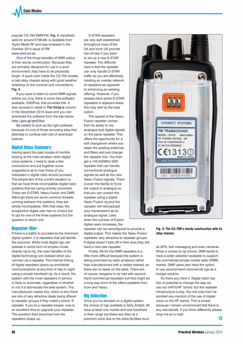
popular CS-700 DMR/FM, Fig. 4, handheld sells for around £199.99, is available from Taylor Made RF and was reviewed in the October 2014 issue of PW.www.tmrf.co.uk
One of the fringe benefi ts of DMR radios is their sturdy construction. Because they are primarily designed for use in a work environment, they have to be physically tough. A quick look inside the CS-700 reveals a cast alloy chassis along with good weather shielding on the controls and connections, Fig. 5.
If you want to listen to some DMR signals before you buy, there is some free software available, DSDPlus, that provides this. It was covered in detail in Tim Kirby’s column in the December 2014 issue and you can download the software from the site below.http://goo.gl/qmC0eo
Be careful to pick up the right software because it’s one of those annoying sites that attempts to confuse with lots of download buttons.
Digital Voice SummaryHaving spent the past couple of months looking at the main amateur radio digital voice systems, I need to draw a few conclusions and put together some suggestions as to how those of you interested in digital radio should proceed. The simple fact of the current situation is that we have three incompatible digital radio systems that are being actively promoted. These are D-STAR, Yaesu Fusion and DMR. Although there are some common threads running between the systems, they are wholly incompatible. With that clear, the prospective digital user has no choice but to opt for one of the three systems but the question is which one.
Repeater WarIf there is a battle to succeed as the dominant digital system, it is repeaters that will decide the outcome. While most digital rigs can operate in some form of simplex mode, directly rig-to-rig, the main benefi ts of the digital technology are realised when you connect via a repeater. The internet linking of digital repeaters opens up worldwide communications at any time of day or night using a simple handheld rig. As a result, the system with the most repeaters in service is likely to dominate, regardless of whether or not it is technically the best system. The manufacturers realise this, which is why there are lots of very attractive deals being offered to repeater groups if they install a brand ‘X’ repeater. If you’re a repeater keeper, now is an excellent time to upgrade your repeater. The question then becomes how the repeaters shape up.
D-STAR repeaters are very well established throughout most of the UK and Icom UK provide lots of help if you want to set up a new D-STAR repeater. The diffi culty here is that the repeater can only handle D-STAR traffi c so you are effectively creating an overlay network of repeaters as opposed to enhancing an existing offering. However, if you already have active D-STAR repeaters in adjacent areas this may well be the best option.
The appeal of the Yaesu Fusion repeater comes from its ability to mix analogue and digital signals on the same repeater. This offers the opportunity for a soft changeover where you retain the existing antennas and fi lters and just change the repeater box. You then get a 145/432MHz 50W repeater that can handle conventional analogue signals as well as the new Yaesu Fusion signals. There is even the facility to force the output to analogue so that you can contact the repeater using a digital Yaesu Fusion rig and the repeater will rebroadcast your transmission as an analogue signal. Later, when the number of Fusion digital users increases, the repeater can be reconfi gured to provide a digital output. This makes the Yaesu Fusion repeaters very attractive to repeater groups. If digital doesn’t take off in their area they still have a nice new repeater.
Finally, life for the DMR repeaters is a little more diffi cult because the system is being promoted by radio amateurs rather than manufacturers with a vested interest, so there are no deals on the table. There are, of course, bargains to be had with second-hand commercial repeaters but that might be a long way short of the offers available from Icom and Yaesu.
Rig SelectionOnce you’ve decided on a digital system, the choice of rigs available is fairly limited. All have at least one mobile and one handheld in their range but these are often at a premium price due to the extra facilities such
as GPS, text messaging and even cameras. When it comes to rig choice, DMR tends to have a wider selection available to support the commercial private mobile radio (PMR) market. DMR users also have the option to use second-hand commercial rigs as a budget solution.
So there you have it. Digital radio has lots of potential to change the way we use our VHF/UHF ‘bricks’ but the repeater infrastructure is key. You will note that I’ve avoided any mention of the use of digital voice on the HF bands. This is simply because I remain unconvinced that there is any real benefi t. If you think differently please drop me an e-mail!
Fig. 5: The CS-700’s sturdy construction with its alloy chassis.
36 Data Modes.indd 3836 Data Modes.indd 38 19/11/2014 11:1919/11/2014 11:19
Data Modes with Mike Richards G4WNC [ 7.J] • E-Mail: [email protected]
DMR and UKHASnet Mike Richards G4WNC answers some reader questions about DMR before returning to last month's topic of UKHASnet.
M y recent coverage of digital voice modes seems to have sparked quite a bit of interest and a few queries so
need to tidy up by answering some of the questions that have arisen.
before I continue with UKHASnet, I
Data Stream TS1
Olgttal Voice -DMB The introduction of digital voice systems to the amateur bands brings with it an
Time Slot 1 B B TS1
Time Slot 2 Data Stream
oO LJ LJ
F.,.1: DMR's two-timeslot system.
2.5ms
TS2
27. 5ms 1
11
27. 5ms
Timeslot 1 11 Timeslot 2
1~
TS1
TS2 TS1 TS2 TS1 TS2 TS1 To
Repeater TS2
5ms
Fig. 2: An illustration of the timing of the DMR timeslots.
Synchronisation Speech payload or Speech payload
108-bits signalling 108-bits 48-bits
27.5ms
264-bits
F.,. 3: Here you can see how the bits are allocated within each timeslot.
36
integration of digital and RF technologies with facilities hitherto unavailable to radio amateurs. As a result, I have received several queries from readers trying to understand what is actually happening. I'll try and clarify that here by looking at the transmission format and networking in a bit more detail.
DMB Repeater Transmissions Digital Mobile Radio (DMR) repeaters are very similar to analogue repeaters in having a single input and a single output frequency and are configured to rebroadcast or repeat whatever is received via the input frequency. When in DMR mode, the modulation on the input and output is 4-frequency FSK (4FSK). Within the 4FSK signal there are two timeslots available known as TS1 and TS2 as shown in Fig. 1. The bandwidth of the 4FSK signal is 12.5kHz but you will often see DMR quoted as occupying just 6.25kHz. This is derived from the fact that the 12.5kHz bandwidth carries two independent channels so each one is assumed to occupy half the overall bandwidth or 6.25kHz. When looking at band utilisation, this assumption is correct and should really be called 6.25kHz equivalence. However, when looking at real signal bandwidth, it's inappropriate because the DMR transmission alwcr.Js occupies 12.5kHz of bandwidth even if only one timeslot is in use. The use of two interteaved timeslots means that two entirely separate conversations can take place on the same frequency. Let's take a closer look at how this works.
Data Bate and Time Slots The gross data rate over a DMR 4FSK channel is 9. 6kbps and this is allocated between services a.s shown in Table 1. Here you can see that each digital voice slot has a dedicated forward error correction (FEC) slot that the receiver uses to check and correct errors in the received signal. The control and signalling slot provides a path for the control information necessary to manage the link along with additional network services.
Let's now take a closer look at the timeslots. Each timeslot is 3:lms long and a standard DMR frame comprises two 30ms timeslots that encompass both of the voice channels. While the timeslots are notionally 30ms long, in practice a guard-band is introduced to allow for propagation and power -amplifier delcr.Js. As a result, each timeslot is really 27.5ms long with a 2.5ms guard band between slots, Fig. 2. Mobile units leave the guard band empty but this narrow slot is
Pri.:tica Wireless March 2015
Timeslot 1 3.6kbs
Timeslot 2 3.6kbs
)lro
7.2kbs
Timeslot 1 3.6kbs
Timeslot 2 3.6kbs
Fig. 4: Dual-channel operation is achieved by sending each slot at twice the required data rate and then rebuilding at the receiver.
Table 1
Service Timeslot 1 digitised voice Timeslot 1 forward error correction Timeslot 2 digitised voice Timeslot 2 forward error correction Control and signalling Total data bandwidth
used by the base stations and repeaters as a CACH (Common Announcement CHannel). Let's now go a little deeper and see what's going on inside each timeslot.
Each 27.5ms timeslot has a total length of 264 data bits that comprises two 108-bit payloads and one 48-bit section that's used for synchronisation or embedded signalling, Fig. 3 The 48-bit sync/signalling slot is placed in the centre of each 30ms timeslot and is used to allow the receiver to synchronise quickly. As you can see, each timeslot has 216 payload bits, which just happens to be sufficient to carry 60ms of compressed speech. Here's how that works. Digitised voice needs 2.45kbps + FEC 1.15kbps = 3.6kbps requirement. In comparison, 216-bits every 30ms = 7.2kbps so the channel is conveying the data for each channel alternately at twice the required speed. When the data is stored and reconstructed by the receiver at normal speed (3.6kbps), you have two continuous speech channels. Put in another way, each voice channel is communicated at twice the required rate, stored in the receiver and then played back at standard rate, Fig. 4. This simple technique enables two separate speech paths to coexist on a sing le frequency radio link.
Repeater Networking Most DMR rigs have some form of rotary channel selector knob that has also become a source of confusion. If I use the popular CS-700 as an example, there is a 16-way rotary knob on the top panel. Turning this knob lets you choose between using TS1 or TS2 for local, European, worldwide and other linking. In a conventional analogue rig, this knob
March 2015 Practical Wlralau
Data Bandwidth (kbps) 2.45 1.15 2.45 1.15 2.40 9.6
will switch the rig between frequencies but the function in DMR is totally different. In DMR mode, this knob is simply selecting different routing options that are available on a single radio channel. Switching between TS1 and TS2 tells the rig which timeslot to use for the path to the repeater. The other choices simply tell the repeater how to route your transmission. If you choose TS1 Local, then your transmission will just be repeated locally using TS1. However, if you select TS1 Europe, your transmission will still be broadcast locally but it will also be forwarded via the Internet to all the DMR repeaters that are connected to the Europe Zone, Fig. 5. The same applies to all the other options. In commercial DMR terms, these routings are called talk-groups, which is a much more helpful description.
More on the Channel Control When used on a DMR repeater, the rotary channel selector knob is normally used to switch between the available talk groups for the selected repeater. Selecting the desired repeater is usually accomplished through a menu system, where you can scroll through a number of Zones with each DRM repeater being allocated its own zone. So in my case, I would use the Zone menu to select my local DMR repeater and then use the rotary 'channel' knob to select the way I want my call routed; that is to say Local, Europe, Worldwide and so on.
If you have a DMR rig that supports conventional analogue FM as well as DMR, you st ill need to be able to change frequencies, so let's look at how that is done. It uses the same controls but you will normally find a Zone ca lled Simplex.
Zone selection
Zone 1 DMR
repeater
Zone 2 DMR
repeater
Zone 3 DMR
repeater
Zone 4 Simplex channels
Channel (talk group)
selector
UK
o--Europe
o--World-wide
' . Roaming
UK
a-- Europe
o--World-wide
' Roaming
UK
a-Europe
o--World-wide
' . Roaming
SU20
o--SU21
o--SU22
' SU23
Fig. 5: Zone and talk group switching.
If you select it, you will find that as you rotate the channel knob, you will be stepping through the standard simplex channels.
Code Pklos As you can imagine, programming all the repeaters and talk groups manually could be a very laborious process. The same problem would also apply to commercial users that want to have the same configuration in all their radios. The solution is to use a database system that's known as a Code Plug. In addition to covering the Zone and channel programming, the Code Plug also controls many other features of the rig, including the action to take when a function button is operated.
While it's possible to build your own Code Plug, by far the best method is to use one of the official code plugs. Not only will the official Code Plug include all the UK repeater Zones and channels, it will also provide the correct rig settings to use the UK DMR network. In most cases, the dealer supplying the rig will install the latest Code Plug for you but if you need to install your own, they are available online. As you might expect, Code Plugs are rig specific so if you are installing one yourself, you need the right
37
..J/i. llatll Modes
Code Plug, programming software and a programming lead to connect your rig to the computer. The first stop for Code Plugs is the DMRUK group and they can be found at the URL below www.dmruk.net
In the case of the CS-700, reviewed in the October 2014 issue of PW, the rig comes with the programming lead and Taylor Made RF supply free Code Plugs. Even if your rig was supplied pre-configured, it's useful to have the programming software and lead so that you can adjust the rig's settings to match your operating preferences.


![1996crd107 A High-Performance Reduced-Complexity GMSK ...prescott/kcp/HPRC-GMSK-Demod.pdf · The GMSK demodulator described in [6] is nonlinear, therefore, the overall CIR seen by](https://static.documents.pub/doc/80x56/5e6cc9ff2fc49425e44e5a70/1996crd107-a-high-performance-reduced-complexity-gmsk-prescottkcphprc-gmsk-demodpdf.jpg)


