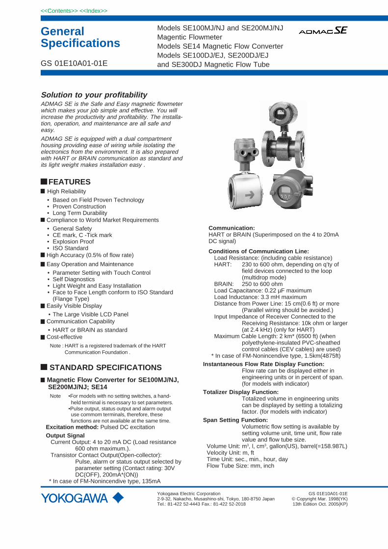
Solution to your profitabilityADMAG SE is the Safe and Easy magnetic flowmeterwhich makes your job simple and effective. You willincrease the productivity and profitability. The installa-tion, operation, and maintenance are all safe andeasy.
ADMAG SE is equipped with a dual compartmenthousing providing ease of wiring while isolating theelectronics from the environment. It is also preparedwith HART or BRAIN communication as standard andits light weight makes installation easy .
FEATURES High Reliability
• Based on Field Proven Technology• Proven Construction• Long Term Durability
Compliance to World Market Requirements
• General Safety• CE mark, C -Tick mark• Explosion Proof• ISO Standard
High Accuracy (0.5% of flow rate)
Easy Operation and Maintenance
• Parameter Setting with Touch Control• Self Diagnostics• Light Weight and Easy Installation• Face to Face Length conform to ISO Standard
(Flange Type) Easily Visible Display
• The Large Visible LCD Panel Communication Capability
• HART or BRAIN as standard Cost-effective
Note : HART is a registered trademark of the HARTCommunication Foundation .
STANDARD SPECIFICATIONS
Magnetic Flow Converter for SE100MJ/NJ,SE200MJ/NJ; SE14Note •For models with no setting switches, a hand-
held terminal is necessary to set parameters.•Pulse output, status output and alarm output use commom terminals, therefore, these functions are not available at the same time.
Excitation method: Pulsed DC excitationOutput Signal Current Output: 4 to 20 mA DC (Load resistance
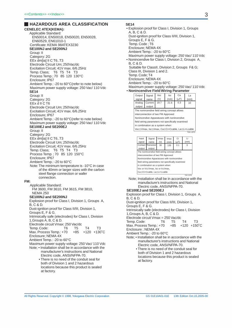
SE14• Explosion proof for Class I, Division 1, Groups
A, B, C & D.Dust-ignition proof for Class II/III, Division 1,Groups E, F & G.
Temp. Code ; T6Enclosure; NEMA 4XAmbient Temp.: -20 to 60°CMaximum power supply voltage: 250 Vac/ 110 Vdc
• Nonincendive for Class I, Division 2, Groups A,B, C & D.
Suitable for ClassII, Division 2, Groups F& G;Class III, Division 1 and 2.Temp. Code; T4Enclosure; NEMA 4XAmbient Temp.: -20 to 60°CMaximum power supply voltage: 250 Vac/ 110 Vdc
Note; Installation shall be in accordance with themanufacture’s instructions and NationalElectric code, ANSI/NFPA-70.
SE100EJ and SE200EJExplosion proof for Class I, Division 1, Groups A,B, C & D.Dust-ignition proof for Class II/III, Division 1,Groups E, F & G.Intrinsically safe (electrodes) for Class I, Division1,Groups A, B, C & D.Electrode circuit Vmax = 250 Vac/dcTemp. Code: T6 T5 T4 T3Max. Process Temp.: +70 +85 +120 +150˚CEnclosure ; NEMA 4XAmbient Temp.: -20 to 60°CNote; • Installation shall be in accordance with the
manufacturer’s instructions and NationalElectric code, ANSI/NFPA-70.
• There is no need of the conduit seal forboth of Division 1 and 2 hazardouslocations because this product is sealedat factory.
HAZARDOUS AREA CLASSIFICATIONCENELEC ATEX(KEMA): Applicable Standard:
Group: IICategory: 2GEEx dm[ia] II C T6..T3Electrode Circuit Um; 250Vac/dcExcitation Circuit; 41V max. 6/6.25HzTemp. Class; T6 T5 T4 T3Process Temp.; 70 85 120 130°CEnclosure; IP67Ambient Temp.: -20 to 60°C(refer to note below)Maximum power supply voltage: 250 Vac/ 110 Vdc
SE14Group: IICategory: 2GEEx d II C T6Electrode Circuit Um; 250Vac/dcExcitation Circuit; 41V max. 6/6.25HzEnclosure; IP67Ambient Temp.: -20 to 60°C(refer to note below)Maximum power supply voltage: 250 Vac/ 110 Vdc
SE100EJ and SE200EJGroup: IICategory: 2GEEx dm[ia] II C T6..T3Electrode Circuit Um; 250Vac/dcExcitation Circuit; 41V max. 6/6.25HzTemp. Class; T6 T5 T4 T3Process Temp. ; 70 85 120 150°CEnclosure; IP67Ambient Temp.: -20 to 60°CNote: The minimum temperature is -10°C in case
of the 40mm or larger sizes with the carbonsteel flange connection or waferconnection.
FM:Applicable Standard:
FM 3600, FM 3610, FM 3615, FM 3810,NEMA 250
SE100NJ and SE200NJExplosion proof for Class I, Division 1, Groups A,B, C & D.Dust-ignition proof for Class II/III, Division 1,Groups E, F & G.Intrinsically safe (electrodes) for Class I, Division1,Groups A, B, C & D.Electrode circuit Vmax: 250 Vac/dcTemp. Code: T6 T5 T4 T3Max. Process Temp.: +70 +85 +120 +130˚CEnclosure; NEMA 4XAmbient Temp.: -20 to 60°CMaximum power supply voltage: 250 Vac/ 110 VdcNote; • Installation shall be in accordance with the
manufacturer’s instructions and NationalElectric code, ANSI/NFPA-70.
• There is no need of the conduit seal forboth of Division 1 and 2 hazardouslocations because this product is sealedat factory.
SE14Ex d II C T6Enclosure: IP67Excitation Circuit: 41V max. 6/6.25HzMaximum power supply voltage: 250 Vac/ 110 Vdc
SE100EJ and SE200EJEx d m ia II C T6..T3Enclosure: IP67Excitation Circuit: 41V max. 6/6.25HzElectrode Circuit Um: 250Vac/dcTemperature
CodeT6T5T4T3
Maximum AmbientTemperature
+60˚C+60˚C+60˚C+60˚C
Maximum ProcessTemperature
+70˚C+85˚C
+120˚C+150˚C
Minimum ProcessTemperature
-40˚C-40˚C-40˚C-40˚C
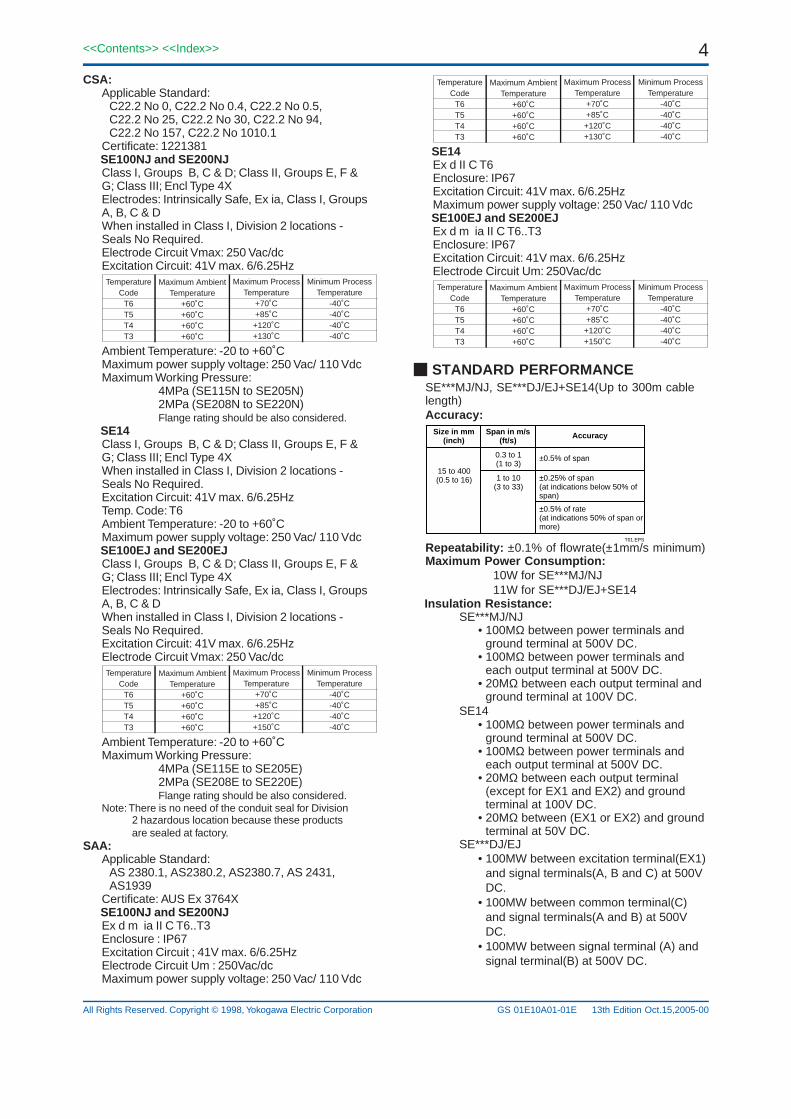
STANDARD PERFORMANCESE***MJ/NJ, SE***DJ/EJ+SE14(Up to 300m cablelength)Accuracy:
Size in mm (inch)
Span in m/s (ft/s)
Accuracy
15 to 400(0.5 to 16)
0.3 to 1(1 to 3)
±0.5% of span
1 to 10(3 to 33)
±0.25% of span(at indications below 50% of span)
±0.5% of rate(at indications 50% of span or more)
T01.EPS
Repeatability: ±0.1% of flowrate(±1mm/s minimum)Maximum Power Consumption:
10W for SE***MJ/NJ11W for SE***DJ/EJ+SE14
Insulation Resistance:SE***MJ/NJ
• 100MΩ between power terminals andground terminal at 500V DC.
• 100MΩ between power terminals andeach output terminal at 500V DC.
• 20MΩ between each output terminal andground terminal at 100V DC.
SE14• 100MΩ between power terminals and
ground terminal at 500V DC.• 100MΩ between power terminals and
each output terminal at 500V DC.• 20MΩ between each output terminal
(except for EX1 and EX2) and groundterminal at 100V DC.
• 20MΩ between (EX1 or EX2) and groundterminal at 50V DC.
SE***DJ/EJ• 100MW between excitation terminal(EX1)
and signal terminals(A, B and C) at 500VDC.
• 100MW between common terminal(C)and signal terminals(A and B) at 500VDC.
• 100MW between signal terminal (A) andsignal terminal(B) at 500V DC.
CSA:Applicable Standard:
C22.2 No 0, C22.2 No 0.4, C22.2 No 0.5,C22.2 No 25, C22.2 No 30, C22.2 No 94,C22.2 No 157, C22.2 No 1010.1
Certificate: 1221381 SE100NJ and SE200NJ
Class I, Groups B, C & D; Class II, Groups E, F &G; Class III; Encl Type 4XElectrodes: Intrinsically Safe, Ex ia, Class I, GroupsA, B, C & DWhen installed in Class I, Division 2 locations -Seals No Required.Electrode Circuit Vmax: 250 Vac/dcExcitation Circuit: 41V max. 6/6.25HzTemperature
CodeT6T5T4T3
Maximum AmbientTemperature
+60˚C+60˚C+60˚C+60˚C
Maximum ProcessTemperature
+70˚C+85˚C+120˚C+130˚C
Minimum ProcessTemperature
-40˚C-40˚C-40˚C-40˚C
Ambient Temperature: -20 to +60˚CMaximum power supply voltage: 250 Vac/ 110 VdcMaximum Working Pressure:
4MPa (SE115N to SE205N)2MPa (SE208N to SE220N)Flange rating should be also considered.
SE14Class I, Groups B, C & D; Class II, Groups E, F &G; Class III; Encl Type 4XWhen installed in Class I, Division 2 locations -Seals No Required.Excitation Circuit: 41V max. 6/6.25HzTemp. Code: T6Ambient Temperature: -20 to +60˚CMaximum power supply voltage: 250 Vac/ 110 Vdc
SE100EJ and SE200EJClass I, Groups B, C & D; Class II, Groups E, F &G; Class III; Encl Type 4XElectrodes: Intrinsically Safe, Ex ia, Class I, GroupsA, B, C & DWhen installed in Class I, Division 2 locations -Seals No Required.Excitation Circuit: 41V max. 6/6.25HzElectrode Circuit Vmax: 250 Vac/dcTemperature
CodeT6T5T4T3
Maximum AmbientTemperature
+60˚C+60˚C+60˚C+60˚C
Maximum ProcessTemperature
+70˚C+85˚C+120˚C+150˚C
Minimum ProcessTemperature
-40˚C-40˚C-40˚C-40˚C
Ambient Temperature: -20 to +60˚CMaximum Working Pressure:
4MPa (SE115E to SE205E)2MPa (SE208E to SE220E)Flange rating should be also considered.
Note: There is no need of the conduit seal for Division2 hazardous location because these productsare sealed at factory.
SAA:Applicable Standard:
AS 2380.1, AS2380.2, AS2380.7, AS 2431,AS1939
Certificate: AUS Ex 3764X SE100NJ and SE200NJ
Ex d m ia II C T6..T3Enclosure : IP67Excitation Circuit ; 41V max. 6/6.25HzElectrode Circuit Um : 250Vac/dcMaximum power supply voltage: 250 Vac/ 110 Vdc
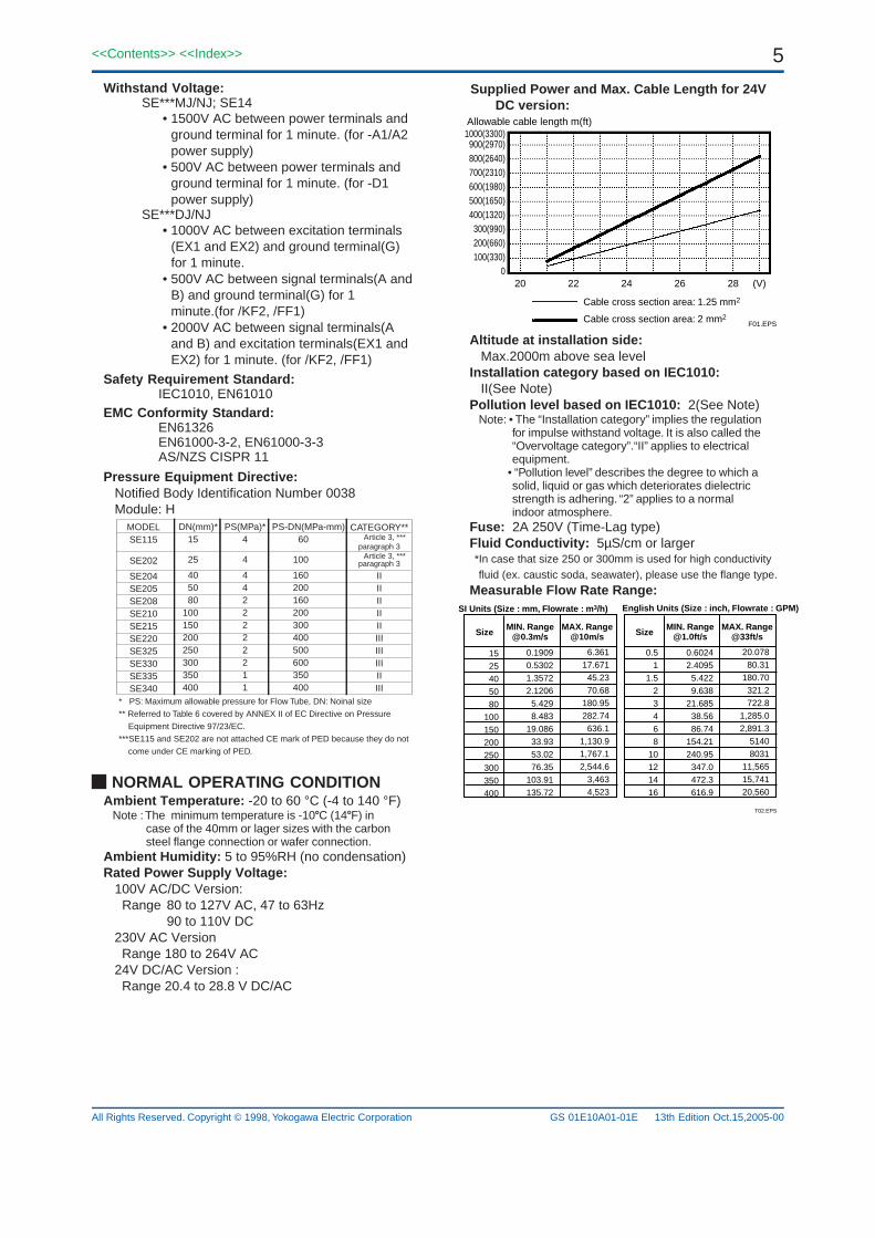
Altitude at installation side: Max.2000m above sea level
Installation category based on IEC1010:II(See Note)
Pollution level based on IEC1010: 2(See Note)Note: • The “Installation category” implies the regulation
for impulse withstand voltage. It is also called the“Overvoltage category”.“II” applies to electricalequipment.
• “Pollution level” describes the degree to which asolid, liquid or gas which deteriorates dielectricstrength is adhering. “2” applies to a normalindoor atmosphere.
Fuse: 2A 250V (Time-Lag type)Fluid Conductivity: 5µS/cm or larger*In case that size 250 or 300mm is used for high conductivityfluid (ex. caustic soda, seawater), please use the flange type.
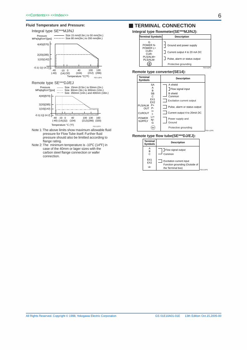
Size 15 mm(0.5in.) to 50 mm(2in.)Size 80 mm(3in.) to 200 mm(8in.)
Remote type SE***DJ/EJ
Temperature °C (°F)
PressureMPakgf/cm2[psi]
Size 15mm (0.5in.) to 50mm (2in.)Size 80mm (3in.) to 300mm (12in.)Size 350mm (14in.) and 400mm (16in.)
440[570]
220[285]
110[142]
-0.1-1[-14.2]-40
(-40)0
(32)-10(14)
100(212)
40(104)
130(266)
160(320)
F02-2.EPS
Note 1: The above limits show maximum allowable fluid pressure for Flow Tube itself. Further fluid pressure should also be limitted according to flange rating.
Note 2: The minimum temperature is -10C (14F) in case of the 40mm or lager sizes with the carbon steel flange connection or wafer connection.
13th Edition Oct.15,2005-00
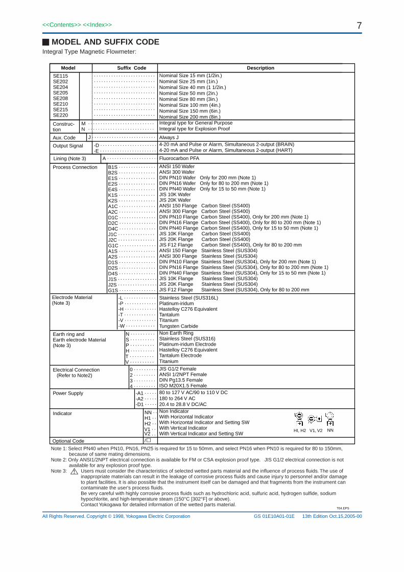
TERMINAL CONNECTIONIntegral type flowmeter(SE***MJ/NJ):
Terminal Symbols Description
GPOWER N-POWER L+
CUR+CUR-
PLS/ALM+PLS/ALM-
Ground and power supply
Current output 4 to 20 mA DC
Pulse, alarm or status output
T03-3.EPS
Protective grounding
Remote type converter(SE14):TerminalSymbols
Description
SAAB
SBC
EX1EX2P+P-I+I-
L/+N/-G
Flow signal input
T03-1.EPS
Protective grounding
A shield
Current output 4 to 20mA DC
Excitation current output
B shieldCommon
Pulse, alarm or status output
Power supply and Ground
PLS/ALM OUT
CUROUT
POWER SUPPLY
Remote type flow tube(SE***DJ/EJ):TerminalSymbols
Description
ABC
EX1EX2
Common
Excitation current inputFunction grounding (Outside of the Terminal box)
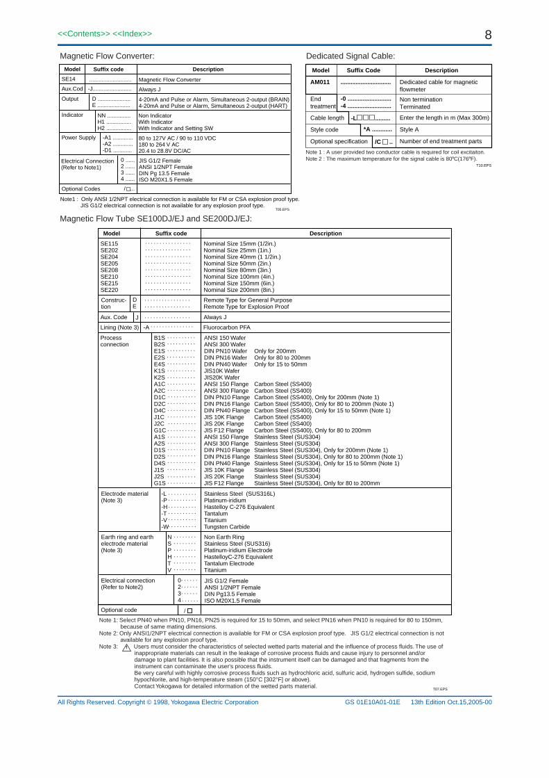
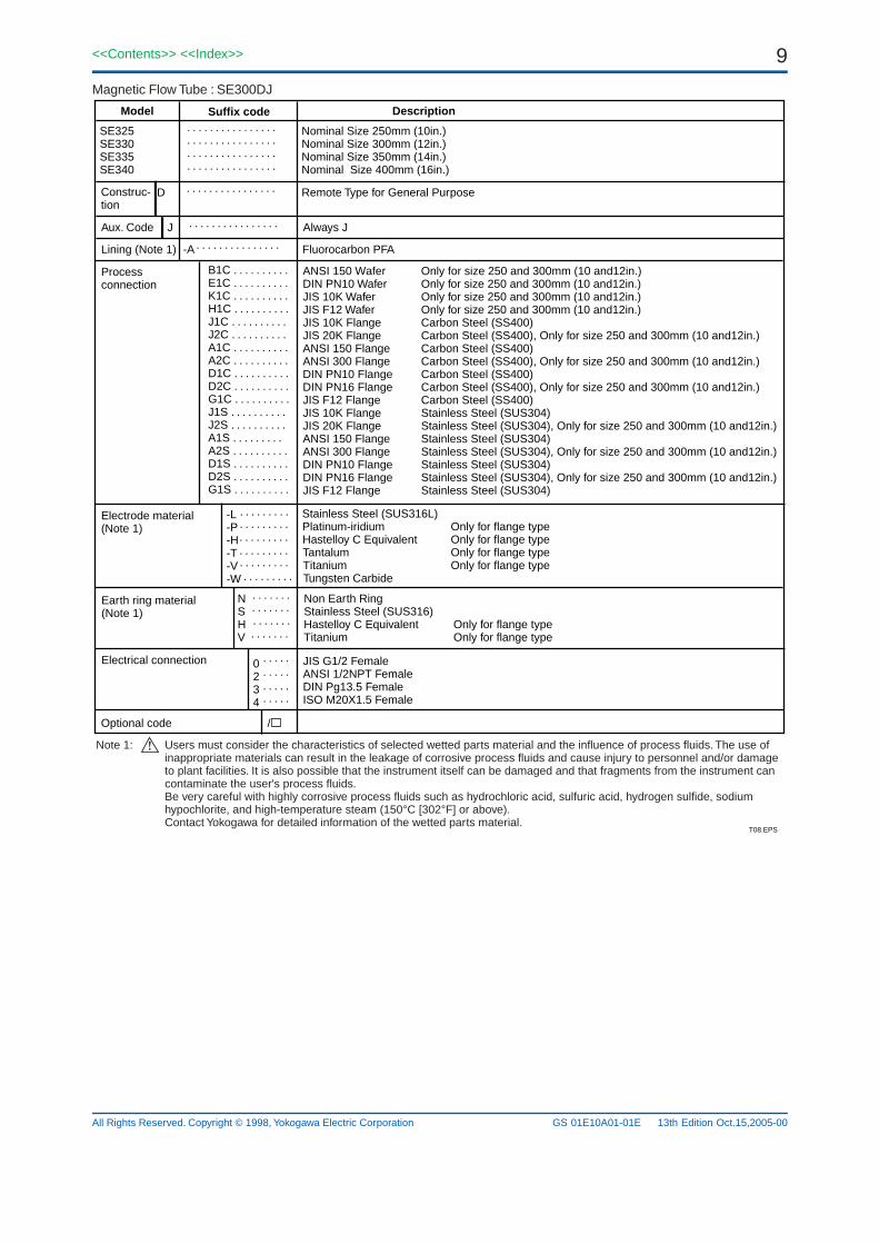
Nominal Size 15 mm (1/2in.)Nominal Size 25 mm (1in.)Nominal Size 40 mm (1 1/2in.)Nominal Size 50 mm (2in.)Nominal Size 80 mm (3in.)Nominal Size 100 mm (4in.)Nominal Size 150 mm (6in.)Nominal Size 200 mm (8in.)Integral type for General PurposeIntegral type for Explosion Proof
Always J4-20 mA and Pulse or Alarm, Simultaneous 2-output (BRAIN)4-20 mA and Pulse or Alarm, Simultaneous 2-output (HART)
Fluorocarbon PFA
ANSI 150 WaferANSI 300 WaferDIN PN10 Wafer Only for 200 mm (Note 1)DIN PN16 Wafer Only for 80 to 200 mm (Note 1)DIN PN40 Wafer Only for 15 to 50 mm (Note 1)JIS 10K WaferJIS 20K WaferANSI 150 Flange Carbon Steel (SS400)ANSI 300 Flange Carbon Steel (SS400)DIN PN10 Flange Carbon Steel (SS400), Only for 200 mm (Note 1)DIN PN16 Flange Carbon Steel (SS400), Only for 80 to 200 mm (Note 1)DIN PN40 Flange Carbon Steel (SS400), Only for 15 to 50 mm (Note 1)JIS 10K Flange Carbon Steel (SS400)JIS 20K Flange Carbon Steel (SS400)JIS F12 Flange Carbon Steel (SS400), Only for 80 to 200 mmANSI 150 Flange Stainless Steel (SUS304)ANSI 300 Flange Stainless Steel (SUS304)DIN PN10 Flange Stainless Steel (SUS304), Only for 200 mm (Note 1)DIN PN16 Flange Stainless Steel (SUS304), Only for 80 to 200 mm (Note 1)DIN PN40 Flange Stainless Steel (SUS304), Only for 15 to 50 mm (Note 1)JIS 10K Flange Stainless Steel (SUS304)JIS 20K Flange Stainless Steel (SUS304)JIS F12 Flange Stainless Steel (SUS304), Only for 80 to 200 mm
JIS G1/2 FemaleANSI 1/2NPT FemaleDIN Pg13.5 FemaleISO M20X1.5 Female80 to 127 V AC/90 to 110 V DC180 to 264 V AC20.4 to 28.8 V DC/ACNon IndicatorWith Horizontal IndicatorWith Horizontal Indicator and Setting SWWith Vertical IndicatorWith Vertical Indicator and Setting SW
Note 1: Select PN40 when PN10, PN16, PN25 is required for 15 to 50mm, and select PN16 when PN10 is required for 80 to 150mm,because of same mating dimensions.
Note 2: Only ANSI1/2NPT electrical connection is available for FM or CSA explosion proof type. JIS G1/2 electrical connection is not available for any explosion proof type.
Note 3: Users must consider the characteristics of selected wetted parts material and the influence of process fluids. The use of inappropriate materials can result in the leakage of corrosive process fluids and cause injury to personnel and/or damage to plant facilities. It is also possible that the instrument itself can be damaged and that fragments from the instrument can contaminate the user's process fluids. Be very careful with highly corrosive process fluids such as hydrochloric acid, sulfuric acid, hydrogen sulfide, sodium hypochlorite, and high-temperature steam (150°C [302°F] or above). Contact Yokogawa for detailed information of the wetted parts material.
Output D .....................E .....................
4-20mA and Pulse or Alarm, Simultaneous 2-output (BRAIN)4-20mA and Pulse or Alarm, Simultaneous 2-output (HART)
Indicator NN ...............H1 ................H2 ................
Non IndicatorWith IndicatorWith Indicator and Setting SW
Power Supply -A1 .............-A2 .............-D1 ............
80 to 127V AC / 90 to 110 VDC180 to 264 V AC20.4 to 28.8V DC/AC
Electrical Connection(Refer to Note1)
0 ......2 ......3 ......4 ......
/ ...
JIS G1/2 FemaleANSI 1/2NPT FemaleDIN Pg 13.5 FemaleISO M20X1.5 Female
Optional Codes
...........................
Note1 : Only ANSI 1/2NPT electrical connection is available for FM or CSA explosion proof type. JIS G1/2 electrical connection is not available for any explosion proof type.
ANSI 150 WaferANSI 300 WaferDIN PN10 Wafer Only for 200mmDIN PN16 Wafer Only for 80 to 200mmDIN PN40 Wafer Only for 15 to 50mmJIS10K WaferJIS20K WaferANSI 150 Flange Carbon Steel (SS400)ANSI 300 Flange Carbon Steel (SS400)DIN PN10 Flange Carbon Steel (SS400), Only for 200mm (Note 1)DIN PN16 Flange Carbon Steel (SS400), Only for 80 to 200mm (Note 1)DIN PN40 Flange Carbon Steel (SS400), Only for 15 to 50mm (Note 1)JIS 10K Flange Carbon Steel (SS400)JIS 20K Flange Carbon Steel (SS400)JIS F12 Flange Carbon Steel (SS400), Only for 80 to 200mmANSI 150 Flange Stainless Steel (SUS304)ANSI 300 Flange Stainless Steel (SUS304)DIN PN10 Flange Stainless Steel (SUS304), Only for 200mm (Note 1)DIN PN16 Flange Stainless Steel (SUS304), Only for 80 to 200mm (Note 1)DIN PN40 Flange Stainless Steel (SUS304), Only for 15 to 50mm (Note 1)JIS 10K Flange Stainless Steel (SUS304)JIS 20K Flange Stainless Steel (SUS304)JIS F12 Flange Stainless Steel (SUS304), Only for 80 to 200mm
Note 1: Select PN40 when PN10, PN16, PN25 is required for 15 to 50mm, and select PN16 when PN10 is required for 80 to 150mm,because of same mating dimensions.
Note 2: Only ANSI1/2NPT electrical connection is available for FM or CSA explosion proof type. JIS G1/2 electrical connection is not available for any explosion proof type.
Note 3: Users must consider the characteristics of selected wetted parts material and the influence of process fluids. The use of inappropriate materials can result in the leakage of corrosive process fluids and cause injury to personnel and/or damage to plant facilities. It is also possible that the instrument itself can be damaged and that fragments from the instrument can contaminate the user's process fluids. Be very careful with highly corrosive process fluids such as hydrochloric acid, sulfuric acid, hydrogen sulfide, sodium hypochlorite, and high-temperature steam (150°C [302°F] or above). Contact Yokogawa for detailed information of the wetted parts material.
Stainless Steel (SUS316L)Platinum-iridium Only for flange typeHastelloy C Equivalent Only for flange typeTantalum Only for flange typeTitanium Only for flange typeTungsten Carbide
JIS G1/2 FemaleANSI 1/2NPT FemaleDIN Pg13.5 FemaleISO M20X1.5 Female
. . . . . . . . . . . . . . .
. . . . . . . . . . . . . . . .
. . . . . . . . . . . . . . . .
. . . . . . . . . . . . . . . .
. . . . . . . . . . . . . . . .
. . . . . . . . . . . . . . . .
. . . . . . . . . . . . . . . .
. . . . . . . . .
. . . . . . . . .
. . . . . . . . .
. . . . . . . . .
. . . . . . .
. . . . . . . . . . . . . .
. . . . . . .
. . . . .
. . . . .
. . . . .
. . . . .
Non Earth RingStainless Steel (SUS316)Hastelloy C Equivalent Only for flange typeTitanium Only for flange type
ANSI 150 Wafer Only for size 250 and 300mm (10 and12in.)DIN PN10 Wafer Only for size 250 and 300mm (10 and12in.)JIS 10K Wafer Only for size 250 and 300mm (10 and12in.)JIS F12 Wafer Only for size 250 and 300mm (10 and12in.)JIS 10K Flange Carbon Steel (SS400)JIS 20K Flange Carbon Steel (SS400), Only for size 250 and 300mm (10 and12in.)ANSI 150 Flange Carbon Steel (SS400)ANSI 300 Flange Carbon Steel (SS400), Only for size 250 and 300mm (10 and12in.)DIN PN10 Flange Carbon Steel (SS400)DIN PN16 Flange Carbon Steel (SS400), Only for size 250 and 300mm (10 and12in.)JIS F12 Flange Carbon Steel (SS400)JIS 10K Flange Stainless Steel (SUS304)JIS 20K Flange Stainless Steel (SUS304), Only for size 250 and 300mm (10 and12in.)ANSI 150 Flange Stainless Steel (SUS304)ANSI 300 Flange Stainless Steel (SUS304), Only for size 250 and 300mm (10 and12in.)DIN PN10 Flange Stainless Steel (SUS304)DIN PN16 Flange Stainless Steel (SUS304), Only for size 250 and 300mm (10 and12in.)JIS F12 Flange Stainless Steel (SUS304)
Note 1: Users must consider the characteristics of selected wetted parts material and the influence of process fluids. The use of inappropriate materials can result in the leakage of corrosive process fluids and cause injury to personnel and/or damage to plant facilities. It is also possible that the instrument itself can be damaged and that fragments from the instrument can contaminate the user's process fluids. Be very careful with highly corrosive process fluids such as hydrochloric acid, sulfuric acid, hydrogen sulfide, sodium hypochlorite, and high-temperature steam (150°C [302°F] or above). Contact Yokogawa for detailed information of the wetted parts material.
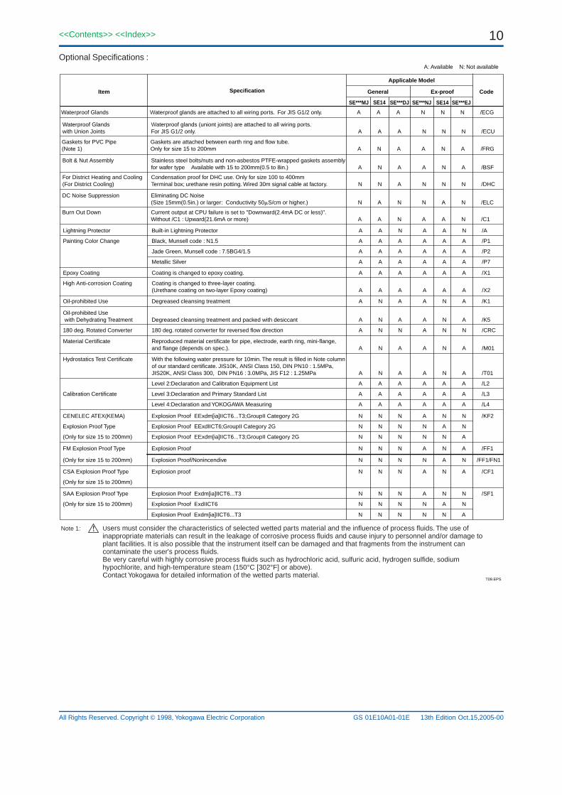
Lightning Protector Built-in Lightning Protector A A N A A N /A
Waterproof Glands Waterproof glands are attached to all wiring ports. For JIS G1/2 only. A A A N N N /ECG
Painting Color Change Black, Munsell code : N1.5 A A A A A A /P1
Jade Green, Munsell code : 7.5BG4/1.5 A A A A A A /P2
Metallic Silver A A A A A A /P7
Level 2:Declaration and Calibration Equipment List A A A A A A /L2
Calibration Certificate Level 3:Declaration and Primary Standard List A A A A A A /L3
Level 4:Declaration and YOKOGAWA Measuring A A A A A A /L4
CENELEC ATEX(KEMA) Explosion Proof EExdm[ia]IICT6...T3;GroupII Category 2G N N N A N N /KF2
FM Explosion Proof Type Explosion Proof N N N A N A /FF1
CSA Explosion Proof Type Explosion proof N N N A N A /CF1
(Only for size 15 to 200mm) Explosion Proof/Nonincendive N N N N A N /FF1/FN1
(Only for size 15 to 200mm)
Explosion Proof Type Explosion Proof EExdIICT6;GroupII Category 2G N N N N A N
(Only for size 15 to 200mm) Explosion Proof EExdm[ia]IICT6...T3;GroupII Category 2G N N N N N A
SAA Explosion Proof Type Explosion Proof Exdm[ia]IICT6...T3 N N N A N N /SF1
(Only for size 15 to 200mm) Explosion Proof ExdIICT6 N N N N A N
Explosion Proof Exdm[ia]IICT6...T3 N N N N N A
Epoxy Coating Coating is changed to epoxy coating. A A A A A A /X1
Oil-prohibited Use Degreased cleansing treatment A N A A N A /K1
180 deg. Rotated Converter 180 deg. rotated converter for reversed flow direction A N N A N N /CRC
Material Certificate Reproduced material certificate for pipe, electrode, earth ring, mini-flange,and flange (depends on spec.). A N A A N A /M01
Hydrostatics Test Certificate With the following water pressure for 10min. The result is filled in Note columnof our standard certificate. JIS10K, ANSI Class 150, DIN PN10 : 1.5MPa,JIS20K, ANSI Class 300, DIN PN16 : 3.0MPa, JIS F12 : 1.25MPa A N A A N A /T01
Oil-prohibited Use with Dehydrating Treatment Degreased cleansing treatment and packed with desiccant A N A A N A /K5
High Anti-corrosion Coating Coating is changed to three-layer coating.(Urethane coating on two-layer Epoxy coating) A A A A A A /X2
Waterproof Glands Waterproof glands (uniont joints) are attached to all wiring ports. with Union Joints For JIS G1/2 only. A A A N N N /ECU
Bolt & Nut Assembly Stainless steel bolts/nuts and non-asbestos PTFE-wrapped gaskets assemblyfor wafer type Available with 15 to 200mm(0.5 to 8in.) A N A A N A /BSF
For District Heating and Cooling Condensation proof for DHC use. Only for size 100 to 400mm(For District Cooling) Terminal box; urethane resin potting. Wired 30m signal cable at factory. N N A N N N /DHC
DC Noise Suppression Eliminating DC Noise (Size 15mm(0.5in.) or larger: Conductivity 50S/cm or higher.) N A N N A N /ELC
Burn Out Down Current output at CPU failure is set to "Downward(2.4mA DC or less)".Without /C1 : Upward(21.6mA or more) A A N A A N /C1
Gaskets for PVC Pipe Gaskets are attached between earth ring and flow tube.(Note 1) Only for size 15 to 200mm A N A A N A /FRG
Note 1: Users must consider the characteristics of selected wetted parts material and the influence of process fluids. The use of inappropriate materials can result in the leakage of corrosive process fluids and cause injury to personnel and/or damage to plant facilities. It is also possible that the instrument itself can be damaged and that fragments from the instrument can contaminate the user's process fluids. Be very careful with highly corrosive process fluids such as hydrochloric acid, sulfuric acid, hydrogen sulfide, sodium hypochlorite, and high-temperature steam (150°C [302°F] or above). Contact Yokogawa for detailed information of the wetted parts material.
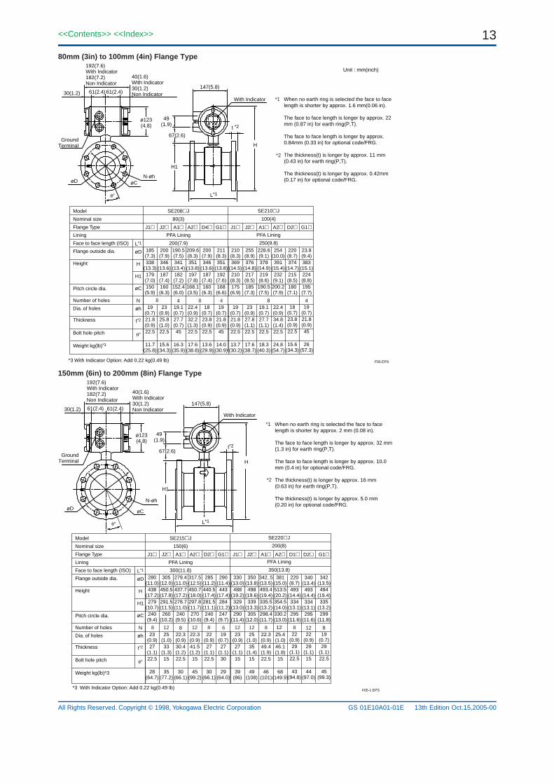
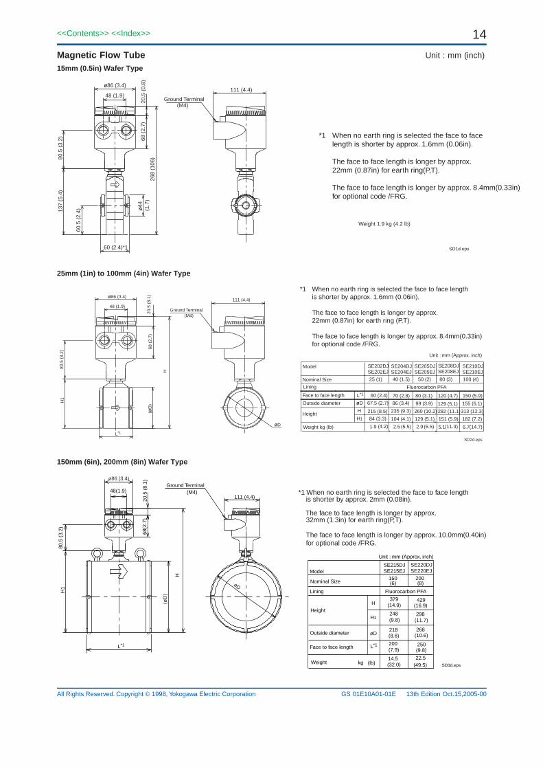
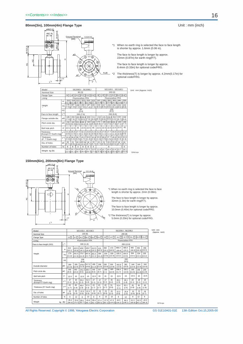
*1 When no earth ring is selected the face to face length is shorter by approx. 1.6mm (0.06in).
The face to face length is longer by approx. 22mm (0.87in) for earth ring(P,T).
The face to face length is longer by approx. 8.4mm(0.33in)for optional code /FRG.
(M4)
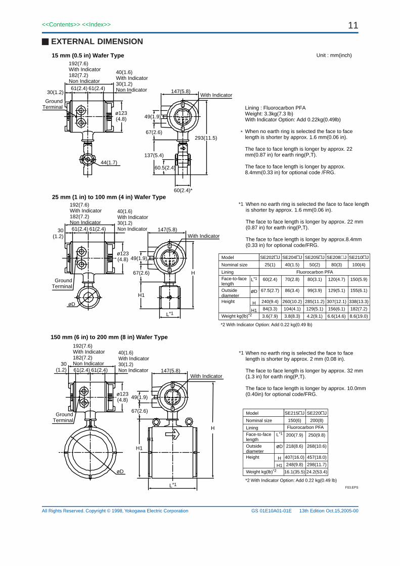
25mm (1in) to 100mm (4in) Wafer Type
Face to face length
Nominal Size
Model
(14.7)(11.3)(6.5)(5.5) (4.2)1.9
Unit : mm (Approx. inch)
100 (4)80 (3)50 (2)40 (1.5)25 (1)
6.75.12.92.5Weight kg (lb)
182 (7.2)151 (5.9)129 (5.1)104 (4.1)84 (3.3)
155 (6.1)129 (5.1)99 (3.9)86 (3.4)67.5 (2.7)
235 (9.3) 313 (12.3)282 (11.1)260 (10.2)215 (8.5)
150 (5.9)120 (4.7)80 (3.1)70 (2.8)60 (2.4)
SE202DJSE202EJ
H1
H
L*1
(M4)
68 (
2.7)
20.5
(8.
1)
H
H1
L*1
111 (4.4)
48 (1.9)
80.5
(3.
2)
Lining
Outside diameter
Height
Fluorocarbon PFA
ø86 (3.4)
(øD
)
øD
øD
Ground Terminal
SD2d.eps
*1 When no earth ring is selected the face to face lengthis shorter by approx. 1.6mm (0.06in).
The face to face length is longer by approx. 22mm (0.87in) for earth ring (P,T).
The face to face length is longer by approx. 8.4mm(0.33in)for optional code /FRG.
SE204DJSE204EJ
SE205DJSE205EJ
SE208DJSE208EJ
SE210DJSE210EJ
150mm (6in), 200mm (8in) Wafer Type
Unit : mm (Approx. inch)
Model
Nominal Size
Weight
Ground Terminal(M4)
L*1 250200
H
H1
SE215DJSE215EJ
150
SE220DJSE220EJ
200
14.5
248
379
298
429
218 268
22.5(32.0) (49.5) kg (lb)
H
H1
80.5
(3.
2)
48(1.9)111 (4.4)
20.5
(8.
1)68
(2.7
)
Lining
Height
(6) (8)
Outside diameter
Face to face length
(14.9)
(9.8)
(16.9)
(11.7)
(8.6) (10.6)
(7.9) (9.8)
Fluorocarbon PFA
øD
ø86 (3.4)
(øD
)
øD
SD3d.eps
*1 When no earth ring is selected the face to face length is shorter by approx. 2mm (0.08in). The face to face length is longer by approx. 32mm (1.3in) for earth ring(P,T).
The face to face length is longer by approx. 10.0mm(0.40in) for optional code /FRG.
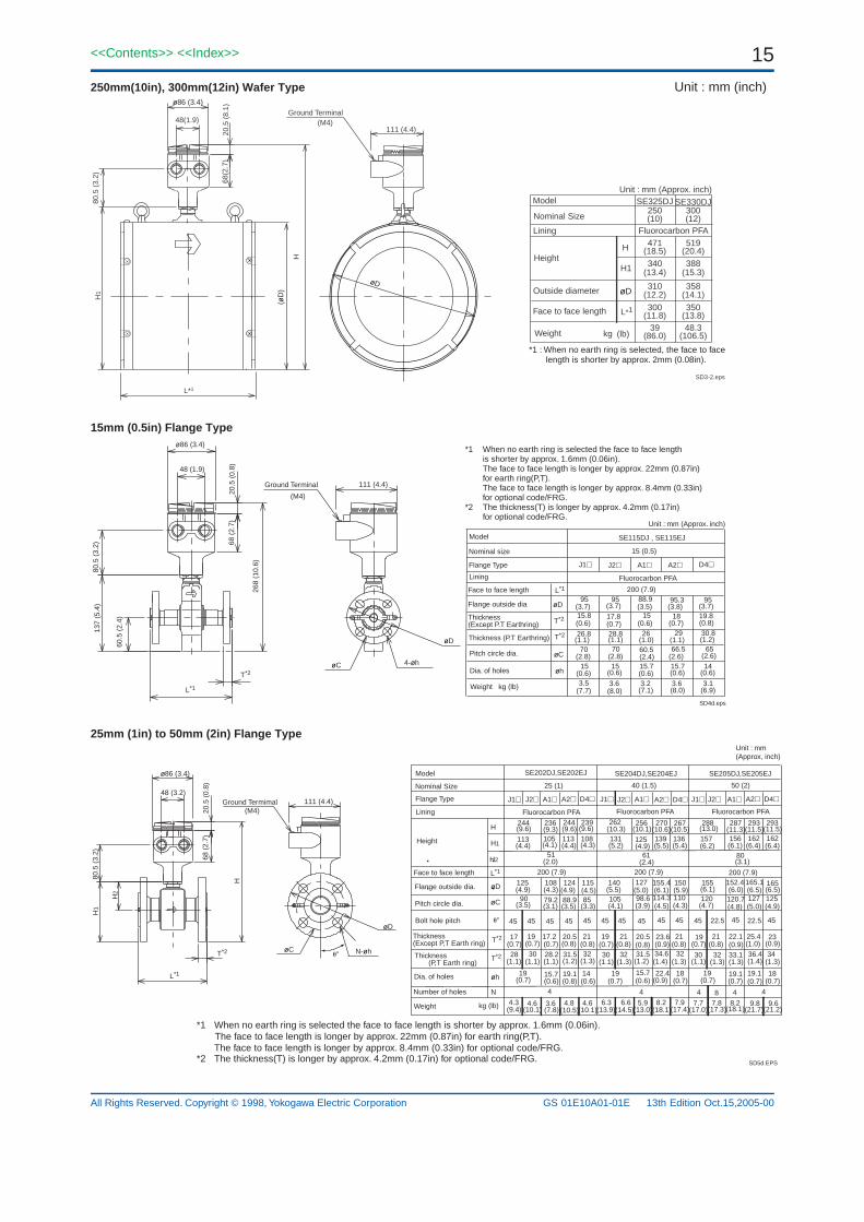
250mm(10in), 300mm(12in) Wafer Type Unit : mm (inch)
SD3-2.eps
øD
Ground Terminal(M4)
111 (4.4)
80.5
(3.
2)
48(1.9)
20.5
(8.
1)68
(2.7
)
ø86 (3.4)
L*1
H
H1
(øD
)
Unit : mm (Approx. inch)Model
Nominal Size
Weight
L*1350300
H
H1
SE325DJ250
SE330DJ300
39
340
471
388
519
310 358
48.3(86.0) (106.5) kg (lb)
Lining
Height
(10) (12)
Outside diameter
Face to face length
(18.5)
(13.4)
(20.4)
(15.3)
(12.2) (14.1)
(11.8) (13.8)
Fluorocarbon PFA
øD
*1 : When no earth ring is selected, the face to face length is shorter by approx. 2mm (0.08in).
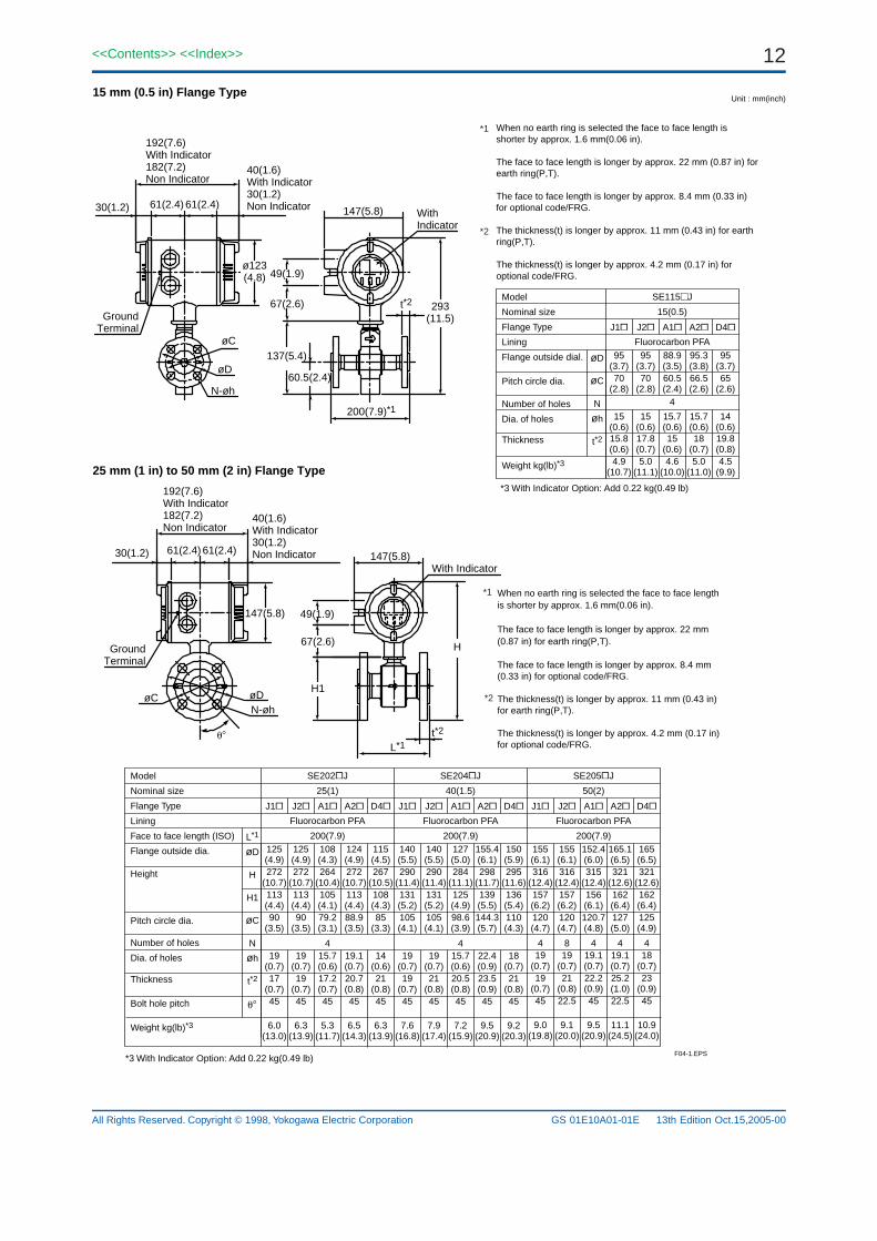
15mm (0.5in) Flange Type
Face to face length
(6.9)(8.0)(7.1)(8.0)(7.7)
200 (7.9)
(M4)
30.8292628.826.8T*2
3.13.63.23.63.5
15.8 17.8 15
66.560.57070
18
95 95 88.9 95.3
15 15 15.7 15.7
T*2
øh
95
19.8
65
14
J1 J2 A1 A2 D4
L*1268
(10.
6)
137
(5.4
)80
.5 (
3.2)
48 (1.9)
111 (4.4)
20.5
(0.
8)68
(2.
7)
L*1
T*2
60.5
(2.
4)
Unit : mm (Approx. inch)
(3.7)
(0.6)
(1.1)
(2.8)
(0.6)
(3.7)
(0.7)
(1.1)
(2.8)
(0.6)
(3.5)
(0.6)
(1.0)
(2.4)
(0.6)
(3.8)
(0.7)
(1.1)
(2.6)
(0.6)
(3.7)
(0.8)
(1.2)
(2.6)
(0.6)
Flange outside dia
Dia. of holes
Pitch circle dia.
Thickness (Except P.T Earthring)
Weight kg (lb)
Lining
Flange Type
Ground Terminal
Thickness (P.T Earthring)
Fluorocarbon PFA
Nominal size
Model SE115DJ , SE115EJ
15 (0.5)
4-øh
øD
øC
ø86 (3.4)
øC
øD
SD4d.eps
*1 When no earth ring is selected the face to face length is shorter by approx. 1.6mm (0.06in).The face to face length is longer by approx. 22mm (0.87in)for earth ring(P,T).The face to face length is longer by approx. 8.4mm (0.33in)for optional code/FRG.
*2 The thickness(T) is longer by approx. 4.2mm (0.17in)for optional code/FRG.
25mm (1in) to 50mm (2in) Flange Type
Ground Termimal
80.5
(3.
2)
48 (3.2)111 (4.4)
20.5
(0.
8)68
(2.
7)
H1
H2
H
L*1
T*2
SD5d.EPS
N-øhøC
øD
ø86 (3.4)
*1 When no earth ring is selected the face to face length is shorter by approx. 1.6mm (0.06in). The face to face length is longer by approx. 22mm (0.87in) for earth ring(P,T).
The face to face length is longer by approx. 8.4mm (0.33in) for optional code/FRG.*2 The thickness(T) is longer by approx. 4.2mm (0.17in) for optional code/FRG.
*1 When no earth ring is selected the face to face length is shorter by approx. 2mm (0.08in). The face to face length is longer by approx. 32mm (1.3in) for earth ring(P,T). The face to face length is longer by approx. 10.0mm (0.40in) for optional code/FRG.
*2 The thickness(T) is longer by approx. 5.0mm (0.20in) for optional code/FRG.
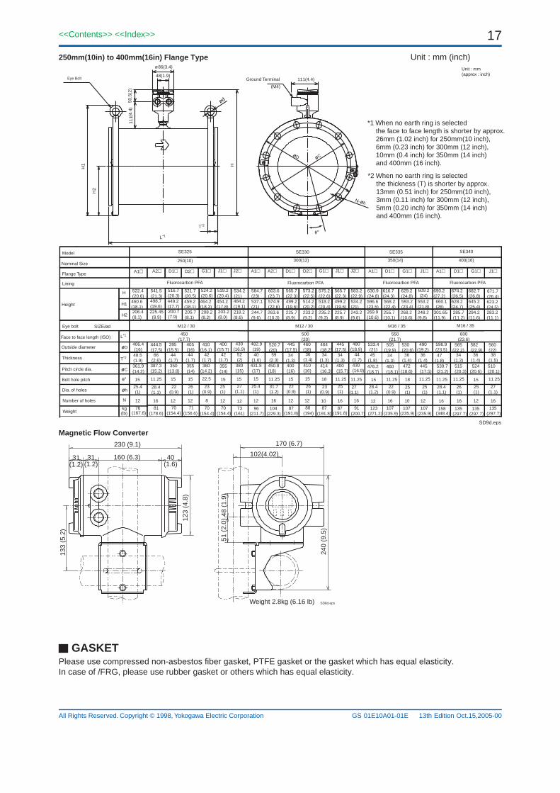
250mm(10in) to 400mm(16in) Flange Type Unit : mm (inch)
L*1
T*2
Ground TerminalEye Bolt
(M4)H
1
H2
48(1.9)
86(3.4)ø
H
111(4.4)
111(
4.4)
50.5
(2)
øhN-
øC
ød
øD
*1 When no earth ring is selected the face to face length is shorter by approx. 26mm (1.02 inch) for 250mm(10 inch), 6mm (0.23 inch) for 300mm (12 inch), 10mm (0.4 inch) for 350mm (14 inch) and 400mm (16 inch).
*2 When no earth ring is selected the thickness (T) is shorter by approx. 13mm (0.51 inch) for 250mm(10 inch), 3mm (0.11 inch) for 300mm (12 inch), 5mm (0.20 inch) for 350mm (14 inch) and 400mm (16 inch).
GASKETPlease use compressed non-asbestos fiber gasket, PTFE gasket or the gasket which has equal elasticity.In case of /FRG, please use rubber gasket or others which has equal elasticity.
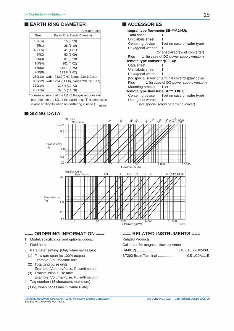
* Please ensure that the I.D. of the gasket does not protrude into the I.D. of the earth ring. (This dimension is also applied to when no earth ring is used.)
ACCESSORIESIntegral type flowmeter(SE***MJ/NJ): Data sheet 1
Unit labels sheet 1Centering device 1set (in case of wafer type)Hexagonal wrench 1 (for special screw of converter)Plug 1 (in case of DC power supply version)
Remote type converter(SE14):Data sheet 1Unit labels sheet 1Hexagonal wrench 1(for special screw of terminal cover/display cover.)Plug 1 (in case of DC power supply version)Mounting bracket 1set
Remote type flow tube(SE***DJ/EJ):Centering device 1set (in case of wafer type)Hexagonal wrench 1
(for special screw of terminal cover)
Subject to change without notice.13th Edition Oct.15,2005-00