16
Global Trigger Upgrades for SLHC Vienna, Global Trigger Group A.Taurok , C.-E. Wulz SLHC Workshop, FNAL, 19 Nov. 2008
| Date post: | 24-Dec-2015 |
| Category: |
Documents |
| Upload: | samuel-clement-atkins |
| View: | 218 times |
| Download: | 0 times |
Global Trigger Upgrades for SLHC
Vienna, Global Trigger GroupA.Taurok, C.-E. Wulz
SLHC Workshop, FNAL, 19 Nov. 2008
19 Nov. 2008 A. Taurok, C.-E. Wulz 2
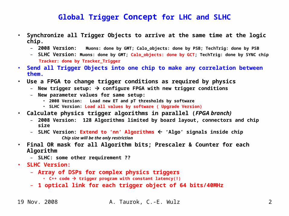
Global Trigger Concept for LHC and SLHC
• Synchronize all Trigger Objects to arrive at the same time at the logic chip.– 2008 Version: Muons: done by GMT; Calo_objects: done by PSB; TechTrig: done by PSB
– SLHC Version: Muons: done by GMT; Calo_objects: done by GCT; TechTrig: done by SYNC chip
Tracker: done by Tracker_Trigger
• Send all Trigger Objects into one chip to make any correlation between them. • Use a FPGA to change trigger conditions as required by physics
– New trigger setup: configure FPGA with new trigger conditions– New parameter values for same setup:
• 2008 Version: Load new ET and pT thresholds by software• SLHC Version: Load all values by software ( Upgrade Version)
• Calculate physics trigger algorithms in parallel (FPGA branch)– 2008 Version: 128 Algorithms limited by board layout, connectors and chip size– SLHC Version: Extend to ‘nn’ Algorithms ‘Algo’ signals inside chip
Chip size will be the only restriction
• Final OR mask for all Algorithm bits; Prescaler & Counter for each Algorithm– SLHC: some other requirement ??
• SLHC Version: – Array of DSPs for complex physics triggers
• C++ code trigger program with constant latency(!)
– 1 optical link for each trigger object of 64 bits/40MHz
19 Nov. 2008 A. Taurok, C.-E. Wulz 3
CA
EN
VM
E
CO
NT
RO
LL
ER
FR
EE
VM
E
FR
EE
VM
E
L1A
_OU
TL
1A
1 2 3 4 5 6 7 8 9 10 11 12 13 14 15 16 17 18 19 20 21
L1A
_OU
T
TC
S
PS
B
PS
B
PS
B
PS
B
PS
B
PS
B
PS
B
FD
L
GT
L
spar
e
TIM
GT
FE
GM
T
PC
: R
UN
Co
ntr
ol
Det
ecto
r s
ub
syst
ems
aTT
S D
AQ
AP
V-E
MU
LA
TO
RS
STA
TU
S SI
GN
AL
S
TE
CH
NIC
AL
T
RIG
GE
R S
IGN
AL
S
4IE
G, 4
EG
, 4JE
T,
4fJE
T
4TA
U-J
ET
, ET
*, J
etN
r,
TO
TE
M
CL
K, O
RB
IT
TT
C -
GP
S-T
IME
S-lin
ks:
DA
Q, E
VM
(ET
*=to
tal E
T, H
T, M
ET
)
8 R
PC
muo
ns4
DT
muo
ns4
CSC
muo
ns
MIP
/QU
IET
bit
s
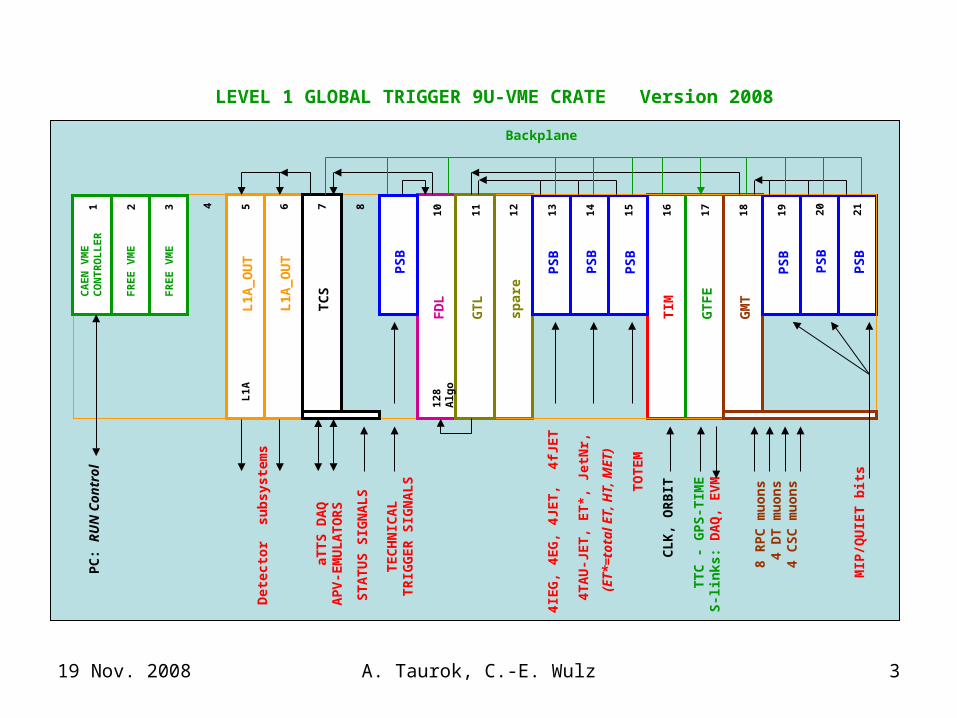
LEVEL 1 GLOBAL TRIGGER 9U-VME CRATE Version 2008
128
Alg
o
Backplane

19 Nov. 2008 A. Taurok, C.-E. Wulz 4
CMS Level1 Global Trigger scheme
FDL
GTL
GTL
128 Algo
GMT
PSBGCT
Syncdelay
Syncdelay
REC
COND ALGO
PSBSyncdelay
Technical Triggers
FDL chip
GTL
COND chip
GMTOptical links
GCT
Syncdelay
Syncdelay
SYNCSyncdelay
‘Conditions’
COND chip
nn Algo
(and,or,
not)
FPGA:Standard Conditions
- FPGA: DSPs (XC5V100T)
Totem, Castor, ZDC, …
TrackerTrigger
Syncdelay
Prescalers&
Trigger Counters
FinalOR
FinalOR
COND ALGO
LHC
SLHC
Tracker ‘Conditions’ Prescalers&
Trigger Counters
Totem, Castor, ZDC, …

19 Nov. 2008 A. Taurok, C.-E. Wulz 5
Input to Global Trigger
•Global Calorimeter Trigger (GCT): possible reduction of trigger data•4 eg, 4 ieg 4 eg with ISOLATION bit•4 central jets, 4 forward jets 4…6 jets•4 tau jets•total_ET, HT apply set of thresholds in GCT
and send resulting bits to FDL chip
•missing_ET
•jet numbers•More than 4 objects per type: 5 or 6 (?) Simulation for SLHC
•Global Muon Trigger (GMT):•4 muons pmip, iso, charge, quality
•Tracker Trigger:•Tracks/jets with and COND chips•‘Conditions’ calculated in Tracker Trigger FDL chip
19 Nov. 2008 A. Taurok, C.-E. Wulz 6
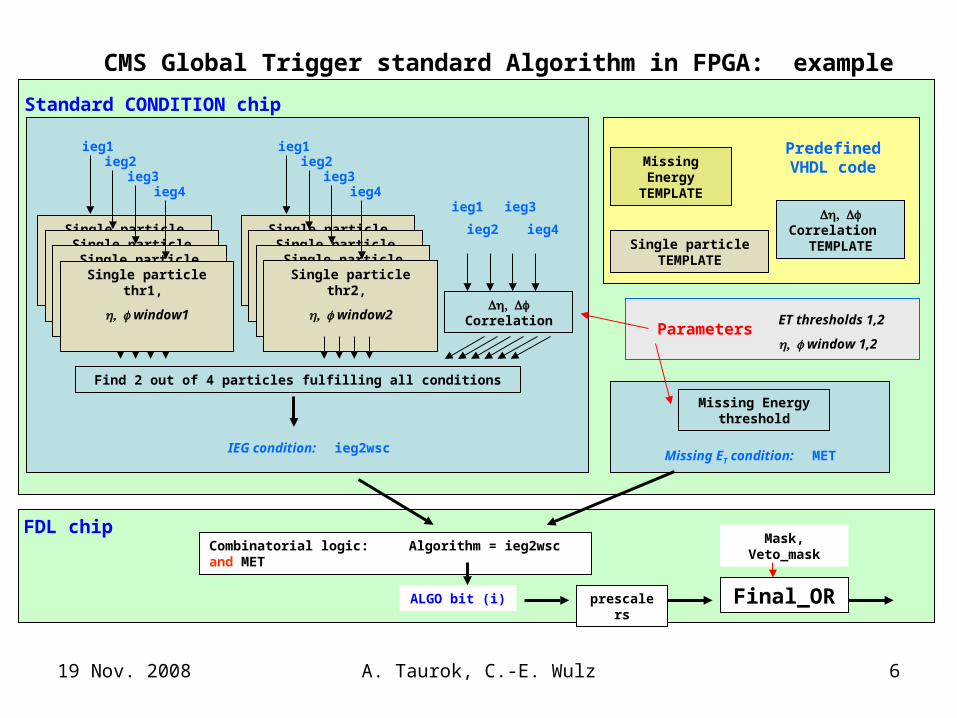
Correlation TEMPLATE
Missing Energy TEMPLATE
Predefined VHDL code
Single particle TEMPLATE
ParametersET thresholds 1,2
window 1,2
Missing Energy threshold
Correlation
ieg1
ieg2
ieg3
ieg4
Find 2 out of 4 particles fulfilling all conditions
IEG condition: ieg2wsc
Combinatorial logic: Algorithm = ieg2wsc and MET
Missing ET condition: MET
ALGO bit (i) Final_OR
Single particle thr2,
window2Single particle thr2,
window2Single particle thr2,
window2Single particle thr2,
window2
Single particle thr1,
window1Single particle thr1,
window1Single particle thr1,
window1Single particle thr1,
window1
ieg1
ieg4
ieg2ieg3
ieg1
ieg4
ieg2ieg3
CMS Global Trigger standard Algorithm in FPGA: example
Mask, Veto_mask
prescalers
Standard CONDITION chip
FDL chip

19 Nov. 2008 A. Taurok, C.-E. Wulz 7
CONDITION chip with DSP array, RISCs
DSPCondition program
Trigger objects(GCT, GMT, TrackerTr…) Parameters
Condition bit
Parallel or tree structures
DSP DSP DSP
DSP
DSPDSPDSP
Trigger objects Trigger objects
Latency Latency
Algorithm logic in FDL chip Algorithm logic in FDL chip
Constraints:• # of Conditions # of DSPs• # of instructions latency limit• Keep pipeline structure
Latency = # of instructions
Hardwired logic*
*) if DSPs are implemented in FPGA
XC5VFX100T: 256 DSP48E(550MHz), 4 Ethernet MAC,3 PCIexpress end points, 16 GTX RocketIO (6.5Gb/s)680 IO (1.25Gb/s LVDS)
Condition bitCondition bit
OR

19 Nov. 2008 A. Taurok, C.-E. Wulz 8
Global Trigger board for SLHC (‘Single board’ option)
2 sets of opt. rcvers
RX:Serial parallel
COND_logicor
DSP array
Ethernet IPL1A_daq + Serial TX
LVDS
FDL chip
nn Algo
(and,or,
not)
FinalOR
COND chip
SYNC Chip
DAQ chip
L1A_daq + Serial TX
GCT: 5 ...GMT: 2Tracker: ~2 ..
Parallel data
LVDS
Ethernet IP
ControlCPU
ControlCPU
Ethernet IP
Ethernet IP
Trigger Counters
Pre
scal
ers
Spy_mem‘s &Ringbuffers
Spy_mem‘s &Ringbuffers
Event builder CMS - DAQ
LVDS LVDS Condition bits
Ethernet IO
Synccircuits
Condition bits
CLK, BCRES, ...
LVDSTIMINGcircuits
LVDS
CLK, BCRES, ..

19 Nov. 2008 A. Taurok, C.-E. Wulz 9
Option with Custom MTCA backplaneGT logic with AMC single width module from Imperial College & LosAlamos Lab.
GCT 2 copies of7 quadruplets à 64 bits 12/16
12/16
FPGA72x72
SWITCH
20
20
16
16
12/16
12/16
FPGA72x72
SWITCH
20
20
16
16
CONDITION CHIP 1+2
ALGO + FinOR (FDL)
12/16
12/16
FPGA72x72
SWITCH
20
20
16
16
7
TrackerTrigger2 copies of≤5 links à 64 bits
5
AMC single width (h=73.8 mm, l=181.5 mm)
128 Technical Trigger bitsfrom Conversion crate
2
12/16
12/16
FPGA72x72
SWITCH
20
20
16
164
Central Trigger Control
8FinalOR
32x 8 (L1A, 5Bgo…)
1
Custom Backplane
L1A..directly or via Big_Conversion boards to TTC system
Readout Board as double width AMC withSLINK mezzanine board
Readout data
PartitionSTATUS from2 Big_Conversion boards
2
CMS_DAQ
512 Condition bits
8
3.2 Gbps optical links
3.2 Gbps backplane links
NOT shown/defined:•Global Muon Trigger•Readout board with SLINK•LVDS/Serial Conversion crate
1Readout Board
1Readout Board
1Readout Board

19 Nov. 2008 A. Taurok, C.-E. Wulz 10
MTCA options: 40 MHz LVDS to Serial Conversion AMC modules (Vienna)
Serial link(1.6 Gbps required)
FPGA
8 RJ45 (59.2 x 25.5 mm)
SMALL_CONVERSION card single width, full size (w=73.8 mm, l=181.5 mm, h=28.95 mm)
32 bits
CONVERSION card double width,full size (w=148.8 mm, l=181.5 mm, h=28.95 mm)
FPGA
64 bits/40MHz
Serial link(3.2 Gbps required)
INPUT MODEOUTPUT MODE
INPUT MODE
Serial link(1.6 Gbps required)
FPGA
32 bits
OUTPUT MODE
Global Trigger: 128 Technical Trigger bits 4 SMALL_CONVERSION boards (INPUT mode)
Central Trigger Control: 40x4 STATUS bits 5 SMALL_CONVERSION boards (INPUT mode) 8x4 EMULATOR CONTROL signals 1 SMALL_CONVERSION boards (OUTPUT mode)32x8 L1A+BGo signals 8 SMALL_CONVERSION boards (OUTPUT mode)
Global Trigger: 128 Technical Trigger bits 2 CONVERSION boards (INPUT mode)
Central Trigger Control: 32x4 STATUS bits 2 CONVERSION boards (INPUT mode) 8x4x2 EMULATOR CTRL+STATUS 1 CONVERSION boards (I/O mode)32x8 L1A+BGo signals 4 CONVERSION boards (OUTPUT mode)
Many boards!! No front panel serial links
9 boards Serial links (3.2 Gbps) on front panel
FPGA
I/O MODE
64 bits/40MHz
Serial link(3.2 Gbps required)
Synchronization, Monitoring
FPGA
64 bits/40MHz
Serial link(3.2 Gbps required)
Monitoring
LC duplex
19 Nov. 2008 A. Taurok, C.-E. Wulz 11
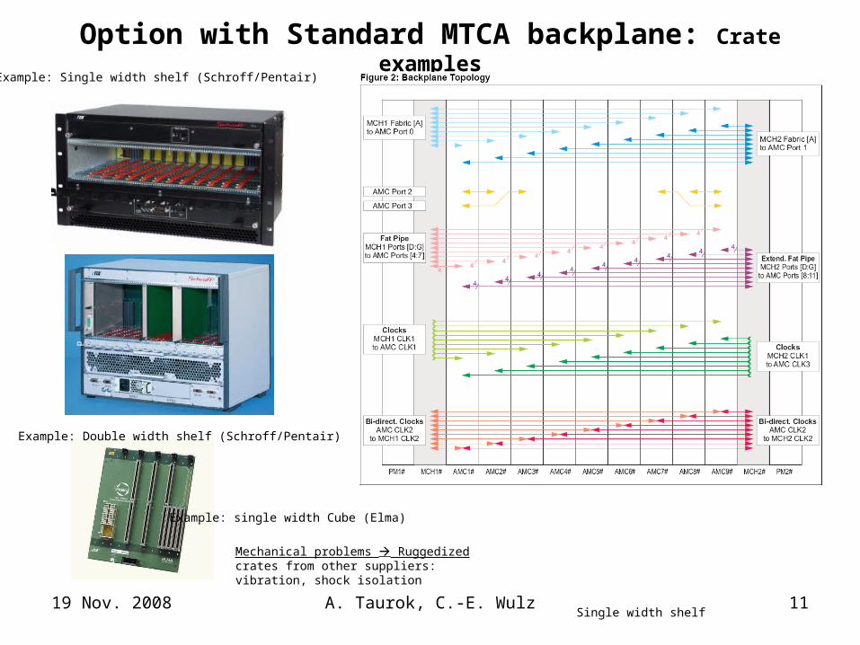
Option with Standard MTCA backplane: Crate examples
Single width shelf
Example: Single width shelf (Schroff/Pentair)
Mechanical problems Ruggedized crates from other suppliers: vibration, shock isolation
Example: single width Cube (Elma)
Example: Double width shelf (Schroff/Pentair)

19 Nov. 2008 A. Taurok, C.-E. Wulz 12
Option with Standard MTCA backplane: Example of standard MCH (MTCA carrier hub) module
Tundra TSi578 (Tundra Web page)RapidIO 1.25, 2.5, and 3.125 Gbits/s per port
NAT-MCH (www.nateurope.com)Central management and data switching entityFast Ethernet CPU managementGiga-Ethernet uplink to backplaneCPU: carrier-,shelf-, system managerFabric D-G: Serial Rapid I/O (PICMG AMC.4)Fabric A: Gigabit EthernetFabric B: Serial Attached SCSIClock mezzanine
NAT-MCN Clock mezzanine

19 Nov. 2008 A. Taurok, C.-E. Wulz 13
Double width TCA board for GT
3.2 Gbps
Port4(8)
Port5(9)
Port6(10)
Port7(11)
Port0,1
double width,full size (w=148.8 mm, l=181.5 mm, h=28.95 mm)
148.8 mm
181.5 mm
MTP 12 REC
MTP 4 REC, 4 TX
MTP 12 REC
MTP 12 REC~18x40mm
FPGA~35x35mm
FPGA
FPGA
CTRLFPGA
3.2 Gbps
3.2 Gbps
3.2 Gbps
BLUE LINES:•‘nn’ Serial links between FPGA<1 Gbps ~ 16 bits à 40 MHz
•~32 parallel LVDS 40/80 MHz
1 Gbps
CLOCKJTAGPOWER
MTP 4 REC, 4 TX
Port links between BoardsSpeed depends on MCHUB
RJ45
RJ45 Optional Ethernet

19 Nov. 2008 A. Taurok, C.-E. Wulz 14
Option with Standard MTCA backplane:GMT+GT crate with double width AMC modules (Vienna)
GCT 2 copies of7 quadruplets á 64 bits 12
12
COND1FPGA
Port4(8)
7
TrackerTrigger2 copies of~2 links á 64 bits
2
double width AMC boards(h=148.8 mm, l=181.5 mm)
128 Technical Trigger bitsparallel LVDS
2
Standard Backplane
COND2FPGAspare
FDLFPGA
ALGO(GTL) + FinOR (FDL)
Port5(9)
Port6(10)
Port7(11)CTRLFPGA
port0,18FinalOR
Central Trigger Control
3.2 Gbps
12
12
12
IN+LFFFPGA
Port4(8)
IN+LFBFPGA
AUFPGA
GMT Global Muon Trigger
Port5(9)
Port6(10)
Port7(11)SRT+CTRL
port0,1
12
8r8tx
GCT 504 M+Q bits
CSC+fRPC 8 muons
4
4DT+bRPC 8 muons
8
MCH1 fat pipe(Readout)
MCH2 fat pipe(Trigger data)
4+4+2
4
to GTL4 muons
MTP connector:12 fibers rec/tr18 mm x 40 mm
2 CONVERSION cards
1
1
8r8tx
2
1
1
CMS_DAQ
Readoutboard
Readout board
SLINK
Readout Board

19 Nov. 2008 A. Taurok, C.-E. Wulz 15
Option with Standard MTCA backplane:Central Trigger Control Crate
double width AMC boards(h=148.8 mm, l=181.5 mm)
Central Trigger Control32x 8 (L1A, 5Bgo…)
Standard Backplane
Readout Board withSLINK mezzanine boardto be defined.
12
12
xxxFPGA
Port4(8)
TCSFPGA
xxxFPGA
Central Trigger Control & Readout
Port5(9)
Port6(10)
Port7(11)TCSM+CTRL
port0,1
12
8r8tx
MCH1 fat pipe(Monitoring)
MCH2 fat pipe(Control data)
4+4+2
8FinalOR
32x 8 (L1A, 5Bgo…)
EMULATORs 8x 4 bits status bits 8x 4 bits control signals
PartitionSTATUS Parallel LVDS
21
CONVERSION cardinput mode
4
CONVERSION cardoutput mode
CONVERSION cardI/O mode
L1A, BGo… to TTC
32 x 8 signals
1
1
2
Readoutboard
Control data:Bgo, L1A, Resync, Bcres…

19 Nov. 2008 A. Taurok, C.-E. Wulz 16
Optical connectors
MTP connector: 18 mm x 40(space on board); 11.2 mm from board edge to front side, h= 11mm without heatsink
SFP+ connector: transcvr, w=13,7, L=56.5, h=8.6mmLC connector: w=4.52 mm, h=5.7Duplex LC: 6.25mm middle-middle~14 mm
Panduit MTP module: FC9-24-10Y or FCXO-…24 single mode fibers9/125, 2mtp to 12 duplex LC, w = 88.9 mm. L=144.2, h=35.3
Avago optical transcvr: duplex LC with 6.25mm middle-middle; w= 14.9 or 13.6; h= 12.4mm
double width AMC boards(h=148.8 mm, l=181.5 mm)
Conversion board:AFBR-57R5AEZ 4.25 Gbps, 850nm VCSEL,
SFP duplex LC (Lucent)
FPGA 35x35mm
20x20mm


