431
006-18233-0000 Rev. 3 Nov/04 GNS-XLS Enhanced FLIGHT MANAGEMENT SYSTEM Operator’s Manual Global N
| Date post: | 14-Jan-2016 |
| Category: |
Documents |
| Upload: | howard-stephen-birkbeck-s |
| View: | 360 times |
| Download: | 28 times |
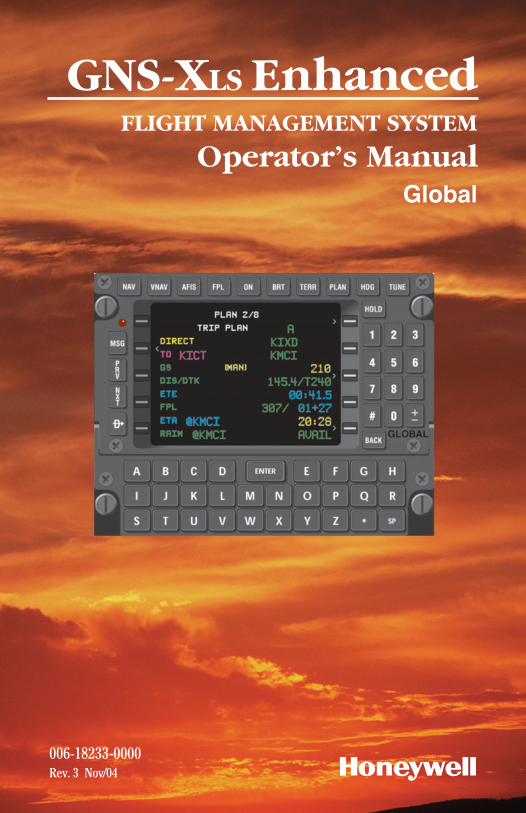
006-18233-0000Rev. 3 Nov/04
GNS-XLS EnhancedFLIGHT MANAGEMENT SYSTEM
Operator’s ManualGlobal
N

WARNING
Prior to export of this document, review for export license requirement isneeded.
COPYRIGHT NOTICE
Copyright ©2000-2002, 2004 Honeywell International Inc. All rightsreserved.
Reproduction of this publication or any portion thereof by any means withoutthe express written permission of Honeywell International Inc. is prohibited.For further information contact the Manager, Technical Publications;Honeywell; One Technology Center; 23500 West 105th Street; Olathe,Kansas 66061. Telephone: (913) 712-0400.
Revision History and Instructions
Manual GNS-XLS Enhanced FMS Operator’s Manual
Revision 3, November 2004
Part Number 006-18233-0000
This revision adds descriptions of operational procedures required to fly twokinds of SIDs.
Insert the contents of this revision packet according to the followinginstructions:
Front Cover Page Remove and Replace
Revision History Pages Remove and Replace
Section 3 Remove and Replace Pages 3-15 through 3-20
Back Cover Page Remove and Replace
Back Binder Insert Remove and Replace
Revision History
GNS-XLS Enhanced Flight Management System R-1Nov/04
Revision History
GNS-XLS Enhanced Flight Management SystemR-2 Nov/04
Revision History and Instructions
Manual GNS-XLS Enhanced FMS Operator’s Manual
Revision 2, September 2002
Part Number 006-18233-0000
This revision incorporates GNS-XLS Enhanced Software Mod 3 WxGraphics, change of the Regional Airline AFIS and miscellaneous correc-tions.
Insert the contents of this revision packet according to the followinginstructions:
Front Cover Page Remove and Replace
Revision History Pages Remove and Replace
Table of Contents Remove and Replace Page v and vi, Pages xi through xx
Section 2 Remove and Replace Pages 2-47 through 2-48
Section 3 Remove and Replace Pages 3-9 through 3-12, Add Pages 3-12a through 3-12b, Remove and Replace 3-77 through 3-78
Index Remove and Replace Pages I-1, I-2, I-7, I-8, I-11, I-12, I-13 and I-14
Back Cover Page Remove and Replace
Back Binder Insert Remove and Replace
Revision History and Instructions
Manual GNS-XLS Enhanced FMS Operator’s Manual
Revision 1, May 2001
Part Number 006-18233-0000
This revision incorporates GNS-XLS Enhanced Software Mod 3 WxGraphics, change of the Regional Airline AFIS and miscellaneous correc-tions.
Insert the contents of this revision packet according to the followinginstructions:
Front Cover Page Remove and Replace
Revision History Page Insert Ahead of Existing Revision History Page
Table of Contents Replace Pages xviii- xx with xvii and xviii.
Section 3 Remove and Replace Pages 3-13 through 3-20, 3-133 through 3-136, 3-141 through 3-146
Section 7 Remove and Replace entire section
Section 8 Remove and Replace entire section
Index Remove and Replace entire section
Back Cover Page Remove and Replace
Back Binder Insert Remove and Replace
Revision History
GNS-XLS Enhanced Flight Management System R-3Nov/04
Revision History
GNS-XLS Enhanced Flight Management SystemR-4 Nov/04
Revision History and Instructions
Manual GNS-XLS Enhanced FMS Operator’s Manual
Revision 0, June 2000
Part Number 006-18233-0000
This is the original version of this publication.
SECTION 1
DESCRIPTION . . . . . . . . . . . . . . . . . . . . . . . . . . . . . . . . . . . . . . . . . . . . . . . . . . .1-1
OVERVIEW . . . . . . . . . . . . . . . . . . . . . . . . . . . . . . . . . . . . . . . . . . . . . . . . . . .1-1
GENERAL TERMS . . . . . . . . . . . . . . . . . . . . . . . . . . . . . . . . . . . . . . . . . . . . . .1-3
CONTROLS AND INDICATORS . . . . . . . . . . . . . . . . . . . . . . . . . . . . . . . . . . . .1-4
ON: . . . . . . . . . . . . . . . . . . . . . . . . . . . . . . . . . . . . . . . . . . . . . . . . . . . . .1-4
BRIGHTNESS (BRT): . . . . . . . . . . . . . . . . . . . . . . . . . . . . . . . . . . . . . . . . .1-4
MESSAGE KEY/ANNUNCIATOR (MSG): . . . . . . . . . . . . . . . . . . . . . . . . . . .1-4
ALPHA KEYS: . . . . . . . . . . . . . . . . . . . . . . . . . . . . . . . . . . . . . . . . . . . . . . .1-5
NUMERIC KEYS: . . . . . . . . . . . . . . . . . . . . . . . . . . . . . . . . . . . . . . . . . . . .1-5
HOLD KEY: . . . . . . . . . . . . . . . . . . . . . . . . . . . . . . . . . . . . . . . . . . . . . . . . .1-5
BACK KEY: . . . . . . . . . . . . . . . . . . . . . . . . . . . . . . . . . . . . . . . . . . . . . . . . .1-6
ENTER Key: . . . . . . . . . . . . . . . . . . . . . . . . . . . . . . . . . . . . . . . . . . . . . . . .1-6
DISPLAY SELECTOR KEYS: . . . . . . . . . . . . . . . . . . . . . . . . . . . . . . . . . . . .1-6
AFIS KEY: . . . . . . . . . . . . . . . . . . . . . . . . . . . . . . . . . . . . . . . . . . . . . . . . . .1-7
TERRAIN (TERR) KEY: . . . . . . . . . . . . . . . . . . . . . . . . . . . . . . . . . . . . . . . .1-7
NEXT (NXT) KEY: . . . . . . . . . . . . . . . . . . . . . . . . . . . . . . . . . . . . . . . . . . . .1-7
LINE SELECT KEYS: . . . . . . . . . . . . . . . . . . . . . . . . . . . . . . . . . . . . . . . . . .1-8
COLORS: . . . . . . . . . . . . . . . . . . . . . . . . . . . . . . . . . . . . . . . . . . . . . . . . . .1-8
SECTION 2
PAGE DISPLAY DEFINITIONS . . . . . . . . . . . . . . . . . . . . . . . . . . . . . . . . . . . . . . .2-1
PAGE DISPLAYS AT POWER-UP . . . . . . . . . . . . . . . . . . . . . . . . . . . . . . . . . .2-1
SELF TEST PAGE . . . . . . . . . . . . . . . . . . . . . . . . . . . . . . . . . . . . . . . . . . . .2-1
INITIALIZATION PAGE . . . . . . . . . . . . . . . . . . . . . . . . . . . . . . . . . . . . . . . .2-1
FLIGHT PLAN SECTION (FPL KEY) . . . . . . . . . . . . . . . . . . . . . . . . . . . . . . . . .2-2
FLIGHT PLAN PAGES . . . . . . . . . . . . . . . . . . . . . . . . . . . . . . . . . . . . . . . . .2-2
FLIGHT PLAN LIST 1/1 (Page 1 of 1) . . . . . . . . . . . . . . . . . . . . . . . . . .2-2
Table of Contents
GNS-XLS Enhanced Flight Management System iRev. 0Jun/00
FLIGHT PLAN “X” 1/1 (Page 1 of 1) . . . . . . . . . . . . . . . . . . . . . . . . . . .2-3
DEPARTURE Page . . . . . . . . . . . . . . . . . . . . . . . . . . . . . . . . . . . . . . . . .2-5
ARRIVAL Page . . . . . . . . . . . . . . . . . . . . . . . . . . . . . . . . . . . . . . . . . . . .2-6
APPROACH Page . . . . . . . . . . . . . . . . . . . . . . . . . . . . . . . . . . . . . . . . . .2-7
AIRWAY Page . . . . . . . . . . . . . . . . . . . . . . . . . . . . . . . . . . . . . . . . . . . .2-9
ACTIVE FPOL (Flght Plan) Page . . . . . . . . . . . . . . . . . . . . . . . . . . . . . .2-10
NAVIGATION SECTION (NAV KEY) . . . . . . . . . . . . . . . . . . . . . . . . . . . . . . . .2-13
NAVIGATION PAGES . . . . . . . . . . . . . . . . . . . . . . . . . . . . . . . . . . . . . . . .2-13
NAVIGATION 1/4 (Page 1 of 4) . . . . . . . . . . . . . . . . . . . . . . . . . . . . . .2-13
NAVIGATION 2/4 (Page 2 of 4) . . . . . . . . . . . . . . . . . . . . . . . . . . . . . .2-17
NAVIGATION 3/4 (Page 3 of 4) . . . . . . . . . . . . . . . . . . . . . . . . . . . . . .2-19
NAVIGATION 4/4 (Page 4 of 4) . . . . . . . . . . . . . . . . . . . . . . . . . . . . . .2-20
IRS/INS SUBSECTION PAGES . . . . . . . . . . . . . . . . . . . . . . . . . . . . . . . . .2-21
IRS (or INS) SUBSECTION 1/2 (Page 1 of 2) . . . . . . . . . . . . . . . . . . .2-21
IRS SUBSECTION 2/2 (Page 2 of 2) . . . . . . . . . . . . . . . . . . . . . . . . . .2-21
VPU SUBSECTION PAGES . . . . . . . . . . . . . . . . . . . . . . . . . . . . . . . . . . . .2-22
VPU SUBSECTION 1/4 (Page 1 of 4) . . . . . . . . . . . . . . . . . . . . . . . . . .2-22
VPU SUBSECTION 2/4 (Page 2 of 4) . . . . . . . . . . . . . . . . . . . . . . . . . .2-22
VPU SUBSECTION 3/4 (Page 3 of 4) . . . . . . . . . . . . . . . . . . . . . . . . . .2-23
VPU SUBSECTION 4/4 (Page 4 of 4) . . . . . . . . . . . . . . . . . . . . . . . . . .2-24
GPS SUBSECTION PAGES . . . . . . . . . . . . . . . . . . . . . . . . . . . . . . . . . . . .2-25
GPS SUBSECTION 1/3 (Page 1 of 3) . . . . . . . . . . . . . . . . . . . . . . . . . .2-25
GPS SUBSECTION 2/3 (Page 2 of 3) . . . . . . . . . . . . . . . . . . . . . . . . . .2-25
GPS SUBSECTION 3/3 (Page 3 of 3) . . . . . . . . . . . . . . . . . . . . . . . . . .2-27
EXTERNAL GPS SENSOR SUBSECTION PAGES . . . . . . . . . . . . . . . . . . .2-28
GPS1 SUBSECTION 1/2 (Page 1 of 2) . . . . . . . . . . . . . . . . . . . . . . . . .2-28
GPS SUBSECTION 2/2 (Page 2 of 2) . . . . . . . . . . . . . . . . . . . . . . . . . .2-28
Table of Contents
GNS-XLS Enhanced Flight Management Systemii Rev. 0Jun/00
VERTICAL NAVIGATION SECTION (VNAV KEY) . . . . . . . . . . . . . . . . . . . . . .2-30
VNAV 1/3 (Page 1 of 3) . . . . . . . . . . . . . . . . . . . . . . . . . . . . . . . . . . . .2-30
VNAV 2/3 (Page 2 of 3) - FLIGHT PLAN WayPoint . . . . . . . . . . . . . . .2-35
VNAV DATA 1/1 (Page 1 of 1) . . . . . . . . . . . . . . . . . . . . . . . . . . . . . . .2-36
VNAV WAYPOINT 1/1 (Page 1 of 1) . . . . . . . . . . . . . . . . . . . . . . . . . .2-38
AFIS SECTION (AFIS KEY) . . . . . . . . . . . . . . . . . . . . . . . . . . . . . . . . . . . . . .2-40
PLANNING SECTION (PLAN KEY) . . . . . . . . . . . . . . . . . . . . . . . . . . . . . . . .2-40
PLAN PAGES . . . . . . . . . . . . . . . . . . . . . . . . . . . . . . . . . . . . . . . . . . . . . .2-40
PLAN 1/8 (Page 1 of 8) FUEL STATUS . . . . . . . . . . . . . . . . . . . . . . . .2-40
PLAN 2/8 (Page 2 of 8) TRIP PLAN . . . . . . . . . . . . . . . . . . . . . . . . . . .2-42
PLAN 3/8 (Page 3 of 8) FUEL PLAN . . . . . . . . . . . . . . . . . . . . . . . . . .2-44
PLAN 4/8 (Page 4 of 8) FUEL FLOW . . . . . . . . . . . . . . . . . . . . . . . . . .2-45
PLAN 5/8 (Page 5 of 8) DATE/GMT . . . . . . . . . . . . . . . . . . . . . . . . . . .2-45
PLAN 6/8 (Page 6 of 8) AIRCRAFT WEIGHT . . . . . . . . . . . . . . . . . . . .2-46
PLAN 7/8 (Page 7 of 8) FDE Prediction . . . . . . . . . . . . . . . . . . . . . . . .2-47
FDE EXCLUDE SATS 1/1 (Page 1 of 1) . . . . . . . . . . . . . . . . . . . . . . . .2-49
PLAN 8/8 (Page 8 of 8) FDE COMPUTATION . . . . . . . . . . . . . . . . . . . .2-49
HEADING SECTION (HDG KEY) . . . . . . . . . . . . . . . . . . . . . . . . . . . . . . . . . .2-51
HEADING PAGE . . . . . . . . . . . . . . . . . . . . . . . . . . . . . . . . . . . . . . . . . . . .2-51
HEADING VECTOR 1/1 (Page 1 of 1) . . . . . . . . . . . . . . . . . . . . . . . . . .2-51
TUNING SECTION (TUNE KEY) . . . . . . . . . . . . . . . . . . . . . . . . . . . . . . . . . . .2-53
TUNE 1/4 (Page 1 of 4) COMM . . . . . . . . . . . . . . . . . . . . . . . . . . . . . .2-53
TUNE 2/4 (Page 2 of 4) COMM . . . . . . . . . . . . . . . . . . . . . . . . . . . . . .2-53
TUNE 3/4 (Page 3 of 4) NAV . . . . . . . . . . . . . . . . . . . . . . . . . . . . . . . .2-54
TUNE 4/4 (Page 4 of 4) XPDR/ADF . . . . . . . . . . . . . . . . . . . . . . . . . . .2-55
HOLDING PATTERN SECTION (HOLD KEY) . . . . . . . . . . . . . . . . . . . . . . . . .2-56
HOLDING PATTERN PAGE . . . . . . . . . . . . . . . . . . . . . . . . . . . . . . . . . . . .2-56
Table of Contents
GNS-XLS Enhanced Flight Management System iiiRev. 0Jun/00
HOLDING PATTERN 1/1 (Page 1 of 1) . . . . . . . . . . . . . . . . . . . . . . . . .2-56
POSITION FIX PAGE . . . . . . . . . . . . . . . . . . . . . . . . . . . . . . . . . . . . . . . .2-61
DIRECT TO SECTION ( d KEY) . . . . . . . . . . . . . . . . . . . . . . . . . . . . . . . . . .2-62
DIRECT TO PAGES . . . . . . . . . . . . . . . . . . . . . . . . . . . . . . . . . . . . . . . . . .2-62
DIRECT 1/2 (Page 1 of 2) . . . . . . . . . . . . . . . . . . . . . . . . . . . . . . . . . .2-62
DIRECT CLOSEST ARP 2/2 (Page 2 of 2) . . . . . . . . . . . . . . . . . . . . . .2-63
WAYPOINT SECTION . . . . . . . . . . . . . . . . . . . . . . . . . . . . . . . . . . . . . . . . . .2-63
WAYPOINT PAGES . . . . . . . . . . . . . . . . . . . . . . . . . . . . . . . . . . . . . . . . .2-63
DATABASE WPT 1/1 (Page 1 of 1) . . . . . . . . . . . . . . . . . . . . . . . . . . .2-63
SPECIAL DATABASE WAYPOINTS . . . . . . . . . . . . . . . . . . . . . . . . . . . . . .2-67
PILOT ENTERED WPT (Personalized) Waypoint . . . . . . . . . . . . . . . . .2-67
OFFSET WAYPOINT . . . . . . . . . . . . . . . . . . . . . . . . . . . . . . . . . . . . . . .2-68
SPECIAL WAYPOINTS . . . . . . . . . . . . . . . . . . . . . . . . . . . . . . . . . . . . .2-69
POWER OFF WAYPOINT . . . . . . . . . . . . . . . . . . . . . . . . . . . . . . . . . . .2-70
OCEANIC REPORTING WAYPOINTS . . . . . . . . . . . . . . . . . . . . . . . . . . . .2-70
OBSOLETE WAYPOINT . . . . . . . . . . . . . . . . . . . . . . . . . . . . . . . . . . . . . .2-71
MESSAGES (MSG Key) . . . . . . . . . . . . . . . . . . . . . . . . . . . . . . . . . . . . . . . .2-71
SYSTEM MESSAGES . . . . . . . . . . . . . . . . . . . . . . . . . . . . . . . . . . . . . . . .2-72
ACTION REQUIRED: . . . . . . . . . . . . . . . . . . . . . . . . . . . . . . . . . . . . . .2-72
ADVISORY: . . . . . . . . . . . . . . . . . . . . . . . . . . . . . . . . . . . . . . . . . . . . .2-72
SENSOR MESSAGES . . . . . . . . . . . . . . . . . . . . . . . . . . . . . . . . . . . . . . . .2-76
SECTION 3
SYSTEM OPERATION . . . . . . . . . . . . . . . . . . . . . . . . . . . . . . . . . . . . . . . . . . . . .3-1
PRE-DEPARTURE . . . . . . . . . . . . . . . . . . . . . . . . . . . . . . . . . . . . . . . . . . . . . .3-1
POWER ON/OFF AND PARALLAX ADJUSTMENT . . . . . . . . . . . . . . . . . . . .3-1
INITIALIZATION PAGE . . . . . . . . . . . . . . . . . . . . . . . . . . . . . . . . . . . . . . . .3-2
DATE and GMT . . . . . . . . . . . . . . . . . . . . . . . . . . . . . . . . . . . . . . . . . . . . .3-2
Table of Contents
GNS-XLS Enhanced Flight Management Systemiv Rev. 0Jun/00
INITIALIZATION POSITION . . . . . . . . . . . . . . . . . . . . . . . . . . . . . . . . . . . .3-3
Option 1: Using the IDENT field for non-IRS equipped systems . . . . . .3-3
Option 2: Using the POS field . . . . . . . . . . . . . . . . . . . . . . . . . . . . . . . .3-5
BUILDING FLIGHT PLANS (FPL) . . . . . . . . . . . . . . . . . . . . . . . . . . . . . . . . . .3-7
CREATING A FLIGHT PLAN . . . . . . . . . . . . . . . . . . . . . . . . . . . . . . . . . . . .3-7
To Delete a Waypoint . . . . . . . . . . . . . . . . . . . . . . . . . . . . . . . . . . . . . .3-8
MODIFYING A FLIGHT PLAN . . . . . . . . . . . . . . . . . . . . . . . . . . . . . . . . . . .3-8
To Access The Desired Flight Plan: . . . . . . . . . . . . . . . . . . . . . . . . . . . .3-8
Deleting A Waypoint: . . . . . . . . . . . . . . . . . . . . . . . . . . . . . . . . . . . . . . .3-9
ADDING A WAYPOINT . . . . . . . . . . . . . . . . . . . . . . . . . . . . . . . . . . . . . . . .3-9
Adding Oceanic Waypoints . . . . . . . . . . . . . . . . . . . . . . . . . . . . . . . . .3-10
ERASING A STORED FLIGHT PLAN . . . . . . . . . . . . . . . . . . . . . . . . . . . . .3-11
USING DUPLICATE WAYPOINT IDENTIFIERS . . . . . . . . . . . . . . . . . . . . .3-12
REVIEWING WAYPOINT DATA/COORDINATES (FLIGHT PLAN PAGES ONLY) . . . . . . . . . . . . . . . . . . . . . . . . . . . . . . . . .3-12
FLIGHT PLAN (FPL) SELECTION . . . . . . . . . . . . . . . . . . . . . . . . . . . . . . . . .3-13
INITIAL LEG SELECTION . . . . . . . . . . . . . . . . . . . . . . . . . . . . . . . . . . . . .3-14
BEFORE TAXI (IRS EQUIPPED) . . . . . . . . . . . . . . . . . . . . . . . . . . . . . . . .3-15
RUNWAY LINE-UP (IRS EQUIPPED) . . . . . . . . . . . . . . . . . . . . . . . . . . . . . .3-15
IRS, GPS AND/OR VPU EQUIPPED . . . . . . . . . . . . . . . . . . . . . . . . . . . . .3-15
VPU EQUIPPED ONLY . . . . . . . . . . . . . . . . . . . . . . . . . . . . . . . . . . . . . . .3-15
SIDs, STARs, APPROACHES AND ENROUTE AIRWAYS . . . . . . . . . . . . .3-16
ENTERING A SID ON THE ACTIVE FPL . . . . . . . . . . . . . . . . . . . . . . . . . .3-18
REVIEWING A SID FROM ANY STORED FPL OR THE ACTIVE FPL PAGE 3-20
EDITING A SID FROM ANY STORED FPL OR THE ACTIVE FPL PAGE . . .3-21
ERASING A SID FROM ANY STORED FPL OR THE ACTIVE FPL PAGE . .3-22
ADDING OR DELETING WAYPOINTS WITHIN A SID . . . . . . . . . . . . . . . .3-23
To Add a Waypoint . . . . . . . . . . . . . . . . . . . . . . . . . . . . . . . . . . . . . . .3-23
Table of Contents
GNS-XLS Enhanced Flight Management System vRev. 2Sep/02
To Delete a Waypoint . . . . . . . . . . . . . . . . . . . . . . . . . . . . . . . . . . . . . .3-23
ENTERING AN AIRWAY FROM ANY STORED FPL OR THE ACTIVE FPL PAGE . . . . . . . . . . . . . . . . . . . . . . . . . . . . . . . . . . .3-24
Option 1 . . . . . . . . . . . . . . . . . . . . . . . . . . . . . . . . . . . . . . . . . . . . . . . .3-24
Option 2 . . . . . . . . . . . . . . . . . . . . . . . . . . . . . . . . . . . . . . . . . . . . . . .3-25
EDITING AN AIRWAY . . . . . . . . . . . . . . . . . . . . . . . . . . . . . . . . . . . . . . . .3-26
ENTERING A STAR OR PROFILE DESCENT ON ANY STORED FPL OR THE ACTIVE FPL PAGE . . . . . . . . . . . . . . . . . . . . . . . . . . . . . . . . . . .3-27
REVIEWING A STAR FROM A STORED FPL OR THE ACTIVE FPL PAGE .3-29
EDITING A STAR FROM A STORED FPL OR THE ACTIVE FPL PAGE . . . .3-29
ERASING A STAR FROM A STORED FPL OR THE ACTIVE FPL PAGE . . .3-30
ADDING WAYPOINTS WITHIN A STAR . . . . . . . . . . . . . . . . . . . . . . . . . .3-31
DELETING WAYPOINTS OF A STAR . . . . . . . . . . . . . . . . . . . . . . . . . . . .3-31
ENTERING AN APPROACH ON A STORED FPL OR THE ACTIVE FPL PAGE . . . . . . . . . . . . . . . . . . . . . . . . . . . . . . . . . . .3-32
REVIEWING AN APPROACH FROM A STORED FPL OR THE ACTIVE FPL PAGE . . . . . . . . . . . . . . . . . . . . . . . . . . . . . . . . . . .3-34
EDITING AN APPROACH FROM A STORED FPLOR THE ACTIVE FPL PAGE . . . . . . . . . . . . . . . . . . . . . . . . . . . . . . . . . . .3-34
ERASING AN APPROACH FROM A STORED FPL OR THE ACTIVE FPL . . . . . . . . . . . . . . . . . . . . . . . . . . . . . . . . . . . . . . . .3-35
DELETING AN APPROACH WAYPOINT . . . . . . . . . . . . . . . . . . . . . . . . . .3-36
USING A STAR AND AN APPROACH IN THE SAME FLIGHT PLAN . . . . .3-36
SELECTING A COMPANY ROUTE AND ADDING ITTO THE ACTIVE FLIGHT PLAN . . . . . . . . . . . . . . . . . . . . . . . . . . . . . . . . .3-37
EXECUTING APPROACHES . . . . . . . . . . . . . . . . . . . . . . . . . . . . . . . . . . . . .3-39
LOADING A GPS/GPS OVERLAY APPROACH . . . . . . . . . . . . . . . . . . . . .3-40
EXECUTING A GPS/GPS OVERLAY APPROACH . . . . . . . . . . . . . . . . . . .3-41
Using Radar Vectors to FINAL APPROACH COURSE . . . . . . . . . . . . . .3-41
USING OWN NAVIGATION - NO DME ARC . . . . . . . . . . . . . . . . . . . . .3-42
Table of Contents
GNS-XLS Enhanced Flight Management Systemvi Rev. 0Jun/00
PROCEDURE TURN . . . . . . . . . . . . . . . . . . . . . . . . . . . . . . . . . . . . . . . . .3-43
USING RADAR VECTORS TO INTERCEPT A DME ARC . . . . . . . . . . . . . .3-46
USING OWN NAVIGATION TO FLY DME ARC . . . . . . . . . . . . . . . . . . .3-48
ENROUTE . . . . . . . . . . . . . . . . . . . . . . . . . . . . . . . . . . . . . . . . . . . . . . . . . . .3-53
DIRECT TO - ACTIVE FLIGHT PLAN WAYPOINT . . . . . . . . . . . . . . . . . . .3-53
DIRECT TO - HP WAYPOINT . . . . . . . . . . . . . . . . . . . . . . . . . . . . . . . . . .3-54
To Select and Go Direct To HP Waypoint: . . . . . . . . . . . . . . . . . . . . . .3-54
To Cancel Holding Pattern:(from the Holding Pattern page) . . . . . . . .3-54
DIRECT TO - RANDOM WAYPOINT . . . . . . . . . . . . . . . . . . . . . . . . . . . . .3-55
DIRECT TO - CLOSEST AIRPORT . . . . . . . . . . . . . . . . . . . . . . . . . . . . . .3-56
PSEUDO-VORTAC (SELECTED COURSE) . . . . . . . . . . . . . . . . . . . . . . . .3-57
USING HEADING VECTOR . . . . . . . . . . . . . . . . . . . . . . . . . . . . . . . . . . . . . .3-59
PROGRAMMING A HEADING VECTOR . . . . . . . . . . . . . . . . . . . . . . . . . .3-59
CHANGING HEADING VECTOR WHILE IN HEADING SELECT MODE . . . .3-60
CHANGING TO WAYPOINT WHILE IN HEADING SELECT MODE . . . . . . .3-60
CANCELING HEADING SELECT MODE . . . . . . . . . . . . . . . . . . . . . . . . . . .3-61
PROGRAMMING AN INTERCEPT . . . . . . . . . . . . . . . . . . . . . . . . . . . . . . .3-61
PROGRAMMING A HEADING INTERCEPT TO THE FINAL APPROACH COURSE . . . . . . . . . . . . . . . . . . . . . . . . . . . . . . . . . .3-63
PROGRAMMING A HOLDING PATTERN . . . . . . . . . . . . . . . . . . . . . . . . . . . .3-65
REVIEWING, EDITING, OR CANCELING A HOLDING PATTERN . . . . . . . . . .3-67
REVIEWING . . . . . . . . . . . . . . . . . . . . . . . . . . . . . . . . . . . . . . . . . . . . . . .3-67
EDITING . . . . . . . . . . . . . . . . . . . . . . . . . . . . . . . . . . . . . . . . . . . . . . . . . .3-68
CANCELING . . . . . . . . . . . . . . . . . . . . . . . . . . . . . . . . . . . . . . . . . . . . . . .3-68
EXITING A HOLDING PATTERN . . . . . . . . . . . . . . . . . . . . . . . . . . . . . . . . . .3-68
EXITING HOLDING PATTERN NEXT TIME OVER HOLDING FIX . . . . . . . .3-69
EXITING HOLDING PATTERN BY GOING DIRECT TO HOLDING FIX . . . .3-70
EXITING HOLDING PATTERN BY PERFORMING A LEG CHANGE . . . . . .3-70
Table of Contents
GNS-XLS Enhanced Flight Management System viiRev. 0Jun/00
VERTICAL NAVIGATION (VNAV) OPERATION - PRE-DEPARTURE . . . . . . .3-73
SETTING CRUISE ALTITUDE, TRANSITION LEVEL, AND DEFAULT FLIGHT PATH ANGLE . . . . . . . . . . . . . . . . . . . . . . . . . . . .3-73
CREATING/CHANGING VNAV WAYPOINTS . . . . . . . . . . . . . . . . . . . . . . .3-74
To program a Path Descent . . . . . . . . . . . . . . . . . . . . . . . . . . . . . . . .3-76
REVIEWING VNAV WAYPOINTS . . . . . . . . . . . . . . . . . . . . . . . . . . . . . . .3-77
Using Active Flight Plan Page . . . . . . . . . . . . . . . . . . . . . . . . . . . . . . .3-77
Using VNAV Flight Plan Waypoints Page . . . . . . . . . . . . . . . . . . . . . . .3-78
VERTICAL NAVIGATION - ENROUTE . . . . . . . . . . . . . . . . . . . . . . . . . . . . . .3-78
PROGRAMMING VERTICAL PATH DESCENTS . . . . . . . . . . . . . . . . . . . .3-78
Using Database (DB) FPA . . . . . . . . . . . . . . . . . . . . . . . . . . . . . . . . . .3-79
Using Default (DEF) FPA . . . . . . . . . . . . . . . . . . . . . . . . . . . . . . . . . . .3-79
Using Manual (MAN) FPA . . . . . . . . . . . . . . . . . . . . . . . . . . . . . . . . . .3-79
Using Automatic (AUTO) FPA . . . . . . . . . . . . . . . . . . . . . . . . . . . . . . .3-80
EDITING ALTITUDE CONSTRAINTS . . . . . . . . . . . . . . . . . . . . . . . . . . . . .3-81
Option 1: Using VNAV Page . . . . . . . . . . . . . . . . . . . . . . . . . . . . . . . . .3-81
Option 2: Using VNAV FPL WAYPOINT Page . . . . . . . . . . . . . . . . . . . .3-81
Option 3: Using the VNAV WAYPOINT Page . . . . . . . . . . . . . . . . . . . .3-82
DIRECT TO - VNAV WAYPOINT AS LATERAL WAYPOINT . . . . . . . . . . . .3-83
DIRECT TO - VNAV WAYPOINT . . . . . . . . . . . . . . . . . . . . . . . . . . . . . . . .3-85
CREATING VNAV PROFILE WAYPOINTS . . . . . . . . . . . . . . . . . . . . . . . . .3-86
Top of Climb (#TOC) . . . . . . . . . . . . . . . . . . . . . . . . . . . . . . . . . . . . . .3-86
Top of Descent (#TOD) . . . . . . . . . . . . . . . . . . . . . . . . . . . . . . . . . . . .3-87
Pre-Selected Altitude Intercept Point (#PRESL) . . . . . . . . . . . . . . . . .3-88
Descent Reference Waypoints . . . . . . . . . . . . . . . . . . . . . . . . . . . . . . .3-88
REMOTE TUNING . . . . . . . . . . . . . . . . . . . . . . . . . . . . . . . . . . . . . . . . . . . . . . .3-91
TUNING COMMS . . . . . . . . . . . . . . . . . . . . . . . . . . . . . . . . . . . . . . . . . . . . .3-91
TUNING NAVs . . . . . . . . . . . . . . . . . . . . . . . . . . . . . . . . . . . . . . . . . . . . . . .3-92
Table of Contents
GNS-XLS Enhanced Flight Management Systemviii Rev. 0Jun/00
Keyboard Method . . . . . . . . . . . . . . . . . . . . . . . . . . . . . . . . . . . . . . . .3-92
Auto Tune Method . . . . . . . . . . . . . . . . . . . . . . . . . . . . . . . . . . . . . . .3-94
TRANSPONDER AND ADF KEYBOARD TUNE . . . . . . . . . . . . . . . . . . . . .3-95
PLANNING PROCEDURES . . . . . . . . . . . . . . . . . . . . . . . . . . . . . . . . . . . . . .3-97
FUEL PLANNING . . . . . . . . . . . . . . . . . . . . . . . . . . . . . . . . . . . . . . . . . . .3-97
TRIP PLANNING . . . . . . . . . . . . . . . . . . . . . . . . . . . . . . . . . . . . . . . . . . .3-98
To Enter Manual Groundspeed: . . . . . . . . . . . . . . . . . . . . . . . . . . . . .3-100
To Return to Automatic Groundspeed: . . . . . . . . . . . . . . . . . . . . . . .3-100
To update the TRIP PLAN leg to the current TO waypoint with an Active Flight Plan selected: . . . . . . . . . . . . . . . . . . . . . . . . . .3-102
FLIGHT PLAN FUEL PLANNING . . . . . . . . . . . . . . . . . . . . . . . . . . . . . . .3-102
To Enter Manual Groundspeed: . . . . . . . . . . . . . . . . . . . . . . . . . . . . .3-104
To Return To Automatic Groundspeed: . . . . . . . . . . . . . . . . . . . . . . .3-104
To Enter A Manual Fuel Flow: . . . . . . . . . . . . . . . . . . . . . . . . . . . . . .3-104
To Return to Automatic Fuel Flow: . . . . . . . . . . . . . . . . . . . . . . . . . .3-104
VERIFYING OR CHANGING DATE AND TIME . . . . . . . . . . . . . . . . . . . . .3-106
VERIFYING OR CHANGING AIRCRAFT WEIGHT PARAMETERS . . . . . .3-107
RESETTING FUEL USED . . . . . . . . . . . . . . . . . . . . . . . . . . . . . . . . . . . .3-108
SPECIAL PROCEDURES . . . . . . . . . . . . . . . . . . . . . . . . . . . . . . . . . . . . . . .3-109
PILOT ENTERED LEG CHANGE . . . . . . . . . . . . . . . . . . . . . . . . . . . . . . .3-109
PREVENTING AUTOMATIC LEG CHANGES . . . . . . . . . . . . . . . . . . . . . .3-111
POSITION CHECK AND UPDATE PROCEDURES . . . . . . . . . . . . . . . . . .3-112
Using a Sensor . . . . . . . . . . . . . . . . . . . . . . . . . . . . . . . . . . . . . . . . .3-112
Over Known Point . . . . . . . . . . . . . . . . . . . . . . . . . . . . . . . . . . . . . . .3-113
Using An Offset . . . . . . . . . . . . . . . . . . . . . . . . . . . . . . . . . . . . . . . . .3-115
PARALLEL COURSE . . . . . . . . . . . . . . . . . . . . . . . . . . . . . . . . . . . . . . .3-116
MANUAL MAGNETIC VARIATION ENTRY . . . . . . . . . . . . . . . . . . . . . . .3-117
RETURNING TO AUTOMATIC VARIATION . . . . . . . . . . . . . . . . . . . . . . .3-117
Table of Contents
GNS-XLS Enhanced Flight Management System ixRev. 0Jun/00
SELECTING ETE, ETA, DIS, OR ALT DISPLAY OPTION . . . . . . . . . . . . .3-117
SELECTING NAV PAGE ETA OR ALT DISPLAY OPTION . . . . . . . . . . . . .3-118
SENSOR DESELECTION . . . . . . . . . . . . . . . . . . . . . . . . . . . . . . . . . . . . .3-119
EXTERNAL WAYPOINT ACCEPTANCE . . . . . . . . . . . . . . . . . . . . . . . . . .3-120
PRESENT POSITION AS A WAYPOINT . . . . . . . . . . . . . . . . . . . . . . . . .3-121
NAVIGATION AT EWXTREME LATITUDES . . . . . . . . . . . . . . . . . . . . . . .3-122
TRUE HEADING . . . . . . . . . . . . . . . . . . . . . . . . . . . . . . . . . . . . . . . . . . .3-122
Aircraft Equipped With TRUE/MAG Switch . . . . . . . . . . . . . . . . . . . .3-122
Aircraft Not Equipped With A TRUE/MAG Switch . . . . . . . . . . . . . . .3-123
SET HEADING ENTRY . . . . . . . . . . . . . . . . . . . . . . . . . . . . . . . . . . . . . .3-123
LOSS OF POWER IN FLIGHT . . . . . . . . . . . . . . . . . . . . . . . . . . . . . . . . .3-124
CREATING/CHANGING PILOT ENTERED (PERSONALIZED) WAYPOINTS 3-125
Creating Pilot Entered (Personalized) Waypoints: . . . . . . . . . . . . . . .3-126
Changing Pilot Entered (Personalized) Waypoints: . . . . . . . . . . . . . .3-126
CREATING AN OFFSET WAYPOINT . . . . . . . . . . . . . . . . . . . . . . . . . . . .3-127
PERFORMING FDE PREDICTION FOR OCEANIC/REMOTE OPERATION . . .3-128
SEARCH AND RESCUE . . . . . . . . . . . . . . . . . . . . . . . . . . . . . . . . . . . . . . . .3-133
Introduction . . . . . . . . . . . . . . . . . . . . . . . . . . . . . . . . . . . . . . . . . . . . . .3-133
Search Patterns . . . . . . . . . . . . . . . . . . . . . . . . . . . . . . . . . . . . . . . . .3-133
Break and Resume . . . . . . . . . . . . . . . . . . . . . . . . . . . . . . . . . . . . . .3-133
Enhanced Steering . . . . . . . . . . . . . . . . . . . . . . . . . . . . . . . . . . . . . . .3-133
Target Waypoints . . . . . . . . . . . . . . . . . . . . . . . . . . . . . . . . . . . . . . .3-133
WGS-84 to Tokyo Datum Calculation . . . . . . . . . . . . . . . . . . . . . . . .3-133
Accessing the Search Pattern Planning Pages . . . . . . . . . . . . . . . . . . . .3-134
Search pattern waypoint naming . . . . . . . . . . . . . . . . . . . . . . . . . . . . . .3-134
Ladder Search Pattern . . . . . . . . . . . . . . . . . . . . . . . . . . . . . . . . . . . . . .3-135
Parallel Line Search Pattern . . . . . . . . . . . . . . . . . . . . . . . . . . . . . . . . . .3-136
Table of Contents
GNS-XLS Enhanced Flight Management Systemx Rev. 0Jun/00
Sector Search Pattern . . . . . . . . . . . . . . . . . . . . . . . . . . . . . . . . . . . . . .3-139
Expanding Square Search Pattern . . . . . . . . . . . . . . . . . . . . . . . . . . . . .3-141
Orbit Search Pattern . . . . . . . . . . . . . . . . . . . . . . . . . . . . . . . . . . . . . . .3-142
Search Pattern Break and Resume . . . . . . . . . . . . . . . . . . . . . . . . . . . . .3-144
Target Waypoints . . . . . . . . . . . . . . . . . . . . . . . . . . . . . . . . . . . . . . . . . .3-145
WGS-84 to Tokyo Datum Calculation . . . . . . . . . . . . . . . . . . . . . . . . . . .3-146
SECTION 4
ENHANCED GROUND PROXIMITY WARNING SYSTEM (EGPWS) . . . . . . . . . . .4-1
GNS-XLS TERRAIN OPERATION . . . . . . . . . . . . . . . . . . . . . . . . . . . . . . . . . .4-1
Terrain PROFILE display . . . . . . . . . . . . . . . . . . . . . . . . . . . . . . . . . . . . . .4-1
TERRAIN Center Mode display . . . . . . . . . . . . . . . . . . . . . . . . . . . . . . . . . .4-2
SECTION 5
DATABASE UPDATE . . . . . . . . . . . . . . . . . . . . . . . . . . . . . . . . . . . . . . . . . . . . . .5-1
DATA BASE UPDATE PROCEDURES . . . . . . . . . . . . . . . . . . . . . . . . . . . . . . .5-1
TO UPDATE . . . . . . . . . . . . . . . . . . . . . . . . . . . . . . . . . . . . . . . . . . . . . . . .5-1
WHEN UPDATE IS COMPLETE . . . . . . . . . . . . . . . . . . . . . . . . . . . . . . . . . .5-2
IF UPDATE FAILS . . . . . . . . . . . . . . . . . . . . . . . . . . . . . . . . . . . . . . . . . . . .5-2
SECTION 6
LIST OF ABBREVIATIONS AND DEFINITIONS . . . . . . . . . . . . . . . . . . . . . . . . . . .6-1
SECTION 7
Description . . . . . . . . . . . . . . . . . . . . . . . . . . . . . . . . . . . . . . . . . . . . . . . . . . .7-1
Global Data Center (GDC) . . . . . . . . . . . . . . . . . . . . . . . . . . . . . . . . . . . . .7-2
Data Transfer Unit (DTU) . . . . . . . . . . . . . . . . . . . . . . . . . . . . . . . . . . . . . .7-2
Data Management Unit (DMU) . . . . . . . . . . . . . . . . . . . . . . . . . . . . . . . . . .7-2
Antenna Switching Unit (ASU) . . . . . . . . . . . . . . . . . . . . . . . . . . . . . . . . . .7-2
Satellite Communications Unit (SCU) . . . . . . . . . . . . . . . . . . . . . . . . . . . .7-3
High Power Amplifier/ Low Noise Amplifier (HPA/LNA) . . . . . . . . . . . . . . .7-3
Table of Contents
GNS-XLS Enhanced Flight Management System xiRev. 0Jun/00
Satellite Antenna . . . . . . . . . . . . . . . . . . . . . . . . . . . . . . . . . . . . . . . . . . . .7-3
REMOTE PROCESSING Unit (RPU) . . . . . . . . . . . . . . . . . . . . . . . . . . . . . .7-3
PAGE DISPLAY DEFINITIONS . . . . . . . . . . . . . . . . . . . . . . . . . . . . . . . . . . . .7-3
AFIS Flight Plan List Page . . . . . . . . . . . . . . . . . . . . . . . . . . . . . . . . . . . . .7-3
Flight Plan Progress (NAVIGATION Page 5) . . . . . . . . . . . . . . . . . . . . . . .7-4
AFIS Menu Page . . . . . . . . . . . . . . . . . . . . . . . . . . . . . . . . . . . . . . . . . . . .7-6
AFIS FLT PLAN Pages . . . . . . . . . . . . . . . . . . . . . . . . . . . . . . . . . . . . . . . .7-7
AFIS FLT PLAN Page 1 . . . . . . . . . . . . . . . . . . . . . . . . . . . . . . . . . . . . . . . .7-7
Fuel and Time Require-ments . . . . . . . . . . . . . . . . . . . . . . . . . . . . . . . .7-7
AFIS FLT PLAN Page 2 . . . . . . . . . . . . . . . . . . . . . . . . . . . . . . . . . . . . . . . .7-9
Weights, Flight Level and Route . . . . . . . . . . . . . . . . . . . . . . . . . . . . . .7-9
AFIS FLT PLAN Page 3 . . . . . . . . . . . . . . . . . . . . . . . . . . . . . . . . . . . . . . .7-10
Operator Inputs . . . . . . . . . . . . . . . . . . . . . . . . . . . . . . . . . . . . . . . . . .7-10
AFIS FLT PLAN Page 4 . . . . . . . . . . . . . . . . . . . . . . . . . . . . . . . . . . . . . . .7-11
Performance Bias . . . . . . . . . . . . . . . . . . . . . . . . . . . . . . . . . . . . . . . .7-11
SIGMETS Pages . . . . . . . . . . . . . . . . . . . . . . . . . . . . . . . . . . . . . . . . . . . .7-11
TERMINAL WEATHER Pages . . . . . . . . . . . . . . . . . . . . . . . . . . . . . . . . . .7-12
TERMINAL WX DATA Pages . . . . . . . . . . . . . . . . . . . . . . . . . . . . . . . . . .7-13
WINDS ALOFT Pages . . . . . . . . . . . . . . . . . . . . . . . . . . . . . . . . . . . . . . . .7-13
WINDS ALOFT Data Pages . . . . . . . . . . . . . . . . . . . . . . . . . . . . . . . . . . . .7-13
RECALL AFIS FPL Page . . . . . . . . . . . . . . . . . . . . . . . . . . . . . . . . . . . . . .7-14
SEND AFIS MESSAGE Page . . . . . . . . . . . . . . . . . . . . . . . . . . . . . . . . . . .7-15
PPM MENU Page (Preprogrammed Messages) . . . . . . . . . . . . . . . . . . . .7-17
PREPROGRAMMED MESSAGE Pages . . . . . . . . . . . . . . . . . . . . . . . . . . .7-17
DISPLAY AFIS MSG Page . . . . . . . . . . . . . . . . . . . . . . . . . . . . . . . . . . . .7-18
OPERATING MODES Page (For AFIS Users Equipped with Satellite Data Communications System) . . . . . . . . . . . . . . . . . . . . . . . . .7-18
AUTO REPORT: . . . . . . . . . . . . . . . . . . . . . . . . . . . . . . . . . . . . . . . . . .7-18
Table of Contents
GNS-XLS Enhanced Flight Management Systemxii Rev. 2Sep/02
AUTO WX UPDT (weather update): . . . . . . . . . . . . . . . . . . . . . . . . . . .7-19
VHF LINK CONTROL Page . . . . . . . . . . . . . . . . . . . . . . . . . . . . . . . . . . . .7-20
SAT LINK CONTROL Page . . . . . . . . . . . . . . . . . . . . . . . . . . . . . . . . . . . .7-20
OPERATING MODES Page (For AFIS Users NOT Equipped with Satellite Data Communications System) . . . . . . . . . . . . . . . . . . . . . . . . .7-21
AUTO REPORT: . . . . . . . . . . . . . . . . . . . . . . . . . . . . . . . . . . . . . . . . . .7-21
AUTO WX UPDT (weather update): . . . . . . . . . . . . . . . . . . . . . . . . . . .7-22
Active Flight Plan Page (for AFIS Flight Plan Updating) . . . . . . . . . . . . . .7-23
AFIS UPDATE Verification Page . . . . . . . . . . . . . . . . . . . . . . . . . . . . . . . .7-23
SYSTEM MESSAGES Page . . . . . . . . . . . . . . . . . . . . . . . . . . . . . . . . . . .7-24
SYSTEM MESSAGES . . . . . . . . . . . . . . . . . . . . . . . . . . . . . . . . . . . . . . . .7-24
ADVISORY: . . . . . . . . . . . . . . . . . . . . . . . . . . . . . . . . . . . . . . . . . . . . .7-24
SYSTEM OPERATION . . . . . . . . . . . . . . . . . . . . . . . . . . . . . . . . . . . . . . . . . .7-27
Pre-Departure . . . . . . . . . . . . . . . . . . . . . . . . . . . . . . . . . . . . . . . . . . . . . . . .7-27
AFIS Flight Plan Selection . . . . . . . . . . . . . . . . . . . . . . . . . . . . . . . . . . . .7-27
To enter an AFIS Flight Plan . . . . . . . . . . . . . . . . . . . . . . . . . . . . . . . . . . .7-27
ENROUTE . . . . . . . . . . . . . . . . . . . . . . . . . . . . . . . . . . . . . . . . . . . . . . . . . . .7-28
Reviewing Flight Plan Progress . . . . . . . . . . . . . . . . . . . . . . . . . . . . . . . .7-28
Reviewing AFIS Planned Leg Data . . . . . . . . . . . . . . . . . . . . . . . . . . . . . .7-28
Reviewing AFIS Flight Plan Data . . . . . . . . . . . . . . . . . . . . . . . . . . . . . . .7-29
AFIS Flight Plan Page 1 . . . . . . . . . . . . . . . . . . . . . . . . . . . . . . . . . . . . . .7-29
AFIS Flight Plan Page 2 . . . . . . . . . . . . . . . . . . . . . . . . . . . . . . . . . . . . . .7-30
AFIS Flight Plan Page 3 . . . . . . . . . . . . . . . . . . . . . . . . . . . . . . . . . . . . . .7-31
AFIS Flight Plan Page 4 . . . . . . . . . . . . . . . . . . . . . . . . . . . . . . . . . . . . . .7-31
SIGMETS Review/update . . . . . . . . . . . . . . . . . . . . . . . . . . . . . . . . . . . . .7-32
Terminal Weather Menu - Data update and Review . . . . . . . . . . . . . . . . .7-33
To insert a new identifier: . . . . . . . . . . . . . . . . . . . . . . . . . . . . . . . . . .7-34
To delete text when there is no data entry in progress: . . . . . . . . . . . .7-34
Table of Contents
GNS-XLS Enhanced Flight Management System xiiiRev. 2Sep/02
Winds Aloft Menu - Data update and Review . . . . . . . . . . . . . . . . . . . . . .7-34
To insert a new identifier: . . . . . . . . . . . . . . . . . . . . . . . . . . . . . . . . . .7-35
To delete text when there is no data entry in progress: . . . . . . . . . . .7-36
Recalling AFIS Flight Plan . . . . . . . . . . . . . . . . . . . . . . . . . . . . . . . . . . . .7-36
Recall Option 1: . . . . . . . . . . . . . . . . . . . . . . . . . . . . . . . . . . . . . . . . . .7-36
Recall Option 2: . . . . . . . . . . . . . . . . . . . . . . . . . . . . . . . . . . . . . . . . . .7-37
Sending a Text Message or pdc . . . . . . . . . . . . . . . . . . . . . . . . . . . . . . .7-38
To Return to the AFIS Menu Page . . . . . . . . . . . . . . . . . . . . . . . . . . . . . .7-40
Sending/building a Preprogrammed Message . . . . . . . . . . . . . . . . . . . . .7-41
Editing/entering a Preprogrammed Message . . . . . . . . . . . . . . . . . . . . . .7-42
Continue Sending Message . . . . . . . . . . . . . . . . . . . . . . . . . . . . . . . . . . .7-42
AFIS Messages Review . . . . . . . . . . . . . . . . . . . . . . . . . . . . . . . . . . . . . .7-43
Selecting Operating Modes (For AFIS Users Equipped withSatellite Data Communications System) . . . . . . . . . . . . . . . . . . . . . . . . .7-43
Auto Reporting . . . . . . . . . . . . . . . . . . . . . . . . . . . . . . . . . . . . . . . . . .7-43
Turning AUTO REPORT / auto wx update OFF . . . . . . . . . . . . . . . . . . .7-44
Returning to AUTO REPORT/auto wx update . . . . . . . . . . . . . . . . . . . .7-45
Auto Weather Update . . . . . . . . . . . . . . . . . . . . . . . . . . . . . . . . . . . . .7-46
Turning AUTO WX UPDT OFF . . . . . . . . . . . . . . . . . . . . . . . . . . . . . . .7-46
Returning to AUTO WX UPDT . . . . . . . . . . . . . . . . . . . . . . . . . . . . . . .7-47
VHF and Satellite Network Operating Modes . . . . . . . . . . . . . . . . . . . . . .7-48
Turning VHF Network OFF . . . . . . . . . . . . . . . . . . . . . . . . . . . . . . . . . .7-48
Turning VHF Network ON . . . . . . . . . . . . . . . . . . . . . . . . . . . . . . . . . .7-49
Turning AUTO to MAN or OFF . . . . . . . . . . . . . . . . . . . . . . . . . . . . . . .7-50
Returning to AUTO . . . . . . . . . . . . . . . . . . . . . . . . . . . . . . . . . . . . . . .7-50
Turning Satellite Network OFF . . . . . . . . . . . . . . . . . . . . . . . . . . . . . . .7-51
Turning Satellite Network ON . . . . . . . . . . . . . . . . . . . . . . . . . . . . . . .7-52
Turning AUTO to MAN . . . . . . . . . . . . . . . . . . . . . . . . . . . . . . . . . . . . .7-53
Table of Contents
GNS-XLS Enhanced Flight Management Systemxiv Rev. 2Sep/02
Table of Contents
GNS-XLS Enhanced Flight Management System xvRev. 2Sep/02
Returning to AUTO . . . . . . . . . . . . . . . . . . . . . . . . . . . . . . . . . . . . . . .7-53
PRINTER CTRL . . . . . . . . . . . . . . . . . . . . . . . . . . . . . . . . . . . . . . . . . . . .7-54
MESSAGE DEST . . . . . . . . . . . . . . . . . . . . . . . . . . . . . . . . . . . . . . . . .7-54
WEATHER DEST . . . . . . . . . . . . . . . . . . . . . . . . . . . . . . . . . . . . . . . . .7-54
AUTO FORM FEED . . . . . . . . . . . . . . . . . . . . . . . . . . . . . . . . . . . . . . . .7-55
AUTO PRINT MSG . . . . . . . . . . . . . . . . . . . . . . . . . . . . . . . . . . . . . . . .7-56
AUTO PRINT WX . . . . . . . . . . . . . . . . . . . . . . . . . . . . . . . . . . . . . . . . .7-56
Printing Procedures . . . . . . . . . . . . . . . . . . . . . . . . . . . . . . . . . . . . . . . . .7-57
PRINTING FLIGHT PLANS . . . . . . . . . . . . . . . . . . . . . . . . . . . . . . . . . .7-57
PRINTING MESSAGES . . . . . . . . . . . . . . . . . . . . . . . . . . . . . . . . . . . .7-57
To Automatically Print Messages Upon Receipt: . . . . . . . . . . . . . .7-57
To Manually Print a Message: . . . . . . . . . . . . . . . . . . . . . . . . . . . . .7-57
To Manually Print All Messages: . . . . . . . . . . . . . . . . . . . . . . . . . . .7-58
PRINTING WEATHER . . . . . . . . . . . . . . . . . . . . . . . . . . . . . . . . . . . . .7-58
To Automatically Print SIGMETS, Winds Aloft, and Terminal . .Weather Upon Receipt: . . . . . . . . . . . . . . . . . . . . . . . . . . . . . . . . . .7-58
To Manually Print All SIGMETS, Winds Aloft, or Terminal Weather: 7-58
Selecting Operating Modes (For AFIS Users NOT Equipped with Satellite Data Communications System) . . . . . . . . . . . . . . . . . . . . . . . . .7-60
Auto Reporting . . . . . . . . . . . . . . . . . . . . . . . . . . . . . . . . . . . . . . . . . .7-60
Turning AUTO REPORT OFF . . . . . . . . . . . . . . . . . . . . . . . . . . . . . . . .7-60
Returning to AUTO REPORT . . . . . . . . . . . . . . . . . . . . . . . . . . . . . . . .7-61
Auto Weather Update . . . . . . . . . . . . . . . . . . . . . . . . . . . . . . . . . . . . .7-62
Turning AUTO WX UPDT OFF . . . . . . . . . . . . . . . . . . . . . . . . . . . . . . .7-62
Returning to AUTO WX UPDT . . . . . . . . . . . . . . . . . . . . . . . . . . . . . . .7-63
Ground Network Operating Modes . . . . . . . . . . . . . . . . . . . . . . . . . . . . . .7-64
AUTO to MAN or OFF Mode . . . . . . . . . . . . . . . . . . . . . . . . . . . . . . . . .7-64
Returning to AUTO . . . . . . . . . . . . . . . . . . . . . . . . . . . . . . . . . . . . . . .7-65
Updating AFIS Flight Plan and Weather . . . . . . . . . . . . . . . . . . . . . . . . . .7-66
Updating AFIS Flight Plan . . . . . . . . . . . . . . . . . . . . . . . . . . . . . . . . . .7-66
Selecting Update as Active Flight Plan . . . . . . . . . . . . . . . . . . . . . . . . .7-67
Updating SIGMETS . . . . . . . . . . . . . . . . . . . . . . . . . . . . . . . . . . . . . . . . .7-68
Updating Weather . . . . . . . . . . . . . . . . . . . . . . . . . . . . . . . . . . . . . . . . . .7-69
To Update Terminal Weather Data Pages . . . . . . . . . . . . . . . . . . . . . .7-69
To insert a new identifier . . . . . . . . . . . . . . . . . . . . . . . . . . . . . . . . . . .7-70
Updating Winds Aloft . . . . . . . . . . . . . . . . . . . . . . . . . . . . . . . . . . . . . . . .7-70
To update the Winds Aloft Data Pages . . . . . . . . . . . . . . . . . . . . . . . .7-71
To insert a new identifier . . . . . . . . . . . . . . . . . . . . . . . . . . . . . . . . . . .7-71
AFIS Graphical Weather Operations . . . . . . . . . . . . . . . . . . . . . . . . . . . . . . .7-73
Introduction . . . . . . . . . . . . . . . . . . . . . . . . . . . . . . . . . . . . . . . . . . . . . . .7-73
WX GRAPHIC IMAGERY . . . . . . . . . . . . . . . . . . . . . . . . . . . . . . . . . . . . . . . .7-74
OVERVIEW . . . . . . . . . . . . . . . . . . . . . . . . . . . . . . . . . . . . . . . . . . . . . . . .7-74
NEXRAD . . . . . . . . . . . . . . . . . . . . . . . . . . . . . . . . . . . . . . . . . . . . . . .7-74
CATMET . . . . . . . . . . . . . . . . . . . . . . . . . . . . . . . . . . . . . . . . . . . . . . .7-75
SIG WX . . . . . . . . . . . . . . . . . . . . . . . . . . . . . . . . . . . . . . . . . . . . . . . .7-78
WINDS . . . . . . . . . . . . . . . . . . . . . . . . . . . . . . . . . . . . . . . . . . . . . . . .7-79
Configuration Selection For WX Graphics . . . . . . . . . . . . . . . . . . . . . . . .7-80
General Page Selection Overview For WX Graphics . . . . . . . . . . . . . . . . .7-80
Getting Started . . . . . . . . . . . . . . . . . . . . . . . . . . . . . . . . . . . . . . . . . . . . . .7-81
From the AFIS Menu . . . . . . . . . . . . . . . . . . . . . . . . . . . . . . . . . . . . . . . .7-81
Normal Operations . . . . . . . . . . . . . . . . . . . . . . . . . . . . . . . . . . . . . . . . . .7-81
Graphical Weather DEMO Mode . . . . . . . . . . . . . . . . . . . . . . . . . . . . . . . . . .7-81
Overview . . . . . . . . . . . . . . . . . . . . . . . . . . . . . . . . . . . . . . . . . . . . . . . . .7-81
For Demo Mode . . . . . . . . . . . . . . . . . . . . . . . . . . . . . . . . . . . . . . . . . . . .7-82
MAP PAGE . . . . . . . . . . . . . . . . . . . . . . . . . . . . . . . . . . . . . . . . . . . . . . . . . .7-83
Table of Contents
GNS-XLS Enhanced Flight Management Systemxvi Rev. 2Sep/02
Overview . . . . . . . . . . . . . . . . . . . . . . . . . . . . . . . . . . . . . . . . . . . . . . . . .7-83
Waypoint Info Feature (LSK 1L) . . . . . . . . . . . . . . . . . . . . . . . . . . . . . . . .7-84
Access WX Display Option Page (LSK 3L) . . . . . . . . . . . . . . . . . . . . . . . .7-84
Slew (LSK 4L) . . . . . . . . . . . . . . . . . . . . . . . . . . . . . . . . . . . . . . . . . . . . .7-84
Scroll Feature (LSK 4L) . . . . . . . . . . . . . . . . . . . . . . . . . . . . . . . . . . . . . .7-85
Re-Center Map (LSK 5L) . . . . . . . . . . . . . . . . . . . . . . . . . . . . . . . . . . . . .7-85
Access MAIN MENU (LSK 1R) . . . . . . . . . . . . . . . . . . . . . . . . . . . . . . . . .7-85
Map Scale Indicator and Selection Keys (LSK 2R and LSK 3R) . . . . . . . .7-85
Access DISPLAY MENU (LSK 4R) . . . . . . . . . . . . . . . . . . . . . . . . . . . . . .7-85
MAIN MENU . . . . . . . . . . . . . . . . . . . . . . . . . . . . . . . . . . . . . . . . . . . . . . . . .7-85
Overview . . . . . . . . . . . . . . . . . . . . . . . . . . . . . . . . . . . . . . . . . . . . . . . . .7-85
WAYPT INFO (LSK 1L) . . . . . . . . . . . . . . . . . . . . . . . . . . . . . . . . . . . . . . .7-86
OVERVIEW . . . . . . . . . . . . . . . . . . . . . . . . . . . . . . . . . . . . . . . . . . . . .7-86
MAP SCALE . . . . . . . . . . . . . . . . . . . . . . . . . . . . . . . . . . . . . . . . . . . . . . .7-88
OVERVIEW . . . . . . . . . . . . . . . . . . . . . . . . . . . . . . . . . . . . . . . . . . . . .7-88
DISPLAY MENU (LSK 4R) . . . . . . . . . . . . . . . . . . . . . . . . . . . . . . . . . . . . . .7-90
Map Features . . . . . . . . . . . . . . . . . . . . . . . . . . . . . . . . . . . . . . . . . . . . . .7-90
Geography . . . . . . . . . . . . . . . . . . . . . . . . . . . . . . . . . . . . . . . . . . . . . .7-90
Special Use Airspace (SUA) . . . . . . . . . . . . . . . . . . . . . . . . . . . . . . . . .7-90
Track Up . . . . . . . . . . . . . . . . . . . . . . . . . . . . . . . . . . . . . . . . . . . . . . .7-90
North Up . . . . . . . . . . . . . . . . . . . . . . . . . . . . . . . . . . . . . . . . . . . . . . .7-91
A/C Edge/Center . . . . . . . . . . . . . . . . . . . . . . . . . . . . . . . . . . . . . . . . .7-91
SLEW (LSK 4L) . . . . . . . . . . . . . . . . . . . . . . . . . . . . . . . . . . . . . . . . . . . . . .7-92
Identifier Procedure . . . . . . . . . . . . . . . . . . . . . . . . . . . . . . . . . . . . . . . . .7-92
Crosshair Procedure . . . . . . . . . . . . . . . . . . . . . . . . . . . . . . . . . . . . . . . .7-93
RECENTER (LSK 5L) . . . . . . . . . . . . . . . . . . . . . . . . . . . . . . . . . . . . . . . . . .7-94
Re-center Procedure . . . . . . . . . . . . . . . . . . . . . . . . . . . . . . . . . . . . . . . .7-94
Table of Contents
GNS-XLS Enhanced Flight Management System xviiRev. 2Sep/02
Table of Contents
GNS-XLS Enhanced Flight Management Systemxviii Rev. 2Sep/02
WX REQUEST PAGE . . . . . . . . . . . . . . . . . . . . . . . . . . . . . . . . . . . . . . . . . . .7-94
OVERVIEW . . . . . . . . . . . . . . . . . . . . . . . . . . . . . . . . . . . . . . . . . . . . . . . .7-94
Procedure overview . . . . . . . . . . . . . . . . . . . . . . . . . . . . . . . . . . . . . . . . .7-95
REQUEST NEXRAD WEATHER GRAPHIC . . . . . . . . . . . . . . . . . . . . . . . . .7-96
HISTORICAL NEXRAD REPLAY FUNCTION . . . . . . . . . . . . . . . . . . . . . . .7-97
REQUEST SIG WX WEATHER GRAPHIC . . . . . . . . . . . . . . . . . . . . . . . . .7-98
REQUEST WINDS WEATHER GRAPHIC . . . . . . . . . . . . . . . . . . . . . . . . .7-100
DISPLAY WX GRAPHICS . . . . . . . . . . . . . . . . . . . . . . . . . . . . . . . . . . . .7-102
WX DISPLAY OPTIONS . . . . . . . . . . . . . . . . . . . . . . . . . . . . . . . . . . . . . . .7-103
OVERVIEW . . . . . . . . . . . . . . . . . . . . . . . . . . . . . . . . . . . . . . . . . . . . . . .7-103
DISPLAY NEXRAD WX GRAPHIC . . . . . . . . . . . . . . . . . . . . . . . . . . . . .7-103
Historical NEXRAD Replay . . . . . . . . . . . . . . . . . . . . . . . . . . . . . . . . .7-104
DISPLAY CATMET WX GRAPHIC . . . . . . . . . . . . . . . . . . . . . . . . . . . . .7-105
DISPLAY CATMET WX GRAPHIC (Airport METAR Functions) . . . . . . .7-106
DISPLAY SIG WX GRAPHIC . . . . . . . . . . . . . . . . . . . . . . . . . . . . . . . . .7-107
DISPLAY WINDS WX GRAPHIC . . . . . . . . . . . . . . . . . . . . . . . . . . . . . .7-108
OTHER POINTS . . . . . . . . . . . . . . . . . . . . . . . . . . . . . . . . . . . . . . . . . . . . .7-109
SECTION 8
AFIS DMU P/N 400-045500-0211 AND -2011
DESCRIPTION . . . . . . . . . . . . . . . . . . . . . . . . . . . . . . . . . . . . . . . . . . . . . . . .8-1
Initialization Page . . . . . . . . . . . . . . . . . . . . . . . . . . . . . . . . . . . . . . . . . . . .8-1
AFIS Menu Page . . . . . . . . . . . . . . . . . . . . . . . . . . . . . . . . . . . . . . . . . . . .8-2
Weight and Balance Page (J32 Configuration) . . . . . . . . . . . . . . . . . . . . . .8-3
Weight and Balance Page (J41 Configuration) . . . . . . . . . . . . . . . . . . . . . .8-4
Station Menu Page (J32 Configuration) . . . . . . . . . . . . . . . . . . . . . . . . . . .8-6
Station Menu Page (J41 Configuration) . . . . . . . . . . . . . . . . . . . . . . . . . . .8-7
Weather Menu Page . . . . . . . . . . . . . . . . . . . . . . . . . . . . . . . . . . . . . . . . . .8-8
Dispatch Menu Page . . . . . . . . . . . . . . . . . . . . . . . . . . . . . . . . . . . . . . . . .8-8
Airport Analysis Page . . . . . . . . . . . . . . . . . . . . . . . . . . . . . . . . . . . . . . . . .8-9
Divert/Hold Page . . . . . . . . . . . . . . . . . . . . . . . . . . . . . . . . . . . . . . . . . . . .8-9
Closeout Page . . . . . . . . . . . . . . . . . . . . . . . . . . . . . . . . . . . . . . . . . . . . .8-11
Send Message Page . . . . . . . . . . . . . . . . . . . . . . . . . . . . . . . . . . . . . . . . .8-12
Display Message Page . . . . . . . . . . . . . . . . . . . . . . . . . . . . . . . . . . . . . . .8-12
SYSTEM OPERATION . . . . . . . . . . . . . . . . . . . . . . . . . . . . . . . . . . . . . . . . . .8-13
Pre-Departure . . . . . . . . . . . . . . . . . . . . . . . . . . . . . . . . . . . . . . . . . . . . .8-13
AFIS Initialization . . . . . . . . . . . . . . . . . . . . . . . . . . . . . . . . . . . . . . . . .8-13
Weight and Balance Entry/Review/Update . . . . . . . . . . . . . . . . . . . . . .8-15
J32 Configuration . . . . . . . . . . . . . . . . . . . . . . . . . . . . . . . . . . . . . .8-15
J41 Configuration . . . . . . . . . . . . . . . . . . . . . . . . . . . . . . . . . . . . . .8-17
Dispatch Review/Update . . . . . . . . . . . . . . . . . . . . . . . . . . . . . . . . . . .8-19
Airport Analysis Review/Update . . . . . . . . . . . . . . . . . . . . . . . . . . . . .8-21
Hold Review/Update . . . . . . . . . . . . . . . . . . . . . . . . . . . . . . . . . . . . . .8-22
Enroute . . . . . . . . . . . . . . . . . . . . . . . . . . . . . . . . . . . . . . . . . . . . . . . . . .8-24
Weather Update . . . . . . . . . . . . . . . . . . . . . . . . . . . . . . . . . . . . . . . . . .8-24
Divert Review/Update . . . . . . . . . . . . . . . . . . . . . . . . . . . . . . . . . . . . .8-25
Initialization Review or Update . . . . . . . . . . . . . . . . . . . . . . . . . . . . . .8-26
Sending and Receiving AFIS Messages . . . . . . . . . . . . . . . . . . . . . . . .8-27
Station Review/Update . . . . . . . . . . . . . . . . . . . . . . . . . . . . . . . . . . . .8-27
J32 Configuration . . . . . . . . . . . . . . . . . . . . . . . . . . . . . . . . . . . . . .8-27
J41 Configuration . . . . . . . . . . . . . . . . . . . . . . . . . . . . . . . . . . . . . .8-29
End of Flight . . . . . . . . . . . . . . . . . . . . . . . . . . . . . . . . . . . . . . . . . . . . . . .8-32
Close Out of Flight . . . . . . . . . . . . . . . . . . . . . . . . . . . . . . . . . . . . . . . .8-32
AFIS COMMUNICATION ABBREVIATION . . . . . . . . . . . . . . . . . . . . . . . . . . . . .8-35
Table of Contents
GNS-XLS Enhanced Flight Management System xixRev. 2Sep/02

Table of Contents
GNS-XLS Enhanced Flight Management Systemxx Rev. 2Sep/02
THIS PAGE INTENTIONALLY LEFT BLANK
SECTION 1
DESCRIPTION
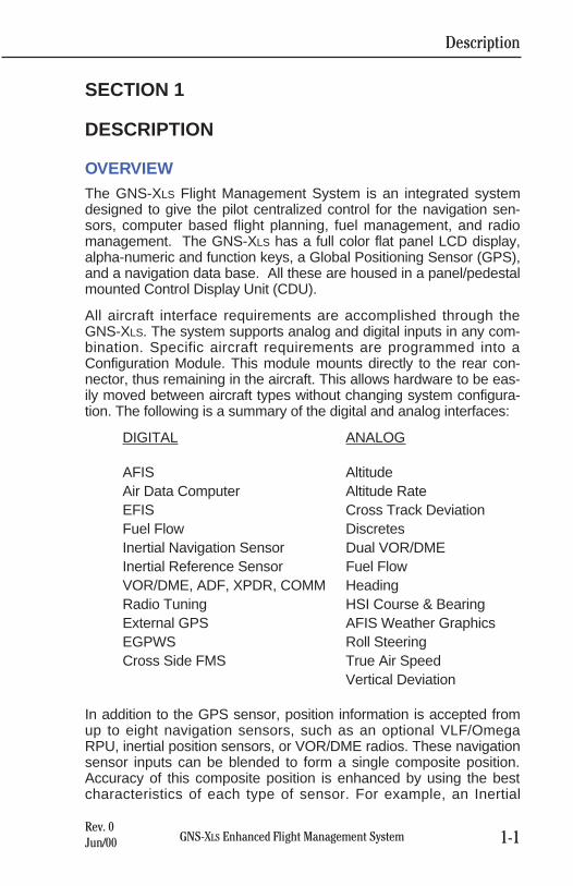
OVERVIEWThe GNS-XLS Flight Management System is an integrated systemdesigned to give the pilot centralized control for the navigation sen-sors, computer based flight planning, fuel management, and radiomanagement. The GNS-XLS has a full color flat panel LCD display,alpha-numeric and function keys, a Global Positioning Sensor (GPS),and a navigation data base. All these are housed in a panel/pedestalmounted Control Display Unit (CDU).
All aircraft interface requirements are accomplished through theGNS-XLS. The system supports analog and digital inputs in any com-bination. Specific aircraft requirements are programmed into aConfiguration Module. This module mounts directly to the rear con-nector, thus remaining in the aircraft. This allows hardware to be eas-ily moved between aircraft types without changing system configura-tion. The following is a summary of the digital and analog interfaces:
DIGITAL ANALOG
AFIS AltitudeAir Data Computer Altitude RateEFIS Cross Track DeviationFuel Flow DiscretesInertial Navigation Sensor Dual VOR/DMEInertial Reference Sensor Fuel FlowVOR/DME, ADF, XPDR, COMM HeadingRadio Tuning HSI Course & BearingExternal GPS AFIS Weather GraphicsEGPWS Roll SteeringCross Side FMS True Air Speed
Vertical Deviation
In addition to the GPS sensor, position information is accepted fromup to eight navigation sensors, such as an optional VLF/OmegaRPU, inertial position sensors, or VOR/DME radios. These navigationsensor inputs can be blended to form a single composite position.Accuracy of this composite position is enhanced by using the bestcharacteristics of each type of sensor. For example, an Inertial
Description
1-1GNS-XLS Enhanced Flight Management SystemRev. 0Jun/00
Reference System (IRS) has excellent short term characteristicswhile VLF/Omega has excellent long term stability. The internal GPSsensor has excellent overall characteristics and will usually be thedominant sensor during blending. However, when RAIM is available,the GPS sensor is the sole contributor to the composite position.
NOTE: RAIM (Receiver Autonomous Integrity Monitoring) is a quali-ty factor used to determine the accuracy of the GPS position. It is aninternal function of the GPS receiver and determines the accuracy ofit’s navigation solution.
The navigation data base is updated on a 28-day cycle by way of amemory card. This card is inserted in a Personal Computer MemoryCard International Association (PCMCIA) slot located under the lowerportion of the alpha keyboard. This worldwide database containsover 50,000 waypoints, navaids and airports. It also contains alti-tudes at appropriate waypoints, SID, STAR, AIRWAY, andAPPROACH procedures. In addition to this database, the memorycan store up to 999 operator generated waypoints. Individual naviga-tion points can be organized into 56 different stored flight plans, eachcontaining up to 50 waypoints.
Due to the way the GNS-XLS database is structured, waypoints musthave unique identifiers. However, some duplicate ICAO identifiersexist for more than one waypoint. In these cases the waypoint identi-fiers are renamed in the database. Two naming conventions areused, one for four character identifiers and one for five characteridentifiers.
Four character waypoints keep the first four characters and the lasttwo characters of the ICAO airport identifier as shown in the followingexample.
MA11 at KPRC becomes MA11RC in the database.
Five character waypoints keep the first five characters and add thelast character of the ICAO airport identifier as shown in the followingexample.
MA27L at KOAK becomes MA27LK in the database.
Additional capabilities of the GNS-XLS include direct navigation frompresent position to any waypoint, and data crossfill capability for dualinstallations. Trip Plan and Fuel Plan functions are also available.There is capability for creating a PSEUDO-VORTAC (selectedcourse) to any waypoint and establishing an offset parallel course.NAVs, COMMs, ADFs and transponders can be tuned through thesystem or by using the individual control heads.
Description
1-2 GNS-XLS Enhanced Flight Management SystemRev. 0Jun/00
GENERAL TERMSFIELD: A line of information.
CURSOR: Yellow rectangular box placed over a field to enter orchange the information in that field. The cursor is nor-mally out of view unless brought into view by depressingthe Line Select Keys on either side of the screen. Wheninformation is entered into a field and the ENTER Key isdepressed, the cursor will move to the next enterablefield or disappear from the screen when the last field isentered. Blinking of a field indicates that the computerhas not accepted the entry because of unreasonable orinvalid information.
PAGE: Information is arranged in sections and subsectionsmuch like chapters in a book. Individual screen displaysare referred to as pages. Each section is selected bydepressing the appropriate Display Selector Key locatedat the top of the GNS-XLS. Each subsequent push of thekey will select the next page of that section. A subsec-tion page is selected by depressing the Line Select Keynext to the topic desired, then depressing the ENTERKey. The PRV, NXT, or BACK Key can be used tomove forward or backward through pages of a subsec-tion. If the first page of a subsection is displayed, theBACK Key will exit the subsection.
WAYPOINT:A navigation point consisting of 1 to 6 alpha, numericcharacters that has a specific latitude and longitude.
Description
1-3GNS-XLS Enhanced Flight Management SystemRev. 0Jun/00
CONTROLS AND INDICATORS
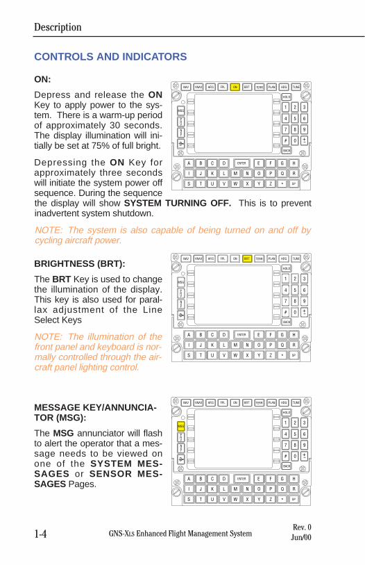
ON:
Depress and release the ONKey to apply power to the sys-tem. There is a warm-up periodof approximately 30 seconds.The display illumination will ini-tially be set at 75% of full bright.
Depressing the ON Key forapproximately three secondswill initiate the system power offsequence. During the sequencethe display will show SYSTEM TURNING OFF. This is to preventinadvertent system shutdown.
NOTE: The system is also capable of being turned on and off bycycling aircraft power.
BRIGHTNESS (BRT):
The BRT Key is used to changethe illumination of the display.This key is also used for paral-lax adjustment of the LineSelect Keys
NOTE: The illumination of thefront panel and keyboard is nor-mally controlled through the air-craft panel lighting control.
MESSAGE KEY/ANNUNCIA -TOR (MSG):
The MSG annunciator will flashto alert the operator that a mes-sage needs to be viewed onone of the SYSTEM MES-SAGES or SENSOR MES-SAGES Pages.
Description
1-4 GNS-XLS Enhanced Flight Management SystemRev. 0Jun/00
NAV
MSG
PRV
NXT
VNAV AFIS FPL ON BRT PLAN HDG TUNE
HOLD
BACK
ENTER
SP
1 2 3
4 5 6
7 8 9
# 0
A B
D
C D E F G H
I J K L
S T U V
M N O P
W X Y Z
Q R
*
TERR
NAV
MSG
PRV
NXT
VNAV AFIS FPL ON BRT PLAN HDG TUNE
HOLD
BACK
ENTER
SP
1 2 3
4 5 6
7 8 9
# 0
A B
D
C D E F G H
I J K L
S T U V
M N O P
W X Y Z
Q R
*
TERR
NAV
MSG
PRV
NXT
VNAV AFIS FPL ON BRT PLAN HDG TUNE
HOLD
BACK
ENTER
SP
1 2 3
4 5 6
7 8 9
# 0
A B
D
C D E F G H
I J K L
S T U V
M N O P
W X Y Z
Q R
*
TERR
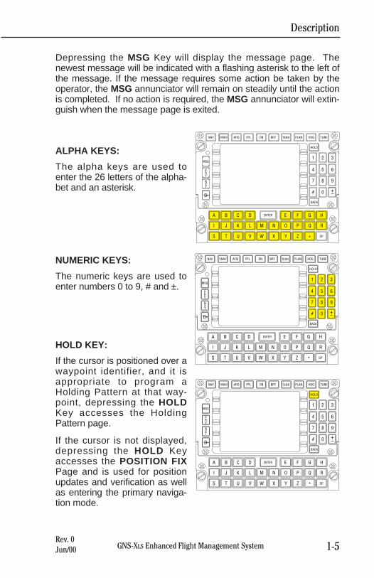
Depressing the MSG Key will display the message page. Thenewest message will be indicated with a flashing asterisk to the left ofthe message. If the message requires some action be taken by theoperator, the MSG annunciator will remain on steadily until the actionis completed. If no action is required, the MSG annunciator will extin-guish when the message page is exited.
ALPHA KEYS:
The alpha keys are used toenter the 26 letters of the alpha-bet and an asterisk.
NUMERIC KEYS:
The numeric keys are used toenter numbers 0 to 9, # and ±.
HOLD KEY:
If the cursor is positioned over awaypoint identifier, and it isappropriate to program aHolding Pattern at that way-point, depressing the HOLDKey accesses the HoldingPattern page.
If the cursor is not displayed,depressing the HOLD Keyaccesses the POSITION FIXPage and is used for positionupdates and verification as wellas entering the primary naviga-tion mode.
Description
1-5GNS-XLS Enhanced Flight Management SystemRev. 0Jun/00
NAV
MSG
PRV
NXT
VNAV AFIS FPL ON BRT PLAN HDG TUNE
HOLD
BACK
ENTER
SP
1 2 3
4 5 6
7 8 9
# 0
A B
D
C D E F G H
I J K L
S T U V
M N O P
W X Y Z
Q R
**
TERR
NAV
MSG
PRV
NXT
VNAV AFIS FPL ON BRT PLAN HDG TUNE
HOLD
BACK
ENTER
SP
1 2 3
4 5 6
7 8 9
# 0
A B
D
C D E F G H
I J K L
S T U V
M N O P
W X Y Z
Q R
*
TERR
NAV
MSG
PRV
NXT
VNAV AFIS FPL ON BRT PLAN HDG TUNE
HOLD
BACK
ENTER
SP
1 2 3
4 5 6
7 8 9
# 0
A B
D
C D E F G H
I J K L
S T U V
M N O P
W X Y Z
Q R
*
TERR
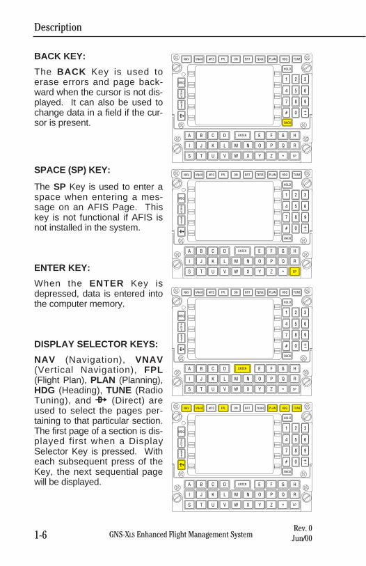
BACK KEY:
The BACK Key is used toerase errors and page back-ward when the cursor is not dis-played. It can also be used tochange data in a field if the cur-sor is present.
SPACE (SP) KEY:
The SP Key is used to enter aspace when entering a mes-sage on an AFIS Page. Thiskey is not functional if AFIS isnot installed in the system.
ENTER KEY:
When the ENTER Key isdepressed, data is entered intothe computer memory.
DISPLAY SELECTOR KEYS:
NAV (Navigation), VNAV(Vertical Navigation), FPL(Flight Plan), PLAN (Planning),HDG (Heading), TUNE (RadioTuning), and d (Direct) areused to select the pages per-taining to that particular section.The first page of a section is dis-played first when a DisplaySelector Key is pressed. Witheach subsequent press of theKey, the next sequential pagewill be displayed.
Description
1-6 GNS-XLS Enhanced Flight Management SystemRev. 0Jun/00
NAV
MSG
PRV
NXT
VNAV AFIS FPL ON BRT PLAN HDG TUNE
HOLD
BACK
ENTER
SP
1 2 3
4 5 6
7 8 9
# 0
A B
D
C D E F G H
I J K L
S T U V
M N O P
W X Y Z
Q R
*
TERR
NAV
MSG
PRV
NXT
VNAV AFIS FPL ON BRT PLAN HDG TUNE
HOLD
BACK
ENTER
SP
1 2 3
4 5 6
7 8 9
# 0
A B
D
C D E F G H
I J K L
S T U V
M N O P
W X Y Z
Q R
*
TERR
NAV
MSG
PRV
NXT
VNAV AFIS FPL ON BRT PLAN HDG TUNE
HOLD
BACK
ENTER
SP
1 2 3
4 5 6
7 8 9
# 0
A B
D
C D E F G H
I J K L
S T U V
M N O P
W X Y Z
Q R
*
TERR
NAV
MSG
PRV
NXT
VNAV AFIS FPL ON BRT PLAN HDG TUNE
HOLD
BACK
ENTER
SP
1 2 3
4 5 6
7 8 9
# 0
A B
D
C D E F G H
I J K L
S T U V
M N O P
W X Y Z
Q R
*
TERR
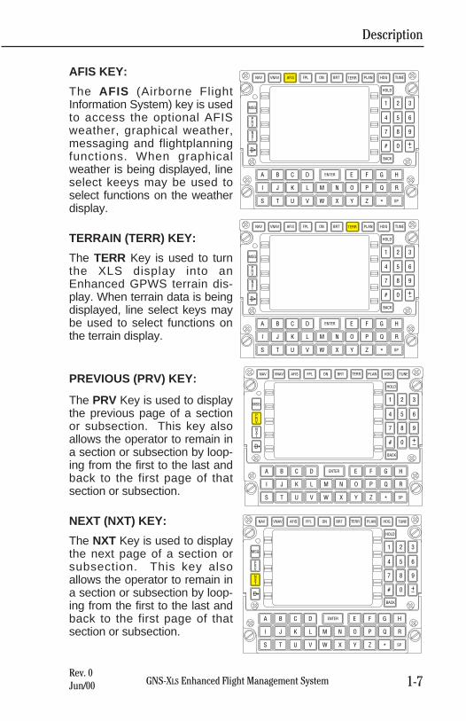
AFIS KEY:
The AFIS (Airborne FlightInformation System) key is usedto access the optional AFISweather, graphical weather,messaging and flightplanningfunctions. When graphicalweather is being displayed, lineselect keeys may be used toselect functions on the weatherdisplay.
TERRAIN (TERR) KEY:
The TERR Key is used to turnthe XLS display into anEnhanced GPWS terrain dis-play. When terrain data is beingdisplayed, line select keys maybe used to select functions onthe terrain display.
PREVIOUS (PRV) KEY:
The PRV Key is used to displaythe previous page of a sectionor subsection. This key alsoallows the operator to remain ina section or subsection by loop-ing from the first to the last andback to the first page of thatsection or subsection.
NEXT (NXT) KEY:
The NXT Key is used to displaythe next page of a section orsubsection. This key alsoallows the operator to remain ina section or subsection by loop-ing from the first to the last andback to the first page of thatsection or subsection.
Description
1-7GNS-XLS Enhanced Flight Management SystemRev. 0Jun/00
NAV
MSG
PRV
NXT
VNAV AFIS FPL ON BRT PLAN HDG TUNE
HOLD
BACK
ENTER
SP
1 2 3
4 5 6
7 8 9
# 0
A B
D
C D E F G H
I J K L
S T U V
M N O P
W X Y Z
Q R
*
TERR
NAV
MSG
PRV
NXT
VNAV AFIS FPL ON BRT PLAN HDG TUNE
HOLD
BACK
ENTER
SP
1 2 3
4 5 6
7 8 9
# 0
A B
D
C D E F G H
I J K L
S T U V
M N O P
W X Y Z
Q R
*
TERR
NAV
MSG
PRV
NXT
VNAV AFIS FPL ON BRT PLAN HDG TUNE
HOLD
BACK
ENTER
SP
1 2 3
4 5 6
7 8 9
# 0
A B
D
C D E F G H
I J K L
S T U V
M N O P
W X Y Z
Q R
*
TERR
NAV
MSG
PRV
NXT
VNAV AFIS FPL ON BRT PLAN HDG TUNE
HOLD
BACK
ENTER
SP
1 2 3
4 5 6
7 8 9
# 0
A B
D
C D E F G H
I J K L
S T U V
M N O P
W X Y Z
Q R
*
TERR
Rev. 0Jun/00
Description
1-8 GNS-XLS Enhanced Flight Management System
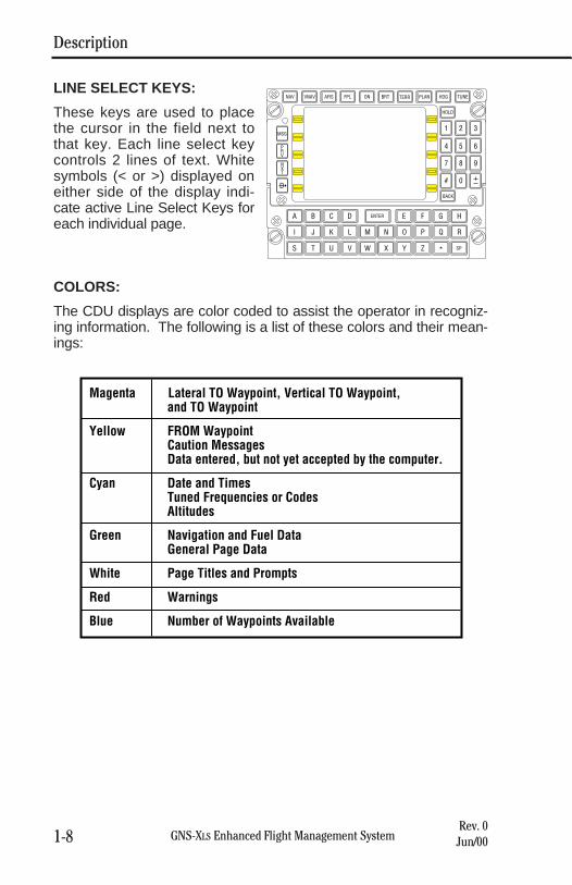
Magenta Lateral TO Waypoint, Vertical TO Waypoint, and TO Waypoint
Yellow FROM WaypointCaution MessagesData entered, but not yet accepted by the computer.
Cyan Date and TimesTuned Frequencies or CodesAltitudes
Green Navigation and Fuel DataGeneral Page Data
White Page Titles and Prompts
Red Warnings
Blue Number of Waypoints Available
LINE SELECT KEYS:
These keys are used to placethe cursor in the field next tothat key. Each line select keycontrols 2 lines of text. Whitesymbols (< or >) displayed oneither side of the display indi-cate active Line Select Keys foreach individual page.
COLORS:
The CDU displays are color coded to assist the operator in recogniz-ing information. The following is a list of these colors and their mean-ings:
NAV
MSG
PRV
NXT
VNAV AFIS FPL ON BRT PLAN HDG TUNE
HOLD
BACK
ENTER
SP
1 2 3
4 5 6
7 8 9
# 0
A B
D
C D E F G H
I J K L
S T U V
M N O P
W X Y Z
Q R
*
TERR
Page Display Definitions
2-1GNS-XLS Enhanced Flight Management SystemRev. 0Jun/00
SECTION 2
PAGE DISPLAY DEFINITIONSThe following section contains definitions pertaining to informationand format seen when a particular function key is depressed.
PAGE DISPLAYS AT POWER-UPFor a better understanding of the GNS-XLS functions, this sectionshould be reviewed prior to operating the system.
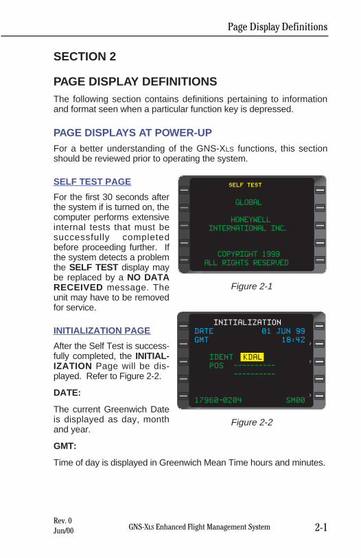
SELF TEST PAGE
For the first 30 seconds afterthe system if is turned on, thecomputer performs extensiveinternal tests that must besuccessfully completedbefore proceeding further. Ifthe system detects a problemthe SELF TEST display maybe replaced by a NO DATARECEIVED message. Theunit may have to be removedfor service.
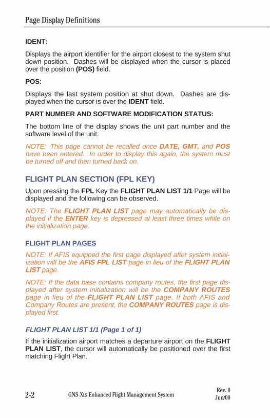
INITIALIZATION PAGE
After the Self Test is success-fully completed, the INITIAL-IZATION Page will be dis-played. Refer to Figure 2-2.
DATE:
The current Greenwich Dateis displayed as day, monthand year.
GMT:
Time of day is displayed in Greenwich Mean Time hours and minutes.
SELF TEST
GLOBAL
HONEYWELL
INTERNATIONAL INC.
COPYRIGHT 1999
ALL RIGHTS RESERVED
Figure 2-1
DATE 01 JUN 99
GMT 18:42
IDENT KDAL
POS ----------
----------
17960-0204 SM00
INITIALIZATION
>
>
>
Figure 2-2
Page Display Definitions
2-2 GNS-XLS Enhanced Flight Management SystemRev. 0Jun/00
IDENT:
Displays the airport identifier for the airport closest to the system shutdown position. Dashes will be displayed when the cursor is placedover the position (POS) field.
POS:
Displays the last system position at shut down. Dashes are dis-played when the cursor is over the IDENT field.
PART NUMBER AND SOFTWARE MODIFICATION STATUS:
The bottom line of the display shows the unit part number and thesoftware level of the unit.
NOTE: This page cannot be recalled once DATE, GMT, and POShave been entered. In order to display this again, the system mustbe turned off and then turned back on.
FLIGHT PLAN SECTION (FPL KEY)Upon pressing the FPL Key the FLIGHT PLAN LIST 1/1 Page will bedisplayed and the following can be observed.
NOTE: The FLIGHT PLAN LIST page may automatically be dis-played if the ENTER key is depressed at least three times while onthe initialization page.
FLIGHT PLAN PAGES
NOTE: If AFIS equipped the first page displayed after system initial-ization will be the AFIS FPL LIST page in lieu of the FLIGHT PLANLIST page.
NOTE: If the data base contains company routes, the first page dis-played after system initialization will be the COMPANY ROUTESpage in lieu of the FLIGHT PLAN LIST page. If both AFIS andCompany Routes are present, the COMPANY ROUTES page is dis-played first.
FLIGHT PLAN LIST 1/1 (Page 1 of 1)
If the initialization airport matches a departure airport on the FLIGHTPLAN LIST , the cursor will automatically be positioned over the firstmatching Flight Plan.
Page Display Definitions
2-3GNS-XLS Enhanced Flight Management SystemRev. 0Jun/00
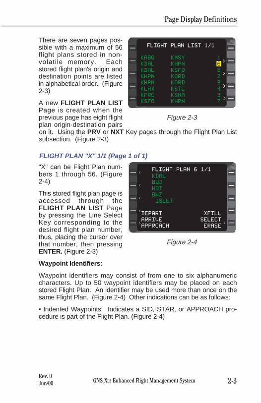
There are seven pages pos-sible with a maximum of 56flight plans stored in non-volatile memory. Eachstored flight plan's origin anddestination points are listedin alphabetical order. (Figure2-3)
A new FLIGHT PLAN LISTPage is created when theprevious page has eight flightplan origin-destination pairson it. Using the PRV or NXT Key pages through the Flight Plan Listsubsection. (Figure 2-3)
FLIGHT PLAN "X" 1/1 (Page 1 of 1)
"X" can be Flight Plan num-bers 1 through 56. (Figure 2-4)
This stored flight plan page isaccessed through theFLIGHT PLAN LIST Pageby pressing the Line SelectKey corresponding to thedesired flight plan number,thus, placing the cursor overthat number, then pressingENTER. (Figure 2-3)
Waypoint Identifiers:
Waypoint identifiers may consist of from one to six alphanumericcharacters. Up to 50 waypoint identifiers may be placed on eachstored Flight Plan. An identifier may be used more than once on thesame Flight Plan. (Figure 2-4) Other indications can be as follows:
• Indented Waypoints: Indicates a SID, STAR, or APPROACH pro-cedure is part of the Flight Plan. (Figure 2-4)
KABQ KMSY 1
KDAL KHPN 6
KDAL KSFO 8
KHPN KORD 2
KHPN KORD 9
KLAX KSTL 4
KPRC KSNA 3
KSFO KHPN 7
FLIGHT PLAN LIST 1/1
>
>
>
>
Figure 2-3
KDAL
BUJ
HOT
BWZ
ISLET
DEPART XFILL
ARRIVE SELECT
APPROACH ERASE
FLIGHT PLAN 6 1/1
<
<
<
<
<
<
Figure 2-4
Page Display Definitions
2-4 GNS-XLS Enhanced Flight Management SystemRev. 0Jun/00
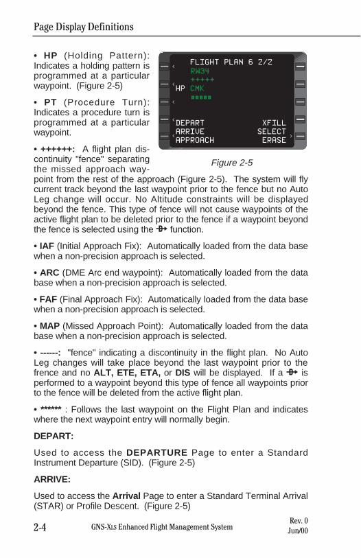
• HP (Holding Pattern):Indicates a holding pattern isprogrammed at a particularwaypoint. (Figure 2-5)
• PT (Procedure Turn):Indicates a procedure turn isprogrammed at a particularwaypoint.
• ++++++: A flight plan dis-continuity "fence" separatingthe missed approach way-point from the rest of the approach (Figure 2-5). The system will flycurrent track beyond the last waypoint prior to the fence but no AutoLeg change will occur. No Altitude constraints will be displayedbeyond the fence. This type of fence will not cause waypoints of theactive flight plan to be deleted prior to the fence if a waypoint beyondthe fence is selected using the d function.
• IAF (Initial Approach Fix): Automatically loaded from the data basewhen a non-precision approach is selected.
• ARC (DME Arc end waypoint): Automatically loaded from the database when a non-precision approach is selected.
• FAF (Final Approach Fix): Automatically loaded from the data basewhen a non-precision approach is selected.
• MAP (Missed Approach Point): Automatically loaded from the database when a non-precision approach is selected.
• ------: "fence" indicating a discontinuity in the flight plan. No AutoLeg changes will take place beyond the last waypoint prior to thefrence and no ALT, ETE, ETA, or DIS will be displayed. If a d isperformed to a waypoint beyond this type of fence all waypoints priorto the fence will be deleted from the active flight plan.
• ****** : Follows the last waypoint on the Flight Plan and indicateswhere the next waypoint entry will normally begin.
DEPART:
Used to access the DEPARTURE Page to enter a StandardInstrument Departure (SID). (Figure 2-5)
ARRIVE:
Used to access the Arrival Page to enter a Standard Terminal Arrival(STAR) or Profile Descent. (Figure 2-5)
RW34
+++++
HP CMK
#####
DEPART XFILL
ARRIVE SELECT
APPROACH ERASE
FLIGHT PLAN 6 2/2
<
<
<
<
<
<
Figure 2-5
Page Display Definitions
2-5GNS-XLS Enhanced Flight Management SystemRev. 0Jun/00
APPROACH:
Used to access the APPROACH Page to enter a non-precisionapproach. (Figure 2-5)
XFILL: Used to transfer information between systems in a dual sys-tem installation. In a single system installation, this prompt will not bedisplayed.
SELECT or INVERT:
Used to transfer a Stored Flight Plan to the ACTIVE FLIGHT PLANPage. Depressing the BACK Key when the cursor is over this fieldbrings up INVERT?, which is used to transfer the waypoints of aStored Flight Plan to the ACTIVE FLIGHT PLAN Page in reverseorder. (Figure 2-5)
ERASE:
Used to clear an entire flight plan. (Figure 2-5)
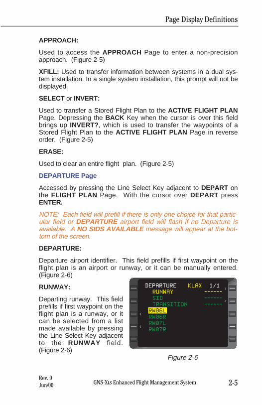
DEPARTURE Page
Accessed by pressing the Line Select Key adjacent to DEPART onthe FLIGHT PLAN Page. With the cursor over DEPART pressENTER.
NOTE: Each field will prefill if there is only one choice for that partic-ular field or DEPARTURE airport field will flash if no Departure isavailable. A NO SIDS AVAILABLE message will appear at the bot-tom of the screen.
DEPARTURE:
Departure airport identifier. This field prefills if first waypoint on theflight plan is an airport or runway, or it can be manually entered.(Figure 2-6)
RUNWAY:
Departing runway. This fieldprefills if first waypoint on theflight plan is a runway, or itcan be selected from a listmade available by pressingthe Line Select Key adjacentto the RUNWAY field.(Figure 2-6)
<
RUNWAY ------
SID ------
TRANSITION ------
RW06L
RW06R
RW07L
RW07R
` erase
DEPARTURE KLAX 1/1
<
<
<
Figure 2-6
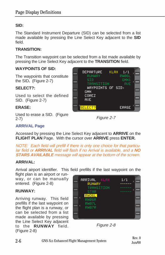
Page Display Definitions
2-6 GNS-XLS Enhanced Flight Management SystemRev. 0Jun/00
SID:
The Standard Instrument Departure (SID) can be selected from a listmade available by pressing the Line Select Key adjacent to the SIDfield.
TRANSITION:
The Transition waypoint can be selected from a list made available bypressing the Line Select Key adjacent to the TRANSITION field.
WAYPOINTS OF SID:
The waypoints that constitutethe SID. (Figure 2-7)
SELECT?:
Used to select the definedSID. (Figure 2-7)
ERASE:
Used to erase a SID. (Figure2-7)
ARRIVAL Page
Accessed by pressing the Line Select Key adjacent to ARRIVE on theFLIGHT PLAN Page. With the cursor over ARRIVE press ENTER.
NOTE: Each field will prefill if there is only one choice for that particu-lar field or ARRIVAL field will flash if no Arrival is available, and a NOSTARS AVAILABLE message will appear at the bottom of the screen.
ARRIVAL:
Arrival airport identifier. This field prefills if the last waypoint on theflight plan is an airport or run-way, or can be manuallyentered. (Figure 2-8)
RUNWAY:
Arriving runway. This fieldprefills if the last waypoint onthe flight plan is a runway, orcan be selected from a listmade available by pressingthe Line Select Key adjacentto the RUNWAY field.(Figure 2-8)
<
RUNWAY RW06L
SID GMN1
TRANSITION AVE
WAYPOINTS OF SID:
GMN
COREZ
AVE
SELECT? ` eraseERASE
DEPARTURE KLAX 1/1
<
<
<
Figure 2-7
<
RUNWAY ------
TRANSITION ------
STAR ------
RWO6L
RW06R
RW07L
RW07R
ARRIVAL KLAX 1/1
<
<
<
Figure 2-8
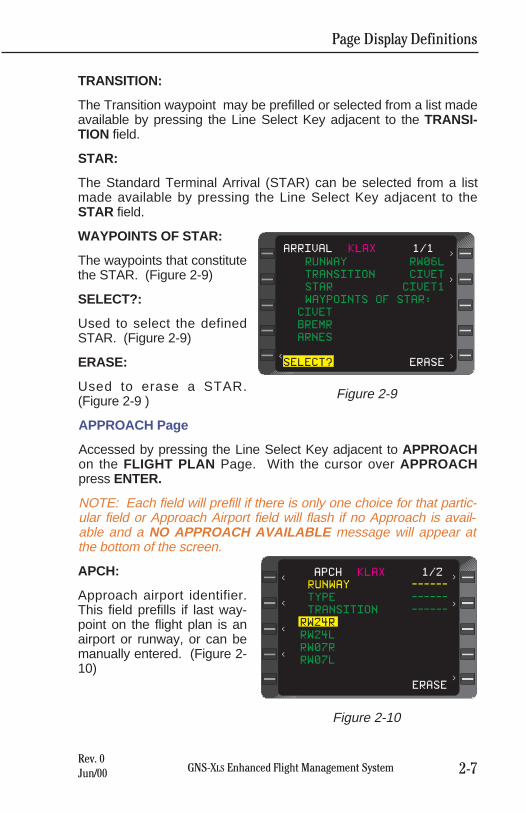
Page Display Definitions
2-7GNS-XLS Enhanced Flight Management SystemRev. 0Jun/00
TRANSITION:
The Transition waypoint may be prefilled or selected from a list madeavailable by pressing the Line Select Key adjacent to the TRANSI-TION field.
STAR:
The Standard Terminal Arrival (STAR) can be selected from a listmade available by pressing the Line Select Key adjacent to theSTAR field.
WAYPOINTS OF STAR:
The waypoints that constitutethe STAR. (Figure 2-9)
SELECT?:
Used to select the definedSTAR. (Figure 2-9)
ERASE:
Used to erase a STAR.(Figure 2-9 )
APPROACH Page
Accessed by pressing the Line Select Key adjacent to APPROACHon the FLIGHT PLAN Page. With the cursor over APPROACHpress ENTER.
NOTE: Each field will prefill if there is only one choice for that partic-ular field or Approach Airport field will flash if no Approach is avail-able and a NO APPROACH AVAILABLE message will appear atthe bottom of the screen.
APCH:
Approach airport identifier.This field prefills if last way-point on the flight plan is anairport or runway, or can bemanually entered. (Figure 2-10)
<
RUNWAY RW06L
TRANSITION CIVET
STAR CIVET1
WAYPOINTS OF STAR:
CIVET
BREMR
ARNES
SELECT? ERASE
ARRIVAL KLAX 1/1
<
<
<
Figure 2-9
<
RUNWAY ------
TYPE ------
TRANSITION ------
RW24R
RW24L
RW07R
RW07L
` eraseERASE
APCH KLAX 1/2
<
<
<
<
<
<
Figure 2-10
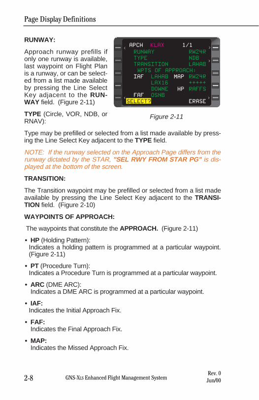
RUNWAY:
Approach runway prefills ifonly one runway is available,last waypoint on Flight Planis a runway, or can be select-ed from a list made availableby pressing the Line SelectKey adjacent to the RUN-WAY field. (Figure 2-11)
TYPE (Circle, VOR, NDB, orRNAV):
Type may be prefilled or selected from a list made available by press-ing the Line Select Key adjacent to the TYPE field.
NOTE: If the runway selected on the Approach Page differs from therunway dictated by the STAR, "SEL RWY FROM STAR PG" is dis-played at the bottom of the screen.
TRANSITION:
The Transition waypoint may be prefilled or selected from a list madeavailable by pressing the Line Select Key adjacent to the TRANSI-TION field. (Figure 2-10)
WAYPOINTS OF APPROACH:
The waypoints that constitute the APPROACH. (Figure 2-11)
• HP (Holding Pattern):Indicates a holding pattern is programmed at a particular waypoint.(Figure 2-11)
• PT (Procedure Turn):Indicates a Procedure Turn is programmed at a particular waypoint.
• ARC (DME ARC):Indicates a DME ARC is programmed at a particular waypoint.
• IAF:Indicates the Initial Approach Fix.
• FAF:Indicates the Final Approach Fix.
• MAP:Indicates the Missed Approach Fix.
Page Display Definitions
2-8 GNS-XLS Enhanced Flight Management SystemRev. 0Jun/00
<
RUNWAY RW24R
TYPE NDB
TRANSITION LAHAB
WPTS OF APPROACH:
IAF LAHAB MAP RW24R
LAX16 +++++
DOWNE HP RAFFS
FAF OSNB
SELECT?erase ERASE
APCH KLAX 1/1< <
<
<
Figure 2-11
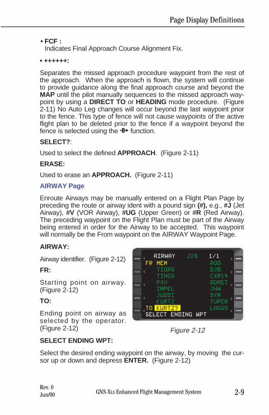
Page Display Definitions
2-9GNS-XLS Enhanced Flight Management SystemRev. 0Jun/00
• FCF :Indicates Final Approach Course Alignment Fix.
• ++++++:
Separates the missed approach procedure waypoint from the rest ofthe approach. When the approach is flown, the system will continueto provide guidance along the final approach course and beyond theMAP until the pilot manually sequences to the missed approach way-point by using a DIRECT TO or HEADING mode procedure. (Figure2-11) No Auto Leg changes will occur beyond the last waypoint priorto the fence. This type of fence will not cause waypoints of the activeflight plan to be deleted prior to the fence if a waypoint beyond thefence is selected using the d function.
SELECT? :
Used to select the defined APPROACH . (Figure 2-11)
ERASE:
Used to erase an APPROACH. (Figure 2-11)
AIRWAY Page
Enroute Airways may be manually entered on a Flight Plan Page bypreceding the route or airway ident with a pound sign (#), e.g., #J (JetAirway), #V (VOR Airway), #UG (Upper Green) or #R (Red Airway).The preceding waypoint on the Flight Plan must be part of the Airwaybeing entered in order for the Airway to be accepted. This waypointwill normally be the From waypoint on the AIRWAY Waypoint Page.
AIRWAY:
Airway identifier. (Figure 2-12)
FR:
Starting point on airway.(Figure 2-12)
TO:
Ending point on airway asselected by the operator.(Figure 2-12)
SELECT ENDING WPT:
Select the desired ending waypoint on the airway, by moving the cur-sor up or down and depress ENTER. (Figure 2-12)
FR MEM ROD
TIGRS DJB
TINGS CXR14
PXV DORET
IMPEL JHW
JUDDI SYR
KURTZ TUPER
TO KURTZ? LAGGS
SELECT ENDING WPT<
<
<
<
<
AIRWAY J29 1/1
<
<
<
<
<
Figure 2-12
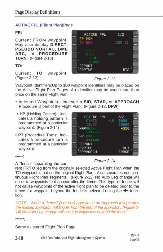
Page Display Definitions
2-10 GNS-XLS Enhanced Flight Management SystemRev. 0Jun/00
ACTIVE FPL (Flight Plan)Page
FR:
Current FROM waypoint.May also display DIRECT,PSEUDO VORTAC, DMEARC, or PROCEDURETURN. (Figure 2-13)
TO:
Current TO waypoint.(Figure 2-13)
Waypoint Identifiers:Up to 100 waypoint identifiers may be placed onthe Active Flight Plan Pages. An identifier may be used more thanonce on the same Flight Plan.
• Indented Waypoints: indicate a SID, STAR, or APPROACHProcedure is part of the Flight Plan. (Figure 2-13, DFW)
• HP (Holding Pattern): indi-cates a holding pattern isprogrammed at a particularwaypoint. (Figure 2-14)
• PT (Procedure Turn): indi-cates a procedure turn isprogrammed at a particularwaypoint.
------:
A "fence" separating the cur-rent FR/TO leg from the originally selected Active Flight Plan when theTO waypoint is not on the original Flight Plan. Also separates non-con-tinuous Flight Plan segments. (Figure 2-13) No Auto Leg change willoccur to waypoints that appear after the fence. This type of fence willnot cause waypoints of the active flight plan to be deleted prior to thefence if a waypoint beyond the fence is selected using the d func-tion.
NOTE: When a "fence" (++++++) appears in an Approach it separatesthe missed approach holding fix from the rest of the approach. (Figure 2-14) No Auto Leg change will occur to waypoints beyond the fence.
******:
Same as stored Flight Plan Page.
<
<
<
<
ACTIVE FPL 1/2
FR MEM
TO BWG 205 11
------
KDAL -CMK
DFW
KHART
DEPART
ARRIVE DIS<
Figure 2-13
<
<
<
<
ACTIVE FPL 2/2
RYMES -10 3000
ISLET 2000G
MAPRW34 435G
++++++
HP CMK
******
DEPART
ARRIVE ALT
APPROACH ERASE<
Figure 2-14
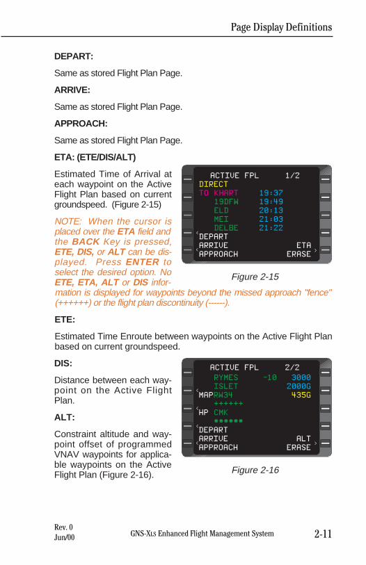
Page Display Definitions
2-11GNS-XLS Enhanced Flight Management SystemRev. 0Jun/00
DEPART:
Same as stored Flight Plan Page.
ARRIVE:
Same as stored Flight Plan Page.
APPROACH:
Same as stored Flight Plan Page.
ETA: (ETE/DIS/ALT)
Estimated Time of Arrival ateach waypoint on the ActiveFlight Plan based on currentgroundspeed. (Figure 2-15)
NOTE: When the cursor isplaced over the ETA field andthe BACK Key is pressed,ETE, DIS, or ALT can be dis-played. Press ENTER toselect the desired option. NoETE, ETA, ALT or DIS infor-mation is displayed for waypoints beyond the missed approach "fence"(++++++) or the flight plan discontinuity (------).
ETE:
Estimated Time Enroute between waypoints on the Active Flight Planbased on current groundspeed.
DIS:
Distance between each way-point on the Active FlightPlan.
ALT:
Constraint altitude and way-point offset of programmedVNAV waypoints for applica-ble waypoints on the ActiveFlight Plan (Figure 2-16).
<
<
ACTIVE FPL 1/2
DIRECT
TO KHART 19:37
19DFW 19:49
ELD 20:13
MEI 21:03
DELBE 21:22
DEPART
ARRIVE ETA
APPROACH ERASE<
Figure 2-15
<
<
<
<
ACTIVE FPL 2/2
RYMES -10 3000
ISLET 2000G
MAPRW34 435G
++++++
HP CMK
******
DEPART
ARRIVE ALT
APPROACH ERASE<
Figure 2-16
Page Display Definitions
2-12 GNS-XLS Enhanced Flight Management SystemRev. 0Jun/00
NOTE: No database altitude constraints will be displayed at the MAPif the MAP is abeam or beyond the runway threshold . No altitudeconstraints are displayed on an approach if a PT is part of theapproach procedure.
The following may appear in the waypoint altitude field:
• FL: Flight Level
• A: at or above
• B: at or below
• G: glide path (programmed Flight Path Angle)
NOTE: If an approach is programmed at the destination airport, andthe MAP is the end of the runway, the altitude value displayed next tothe MAP is approximately 50 feet above the runway threshold eleva-tion. If the MAP is prior to the end of the runway and the approach isstraight-in, the altitude displayed at the MAP is computed based on aline drawn from the FAF through the MAP to a point 50 feet abovethe runway threshold. The altitude may not be the MDA (Figure 2-16). If no approach is programmed, the altitude value will be the air-port elevation regardless of runway selection. The MAP altitude isshown in yellow.
The Waypoint VNAV offset is given in nautical miles where a nega-tive (-)offset is prior to the waypoint (Figure 2-16, interpreted as"cross ten miles before RYMES at 3000 feet") and a positive offset isafter the waypoint. If dashes appear in the altitude constraint field,NO altitude is programmed at that waypoint.
ERASE:
Same as for Stored Flight Plans except the current FROM/TO legcannot be erased. The Active Flight Plan is automatically erasedupon system shut-down.
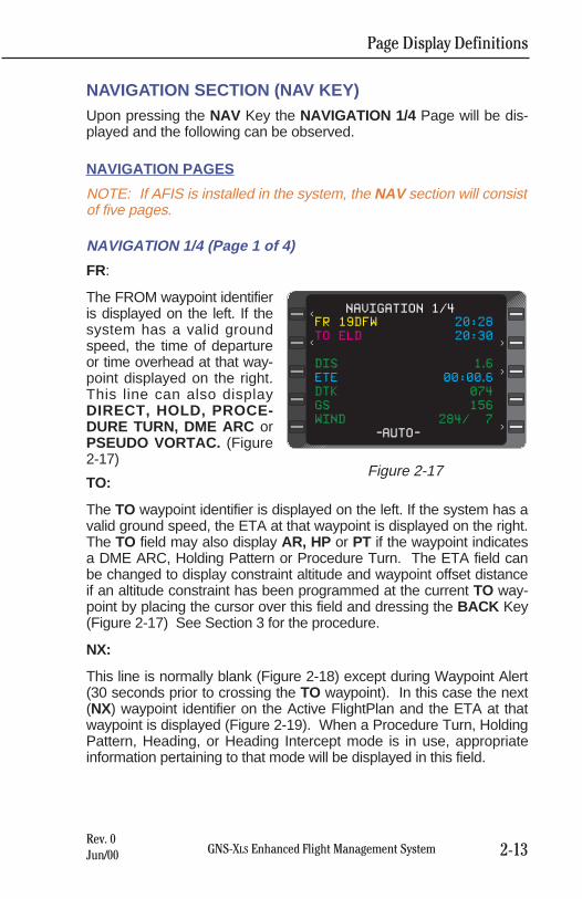
Page Display Definitions
2-13GNS-XLS Enhanced Flight Management SystemRev. 0Jun/00
NAVIGATION SECTION (NAV KEY)Upon pressing the NAV Key the NAVIGATION 1/4 Page will be dis-played and the following can be observed.
NAVIGATION PAGES
NOTE: If AFIS is installed in the system, the NAV section will consistof five pages.
NAVIGATION 1/4 (Page 1 of 4)
FR:
The FROM waypoint identifieris displayed on the left. If thesystem has a valid groundspeed, the time of departureor time overhead at that way-point displayed on the right.This line can also displayDIRECT, HOLD, PROCE-DURE TURN, DME ARC orPSEUDO VORTAC. (Figure2-17)
TO:
The TO waypoint identifier is displayed on the left. If the system has avalid ground speed, the ETA at that waypoint is displayed on the right.The TO field may also display AR, HP or PT if the waypoint indicatesa DME ARC, Holding Pattern or Procedure Turn. The ETA field canbe changed to display constraint altitude and waypoint offset distanceif an altitude constraint has been programmed at the current TO way-point by placing the cursor over this field and dressing the BACK Key(Figure 2-17) See Section 3 for the procedure.
NX:
This line is normally blank (Figure 2-18) except during Waypoint Alert(30 seconds prior to crossing the TO waypoint). In this case the next(NX) waypoint identifier on the Active FlightPlan and the ETA at thatwaypoint is displayed (Figure 2-19). When a Procedure Turn, HoldingPattern, Heading, or Heading Intercept mode is in use, appropriateinformation pertaining to that mode will be displayed in this field.
FR 19DFW 20:28
TO ELD 20:30
DIS 1.6
ETE 00:00.6
DTK 074
GS 156
WIND 284/ 7
-AUTO-
NAVIGATION 1/4<
< >
>
>
Figure 2-17
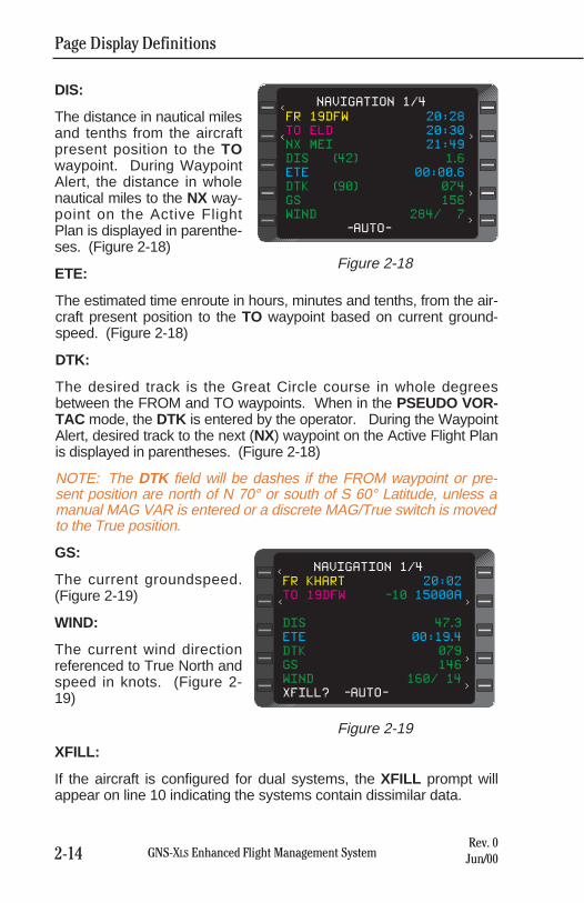
DIS:
The distance in nautical milesand tenths from the aircraftpresent position to the TOwaypoint. During WaypointAlert, the distance in wholenautical miles to the NX way-point on the Active FlightPlan is displayed in parenthe-ses. (Figure 2-18)
ETE:
The estimated time enroute in hours, minutes and tenths, from the air-craft present position to the TO waypoint based on current ground-speed. (Figure 2-18)
DTK:
The desired track is the Great Circle course in whole degreesbetween the FROM and TO waypoints. When in the PSEUDO VOR-TAC mode, the DTK is entered by the operator. During the WaypointAlert, desired track to the next (NX) waypoint on the Active Flight Planis displayed in parentheses. (Figure 2-18)
NOTE: The DTK field will be dashes if the FROM waypoint or pre-sent position are north of N 70° or south of S 60° Latitude, unless amanual MAG VAR is entered or a discrete MAG/True switch is movedto the True position.
GS:
The current groundspeed.(Figure 2-19)
WIND:
The current wind directionreferenced to True North andspeed in knots. (Figure 2-19)
XFILL:
If the aircraft is configured for dual systems, the XFILL prompt willappear on line 10 indicating the systems contain dissimilar data.
Page Display Definitions
2-14 GNS-XLS Enhanced Flight Management SystemRev. 0Jun/00
FR 19DFW 20:28
TO ELD 20:30
NX MEI 21:49
DIS (42) 1.6
ETE 00:00.6
DTK (90) 074
GS 156
WIND 284/ 7
-AUTO-
NAVIGATION 1/4<
< <
<
<
Figure 2-18
FR KHART 20:02
TO 19DFW -10 15000A
DIS 47.3
ETE 00:19.4
DTK 079
GS 146
WIND 160/ 14
XFILL? -AUTO-
NAVIGATION 1/4<
< <
<
<
Figure 2-19
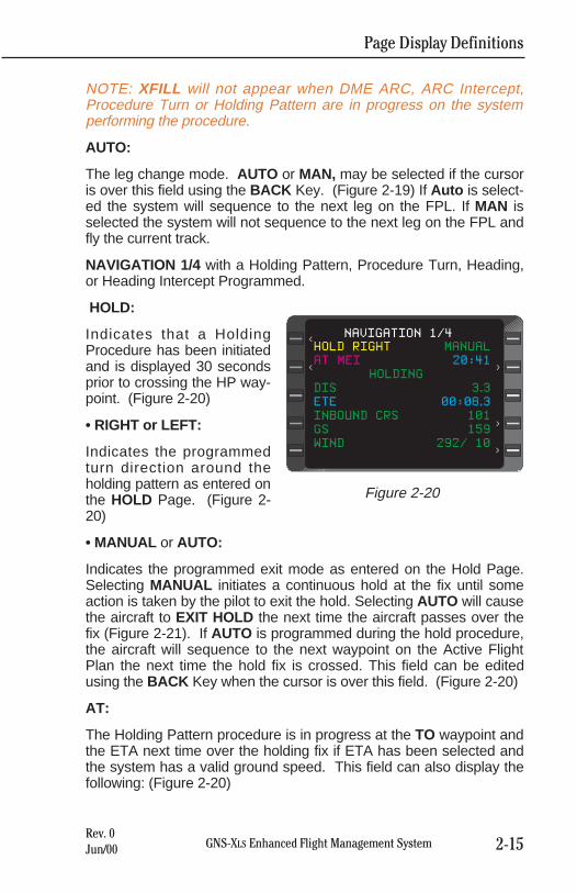
Page Display Definitions
2-15GNS-XLS Enhanced Flight Management SystemRev. 0Jun/00
NOTE: XFILL will not appear when DME ARC, ARC Intercept,Procedure Turn or Holding Pattern are in progress on the systemperforming the procedure.
AUTO:
The leg change mode. AUTO or MAN, may be selected if the cursoris over this field using the BACK Key. (Figure 2-19) If Auto is select-ed the system will sequence to the next leg on the FPL. If MAN isselected the system will not sequence to the next leg on the FPL andfly the current track.
NAVIGATION 1/4 with a Holding Pattern, Procedure Turn, Heading,or Heading Intercept Programmed.
HOLD:
Indicates that a HoldingProcedure has been initiatedand is displayed 30 secondsprior to crossing the HP way-point. (Figure 2-20)
• RIGHT or LEFT:
Indicates the programmedturn direction around theholding pattern as entered onthe HOLD Page. (Figure 2-20)
• MANUAL or AUTO:
Indicates the programmed exit mode as entered on the Hold Page.Selecting MANUAL initiates a continuous hold at the fix until someaction is taken by the pilot to exit the hold. Selecting AUTO will causethe aircraft to EXIT HOLD the next time the aircraft passes over thefix (Figure 2-21). If AUTO is programmed during the hold procedure,the aircraft will sequence to the next waypoint on the Active FlightPlan the next time the hold fix is crossed. This field can be editedusing the BACK Key when the cursor is over this field. (Figure 2-20)
AT:
The Holding Pattern procedure is in progress at the TO waypoint andthe ETA next time over the holding fix if ETA has been selected andthe system has a valid ground speed. This field can also display thefollowing: (Figure 2-20)
HOLD RIGHT MANUAL
AT MEI 20:41
HOLDING
DIS 3.3
ETE 00:08.3
INBOUND CRS 101
GS 159
WIND 292/ 10
NAVIGATION 1/4<
< <
<
<
Figure 2-20
Page Display Definitions
2-16 GNS-XLS Enhanced Flight Management SystemRev. 0Jun/00
• HP (Holding Pattern):
Indicates a holding pattern is programmed at the TO waypoint.
• PT (Procedure Turn):
Indicates a procedure turn is programmed from the database at theTO waypoint. The airplane will fly the procedure turn. The next timeover the PT waypoint, the system will sequence to the following way-point on the flight plan.
• AR (DME Arc)
Indicates a DME Arc is programmed at the TO waypoint.
HOLDING STATUS MESSAGE: (Line 4)
• DIRECT ENTRY:
Indicates the system will use a direct entry to the holding pattern.(This message appears 30 seconds prior to entering the holding pro-cedure and changes to HOLDING after crossing the fix.) (Figure 2-20)
• TEARDROP ENTRY:
Indicates the system will use a teardrop entry to the holding pattern.(This message appears 30 seconds prior to entering the hold proce-dure and changes to HOLDING after crossing the fix the secondtime.)
• PARALLEL ENTRY:
Indicates the system will use a parallel entry to the holding pattern.(This message appears 30 seconds prior to entering the hold proce-dure and changes to HOLDING after crossing the fix the secondtime.)
• HOLDING:
Normal status while holding.
• EXIT HOLD:
Indicates the system will exit the holding pattern the next time overthe holding fix. The ETE to the holding fix is also displayed.
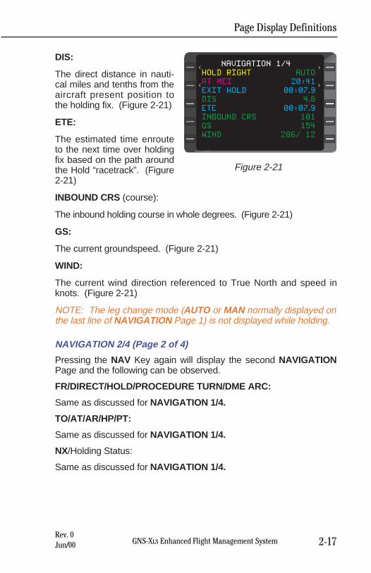
Page Display Definitions
2-17GNS-XLS Enhanced Flight Management SystemRev. 0Jun/00
DIS:
The direct distance in nauti-cal miles and tenths from theaircraft present position tothe holding fix. (Figure 2-21)
ETE:
The estimated time enrouteto the next time over holdingfix based on the path aroundthe Hold “racetrack”. (Figure2-21)
INBOUND CRS (course):
The inbound holding course in whole degrees. (Figure 2-21)
GS:
The current groundspeed. (Figure 2-21)
WIND:
The current wind direction referenced to True North and speed inknots. (Figure 2-21)
NOTE: The leg change mode (AUTO or MAN normally displayed onthe last line of NAVIGATION Page 1) is not displayed while holding.
NAVIGATION 2/4 (Page 2 of 4)
Pressing the NAV Key again will display the second NAVIGATIONPage and the following can be observed.
FR/DIRECT/HOLD/PROCEDURE TURN/DME ARC:
Same as discussed for NAVIGATION 1/4.
TO/AT/AR/HP/PT:
Same as discussed for NAVIGATION 1/4.
NX/Holding Status:
Same as discussed for NAVIGATION 1/4.
HOLD RIGHT AUTO
AT MEI 20:41
EXIT HOLD 00:07.9
DIS 4.8
ETE 00:07.9
INBOUND CRS 101
GS 154
WIND 286/ 12
NAVIGATION 1/4<
<
<
<
Figure 2-21
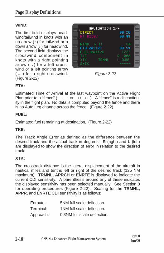
Page Display Definitions
2-18 GNS-XLS Enhanced Flight Management SystemRev. 0Jun/00
WIND:
The first field displays head-wind/tailwind in knots with anup arrow (↑) for tailwind or adown arrow (↓) for headwind.The second field displays thecrosswind component inknots with a right pointingarrow (→) for a left cross-wind or a left pointing arrow(← ) for a right crosswind.(Figure 2-22)
ETA:
Estimated Time of Arrival at the last waypoint on the Active FlightPlan prior to a “fence” (- - - - - or ++++++ ). A “fence” is a discontinu-ity in the flight plan. No data is computed beyond the fence and thereis no Auto Leg change across the fence. (Figure 2-22)
FUEL:
Estimated fuel remaining at destination. (Figure 2-22)
TKE:
The Track Angle Error as defined as the difference between thedesired track and the actual track in degrees. R (right) and L (left)are displayed to show the direction of error in relation to the desiredtrack.
XTK:
The crosstrack distance is the lateral displacement of the aircraft innautical miles and tenths left or right of the desired track (125 NMmaximum). TRMNL, APRCH or ENRTE is displayed to indicate thecurrent CDI sensitivity. A parenthesis around any of these indicatesthe displayed sensitivity has been selected manually. See Section 3for operating procedures (Figure 2-22). Scaling for the TRMNL,APPR, and ENRTE CDI sensitivity is as follows:
Enroute: 5NM full scale deflection.Terminal: 1NM full scale deflection.Approach: 0.3NM full scale deflection.
DIRECT 09:20
AT D259J 09:44
WIND % 11 8&
ETA-RW11RC 09:54
FUEL-RW11RC 1727
TKE R 008
XTK TRMNL L 0.06
SXTK ------
NAVIGATION 2/4
<
<
Figure 2-22
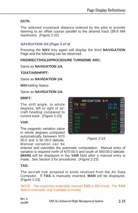
SXTK:
The selected crosstrack distance entered by the pilot to providesteering to an offset course parallel to the desired track (99.9 NMmaximum). (Figure 2-22)
NAVIGATION 3/4 (Page 3 of 4)
Pressing the NAV Key again will display the third NAVIGATIONPage and the following can be observed.
FR/DIRECT/HOLD/PROCEDURE TURN/DME ARC:
Same as NAVIGATION 1/4.
TO/AT/AR/HP/PT:
Same as NAVIGATION 1/4.
NX/Holding Status:
Same as NAVIGATION 1/4.
DRIFT:
The drift angle, in wholedegrees, left or right of air-craft heading compared tocurrent track. (Figure 2-23)
VAR:
The magnetic variation valuein whole degrees computedautomatically between N7000.0 and S 60 00.0 latitude.Manual variation can beentered and overrides the automatic computation. Manual entry ofvariation is required north of N70:00.0 and south of S60:00.0 latitude.(MAN) will be displayed in the VAR field after a manual entry ismade. See Section 3 for procedures. (Figure 2-23)
TAS:
The aircraft true airspeed in knots received from the Air DataComputer. If TAS is manually inserted, MAN will be displayed.(Figure 2-23)
NOTE: The maximum enterable manual TAS is 850 knots. The TASfield is enterable only if airdata is invalid.
Page Display Definitions
2-19GNS-XLS Enhanced Flight Management SystemRev. 0Jun/00
FR VUZ 19:36
TO VXV 20:04
DRIFT R 001
VAR (MAN) E 2
TAS 420
HDG 044
BRG 045
TK 045
NAVIGATION 3/4<
< <
<
<
Figure 2-23
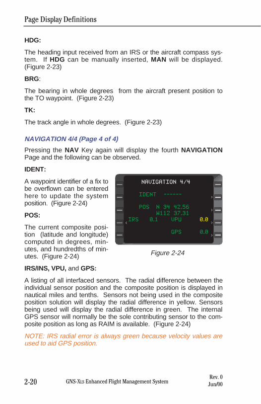
Page Display Definitions
2-20 GNS-XLS Enhanced Flight Management SystemRev. 0Jun/00
HDG:
The heading input received from an IRS or the aircraft compass sys-tem. If HDG can be manually inserted, MAN will be displayed.(Figure 2-23)
BRG:
The bearing in whole degrees from the aircraft present position tothe TO waypoint. (Figure 2-23)
TK:
The track angle in whole degrees. (Figure 2-23)
NAVIGATION 4/4 (Page 4 of 4)
Pressing the NAV Key again will display the fourth NAVIGATIONPage and the following can be observed.
IDENT:
A waypoint identifier of a fix tobe overflown can be enteredhere to update the systemposition. (Figure 2-24)
POS:
The current composite posi-tion (latitude and longitude)computed in degrees, min-utes, and hundredths of min-utes. (Figure 2-24)
IRS/INS, VPU, and GPS:
A listing of all interfaced sensors. The radial difference between theindividual sensor position and the composite position is displayed innautical miles and tenths. Sensors not being used in the compositeposition solution will display the radial difference in yellow. Sensorsbeing used will display the radial difference in green. The internalGPS sensor will normally be the sole contributing sensor to the com-posite position as long as RAIM is available. (Figure 2-24)
NOTE: IRS radial error is always green because velocity values areused to aid GPS position.
IDENT ------
POS N 34 42.56
W112 37.31
IRS 0.1 VPU 0.0
GPS 0.0
NAVIGATION 4/4
<
>
>
>
>
Figure 2-24
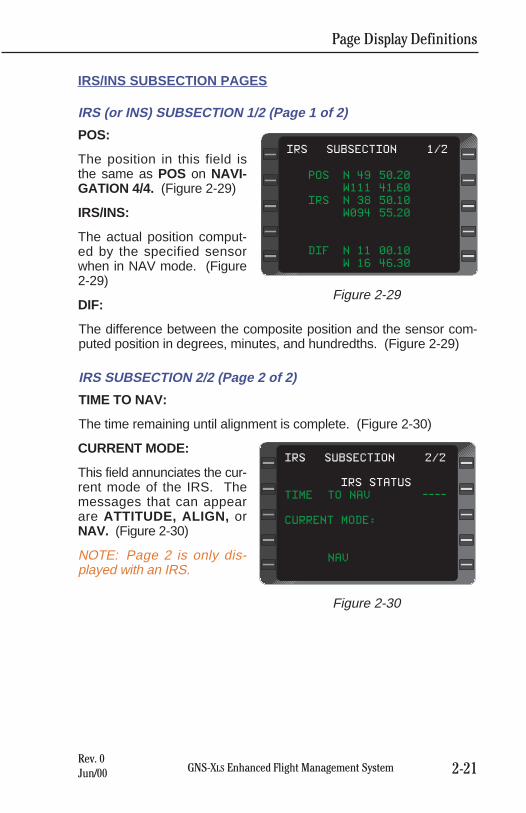
Page Display Definitions
2-21GNS-XLS Enhanced Flight Management SystemRev. 0Jun/00
IRS/INS SUBSECTION PAGES
IRS (or INS) SUBSECTION 1/2 (Page 1 of 2)
POS:
The position in this field isthe same as POS on NAVI-GATION 4/4. (Figure 2-29)
IRS/INS:
The actual position comput-ed by the specified sensorwhen in NAV mode. (Figure2-29)
DIF:
The difference between the composite position and the sensor com-puted position in degrees, minutes, and hundredths. (Figure 2-29)
IRS SUBSECTION 2/2 (Page 2 of 2)
TIME TO NAV:
The time remaining until alignment is complete. (Figure 2-30)
CURRENT MODE:
This field annunciates the cur-rent mode of the IRS. Themessages that can appearare ATTITUDE, ALIGN, orNAV. (Figure 2-30)
NOTE: Page 2 is only dis-played with an IRS.
POS N 49 50.20
W111 41.60
IRS N 38 50.10
W094 55.20
DIF` N 11 00.10
W 16 46.30
IRS SUBSECTION 1/2
Figure 2-29
IRS STATUS
TIME TO NAV ----
CURRENT MODE:
NAV
IRS SUBSECTION 2/2
Figure 2-30
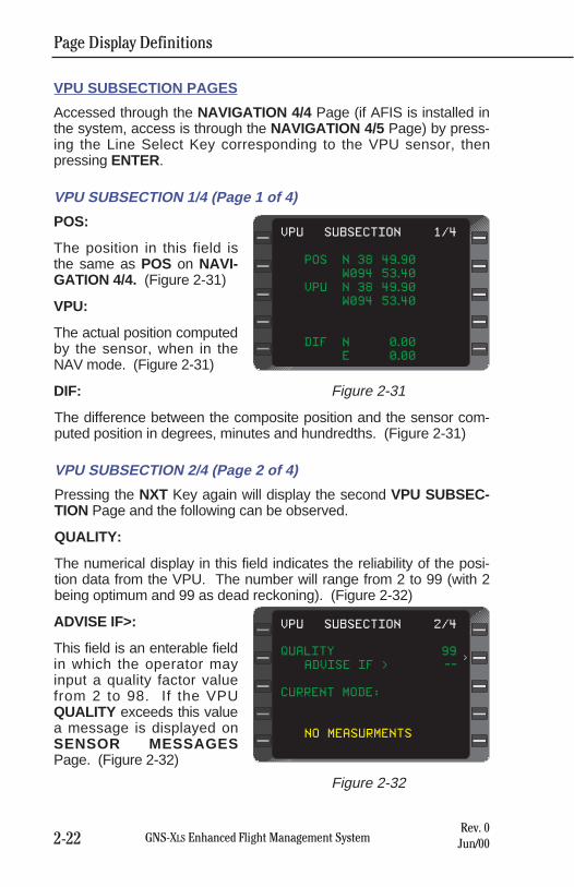
Page Display Definitions
2-22 GNS-XLS Enhanced Flight Management SystemRev. 0Jun/00
VPU SUBSECTION PAGES
Accessed through the NAVIGATION 4/4 Page (if AFIS is installed inthe system, access is through the NAVIGATION 4/5 Page) by press-ing the Line Select Key corresponding to the VPU sensor, thenpressing ENTER.
VPU SUBSECTION 1/4 (Page 1 of 4)
POS:
The position in this field isthe same as POS on NAVI-GATION 4/4. (Figure 2-31)
VPU:
The actual position computedby the sensor, when in theNAV mode. (Figure 2-31)
DIF:
The difference between the composite position and the sensor com-puted position in degrees, minutes and hundredths. (Figure 2-31)
VPU SUBSECTION 2/4 (Page 2 of 4)
Pressing the NXT Key again will display the second VPU SUBSEC-TION Page and the following can be observed.
QUALITY:
The numerical display in this field indicates the reliability of the posi-tion data from the VPU. The number will range from 2 to 99 (with 2being optimum and 99 as dead reckoning). (Figure 2-32)
ADVISE IF>:
This field is an enterable fieldin which the operator mayinput a quality factor valuefrom 2 to 98. If the VPUQUALITY exceeds this valuea message is displayed onSENSOR MESSAGESPage. (Figure 2-32)
POS N 38 49.90
W094 53.40
VPU N 38 49.90
W094 53.40
DIF N 0.00
E 0.00
VPU SUBSECTION 1/4
Figure 2-31
QUALITY 99
ADVISE IF > --
CURRENT MODE:
NO MEASURMENTS
VPU SUBSECTION 2/4
>
Figure 2-32
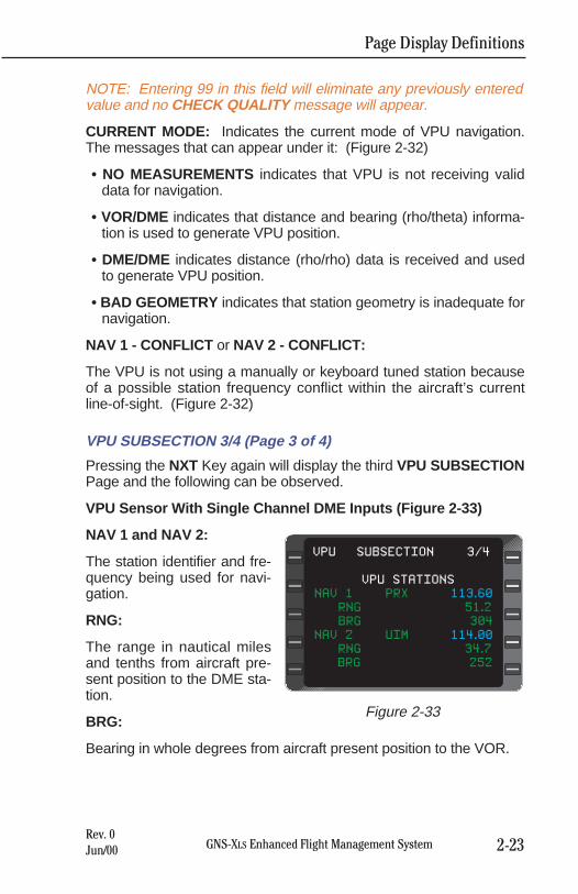
Page Display Definitions
2-23GNS-XLS Enhanced Flight Management SystemRev. 0Jun/00
NOTE: Entering 99 in this field will eliminate any previously enteredvalue and no CHECK QUALITY message will appear.
CURRENT MODE: Indicates the current mode of VPU navigation.The messages that can appear under it: (Figure 2-32)
• NO MEASUREMENTS indicates that VPU is not receiving validdata for navigation.
• VOR/DME indicates that distance and bearing (rho/theta) informa-tion is used to generate VPU position.
• DME/DME indicates distance (rho/rho) data is received and usedto generate VPU position.
• BAD GEOMETRY indicates that station geometry is inadequate fornavigation.
NAV 1 - CONFLICT or NAV 2 - CONFLICT:
The VPU is not using a manually or keyboard tuned station becauseof a possible station frequency conflict within the aircraft’s currentline-of-sight. (Figure 2-32)
VPU SUBSECTION 3/4 (Page 3 of 4)
Pressing the NXT Key again will display the third VPU SUBSECTIONPage and the following can be observed.
VPU Sensor With Single Channel DME Inputs (Figure 2-33)
NAV 1 and NAV 2:
The station identifier and fre-quency being used for navi-gation.
RNG:
The range in nautical milesand tenths from aircraft pre-sent position to the DME sta-tion.
BRG:
Bearing in whole degrees from aircraft present position to the VOR.
VPU STATIONS
NAV 1 PRX 113.60
RNG 51.2
BRG 304
NAV 2 UIM 114.00
RNG 34.7
BRG 252
VPU SUBSECTION 3/4
Figure 2-33
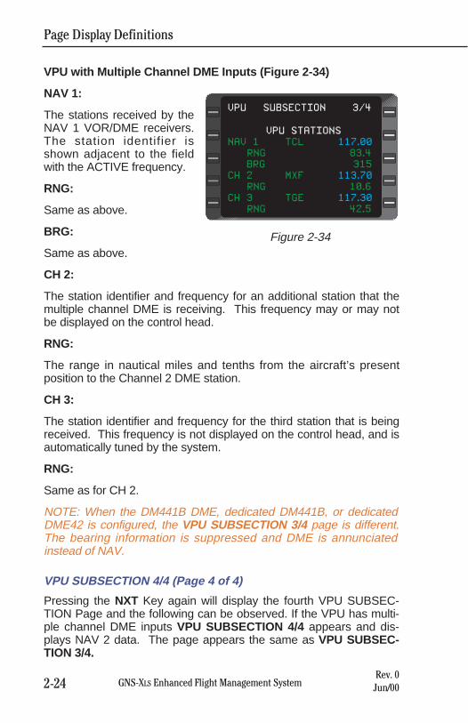
Page Display Definitions
2-24 GNS-XLS Enhanced Flight Management SystemRev. 0Jun/00
VPU with Multiple Channel DME Inputs (Figure 2-34)
NAV 1:
The stations received by theNAV 1 VOR/DME receivers.The station identifier isshown adjacent to the fieldwith the ACTIVE frequency.
RNG:
Same as above.
BRG:
Same as above.
CH 2:
The station identifier and frequency for an additional station that themultiple channel DME is receiving. This frequency may or may notbe displayed on the control head.
RNG:
The range in nautical miles and tenths from the aircraft’s presentposition to the Channel 2 DME station.
CH 3:
The station identifier and frequency for the third station that is beingreceived. This frequency is not displayed on the control head, and isautomatically tuned by the system.
RNG:
Same as for CH 2.
NOTE: When the DM441B DME, dedicated DM441B, or dedicatedDME42 is configured, the VPU SUBSECTION 3/4 page is different.The bearing information is suppressed and DME is annunciatedinstead of NAV.
VPU SUBSECTION 4/4 (Page 4 of 4)
Pressing the NXT Key again will display the fourth VPU SUBSEC-TION Page and the following can be observed. If the VPU has multi-ple channel DME inputs VPU SUBSECTION 4/4 appears and dis-plays NAV 2 data. The page appears the same as VPU SUBSEC-TION 3/4.
VPU STATIONS
NAV 1 TCL 117.00
RNG 83.4
BRG 315
CH 2 MXF 113.70
RNG 10.6
CH 3 TGE 117.30
RNG 42.5
VPU SUBSECTION 3/4
Figure 2-34
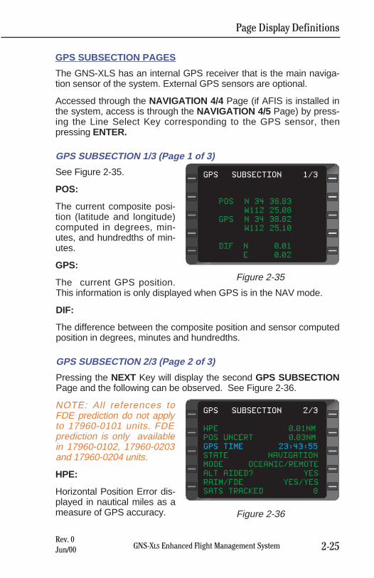
Page Display Definitions
2-25GNS-XLS Enhanced Flight Management SystemRev. 0Jun/00
GPS SUBSECTION PAGES
The GNS-XLS has an internal GPS receiver that is the main naviga-tion sensor of the system. External GPS sensors are optional.
Accessed through the NAVIGATION 4/4 Page (if AFIS is installed inthe system, access is through the NAVIGATION 4/5 Page) by press-ing the Line Select Key corresponding to the GPS sensor, thenpressing ENTER.
GPS SUBSECTION 1/3 (Page 1 of 3)
See Figure 2-35.
POS:
The current composite posi-tion (latitude and longitude)computed in degrees, min-utes, and hundredths of min-utes.
GPS:
The current GPS position.This information is only displayed when GPS is in the NAV mode.
DIF:
The difference between the composite position and sensor computedposition in degrees, minutes and hundredths.
GPS SUBSECTION 2/3 (Page 2 of 3)
Pressing the NEXT Key will display the second GPS SUBSECTIONPage and the following can be observed. See Figure 2-36.
NOTE: All references toFDE prediction do not applyto 17960-0101 units. FDEprediction is only availablein 17960-0102, 17960-0203and 17960-0204 units.
HPE:
Horizontal Position Error dis-played in nautical miles as ameasure of GPS accuracy.
POS N 34 38.83
W112 25.08
GPS N 34 38.82
W112 25.10
DIF N 0.01
E 0.02
GPS SUBSECTION 1/3
Figure 2-35
HPE 0.01NM
POS UNCERT 0.03NM
GPS TIME 23:43:55
STATE NAVIGATION
MODE OCEANIC/REMOTE
ALT AIDED? YES
RAIM/FDE YES/YES
SATS TRACKED 8
GPS SUBSECTION 2/3
Figure 2-36
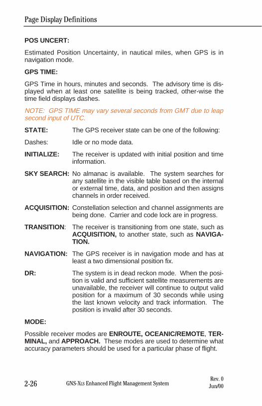
Page Display Definitions
2-26 GNS-XLS Enhanced Flight Management SystemRev. 0Jun/00
POS UNCERT:
Estimated Position Uncertainty, in nautical miles, when GPS is innavigation mode.
GPS TIME:
GPS Time in hours, minutes and seconds. The advisory time is dis-played when at least one satellite is being tracked, other-wise thetime field displays dashes.
NOTE: GPS TIME may vary several seconds from GMT due to leapsecond input of UTC.
STATE: The GPS receiver state can be one of the following:
Dashes: Idle or no mode data.
INITIALIZE: The receiver is updated with initial position and timeinformation.
SKY SEARCH: No almanac is available. The system searches forany satellite in the visible table based on the internalor external time, data, and position and then assignschannels in order received.
ACQUISITION: Constellation selection and channel assignments arebeing done. Carrier and code lock are in progress.
TRANSITION: The receiver is transitioning from one state, such asACQUISITION, to another state, such as NAVIGA-TION.
NAVIGATION: The GPS receiver is in navigation mode and has atleast a two dimensional position fix.
DR: The system is in dead reckon mode. When the posi-tion is valid and sufficient satellite measurements areunavailable, the receiver will continue to output validposition for a maximum of 30 seconds while usingthe last known velocity and track information. Theposition is invalid after 30 seconds.
MODE:
Possible receiver modes are ENROUTE, OCEANIC/REMOTE, TER-MINAL, and APPROACH. These modes are used to determine whataccuracy parameters should be used for a particular phase of flight.
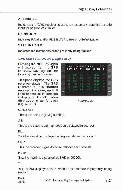
Page Display Definitions
2-27GNS-XLS Enhanced Flight Management SystemRev. 0Jun/00
ALT AIDED?:
Indicates the GPS receiver is using an externally supplied altitudeinput for position calculation.
RAIM/FDE?:
Indicates RAIM and/or FDE is AVAIL able or UNAVAIL able.
SATS TRACKED:
Indicates the number satellites presently being tracked.
GPS SUBSECTION 3/3 (Page 3 of 3)
Pressing the NXT Key againwill display the third GPSSUBSECTION Page and thefollowing can be observed.
This page displays the GPSreceiver status. The GPSreceiver is an 8 channelreceiver, therefore, up to 8lines of satellite informationis displayed. The informationdisplayed is as follows:(Figure 2-37)
GPS SAT:
This is the satellite (PRN) number.
AZ:
This is the satellite azimuth position displayed in degrees.
EL:
Satellite elevation displayed in degrees above the horizon.
SNR:
This the received signal-to-noise ratio for each satellite.
HLTH:
Satellite health is displayed as BAD or GOOD.
T:
YES or NO displayed as to whether this satellite is presently beingtracked.
SAT AZ EL SNR HLTH T
-- --- -- --- ---- -
14 304 71 44 GOOD Y
15 214 23 40 GOOD Y
22 124 47 44 GOOD Y
25 46 35 43 GOOD Y
29 304 40 40 GOOD Y
18 288 10 36 GOOD Y
-- --- -- -- ---- -
GPS SUBSECTION 3/3
Figure 2-37
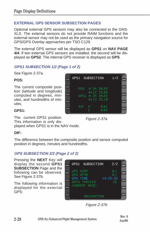
EXTERNAL GPS SENSOR SUBSECTION PAGES
Optional external GPS sensors may also be connected to the GNS-XLS. The external sensors do not provide RAIM functions and theexternal sensor may not be used as the primary navigation source forGPS/GPS Overlay approaches per TSO C129.
The external GPS sensor will be displayed as GPS1 on NAV PAGE4/4. If two external GPS sensors are installed, the second will be dis-played as GPS2. The internal GPS receiver is displayed as GPS.
GPS1 SUBSECTION 1/2 (Page 1 of 2)
See Figure 2-37a.
POS:
The current composite posi-tion (latitude and longitude)computed in degrees, min-utes, and hundredths of min-utes.
GPS1:
The current GPS1 position.This information is only dis-played when GPS1 is in the NAV mode.
DIF:
The difference between the composite position and sensor computedposition in degrees, minutes and hundredths.
GPS SUBSECTION 2/2 (Page 2 of 2)
Pressing the NEXT Key willdisplay the second GPS1SUBSECTION Page and thefollowing can be observed.See Figure 2-37b.
The following information isdisplayed for the external GPS:
Page Display Definitions
2-28 GNS-XLS Enhanced Flight Management SystemRev. 0Jun/00
POS N 34 38.83
W112 25.08
GPS1 N 34 38.82
W112 25.10
DIF N 0.01
E 0.02
GPS1 SUBSECTION 1/2
Figure 2-37a
GPS HDOP 0.1
GPS HFOM 0.1
GPS TIME 13:25:32
SATS TRACKED 10
CURRENT MODE:
NAVIGATION
GPS1 SUBSECTION 2/2
Figure 2-37b
GPS HDOP:
The GPS Horizontal Dilution of Precision. HDOP is a statistical mea-sure of GPS navigation quality. The lower the HDOP, the greater theprecision.
GPS HFOM:
Estimated horizontal GPS position accuracy, in nm, with 95% proba-bility.
GPS TIME:
GPS Time in hours, minutes and seconds.
SATS TRACKED:
The number of satellites presently tracked.
MODE:
The mode of the GPS receiver. Possible modes are:
SELF TEST Receiver is in self test.
INITIALIZATION Receiver initializing position information.
ACQUISITION Receiver acquiring satellite information.
NAVIGATION Receiver in normal navigation mode.
ALTITUDE/CLOCK AIDED Receiver using altitude for navigation.
DIFFERENTIAL Receiver applying differential corrections.
AIDED Receiver using other navigation information besidessatellite.
FAULT Receiver has detected a fault and is unusable.
LINK FAIL No communications between the FMS and externalGPS
Page Display Definitions
2-29GNS-XLS Enhanced Flight Management SystemRev. 0Jun/00
Page Display Definitions
2-30 GNS-XLS Enhanced Flight Management SystemRev. 0Jun/00
VERTICAL NAVIGATION SECTION (VNAV KEY)Upon pressing the VNAV Key the VNAV 1/3 Page will be displayedand the following can be observed.
VNAV PAGES
NOTE: AFIS flight plans do not support any altitudes, including air-port elevation. As a result no altitude constraints will be provided forSIDS, STARS or Approaches. If the airport, SIDs, STARS orApproaches are obtained from the database altitudes will be provid-ed.
In some programmed approaches, the altitude associated with theMAP waypoint is computed from the FAF through the MAP waypointto a point 50 feet above the runway threshold. MDA may be reachedprior to the MAP waypoint. The MDA must be observed if the run-way is not in sight.
VNAV 1/3 (Page 1 of 3)
VNAV MODE:
Mode required to fly to the vertical TO waypoint and Baro Altitude infeet. Can display one of the following:
• INVALID: Indicates VNAV function is invalid. In order to be setvalid the following must be met:
1. Air Data valid (baro altitude and altitude rate)
2. Valid lateral TO Waypoint
3. Valid vertical TO waypoint
4. NO SXTK programmed
5. Crosstrack (XTK) < 12.5NM
• INACTIVE: VNAV system is not activated because non-volatilememory was erased during software update or it was manually setinactive before shutdown. Using BACK Key with the cursor over theinactive field can display one of the following:
NOTE: When VNAV Mode is inactive, all external VNAV outputs aredisabled, including VERT DEV, EFIS altitude constraints at waypointsand VNAV WPT ALERT annunciation.
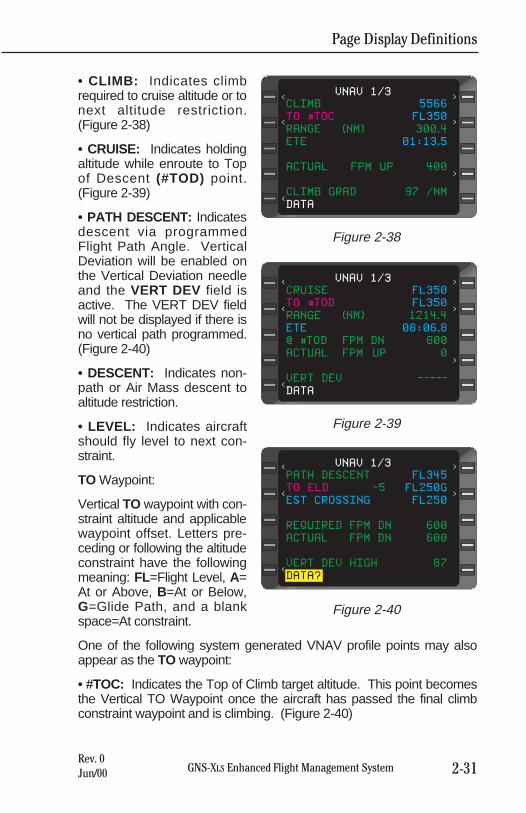
• CLIMB: Indicates climbrequired to cruise altitude or tonext altitude restriction.(Figure 2-38)
• CRUISE: Indicates holdingaltitude while enroute to Topof Descent (#TOD) point.(Figure 2-39)
• PATH DESCENT: Indicatesdescent via programmedFlight Path Angle. VerticalDeviation will be enabled onthe Vertical Deviation needleand the VERT DEV field isactive. The VERT DEV fieldwill not be displayed if there isno vertical path programmed.(Figure 2-40)
• DESCENT: Indicates non-path or Air Mass descent toaltitude restriction.
• LEVEL: Indicates aircraftshould fly level to next con-straint.
TO Waypoint:
Vertical TO waypoint with con-straint altitude and applicablewaypoint offset. Letters pre-ceding or following the altitudeconstraint have the followingmeaning: FL=Flight Level, A=At or Above, B=At or Below,G=Glide Path, and a blankspace=At constraint.
One of the following system generated VNAV profile points may alsoappear as the TO waypoint:
• #TOC: Indicates the Top of Climb target altitude. This point becomesthe Vertical TO Waypoint once the aircraft has passed the final climbconstraint waypoint and is climbing. (Figure 2-40)
Page Display Definitions
2-31GNS-XLS Enhanced Flight Management SystemRev. 0Jun/00
CLIMB 5566
TO #TOC FL350
RANGE (NM) 300.4
ETE 01:13.5
ACTUAL FPM UP 400
CLIMB GRAD 97 /NM
DATA
VNAV 1/3< <
< <
<
<
Figure 2-38
CRUISE FL350
TO #TOD FL350
RANGE (NM) 1214.4
ETE 08:06.8
@ #TOD FPM DN 800
ACTUAL FPM UP 0
VERT DEV -----
DATA
VNAV 1/3< <
< <
<
<
Figure 2-39
PATH DESCENT FL345
TO ELD -5 FL250G
EST CROSSING FL250
REQUIRED FPM DN 600
ACTUAL FPM DN 600
VERT DEV HIGH 87
DATA?
VNAV 1/3< <
< <
<
Figure 2-40
Page Display Definitions
2-32 GNS-XLS Enhanced Flight Management SystemRev. 0Jun/00
• #TOD: Indicates the Top of Descent target altitude where the aircraftshould begin its descent in order to arrive at the Descent ReferenceWaypoint at the required altitude. (Figure 2-39)
NOTE: If no Descent Reference Waypoint with crossing altitude is pro-grammed, the system will use the arrival airport elevation to fix the #TODas long as an airport is the last waypoint on the Active FPL.
EST CROSSING:
Altitude trajectory computed by the system to the Vertical TO waypointbased on current groundspeed and vertical speed (Figure 2-40). Thisfield will display RANGE (NM) in miles and tenths when the Vertical TOWaypoint is a #TOD or #TOC profile point. (Figure 2-39)
ETE:
The estimated time enroute in hours, minutes and tenths, from the aircraftpresent position to the Vertical TO Waypoint #TOC or #TOD. (Figure 2-39)
REQUIRED FPM:
Required vertical speed in feet per minute to make the altitude constraintbased on current ground speed. UP indicates a positive vertical speedand DN indicates a negative vertical speed (Figure 2-40). This field willdisplay @#TOD FPM DN when the Vertical TO Waypoint is the Top ofDescent and indicate the descent target vertical speed. (Figure 2-39)
ACTUAL FPM:
Actual vertical speed in feet per minute. UP indicates a positive verticalspeed and DN indicates a negative vertical speed. (Figures 2-39 and 2-40)
VERT DEV:
Vertical deviation of aircraft from this descent path in feet. HIGH indicatesaircraft is above the path (Figure 2-40); LOW indicates aircraft is belowpath. CLIMB GRAD xxx/NM is displayed during CLIMB mode to indicatecurrent aircraft climb performance in feet per nautical mile. (Figure 2-38)
NOTE: VERT DEV data field is dashes if the ETE to descent path inter-cept is greater than one minute. This line will be blank if no FPA is pro-grammed at descent reference waypoint. In this case #TOD will be deter-mined using the default FPA from the VNAV DATA Page. However theFPA must still be entered for the system to provide a path.
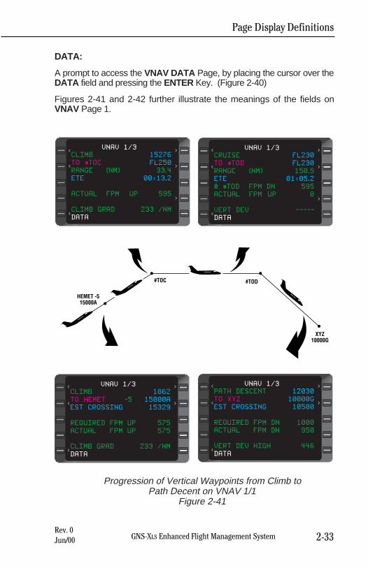
Page Display Definitions
2-33GNS-XLS Enhanced Flight Management SystemRev. 0Jun/00
DATA:
A prompt to access the VNAV DATA Page, by placing the cursor over theDATA field and pressing the ENTER Key. (Figure 2-40)
Figures 2-41 and 2-42 further illustrate the meanings of the fields onVNAV Page 1.
CLIMB 15276
TO #TOC FL250
RANGE (NM) 33.4
ETE 00:13.2
ACTUAL FPM UP 595
CLIMB GRAD 233 /NM
DATA
VNAV 1/3< <
< <
<
<
CRUISE FL230
TO #TOD FL230
RANGE (NM) 150.5
ETE 01:05.2
@ #TOD FPM DN 595
ACTUAL FPM UP 0
VERT DEV -----
DATA
VNAV 1/3< <
< <
<
<
CLIMB 1862
TO HEMET -5 15000A
EST CROSSING 15329
REQUIRED FPM UP 575
ACTUAL FPM UP 575
CLIMB GRAD 233 /NM
DATA
VNAV 1/3< <
< <
<
PATH DESCENT 12030
TO XYZ 10000G
EST CROSSING 10500
REQUIRED FPM DN 1000
ACTUAL FPM DN 950
VERT DEV HIGH 446
DATA
VNAV 1/3< <
< <
<
Progression of Vertical Waypoints from Climb toPath Decent on VNAV 1/1
Figure 2-41
XYZ10000G
#TOD#TOC
HEMET -515000A
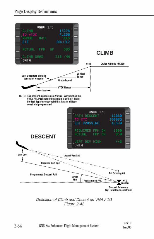
Page Display Definitions
2-34 GNS-XLS Enhanced Flight Management SystemRev. 0Jun/00
Last Departure altitudeconstraint waypoint
Groundspeed
Vertical Speed
#TOC Cruise Altitude =FL250
#TOC Range1nm
Top of Climb appears as a Vertical Waypoint on the VNAV FPL Page when the aircraft is within 1 NM of the last departure waypoint that has an altitude constraint programmed
NOTE:
CLIMB 15276
TO #TOC FL250
RANGE (NM) 33.5
ETE 00:13.2
ACTUAL FPM UP 595
CLIMB GRAD 233 /NM
DATA
VNAV 1/3< <
< <
<
Vert Dev
Required Vert Spd
Actual Vert Spd
Programmed Descent PathDirect
FPA Programmed FPA
Est Crossing Alt
Descent Reference Wpt (at altitude constraint)
XYZ10000G
PATH DESCENT 12030
TO XYZ 10000G
EST CROSSING 10500
REQUIRED FPM DN 1000
ACTUAL FPM DN 950
VERT DEV HIGH 446
DATA
VNAV 1/3< <
< <
<
CLIMB
DESCENT
Definition of Climb and Decent on VNAV 1/1Figure 2-42
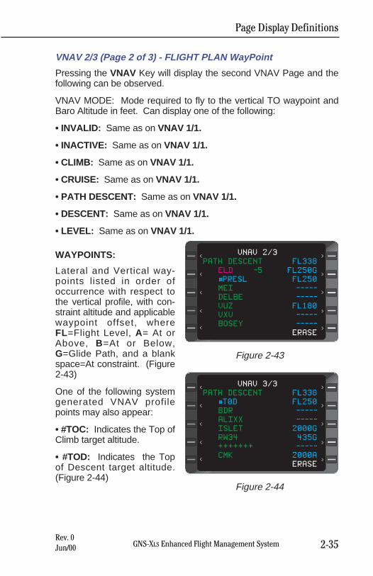
Page Display Definitions
2-35GNS-XLS Enhanced Flight Management SystemRev. 0Jun/00
VNAV 2/3 (Page 2 of 3) - FLIGHT PLAN WayPoint
Pressing the VNAV Key will display the second VNAV Page and thefollowing can be observed.
VNAV MODE: Mode required to fly to the vertical TO waypoint andBaro Altitude in feet. Can display one of the following:
• INVALID: Same as on VNAV 1/1.
• INACTIVE: Same as on VNAV 1/1.
• CLIMB: Same as on VNAV 1/1.
• CRUISE: Same as on VNAV 1/1.
• PATH DESCENT: Same as on VNAV 1/1.
• DESCENT: Same as on VNAV 1/1.
• LEVEL: Same as on VNAV 1/1.
WAYPOINTS:
Lateral and Vertical way-points listed in order ofoccurrence with respect tothe vertical profile, with con-straint altitude and applicablewaypoint offset, whereFL=Flight Level, A= At orAbove, B=At or Below,G=Glide Path, and a blankspace=At constraint. (Figure2-43)
One of the following systemgenerated VNAV profilepoints may also appear:
• #TOC: Indicates the Top ofClimb target altitude.
• #TOD: Indicates the Topof Descent target altitude.(Figure 2-44)
PATH DESCENT FL338
ELD -5 FL250G
#PRESL FL250
MEI -----
DELBE -----
VUZ FL180
VXV -----
BOSEY -----
ERASE
VNAV 2/3< <
< <
<
<
<
<
<
<
Figure 2-43
PATH DESCENT FL338
#T0D FL250
BDR -----
ALIXX -----
ISLET 2000G
RW34 435G
+++++++ -----
CMK 2000A
ERASE
VNAV 3/3< <
< <
<
<
<
<
<
<
Figure 2-44
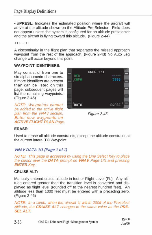
Page Display Definitions
2-36 GNS-XLS Enhanced Flight Management SystemRev. 0Jun/00
• #PRESL: Indicates the estimated position where the aircraft willarrive at the altitude shown on the Altitude Pre-Selector. Field doesnot appear unless the system is configured for an altitude preselectorand the aircraft is flying toward this altitude. (Figure 2-44)
++++++ :
A discontinuity in the flight plan that separates the missed approachwaypoint from the rest of the approach. (Figure 2-43) No Auto Legchange will occur beyond this point.
WAYPOINT IDENTIFIERS:
May consist of from one tosix alphanumeric characters.If more identifiers are presentthan can be listed on thispage, subsequent pages willlist the remaining waypoints.(Figure 2-45)
NOTE: Waypoints cannotbe added to the active flightplan from the VNAV section.Enter new waypoints onACTIVE FLIGHT PLAN Page.
ERASE:
Used to erase all altitude constraints, except the altitude constraint atthe current lateral TO Waypoint.
VNAV DATA 1/1 (Page 1 of 1)
NOTE: This page is accessed by using the Line Select Key to placethe cursor over the DATA prompt on VNAV Page 1/X and pressingENTER Key.
CRUISE ALT:
Manually entered cruise altitude in feet or Flight Level (FL). Any alti-tude entered greater than the transition level is converted and dis-played as flight level (rounded off to the nearest hundred feet). Analtitude less than 1000 feet must be entered with a preceding zero.(Figure 2-46)
NOTE: In a climb, when the aircraft is within 200ft of the PreselectAltitude, the CRUISE ALT changes to the same value as the PRE-SEL ALT .
DEN -----
KAPA 5883
DATA ERASE
VNAV 1/X
<
< <
Figure 2-45
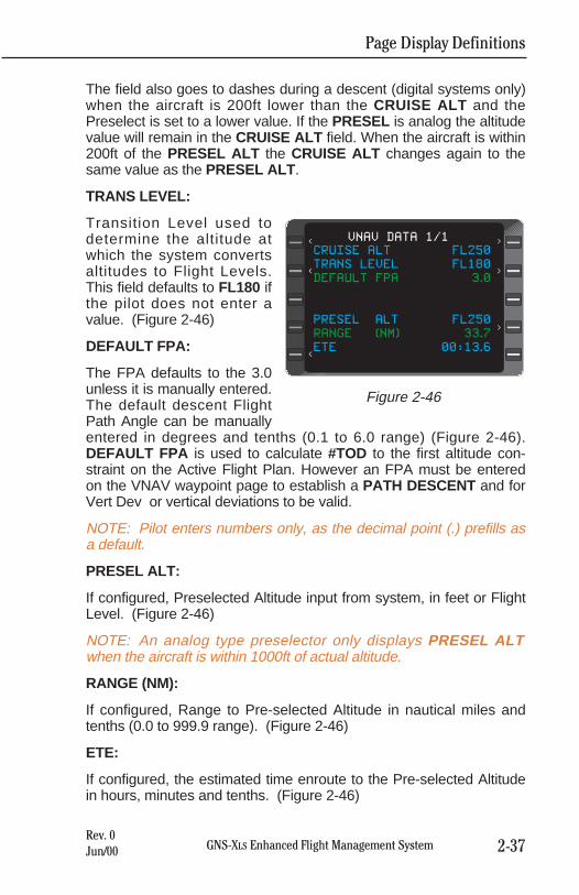
The field also goes to dashes during a descent (digital systems only)when the aircraft is 200ft lower than the CRUISE ALT and thePreselect is set to a lower value. If the PRESEL is analog the altitudevalue will remain in the CRUISE ALT field. When the aircraft is within200ft of the PRESEL ALT the CRUISE ALT changes again to thesame value as the PRESEL ALT .
TRANS LEVEL:
Transition Level used todetermine the altitude atwhich the system convertsaltitudes to Flight Levels.This field defaults to FL180 ifthe pilot does not enter avalue. (Figure 2-46)
DEFAULT FPA:
The FPA defaults to the 3.0unless it is manually entered.The default descent FlightPath Angle can be manuallyentered in degrees and tenths (0.1 to 6.0 range) (Figure 2-46).DEFAULT FPA is used to calculate #TOD to the first altitude con-straint on the Active Flight Plan. However an FPA must be enteredon the VNAV waypoint page to establish a PATH DESCENT and forVert Dev or vertical deviations to be valid.
NOTE: Pilot enters numbers only, as the decimal point (.) prefills asa default.
PRESEL ALT:
If configured, Preselected Altitude input from system, in feet or FlightLevel. (Figure 2-46)
NOTE: An analog type preselector only displays PRESEL ALTwhen the aircraft is within 1000ft of actual altitude.
RANGE (NM):
If configured, Range to Pre-selected Altitude in nautical miles andtenths (0.0 to 999.9 range). (Figure 2-46)
ETE:
If configured, the estimated time enroute to the Pre-selected Altitudein hours, minutes and tenths. (Figure 2-46)
Page Display Definitions
2-37GNS-XLS Enhanced Flight Management SystemRev. 0Jun/00
CRUISE ALT FL250
TRANS LEVEL FL180
DEFAULT FPA 3.0
PRESEL ALT FL250
RANGE (NM) 33.7
ETE 00:13.6
VNAV DATA 1/1< <
< <
<
<
Figure 2-46
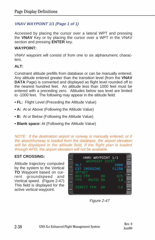
Page Display Definitions
2-38 GNS-XLS Enhanced Flight Management SystemRev. 0Jun/00
VNAV WAYPOINT 1/1 (Page 1 of 1)
Accessed by placing the cursor over a lateral WPT and pressingthe VNAV Key or by placing the cursor over a WPT in the VNAVsection and pressing ENTER key.
WAYPOINT:
VNAV waypoint will consist of from one to six alphanumeric charac-ters.
ALT:
Constraint altitude prefills from database or can be manually entered.Any altitude entered greater than the transition level (from the VNAVDATA Page) is converted and displayed as flight level rounded off tothe nearest hundred feet. An altitude less than 1000 feet must beentered with a preceding zero. Altitudes below sea level are limitedto -1000 feet. The following may appear in the altitude field:
• FL: Flight Level (Preceding the Altitude Value)
• A: At or Above (Following the Altitude Value)
• B: At or Below (Following the Altitude Value)
• Blank space: At (Following the Altitude Value)
NOTE: If the destination airport or runway is manually entered, or ifthe airport/runway is loaded from the database, the airport elevationwill be displayed in the altitude field. If the flight plan is loadedthrough AFIS, the airport elevation will not be available.
EST CROSSING:
Altitude trajectory computedby the system to the VerticalTO Waypoint based on cur-rent groundspeed andVertical speed. (Figure 2-47)This field is displayed for theactive vertical waypoint.
WAYPOINT ISTET
ALT 2000
EST CROSSING FL250
OFFSET ---
REQ FPM DN 825
FPA (AUTO) DN 3.0
DIRECT FPA DN 2.8
VNAV WAYPOINT 1/1
<
<
<
Figure 2-47
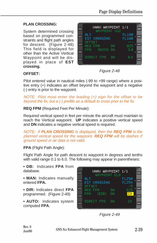
Page Display Definitions
2-39GNS-XLS Enhanced Flight Management SystemRev. 0Jun/00
PLAN CROSSING:
System determined crossingbased on programmed con-straints and flight path anglesfor descent. (Figure 2-48)This field is displayed forother than the Active VerticalWaypoint and will be dis-played in place of ESTcrossing.
OFFSET:
Pilot entered value in nautical miles (-99 to +99 range) where a posi-tive entry (+) indicates an offset beyond the waypoint and a negative(-) entry is prior to the waypoint.
NOTE: Pilot must enter the leading (+) sign for the offset to bebeyond the fix, but a (-) prefills as a default to cross prior to the fix.
REQ FPM (Required Feet Per Minute):
Required vertical speed in feet per minute the aircraft must maintain toreach the Vertical waypoint. UP indicates a positive vertical speedand DN indicates a negative vertical speed is required.
NOTE: If PLAN CROSSING is displayed, then the REQ FPM is theplanned vertical speed for the waypoint. REQ FPM will be dashes ifground speed or air data is not valid.
FPA (Flight Path Angle):
Flight Path Angle for path descent to waypoint in degrees and tenthswith valid range 0.1 to 6.0. The following may appear in parentheses:
• DB: Indicates FPA fromdatabase.
• MAN: Indicates manuallyentered FPA.
• DIR: Indicates direct FPAprogrammed. (Figure 2-49)
• AUTO: Indicates systemcomputed FPA.
WAYPOINT VUZ
ALT FL180
EST CROSSING FL180
OFFSET ---
REQ FPM DN 825
FPA (AUTO) DN 3.0
DIRECT FPA DN 0.4
VNAV WAYPOINT 1/1
<
<
<
Figure 2-48
WAYPOINT ELD
ALT FL250
EST CROSSING FL254
OFFSET -5
REQ FPM DN 625
FPA (DIR) DN 2.3
DIRECT FPA DN 2.3
VNAV WAYPOINT 1/1
<
<
<
Figure 2-49
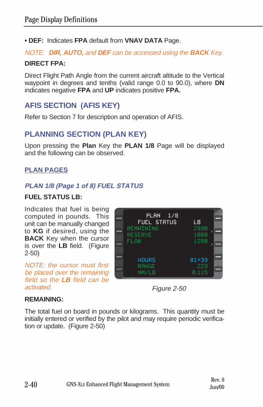
Page Display Definitions
2-40 GNS-XLS Enhanced Flight Management SystemRev. 0Jun/00
• DEF: Indicates FPA default from VNAV DATA Page.
NOTE: DIR, AUTO, and DEF can be accessed using the BACK Key.
DIRECT FPA:
Direct Flight Path Angle from the current aircraft altitude to the Verticalwaypoint in degrees and tenths (valid range 0.0 to 90.0), where DNindicates negative FPA and UP indicates positive FPA.
AFIS SECTION (AFIS KEY)Refer to Section 7 for description and operation of AFIS.
PLANNING SECTION (PLAN KEY)Upon pressing the Plan Key the PLAN 1/8 Page will be displayedand the following can be observed.
PLAN PAGES
PLAN 1/8 (Page 1 of 8) FUEL STATUS
FUEL STATUS LB:
Indicates that fuel is beingcomputed in pounds. Thisunit can be manually changedto KG if desired, using theBACK Key when the cursoris over the LB field. (Figure2-50)
NOTE: the cursor must firstbe placed over the remainingfield so the LB field can beactivated.
REMAINING:
The total fuel on board in pounds or kilograms. This quantity must beinitially entered or verified by the pilot and may require periodic verifica-tion or update. (Figure 2-50)
PLAN 1/8
FUEL STATUS LB
REMAINING 2990
RESERVE 1000
FLOW 1200
HOURS 01+39
RANGE 229
NM/LB 0.115
>
>
Figure 2-50
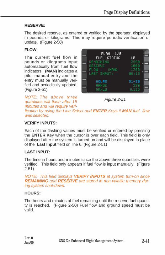
Page Display Definitions
2-41GNS-XLS Enhanced Flight Management SystemRev. 0Jun/00
RESERVE:
The desired reserve, as entered or verified by the operator, displayedin pounds or kilograms. This may require periodic verification orupdate. (Figure 2-50)
FLOW:
The current fuel flow inpounds or kilograms inputautomatically from fuel flowindicators. (MAN) indicates apilot manual entry and theentry must be manually veri-fied and periodically updated.(Figure 2-51)
NOTE: The above threequantities will flash after 15minutes and will require veri-fication by using the Line Select and ENTER Keys if MAN fuel flowwas selected.
VERIFY INPUTS:
Each of the flashing values must be verified or entered by pressingthe ENTER Key when the cursor is over each field. This field is onlydisplayed after the system is turned on and will be displayed in placeof the Last Input field on line 6. (Figure 2-51)
LAST INPUT:
The time in hours and minutes since the above three quantities wereverified. This field only appears if fuel flow is input manually. (Figure2-51)
NOTE: This field displays VERIFY INPUTS at system turn-on sinceREMAINING and RESERVE are stored in non-volatile memory dur-ing system shut-down.
HOURS:
The hours and minutes of fuel remaining until the reserve fuel quanti-ty is reached. (Figure 2-50) Fuel flow and ground speed must bevalid.
PLAN 1/8
FUEL STATUS LB
REMAINING 2990
RESERVE 1000
FLOW (MAN) 1200
LAST INPUT: 00:15
HOURS 01+39
RANGE 229
NM/LB 0.115
>
>
Figure 2-51
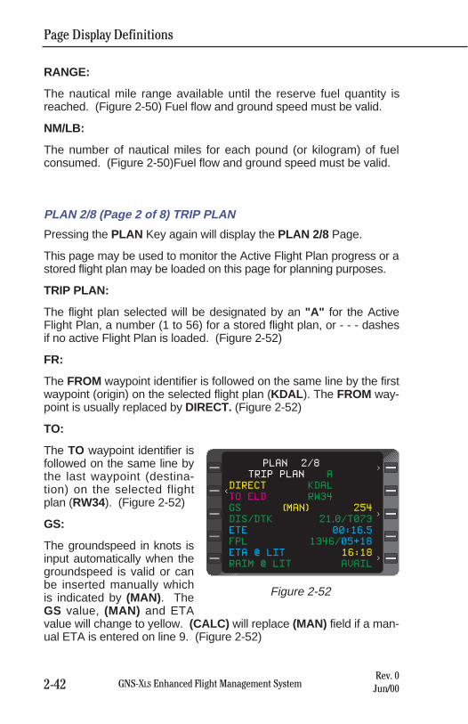
RANGE:
The nautical mile range available until the reserve fuel quantity isreached. (Figure 2-50) Fuel flow and ground speed must be valid.
NM/LB:
The number of nautical miles for each pound (or kilogram) of fuelconsumed. (Figure 2-50)Fuel flow and ground speed must be valid.
PLAN 2/8 (Page 2 of 8) TRIP PLAN
Pressing the PLAN Key again will display the PLAN 2/8 Page.
This page may be used to monitor the Active Flight Plan progress or astored flight plan may be loaded on this page for planning purposes.
TRIP PLAN:
The flight plan selected will be designated by an "A" for the ActiveFlight Plan, a number (1 to 56) for a stored flight plan, or - - - dashesif no active Flight Plan is loaded. (Figure 2-52)
FR:
The FROM waypoint identifier is followed on the same line by the firstwaypoint (origin) on the selected flight plan (KDAL ). The FROM way-point is usually replaced by DIRECT. (Figure 2-52)
TO:
The TO waypoint identifier isfollowed on the same line bythe last waypoint (destina-tion) on the selected flightplan (RW34). (Figure 2-52)
GS:
The groundspeed in knots isinput automatically when thegroundspeed is valid or canbe inserted manually whichis indicated by (MAN). TheGS value, (MAN) and ETAvalue will change to yellow. (CALC) will replace (MAN) field if a man-ual ETA is entered on line 9. (Figure 2-52)
Page Display Definitions
2-42 GNS-XLS Enhanced Flight Management SystemRev. 0Jun/00
TRIP PLAN A
DIRECT KDAL
TO ELD RW34
GS (MAN) 254
DIS/DTK 21.0/T073
ETE 00:16.5
FPL 1346/05+18
ETA @ LIT 16:18
RAIM @ LIT AVAIL
PLAN 2/8
<
<
<
<
Figure 2-52
Page Display Definitions
2-43GNS-XLS Enhanced Flight Management SystemRev. 0Jun/00
DIS/DTK:
The distance in nautical miles and tenths between either the FROMand TO waypoints or between the aircraft's present position and theTO waypoint. The desired track is the Great Circle course betweenthe FROM and TO waypoints. The DTK will have a T adjacent to it ifa true heading input is received or if the FROM waypoint is north N70° or south S 60° latitude. (Figure 2-52)
ETE:
The estimated time enroute in hours, minutes and tenths of minutesbetween the aircraft's present position and the TO waypoint or theFROM and TO waypoints based on the GS value. (Figure 2-52)
FPL:
The total active or stored flight plan distance and time remaining via theFlight Planned route from the FROM waypoint, (or the aircraft's presentposition when a Direct To leg is displayed), to the last waypoint on theselected flight plan that precedes a "fence". Distance is displayed inwhole miles and time is in hours and minutes. (Figure 2-52)
ETA @:
Estimated time of arrival at the destination, or last waypoint on theActive Flight Plan that precedes a "fence", appears when a DIRECTTO leg is displayed. (Figure 2-52)
NOTE: The ETA value field will turn yellow if a ground speed isentered manually, indicating that the ETA is calculated based on themanual ground speed value. The GS field will turn yellow and(CALC) will be displayed if a manual ETA value is entered.
RAIM @:
Receiver Autonomous Integrity Monitoring at the last flight plan way-point will display AVAIL (available) or NOT AVAIL (not available) atthe ETA. If a manual ground speed or ETA has been entered,STANDBY will be displayed momentarily while the system calculatesRAIM availability. If GPS is not functioning, NO NAV will be dis-played.
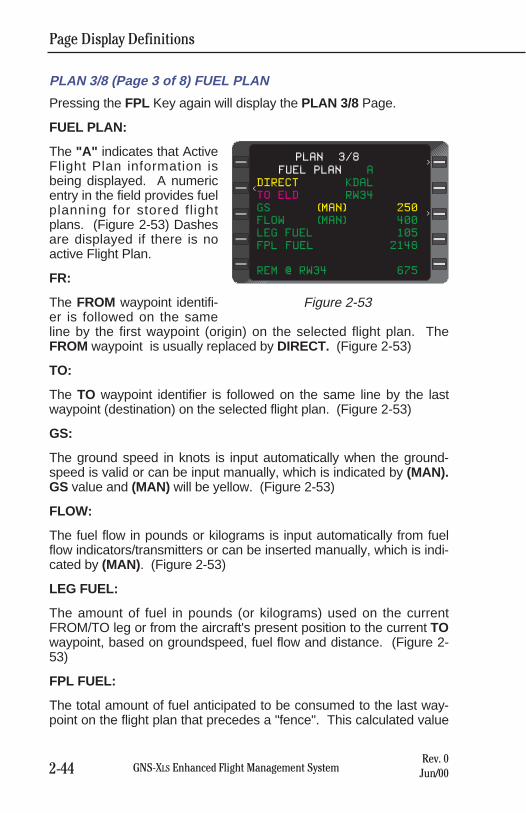
PLAN 3/8 (Page 3 of 8) FUEL PLAN
Pressing the FPL Key again will display the PLAN 3/8 Page.
FUEL PLAN:
The "A" indicates that ActiveFlight Plan information isbeing displayed. A numericentry in the field provides fuelplanning for stored flightplans. (Figure 2-53) Dashesare displayed if there is noactive Flight Plan.
FR:
The FROM waypoint identifi-er is followed on the sameline by the first waypoint (origin) on the selected flight plan. TheFROM waypoint is usually replaced by DIRECT. (Figure 2-53)
TO:
The TO waypoint identifier is followed on the same line by the lastwaypoint (destination) on the selected flight plan. (Figure 2-53)
GS:
The ground speed in knots is input automatically when the ground-speed is valid or can be input manually, which is indicated by (MAN).GS value and (MAN) will be yellow. (Figure 2-53)
FLOW:
The fuel flow in pounds or kilograms is input automatically from fuelflow indicators/transmitters or can be inserted manually, which is indi-cated by (MAN). (Figure 2-53)
LEG FUEL:
The amount of fuel in pounds (or kilograms) used on the currentFROM/TO leg or from the aircraft's present position to the current TOwaypoint, based on groundspeed, fuel flow and distance. (Figure 2-53)
FPL FUEL:
The total amount of fuel anticipated to be consumed to the last way-point on the flight plan that precedes a "fence". This calculated value
Page Display Definitions
2-44 GNS-XLS Enhanced Flight Management SystemRev. 0Jun/00
FUEL PLAN A
DIRECT KDAL
TO ELD RW34
GS (MAN) 250
FLOW (MAN) 400
LEG FUEL 105
FPL FUEL 2148
REM @ RW34 675
PLAN 3/8
<
<
<
Figure 2-53
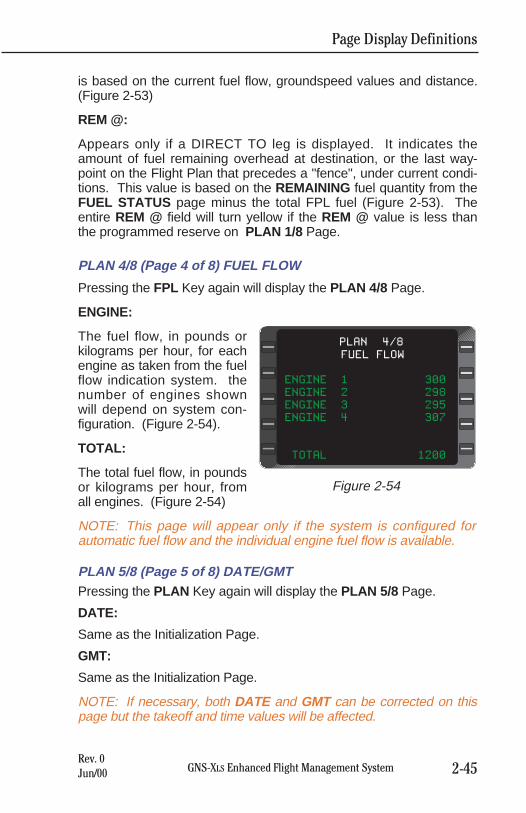
is based on the current fuel flow, groundspeed values and distance.(Figure 2-53)
REM @:
Appears only if a DIRECT TO leg is displayed. It indicates theamount of fuel remaining overhead at destination, or the last way-point on the Flight Plan that precedes a "fence", under current condi-tions. This value is based on the REMAINING fuel quantity from theFUEL STATUS page minus the total FPL fuel (Figure 2-53). Theentire REM @ field will turn yellow if the REM @ value is less thanthe programmed reserve on PLAN 1/8 Page.
PLAN 4/8 (Page 4 of 8) FUEL FLOW
Pressing the FPL Key again will display the PLAN 4/8 Page.
ENGINE:
The fuel flow, in pounds orkilograms per hour, for eachengine as taken from the fuelflow indication system. thenumber of engines shownwill depend on system con-figuration. (Figure 2-54).
TOTAL:
The total fuel flow, in poundsor kilograms per hour, fromall engines. (Figure 2-54)
NOTE: This page will appear only if the system is configured forautomatic fuel flow and the individual engine fuel flow is available.
PLAN 5/8 (Page 5 of 8) DATE/GMTPressing the PLAN Key again will display the PLAN 5/8 Page.
DATE:
Same as the Initialization Page.
GMT:
Same as the Initialization Page.
NOTE: If necessary, both DATE and GMT can be corrected on thispage but the takeoff and time values will be affected.
Page Display Definitions
2-45GNS-XLS Enhanced Flight Management SystemRev. 0Jun/00
FUEL FLOW
ENGINE 1 300
ENGINE 2 298
ENGINE 3 295
ENGINE 4 307
TOTAL 1200
PLAN 4/8
Figure 2-54
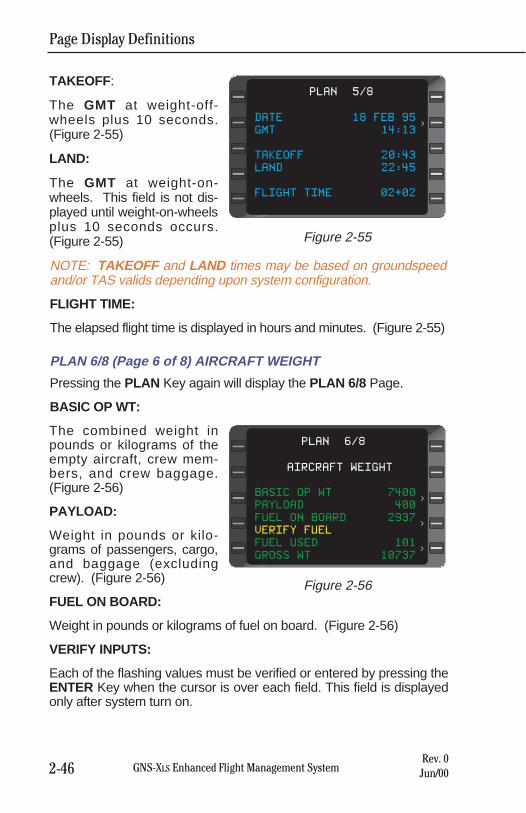
Page Display Definitions
2-46 GNS-XLS Enhanced Flight Management SystemRev. 0Jun/00
TAKEOFF :
The GMT at weight-off-wheels plus 10 seconds.(Figure 2-55)
LAND:
The GMT at weight-on-wheels. This field is not dis-played until weight-on-wheelsplus 10 seconds occurs.(Figure 2-55)
NOTE: TAKEOFF and LAND times may be based on groundspeedand/or TAS valids depending upon system configuration.
FLIGHT TIME:
The elapsed flight time is displayed in hours and minutes. (Figure 2-55)
PLAN 6/8 (Page 6 of 8) AIRCRAFT WEIGHT
Pressing the PLAN Key again will display the PLAN 6/8 Page.
BASIC OP WT:
The combined weight inpounds or kilograms of theempty aircraft, crew mem-bers, and crew baggage.(Figure 2-56)
PAYLOAD:
Weight in pounds or kilo-grams of passengers, cargo,and baggage (excludingcrew). (Figure 2-56)
FUEL ON BOARD:
Weight in pounds or kilograms of fuel on board. (Figure 2-56)
VERIFY INPUTS:
Each of the flashing values must be verified or entered by pressing theENTER Key when the cursor is over each field. This field is displayedonly after system turn on.
DATE 18 FEB 95
GMT 14:13
TAKEOFF 20:43
LAND 22:45
FLIGHT TIME 02+02
PLAN 5/8
<
Figure 2-55
AIRCRAFT WEIGHT
BASIC OP WT 7400
PAYLOAD 400
FUEL ON BOARD 2937
VERIFY FUEL
FUEL USED 101
GROSS WT 10737
PLAN 6/8
<
<
<
Figure 2-56
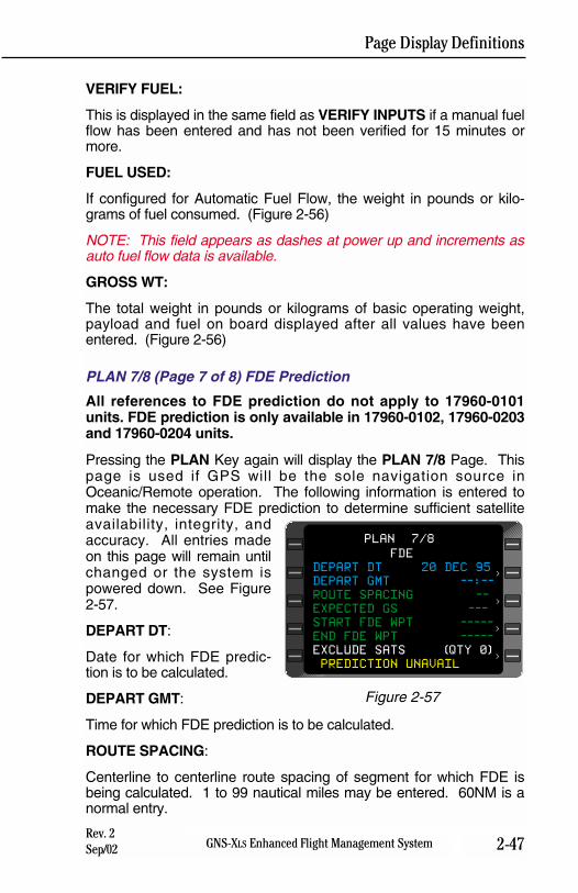
VERIFY FUEL:
This is displayed in the same field as VERIFY INPUTS if a manual fuelflow has been entered and has not been verified for 15 minutes ormore.
FUEL USED:
If configured for Automatic Fuel Flow, the weight in pounds or kilo-grams of fuel consumed. (Figure 2-56)
NOTE: This field appears as dashes at power up and increments asauto fuel flow data is available.
GROSS WT:
The total weight in pounds or kilograms of basic operating weight,payload and fuel on board displayed after all values have beenentered. (Figure 2-56)
PLAN 7/8 (Page 7 of 8) FDE Prediction
All references to FDE prediction do not apply to 17960-0101units. FDE prediction is only available in 17960-0102, 17960-0203and 17960-0204 units.
Pressing the PLAN Key again will display the PLAN 7/8 Page. Thispage is used if GPS will be the sole navigation source inOceanic/Remote operation. The following information is entered tomake the necessary FDE prediction to determine sufficient satelliteavailability, integrity, andaccuracy. All entries madeon this page will remain untilchanged or the system ispowered down. See Figure2-57.
DEPART DT:
Date for which FDE predic-tion is to be calculated.
DEPART GMT:
Time for which FDE prediction is to be calculated.
ROUTE SPACING:
Centerline to centerline route spacing of segment for which FDE isbeing calculated. 1 to 99 nautical miles may be entered. 60NM is anormal entry.
Page Display Definitions
2-47GNS-XLS Enhanced Flight Management SystemRev. 2Sep/02
FDE
DEPART DT 20 DEC 95
DEPART GMT --:--
ROUTE SPACING --
EXPECTED GS ---
START FDE WPT -----
END FDE WPT -----
EXCLUDE SATS (QTY 0)
PREDICTION UNAVAIL
PLAN 7/8
<
<
<
<
Figure 2-57
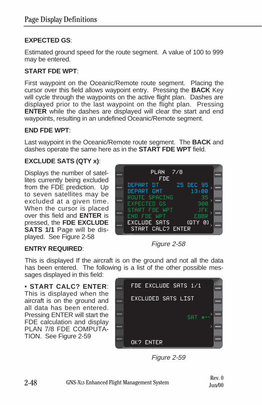
Page Display Definitions
2-48 GNS-XLS Enhanced Flight Management SystemRev. 0Jun/00
EXPECTED GS:
Estimated ground speed for the route segment. A value of 100 to 999may be entered.
START FDE WPT:
First waypoint on the Oceanic/Remote route segment. Placing thecursor over this field allows waypoint entry. Pressing the BACK Keywill cycle through the waypoints on the active flight plan. Dashes aredisplayed prior to the last waypoint on the flight plan. PressingENTER while the dashes are displayed will clear the start and endwaypoints, resulting in an undefined Oceanic/Remote segment.
END FDE WPT:
Last waypoint in the Oceanic/Remote route segment. The BACK anddashes operate the same here as in the START FDE WPT field.
EXCLUDE SATS (QTY x) :
Displays the number of satel-lites currently being excludedfrom the FDE prediction. Upto seven satellites may beexcluded at a given time.When the cursor is placedover this field and ENTER ispressed, the FDE EXCLUDESATS 1/1 Page will be dis-played. See Figure 2-58
ENTRY REQUIRED:
This is displayed If the aircraft is on the ground and not all the datahas been entered. The following is a list of the other possible mes-sages displayed in this field:
• START CALC? ENTER :This is displayed when theaircraft is on the ground andall data has been entered.Pressing ENTER will start theFDE calculation and displayPLAN 7/8 FDE COMPUTA-TION. See Figure 2-59
FDE
DEPART DT 25 DEC 95
DEPART GMT 13:00
ROUTE SPACING 35
EXPECTED GS 300
START FDE WPT JFK
END FDE WPT EBBR
EXCLUDE SATS (QTY 0)
START CALC? ENTER
PLAN 7/8
<
<
<
<
Figure 2-58
EXCLUDED SATS LIST
SAT #--
OK? ENTER
FDE EXCLUDE SATS 1/1
<
<
Figure 2-59
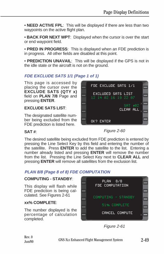
Page Display Definitions
2-49GNS-XLS Enhanced Flight Management SystemRev. 0Jun/00
• NEED ACTIVE FPL : This will be displayed if there are less than twowaypoints on the active flight plan.
• BACK FOR NEXT WPT : Displayed when the cursor is over the startor end waypoint field.
• PRED IN PROGRESS: This is displayed when an FDE prediction isin progress. All other fields are disabled at this point.
• PREDICTION UNAVAIL : This will be displayed if the GPS is not inthe idle state or the aircraft is not on the ground.
FDE EXCLUDE SATS 1/1 (Page 1 of 1)
This page is accessed byplacing the cursor over theEXCLUDE SATS (QTY x)field on PLAN 7/8 Page andpressing ENTER.
EXCLUDE SATS LIST :
The designated satellite num-ber being excluded from theFDE prediction is listed here.
SAT #:
The desired satellite being excluded from FDE prediction is entered bypressing the Line Select Key by this field and entering the number ofthe satellite. Press ENTER to add the satellite to the list. Entering anumber already listed and pressing ENTER will remove the numberfrom the list. Pressing the Line Select Key next to CLEAR ALL andpressing ENTER will remove all satellites from the exclusion list.
PLAN 8/8 (Page 8 of 8) FDE COMPUTATION
COMPUTING - STANDBY :
This display will flash whileFDE prediction is being cal-culated. See Figures 2-61
xx% COMPLETE :
The number displayed is thepercentage of calculationcompleted.
EXCLUDED SATS LIST
12 14 02 16 19 22 07
SAT #02
CLEAR ALL
OK? ENTER
FDE EXCLUDE SATS 1/1
<
<
Figure 2-60
FDE COMPUTATION
COMPUTING - STANDBY
51% COMPLETE
CANCEL COMPUTE
PLAN 8/8
<
Figure 2-61
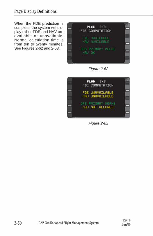
Page Display Definitions
2-50 GNS-XLS Enhanced Flight Management SystemRev. 0Jun/00
When the FDE prediction iscomplete, the system will dis-play either FDE and NAV areavailable or unavailable.Normal calculation time isfrom ten to twenty minutes.See Figures 2-62 and 2-63.
FDE COMPUTATION
FDE AVAILABLE
NAV AVAILABLE
GPS PRIMARY MEANS
NAV OK
PLAN 8/8
Figure 2-62
FDE COMPUTATION
FDE UNAVAILABLE
NAV UNAVAILABLE
GPS PRIMARY MEANS
NAV NOT ALLOWED
PLAN 8/8
Figure 2-63
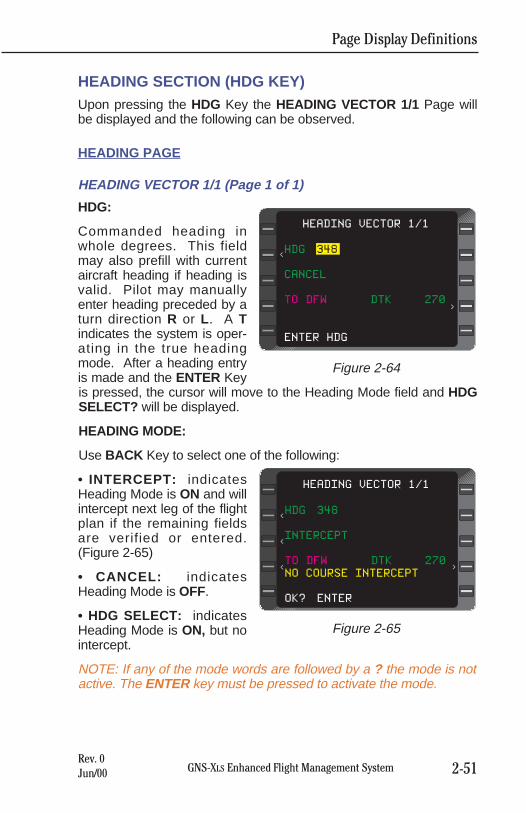
Page Display Definitions
2-51GNS-XLS Enhanced Flight Management SystemRev. 0Jun/00
HEADING SECTION (HDG KEY)Upon pressing the HDG Key the HEADING VECTOR 1/1 Page willbe displayed and the following can be observed.
HEADING PAGE
HEADING VECTOR 1/1 (Page 1 of 1)
HDG:
Commanded heading inwhole degrees. This fieldmay also prefill with currentaircraft heading if heading isvalid. Pilot may manuallyenter heading preceded by aturn direction R or L . A Tindicates the system is oper-ating in the true headingmode. After a heading entryis made and the ENTER Keyis pressed, the cursor will move to the Heading Mode field and HDGSELECT? will be displayed.
HEADING MODE:
Use BACK Key to select one of the following:
• INTERCEPT: indicatesHeading Mode is ON and willintercept next leg of the flightplan if the remaining fieldsare verified or entered.(Figure 2-65)
• CANCEL: indicatesHeading Mode is OFF.
• HDG SELECT: indicatesHeading Mode is ON, but nointercept.
NOTE: If any of the mode words are followed by a ? the mode is notactive. The ENTER key must be pressed to activate the mode.
HDG 348
CANCEL
TO DFW DTK 270
ENTER HDG
HEADING VECTOR 1/1
<
<
Figure 2-64
HDG 348
INTERCEPT
TO DFW DTK 270
NO COURSE INTERCEPT
OK? ENTER
HEADING VECTOR 1/1
>
<
<
<
Figure 2-65
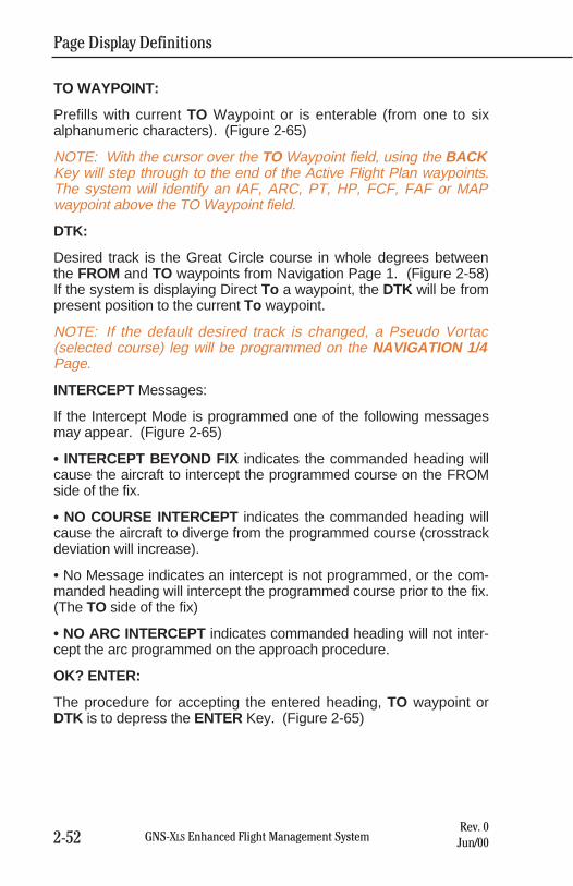
Page Display Definitions
2-52 GNS-XLS Enhanced Flight Management SystemRev. 0Jun/00
TO WAYPOINT:
Prefills with current TO Waypoint or is enterable (from one to sixalphanumeric characters). (Figure 2-65)
NOTE: With the cursor over the TO Waypoint field, using the BACKKey will step through to the end of the Active Flight Plan waypoints.The system will identify an IAF, ARC, PT, HP, FCF, FAF or MAPwaypoint above the TO Waypoint field.
DTK:
Desired track is the Great Circle course in whole degrees betweenthe FROM and TO waypoints from Navigation Page 1. (Figure 2-58)If the system is displaying Direct To a waypoint, the DTK will be frompresent position to the current To waypoint.
NOTE: If the default desired track is changed, a Pseudo Vortac(selected course) leg will be programmed on the NAVIGATION 1/4Page.
INTERCEPT Messages:
If the Intercept Mode is programmed one of the following messagesmay appear. (Figure 2-65)
• INTERCEPT BEYOND FIX indicates the commanded heading willcause the aircraft to intercept the programmed course on the FROMside of the fix.
• NO COURSE INTERCEPT indicates the commanded heading willcause the aircraft to diverge from the programmed course (crosstrackdeviation will increase).
• No Message indicates an intercept is not programmed, or the com-manded heading will intercept the programmed course prior to the fix.(The TO side of the fix)
• NO ARC INTERCEPT indicates commanded heading will not inter-cept the arc programmed on the approach procedure.
OK? ENTER:
The procedure for accepting the entered heading, TO waypoint orDTK is to depress the ENTER Key. (Figure 2-65)
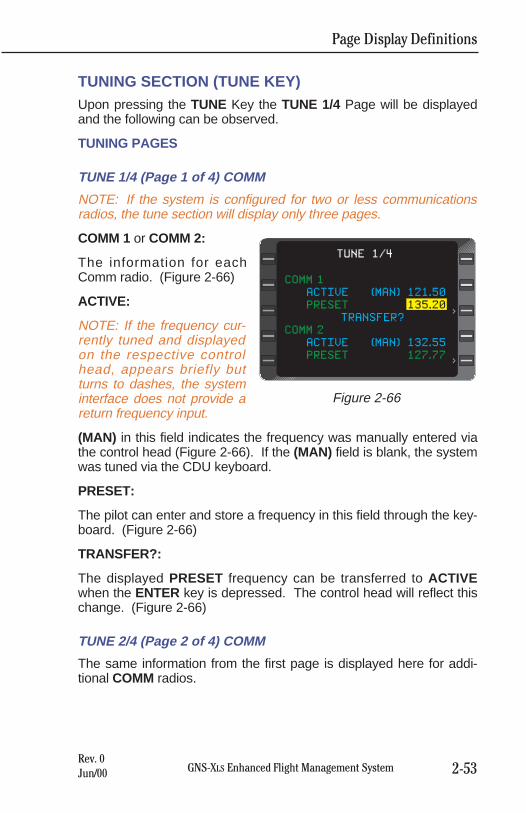
Page Display Definitions
2-53GNS-XLS Enhanced Flight Management SystemRev. 0Jun/00
TUNING SECTION (TUNE KEY)Upon pressing the TUNE Key the TUNE 1/4 Page will be displayedand the following can be observed.
TUNING PAGES
TUNE 1/4 (Page 1 of 4) COMM
NOTE: If the system is configured for two or less communicationsradios, the tune section will display only three pages.
COMM 1 or COMM 2:
The information for eachComm radio. (Figure 2-66)
ACTIVE:
NOTE: If the frequency cur-rently tuned and displayedon the respective controlhead, appears briefly butturns to dashes, the systeminterface does not provide areturn frequency input.
(MAN) in this field indicates the frequency was manually entered viathe control head (Figure 2-66). If the (MAN) field is blank, the systemwas tuned via the CDU keyboard.
PRESET:
The pilot can enter and store a frequency in this field through the key-board. (Figure 2-66)
TRANSFER?:
The displayed PRESET frequency can be transferred to ACTIVEwhen the ENTER key is depressed. The control head will reflect thischange. (Figure 2-66)
TUNE 2/4 (Page 2 of 4) COMM
The same information from the first page is displayed here for addi-tional COMM radios.
COMM 1
ACTIVE (MAN) 121.50
PRESET 135.20
TRANSFER?
COMM 2
ACTIVE (MAN) 132.55
PRESET 127.77
TUNE 1/4
>
>
Figure 2-66
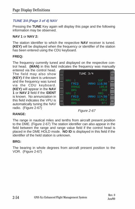
Page Display Definitions
2-54 GNS-XLS Enhanced Flight Management SystemRev. 0Jun/00
TUNE 3/4 (Page 3 of 4) NAV
Pressing the TUNE Key again will display this page and the followinginformation may be observed.
NAV 1 or NAV 2:
The station identifier to which the respective NAV receiver is tuned.(KEY) will be displayed when the frequency or identifier of the stationhas been entered using the CDU keyboard.
FREQ:
The frequency currently tuned and displayed on the respective con-trol head. (MAN) in this field indicates the frequency was manuallyentered via the control head.The field may also show(KEY) if the ident is unknownand the frequency was tunedvia the CDU keyboard.(KEY) will appear in the NAV1 or NAV 2 field if the IDENTis known. No annunciation inthis field indicates the VPU isautomatically tuning the NAVradio. (Figure 2-67)
RANGE:
The range in nautical miles and tenths from aircraft present positionto the DME. (Figure 2-67) The station identifier can also appear in thefield between the range and range value field if the control head isplaced in the DME HOLD mode. NO ID is displayed in this field if theidentifier of the held station is unknown.
BRG:
The bearing in whole degrees from aircraft present position to theVOR. (Figure 2-67)
NAV 1 SGF
FREQ (MAN) 116.90
RANGE 105.0
BRG 350
NAV 2 ARG
FREQ (MAN) 114.50
RANGE 109.2
BRG 071
TUNE 3/4
<
<
Figure 2-67
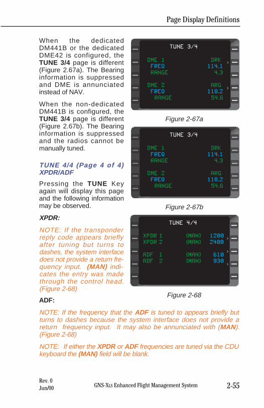
Page Display Definitions
2-55GNS-XLS Enhanced Flight Management SystemRev. 0Jun/00
When the dedicatedDM441B or the dedicatedDME42 is configured, theTUNE 3/4 page is different(Figure 2.67a). The Bearinginformation is suppressedand DME is annunciatedinstead of NAV.
When the non-dedicatedDM441B is configured, theTUNE 3/4 page is different(Figure 2.67b). The Bearinginformation is suppressedand the radios cannot bemanually tuned.
TUNE 4/4 (Page 4 of 4)XPDR/ADF
Pressing the TUNE Keyagain will display this pageand the following informationmay be observed.
XPDR:
NOTE: If the transponderreply code appears brieflyafter tuning but turns todashes, the system interfacedoes not provide a return fre-quency input. (MAN) indi-cates the entry was madethrough the control head.(Figure 2-68)
ADF:
NOTE: If the frequency that the ADF is tuned to appears briefly butturns to dashes because the system interface does not provide areturn frequency input. It may also be annunciated with (MAN).(Figure 2-68)
NOTE: If either the XPDR or ADF frequencies are tuned via the CDUkeyboard the (MAN) field will be blank.
DME 1 DRK
FREQ 114.1
RANGE 4.3
DME 2 ARG
FREQ 118.2
RANGE 54.6
TUNE 3/4
<
<
Figure 2-67a
DME 1 DRK
FREQ 114.1
RANGE 4.3
DME 2 ARG
FREQ 118.2
RANGE 54.6
TUNE 3/4
<
<
Figure 2-67b
XPDR 1 (MAN) 1200
XPDR 2 (MAN) 2400
ADF 1 (MAN) 610
ADF 2 (MAN) 930
TUNE 4/4
>
>
>
Figure 2-68
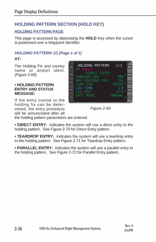
Page Display Definitions
2-56 GNS-XLS Enhanced Flight Management SystemRev. 0Jun/00
HOLDING PATTERN SECTION (HOLD KEY)
HOLDING PATTERN PAGE
This page is accessed by depressing the HOLD Key when the cursoris positioned over a Waypoint Identifier.
HOLDING PATTERN 1/1 (Page 1 of 1)AT:
The Holding Fix and countryname or airport ident.(Figure 2-69)
• HOLDING PATTERNENTRY AND STATUSMESSAGE:
If the entry course to theholding fix can be deter-mined, the entry procedurewill be annunciated after allthe holding pattern parameters are entered.
• DIRECT ENTRY: indicates the system will use a direct entry to theholding pattern. See Figure 2-70 for Direct Entry pattern.
• TEARDROP ENTRY: indicates the system will use a teardrop entryto the holding pattern. See Figure 2-71 for Teardrop Entry pattern.
• PARALLEL ENTRY: indicates the system will use a parallel entry tothe holding pattern. See Figure 2-72 for Parallel Entry pattern.
AT DILLY
DIRECT ENTRY
INBOUND CRS 305
MAX HOLDING TAS 261
TURN DIR RIGHT
LEG TIME 1.5
LEG DIS (4.4)
EXIT MODE MANUAL
HOLDING PATTERN 1/1
<
<
<
<
Figure 2-69
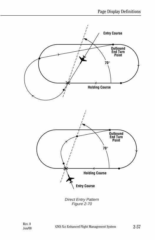
Page Display Definitions
2-57GNS-XLS Enhanced Flight Management SystemRev. 0Jun/00
70°
OutboundEnd Turn
Point
Holding Course
Entry Course
70°
OutboundEnd Turn
Point
Holding Course
Entry Course
Direct Entry Pattern Figure 2-70
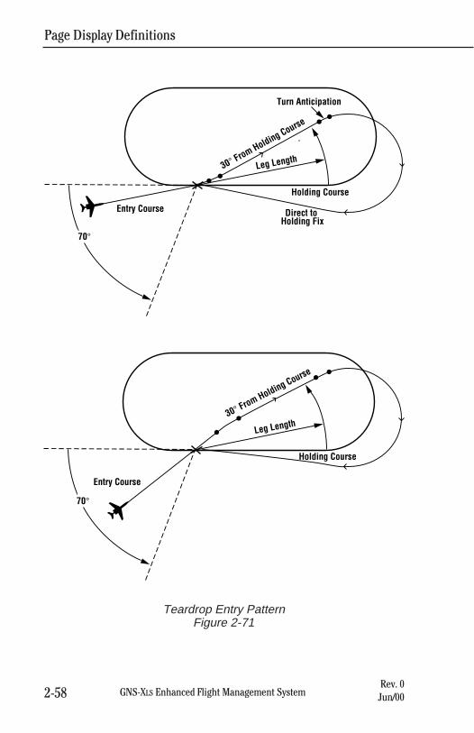
Page Display Definitions
2-58 GNS-XLS Enhanced Flight Management SystemRev. 0Jun/00
70°
Turn Anticipation
Holding Course
Leg Length30° From Holding Course
Direct to Holding Fix
Entry Course
70°
Holding Course
30° From Holding Course
Leg Length
Entry Course
Teardrop Entry Pattern Figure 2-71
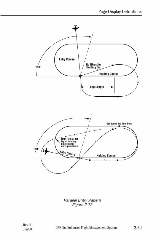
Page Display Definitions
2-59GNS-XLS Enhanced Flight Management SystemRev. 0Jun/00
Go Direct toHolding Fix
Leg Length
Holding Course
Entry Course
110°
Note Path of 1stlap of holding pattern after entry procedure
Holding CourseEntry Course
110°
Out Bound End Turn Point
Parallel Entry Pattern Figure 2-72
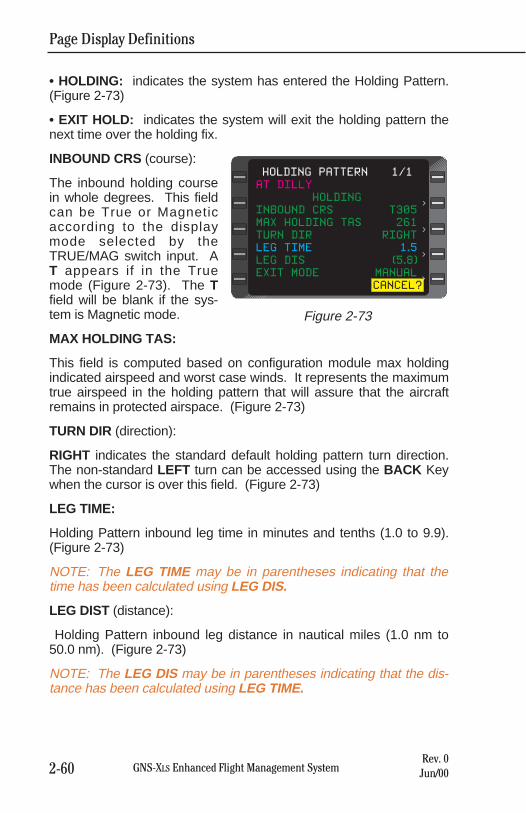
Page Display Definitions
2-60 GNS-XLS Enhanced Flight Management SystemRev. 0Jun/00
• HOLDING: indicates the system has entered the Holding Pattern.(Figure 2-73)
• EXIT HOLD: indicates the system will exit the holding pattern thenext time over the holding fix.
INBOUND CRS (course):
The inbound holding coursein whole degrees. This fieldcan be True or Magneticaccording to the displaymode selected by theTRUE/MAG switch input. AT appears if in the Truemode (Figure 2-73). The Tfield will be blank if the sys-tem is Magnetic mode.
MAX HOLDING TAS:
This field is computed based on configuration module max holdingindicated airspeed and worst case winds. It represents the maximumtrue airspeed in the holding pattern that will assure that the aircraftremains in protected airspace. (Figure 2-73)
TURN DIR (direction):
RIGHT indicates the standard default holding pattern turn direction.The non-standard LEFT turn can be accessed using the BACK Keywhen the cursor is over this field. (Figure 2-73)
LEG TIME:
Holding Pattern inbound leg time in minutes and tenths (1.0 to 9.9).(Figure 2-73)
NOTE: The LEG TIME may be in parentheses indicating that thetime has been calculated using LEG DIS.
LEG DIST (distance):
Holding Pattern inbound leg distance in nautical miles (1.0 nm to50.0 nm). (Figure 2-73)
NOTE: The LEG DIS may be in parentheses indicating that the dis-tance has been calculated using LEG TIME.
AT DILLY
HOLDING
INBOUND CRS T305
MAX HOLDING TAS 261
TURN DIR RIGHT
LEG TIME 1.5
LEG DIS (5.8)
EXIT MODE MANUAL
CANCEL?
HOLDING PATTERN 1/1
<
<
<
<
Figure 2-73
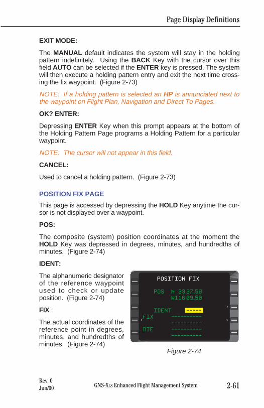
Page Display Definitions
2-61GNS-XLS Enhanced Flight Management SystemRev. 0Jun/00
EXIT MODE:
The MANUAL default indicates the system will stay in the holdingpattern indefinitely. Using the BACK Key with the cursor over thisfield AUTO can be selected if the ENTER key is pressed. The systemwill then execute a holding pattern entry and exit the next time cross-ing the fix waypoint. (Figure 2-73)
NOTE: If a holding pattern is selected an HP is annunciated next tothe waypoint on Flight Plan, Navigation and Direct To Pages.
OK? ENTER:
Depressing ENTER Key when this prompt appears at the bottom ofthe Holding Pattern Page programs a Holding Pattern for a particularwaypoint.
NOTE: The cursor will not appear in this field.
CANCEL:
Used to cancel a holding pattern. (Figure 2-73)
POSITION FIX PAGE
This page is accessed by depressing the HOLD Key anytime the cur-sor is not displayed over a waypoint.
POS:
The composite (system) position coordinates at the moment theHOLD Key was depressed in degrees, minutes, and hundredths ofminutes. (Figure 2-74)
IDENT:
The alphanumeric designatorof the reference waypointused to check or updateposition. (Figure 2-74)
FIX :
The actual coordinates of thereference point in degrees,minutes, and hundredths ofminutes. (Figure 2-74)
POS N 33 37.50
W116 09.50
IDENT -----
FIX ----------
----------
DIF ----------
----------
POSITION FIX
<
<
<
Figure 2-74
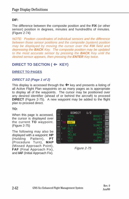
Page Display Definitions
2-62 GNS-XLS Enhanced Flight Management SystemRev. 0Jun/00
DIF:
The difference between the composite position and the FIX (or othersensor) position in degrees, minutes and hundredths of minutes.(Figure 2-74)
NOTE: Position coordinates of individual sensors and the differencebetween those sensor positions and the composite (system) positionmay be displayed by moving the cursor over the FIX field anddepressing the BACK Key. The composite position may be updatedto the most accurate sensor by pressing the BACK Key until thedesired sensor appears, then pressing the ENTER Key twice.
DIRECT TO SECTION ( d KEY)
DIRECT TO PAGES
DIRECT 1/2 (Page 1 of 2)
This display is accessed through the d key and presents a listing ofall Active Flight Plan waypoints on as many pages as is appropriateto display all of the waypoints. The cursor may be positioned overany desired identifier (ahead of or behind the aircraft) to proceedDIRECT (Figure 2-75). A new waypoint may be added to the flightplan to proceed direct.
TO:
When this page is accessed,the cursor is displayed overthe current TO waypoint.(Figure 2-75)
The following may also bedisplayed with a waypoint: HP(Holding Pattern), PT(Procedure Turn), MAP(Missed Approach Point),FAF (Final Approach Fix),and IAF (Initial Approach Fix).
KDAL BOSEY
DFW BULEY
TO HART HNN
19DFW SUMET
HP ELD AIR
MEI CYN
DELBE BUONO
VUZ DPK
VZV GWENY
DIRECT 1/2
<
<
<
<
<
<
<
<
<
<
Figure 2-75
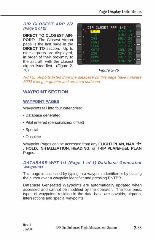
Page Display Definitions
2-63GNS-XLS Enhanced Flight Management SystemRev. 0Jun/00
DIR CLOSEST ARP 2/2(Page 2 of 2)
DIRECT TO CLOSEST AIR-PORT: The Closest Airportpage is the last page in theDIRECT TO section. Up tonine airports are displayed,in order of their proximity tothe aircraft, with the closestairport listed first. (Figure 2-76)
NOTE: Airports listed from the database on this page have runways3000 ft long or greater and are hard surfaced.
WAYPOINT SECTION
WAYPOINT PAGES
Waypoints fall into four categories:
• Database generated
• Pilot entered (personalized/ offset)
• Special
• Obsolete
Waypoint Pages can be accessed from any FLIGHT PLAN, NAV, d, HOLD, INITIALIZATION, HEADING, or TRIP PLAN/FUEL PLANPages.
DATABASE WPT 1/1 (Page 1 of 1) Database GeneratedWaypoints
This page is accessed by typing in a waypoint identifier or by placingthe cursor over a waypoint identifier and pressing ENTER.
Database Generated Waypoints are automatically updated whenaccessed and cannot be modified by the operator. The four basictypes of waypoints residing in the data base are navaids, airports,intersections and special waypoints.
TO 312 344/ 10
I18 045/ 14
I43 301/ 29
KUNI 344/ 29
KCRW 141/ 31
KHTS 230/ 34
I28 254/ 35
KPMH 281/ 39
KPKB 040/ 45
DIR CLOSET ARP 1/2
>
<
<
<
<
<
<
<
<
<
Figure 2-76
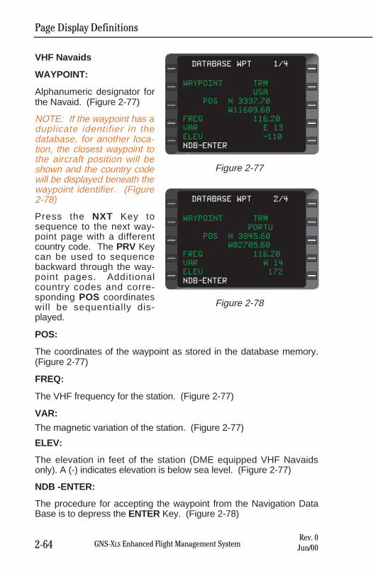
VHF Navaids
WAYPOINT:
Alphanumeric designator forthe Navaid. (Figure 2-77)
NOTE: If the waypoint has aduplicate identifier in thedatabase, for another loca-tion, the closest waypoint tothe aircraft position will beshown and the country codewill be displayed beneath thewaypoint identifier. (Figure2-78)
Press the NXT Key tosequence to the next way-point page with a differentcountry code. The PRV Keycan be used to sequencebackward through the way-point pages. Additionalcountry codes and corre-sponding POS coordinateswill be sequentially dis-played.
POS:
The coordinates of the waypoint as stored in the database memory.(Figure 2-77)
FREQ:
The VHF frequency for the station. (Figure 2-77)
VAR:
The magnetic variation of the station. (Figure 2-77)
ELEV:
The elevation in feet of the station (DME equipped VHF Navaidsonly). A (-) indicates elevation is below sea level. (Figure 2-77)
NDB -ENTER:
The procedure for accepting the waypoint from the Navigation DataBase is to depress the ENTER Key. (Figure 2-78)
Page Display Definitions
2-64 GNS-XLS Enhanced Flight Management SystemRev. 0Jun/00
WAYPOINT TRM
PORTU
POS N 3845.60
W02705.60
FREQ 116.20
VAR W 14
ELEV 172
NDB-ENTER
DATABASE WPT 2/4
Figure 2-78
WAYPOINT TRM
USA
POS N 3337.70
W11609.60
FREQ 116.20
VAR E 13
ELEV -110
NDB-ENTER
DATABASE WPT 1/4
Figure 2-77
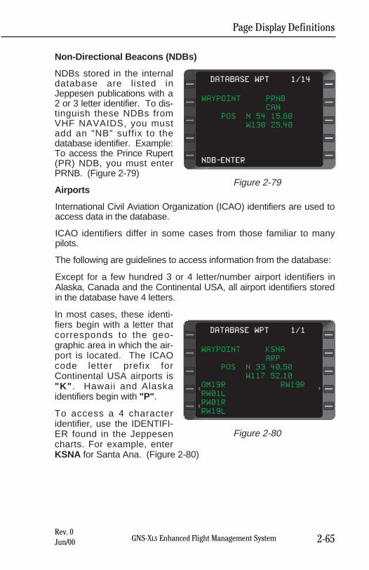
Page Display Definitions
2-65GNS-XLS Enhanced Flight Management SystemRev. 0Jun/00
Non-Directional Beacons (NDBs)
NDBs stored in the internaldatabase are listed inJeppesen publications with a2 or 3 letter identifier. To dis-tinguish these NDBs fromVHF NAVAIDS, you mustadd an "NB" suffix to thedatabase identifier. Example:To access the Prince Rupert(PR) NDB, you must enterPRNB. (Figure 2-79)
Airports
International Civil Aviation Organization (ICAO) identifiers are used toaccess data in the database.
ICAO identifiers differ in some cases from those familiar to manypilots.
The following are guidelines to access information from the database:
Except for a few hundred 3 or 4 letter/number airport identifiers inAlaska, Canada and the Continental USA, all airport identifiers storedin the database have 4 letters.
In most cases, these identi-fiers begin with a letter thatcorresponds to the geo-graphic area in which the air-port is located. The ICAOcode letter prefix forContinental USA airports is"K" . Hawaii and Alaskaidentifiers begin with "P" .
To access a 4 characteridentifier, use the IDENTIFI-ER found in the Jeppesencharts. For example, enterKSNA for Santa Ana. (Figure 2-80)
WAYPOINT PRNB
CAN
POS N 54 15.80
W130 25.40
NDB-ENTER
DATABASE WPT 1/14
Figure 2-79
WAYPOINT KSNA
ARP
POS N 33 40.50
W117 52.10
OM19R RW19R
RW01L
RW01R
RW19L
DATABASE WPT 1/1
<
<
<
Figure 2-80
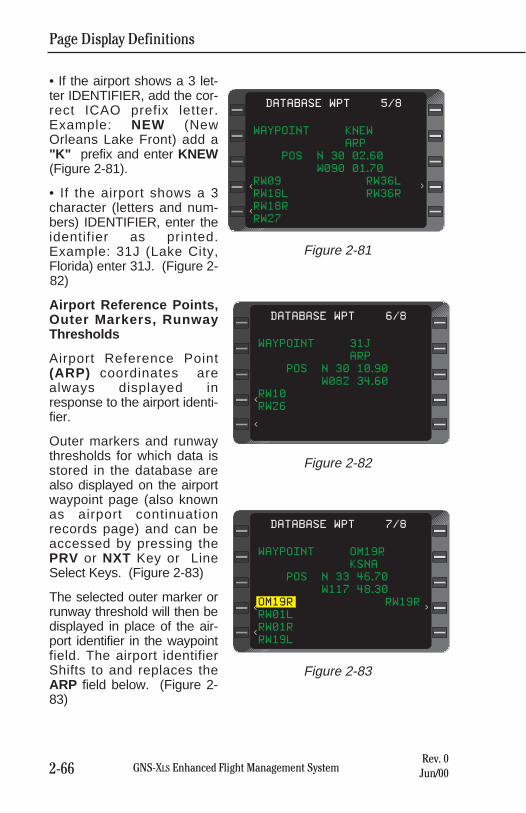
Page Display Definitions
2-66 GNS-XLS Enhanced Flight Management SystemRev. 0Jun/00
• If the airport shows a 3 let-ter IDENTIFIER, add the cor-rect ICAO prefix letter.Example: NEW (NewOrleans Lake Front) add a"K" prefix and enter KNEW(Figure 2-81).
• If the airport shows a 3character (letters and num-bers) IDENTIFIER, enter theidentifier as printed.Example: 31J (Lake City,Florida) enter 31J. (Figure 2-82)
Airport Reference Points,Outer Markers, RunwayThresholds
Airport Reference Point(ARP) coordinates arealways displayed inresponse to the airport identi-fier.
Outer markers and runwaythresholds for which data isstored in the database arealso displayed on the airportwaypoint page (also knownas airport continuationrecords page) and can beaccessed by pressing thePRV or NXT Key or LineSelect Keys. (Figure 2-83)
The selected outer marker orrunway threshold will then bedisplayed in place of the air-port identifier in the waypointfield. The airport identifierShifts to and replaces theARP field below. (Figure 2-83)
WAYPOINT KNEW
ARP
POS N 30 02.60
W090 01.70
RW09 RW36L
RW18L RW36R
RW18R
RW27
DATABASE WPT 5/8
<
<
<
Figure 2-81
WAYPOINT 31J
ARP
POS N 30 10.90
W082 34.60
RW10
RW26
DATABASE WPT 6/8
<
<
Figure 2-82
WAYPOINT OM19R
KSNA
POS N 33 46.70
W117 48.30
OM19R RW19R
RW01L
RW01R
RW19L
DATABASE WPT 7/8
<
<
<
Figure 2-83
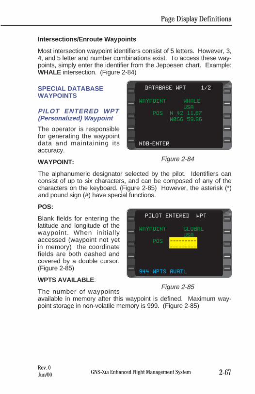
Page Display Definitions
2-67GNS-XLS Enhanced Flight Management SystemRev. 0Jun/00
Intersections/Enroute Waypoints
Most intersection waypoint identifiers consist of 5 letters. However, 3,4, and 5 letter and number combinations exist. To access these way-points, simply enter the identifier from the Jeppesen chart. Example:WHALE intersection. (Figure 2-84)
SPECIAL DATABASEWAYPOINTS
PILOT ENTERED WPT(Personalized) Waypoint
The operator is responsiblefor generating the waypointdata and maintaining itsaccuracy.
WAYPOINT:
The alphanumeric designator selected by the pilot. Identifiers canconsist of up to six characters, and can be composed of any of thecharacters on the keyboard. (Figure 2-85) However, the asterisk (*)and pound sign (#) have special functions.
POS:
Blank fields for entering thelatitude and longitude of thewaypoint. When initiallyaccessed (waypoint not yetin memory) the coordinatefields are both dashed andcovered by a double cursor.(Figure 2-85)
WPTS AVAILABLE :
The number of waypointsavailable in memory after this waypoint is defined. Maximum way-point storage in non-volatile memory is 999. (Figure 2-85)
WAYPOINT WHALE
USA
POS N 42 11.87
W066 59.96
NDB-ENTER
DATABASE WPT 1/2
Figure 2-84
WAYPOINT GLOBAL
USA
POS ---------
---------
944 WPTS AVAIL
PILOT ENTERED WPT
Figure 2-85
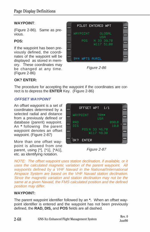
Page Display Definitions
2-68 GNS-XLS Enhanced Flight Management SystemRev. 0Jun/00
WAYPOINT:
(Figure 2-86). Same as pre-vious.
POS:
If the waypoint has been pre-viously defined, the coordi-nates of the waypoint will bedisplayed as stored in mem-ory. These coordinates maybe changed at any time.(Figure 2-86)
OK? ENTER:
The procedure for accepting the waypoint if the coordinates are cor-rect is to depress the ENTER Key. (Figure 2-86)
OFFSET WAYPOINT
An offset waypoint is a set ofcoordinates determined by aselected radial and distancefrom a previously defined ordatabase (parent) waypoint.An * following the parentwaypoint denotes an offsetwaypoint. (Figure 2-87)
More than one offset way-point is allowed from oneparent, using [*], [*1], [*A1],etc. as identifying notation.
NOTE: The offset waypoint uses station declination, if available, or ituses the calculated magnetic variation of the parent waypoint. Allwaypoints defined by a VHF Navaid in the National/InternationalAirspace System are based on the VHF Navaid station declination.Since the magnetic variation and station declination may not be thesame at a given Navaid, the FMS calculated position and the definedposition may differ.
WAYPOINT:
The parent waypoint identifier followed by an *. When an offset way-point identifier is entered and the waypoint has not been previouslydefined, the RAD, DIS, and POS fields are all dashed.
WAYPOINT TRM*
USA
RAD 090.0
DIS 10.0
POS N 33 46.70
W117 48.30
OK? ENTER
OFFSET WPT 1/1
>
<
Figure 2-87
WAYPOINT GLOBAL
USA
POS N 33 39.70
W117 51.00
944 WPTS AVAIL
PILOT ENTERED WPT
Figure 2-86
Page Display Definitions
2-69GNS-XLS Enhanced Flight Management SystemRev. 0Jun/00
When the waypoint has been previously defined the coordinates willbe displayed and the radial and distance values will be computedbased on the location of the parent waypoint. (Figure 2-87)
If the parent waypoint is a waypoint from an airport continuationrecord (runway or outer marker associated with a specific airport), theairport identifier will be displayed immediately below the offset way-point identifier.
If a parent waypoint has a duplicate identifier in the database, thecountry code will be displayed immediately below the offset waypointidentifier. (Figure 2-87)
RAD:
The radial from the parent waypoint in degrees and tenths of degrees,along which the offset is established. This entry will be annunciatedwith a T if a true heading input is received or if the parent waypoint isnorth of N 70° or south of S 60° latitude. (Figure 2-87)
NOTE: The radial can be entered in whole numbers without a trailing0. i.e. enter 070 or 70 and 070.0 will be displayed. To enter a tenth ofa radial all 4 digits must be entered. i.e. 0701 will be displayed as070.1. The DIS entry requires a trailing 0 be entered for any DISvalue greater than .9. i.e. enter 100 to display 10.0.
DIS:
The distance from the parent waypoint to the offset waypoint (1999.9maximum enterable). (Figure 2-87)
POS:
The computed offset waypoint coordinates based on the pilot enteredradial and distance from the parent waypoint. (Figure 2-87)
OK? ENTER:
The procedure for accepting the waypoint if the coordinates are cor-rect is to depress the ENTER Key. (Figure 2-87)
SPECIAL WAYPOINTS
#0,#1 and #OFF are special waypoints defined automatically by thesystem based on the airplane position.
#0 After pressing the d key and ENTER key the position after theturn where the airplane intercepts the course to the direct to waypoint.The #0 waypoint is defined as the point from which a DIRECT TOwaypoint leg has begun. Should the DIRECT TO procedure require a
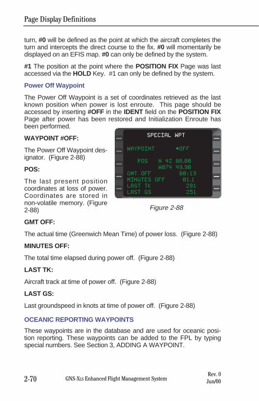
Page Display Definitions
2-70 GNS-XLS Enhanced Flight Management SystemRev. 0Jun/00
turn, #0 will be defined as the point at which the aircraft completes theturn and intercepts the direct course to the fix. #0 will momentarily bedisplayed on an EFIS map. #0 can only be defined by the system.
#1 The position at the point where the POSITION FIX Page was lastaccessed via the HOLD Key. #1 can only be defined by the system.
Power Off Waypoint
The Power Off Waypoint is a set of coordinates retrieved as the lastknown position when power is lost enroute. This page should beaccessed by inserting #OFF in the IDENT field on the POSITION FIXPage after power has been restored and Initialization Enroute hasbeen performed.
WAYPOINT #OFF:
The Power Off Waypoint des-ignator. (Figure 2-88)
POS:
The last present positioncoordinates at loss of power.Coordinates are stored innon-volatile memory. (Figure2-88)
GMT OFF:
The actual time (Greenwich Mean Time) of power loss. (Figure 2-88)
MINUTES OFF:
The total time elapsed during power off. (Figure 2-88)
LAST TK:
Aircraft track at time of power off. (Figure 2-88)
LAST GS:
Last groundspeed in knots at time of power off. (Figure 2-88)
OCEANIC REPORTING WAYPOINTS
These waypoints are in the database and are used for oceanic posi-tion reporting. These waypoints can be added to the FPL by typingspecial numbers. See Section 3, ADDING A WAYPOINT.
WAYPOINT *OFF
POS N 42 08.00
W074 49.90
GMT OFF 00:13
MINUTES OFF 01.1
LAST TK 281
LAST GS 251
SPECIAL WPT
Figure 2-88
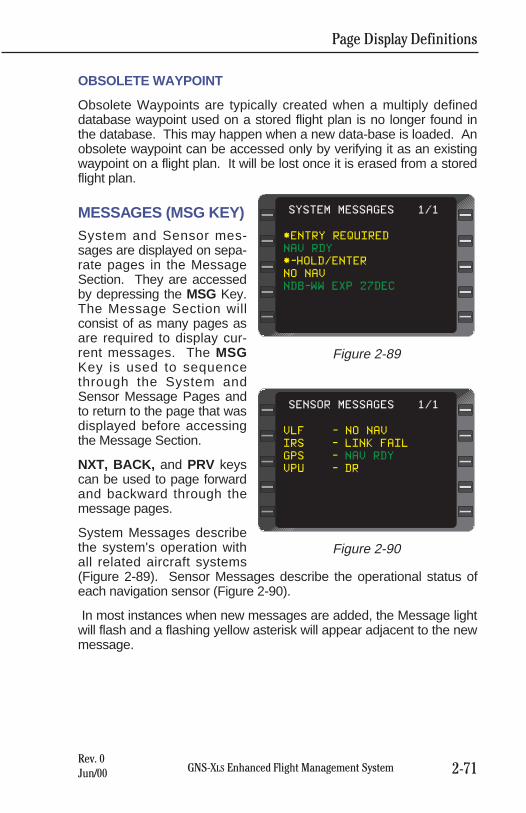
Page Display Definitions
2-71GNS-XLS Enhanced Flight Management SystemRev. 0Jun/00
OBSOLETE WAYPOINT
Obsolete Waypoints are typically created when a multiply defineddatabase waypoint used on a stored flight plan is no longer found inthe database. This may happen when a new data-base is loaded. Anobsolete waypoint can be accessed only by verifying it as an existingwaypoint on a flight plan. It will be lost once it is erased from a storedflight plan.
MESSAGES (MSG KEY)System and Sensor mes-sages are displayed on sepa-rate pages in the MessageSection. They are accessedby depressing the MSG Key.The Message Section willconsist of as many pages asare required to display cur-rent messages. The MSGKey is used to sequencethrough the System andSensor Message Pages andto return to the page that wasdisplayed before accessingthe Message Section.
NXT, BACK, and PRV keyscan be used to page forwardand backward through themessage pages.
System Messages describethe system's operation withall related aircraft systems(Figure 2-89). Sensor Messages describe the operational status ofeach navigation sensor (Figure 2-90).
In most instances when new messages are added, the Message lightwill flash and a flashing yellow asterisk will appear adjacent to the newmessage.
*ENTRY REQUIRED
NAV RDY
*-HOLD/ENTER
NO NAV
NDB-WW EXP 27DEC
SYSTEM MESSAGES 1/1
Figure 2-89
VLF - NO NAV
IRS - LINK FAIL
GPS - NAV RDY
VPU - DR
SENSOR MESSAGES 1/1
Figure 2-90
Page Display Definitions
2-72 GNS-XLS Enhanced Flight Management SystemRev. 0Jun/00
SYSTEM MESSAGES
ACTION REQUIRED:
The following are the action required messages that may appear onthe SYSTEM MESSAGES Page. All will cause the message annun-ciator to flash.
System Message Explanation
ENTRY REQUIRED Information required on the InitializationPage must be verified/entered. (Date, GMTand Position).
VERIFY POSITION Aircraft composite (blended) position is inquestion and must be manually verified.
VAR WARNING Magnetic variation cannot be automaticallycomputed, and MAN VAR REQD. A manualvariation entry must be made on NAV Page3 (i. e. aircraft position is north of 70° N lati-tude or south of 60° S latitude).
ADVISORY:
The following are the advisory messages that may appear on theSYSTEM MESSAGES Page. All will cause the message annuncia-tor to flash unless otherwise noted with an asterisk *.
System Message Explanation
AFIS LINK FAIL For AFIS equipped operation, communica-tion to the AFIS DMU has failed.
AFIS XFER FAIL For AFIS equipped operation, a flight plantransfer from the AFIS DMU to the FMS hasfailed.
ALTITUDE FAIL The altitude input to the system has failed.
*APRCH ARMED Approach is ready to be executed. Pressing ENTER TO CANCEL? ENTER will cancel the sequence. Displayed
within 30NM radius of the airport. CDI sensi-tivity changes to 1NM full scale deflection. VNAV Deviation changes to 500 ft. full scaledeflection. The message annunciator will not illuminate.
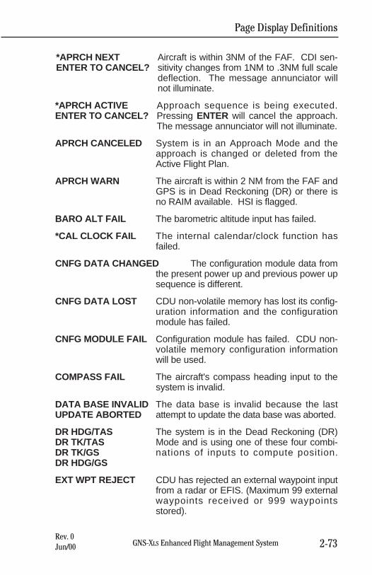
Page Display Definitions
2-73GNS-XLS Enhanced Flight Management SystemRev. 0Jun/00
*APRCH NEXT Aircraft is within 3NM of the FAF. CDI sen-ENTER TO CANCEL? sitivity changes from 1NM to .3NM full scale
deflection. The message annunciator will not illuminate.
*APRCH ACTIVE Approach sequence is being executed. ENTER TO CANCEL? Pressing ENTER will cancel the approach.
The message annunciator will not illuminate.
APRCH CANCELED System is in an Approach Mode and theapproach is changed or deleted from theActive Flight Plan.
APRCH WARN The aircraft is within 2 NM from the FAF andGPS is in Dead Reckoning (DR) or there isno RAIM available. HSI is flagged.
BARO ALT FAIL The barometric altitude input has failed.
*CAL CLOCK FAIL The internal calendar/clock function hasfailed.
CNFG DATA CHANGED The configuration module data fromthe present power up and previous power upsequence is different.
CNFG DATA LOST CDU non-volatile memory has lost its config-uration information and the configurationmodule has failed.
CNFG MODULE FAIL Configuration module has failed. CDU non-volatile memory configuration informationwill be used.
COMPASS FAIL The aircraft's compass heading input to thesystem is invalid.
DATA BASE INVALID The data base is invalid because the last UPDATE ABORTED attempt to update the data base was aborted.
DR HDG/TAS The system is in the Dead Reckoning (DR) DR TK/TAS Mode and is using one of these four combi-DR TK/GS nations of inputs to compute position. DR HDG/GS
EXT WPT REJECT CDU has rejected an external waypoint inputfrom a radar or EFIS. (Maximum 99 externalwaypoints received or 999 waypointsstored).
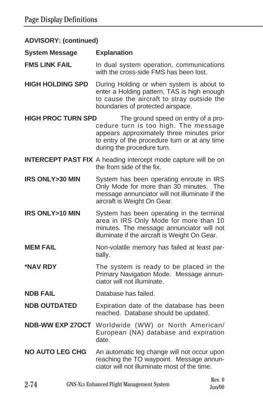
ADVISORY: (continued)
System Message Explanation
FMS LINK FAIL In dual system operation, communicationswith the cross-side FMS has been lost.
HIGH HOLDING SPD During Holding or when system is about toenter a Holding pattern, TAS is high enoughto cause the aircraft to stray outside theboundaries of protected airspace.
HIGH PROC TURN SPD The ground speed on entry of a pro-cedure turn is too high. The messageappears approximately three minutes priorto entry of the procedure turn or at any timeduring the procedure turn.
INTERCEPT PAST FIX A heading intercept mode capture will be onthe from side of the fix.
IRS ONLY>30 MIN System has been operating enroute in IRSOnly Mode for more than 30 minutes. Themessage annunciator will not illuminate if theaircraft is Weight On Gear.
IRS ONLY>10 MIN System has been operating in the terminalarea in IRS Only Mode for more than 10minutes. The message annunciator will notilluminate if the aircraft is Weight On Gear.
MEM FAIL Non-volatile memory has failed at least par-tially.
*NAV RDY The system is ready to be placed in thePrimary Navigation Mode. Message annun-ciator will not illuminate.
NDB FAIL Database has failed.
NDB OUTDATED Expiration date of the database has beenreached. Database should be updated.
NDB-WW EXP 27OCT Worldwide (WW) or North American/European (NA) database and expirationdate.
NO AUTO LEG CHG An automatic leg change will not occur uponreaching the TO waypoint. Message annun-ciator will not illuminate most of the time.
Page Display Definitions
2-74 GNS-XLS Enhanced Flight Management SystemRev. 0Jun/00
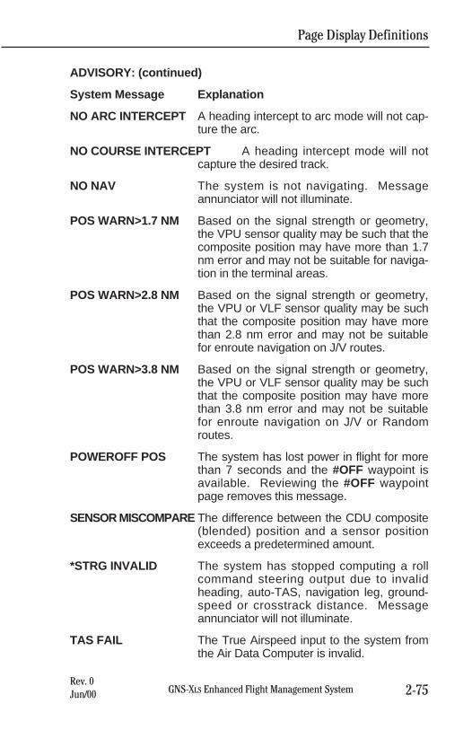
Page Display Definitions
2-75GNS-XLS Enhanced Flight Management SystemRev. 0Jun/00
ADVISORY: (continued)
System Message Explanation
NO ARC INTERCEPT A heading intercept to arc mode will not cap-ture the arc.
NO COURSE INTERCEPT A heading intercept mode will notcapture the desired track.
NO NAV The system is not navigating. Messageannunciator will not illuminate.
POS WARN>1.7 NM Based on the signal strength or geometry,the VPU sensor quality may be such that thecomposite position may have more than 1.7nm error and may not be suitable for naviga-tion in the terminal areas.
POS WARN>2.8 NM Based on the signal strength or geometry,the VPU or VLF sensor quality may be suchthat the composite position may have morethan 2.8 nm error and may not be suitablefor enroute navigation on J/V routes.
POS WARN>3.8 NM Based on the signal strength or geometry,the VPU or VLF sensor quality may be suchthat the composite position may have morethan 3.8 nm error and may not be suitablefor enroute navigation on J/V or Randomroutes.
POWEROFF POS The system has lost power in flight for morethan 7 seconds and the #OFF waypoint isavailable. Reviewing the #OFF waypointpage removes this message.
SENSOR MISCOMPARE The difference between the CDU composite(blended) position and a sensor positionexceeds a predetermined amount.
*STRG INVALID The system has stopped computing a rollcommand steering output due to invalidheading, auto-TAS, navigation leg, ground-speed or crosstrack distance. Messageannunciator will not illuminate.
TAS FAIL The True Airspeed input to the system fromthe Air Data Computer is invalid.
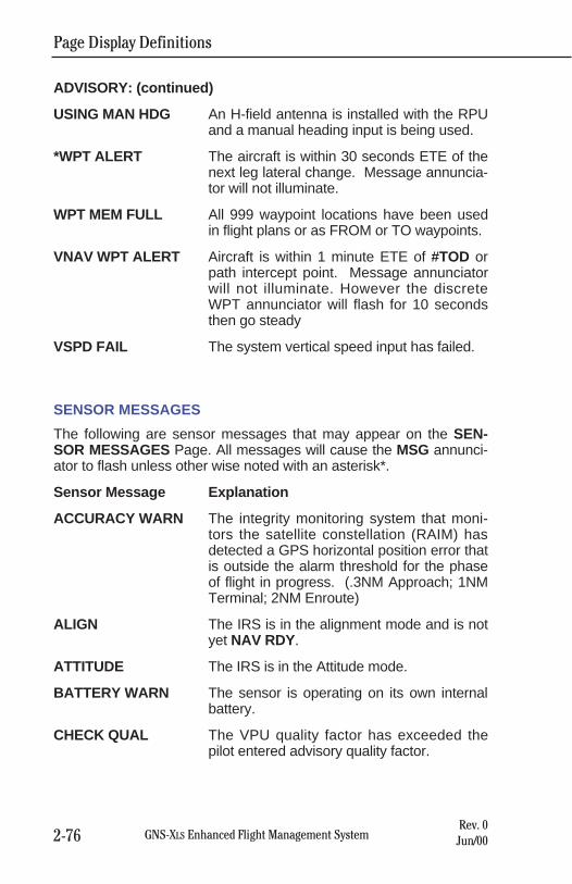
ADVISORY: (continued)
USING MAN HDG An H-field antenna is installed with the RPUand a manual heading input is being used.
*WPT ALERT The aircraft is within 30 seconds ETE of thenext leg lateral change. Message annuncia-tor will not illuminate.
WPT MEM FULL All 999 waypoint locations have been usedin flight plans or as FROM or TO waypoints.
VNAV WPT ALERT Aircraft is within 1 minute ETE of #TOD orpath intercept point. Message annunciatorwill not illuminate. However the discreteWPT annunciator will flash for 10 secondsthen go steady
VSPD FAIL The system vertical speed input has failed.
SENSOR MESSAGES
The following are sensor messages that may appear on the SEN-SOR MESSAGES Page. All messages will cause the MSG annunci-ator to flash unless other wise noted with an asterisk*.
Sensor Message Explanation
ACCURACY WARN The integrity monitoring system that moni-tors the satellite constellation (RAIM) hasdetected a GPS horizontal position error thatis outside the alarm threshold for the phaseof flight in progress. (.3NM Approach; 1NMTerminal; 2NM Enroute)
ALIGN The IRS is in the alignment mode and is notyet NAV RDY.
ATTITUDE The IRS is in the Attitude mode.
BATTERY WARN The sensor is operating on its own internalbattery.
CHECK QUAL The VPU quality factor has exceeded thepilot entered advisory quality factor.
Page Display Definitions
2-76 GNS-XLS Enhanced Flight Management SystemRev. 0Jun/00
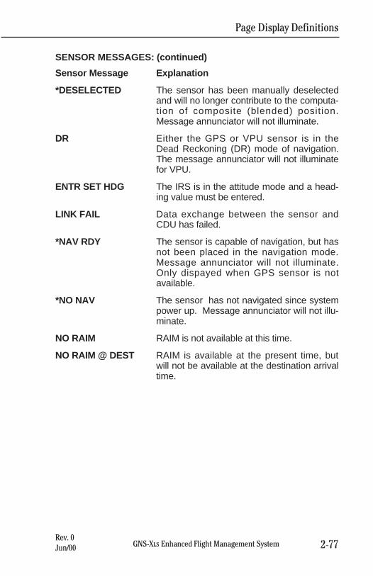
SENSOR MESSAGES: (continued)
Sensor Message Explanation
*DESELECTED The sensor has been manually deselectedand will no longer contribute to the computa-tion of composite (blended) position.Message annunciator will not illuminate.
DR Either the GPS or VPU sensor is in theDead Reckoning (DR) mode of navigation.The message annunciator will not illuminatefor VPU.
ENTR SET HDG The IRS is in the attitude mode and a head-ing value must be entered.
LINK FAIL Data exchange between the sensor andCDU has failed.
*NAV RDY The sensor is capable of navigation, but hasnot been placed in the navigation mode.Message annunciator will not illuminate.Only dispayed when GPS sensor is notavailable.
*NO NAV The sensor has not navigated since systempower up. Message annunciator will not illu-minate.
NO RAIM RAIM is not available at this time.
NO RAIM @ DEST RAIM is available at the present time, butwill not be available at the destination arrivaltime.
Page Display Definitions
2-77GNS-XLS Enhanced Flight Management SystemRev. 0Jun/00

Page Display Definitions
2-78 GNS-XLS Enhanced Flight Management SystemRev. 0Jun/00
THIS PAGE INTENTIONALLY LEFT BLANK
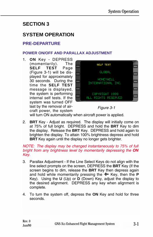
System Operation
3-1GNS-XLS Enhanced Flight Management SystemRev. 0Jun/00
SECTION 3
SYSTEM OPERATION
PRE-DEPARTURE
POWER ON/OFF AND PARALLAX ADJUSTMENT
1. ON Key - DEPRESS(momentarily). TheSELF TEST Page(Figure 3-1) will be dis-played for approximately30 seconds. During thetime the SELF TESTmessage is displayed,the system is performinginternal self tests. If thesystem was turned OFFlast by the removal of air-craft power, the systemwill turn ON automatically when aircraft power is applied.
2. BRT Key - Adjust as required. The display will initially come onat 75% of full bright. DEPRESS and hold the BRT Key to dimthe display. Release the BRT Key. DEPRESS and hold again tobrighten the display. To attain 100% brightness depress and holdBRT Key again until the display no longer gets brighter.
NOTE: The display may be changed instantaneously to 75% of fullbright from any brightness level by momentarily depressing the ONKey.
3. Parallax Adjustment - If the Line Select Keys do not align with theline select prompts on the screen, DEPRESS the BRT Key (If thescreen begins to dim, release the BRT Key then depress againand hold while momentarily pressing the d Key, then the PKey). Using the U (Up) or D (Down) Key, adjust the display tothe desired alignment. DEPRESS any key when alignment iscomplete.
4. To turn the system off, depress the ON Key and hold for threeseconds.
SELF TEST
GLOBAL
HONEYWELL
INTERNATIONAL INC.
COPYRIGHT 1999
ALL RIGHTS RESERVED
Figure 3-1
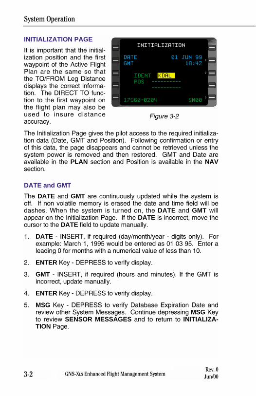
System Operation
3-2 GNS-XLS Enhanced Flight Management SystemRev. 0
Jun/00
INITIALIZATION PAGE
It is important that the initial-ization position and the firstwaypoint of the Active FlightPlan are the same so thatthe TO/FROM Leg Distancedisplays the correct informa-tion. The DIRECT TO func-tion to the first waypoint onthe flight plan may also beused to insure distanceaccuracy.
The Initialization Page gives the pilot access to the required initializa-tion data (Date, GMT and Position). Following confirmation or entryof this data, the page disappears and cannot be retrieved unless thesystem power is removed and then restored. GMT and Date areavailable in the PLAN section and Position is available in the NAVsection.
DATE and GMT
The DATE and GMT are continuously updated while the system isoff. If non volatile memory is erased the date and time field will bedashes. When the system is turned on, the DATE and GMT willappear on the Initialization Page. If the DATE is incorrect, move thecursor to the DATE field to update manually.
1. DATE - INSERT, if required (day/month/year - digits only). Forexample: March 1, 1995 would be entered as 01 03 95. Enter aleading 0 for months with a numerical value of less than 10.
2. ENTER Key - DEPRESS to verify display.
3. GMT - INSERT, if required (hours and minutes). If the GMT isincorrect, update manually.
4. ENTER Key - DEPRESS to verify display.
5. MSG Key - DEPRESS to verify Database Expiration Date andreview other System Messages. Continue depressing MSG Keyto review SENSOR MESSAGES and to return to INITIALIZA-TION Page.
DATE 01 JUN 99
GMT 18:42
IDENT KDAL
POS ----------
----------
17960-0204 SM00
INITIALIZATION
>
>
>
Figure 3-2
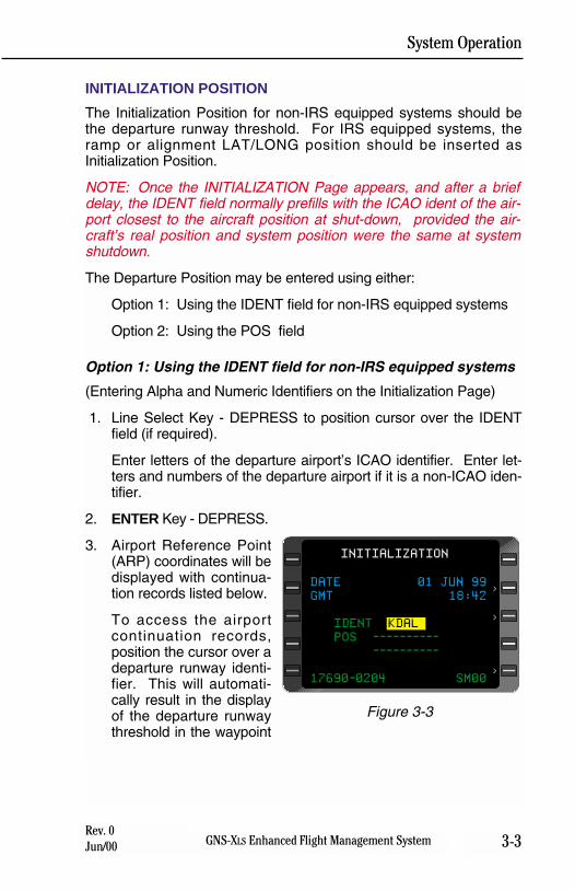
System Operation
3-3GNS-XLS Enhanced Flight Management SystemRev. 0Jun/00
INITIALIZATION POSITION
The Initialization Position for non-IRS equipped systems should bethe departure runway threshold. For IRS equipped systems, theramp or alignment LAT/LONG position should be inserted asInitialization Position.
NOTE: Once the INITIALIZATION Page appears, and after a briefdelay, the IDENT field normally prefills with the ICAO ident of the air-port closest to the aircraft position at shut-down, provided the air-craft’s real position and system position were the same at systemshutdown.
The Departure Position may be entered using either:
Option 1: Using the IDENT field for non-IRS equipped systems
Option 2: Using the POS field
Option 1: Using the IDENT field for non-IRS equipped systems
(Entering Alpha and Numeric Identifiers on the Initialization Page)
1. Line Select Key - DEPRESS to position cursor over the IDENTfield (if required).
Enter letters of the departure airport’s ICAO identifier. Enter let-ters and numbers of the departure airport if it is a non-ICAO iden-tifier.
2. ENTER Key - DEPRESS.
3. Airport Reference Point(ARP) coordinates will bedisplayed with continua-tion records listed below.
To access the airportcontinuation records,position the cursor over adeparture runway identi-fier. This will automati-cally result in the displayof the departure runwaythreshold in the waypoint
DATE 01 JUN 99
GMT 18:42
IDENT KDAL
POS ----------
----------
17690-0204 SM00
INITIALIZATION
>
>
>
Figure 3-3
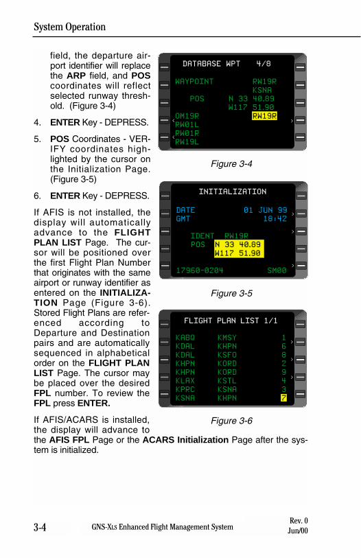
System Operation
3-4 GNS-XLS Enhanced Flight Management SystemRev. 0
Jun/00
field, the departure air-port identifier will replacethe ARP field, and POScoordinates will reflectselected runway thresh-old. (Figure 3-4)
4. ENTER Key - DEPRESS.
5. POS Coordinates - VER-IFY coordinates high-lighted by the cursor onthe Initialization Page.(Figure 3-5)
6. ENTER Key - DEPRESS.
If AFIS is not installed, thedisplay will automaticallyadvance to the FLIGHTPLAN LIST Page. The cur-sor will be positioned overthe first Flight Plan Numberthat originates with the sameairport or runway identifier asentered on the INITIALIZA-TION Page (Figure 3-6).Stored Flight Plans are refer-enced according toDeparture and Destinationpairs and are automaticallysequenced in alphabeticalorder on the FLIGHT PLANLIST Page. The cursor maybe placed over the desiredFPL number. To review theFPL press ENTER.
If AFIS/ACARS is installed,the display will advance tothe AFIS FPL Page or the ACARS Initialization Page after the sys-tem is initialized.
WAYPOINT RW19R
KSNA
POS N 33 40.89
W117 51.90
OM19R RW19R
RW01L
RW01R
RW19L
DATABASE WPT 4/8
><
<
Figure 3-4
DATE 01 JUN 99
GMT 18:42
IDENT RW19R
POS N 33 40.89
W117 51.90
17960-0204 SM00
INITIALIZATION
>
>
>
Figure 3-5
>
>KABQ KMSY 1
KDAL KHPN 6
KDAL KSFO 8
KHPN KORD 2
KHPN KORD 9
KLAX KSTL 4
KPRC KSNA 3
KSNA KHPN 7
>
FLIGHT PLAN LIST 1/1
Figure 3-6
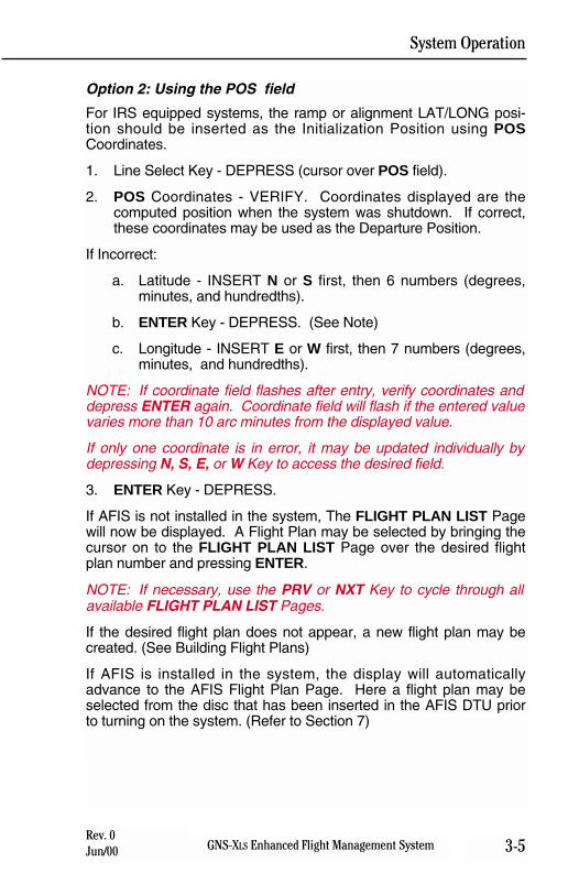
System Operation
3-5GNS-XLS Enhanced Flight Management SystemRev. 0Jun/00
Option 2: Using the POS field
For IRS equipped systems, the ramp or alignment LAT/LONG posi-tion should be inserted as the Initialization Position using POSCoordinates.
1. Line Select Key - DEPRESS (cursor over POS field).
2. POS Coordinates - VERIFY. Coordinates displayed are thecomputed position when the system was shutdown. If correct,these coordinates may be used as the Departure Position.
If Incorrect:
a. Latitude - INSERT N or S first, then 6 numbers (degrees,minutes, and hundredths).
b. ENTER Key - DEPRESS. (See Note)
c. Longitude - INSERT E or W first, then 7 numbers (degrees,minutes, and hundredths).
NOTE: If coordinate field flashes after entry, verify coordinates anddepress ENTER again. Coordinate field will flash if the entered valuevaries more than 10 arc minutes from the displayed value.
If only one coordinate is in error, it may be updated individually bydepressing N, S, E, or W Key to access the desired field.
3. ENTER Key - DEPRESS.
If AFIS is not installed in the system, The FLIGHT PLAN LIST Pagewill now be displayed. A Flight Plan may be selected by bringing thecursor on to the FLIGHT PLAN LIST Page over the desired flightplan number and pressing ENTER.
NOTE: If necessary, use the PRV or NXT Key to cycle through allavailable FLIGHT PLAN LIST Pages.
If the desired flight plan does not appear, a new flight plan may becreated. (See Building Flight Plans)
If AFIS is installed in the system, the display will automaticallyadvance to the AFIS Flight Plan Page. Here a flight plan may beselected from the disc that has been inserted in the AFIS DTU priorto turning on the system. (Refer to Section 7)

System Operation
3-6 GNS-XLS Enhanced Flight Management SystemRev. 0
Jun/00
THIS PAGE INTENTIONALLY LEFT BLANK
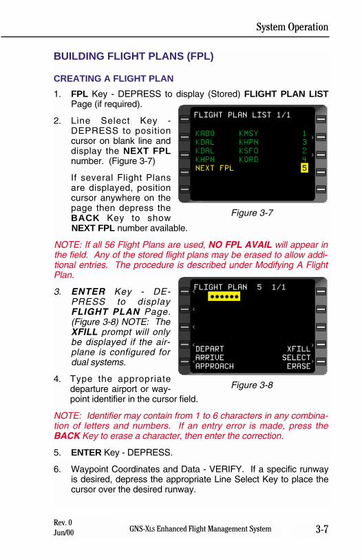
System Operation
3-7GNS-XLS Enhanced Flight Management SystemRev. 0Jun/00
BUILDING FLIGHT PLANS (FPL)
CREATING A FLIGHT PLAN
1. FPL Key - DEPRESS to display (Stored) FLIGHT PLAN LISTPage (if required).
2. Line Select Key -DEPRESS to positioncursor on blank line anddisplay the NEXT FPLnumber. (Figure 3-7)
If several Flight Plansare displayed, positioncursor anywhere on thepage then depress theBACK Key to showNEXT FPL number available.
NOTE: If all 56 Flight Plans are used, NO FPL AVAIL will appear inthe field. Any of the stored flight plans may be erased to allow addi-tional entries. The procedure is described under Modifying A FlightPlan.
3. ENTER Key - DE-PRESS to displayFLIGHT PLAN Page.(Figure 3-8) NOTE: TheXFILL prompt will onlybe displayed if the air-plane is configured fordual systems.
4. Type the appropriatedeparture airport or way-point identifier in the cursor field.
NOTE: Identifier may contain from 1 to 6 characters in any combina-tion of letters and numbers. If an entry error is made, press theBACK Key to erase a character, then enter the correction.
5. ENTER Key - DEPRESS.
6. Waypoint Coordinates and Data - VERIFY. If a specific runwayis desired, depress the appropriate Line Select Key to place thecursor over the desired runway.
KABQ KMSY 1
KDAL KHPN 3
KDAL KSFO 2
KHPN KORD 4
NEXT FPL 5
FLIGHT PLAN LIST 1/1
>
>
Figure 3-7
******
DEPART XFILL
ARRIVE SELECT
APPROACH ERASE
FLIGHT PLAN 5 1/1
><
<
<
<
<
>
Figure 3-8
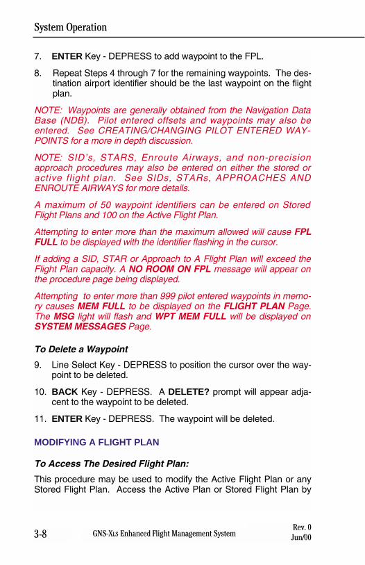
System Operation
3-8 GNS-XLS Enhanced Flight Management SystemRev. 0
Jun/00
7. ENTER Key - DEPRESS to add waypoint to the FPL.
8. Repeat Steps 4 through 7 for the remaining waypoints. The des-tination airport identifier should be the last waypoint on the flightplan.
NOTE: Waypoints are generally obtained from the Navigation DataBase (NDB). Pilot entered offsets and waypoints may also beentered. See CREATING/CHANGING PILOT ENTERED WAY-POINTS for a more in depth discussion.
NOTE: SID’s, STARS, Enroute Airways, and non-precisionapproach procedures may also be entered on either the stored oractive flight plan. See SIDs, STARs, APPROACHES ANDENROUTE AIRWAYS for more details.
A maximum of 50 waypoint identifiers can be entered on StoredFlight Plans and 100 on the Active Flight Plan.
Attempting to enter more than the maximum allowed will cause FPLFULL to be displayed with the identifier flashing in the cursor.
If adding a SID, STAR or Approach to A Flight Plan will exceed theFlight Plan capacity. A NO ROOM ON FPL message will appear onthe procedure page being displayed.
Attempting to enter more than 999 pilot entered waypoints in memo-ry causes MEM FULL to be displayed on the FLIGHT PLAN Page.The MSG light will flash and WPT MEM FULL will be displayed onSYSTEM MESSAGES Page.
To Delete a Waypoint
9. Line Select Key - DEPRESS to position the cursor over the way-point to be deleted.
10. BACK Key - DEPRESS. A DELETE? prompt will appear adja-cent to the waypoint to be deleted.
11. ENTER Key - DEPRESS. The waypoint will be deleted.
MODIFYING A FLIGHT PLAN
To Access The Desired Flight Plan:
This procedure may be used to modify the Active Flight Plan or anyStored Flight Plan. Access the Active Plan or Stored Flight Plan by
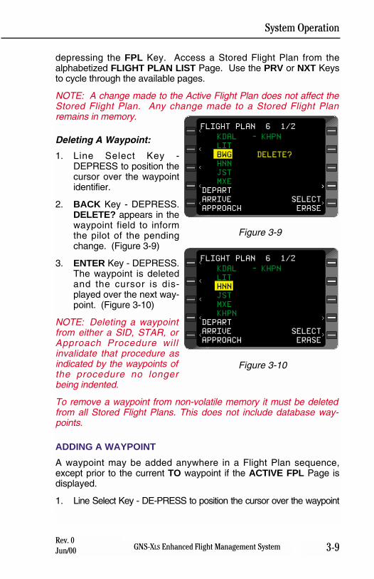
System Operation
3-9GNS-XLS Enhanced Flight Management SystemRev. 0Jun/00
depressing the FPL Key. Access a Stored Flight Plan from thealphabetized FLIGHT PLAN LIST Page. Use the PRV or NXT Keysto cycle through the available pages.
NOTE: A change made to the Active Flight Plan does not affect theStored Flight Plan. Any change made to a Stored Flight Planremains in memory.
Deleting A Waypoint:
1. Line Select Key -DEPRESS to position thecursor over the waypointidentifier.
2. BACK Key - DEPRESS.DELETE? appears in thewaypoint field to informthe pilot of the pendingchange. (Figure 3-9)
3. ENTER Key - DEPRESS.The waypoint is deletedand the cursor is dis-played over the next way-point. (Figure 3-10)
NOTE: Deleting a waypointfrom either a SID, STAR, orApproach Procedure willinvalidate that procedure asindicated by the waypoints ofthe procedure no longerbeing indented.
To remove a waypoint from non-volatile memory it must be deletedfrom all Stored Flight Plans. This does not include database way-points.
ADDING A WAYPOINT
A waypoint may be added anywhere in a Flight Plan sequence,except prior to the current TO waypoint if the ACTIVE FPL Page isdisplayed.
1. Line Select Key - DE-PRESS to position the cursor over the waypoint
KDAL - KHPN
LIT
BWG DELETE?
HNN
JST
MXE
DEPART
ARRIVE SELECT
APPROACH ERASE
FLIGHT PLAN 6 1/2
>><
<
<
<
<
>
Figure 3-9
KDAL - KHPN
LIT
HNN
JST
MXE
KHPN
DEPART
ARRIVE SELECT
APPROACH ERASE
FLIGHT PLAN 6 1/2
><
<
<
<
<
>
Figure 3-10
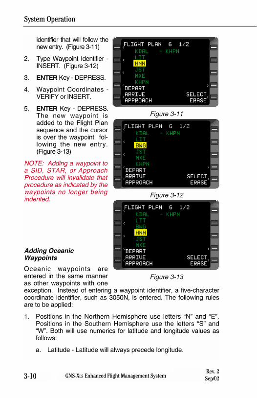
System Operation
3-10 GNS-XLS Enhanced Flight Management SystemRev. 2Sep/02
identifier that will follow thenew entry. (Figure 3-11)
2. Type Waypoint Identifier -INSERT. (Figure 3-12)
3. ENTER Key - DEPRESS.
4. Waypoint Coordinates -VERIFY or INSERT.
5. ENTER Key - DEPRESS.The new waypoint isadded to the Flight Plansequence and the cursoris over the waypoint fol-lowing the new entry.(Figure 3-13)
NOTE: Adding a waypoint toa SID, STAR, or ApproachProcedure will invalidate thatprocedure as indicated by thewaypoints no longer beingindented.
Adding OceanicWaypoints
Oceanic waypoints areentered in the same manneras other waypoints with oneexception. Instead of entering a waypoint identifier, a five-charactercoordinate identifier, such as 3050N, is entered. The following rulesare to be applied:
1. Positions in the Northern Hemisphere use letters “N” and “E”.Positions in the Southern Hemisphere use the letters “S” and“W”. Both will use numerics for latitude and longitude values asfollows:
a. Latitude - Latitude will always precede longitude.
KDAL - KHPN
LIT
HNN
JST
MXE
KHPN
DEPART
ARRIVE SELECT
APPROACH ERASE
FLIGHT PLAN 6 1/2
><
<
<
<
<
>
Figure 3-11
KDAL - KHPN
LIT
BWG
JST
MXE
KHPN
DEPART
ARRIVE SELECT
APPROACH ERASE
FLIGHT PLAN 6 1/2
><
<
<
<
<
>
Figure 3-12
KDAL - KHPN
LIT
BWG
HNN
JST
MXE
DEPART
ARRIVE SELECT
APPROACH ERASE
FLIGHT PLAN 6 1/2
><
<
<
<
<
>
Figure 3-13
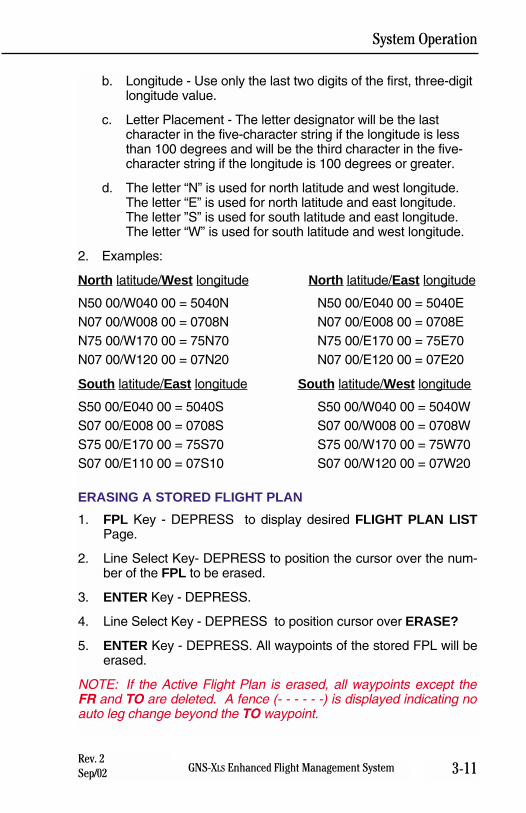
System Operation
3-11GNS-XLS Enhanced Flight Management SystemRev. 2Sep/02
b. Longitude - Use only the last two digits of the first, three-digit longitude value.
c. Letter Placement - The letter designator will be the last character in the five-character string if the longitude is less than 100 degrees and will be the third character in the five-character string if the longitude is 100 degrees or greater.
d. The letter “N” is used for north latitude and west longitude. The letter “E” is used for north latitude and east longitude. The letter ”S” is used for south latitude and east longitude. The letter “W” is used for south latitude and west longitude.
2. Examples:
North latitude/West longitude North latitude/East longitude
N50 00/W040 00 = 5040N N50 00/E040 00 = 5040EN07 00/W008 00 = 0708N N07 00/E008 00 = 0708EN75 00/W170 00 = 75N70 N75 00/E170 00 = 75E70N07 00/W120 00 = 07N20 N07 00/E120 00 = 07E20
South latitude/East longitude South latitude/West longitude
S50 00/E040 00 = 5040S S50 00/W040 00 = 5040WS07 00/E008 00 = 0708S S07 00/W008 00 = 0708WS75 00/E170 00 = 75S70 S75 00/W170 00 = 75W70S07 00/E110 00 = 07S10 S07 00/W120 00 = 07W20
ERASING A STORED FLIGHT PLAN
1. FPL Key - DEPRESS to display desired FLIGHT PLAN LISTPage.
2. Line Select Key- DEPRESS to position the cursor over the num-ber of the FPL to be erased.
3. ENTER Key - DEPRESS.
4. Line Select Key - DEPRESS to position cursor over ERASE?
5. ENTER Key - DEPRESS. All waypoints of the stored FPL will beerased.
NOTE: If the Active Flight Plan is erased, all waypoints except theFR and TO are deleted. A fence (- - - - - -) is displayed indicating noauto leg change beyond the TO waypoint.
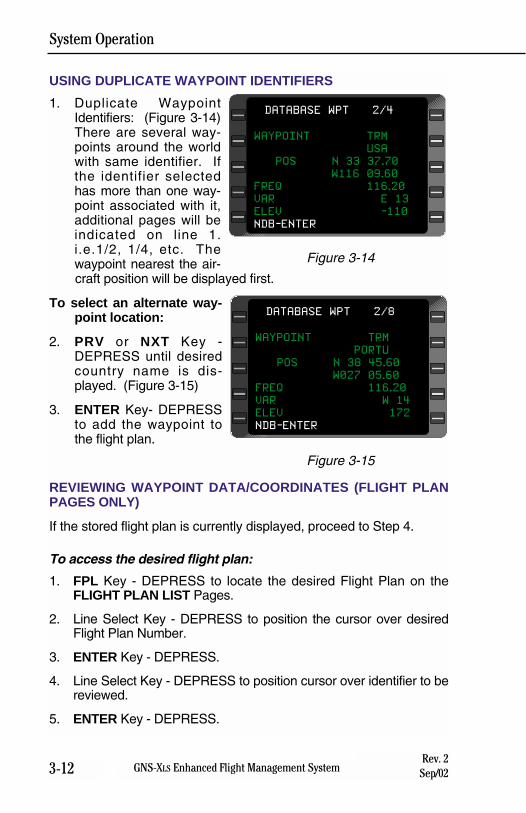
System Operation
3-12 GNS-XLS Enhanced Flight Management SystemRev. 2Sep/02
USING DUPLICATE WAYPOINT IDENTIFIERS
1. Duplicate WaypointIdentifiers: (Figure 3-14)There are several way-points around the worldwith same identifier. Ifthe identifier selectedhas more than one way-point associated with it,additional pages will beindicated on line 1.i.e.1/2, 1/4, etc. Thewaypoint nearest the air-craft position will be displayed first.
To select an alternate way-point location:
2. PRV or NXT Key -DEPRESS until desiredcountry name is dis-played. (Figure 3-15)
3. ENTER Key- DEPRESSto add the waypoint tothe flight plan.
REVIEWING WAYPOINT DATA/COORDINATES (FLIGHT PLANPAGES ONLY)
If the stored flight plan is currently displayed, proceed to Step 4.
To access the desired flight plan:
1. FPL Key - DEPRESS to locate the desired Flight Plan on theFLIGHT PLAN LIST Pages.
2. Line Select Key - DEPRESS to position the cursor over desiredFlight Plan Number.
3. ENTER Key - DEPRESS.
4. Line Select Key - DEPRESS to position cursor over identifier to bereviewed.
5. ENTER Key - DEPRESS.
WAYPOINT TRM
PORTU
POS N 38 45.60
W027 05.60
FREQ 116.20
VAR W 14
ELEV 172
NDB-ENTER
DATABASE WPT 2/8
Figure 3-15
WAYPOINT TRM
USA
POS N 33 37.70
W116 09.60
FREQ 116.20
VAR E 13
ELEV -110
NDB-ENTER
DATABASE WPT 2/4
Figure 3-14
System Operation
3-12aGNS-XLS Enhanced Flight Management SystemRev. 2Sep/02
6. Waypoint Coordinates or data- VERIFY.
7. ENTER Key - DEPRESS. The Flight Plan is displayed with thecursor over the next waypoint.
8. Repeat Steps 5 through 7 for remaining waypoints.
NOTE: This procedure may also be used for reviewing waypointinformation on the Active Flight Plan Page.
System Operation
3-12b GNS-XLS Enhanced Flight Management SystemRev. 2Sep/02
THIS PAGE INTENTIONALLY LEFT BLANK
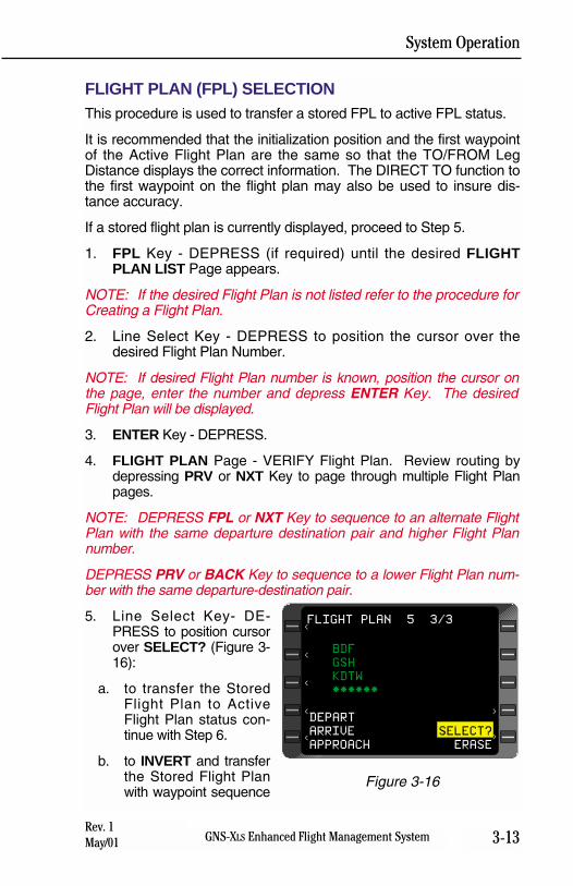
System Operation
3-13GNS-XLS Enhanced Flight Management SystemRev. 1May/01
FLIGHT PLAN (FPL) SELECTIONThis procedure is used to transfer a stored FPL to active FPL status.
It is recommended that the initialization position and the first waypointof the Active Flight Plan are the same so that the TO/FROM LegDistance displays the correct information. The DIRECT TO function tothe first waypoint on the flight plan may also be used to insure dis-tance accuracy.
If a stored flight plan is currently displayed, proceed to Step 5.
1. FPL Key - DEPRESS (if required) until the desired FLIGHTPLAN LIST Page appears.
NOTE: If the desired Flight Plan is not listed refer to the procedure forCreating a Flight Plan.
2. Line Select Key - DEPRESS to position the cursor over thedesired Flight Plan Number.
NOTE: If desired Flight Plan number is known, position the cursor onthe page, enter the number and depress ENTER Key. The desiredFlight Plan will be displayed.
3. ENTER Key - DEPRESS.
4. FLIGHT PLAN Page - VERIFY Flight Plan. Review routing bydepressing PRV or NXT Key to page through multiple Flight Planpages.
NOTE: DEPRESS FPL or NXT Key to sequence to an alternate FlightPlan with the same departure destination pair and higher Flight Plannumber.
DEPRESS PRV or BACK Key to sequence to a lower Flight Plan num-ber with the same departure-destination pair.
5. Line Select Key- DE-PRESS to position cursorover SELECT? (Figure 3-16):
a. to transfer the StoredFlight Plan to ActiveFlight Plan status con-tinue with Step 6.
b. to INVERT and transferthe Stored Flight Planwith waypoint sequence
BDF
GSH
KDTW
******
DEPART
ARRIVE SELECT?
APPROACH ERASE
FLIGHT PLAN 5 3/3
><
<
<
<
<
>
Figure 3-16
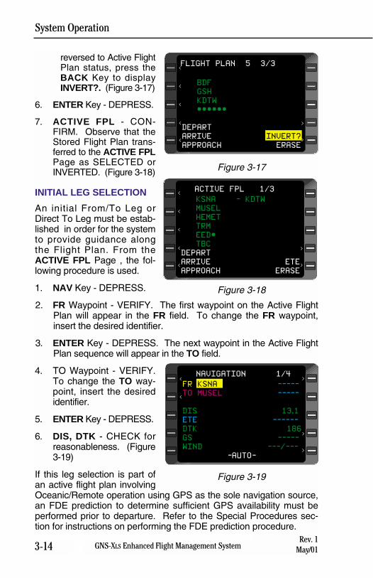
System Operation
3-14 GNS-XLS Enhanced Flight Management SystemRev. 1
May/01
reversed to Active FlightPlan status, press theBACK Key to displayINVERT?. (Figure 3-17)
6. ENTER Key - DEPRESS.
7. ACTIVE FPL - CON-FIRM. Observe that theStored Flight Plan trans-ferred to the ACTIVE FPLPage as SELECTED orINVERTED. (Figure 3-18)
INITIAL LEG SELECTION
An initial From/To Leg orDirect To Leg must be estab-lished in order for the systemto provide guidance alongthe Flight Plan. From theACTIVE FPL Page , the fol-lowing procedure is used.
1. NAV Key - DEPRESS.
2. FR Waypoint - VERIFY. The first waypoint on the Active FlightPlan will appear in the FR field. To change the FR waypoint,insert the desired identifier.
3. ENTER Key - DEPRESS. The next waypoint in the Active FlightPlan sequence will appear in the TO field.
4. TO Waypoint - VERIFY.To change the TO way-point, insert the desiredidentifier.
5. ENTER Key - DEPRESS.
6. DIS, DTK - CHECK forreasonableness. (Figure3-19)
If this leg selection is part ofan active flight plan involvingOceanic/Remote operation using GPS as the sole navigation source,an FDE prediction to determine sufficient GPS availability must beperformed prior to departure. Refer to the Special Procedures sec-tion for instructions on performing the FDE prediction procedure.
BDF
GSH
KDTW
******
DEPART
ARRIVE INVERT?
APPROACH ERASE
FLIGHT PLAN 5 3/3
><
<
<
<
<
>
Figure 3-17
KSNA - KDTW
MUSEL
HEMET
TRM
EED*
TBC
DEPART
ARRIVE ETE
APPROACH ERASE
ACTIVE FPL 1/3
><
<
<
<
<
>
Figure 3-18
FR KSNA -----
TO MUSEL -----
DIS 13.1
ETE ------
DTK 186
GS -----
WIND ---/---
-AUTO-
NAVIGATION 1/4
>
<
<
>
>
Figure 3-19
System Operation
3-15GNS-XLS Enhanced Flight Management SystemRev. 1May/01
BEFORE TAXI (IRS EQUIPPED)
The Inertial Reference System (IRS) should be aligned and placed inthe Navigation Mode using the IRS manufacturer’s operating instruc-tions.
1. MSG Key - DEPRESS for IRS Sensor Messages.
SENSOR MESSAGES Page will show IRS-ALIGN during align-ment sequence. When the IRS is in normal Navigation Mode noIRS messages will be displayed.
2. IRS Status - VERIFY NAV. Observe that no IRS messagesappear on the SENSOR MESSAGES Page.
RUNWAY LINE-UP (IRS EQUIPPED)Provided an accurate alignment position was entered and the IRS wasplaced in the Navigation Mode prior to taxi, no further action is required.
IRS, GPS AND/OR VPU EQUIPPED
On the ground the system will navigate deriving composite positionand groundspeed from the GPS or IRS, provided the IRS wasaligned and placed into the Navigation Mode prior to taxi. All othersensors (VPU) will enter the Primary Navigation Mode automaticallyat 50 kts (IRS) groundspeed or weight-off-wheels, provided they havesufficient stations to begin navigation. Momentarily depressingHOLD Key, then ENTER, and ENTER again will also put the sensorsin the primary NAV mode if sufficient stations are available.
VPU EQUIPPED ONLY
This procedure is used to manually place the system into the PrimaryNavigation Mode at the designated departure position i.e. the end ofthe departure runway. The VPU is a position finding sensor that cannavigate once airborne or within line of sight of suitable navaids.
1. MSG Key - DEPRESS.
2. MSG Key - DEPRESS to verify status of all sensors. ObserveNAV RDY/NO NAV messages for appropriate sensor and referto the Flight Manual Supplement for limitations.
3. HOLD Key - DEPRESS to verify departure coordinates.
4. ENTER Key - DEPRESS twice to enter Primary NavigationMode.
System Operation
3-16 GNS-XLS Enhanced Flight Management SystemRev. 3
Nov/04
NOTE: If the [HOLD/ENTER/ENTER] procedure had not been initi-ated prior to takeoff, the system and the various sensors will enter thePrimary Navigation Mode automatically at weight-off-wheels, or at atrue airspeed of between 50 and 150knots, depending on configura-tion.
SIDs, STARs, APPROACHES AND ENROUTE AIRWAYS
The GNS-XLS SID (Standard Instrument Departure), STAR (StandardTerminal Arrival), Approach and Airway retrieval feature is designedto relieve flight crew workload. SIDs and STARs require such proce-dures as flying headings and altitudes, as well as intercepting VORradials and DME arcs, etc. Approaches can be flown autopilot/fightdirector coupled until the Missed Approach Point. Missed ApproachProcedures must then be flown manually. The GNS-XLS is ONLYdesigned to provide meaningful input to the HSI when on a trackbetween two waypoints or when Pseudo Vortac (selected course)procedures are used. THE SYSTEM IS NOT DESIGNED TO FLYFULL SID, STAR OR MISSED APPROACH PROCEDURES.
NOTE: The flight crew must review the published procedure andcompare it to the procedure contained in the database. The pub-lished charts are the governing authority and the chart proceduresmust be followed. Any differences between the chart and the data-base must be resolved by the flight crew prior to commencing theprocedure.
When flying those portions of a SID or STAR that are not tracksbetween fixes, the aircraft should be flown manually or in HEADINGmode. In some cases, Pseudo Vortac procedures can be used toestablish an intercept to a published track. When using the PseudoVortac mode, or upon intercepting a published track between twowaypoints (fixes), the aircraft may be flown in reference to the crosstrack deviation provided by the GNS-XLS or by coupling the GNS-XLS
roll command to the auto pilot.
The first leg of the SID that the FMS can fly is not the first leg of theprocedure. To properly fly SIDs, the flight crew must manually fly theprocedure to a point where the FMS can fly the procedure properly.The first leg of the SID that the FMS can fly is usually the first way-point after the airport identifier or departure runway. After loading theSID on to the Active FPL, access NAV Pg 1. Enter the first waypointafter the runway or airport identifier in the FR field. Press ENTER.The TO field will display the next waypoint in sequence from the FPL.Press ENTER again to complete the initialization of the first leg of theflight plan. The flight crew must manually fly the airplane until reach-ing the first leg of the SID that can be flown by the FMS.
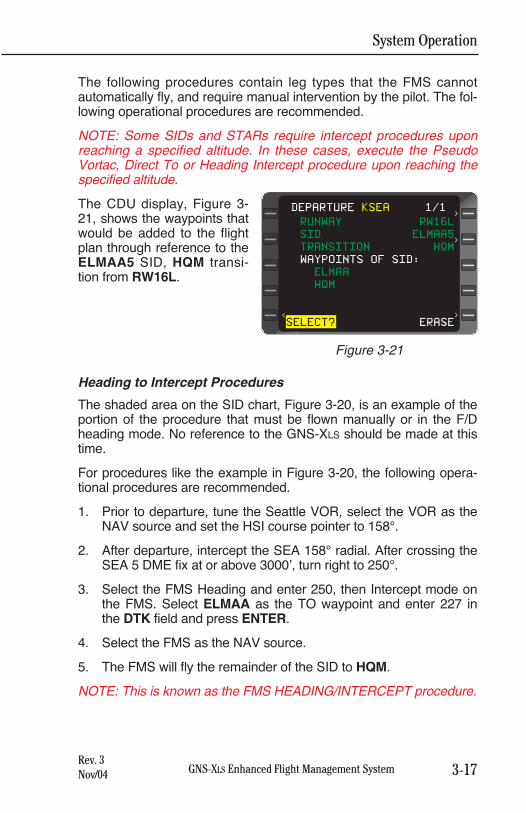
System Operation
3-17GNS-XLS Enhanced Flight Management SystemRev. 3Nov/04
The following procedures contain leg types that the FMS cannotautomatically fly, and require manual intervention by the pilot. The fol-lowing operational procedures are recommended.
NOTE: Some SIDs and STARs require intercept procedures uponreaching a specified altitude. In these cases, execute the PseudoVortac, Direct To or Heading Intercept procedure upon reaching thespecified altitude.
The CDU display, Figure 3-21, shows the waypoints thatwould be added to the flightplan through reference to theELMAA5 SID, HQM transi-tion from RW16L.
Heading to Intercept Procedures
The shaded area on the SID chart, Figure 3-20, is an example of theportion of the procedure that must be flown manually or in the F/Dheading mode. No reference to the GNS-XLS should be made at thistime.
For procedures like the example in Figure 3-20, the following opera-tional procedures are recommended.
1. Prior to departure, tune the Seattle VOR, select the VOR as theNAV source and set the HSI course pointer to 158°.
2. After departure, intercept the SEA 158° radial. After crossing theSEA 5 DME fix at or above 3000’, turn right to 250°.
3. Select the FMS Heading and enter 250, then Intercept mode onthe FMS. Select ELMAA as the TO waypoint and enter 227 inthe DTK field and press ENTER.
4. Select the FMS as the NAV source.
5. The FMS will fly the remainder of the SID to HQM.
NOTE: This is known as the FMS HEADING/INTERCEPT procedure.
RUNWAY RW16L
SID ELMAA5
TRANSITION HQM
WAYPOINTS OF SID:
ELMAA
HQM
SELECT? ERASE
DEPARTURE KSEA 1/1
><
>
>
Figure 3-21
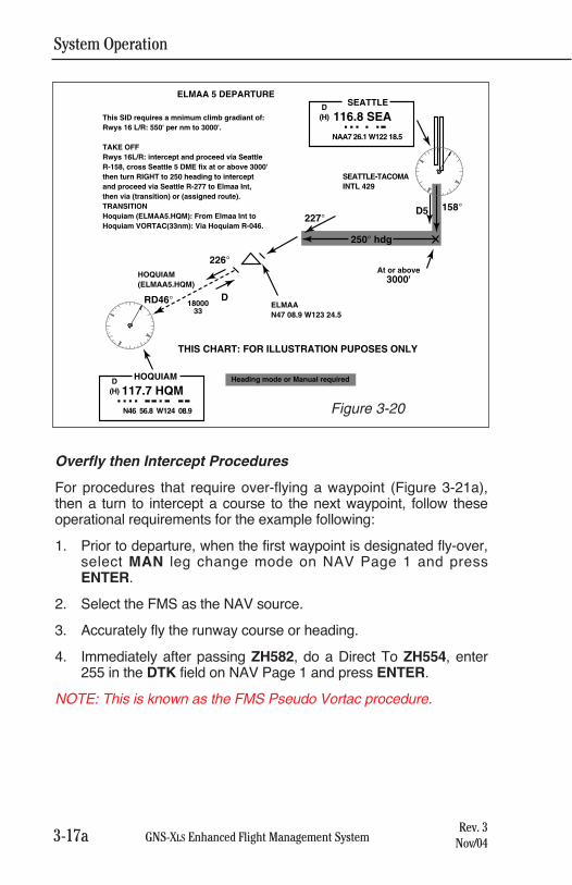
System Operation
GNS-XLS Enhanced Flight Management SystemRev. 3
Nov/04
Overfly then Intercept Procedures
For procedures that require over-flying a waypoint (Figure 3-21a),then a turn to intercept a course to the next waypoint, follow theseoperational requirements for the example following:
1. Prior to departure, when the first waypoint is designated fly-over,select MAN leg change mode on NAV Page 1 and pressENTER.
2. Select the FMS as the NAV source.
3. Accurately fly the runway course or heading.
4. Immediately after passing ZH582, do a Direct To ZH554, enter255 in the DTK field on NAV Page 1 and press ENTER.
NOTE: This is known as the FMS Pseudo Vortac procedure.
3-17a
250° hdg
227°
226°
DRD46° 1800033
HOQUIAM(ELMAA5.HQM)
SEATTLE-TACOMAINTL 429
ELMAAN47 08.9 W123 24.5
D5 158°
At or above3000'
SEATTLEELMAA 5 DEPARTURE
116.8 SEA
NAA7 26.1 W122 18.5
D(H)
HOQUIAM
117.7 HQM
N46 56.8 W124 08.9
D(H)
This SID requires a mnimum climb gradiant of: Rwys 16 L/R: 550' per nm to 3000'.
TAKE OFFRwys 16L/R: intercept and proceed via Seattle R-158, cross Seattle 5 DME fix at or above 3000' then turn RIGHT to 250 heading to intercept and proceed via Seattle R-277 to Elmaa Int, then via (transition) or (assigned route).TRANSITIONHoquiam (ELMAA5.HQM): From Elmaa Int to Hoquiam VORTAC(33nm): Via Hoquiam R-046.
THIS CHART: FOR ILLUSTRATION PUPOSES ONLY
Heading mode or Manual required
Figure 3-20
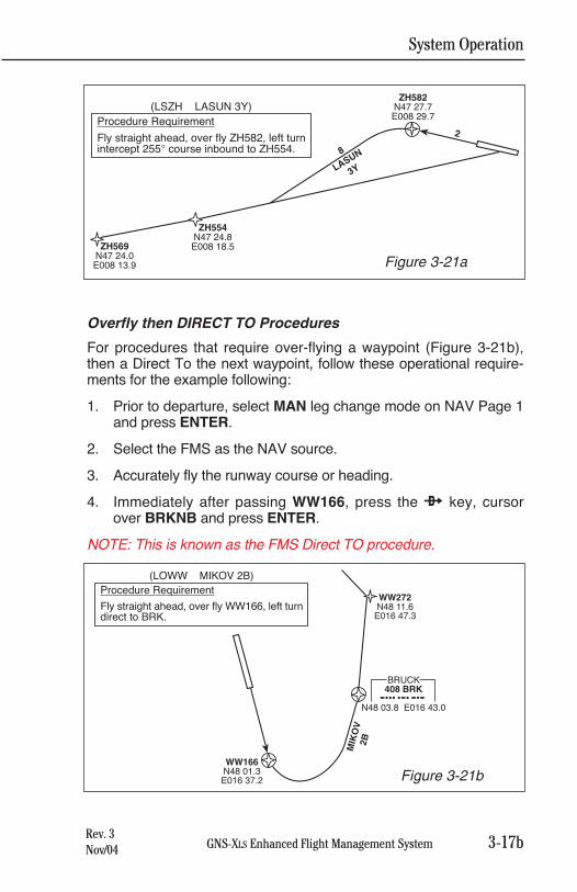
System Operation
GNS-XLS Enhanced Flight Management SystemRev. 3Nov/04
Overfly then DIRECT TO Procedures
For procedures that require over-flying a waypoint (Figure 3-21b),then a Direct To the next waypoint, follow these operational require-ments for the example following:
1. Prior to departure, select MAN leg change mode on NAV Page 1and press ENTER.
2. Select the FMS as the NAV source.
3. Accurately fly the runway course or heading.
4. Immediately after passing WW166, press the d key, cursorover BRKNB and press ENTER.
NOTE: This is known as the FMS Direct TO procedure.
WW166N48 01.3E016 37.2
MIK
OV
2B
WW272N48 11.6
E016 47.3
Procedure Requirement
Fly straight ahead, over fly WW166, left turndirect to BRK.
(LOWW MIKOV 2B)
BRUCK408 BRK
N48 03.8 E016 43.0
Figure 3-21b
ZH554N47 24.8E008 18.5
ZH582N47 27.7E008 29.7
2
8
LASUN
3Y
ZH569N47 24.0E008 13.9
Procedure Requirement
Fly straight ahead, over fly ZH582, left turnintercept 255° course inbound to ZH554.
(LSZH LASUN 3Y)
Figure 3-21a
3-17b
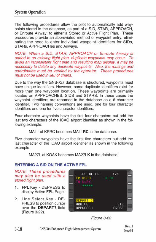
System Operation
3-18 GNS-XLS Enhanced Flight Management SystemRev. 3
Nov/04
The following procedures allow the pilot to automatically add way-points stored in the database, as part of a SID, STAR, APPROACH,or Enroute Airway, to either a Stored or Active Flight Plan. Theseprocedures provide an abbreviated method of waypoint entry, elimi-nating the need to enter individual waypoint identifiers for SIDs,STARs, APPROACHes and Airways.
NOTE: When a SID, STAR, APPROACH or Enroute Airway isadded to an existing flight plan, duplicate waypoints may occur. Toavoid an inconsistent flight plan and resulting map display, it may benecessary to delete any duplicate waypoints. Also, the routings andcoordinates must be verified by the operator. These proceduresmust not be used in lieu of charts.
Due to the way the GNS-XLS database is structured, waypoints musthave unique identifiers. However, some duplicate identifiers exist formore than one waypoint location. These waypoints are primarilylocated on APPROACHES, SIDS and STARS. In these cases thewaypoint identifiers are renamed in the database as a 6 characteridentifier. Two naming conventions are used, one for four characteridentifiers and one for five character identifiers.
Four character waypoints have the first four characters but add thelast two characters of the ICAO airport identifier as shown in the fol-lowing example:
MA11 at KPRC becomes MA11RC in the database.
Five character waypoints have the first five characters but add thelast character of the ICAO airport identifier as shown in the followingexample:
MA27L at KOAK becomes MA27LK in the database.
ENTERING A SID ON THE ACTIVE FPL
NOTE: These proceduresmay also be used with astored flight plan.
1. FPL Key - DEPRESS todisplay Active FPL Page.
2. Line Select Key - DE-PRESS to position cursorover the DEPART? field(Figure 3-22).
><
<
<
<
ACTIVE FPL 1/1
FR KSEA - KLAX
TO KLAX
*****
DEPART ?
ARRIVE ETE
APPROACH ERASE
Figure 3-22
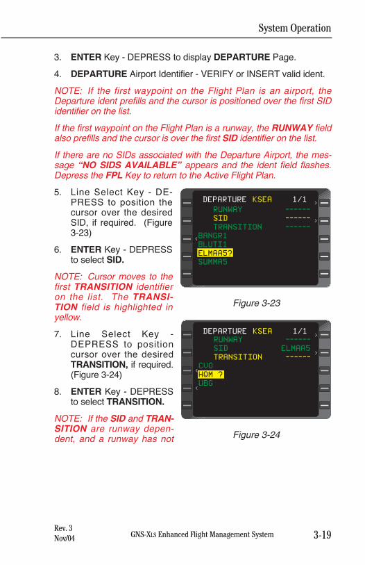
System Operation
3-19GNS-XLS Enhanced Flight Management SystemRev. 3Nov/04
3. ENTER Key - DEPRESS to display DEPARTURE Page.
4. DEPARTURE Airport Identifier - VERIFY or INSERT valid ident.
NOTE: If the first waypoint on the Flight Plan is an airport, theDeparture ident prefills and the cursor is positioned over the first SIDidentifier on the list.
If the first waypoint on the Flight Plan is a runway, the RUNWAY fieldalso prefills and the cursor is over the first SID identifier on the list.
If there are no SIDs associated with the Departure Airport, the mes-sage “NO SIDS AVAILABLE” appears and the ident field flashes.Depress the FPL Key to return to the Active Flight Plan.
5. Line Select Key - DE-PRESS to position thecursor over the desiredSID, if required. (Figure3-23)
6. ENTER Key - DEPRESSto select SID.
NOTE: Cursor moves to thefirst TRANSITION identifieron the list. The TRANSI-TION field is highlighted inyellow.
7. Line Select Key -DEPRESS to positioncursor over the desiredTRANSITION, if required.(Figure 3-24)
8. ENTER Key - DEPRESSto select TRANSITION.
NOTE: If the SID and TRAN-SITION are runway depen-dent, and a runway has not
<
RUNWAY ------
SID ------
TRANSITION ------
BANGR1
BLUTI1
ELMAA5?
SUMMA5
DEPARTURE KSEA 1/1>
>
Figure 3-23
<
RUNWAY ------
SID ELMAA5
TRANSITION ------
CVO
HQM ?
UBG
DEPARTURE KSEA 1/1>
>
<
Figure 3-24
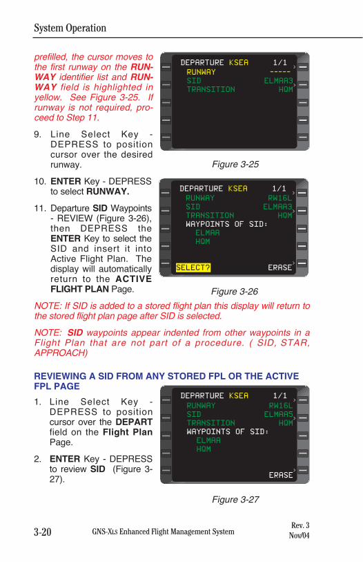
System Operation
3-20 GNS-XLS Enhanced Flight Management SystemRev. 3
Nov/04
prefilled, the cursor moves tothe first runway on the RUN-WAY identifier list and RUN-WAY field is highlighted inyellow. See Figure 3-25. Ifrunway is not required, pro-ceed to Step 11.
9. Line Select Key -DEPRESS to positioncursor over the desiredrunway.
10. ENTER Key - DEPRESSto select RUNWAY.
11. Departure SID Waypoints- REVIEW (Figure 3-26),then DEPRESS theENTER Key to select theSID and insert it intoActive Flight Plan. Thedisplay will automaticallyreturn to the ACTIVEFLIGHT PLAN Page.
NOTE: If SID is added to a stored flight plan this display will return tothe stored flight plan page after SID is selected.
NOTE: SID waypoints appear indented from other waypoints in aFlight Plan that are not part of a procedure. ( SID, STAR,APPROACH)
REVIEWING A SID FROM ANY STORED FPL OR THE ACTIVEFPL PAGE
1. Line Select Key -DEPRESS to positioncursor over the DEPARTfield on the Flight PlanPage.
2. ENTER Key - DEPRESSto review SID (Figure 3-27).
RUNWAY RW16L
SID ELMAA5
TRANSITION HQM
WAYPOINTS OF SID:
ELMAA
HQM
ERASE
DEPARTURE KSEA 1/1
>
>
>
Figure 3-27
RUNWAY -----
SID ELMAA3
TRANSITION HQM
DEPARTURE KSEA 1/1
>
>
Figure 3-25
RUNWAY RW16L
SID ELMAA3
TRANSITION HQM
WAYPOINTS OF SID:
ELMAA
HQM
SELECT? ERASE
DEPARTURE KSEA 1/1
>
>
>
Figure 3-26
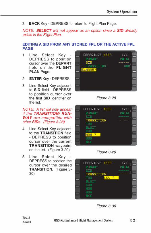
System Operation
3-21GNS-XLS Enhanced Flight Management SystemRev. 3Nov/04
3. BACK Key - DEPRESS to return to Flight Plan Page.
NOTE: SELECT will not appear as an option since a SID alreadyexists in the Flight Plan.
EDITING A SID FROM ANY STORED FPL OR THE ACTIVE FPLPAGE
1. Line Select Key -DEPRESS to positioncursor over the DEPARTfield on the FLIGHTPLAN Page.
2. ENTER Key - DEPRESS.
3. Line Select Key adjacentto SID field - DEPRESSto position cursor overthe first SID identifier onthe list.
NOTE: A list will only appearif the TRANSITION/ RUN-WAY are compatible withother SIDs. (Figure 3-28)
4. Line Select Key adjacentto the TRANSITION field- DEPRESS to positioncursor over the currentTRANSITION waypointon the list. (Figure 3-29)
5. Line Select Key -DEPRESS to position thecursor over the desiredTRANSITION. (Figure 3-30)
RUNWAY RW16L
SID ------
TRANSITION ------
TOU
BLUIT
CVO
HQM ?
UBG
BKE
DEPARTURE KSEA 1/1
>
>
Figure 3-29
RUNWAY RW16L
SID ------
TRANSITION ------
TOU LKV ?
BLUIT
CVO
HQM
UBG
BKE
DEPARTURE KSEA 1/1
>
>
Figure 3-30
RUNWAY RW16L
SID ------
TRANSITION HQM
ELMAA5?
DEPARTURE KSEA 1/1
>
>
Figure 3-28
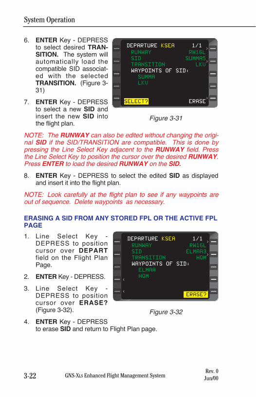
System Operation
3-22 GNS-XLS Enhanced Flight Management SystemRev. 0
Jun/00
6. ENTER Key - DEPRESSto select desired TRAN-SITION. The system willautomatically load thecompatible SID associat-ed with the selectedTRANSITION. (Figure 3-31)
7. ENTER Key - DEPRESSto select a new SID andinsert the new SID intothe flight plan.
NOTE: The RUNWAY can also be edited without changing the origi-nal SID if the SID/TRANSITION are compatible. This is done bypressing the Line Select Key adjacent to the RUNWAY field. Pressthe Line Select Key to position the cursor over the desired RUNWAY.Press ENTER to load the desired RUNWAY on the SID.
8. ENTER Key - DEPRESS to select the edited SID as displayedand insert it into the flight plan.
NOTE: Look carefully at the flight plan to see if any waypoints areout of sequence. Delete waypoints as necessary.
ERASING A SID FROM ANY STORED FPL OR THE ACTIVE FPLPAGE
1. Line Select Key -DEPRESS to positioncursor over DEPARTfield on the Flight PlanPage.
2. ENTER Key - DEPRESS.
3. Line Select Key -DEPRESS to positioncursor over ERASE?(Figure 3-32).
4. ENTER Key - DEPRESSto erase SID and return to Flight Plan page.
RUNWAY RW16L
SID ELMAA3
TRANSITION HQM
WAYPOINTS OF SID:
ELMAA
HQM
ERASE?
DEPARTURE KSEA 1/1
>
<
<
>
>
Figure 3-32
RUNWAY RW16L
SID SUMMA5
TRANSITION LKV
WAYPOINTS OF SID:
SUMMA
LKV
SELECT? ERASE
DEPARTURE KSEA 1/1
>
>
>
Figure 3-31
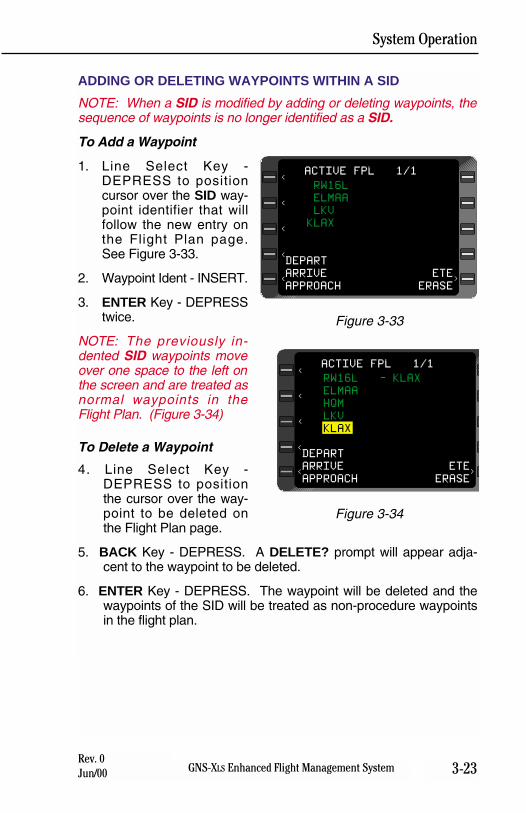
System Operation
3-23GNS-XLS Enhanced Flight Management SystemRev. 0Jun/00
ADDING OR DELETING WAYPOINTS WITHIN A SID
NOTE: When a SID is modified by adding or deleting waypoints, thesequence of waypoints is no longer identified as a SID.
To Add a Waypoint
1. Line Select Key -DEPRESS to positioncursor over the SID way-point identifier that willfollow the new entry onthe Flight Plan page.See Figure 3-33.
2. Waypoint Ident - INSERT.
3. ENTER Key - DEPRESStwice.
NOTE: The previously in-dented SID waypoints moveover one space to the left onthe screen and are treated asnormal waypoints in theFlight Plan. (Figure 3-34)
To Delete a Waypoint
4. Line Select Key -DEPRESS to positionthe cursor over the way-point to be deleted onthe Flight Plan page.
5. BACK Key - DEPRESS. A DELETE? prompt will appear adja-cent to the waypoint to be deleted.
6. ENTER Key - DEPRESS. The waypoint will be deleted and thewaypoints of the SID will be treated as non-procedure waypointsin the flight plan.
RW16L
ELMAA
LKV
KLAX
DEPART
ARRIVE ETE
APPROACH ERASE
ACTIVE FPL 1/1
<
<
<
<
<
>
Figure 3-33
RW16L - KLAX
ELMAA
HQM
LKV
KLAX
DEPART
ARRIVE ETE
APPROACH ERASE
ACTIVE FPL 1/1
>
<
<
<
<
<
Figure 3-34
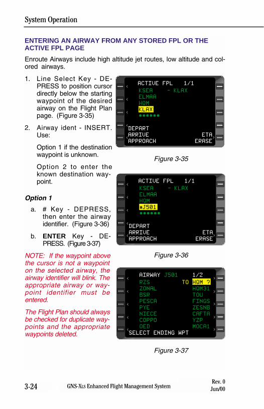
System Operation
3-24 GNS-XLS Enhanced Flight Management SystemRev. 0
Jun/00
ENTERING AN AIRWAY FROM ANY STORED FPL OR THEACTIVE FPL PAGE
Enroute Airways include high altitude jet routes, low altitude and col-ored airways.
1. Line Select Key - DE-PRESS to position cursordirectly below the startingwaypoint of the desiredairway on the Flight Planpage. (Figure 3-35)
2. Airway ident - INSERT.Use:
Option 1 if the destinationwaypoint is unknown.
Option 2 to enter theknown destination way-point.
Option 1
a. # Key - DEPRESS,then enter the airwayidentifier. (Figure 3-36)
b. ENTER Key - DE-PRESS. (Figure 3-37)
NOTE: If the waypoint abovethe cursor is not a waypointon the selected airway, theairway identifier will blink. Theappropriate airway or way-point identifier must beentered.
The Flight Plan should alwaysbe checked for duplicate way-points and the appropriatewaypoints deleted.
KSEA - KLAX
ELMAA
HQM
KLAX
******
DEPART
ARRIVE ETA
APPROACH ERASE
ACTIVE FPL 1/1
<
<
<
<
<
>
Figure 3-35
KSEA - KLAX
ELMAA
HQM
#J501
******
DEPART
ARRIVE ETA
APPROACH ERASE
ACTIVE FPL 1/1
<
<
<
<
<
>
Figure 3-36
RZS TO HQM ?
ZONAL HQM31
BSR TOU
PESCA FINGS
PYE ZESNB
NIECE CAFTA
COPPO YZP
OED MOCA1
SELECT ENDING WPT
AIRWAY J501 1/2
><
<
<
<
<
>
>
>
>
Figure 3-37
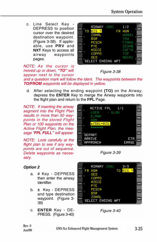
System Operation
3-25GNS-XLS Enhanced Flight Management SystemRev. 0Jun/00
c. Line Select Key -DEPRESS to positioncursor over the desireddestination waypoint.(Figure 3-38). If applic-able, use PRV andNXT Keys to access allairway waypointspages.
NOTE: As the cursor ismoved up or down, “TO” willappear next to the cursorand a question mark will follow the ident. The waypoints between theTO/FROM waypoints will be displayed in yellow.
d. After selecting the ending waypoint (TO) on the Airway,depress the ENTER Key to merge the Airway waypoints intothe flight plan and return to the FPL Page.
NOTE: If inserting the airwaysegment into the Flight Planresults in more than 50 way-points in the stored FlightPlan or 100 waypoints on theActive Flight Plan, the mes-sage “FPL FULL” will appear.
NOTE: Look carefully at theflight plan to see if any way-points are out of sequence.Delete waypoints as neces-sary.
Option 2
a. # Key - DEPRESSthen enter the airwayidentifier.
b. ± Key - DEPRESSand type destinationwaypoint. (Figure 3-39)
c. ENTER Key - DE-PRESS. (Figure 3-40)
TO RZS ? FR HQM
ZONAL HQM31
BSR TOU
PESCA FINGS
PYE ZESNB
NIECE CAFTA
COPPO YZP
OED MOCA1
SELECT ENDING WPT
AIRWAY J501 1/2
><
<
<
<
<
>
>
>
>
Figure 3-38
KSEA - KLAX
ELMAA
HQM
#J501+RZS
******
DEPART
ARRIVE ETA
APPROACH ERASE
ACTIVE FPL 1/1
<
<
<
<
<
>
Figure 3-39
FR HQM TO RZS ?
OED
COPPO
NIECE
PYE
PESCA
BSR
ZONAL
SELECT ENDING WPT
AIRWAY J501 3/3
<
<
<
< >
Figure 3-40
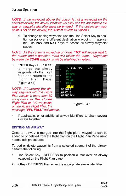
System Operation
3-26 GNS-XLS Enhanced Flight Management SystemRev. 0
Jun/00
NOTE: If the waypoint above the cursor is not a waypoint on theselected airway, the airway identifier will blink and the appropriate air-way or waypoint identifier must be entered. If the destination way-point is not on the airway, the system reverts to Option 1.
d. To change ending waypoint, use the Line Select Key to posi-tion cursor over a different destination waypoint. If applica-ble, use PRV and NXT Keys to access all airway waypointpages.
NOTE: As the cursor is moved up or down, “TO” will appear next tothe cursor and a question mark will follow the ident. Waypointsbetween the TO/FR waypoints will be displayed in yellow.
3. ENTER Key - DEPRESSto merge the airwaywaypoints into the FlightPlan and return to theFlight Plan Page.(Figure 3-41)
NOTE: If inserting the air-way segment into the FlightPlan results in more than 50waypoints in the storedFlight Plan or 100 waypointson the Active Flight Plan, themessage “FPL FULL” will appear.
4. If applicable, enter additional airway identifiers to chain severalairways together.
EDITING AN AIRWAY
Once an airway is merged into the flight plan, waypoints can beadded to or deleted from the flight plan on the Flight Plan Page usingnormal edit procedures.
To add or delete waypoints from a selected segment of the airway,perform the following:
1. Line Select Key - DEPRESS to position cursor over an airwaywaypoint on the Flight Plan page.
2. # Key - DEPRESS then enter the appropriate airway identifier.
RYE
PESCA
BSR
ZONAL
RZS
KLAX
DEPART
ARRIVE ETA
APPROACH ERASE
ACTIVE FPL 2/3
<
<
<
<
<
>
Figure 3-41
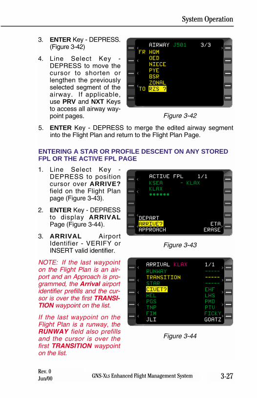
System Operation
3-27GNS-XLS Enhanced Flight Management SystemRev. 0Jun/00
3. ENTER Key - DEPRESS.(Figure 3-42)
4. Line Select Key -DEPRESS to move thecursor to shorten orlengthen the previouslyselected segment of theairway. If applicable,use PRV and NXT Keysto access all airway way-point pages.
5. ENTER Key - DEPRESS to merge the edited airway segmentinto the Flight Plan and return to the Flight Plan Page.
ENTERING A STAR OR PROFILE DESCENT ON ANY STOREDFPL OR THE ACTIVE FPL PAGE
1. Line Select Key -DEPRESS to positioncursor over ARRIVE?field on the Flight Planpage (Figure 3-43).
2. ENTER Key - DEPRESSto display ARRIVALPage (Figure 3-44).
3. ARRIVAL AirportIdentifier - VERIFY orINSERT valid identifier.
NOTE: If the last waypointon the Flight Plan is an air-port and an Approach is pro-grammed, the Arrival airportidentifier prefills and the cur-sor is over the first TRANSI-TION waypoint on the list.
If the last waypoint on theFlight Plan is a runway, theRUNWAY field also prefillsand the cursor is over thefirst TRANSITION waypointon the list.
FR HQM
OED
NIECE
PYE
BSR
ZONAL
TO RZS ?
AIRWAY J501 3/3
<
<
<
< >
Figure 3-42
KSEA - KLAX
KLAX
******
DEPART
ARRIVE? ETA
APPROACH ERASE
ACTIVE FPL 1/1
>
<
<
<
<
Figure 3-43
RUNWAY -----
TRANSITION -----
STAR -----
CIVET? EHF
HEL LHS
PGS PMD
TNP PTV
FIM FICKY
JLI GOATZ
ARRIVAL KLAX 1/1
><
<
<
<
<
>
>
>
>
Figure 3-44
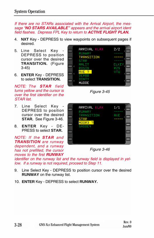
System Operation
3-28 GNS-XLS Enhanced Flight Management SystemRev. 0
Jun/00
If there are no STARs associated with the Arrival Airport, the mes-sage “NO STARS AVAILABLE” appears and the arrival airport identfield flashes. Depress FPL Key to return to ACTIVE FLIGHT PLAN.
4. NXT Key - DEPRESS to view waypoints on subsequent pages ifdesired.
5. Line Select Key -DEPRESS to positioncursor over the desiredTRANSITION. (Figure3-45)
6. ENTER Key - DEPRESSto select TRANSITION.
NOTE: The STAR fieldturns yellow and the cursor isover the first identifier on theSTAR list.
7. Line Select Key -DEPRESS to positioncursor over the desiredSTAR. See Figure 3-46.
8. ENTER Key - DE-PRESS to select STAR.
NOTE: If the STAR andTRANSITION are runwaydependent, and a runwayhas not prefilled, the cursormoves to the first RUNWAYidentifier on the runway list and the runway field is displayed in yel-low. If a runway is not required, proceed to Step 11.
9. Line Select Key - DEPRESS to position cursor over the desiredRUNWAY on the runway list.
10. ENTER Key - DEPRESS to select RUNWAY.
RUNWAY -----
TRANSITION -----
STAR -----
MALIT ELKEY
ROSIN RZS
AVE ? VTU
DERBB
DINTY
MUDDE
ARRIVAL KLAX 2/2
><
<
<
>
>
>
>
Figure 3-45
RUNWAY -----
TRANSITION AVE
STAR -----
MOOR3 ?
SADDE4
ARRIVAL KLAX 1/1>
>
Figure 3-46
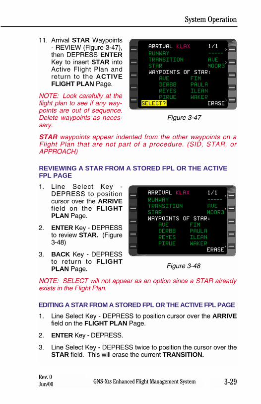
System Operation
3-29GNS-XLS Enhanced Flight Management SystemRev. 0Jun/00
11. Arrival STAR Waypoints- REVIEW (Figure 3-47),then DEPRESS ENTERKey to insert STAR intoActive Flight Plan andreturn to the ACTIVEFLIGHT PLAN Page.
NOTE: Look carefully at theflight plan to see if any way-points are out of sequence.Delete waypoints as neces-sary.
STAR waypoints appear indented from the other waypoints on aFlight Plan that are not part of a procedure. (SID, STAR, orAPPROACH)
REVIEWING A STAR FROM A STORED FPL OR THE ACTIVEFPL PAGE
1. Line Select Key -DEPRESS to positioncursor over the ARRIVEfield on the FLIGHTPLAN Page.
2. ENTER Key - DEPRESSto review STAR. (Figure3-48)
3. BACK Key - DEPRESSto return to FLIGHTPLAN Page.
NOTE: SELECT will not appear as an option since a STAR alreadyexists in the Flight Plan.
EDITING A STAR FROM A STORED FPL OR THE ACTIVE FPL PAGE
1. Line Select Key - DEPRESS to position cursor over the ARRIVEfield on the FLIGHT PLAN Page.
2. ENTER Key - DEPRESS.
3. Line Select Key - DEPRESS twice to position the cursor over theSTAR field. This will erase the current TRANSITION.
RUNWAY -----
TRANSITION AVE
STAR MOOR3
WAYPOINTS OF STAR:
AVE FIM
DERBB PAULA
REYES ILEAN
PIRUE WAKER
ERASE
ARRIVAL KLAX 1/1>
>
>
Figure 3-48
RUNWAY -----
TRANSITION AVE
STAR MOOR3
WAYPOINTS OF STAR:
AVE FIM
DERBB PAULA
REYES ILEAN
PIRUE WAKER
SELECT? ERASE
ARRIVAL KLAX 1/1>
>
>
Figure 3-47
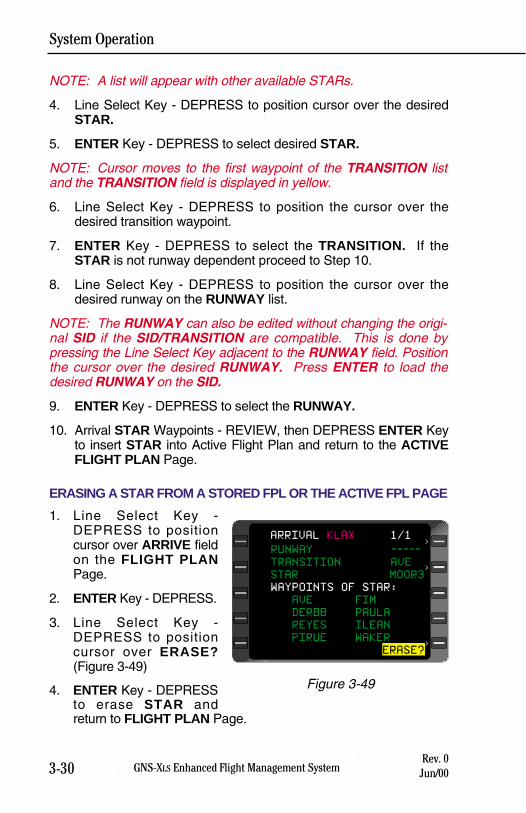
System Operation
3-30 GNS-XLS Enhanced Flight Management SystemRev. 0
Jun/00
NOTE: A list will appear with other available STARs.
4. Line Select Key - DEPRESS to position cursor over the desiredSTAR.
5. ENTER Key - DEPRESS to select desired STAR.
NOTE: Cursor moves to the first waypoint of the TRANSITION listand the TRANSITION field is displayed in yellow.
6. Line Select Key - DEPRESS to position the cursor over thedesired transition waypoint.
7. ENTER Key - DEPRESS to select the TRANSITION. If theSTAR is not runway dependent proceed to Step 10.
8. Line Select Key - DEPRESS to position the cursor over thedesired runway on the RUNWAY list.
NOTE: The RUNWAY can also be edited without changing the origi-nal SID if the SID/TRANSITION are compatible. This is done bypressing the Line Select Key adjacent to the RUNWAY field. Positionthe cursor over the desired RUNWAY. Press ENTER to load thedesired RUNWAY on the SID.
9. ENTER Key - DEPRESS to select the RUNWAY.
10. Arrival STAR Waypoints - REVIEW, then DEPRESS ENTER Keyto insert STAR into Active Flight Plan and return to the ACTIVEFLIGHT PLAN Page.
ERASING A STAR FROM A STORED FPL OR THE ACTIVE FPL PAGE
1. Line Select Key -DEPRESS to positioncursor over ARRIVE fieldon the FLIGHT PLANPage.
2. ENTER Key - DEPRESS.
3. Line Select Key -DEPRESS to positioncursor over ERASE?(Figure 3-49)
4. ENTER Key - DEPRESSto erase STAR andreturn to FLIGHT PLAN Page.
RUNWAY -----
TRANSITION AVE
STAR MOOR3
WAYPOINTS OF STAR:
AVE FIM
DERBB PAULA
REYES ILEAN
PIRUE WAKER
ERASE?
ARRIVAL KLAX 1/1>
>
>
Figure 3-49
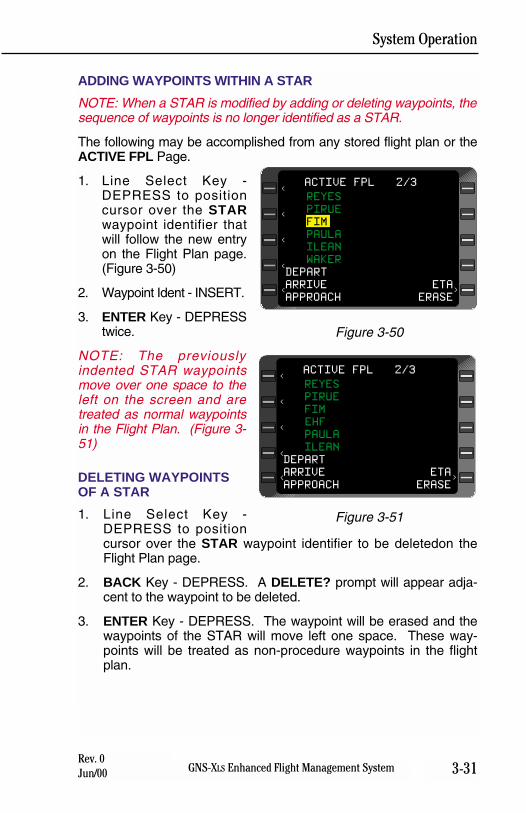
System Operation
3-31GNS-XLS Enhanced Flight Management SystemRev. 0Jun/00
ADDING WAYPOINTS WITHIN A STAR
NOTE: When a STAR is modified by adding or deleting waypoints, thesequence of waypoints is no longer identified as a STAR.
The following may be accomplished from any stored flight plan or theACTIVE FPL Page.
1. Line Select Key -DEPRESS to positioncursor over the STARwaypoint identifier thatwill follow the new entryon the Flight Plan page.(Figure 3-50)
2. Waypoint Ident - INSERT.
3. ENTER Key - DEPRESStwice.
NOTE: The previouslyindented STAR waypointsmove over one space to theleft on the screen and aretreated as normal waypointsin the Flight Plan. (Figure 3-51)
DELETING WAYPOINTSOF A STAR
1. Line Select Key -DEPRESS to positioncursor over the STAR waypoint identifier to be deletedon theFlight Plan page.
2. BACK Key - DEPRESS. A DELETE? prompt will appear adja-cent to the waypoint to be deleted.
3. ENTER Key - DEPRESS. The waypoint will be erased and thewaypoints of the STAR will move left one space. These way-points will be treated as non-procedure waypoints in the flightplan.
REYES
PIRUE
FIM
PAULA
ILEAN
WAKER
DEPART
ARRIVE ETA
APPROACH ERASE
ACTIVE FPL 2/3
<
<
<
<
<
>
Figure 3-50
REYES
PIRUE
FIM
EHF
PAULA
ILEAN
DEPART
ARRIVE ETA
APPROACH ERASE
ACTIVE FPL 2/3
<
<
<
<
<
>
Figure 3-51
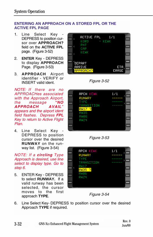
System Operation
3-32 GNS-XLS Enhanced Flight Management SystemRev. 0
Jun/00
ENTERING AN APPROACH ON A STORED FPL OR THEACTIVE FPL PAGE
1. Line Select Key -DEPRESS to position cur-sor over APPROACH?field on the ACTIVE FPLpage. (Figure 3-52)
2. ENTER Key - DEPRESSto display APPROACHPage. (Figure 3-53)
3. APPROACH Airportidentifier - VERIFY orINSERT valid ident.
NOTE: If there are noAPPROACHes associatedwith the Approach Airport,the message “NOAPPROACH AVAIL”appears and the airport identfield flashes. Depress FPLKey to return to Active FlightPlan.
4. Line Select Key -DEPRESS to positioncursor over the desiredRUNWAY on the run-way list. (Figure 3-54)
NOTE: If a circling TypeApproach is desired, use lineselect to display type. Go tostep 6.
5. ENTER Key - DEPRESSto select RUNWAY. If avalid runway has beenselected, the cursormoves to the firstapproach TYPE.
6. Line Select Key- DEPRESS to position cursor over the desiredApproach TYPE if required.
RUNWAY ------
TYPE ------
TRANSITION ------
RW17 ?
RW35
RW06
RW24
APCH KEWK 1/1>
>
Figure 3-53
KORD - KEWK
PNT
CAP
KEWK
DEPART
ARRIVE ETA
APPROACH? ERASE
ACTIVE FPL 1/1
<
<
<
<
<
>
Figure 3-52
RUNWAY ------
TYPE ------
TRANSITION ------
RW17
RW35 ?
RW06
RW24
APCH KEWK 1/1>
>
<
Figure 3-54
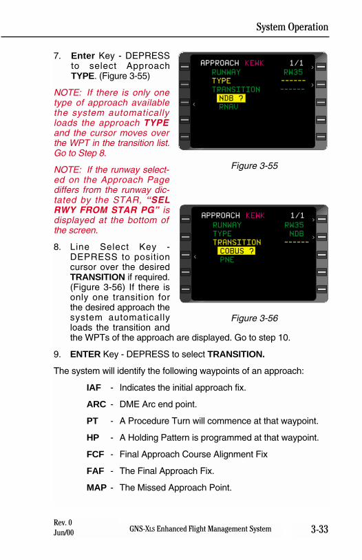
System Operation
3-33GNS-XLS Enhanced Flight Management SystemRev. 0Jun/00
7. Enter Key - DEPRESSto select ApproachTYPE. (Figure 3-55)
NOTE: If there is only onetype of approach availablethe system automaticallyloads the approach TYPEand the cursor moves overthe WPT in the transition list.Go to Step 8.
NOTE: If the runway select-ed on the Approach Pagediffers from the runway dic-tated by the STAR, “SELRWY FROM STAR PG” isdisplayed at the bottom ofthe screen.
8. Line Select Key -DEPRESS to positioncursor over the desiredTRANSITION if required.(Figure 3-56) If there isonly one transition forthe desired approach thesystem automaticallyloads the transition andthe WPTs of the approach are displayed. Go to step 10.
9. ENTER Key - DEPRESS to select TRANSITION.
The system will identify the following waypoints of an approach:
IAF - Indicates the initial approach fix.
ARC - DME Arc end point.
PT - A Procedure Turn will commence at that waypoint.
HP - A Holding Pattern is programmed at that waypoint.
FCF - Final Approach Course Alignment Fix
FAF - The Final Approach Fix.
MAP - The Missed Approach Point.
RUNWAY RW35
TYPE NDB
TRANSITION ------
COBUS ?
PNE
APPROACH KEWK 1/1>
>
<
Figure 3-56
RUNWAY RW35
TYPE ------
TRANSITION ------
NDB ?
RNAV
APPROACH KEWK 1/1>
>
<
Figure 3-55
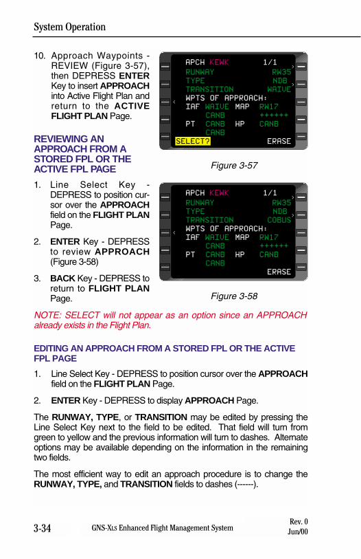
System Operation
3-34 GNS-XLS Enhanced Flight Management SystemRev. 0
Jun/00
10. Approach Waypoints -REVIEW (Figure 3-57),then DEPRESS ENTERKey to insert APPROACHinto Active Flight Plan andreturn to the ACTIVEFLIGHT PLAN Page.
REVIEWING ANAPPROACH FROM ASTORED FPL OR THEACTIVE FPL PAGE
1. Line Select Key -DEPRESS to position cur-sor over the APPROACHfield on the FLIGHT PLANPage.
2. ENTER Key - DEPRESSto review APPROACH(Figure 3-58)
3. BACK Key - DEPRESS toreturn to FLIGHT PLANPage.
NOTE: SELECT will not appear as an option since an APPROACHalready exists in the Flight Plan.
EDITING AN APPROACH FROM A STORED FPL OR THE ACTIVEFPL PAGE
1. Line Select Key - DEPRESS to position cursor over the APPROACHfield on the FLIGHT PLAN Page.
2. ENTER Key - DEPRESS to display APPROACH Page.
The RUNWAY, TYPE, or TRANSITION may be edited by pressing theLine Select Key next to the field to be edited. That field will turn fromgreen to yellow and the previous information will turn to dashes. Alternateoptions may be available depending on the information in the remainingtwo fields.
The most efficient way to edit an approach procedure is to change theRUNWAY, TYPE, and TRANSITION fields to dashes (------).
RUNWAY RW35
TYPE NDB
TRANSITION COBUS
WPTS OF APPROACH:
IAF WAIVE MAP RW17
CANB ++++++
PT CANB HP CANB
CANB
SELECT? ERASE
APCH KEWK 1/1>
>
<
Figure 3-58
RUNWAY RW35
TYPE NDB
TRANSITION WAIVE
WPTS OF APPROACH:
IAF WAIVE MAP RW17
CANB ++++++
PT CANB HP CANB
CANB
SELECT? ERASE
APCH KEWK 1/1>
>
<
Figure 3-57
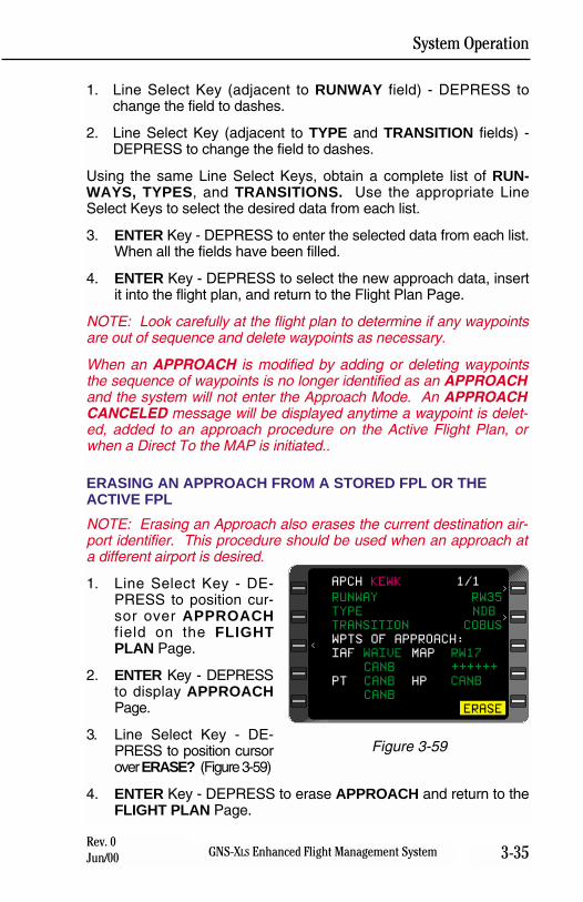
System Operation
3-35GNS-XLS Enhanced Flight Management SystemRev. 0Jun/00
1. Line Select Key (adjacent to RUNWAY field) - DEPRESS tochange the field to dashes.
2. Line Select Key (adjacent to TYPE and TRANSITION fields) -DEPRESS to change the field to dashes.
Using the same Line Select Keys, obtain a complete list of RUN-WAYS, TYPES, and TRANSITIONS. Use the appropriate LineSelect Keys to select the desired data from each list.
3. ENTER Key - DEPRESS to enter the selected data from each list.When all the fields have been filled.
4. ENTER Key - DEPRESS to select the new approach data, insertit into the flight plan, and return to the Flight Plan Page.
NOTE: Look carefully at the flight plan to determine if any waypointsare out of sequence and delete waypoints as necessary.
When an APPROACH is modified by adding or deleting waypointsthe sequence of waypoints is no longer identified as an APPROACHand the system will not enter the Approach Mode. An APPROACHCANCELED message will be displayed anytime a waypoint is delet-ed, added to an approach procedure on the Active Flight Plan, orwhen a Direct To the MAP is initiated..
ERASING AN APPROACH FROM A STORED FPL OR THEACTIVE FPL
NOTE: Erasing an Approach also erases the current destination air-port identifier. This procedure should be used when an approach ata different airport is desired.
1. Line Select Key - DE-PRESS to position cur-sor over APPROACHfield on the FLIGHTPLAN Page.
2. ENTER Key - DEPRESSto display APPROACHPage.
3. Line Select Key - DE-PRESS to position cursorover ERASE? (Figure 3-59)
4. ENTER Key - DEPRESS to erase APPROACH and return to theFLIGHT PLAN Page.
RUNWAY RW35
TYPE NDB
TRANSITION COBUS
WPTS OF APPROACH:
IAF WAIVE MAP RW17
CANB ++++++
PT CANB HP CANB
CANB
SELECT? ERASE
APCH KEWK 1/1>
>
<
Figure 3-59
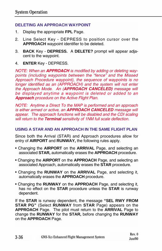
System Operation
3-36 GNS-XLS Enhanced Flight Management SystemRev. 0
Jun/00
DELETING AN APPROACH WAYPOINT
1. Display the appropriate FPL Page.
2. Line Select Key - DEPRESS to position cursor over theAPPROACH waypoint identifier to be deleted.
3. BACK Key - DEPRESS. A DELETE? prompt will appear adja-cent to the waypoint.
4. ENTER Key - DEPRESS.
NOTE: When an APPROACH is modified by adding or deleting way-points (including waypoints between the “fence” and the MissedApproach Procedure waypoint), the sequence of waypoints is nolonger identified as an (APPROACH) and the system will not enterthe Approach Mode. An (APPROACH CANCELED) message willbe displayed anytime a waypoint is deleted or added to anApproach procedure on the Active Flight Plan.
NOTE: Anytime a Direct To the MAP is performed and an approachis either armed or active, an APPROACH CANCELED message willappear. The approach functions will be disabled and the CDI scalingwill return to the Terminal sensitivity of 1NM full scale deflection.
USING A STAR AND AN APPROACH IN THE SAME FLIGHT PLAN
Since both the Arrival (STAR) and Approach procedures allow forentry of AIRPORT and RUNWAY, the following rules apply.
• Changing the AIRPORT on the ARRIVAL Page, and selecting anassociated STAR, automatically erases the APPROACH procedure.
• Changing the AIRPORT on the APPROACH Page, and selecting anassociated Approach, automatically erases the STAR procedure.
• Changing the RUNWAY on the ARRIVAL Page, and selecting it,automatically erases the APPROACH procedure.
• Changing the RUNWAY on the APPROACH Page, and selecting it,has no effect on the STAR procedure unless the STAR is runwaydependent.
If the STAR is runway dependent, the message “SEL RWY FROMSTAR PG” (Select RUNWAY from STAR Page) appears on theAPPROACH Page. The pilot must return to the ARRIVAL Page tochange the RUNWAY for the STAR, before changing the RUNWAYon the APPROACH Page.
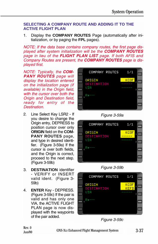
System Operation
3-37GNS-XLS Enhanced Flight Management SystemRev. 0Jun/00
SELECTING A COMPANY ROUTE AND ADDING IT TO THEACTIVE FLIGHT PLAN
1. Display the COMPANY ROUTES Page (automatically after ini-tialization, or by paging the FPL pages).
NOTE: If the data base contains company routes, the first page dis-played after system initialization will be the COMPANY ROUTESpage in lieu of the FLIGHT PLAN LIST page. If both AFIS andCompany Routes are present, the COMPANY ROUTES page is dis-played first.
NOTE: Typically, the COM-PANY ROUTES page willdisplay the location enteredon the initialization page (ifavailable) in the Origin field,with the cursor over both theOrigin and Destination field,ready for entry of theDestination.
2. Line Select Key LSR2 - Ifyou desire to change theOrigin entry, DEPRESS toposition cursor over onlyORIGIN field on the COM-PANY ROUTES page,and type in desired identi-fier. (Figure 3-59a) If thecursor is over both fields,and the Origin is correct,proceed to the next step.(Figure 3-59b)
3. DESTINATION identifier- VERIFY or INSERTvalid ident. (Figure 3-59b)
4. ENTER Key - DEPRESS.(Figure 3-59c) If the pair isvalid and has only oneVIA, the ACTIVE FLIGHTPLAN page is now dis-played with the waypointsof the pair added.
COMPANY ROUTES 1/1
<
>
>
ORIGIN KCOF
DESTINATION ------
VIA ------
R#---
Figure 3-59a
COMPANY ROUTES 1/1
<
>
>
ORIGIN KCOF
DESTINATION ------
VIA ------
R#---
Figure 3-59b
COMPANY ROUTES 1/1
<
>
>
ORIGIN KCOF
DESTINATION KEFD
VIA ------
R#---
Figure 3-59c
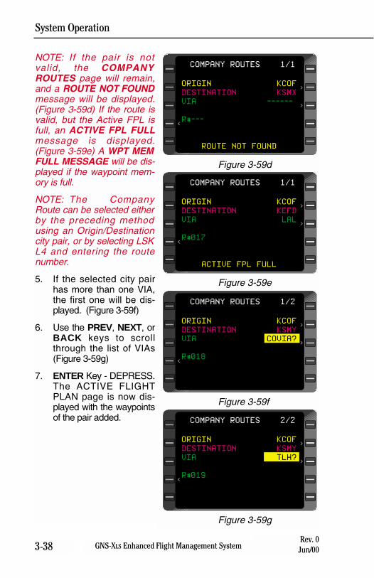
System Operation
3-38 GNS-XLS Enhanced Flight Management SystemRev. 0
Jun/00
NOTE: If the pair is notvalid, the COMPANYROUTES page will remain,and a ROUTE NOT FOUNDmessage will be displayed.(Figure 3-59d) If the route isvalid, but the Active FPL isfull, an ACTIVE FPL FULLmessage is displayed.(Figure 3-59e) A WPT MEMFULL MESSAGE will be dis-played if the waypoint mem-ory is full.
NOTE: The CompanyRoute can be selected eitherby the preceding methodusing an Origin/Destinationcity pair, or by selecting LSKL4 and entering the routenumber.
5. If the selected city pairhas more than one VIA,the first one will be dis-played. (Figure 3-59f)
6. Use the PREV, NEXT, orBACK keys to scrollthrough the list of VIAs(Figure 3-59g)
7. ENTER Key - DEPRESS.The ACTIVE FLIGHTPLAN page is now dis-played with the waypointsof the pair added.
COMPANY ROUTES 1/1
<
>
>
ORIGIN KCOF
DESTINATION KSMX
VIA ------
R#---
ROUTE NOT FOUND
Figure 3-59d
COMPANY ROUTES 1/1
<
>
>
ORIGIN KCOF
DESTINATION KEFD
VIA LAL
R#017
ACTIVE FPL FULL
Figure 3-59e
COMPANY ROUTES 1/2
<
>
>
ORIGIN KCOF
DESTINATION KSMY
VIA COVIA?
R#018
Figure 3-59f
COMPANY ROUTES 2/2
<
>
>
ORIGIN KCOF
DESTINATION KSMY
VIA TLH?
R#019
Figure 3-59g

System Operation
3-39GNS-XLS Enhanced Flight Management SystemRev. 0Jun/00
Note: In order to execute approaches with a specific aircraft installa-tion, the installation must meet the standards set forth by the govern-ing certification agency. Consult the Aircraft Flight ManualSupplement for specific limitations.
EXECUTING APPROACHESWarning: When entering PTs or HP airspace at high speed theFMS may not constrain the airplane from violating maneuveringairspace. Pilots are responsible for procedural compliance.
When the aircraft is within 30NM of the airport, the system will go intothe Approach Armed mode. The CDI sensitivity will change from5.0NM full scale deflection to 1.0NM full scale deflection. At this pointthe aircraft may bank slightly due to increased roll steering gains.Anytime the TO waypoint is part of an Approach Procedure, the SXTKfield is disabled so that no parallel course can be entered.
The system is capable of executing GPS, GPS Overlay, NDB, RNAV,CIRCLING, and VOR approaches only. No LOC, ILS or MLS capabili-ty is available.
If RAIM is not available at 2NM from the FAF, an APPROACH WARNmessage will appear on the SYSTEM MESSAGES Page. Also, theHSI flag will be set invalid. At this point the appropriate missedapproach procedures should be executed. The system will remain inthe Approach Mode and the discrete APPROACH annunciator willremain illuminated until the HSI is set valid. To set the HSI valid, can-cel the Approach on the SYSTEM MESSAGES Page by pressing theENTER Key.
The system will not display any interim waypoints between the FAFand the MAP, even though a waypoint may be shown on theapproach plate. The system may not give vertical guidance tothe interim waypoint. Pilots are responsible for procedural com-pliance.
NOTE: If the MAP is abeam or beyond the threshold, or the approachis a circling approach, no altitude constraints will be displayed at theMAP from the database. Constraints may be entered manually.
When the Approach is flown, the system will provide guidance alongthe final approach course to the Missed Approach Point.
When initially executing a missed approach procedure, use theFMS Heading Mode or manually fly the procedure to ensure prop-er track and turn direction.
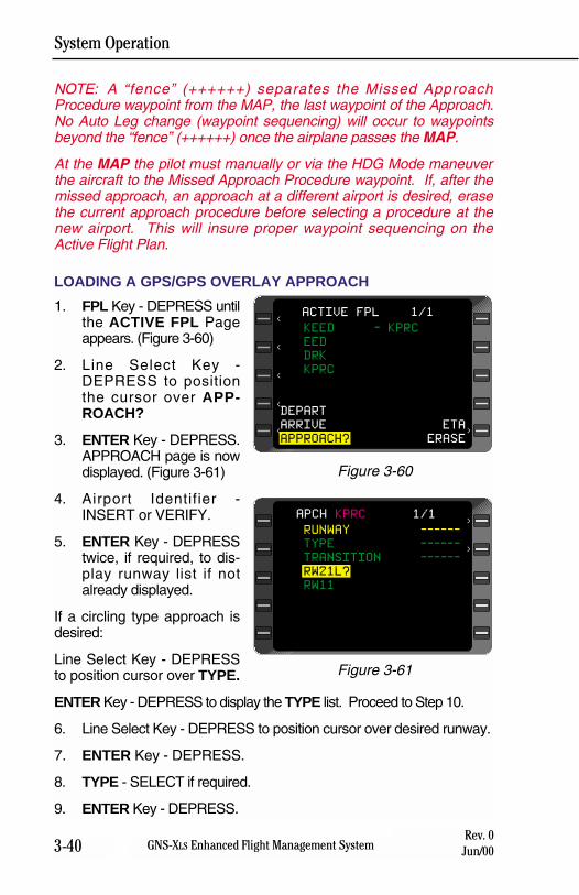
System Operation
3-40 GNS-XLS Enhanced Flight Management SystemRev. 0
Jun/00
NOTE: A “fence” (++++++) separates the Missed ApproachProcedure waypoint from the MAP, the last waypoint of the Approach.No Auto Leg change (waypoint sequencing) will occur to waypointsbeyond the “fence” (++++++) once the airplane passes the MAP.
At the MAP the pilot must manually or via the HDG Mode maneuverthe aircraft to the Missed Approach Procedure waypoint. If, after themissed approach, an approach at a different airport is desired, erasethe current approach procedure before selecting a procedure at thenew airport. This will insure proper waypoint sequencing on theActive Flight Plan.
LOADING A GPS/GPS OVERLAY APPROACH
1. FPL Key - DEPRESS untilthe ACTIVE FPL Pageappears. (Figure 3-60)
2. Line Select Key -DEPRESS to positionthe cursor over APP-ROACH?
3. ENTER Key - DEPRESS.APPROACH page is nowdisplayed. (Figure 3-61)
4. Airport Identifier -INSERT or VERIFY.
5. ENTER Key - DEPRESStwice, if required, to dis-play runway list if notalready displayed.
If a circling type approach isdesired:
Line Select Key - DEPRESSto position cursor over TYPE.
ENTER Key - DEPRESS to display the TYPE list. Proceed to Step 10.
6. Line Select Key - DEPRESS to position cursor over desired runway.
7. ENTER Key - DEPRESS.
8. TYPE - SELECT if required.
9. ENTER Key - DEPRESS.
RUNWAY ------
TYPE ------
TRANSITION ------
RW21L?
RW11
APCH KPRC 1/1
>
>
Figure 3-61
KEED - KPRC
EED
DRK
KPRC
DEPART
ARRIVE ETA
APPROACH? ERASE
ACTIVE FPL 1/1
<
<
<
<
<
>
Figure 3-60
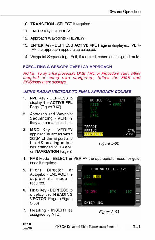
System Operation
3-41GNS-XLS Enhanced Flight Management SystemRev. 0Jun/00
10. TRANSITION - SELECT if required.
11. ENTER Key - DEPRESS.
12. Approach Waypoints - REVIEW.
13. ENTER Key - DEPRESS ACTIVE FPL Page is displayed. VER-IFY the approach appears as selected.
14. Waypoint Sequencing - Edit, if required, based on assigned route.
EXECUTING A GPS/GPS OVERLAY APPROACH
NOTE: To fly a full procedure DME ARC or Procedure Turn, eithercoupled or using own navigation, follow the FMS andEFIS/Instrument displays.
USING RADAR VECTORS TO FINAL APPROACH COURSE
1. FPL Key - DEPRESS todisplay the ACTIVE FPLPage. (Figure 3-62)
2. Approach and WaypointSequencing - VERIFYthey appear as selected.
3. MSG Key - VERIFYapproach is armed within30NM of the airport andthe HSI scaling outputhas changed to TRMNLon NAVIGATION Page 2.
4. FMS Mode - SELECT or VERIFY the appropriate mode for guid-ance if required.
5. Flight Director orAutopilot - ENGAGE theappropriate mode ifrequired.
6. HDG Key - DEPRESS todisplay the HEADINGVECTOR Page. (Figure3-63)
7. Heading - INSERT asassigned by ATC.
KEED - KPRC
EED
DRK
KPRC
DEPART
ARRIVE ETA
APPROACH? ERASE
ACTIVE FPL 1/1
<
<
<
<
<
>
Figure 3-62
HDG 155
CANCEL
TO DRK DTK 197
ENTER HDG
HEADING VECTOR 1/1
<
Figure 3-63
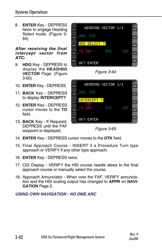
System Operation
3-42 GNS-XLS Enhanced Flight Management SystemRev. 0
Jun/00
8. ENTER Key - DEPRESStwice to engage HeadingSelect mode. (Figure 3-64)
After receiving the finalintercept vector fromATC:
9. HDG Key - DEPRESS todisplay the HEADINGVECTOR Page. (Figure3-65)
10. ENTER Key - DEPRESS.
11. BACK Key - DEPRESSto display INTERCEPT?
12. ENTER Key - DEPRESScursor moves to the TOfield.
13. BACK Key - If Required,DEPRESS until the FAFwaypoint is displayed.
14. ENTER Key - DEPRESS cursor moves to the DTK field.
15. Final Approach Course - INSERT if a Procedure Turn typeapproach or VERIFY if any other type approach.
16. ENTER Key - DEPRESS twice.
17. CDI Display - VERIFY the HSI course needle slews to the finalapproach course or manually select the course.
18. Approach Annunciator - When over the FAF, VERIFY annuncia-tion and the HSI scaling output has changed to APPR on NAVI-GATION Page 2.
USING OWN NAVIGATION - NO DME ARC
HDG 155
INTERCEPT ?
FAF
TO DRK DTK 197
OK? ENTER
HEADING VECTOR 1/1
>
<
<
<
Figure 3-65
HDG 155
HDG SELECT ?
TO DRK DTK 197
OK? ENTER
HEADING VECTOR 1/1
>
<
<
<
Figure 3-64
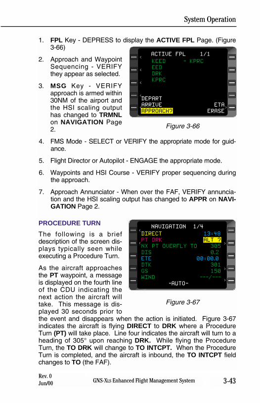
System Operation
3-43GNS-XLS Enhanced Flight Management SystemRev. 0Jun/00
1. FPL Key - DEPRESS to display the ACTIVE FPL Page. (Figure3-66)
2. Approach and WaypointSequencing - VERIFYthey appear as selected.
3. MSG Key - VERIFYapproach is armed within30NM of the airport andthe HSI scaling outputhas changed to TRMNLon NAVIGATION Page2.
4. FMS Mode - SELECT or VERIFY the appropriate mode for guid-ance.
5. Flight Director or Autopilot - ENGAGE the appropriate mode.
6. Waypoints and HSI Course - VERIFY proper sequencing duringthe approach.
7. Approach Annunciator - When over the FAF, VERIFY annuncia-tion and the HSI scaling output has changed to APPR on NAVI-GATION Page 2.
PROCEDURE TURN
The following is a briefdescription of the screen dis-plays typically seen whileexecuting a Procedure Turn.
As the aircraft approachesthe PT waypoint, a messageis displayed on the fourth lineof the CDU indicating thenext action the aircraft willtake. This message is dis-played 30 seconds prior tothe event and disappears when the action is initiated. Figure 3-67indicates the aircraft is flying DIRECT to DRK where a ProcedureTurn (PT) will take place. Line four indicates the aircraft will turn to aheading of 305° upon reaching DRK. While flying the ProcedureTurn, the TO DRK will change to TO INTCPT. When the ProcedureTurn is completed, and the aircraft is inbound, the TO INTCPT fieldchanges to TO (the FAF).
KEED - KPRC
EED
DRK
KPRC
DEPART
ARRIVE ETA
APPROACH? ERASE
ACTIVE FPL 1/1
<
<
<
<
<
>
Figure 3-66
DIRECT 13:48
PT DRK ALT ?
NX PT OVERFLY TO 305
DIS 0.2
ETE 00:00.0
DTK 301
GS 150
WIND ---/---
-AUTO-
NAVIGATION 1/4<
< >
>
>
Figure 3-67
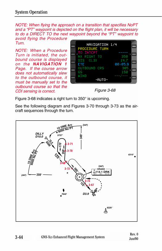
System Operation
3-44 GNS-XLS Enhanced Flight Management SystemRev. 0
Jun/00
NOTE: When flying the approach on a transition that specifies NoPTand a “PT” waypoint is depicted on the flight plan, it will be necessaryto do a DIRECT TO the next waypoint beyond the “PT” waypoint toavoid flying the ProcedureTurn.
NOTE: When a ProcedureTurn is initiated, the out-bound course is displayedon the NAVIGATION 1Page. If the course arrowdoes not automatically slewto the outbound course, itmust be manually set to theoutbound course so that theCDI sensing is correct.
Figure 3-68 indicates a right turn to 350° is upcoming.
See the following diagram and Figures 3-70 through 3-73 as the air-craft sequences through the turn.
259°
305°
650010.0
125°34
9°
350°
3-71
3-72
3-733-67
170°
125°
DILLYD10.0
114.1 DRK
D3.9
5757'
7640'
6310'
6220 '
(IAF)
(IAF)
10 DME Arc
9000 No PT
10D
ME
Arc
9000
No
PT
(IAF)DRAKE
D(H)
3-68
3-70
PROCEDURE TURN
TO INTCPT -----
NX RIGHT TO 350
DIS (1.3) 14.7
ETE 00:05.9
OUTBOUND CRS 305
GS 150
WIND ---/---
-AUTO-
NAVIGATION 1/4
<
>
>
>
Figure 3-68
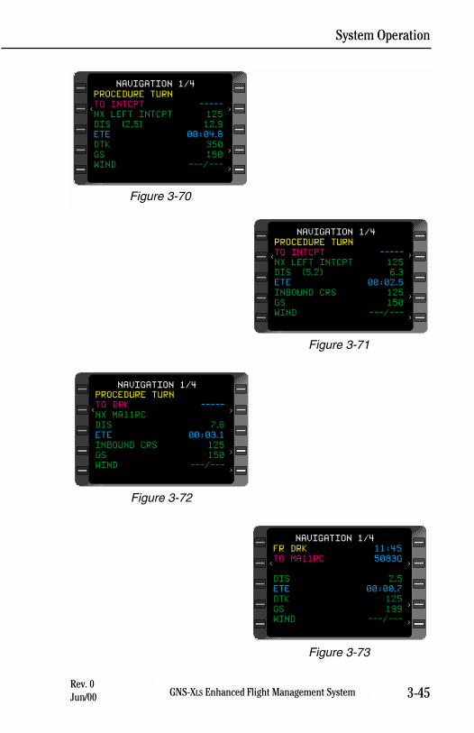
System Operation
3-45GNS-XLS Enhanced Flight Management SystemRev. 0Jun/00
Figure 3-70
PROCEDURE TURN
TO INTCPT -----
NX LEFT INTCPT 125
DIS (2.5) 12.9
ETE 00:04.8
DTK 350
GS 150
WIND ---/---
NAVIGATION 1/4
<
>
>
>
Figure 3-71
PROCEDURE TURN
TO INTCPT -----
NX LEFT INTCPT 125
DIS (5.2) 6.3
ETE 00:02.5
INBOUND CRS 125
GS 150
WIND ---/---
NAVIGATION 1/4
<
>
>
>
Figure 3-72
PROCEDURE TURN
TO DRK -----
NX MA11RC
DIS 7.8
ETE 00:03.1
INBOUND CRS 125
GS 150
WIND ---/---
NAVIGATION 1/4
<
>
>
>
Figure 3-73
FR DRK 11:45
TO MA11RC 5083G
DIS 2.5
ETE 00:00.7
DTK 125
GS 199
WIND ---/---
NAVIGATION 1/4
<
>
>
>
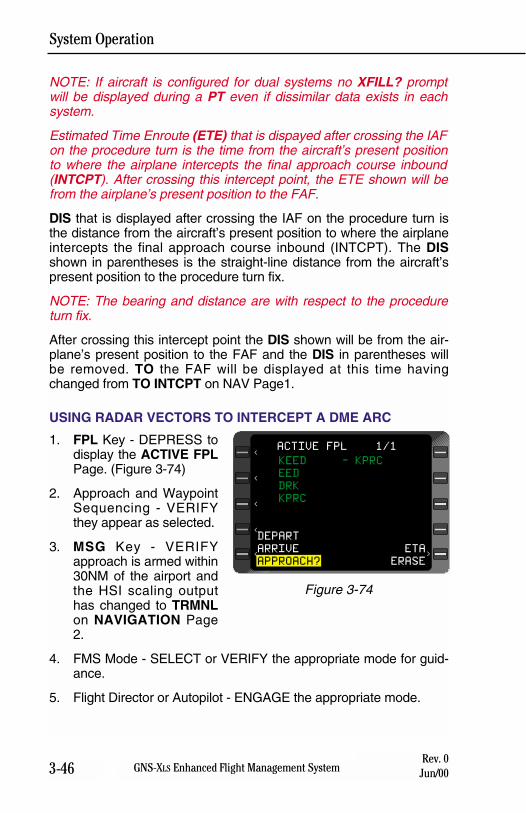
System Operation
3-46 GNS-XLS Enhanced Flight Management SystemRev. 0
Jun/00
NOTE: If aircraft is configured for dual systems no XFILL? promptwill be displayed during a PT even if dissimilar data exists in eachsystem.
Estimated Time Enroute (ETE) that is dispayed after crossing the IAFon the procedure turn is the time from the aircraft’s present positionto where the airplane intercepts the final approach course inbound(INTCPT). After crossing this intercept point, the ETE shown will befrom the airplane’s present position to the FAF.
DIS that is displayed after crossing the IAF on the procedure turn isthe distance from the aircraft’s present position to where the airplaneintercepts the final approach course inbound (INTCPT). The DISshown in parentheses is the straight-line distance from the aircraft’spresent position to the procedure turn fix.
NOTE: The bearing and distance are with respect to the procedureturn fix.
After crossing this intercept point the DIS shown will be from the air-plane’s present position to the FAF and the DIS in parentheses willbe removed. TO the FAF will be displayed at this time havingchanged from TO INTCPT on NAV Page1.
USING RADAR VECTORS TO INTERCEPT A DME ARC
1. FPL Key - DEPRESS todisplay the ACTIVE FPLPage. (Figure 3-74)
2. Approach and WaypointSequencing - VERIFYthey appear as selected.
3. MSG Key - VERIFYapproach is armed within30NM of the airport andthe HSI scaling outputhas changed to TRMNLon NAVIGATION Page2.
4. FMS Mode - SELECT or VERIFY the appropriate mode for guid-ance.
5. Flight Director or Autopilot - ENGAGE the appropriate mode.
KEED - KPRC
EED
DRK
KPRC
DEPART
ARRIVE ETA
APPROACH? ERASE
ACTIVE FPL 1/1
<
<
<
<
<
>
Figure 3-74
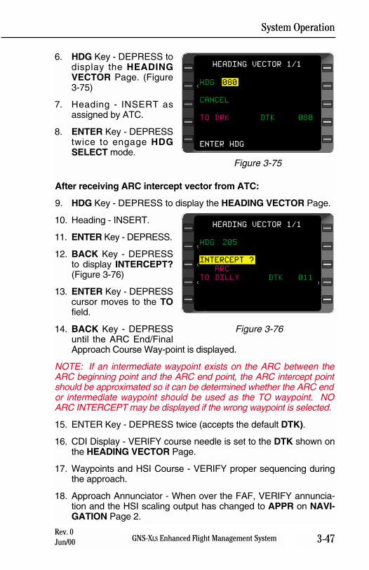
System Operation
3-47GNS-XLS Enhanced Flight Management SystemRev. 0Jun/00
6. HDG Key - DEPRESS todisplay the HEADINGVECTOR Page. (Figure3-75)
7. Heading - INSERT asassigned by ATC.
8. ENTER Key - DEPRESStwice to engage HDGSELECT mode.
After receiving ARC intercept vector from ATC:
9. HDG Key - DEPRESS to display the HEADING VECTOR Page.
10. Heading - INSERT.
11. ENTER Key - DEPRESS.
12. BACK Key - DEPRESSto display INTERCEPT?(Figure 3-76)
13. ENTER Key - DEPRESScursor moves to the TOfield.
14. BACK Key - DEPRESSuntil the ARC End/FinalApproach Course Way-point is displayed.
NOTE: If an intermediate waypoint exists on the ARC between theARC beginning point and the ARC end point, the ARC intercept pointshould be approximated so it can be determined whether the ARC endor intermediate waypoint should be used as the TO waypoint. NOARC INTERCEPT may be displayed if the wrong waypoint is selected.
15. ENTER Key - DEPRESS twice (accepts the default DTK).
16. CDI Display - VERIFY course needle is set to the DTK shown onthe HEADING VECTOR Page.
17. Waypoints and HSI Course - VERIFY proper sequencing duringthe approach.
18. Approach Annunciator - When over the FAF, VERIFY annuncia-tion and the HSI scaling output has changed to APPR on NAVI-GATION Page 2.
HDG 205
INTERCEPT ?
ARC
TO DILLY DTK 011
HEADING VECTOR 1/1
>
<
<
<
Figure 3-76
HDG 080
CANCEL
TO DRK DTK 080
ENTER HDG
HEADING VECTOR 1/1
<
Figure 3-75
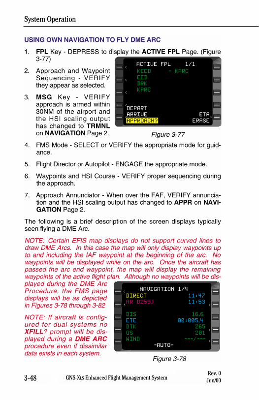
System Operation
3-48 GNS-XLS Enhanced Flight Management SystemRev. 0
Jun/00
USING OWN NAVIGATION TO FLY DME ARC
1. FPL Key - DEPRESS to display the ACTIVE FPL Page. (Figure3-77)
2. Approach and WaypointSequencing - VERIFYthey appear as selected.
3. MSG Key - VERIFYapproach is armed within30NM of the airport andthe HSI scaling outputhas changed to TRMNLon NAVIGATION Page 2.
4. FMS Mode - SELECT or VERIFY the appropriate mode for guid-ance.
5. Flight Director or Autopilot - ENGAGE the appropriate mode.
6. Waypoints and HSI Course - VERIFY proper sequencing duringthe approach.
7. Approach Annunciator - When over the FAF, VERIFY annuncia-tion and the HSI scaling output has changed to APPR on NAVI-GATION Page 2.
The following is a brief description of the screen displays typicallyseen flying a DME Arc.
NOTE: Certain EFIS map displays do not support curved lines todraw DME Arcs. In this case the map will only display waypoints upto and including the IAF waypoint at the beginning of the arc. Nowaypoints will be displayed while on the arc. Once the aircraft haspassed the arc end waypoint, the map will display the remainingwaypoints of the active flight plan. Although no waypoints will be dis-played during the DME ArcProcedure, the FMS pagedisplays will be as depictedin Figures 3-78 through 3-82
NOTE: If aircraft is config-ured for dual systems noXFILL? prompt will be dis-played during a DME ARCprocedure even if dissimilardata exists in each system.
DIRECT 11:47
AR D259J 11:53
DIS 16.6
ETE 00:005.4
DTK 265
GS 201
WIND ---/---
-AUTO-
NAVIGATION 1/4
<
>
>
>
<
Figure 3-78
KEED - KPRC
EED
DRK
KPRC
DEPART
ARRIVE ETA
APPROACH? ERASE
ACTIVE FPL 1/1
<
<
<
<
<
>
Figure 3-77
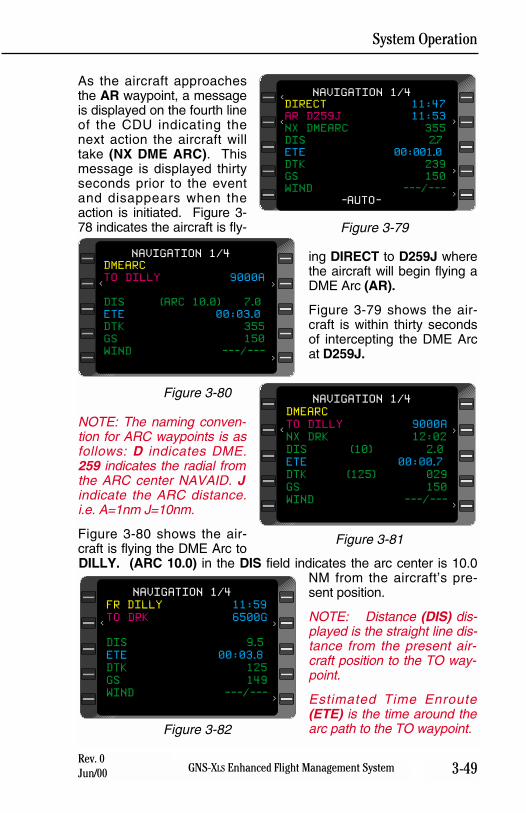
System Operation
3-49GNS-XLS Enhanced Flight Management SystemRev. 0Jun/00
As the aircraft approachesthe AR waypoint, a messageis displayed on the fourth lineof the CDU indicating thenext action the aircraft willtake (NX DME ARC). Thismessage is displayed thirtyseconds prior to the eventand disappears when theaction is initiated. Figure 3-78 indicates the aircraft is fly-
ing DIRECT to D259J wherethe aircraft will begin flying aDME Arc (AR).
Figure 3-79 shows the air-craft is within thirty secondsof intercepting the DME Arcat D259J.
NOTE: The naming conven-tion for ARC waypoints is asfollows: D indicates DME.259 indicates the radial fromthe ARC center NAVAID. Jindicate the ARC distance.i.e. A=1nm J=10nm.
Figure 3-80 shows the air-craft is flying the DME Arc toDILLY. (ARC 10.0) in the DIS field indicates the arc center is 10.0
NM from the aircraft’s pre-sent position.
NOTE: Distance (DIS) dis-played is the straight line dis-tance from the present air-craft position to the TO way-point.
Estimated Time Enroute(ETE) is the time around thearc path to the TO waypoint.
DIRECT 11:47
AR D259J 11:53
NX DMEARC 355
DIS 2.7
ETE 00:001.0
DTK 239
GS 150
WIND ---/---
-AUTO-
NAVIGATION 1/4
<
>
>
>
<
Figure 3-79
DMEARC
TO DILLY 9000A
DIS (ARC 10.0) 7.0
ETE 00:03.0
DTK 355
GS 150
WIND ---/---
NAVIGATION 1/4
<
>
>
Figure 3-80DMEARC
TO DILLY 9000A
NX DRK 12:02
DIS (10) 2.0
ETE 00:00.7
DTK (125) 029
GS 150
WIND ---/---
-AUTO-
NAVIGATION 1/4
<
>
>
Figure 3-81
FR DILLY 11:59
TO DRK 6500G
DIS 9.5
ETE 00:03.8
DTK 125
GS 149
WIND ---/---
NAVIGATION 1/4
<
>
>
Figure 3-82
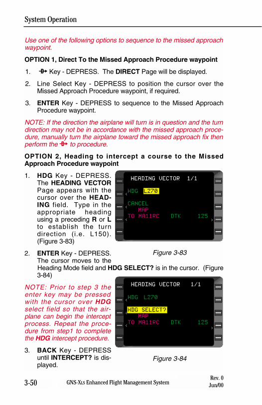
System Operation
3-50 GNS-XLS Enhanced Flight Management SystemRev. 0
Jun/00
Use one of the following options to sequence to the missed approachwaypoint.
OPTION 1, Direct To the Missed Approach Procedure waypoint
1. d Key - DEPRESS. The DIRECT Page will be displayed.
2. Line Select Key - DEPRESS to position the cursor over theMissed Approach Procedure waypoint, if required.
3. ENTER Key - DEPRESS to sequence to the Missed ApproachProcedure waypoint.
NOTE: If the direction the airplane will turn is in question and the turndirection may not be in accordance with the missed approach proce-dure, manually turn the airplane toward the missed approach fix thenperform the d to procedure.
OPTION 2, Heading to intercept a course to the MissedApproach Procedure waypoint
1. HDG Key - DEPRESS.The HEADING VECTORPage appears with thecursor over the HEAD-ING field. Type in theappropriate headingusing a preceding R or Lto establish the turndirection (i.e. L150).(Figure 3-83)
2. ENTER Key - DEPRESS.The cursor moves to theHeading Mode field and HDG SELECT? is in the cursor. (Figure3-84)
NOTE: Prior to step 3 theenter key may be pressedwith the cursor over HDGselect field so that the air-plane can begin the interceptprocess. Repeat the proce-dure from step1 to completethe HDG intercept procedure.
3. BACK Key - DEPRESSuntil INTERCEPT? is dis-played.
HDG L270
HDG SELECT?
MAP
TO MA11RC DTK 125
HEADING VECTOR 1/1
>
<
<
<
Figure 3-84
HDG L270
CANCEL
MAP
TO MA11RC DTK 125
HEADING VECTOR 1/1
>
<
<
<
Figure 3-83
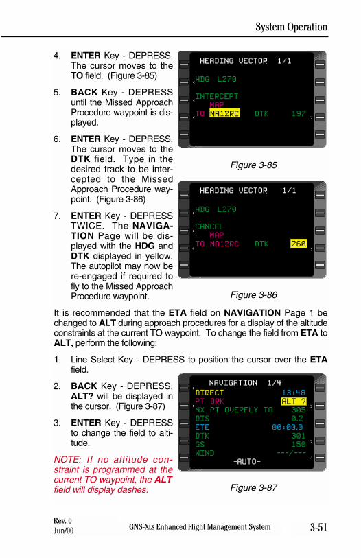
System Operation
3-51GNS-XLS Enhanced Flight Management SystemRev. 0Jun/00
4. ENTER Key - DEPRESS.The cursor moves to theTO field. (Figure 3-85)
5. BACK Key - DEPRESSuntil the Missed ApproachProcedure waypoint is dis-played.
6. ENTER Key - DEPRESS.The cursor moves to theDTK field. Type in thedesired track to be inter-cepted to the MissedApproach Procedure way-point. (Figure 3-86)
7. ENTER Key - DEPRESSTWICE. The NAVIGA-TION Page will be dis-played with the HDG andDTK displayed in yellow.The autopilot may now bere-engaged if required tofly to the Missed ApproachProcedure waypoint.
It is recommended that the ETA field on NAVIGATION Page 1 bechanged to ALT during approach procedures for a display of the altitudeconstraints at the current TO waypoint. To change the field from ETA toALT, perform the following:
1. Line Select Key - DEPRESS to position the cursor over the ETAfield.
2. BACK Key - DEPRESS.ALT? will be displayed inthe cursor. (Figure 3-87)
3. ENTER Key - DEPRESSto change the field to alti-tude.
NOTE: If no altitude con-straint is programmed at thecurrent TO waypoint, the ALTfield will display dashes.
HDG L270
INTERCEPT
MAP
TO MA12RC DTK 197
HEADING VECTOR 1/1
>
<
<
<
Figure 3-85
HDG L270
CANCEL
MAP
TO MA12RC DTK 260
HEADING VECTOR 1/1
>
<
<
<
Figure 3-86
DIRECT 13:48
PT DRK ALT ?
NX PT OVERFLY TO 305
DIS 0.2
ETE 00:00.0
DTK 301
GS 150
WIND ---/---
-AUTO-
NAVIGATION 1/4<
< >
>
>
Figure 3-87

System Operation
3-52 GNS-XLS Enhanced Flight Management SystemRev. 0
Jun/00
THIS PAGE INTENTIONALLY LEFT BLANK
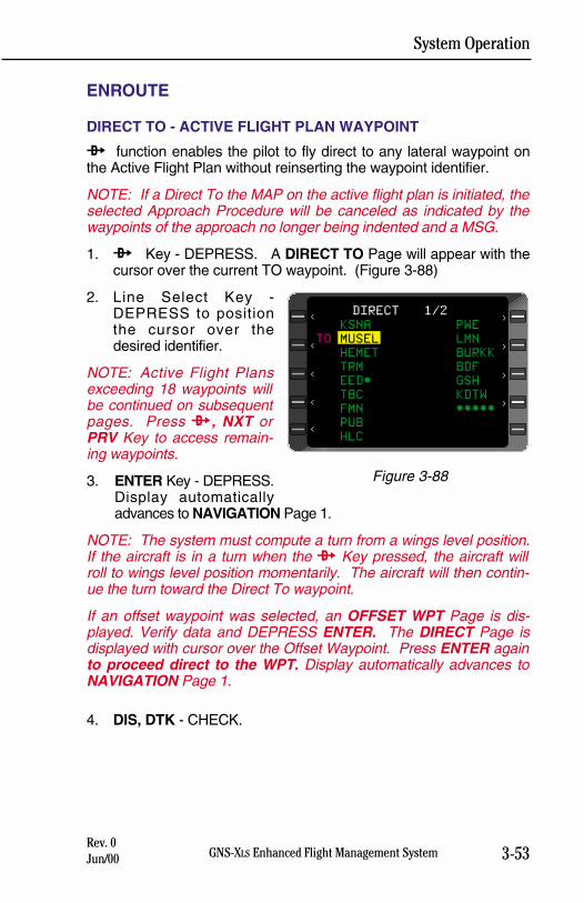
System Operation
3-53GNS-XLS Enhanced Flight Management SystemRev. 0Jun/00
ENROUTE
DIRECT TO - ACTIVE FLIGHT PLAN WAYPOINT
d function enables the pilot to fly direct to any lateral waypoint onthe Active Flight Plan without reinserting the waypoint identifier.
NOTE: If a Direct To the MAP on the active flight plan is initiated, theselected Approach Procedure will be canceled as indicated by thewaypoints of the approach no longer being indented and a MSG.
1. d Key - DEPRESS. A DIRECT TO Page will appear with thecursor over the current TO waypoint. (Figure 3-88)
2. Line Select Key -DEPRESS to positionthe cursor over thedesired identifier.
NOTE: Active Flight Plansexceeding 18 waypoints willbe continued on subsequentpages. Press d, NXT orPRV Key to access remain-ing waypoints.
3. ENTER Key - DEPRESS.Display automaticallyadvances to NAVIGATION Page 1.
NOTE: The system must compute a turn from a wings level position.If the aircraft is in a turn when the d Key pressed, the aircraft willroll to wings level position momentarily. The aircraft will then contin-ue the turn toward the Direct To waypoint.
If an offset waypoint was selected, an OFFSET WPT Page is dis-played. Verify data and DEPRESS ENTER. The DIRECT Page isdisplayed with cursor over the Offset Waypoint. Press ENTER againto proceed direct to the WPT. Display automatically advances toNAVIGATION Page 1.
4. DIS, DTK - CHECK.
KSNA PWE
TO MUSEL LMN
HEMET BURKK
TRM BDF
EED* GSH
TBC KDTW
FMN *****
PUB
HLC
DIRECT 1/2
>
>
>
>
<
<
<
<
<
Figure 3-88
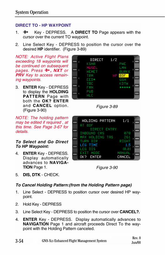
System Operation
3-54 GNS-XLS Enhanced Flight Management SystemRev. 0
Jun/00
DIRECT TO - HP WAYPOINT
1. d Key - DEPRESS. A DIRECT TO Page appears with thecursor over the current TO waypoint.
2. Line Select Key - DEPRESS to position the cursor over thedesired HP identifier. (Figure 3-89)
NOTE: Active Flight Plansexceeding 18 waypoints willbe continued on subsequentpages. Press d, NXT orPRV Key to access remain-ing waypoints.
3. ENTER Key - DEPRESSto display the HOLDINGPATTERN Page withboth the OK? ENTERand CANCEL option.(Figure 3-90)
NOTE: The holding patternmay be edited if required , atthis time. See Page 3-67 fordetails.
To Select and Go DirectTo HP Waypoint:
4. ENTER Key - DEPRESS.Display automaticallyadvances to NAVIGA-TION Page 1.
5. DIS, DTK - CHECK.
To Cancel Holding Pattern:(from the Holding Pattern page)
1. Line Select - DEPRESS to position cursor over desired HP way-point.
2. Hold Key - DEPRESS
3. Line Select Key - DEPRESS to position the cursor over CANCEL?.
4. ENTER Key - DEPRESS. Display automatically advances toNAVIGATION Page 1 and aircraft proceeds Direct To the way-point with the Holding Pattern canceled.
KSNA PWE
MUSEL LMN
HEMET BURKK
TRM HP BDF
EED* GSH
TBC KDTW
FMN *****
PUB
HLC
DIRECT 1/2
>
>
>
>
<
<
<
<
<
Figure 3-89
AT BDF
DIRECT ENTRY
INBOUND CRS 070
MAX HOLDING TAS 261
TURN DIR RIGHT
LEG TIME 1.5
LEG DIS (0.0)
EXIT MODE MANUAL
OK? ENTER CANCEL
HOLDING PATTERN 1/1
>
>
>
>
>
Figure 3-90
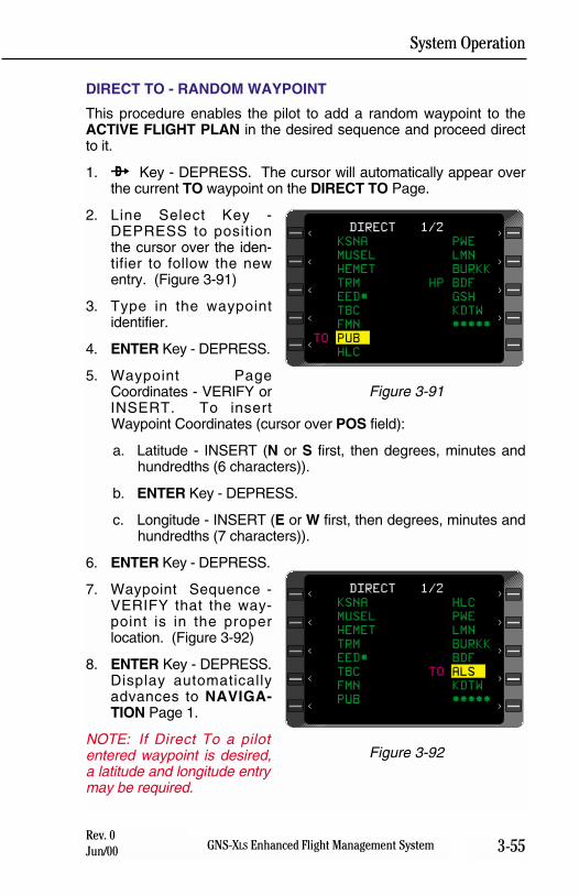
System Operation
3-55GNS-XLS Enhanced Flight Management SystemRev. 0Jun/00
DIRECT TO - RANDOM WAYPOINT
This procedure enables the pilot to add a random waypoint to theACTIVE FLIGHT PLAN in the desired sequence and proceed directto it.
1. d Key - DEPRESS. The cursor will automatically appear overthe current TO waypoint on the DIRECT TO Page.
2. Line Select Key -DEPRESS to positionthe cursor over the iden-tifier to follow the newentry. (Figure 3-91)
3. Type in the waypointidentifier.
4. ENTER Key - DEPRESS.
5. Waypoint PageCoordinates - VERIFY orINSERT. To insertWaypoint Coordinates (cursor over POS field):
a. Latitude - INSERT (N or S first, then degrees, minutes andhundredths (6 characters)).
b. ENTER Key - DEPRESS.
c. Longitude - INSERT (E or W first, then degrees, minutes andhundredths (7 characters)).
6. ENTER Key - DEPRESS.
7. Waypoint Sequence -VERIFY that the way-point is in the properlocation. (Figure 3-92)
8. ENTER Key - DEPRESS.Display automaticallyadvances to NAVIGA-TION Page 1.
NOTE: If Direct To a pilotentered waypoint is desired,a latitude and longitude entrymay be required.
KSNA PWE
MUSEL LMN
HEMET BURKK
TRM HP BDF
EED* GSH
TBC KDTW
FMN *****
TO PUB
HLC
DIRECT 1/2
>
>
>
>
<
<
<
<
<
Figure 3-91
KSNA HLC
MUSEL PWE
HEMET LMN
TRM BURKK
EED* BDF
TBC TO ALS
FMN KDTW
PUB *****
DIRECT 1/2
>
>
>
>
<
<
<
<
<
>
Figure 3-92
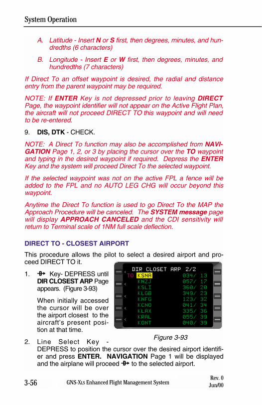
System Operation
3-56 GNS-XLS Enhanced Flight Management SystemRev. 0
Jun/00
A. Latitude - Insert N or S first, then degrees, minutes, and hun-dredths (6 characters)
B. Longitude - Insert E or W first, then degrees, minutes, andhundredths (7 characters)
If Direct To an offset waypoint is desired, the radial and distanceentry from the parent waypoint may be required.
NOTE: If ENTER Key is not depressed prior to leaving DIRECTPage, the waypoint identifier will not appear on the Active Flight Plan,the aircraft will not proceed DIRECT TO this waypoint and will needto be re-entered.
9. DIS, DTK - CHECK.
NOTE: A Direct To function may also be accomplished from NAVI-GATION Page 1, 2, or 3 by placing the cursor over the TO waypointand typing in the desired waypoint if required. Depress the ENTERKey and the system will proceed Direct To the selected waypoint.
If the selected waypoint was not on the active FPL a fence will beadded to the FPL and no AUTO LEG CHG will occur beyond thiswaypoint.
Anytime the Direct To function is used to go Direct To the MAP theApproach Procedure will be canceled. The SYSTEM message pagewill display APPROACH CANCELED and the CDI sensitivity willreturn to Terminal scale of 1NM full scale deflection.
DIRECT TO - CLOSEST AIRPORT
This procedure allows the pilot to select a desired airport and pro-ceed DIRECT TO it.
1. d Key- DEPRESS untilDIR CLOSEST ARP Pageappears. (Figure 3-93)
When initially accessedthe cursor will be overthe airport closest to theaircraft’s present posi-tion at that time.
2. Line Select Key -DEPRESS to position the cursor over the desired airport identifi-er and press ENTER. NAVIGATION Page 1 will be displayedand the airplane will proceed d to the selected airport.
TO KSNA 034/ 13
KNZJ 057/ 17
KSLI 360/ 20
KLGB 349/ 23
KNFG 123/ 32
KCNO 041/ 34
KLAX 335/ 36
KRAL 055/ 39
KONT 040/ 39
DIR CLOSET ARP 2/2
<
<
<
<
<
Figure 3-93
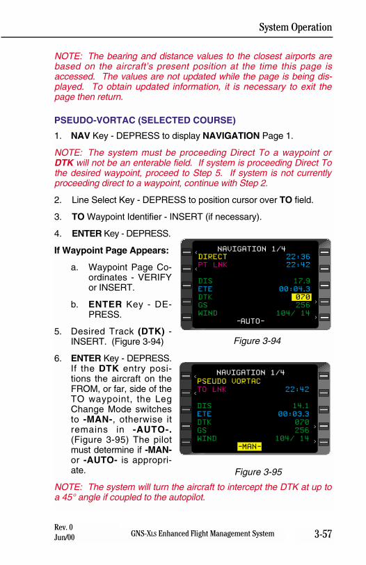
System Operation
3-57GNS-XLS Enhanced Flight Management SystemRev. 0Jun/00
NOTE: The bearing and distance values to the closest airports arebased on the aircraft’s present position at the time this page isaccessed. The values are not updated while the page is being dis-played. To obtain updated information, it is necessary to exit thepage then return.
PSEUDO-VORTAC (SELECTED COURSE)
1. NAV Key - DEPRESS to display NAVIGATION Page 1.
NOTE: The system must be proceeding Direct To a waypoint orDTK will not be an enterable field. If system is proceeding Direct Tothe desired waypoint, proceed to Step 5. If system is not currentlyproceeding direct to a waypoint, continue with Step 2.
2. Line Select Key - DEPRESS to position cursor over TO field.
3. TO Waypoint Identifier - INSERT (if necessary).
4. ENTER Key - DEPRESS.
If Waypoint Page Appears:
a. Waypoint Page Co-ordinates - VERIFYor INSERT.
b. ENTER Key - DE-PRESS.
5. Desired Track (DTK) -INSERT. (Figure 3-94)
6. ENTER Key - DEPRESS.If the DTK entry posi-tions the aircraft on theFROM, or far, side of theTO waypoint, the LegChange Mode switchesto -MAN-, otherwise itremains in -AUTO-.(Figure 3-95) The pilotmust determine if -MAN-or -AUTO- is appropri-ate.
NOTE: The system will turn the aircraft to intercept the DTK at up toa 45° angle if coupled to the autopilot.
DIRECT 22:36
PT LNK 22:42
DIS 17.9
ETE 00:04.3
DTK 070
GS 256
WIND 104/ 14
-AUTO-
NAVIGATION 1/4<
<
>
>
Figure 3-94
PSEUDO VORTAC
TO LNK 22:42
DIS 14.1
ETE 00:03.3
DTK 070
GS 256
WIND 104/ 14
-MAN-
NAVIGATION 1/4<
<
>
>
Figure 3-95
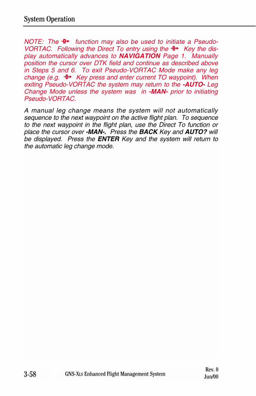
System Operation
3-58 GNS-XLS Enhanced Flight Management SystemRev. 0
Jun/00
NOTE: The d function may also be used to initiate a Pseudo-VORTAC. Following the Direct To entry using the d Key the dis-play automatically advances to NAVIGATION Page 1. Manuallyposition the cursor over DTK field and continue as described abovein Steps 5 and 6. To exit Pseudo-VORTAC Mode make any legchange (e.g. d Key press and enter current TO waypoint). Whenexiting Pseudo-VORTAC the system may return to the -AUTO- LegChange Mode unless the system was in -MAN- prior to initiatingPseudo-VORTAC.
A manual leg change means the system will not automaticallysequence to the next waypoint on the active flight plan. To sequenceto the next waypoint in the flight plan, use the Direct To function orplace the cursor over -MAN-. Press the BACK Key and AUTO? willbe displayed. Press the ENTER Key and the system will return tothe automatic leg change mode.
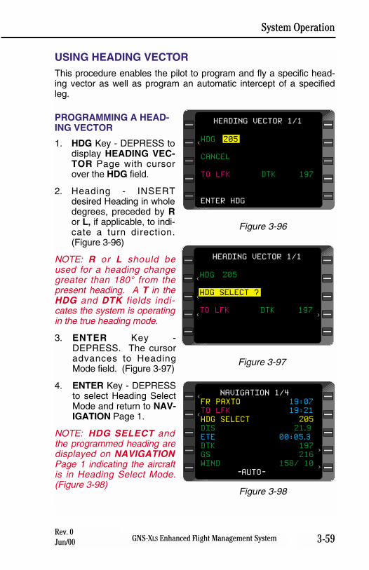
System Operation
3-59GNS-XLS Enhanced Flight Management SystemRev. 0Jun/00
USING HEADING VECTORThis procedure enables the pilot to program and fly a specific head-ing vector as well as program an automatic intercept of a specifiedleg.
PROGRAMMING A HEAD-ING VECTOR
1. HDG Key - DEPRESS todisplay HEADING VEC-TOR Page with cursorover the HDG field.
2. Heading - INSERTdesired Heading in wholedegrees, preceded by Ror L, if applicable, to indi-cate a turn direction.(Figure 3-96)
NOTE: R or L should beused for a heading changegreater than 180° from thepresent heading. A T in theHDG and DTK fields indi-cates the system is operatingin the true heading mode.
3. ENTER Key -DEPRESS. The cursoradvances to HeadingMode field. (Figure 3-97)
4. ENTER Key - DEPRESSto select Heading SelectMode and return to NAV-IGATION Page 1.
NOTE: HDG SELECT andthe programmed heading aredisplayed on NAVIGATIONPage 1 indicating the aircraftis in Heading Select Mode.(Figure 3-98)
FR PAXTO 19:07
TO LFK 19:21
HDG SELECT 205
DIS 21.9
ETE 00:05.3
DTK 197
GS 216
WIND 158/ 10
-AUTO-
NAVIGATION 1/4<
<
>
>
Figure 3-98
HDG 205
HDG SELECT ?
TO LFK DTK 197
HEADING VECTOR 1/1
>
<
<
<
Figure 3-97
HDG 205
CANCEL
TO LFK DTK 197
ENTER HDG
HEADING VECTOR 1/1
<
Figure 3-96
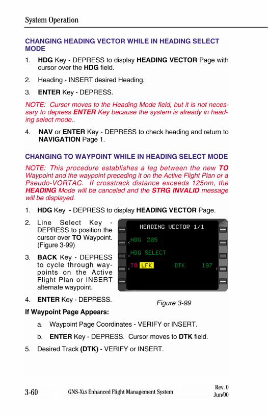
System Operation
3-60 GNS-XLS Enhanced Flight Management SystemRev. 0
Jun/00
CHANGING HEADING VECTOR WHILE IN HEADING SELECTMODE
1. HDG Key - DEPRESS to display HEADING VECTOR Page withcursor over the HDG field.
2. Heading - INSERT desired Heading.
3. ENTER Key - DEPRESS.
NOTE: Cursor moves to the Heading Mode field, but it is not neces-sary to depress ENTER Key because the system is already in head-ing select mode..
4. NAV or ENTER Key - DEPRESS to check heading and return toNAVIGATION Page 1.
CHANGING TO WAYPOINT WHILE IN HEADING SELECT MODE
NOTE: This procedure establishes a leg between the new TOWaypoint and the waypoint preceding it on the Active Flight Plan or aPseudo-VORTAC. If crosstrack distance exceeds 125nm, theHEADING Mode will be canceled and the STRG INVALID messagewill be displayed.
1. HDG Key - DEPRESS to display HEADING VECTOR Page.
2. Line Select Key -DEPRESS to position thecursor over TO Waypoint.(Figure 3-99)
3. BACK Key - DEPRESSto cycle through way-points on the ActiveFlight Plan or INSERTalternate waypoint.
4. ENTER Key - DEPRESS.
If Waypoint Page Appears:
a. Waypoint Page Coordinates - VERIFY or INSERT.
b. ENTER Key - DEPRESS. Cursor moves to DTK field.
5. Desired Track (DTK) - VERIFY or INSERT.
HDG 205
HDG SELECT
TO LFK DTK 197
HEADING VECTOR 1/1
>
<
<
<
Figure 3-99
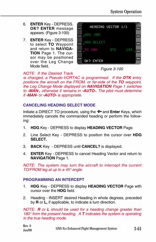
System Operation
3-61GNS-XLS Enhanced Flight Management SystemRev. 0Jun/00
6. ENTER Key - DEPRESS.OK? ENTER messageappears. (Figure 3-100)
7. ENTER Key - DEPRESSto select TO Waypointand return to NAVIGA-TION Page 1. The cur-sor may be positionedover the Leg ChangeMode field.
NOTE: If the Desired Trackis changed, a Pseudo-VORTAC is programmed. If the DTK entrypositions the aircraft on the FROM, or far-side of the TO waypoint,the Leg Change Mode displayed on NAVIGATION Page 1 switchesto -MAN-, otherwise it remains in -AUTO-. The pilot must determineif -MAN- or -AUTO- is appropriate.
CANCELING HEADING SELECT MODE
Initiate a DIRECT TO procedure, using the d and Enter Keys, whichimmediately cancels the commanded heading or perform the follow-ing:
1. HDG Key - DEPRESS to display HEADING VECTOR Page.
2. Line Select Key - DEPRESS to position the cursor over HDGSELECT.
3. BACK Key - DEPRESS until CANCEL? is displayed.
4. ENTER Key - DEPRESS to cancel Heading Vector and return toNAVIGATION Page 1.
NOTE: The system may turn the aircraft to intercept the currentTO/FROM leg at up to a 45° angle.
PROGRAMMING AN INTERCEPT
1. HDG Key - DEPRESS to display HEADING VECTOR Page withcursor over the HDG field.
2. Heading - INSERT desired Heading in whole degrees, precededby R or L, if applicable, to indicate a turn direction.
NOTE: R or L should be used for a heading change greater than180° from the present heading. A T indicates the system is operatingin the true heading mode.
HDG 205
HDG SELECT
TO IAH DTK 193
OK? ENTER
HEADING VECTOR 1/1
>
<
<
<
Figure 3-100
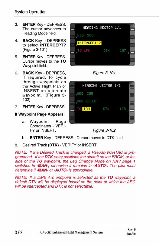
System Operation
3-62 GNS-XLS Enhanced Flight Management SystemRev. 0
Jun/00
3. ENTER Key - DEPRESS.The cursor advances toHeading Mode field.
4. BACK Key - DEPRESSto select INTERCEPT?(Figure 3-101)
5. ENTER Key - DEPRESS.Cursor moves to the TOWaypoint field.
6. BACK Key - DEPRESS,if required, to cyclethrough waypoints onthe Active Flight Plan orINSERT an alternatewaypoint. (Figure 3-102)
7. ENTER Key - DEPRESS.
If Waypoint Page Appears:
a. Waypoint PageCoordinates - VERI-FY or INSERT.
b. ENTER Key - DEPRESS. Cursor moves to DTK field.
8. Desired Track (DTK) - VERIFY or INSERT.
NOTE: If the Desired Track is changed, a Pseudo-VORTAC is pro-grammed. If the DTK entry positions the aircraft on the FROM, or far,side of the TO waypoint, the Leg Change Mode on NAV page 1switches to -MAN-, otherwise it remains in -AUTO-. The pilot mustdetermine if -MAN- or -AUTO- is appropriate.
NOTE: If a DME Arc endpoint is selected as the TO waypoint, adefault DTK will be displayed based on the point at which the ARCwill be intercepted and DTK is not selectable.
HDG 205
INTERCEPT ?
TO LFK DTK 197
HEADING VECTOR 1/1
>
<
<
<
Figure 3-101
HDG 205
HDG SELECT
TO IAH DTK 193
HEADING VECTOR 1/1
>
<
<
<
Figure 3-102
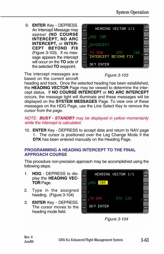
System Operation
3-63GNS-XLS Enhanced Flight Management SystemRev. 0Jun/00
9. ENTER Key - DEPRESS.An Intercept Message mayappear (NO COURSEINTERCEPT, NO ARCINTERCEPT, or INTER-CEPT BEYOND FIX(Figure 3-103). If no mes-sage appears the interceptwill occur on the TO side ofthe selected TO waypoint.
The intercept messages arebased on the current aircraftheading and track. Once the selected heading has been established,the HEADING VECTOR Page may be viewed to determine the inter-cept status. If NO COURSE INTERCEPT or NO ARC INTERCEPToccurs, the message light will illuminate and these messages will bedisplayed on the SYSTEM MESSAGES Page. To view one of thesemessages on the HDG Page, use the Line Select Key to remove thecursor from the page.
NOTE: BUSY - STANDBY may be displayed in yellow momentarilywhile the intercept is calculated.
10. ENTER Key - DEPRESS to accept data and return to NAV page1. The cursor is positioned over the Leg Change Mode if theDTK has been entered manually on the Heading Page.
PROGRAMMING A HEADING INTERCEPT TO THE FINALAPPROACH COURSE
This procedure non-precision approach may be accomplished using thefollowing steps:
1. HDG - DEPRESS to dis-play the HEADING VEC-TOR Page.
2. Type in the assignedheading. (Figure 3-104)
3. ENTER Key - DEPRESS.The cursor moves to theheading mode field.
HDG 205
TO DRK DTK 125
OK? ENTER
HEADING VECTOR 1/1
>
<
<
<
Figure 3-104
HDG 205
INTERCEPT
TO IAH DTK 193
INTERCEPT BEYOND FIX
OK? ENTER
HEADING VECTOR 1/1
>
<
<
<
Figure 3-103
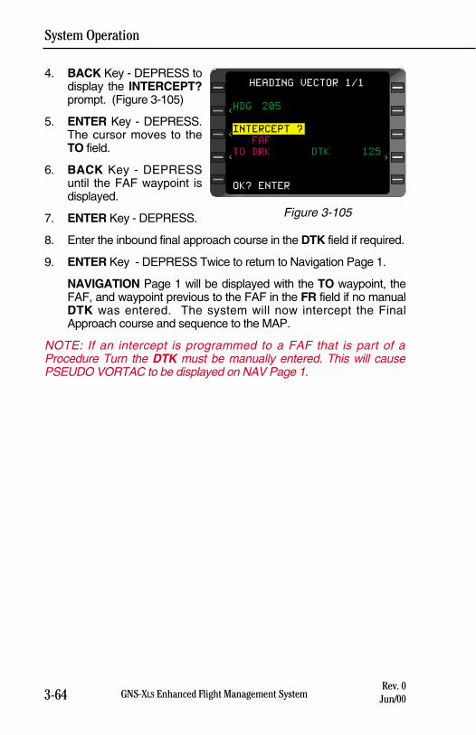
System Operation
3-64 GNS-XLS Enhanced Flight Management SystemRev. 0
Jun/00
4. BACK Key - DEPRESS todisplay the INTERCEPT?prompt. (Figure 3-105)
5. ENTER Key - DEPRESS.The cursor moves to theTO field.
6. BACK Key - DEPRESSuntil the FAF waypoint isdisplayed.
7. ENTER Key - DEPRESS.
8. Enter the inbound final approach course in the DTK field if required.
9. ENTER Key - DEPRESS Twice to return to Navigation Page 1.
NAVIGATION Page 1 will be displayed with the TO waypoint, theFAF, and waypoint previous to the FAF in the FR field if no manualDTK was entered. The system will now intercept the FinalApproach course and sequence to the MAP.
NOTE: If an intercept is programmed to a FAF that is part of aProcedure Turn the DTK must be manually entered. This will causePSEUDO VORTAC to be displayed on NAV Page 1.
HDG 205
INTERCEPT ?
FAF
TO DRK DTK 125
OK? ENTER
HEADING VECTOR 1/1
>
<
<
<
Figure 3-105
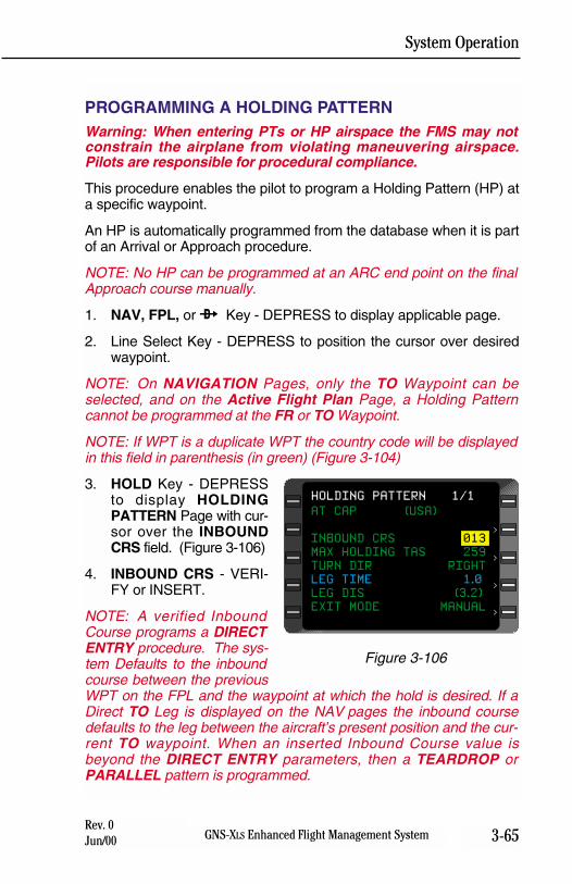
System Operation
3-65GNS-XLS Enhanced Flight Management SystemRev. 0Jun/00
PROGRAMMING A HOLDING PATTERNWarning: When entering PTs or HP airspace the FMS may notconstrain the airplane from violating maneuvering airspace.Pilots are responsible for procedural compliance.
This procedure enables the pilot to program a Holding Pattern (HP) ata specific waypoint.
An HP is automatically programmed from the database when it is partof an Arrival or Approach procedure.
NOTE: No HP can be programmed at an ARC end point on the finalApproach course manually.
1. NAV, FPL, or d Key - DEPRESS to display applicable page.
2. Line Select Key - DEPRESS to position the cursor over desiredwaypoint.
NOTE: On NAVIGATION Pages, only the TO Waypoint can beselected, and on the Active Flight Plan Page, a Holding Patterncannot be programmed at the FR or TO Waypoint.
NOTE: If WPT is a duplicate WPT the country code will be displayedin this field in parenthesis (in green) (Figure 3-104)
3. HOLD Key - DEPRESSto display HOLDINGPATTERN Page with cur-sor over the INBOUNDCRS field. (Figure 3-106)
4. INBOUND CRS - VERI-FY or INSERT.
NOTE: A verified InboundCourse programs a DIRECTENTRY procedure. The sys-tem Defaults to the inboundcourse between the previousWPT on the FPL and the waypoint at which the hold is desired. If aDirect TO Leg is displayed on the NAV pages the inbound coursedefaults to the leg between the aircraft’s present position and the cur-rent TO waypoint. When an inserted Inbound Course value isbeyond the DIRECT ENTRY parameters, then a TEARDROP orPARALLEL pattern is programmed.
AT CAP (USA)
INBOUND CRS 013
MAX HOLDING TAS 259
TURN DIR RIGHT
LEG TIME 1.0
LEG DIS (3.2)
EXIT MODE MANUAL
HOLDING PATTERN 1/1
>
>
>
>
Figure 3-106
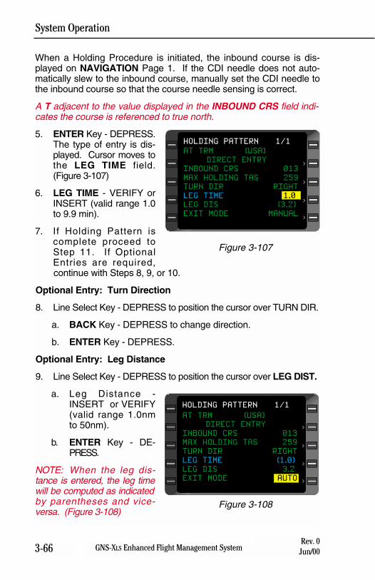
System Operation
3-66 GNS-XLS Enhanced Flight Management SystemRev. 0
Jun/00
When a Holding Procedure is initiated, the inbound course is dis-played on NAVIGATION Page 1. If the CDI needle does not auto-matically slew to the inbound course, manually set the CDI needle tothe inbound course so that the course needle sensing is correct.
A T adjacent to the value displayed in the INBOUND CRS field indi-cates the course is referenced to true north.
5. ENTER Key - DEPRESS.The type of entry is dis-played. Cursor moves tothe LEG TIME field.(Figure 3-107)
6. LEG TIME - VERIFY orINSERT (valid range 1.0to 9.9 min).
7. If Holding Pattern iscomplete proceed toStep 11. If OptionalEntries are required,continue with Steps 8, 9, or 10.
Optional Entry: Turn Direction
8. Line Select Key - DEPRESS to position the cursor over TURN DIR.
a. BACK Key - DEPRESS to change direction.
b. ENTER Key - DEPRESS.
Optional Entry: Leg Distance
9. Line Select Key - DEPRESS to position the cursor over LEG DIST.
a. Leg Distance -INSERT or VERIFY(valid range 1.0nmto 50nm).
b. ENTER Key - DE-PRESS.
NOTE: When the leg dis-tance is entered, the leg timewill be computed as indicatedby parentheses and vice-versa. (Figure 3-108)
AT TRM (USA)
DIRECT ENTRY
INBOUND CRS 013
MAX HOLDING TAS 259
TURN DIR RIGHT
LEG TIME 1.0
LEG DIS (3.2)
EXIT MODE MANUAL
HOLDING PATTERN 1/1
>
>
>
>
Figure 3-107
AT TRM (USA)
DIRECT ENTRY
INBOUND CRS 013
MAX HOLDING TAS 259
TURN DIR RIGHT
LEG TIME (1.0)
LEG DIS 3.2
EXIT MODE AUTO
HOLDING PATTERN 1/1
>
>
>
>
Figure 3-108
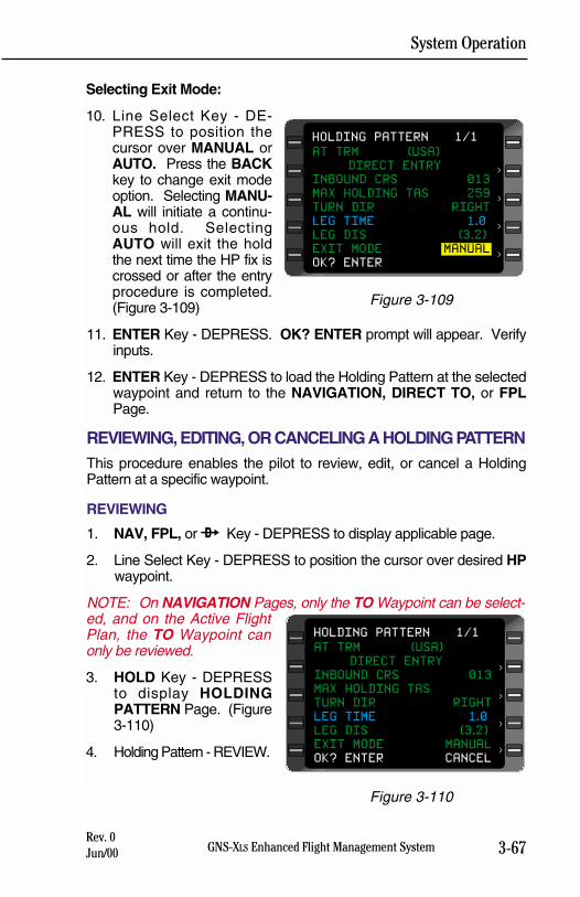
System Operation
3-67GNS-XLS Enhanced Flight Management SystemRev. 0Jun/00
Selecting Exit Mode:
10. Line Select Key - DE-PRESS to position thecursor over MANUAL orAUTO. Press the BACKkey to change exit modeoption. Selecting MANU-AL will initiate a continu-ous hold. SelectingAUTO will exit the holdthe next time the HP fix iscrossed or after the entryprocedure is completed.(Figure 3-109)
11. ENTER Key - DEPRESS. OK? ENTER prompt will appear. Verifyinputs.
12. ENTER Key - DEPRESS to load the Holding Pattern at the selectedwaypoint and return to the NAVIGATION, DIRECT TO, or FPLPage.
REVIEWING, EDITING, OR CANCELING A HOLDING PATTERNThis procedure enables the pilot to review, edit, or cancel a HoldingPattern at a specific waypoint.
REVIEWING
1. NAV, FPL, or d Key - DEPRESS to display applicable page.
2. Line Select Key - DEPRESS to position the cursor over desired HPwaypoint.
NOTE: On NAVIGATION Pages, only the TO Waypoint can be select-ed, and on the Active FlightPlan, the TO Waypoint canonly be reviewed.
3. HOLD Key - DEPRESSto display HOLDINGPATTERN Page. (Figure3-110)
4. Holding Pattern - REVIEW.
AT TRM (USA)
DIRECT ENTRY
INBOUND CRS 013
MAX HOLDING TAS 259
TURN DIR RIGHT
LEG TIME 1.0
LEG DIS (3.2)
EXIT MODE MANUAL
OK? ENTER
HOLDING PATTERN 1/1
>
>
>
>
Figure 3-109
AT TRM (USA)
DIRECT ENTRY
INBOUND CRS 013
MAX HOLDING TAS
TURN DIR RIGHT
LEG TIME 1.0
LEG DIS (3.2)
EXIT MODE MANUAL
OK? ENTER CANCEL
HOLDING PATTERN 1/1
>
>
>
>
Figure 3-110
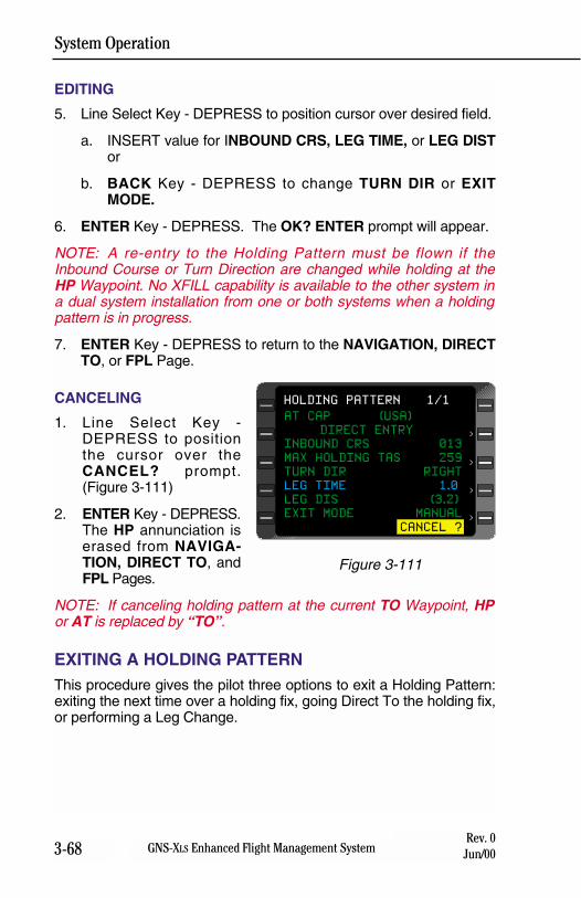
System Operation
3-68 GNS-XLS Enhanced Flight Management SystemRev. 0
Jun/00
EDITING
5. Line Select Key - DEPRESS to position cursor over desired field.
a. INSERT value for INBOUND CRS, LEG TIME, or LEG DISTor
b. BACK Key - DEPRESS to change TURN DIR or EXITMODE.
6. ENTER Key - DEPRESS. The OK? ENTER prompt will appear.
NOTE: A re-entry to the Holding Pattern must be flown if theInbound Course or Turn Direction are changed while holding at theHP Waypoint. No XFILL capability is available to the other system ina dual system installation from one or both systems when a holdingpattern is in progress.
7. ENTER Key - DEPRESS to return to the NAVIGATION, DIRECTTO, or FPL Page.
CANCELING
1. Line Select Key -DEPRESS to positionthe cursor over theCANCEL? prompt.(Figure 3-111)
2. ENTER Key - DEPRESS.The HP annunciation iserased from NAVIGA-TION, DIRECT TO, andFPL Pages.
NOTE: If canceling holding pattern at the current TO Waypoint, HPor AT is replaced by “TO”.
EXITING A HOLDING PATTERNThis procedure gives the pilot three options to exit a Holding Pattern:exiting the next time over a holding fix, going Direct To the holding fix,or performing a Leg Change.
AT CAP (USA)
DIRECT ENTRY
INBOUND CRS 013
MAX HOLDING TAS 259
TURN DIR RIGHT
LEG TIME 1.0
LEG DIS (3.2)
EXIT MODE MANUAL
CANCEL ?
HOLDING PATTERN 1/1
>
>
>
>
Figure 3-111
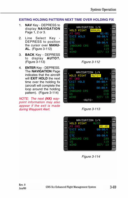
System Operation
3-69GNS-XLS Enhanced Flight Management SystemRev. 0Jun/00
EXITING HOLDING PATTERN NEXT TIME OVER HOLDING FIX
1. NAV Key - DEPRESS todisplay NAVIGATIONPage 1, 2 or 3.
2. Line Select Key -DEPRESS to positionthe cursor over MANU-AL. (Figure 3-112)
3. BACK Key - DEPRESSto display AUTO?.(Figure 3-113)
4. ENTER Key - DEPRESS.The NAVIGATION Pageindicates that the aircraftwill EXIT HOLD the nexttime over the holding fix(aircraft will complete theloop around the holdingpattern). (Figure 3-114)
NOTE: The next (NX) way-point information may alsoappear if the exit is madeduring Waypoint Alert.
HOLD RIGHT MANUAL
AT ORD 01:01
EXIT HOLD 00:00.4
DIS 1.4
ETE 00:00.4
INBOUND CRS 299
GS 119
WIND 327/ 13
NAVIGATION 1/4
<
>
>
<
Figure 3-112
HOLD RIGHT AUTO?
AT ORD 01:01
EXIT HOLD 00:00.4
DIS 1.4
ETE 00:00.4
INBOUND CRS 299
GS 119
WIND 327/ 13
-AUTO-
NAVIGATION 1/4
<
>
>
<
Figure 3-113
HOLD RIGHT AUTO
AT ORD 01:01
EXIT HOLD 00:00.4
DIS 1.4
ETE 00:00.4
INBOUND CRS 299
GS 119
WIND 327/ 13
NAVIGATION 1/4
<
>
>
<
Figure 3-114
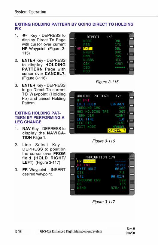
System Operation
3-70 GNS-XLS Enhanced Flight Management SystemRev. 0
Jun/00
EXITING HOLDING PATTERN BY GOING DIRECT TO HOLDINGFIX
1. d Key - DEPRESS todisplay Direct To Pagewith cursor over currentHP Waypoint. (Figure 3-115)
2. ENTER Key - DEPRESSto display HOLDINGPATTERN Page withcursor over CANCEL?.(Figure 3-116)
3. ENTER Key - DEPRESSto go Direct To currentTO Waypoint (HoldingFix) and cancel HoldingPattern.
EXITING HOLDING PAT-TERN BY PERFORMING ALEG CHANGE
1. NAV Key - DEPRESS todisplay the NAVIGA-TION Page 1.
2. Line Select Key -DEPRESS to positionthe cursor over FROMfield (HOLD RIGHT/LEFT). (Figure 3-117)
3. FR Waypoint - INSERTdesired waypoint.
AT FNT
EXIT HOLD 00:00.4
INBOUND CRS 299
MAX HOLDING TAS 305
TURN DIR RIGHT
LEG TIME 1.0
LEG DIS (3.5)
EXIT MODE MANUAL
CANCEL ?
HOLDING PATTERN 1/1
>
>
>
>
Figure 3-116
FR ------ ------
AT FNT 15:22
EXIT HOLD 00:02
DIS 7.3
ETE 00:02.4
INBOUND CRS 299
GS 175
WIND 375/ 13
NAVIGATION 1/4
<
>
>
<
Figure 3-117
KABE ONL
PSB CYS
HP FNT DBL
HASTE DVC
PMM PGS
KUBBS HEC
OBK KVNY
DBQ *****
FOD
DIRECT 1/2
>
>
>
>
<
<
<
<
<
>
Figure 3-115
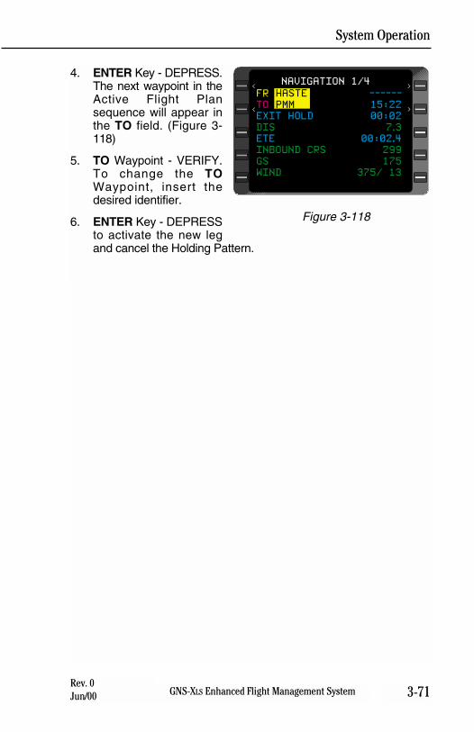
System Operation
3-71GNS-XLS Enhanced Flight Management SystemRev. 0Jun/00
4. ENTER Key - DEPRESS.The next waypoint in theActive Flight Plansequence will appear inthe TO field. (Figure 3-118)
5. TO Waypoint - VERIFY.To change the TOWaypoint, insert thedesired identifier.
6. ENTER Key - DEPRESSto activate the new legand cancel the Holding Pattern.
FR HASTE ------
TO PMM 15:22
EXIT HOLD 00:02
DIS 7.3
ETE 00:02.4
INBOUND CRS 299
GS 175
WIND 375/ 13
NAVIGATION 1/4
<
>
>
<
Figure 3-118
System Operation
3-72 GNS-XLS Enhanced Flight Management SystemRev. 0
Jun/00
THIS PAGE INTENTIONALLY LEFT BLANK
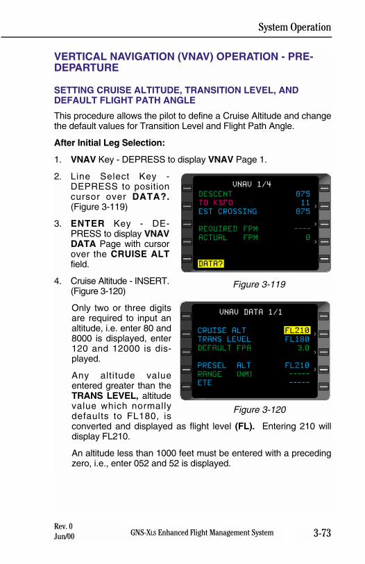
System Operation
3-73GNS-XLS Enhanced Flight Management SystemRev. 0Jun/00
VERTICAL NAVIGATION (VNAV) OPERATION - PRE-DEPARTURE
SETTING CRUISE ALTITUDE, TRANSITION LEVEL, ANDDEFAULT FLIGHT PATH ANGLE
This procedure allows the pilot to define a Cruise Altitude and changethe default values for Transition Level and Flight Path Angle.
After Initial Leg Selection:
1. VNAV Key - DEPRESS to display VNAV Page 1.
2. Line Select Key -DEPRESS to positioncursor over DATA?.(Figure 3-119)
3. ENTER Key - DE-PRESS to display VNAVDATA Page with cursorover the CRUISE ALTfield.
4. Cruise Altitude - INSERT.(Figure 3-120)
Only two or three digitsare required to input analtitude, i.e. enter 80 and8000 is displayed, enter120 and 12000 is dis-played.
Any altitude valueentered greater than theTRANS LEVEL, altitudevalue which normallydefaults to FL180, isconverted and displayed as flight level (FL). Entering 210 willdisplay FL210.
An altitude less than 1000 feet must be entered with a precedingzero, i.e., enter 052 and 52 is displayed.
DESCENT 875
TO KSFO 11
EST CROSSING 875
REQUIRED FPM ----
ACTUAL FPM 0
DATA?
VNAV 1/4
>
>
>
Figure 3-119
CRUISE ALT FL210
TRANS LEVEL FL180
DEFAULT FPA 3.0
PRESEL ALT FL210
RANGE (NM) -----
ETE -----
VNAV DATA 1/1
>
>
>
Figure 3-120
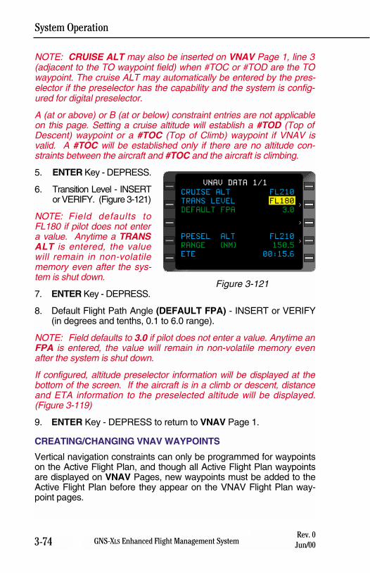
System Operation
3-74 GNS-XLS Enhanced Flight Management SystemRev. 0
Jun/00
NOTE: CRUISE ALT may also be inserted on VNAV Page 1, line 3(adjacent to the TO waypoint field) when #TOC or #TOD are the TOwaypoint. The cruise ALT may automatically be entered by the pres-elector if the preselector has the capability and the system is config-ured for digital preselector.
A (at or above) or B (at or below) constraint entries are not applicableon this page. Setting a cruise altitude will establish a #TOD (Top ofDescent) waypoint or a #TOC (Top of Climb) waypoint if VNAV isvalid. A #TOC will be established only if there are no altitude con-straints between the aircraft and #TOC and the aircraft is climbing.
5. ENTER Key - DEPRESS.
6. Transition Level - INSERTor VERIFY. (Figure 3-121)
NOTE: Field defaults toFL180 if pilot does not entera value. Anytime a TRANSALT is entered, the valuewill remain in non-volatilememory even after the sys-tem is shut down.
7. ENTER Key - DEPRESS.
8. Default Flight Path Angle (DEFAULT FPA) - INSERT or VERIFY(in degrees and tenths, 0.1 to 6.0 range).
NOTE: Field defaults to 3.0 if pilot does not enter a value. Anytime anFPA is entered, the value will remain in non-volatile memory evenafter the system is shut down.
If configured, altitude preselector information will be displayed at thebottom of the screen. If the aircraft is in a climb or descent, distanceand ETA information to the preselected altitude will be displayed.(Figure 3-119)
9. ENTER Key - DEPRESS to return to VNAV Page 1.
CREATING/CHANGING VNAV WAYPOINTS
Vertical navigation constraints can only be programmed for waypointson the Active Flight Plan, and though all Active Flight Plan waypointsare displayed on VNAV Pages, new waypoints must be added to theActive Flight Plan before they appear on the VNAV Flight Plan way-point pages.
CRUISE ALT FL210
TRANS LEVEL FL180
DEFAULT FPA 3.0
PRESEL ALT FL210
RANGE (NM) 150.5
ETE 00:15.6
VNAV DATA 1/1
>
>
>
Figure 3-121
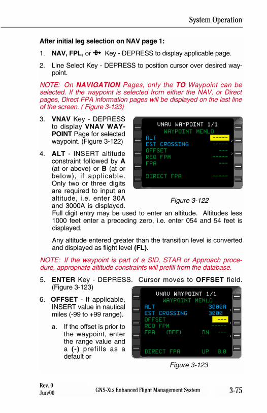
System Operation
3-75GNS-XLS Enhanced Flight Management SystemRev. 0Jun/00
After initial leg selection on NAV page 1:
1. NAV, FPL, or d Key - DEPRESS to display applicable page.
2. Line Select Key - DEPRESS to position cursor over desired way-point.
NOTE: On NAVIGATION Pages, only the TO Waypoint can beselected. If the waypoint is selected from either the NAV, or Directpages, Direct FPA information pages will be displayed on the last lineof the screen. ( Figure 3-123)
3. VNAV Key - DEPRESSto display VNAV WAY-POINT Page for selectedwaypoint. (Figure 3-122)
4. ALT - INSERT altitudeconstraint followed by A(at or above) or B (at orbelow), if applicable.Only two or three digitsare required to input analtitude, i.e. enter 30Aand 3000A is displayed.Full digit entry may be used to enter an altitude. Altitudes less1000 feet enter a preceding zero, i.e. enter 054 and 54 feet isdisplayed.
Any altitude entered greater than the transition level is convertedand displayed as flight level (FL).
NOTE: If the waypoint is part of a SID, STAR or Approach proce-dure, appropriate altitude constraints will prefill from the database.
5. ENTER Key - DEPRESS. Cursor moves to OFFSET field.(Figure 3-123)
6. OFFSET - If applicable,INSERT value in nauticalmiles (-99 to +99 range).
a. If the offset is prior tothe waypoint, enterthe range value anda (-) prefills as adefault or
WAYPOINT MENLO
ALT 3000A
EST CROSSING 3000
OFFSET ---
REQ FPM -----
FPA (DEF) DN ---
DIRECT FPA UP 0.0
VNAV WAYPOINT 1/1
>
>
>
Figure 3-123
WAYPOINT MENLO
ALT -----
EST CROSSING -----
OFFSET ---
REQ FPM -----
FPA ---
DIRECT FPA -----
VNAV WAYPOINT 1/1
>
>
Figure 3-122
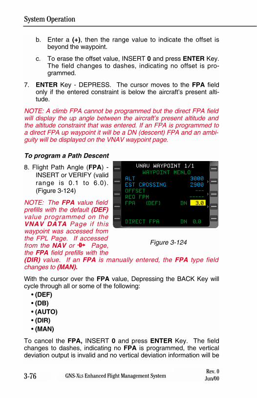
System Operation
3-76 GNS-XLS Enhanced Flight Management SystemRev. 0
Jun/00
b. Enter a (+), then the range value to indicate the offset isbeyond the waypoint.
c. To erase the offset value, INSERT 0 and press ENTER Key.The field changes to dashes, indicating no offset is pro-grammed.
7. ENTER Key - DEPRESS. The cursor moves to the FPA fieldonly if the entered constraint is below the aircraft’s present alti-tude.
NOTE: A climb FPA cannot be programmed but the direct FPA fieldwill display the up angle between the aircraft’s present altitude andthe altitude constraint that was entered. If an FPA is programmed toa direct FPA up waypoint it will be a DN (descent) FPA and an ambi-guity will be displayed on the VNAV waypoint page.
To program a Path Descent
8. Flight Path Angle (FPA) -INSERT or VERIFY (validrange is 0.1 to 6.0).(Figure 3-124)
NOTE: The FPA value fieldprefills with the default (DEF)value programmed on theVNAV DATA Page if thiswaypoint was accessed fromthe FPL Page. If accessedfrom the NAV or d Page,the FPA field prefills with the(DIR) value. If an FPA is manually entered, the FPA type fieldchanges to (MAN).
With the cursor over the FPA value, Depressing the BACK Key willcycle through all or some of the following:
• (DEF) • (DB)• (AUTO) • (DIR) • (MAN)
To cancel the FPA, INSERT 0 and press ENTER Key. The fieldchanges to dashes, indicating no FPA is programmed, the verticaldeviation output is invalid and no vertical deviation information will be
WAYPOINT MENLO
ALT 3000
EST CROSSING 2900
OFFSET ---
REQ FPM -----
FPA (DEF) DN 3.0
DIRECT FPA DN 0.0
VNAV WAYPOINT 1/1
>
>
>
Figure 3-124
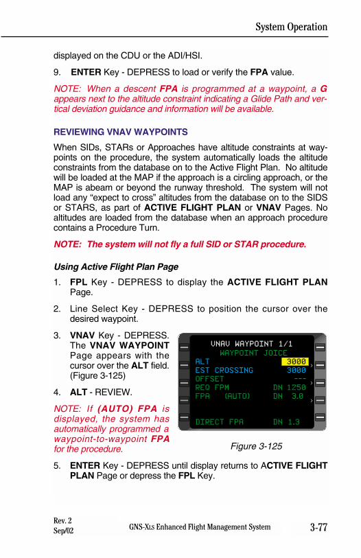
System Operation
3-77GNS-XLS Enhanced Flight Management SystemRev. 2Sep/02
displayed on the CDU or the ADI/HSI.
9. ENTER Key - DEPRESS to load or verify the FPA value.
NOTE: When a descent FPA is programmed at a waypoint, a Gappears next to the altitude constraint indicating a Glide Path and ver-tical deviation guidance and information will be available.
REVIEWING VNAV WAYPOINTS
When SIDs, STARs or Approaches have altitude constraints at way-points on the procedure, the system automatically loads the altitudeconstraints from the database on to the Active Flight Plan. No altitudewill be loaded at the MAP if the approach is a circling approach, or theMAP is abeam or beyond the runway threshold. The system will notload any “expect to cross” altitudes from the database on to the SIDSor STARS, as part of ACTIVE FLIGHT PLAN or VNAV Pages. Noaltitudes are loaded from the database when an approach procedurecontains a Procedure Turn.
NOTE: The system will not fly a full SID or STAR procedure.
Using Active Flight Plan Page
1. FPL Key - DEPRESS to display the ACTIVE FLIGHT PLANPage.
2. Line Select Key - DEPRESS to position the cursor over thedesired waypoint.
3. VNAV Key - DEPRESS.The VNAV WAYPOINTPage appears with thecursor over the ALT field.(Figure 3-125)
4. ALT - REVIEW.
NOTE: If (AUTO) FPA isdisplayed, the system hasautomatically programmed awaypoint-to-waypoint FPAfor the procedure.
5. ENTER Key - DEPRESS until display returns to ACTIVE FLIGHTPLAN Page or depress the FPL Key.
WAYPOINT JOICE
ALT 3000
EST CROSSING 3000
OFFSET ---
REQ FPM DN 1250
FPA (AUTO) DN 3.0
DIRECT FPA DN 1.3
VNAV WAYPOINT 1/1
>
>
>
Figure 3-125
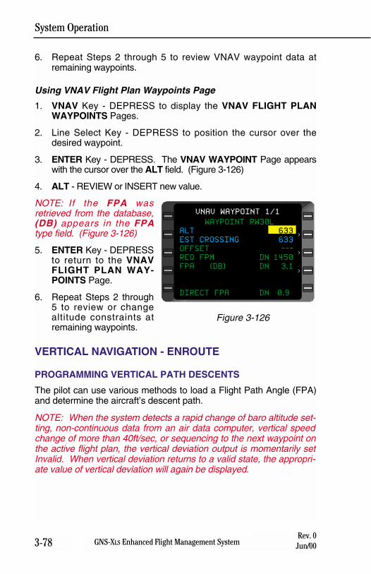
System Operation
3-78 GNS-XLS Enhanced Flight Management SystemRev. 0
Jun/00
6. Repeat Steps 2 through 5 to review VNAV waypoint data atremaining waypoints.
Using VNAV Flight Plan Waypoints Page
1. VNAV Key - DEPRESS to display the VNAV FLIGHT PLANWAYPOINTS Pages.
2. Line Select Key - DEPRESS to position the cursor over thedesired waypoint.
3. ENTER Key - DEPRESS. The VNAV WAYPOINT Page appearswith the cursor over the ALT field. (Figure 3-126)
4. ALT - REVIEW or INSERT new value.
NOTE: If the FPA wasretrieved from the database,(DB) appears in the FPAtype field. (Figure 3-126)
5. ENTER Key - DEPRESSto return to the VNAVFLIGHT PLAN WAY-POINTS Page.
6. Repeat Steps 2 through5 to review or changealtitude constraints atremaining waypoints.
VERTICAL NAVIGATION - ENROUTE
PROGRAMMING VERTICAL PATH DESCENTS
The pilot can use various methods to load a Flight Path Angle (FPA)and determine the aircraft’s descent path.
NOTE: When the system detects a rapid change of baro altitude set-ting, non-continuous data from an air data computer, vertical speedchange of more than 40ft/sec, or sequencing to the next waypoint onthe active flight plan, the vertical deviation output is momentarily setInvalid. When vertical deviation returns to a valid state, the appropri-ate value of vertical deviation will again be displayed.
WAYPOINT RW30L
ALT 633
EST CROSSING 633
OFFSET ---
REQ FPM DN 1450
FPA (DB) DN 3.1
DIRECT FPA DN 0.9
VNAV WAYPOINT 1/1
>
>
>
Figure 3-126
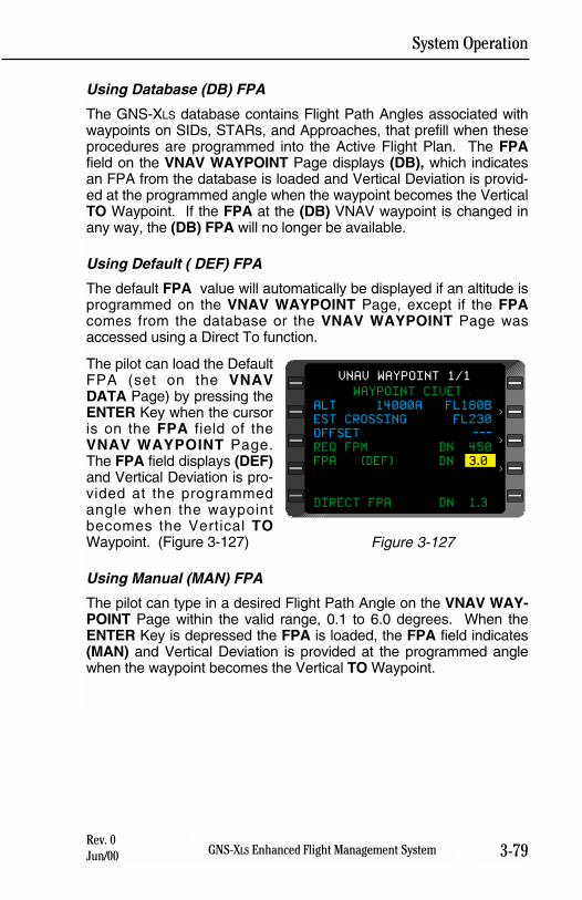
System Operation
3-79GNS-XLS Enhanced Flight Management SystemRev. 0Jun/00
Using Database (DB) FPA
The GNS-XLS database contains Flight Path Angles associated withwaypoints on SIDs, STARs, and Approaches, that prefill when theseprocedures are programmed into the Active Flight Plan. The FPAfield on the VNAV WAYPOINT Page displays (DB), which indicatesan FPA from the database is loaded and Vertical Deviation is provid-ed at the programmed angle when the waypoint becomes the VerticalTO Waypoint. If the FPA at the (DB) VNAV waypoint is changed inany way, the (DB) FPA will no longer be available.
Using Default ( DEF) FPA
The default FPA value will automatically be displayed if an altitude isprogrammed on the VNAV WAYPOINT Page, except if the FPAcomes from the database or the VNAV WAYPOINT Page wasaccessed using a Direct To function.
The pilot can load the DefaultFPA (set on the VNAVDATA Page) by pressing theENTER Key when the cursoris on the FPA field of theVNAV WAYPOINT Page.The FPA field displays (DEF)and Vertical Deviation is pro-vided at the programmedangle when the waypointbecomes the Vertical TOWaypoint. (Figure 3-127)
Using Manual (MAN) FPA
The pilot can type in a desired Flight Path Angle on the VNAV WAY-POINT Page within the valid range, 0.1 to 6.0 degrees. When theENTER Key is depressed the FPA is loaded, the FPA field indicates(MAN) and Vertical Deviation is provided at the programmed anglewhen the waypoint becomes the Vertical TO Waypoint.
WAYPOINT CIVET
ALT 14000A FL180B
EST CROSSING FL230
OFFSET ---
REQ FPM DN 450
FPA (DEF) DN 3.0
DIRECT FPA DN 1.3
VNAV WAYPOINT 1/1
>
>
>
Figure 3-127
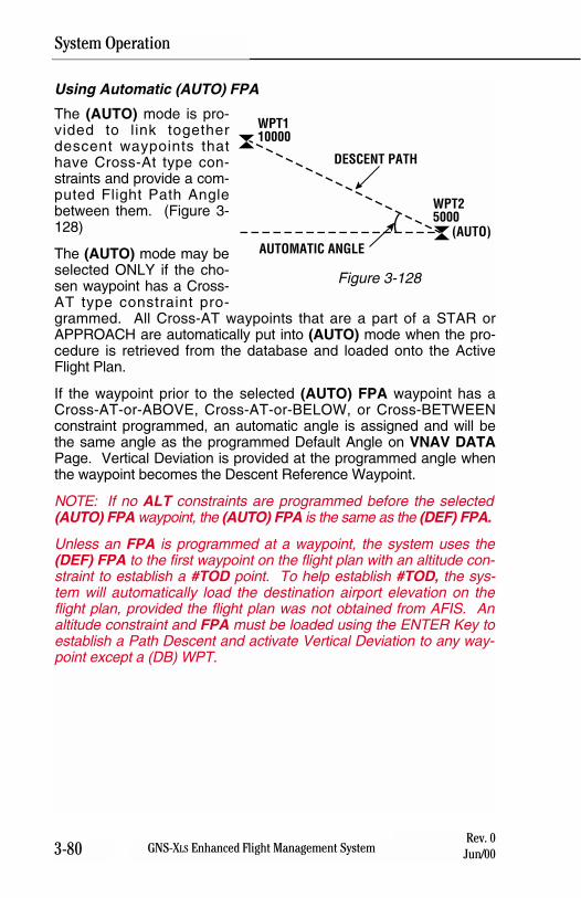
3-80 GNS-XLS Enhanced Flight Management SystemRev. 0
Jun/00
Using Automatic (AUTO) FPA
The (AUTO) mode is pro-vided to link togetherdescent waypoints thathave Cross-At type con-straints and provide a com-puted Flight Path Anglebetween them. (Figure 3-128)
The (AUTO) mode may beselected ONLY if the cho-sen waypoint has a Cross-AT type constraint pro-grammed. All Cross-AT waypoints that are a part of a STAR orAPPROACH are automatically put into (AUTO) mode when the pro-cedure is retrieved from the database and loaded onto the ActiveFlight Plan.
If the waypoint prior to the selected (AUTO) FPA waypoint has aCross-AT-or-ABOVE, Cross-AT-or-BELOW, or Cross-BETWEENconstraint programmed, an automatic angle is assigned and will bethe same angle as the programmed Default Angle on VNAV DATAPage. Vertical Deviation is provided at the programmed angle whenthe waypoint becomes the Descent Reference Waypoint.
NOTE: If no ALT constraints are programmed before the selected(AUTO) FPA waypoint, the (AUTO) FPA is the same as the (DEF) FPA.
Unless an FPA is programmed at a waypoint, the system uses the(DEF) FPA to the first waypoint on the flight plan with an altitude con-straint to establish a #TOD point. To help establish #TOD, the sys-tem will automatically load the destination airport elevation on theflight plan, provided the flight plan was not obtained from AFIS. Analtitude constraint and FPA must be loaded using the ENTER Key toestablish a Path Descent and activate Vertical Deviation to any way-point except a (DB) WPT.
System Operation
WPT110000
WPT25000
(AUTO)
DESCENT PATH
AUTOMATIC ANGLE
Figure 3-128
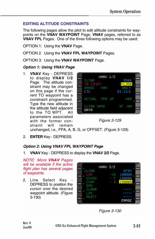
3-81GNS-XLS Enhanced Flight Management SystemRev. 0Jun/00
EDITING ALTITUDE CONSTRAINTS
The following pages allow the pilot to edit altitude constraints for way-points on the VNAV WAYPOINT Page, VNAV pages, referred to asVNAV FPL Pages. One of the three following options may be used:
OPTION 1: Using the VNAV Page.
OPTION 2. Using the VNAV FPL WAYPOINT Pages.
OPTION 3: Using the VNAV WAYPOINT Page.
Option 1: Using VNAV Page
1. VNAV Key - DEPRESSto display VNAV 1/2Page. The altitude con-straint may be changedon this page if the cur-rent TO waypoint has aconstraint programmed.Type the new altitude inthe altitude field adjacentto the TO WPT. Allparameters associatedwith the former con-straint will remainunchanged, i.e., FPA, A, B, G, or OFFSET. (Figure 3-129)
2. ENTER Key - DEPRESS.
Option 2: Using VNAV FPL WAYPOINT Page
1. VNAV Key - DEPRESS to display the VNAV 2/2 Page.
NOTE: More VNAV Pageswill be available if the activeflight plan has several pagesof waypoints.
2. Line Select Key -DEPRESS to position thecursor over the desiredwaypoint altitude. (Figure3-130)
System Operation
CLIMB 8754
LAX -10 10000A
KEGGS - 2 13000A
COOP - 3 15000A
DAG
CLARR -----
LAS -----
RENTT -----
ERASE
VNAV 2/2
>
>
>
>
>
<
<
<
<
<
Figure 3-130
CLIMB 5566
TO CIVET FL350
RANGE (NM) 300.4
ETE 01:13.5
ACTUAL FPM UP 400
CLIMB GRAD 97 /NM
DATA
VNAV 1/2
>
>
>
Figure 3-129
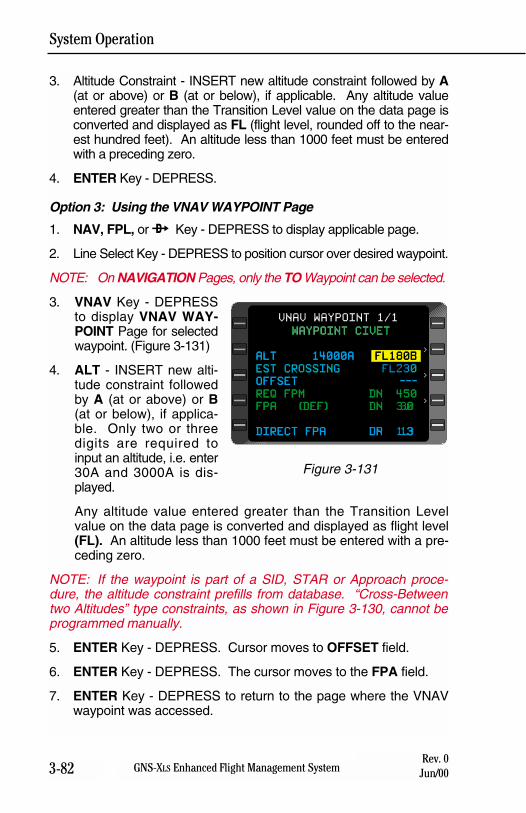
System Operation
3-82 GNS-XLS Enhanced Flight Management SystemRev. 0
Jun/00
3. Altitude Constraint - INSERT new altitude constraint followed by A(at or above) or B (at or below), if applicable. Any altitude valueentered greater than the Transition Level value on the data page isconverted and displayed as FL (flight level, rounded off to the near-est hundred feet). An altitude less than 1000 feet must be enteredwith a preceding zero.
4. ENTER Key - DEPRESS.
Option 3: Using the VNAV WAYPOINT Page
1. NAV, FPL, or d Key - DEPRESS to display applicable page.
2. Line Select Key - DEPRESS to position cursor over desired waypoint.
NOTE: On NAVIGATION Pages, only the TO Waypoint can be selected.
3. VNAV Key - DEPRESSto display VNAV WAY-POINT Page for selectedwaypoint. (Figure 3-131)
4. ALT - INSERT new alti-tude constraint followedby A (at or above) or B(at or below), if applica-ble. Only two or threedigits are required toinput an altitude, i.e. enter30A and 3000A is dis-played.
Any altitude value entered greater than the Transition Levelvalue on the data page is converted and displayed as flight level(FL). An altitude less than 1000 feet must be entered with a pre-ceding zero.
NOTE: If the waypoint is part of a SID, STAR or Approach proce-dure, the altitude constraint prefills from database. “Cross-Betweentwo Altitudes” type constraints, as shown in Figure 3-130, cannot beprogrammed manually.
5. ENTER Key - DEPRESS. Cursor moves to OFFSET field.
6. ENTER Key - DEPRESS. The cursor moves to the FPA field.
7. ENTER Key - DEPRESS to return to the page where the VNAVwaypoint was accessed.
WAYPOINT CIVET
ALT 14000A FL180B
EST CROSSING 0
OFFSET ---
REQ FPM DN 450
FPA (DEF) DN 3.0
DIRECT FPA UP 1.3
VNAV WAYPOINT 1/1
>
>
>
WAYPOINT CIVET
ALT 14000A FL180B
EST CROSSING FL230
OFFSET ---
REQ FPM DN 450
FPA (DEF) DN 3.0
DIRECT FPA DN 1.3
Figure 3-131
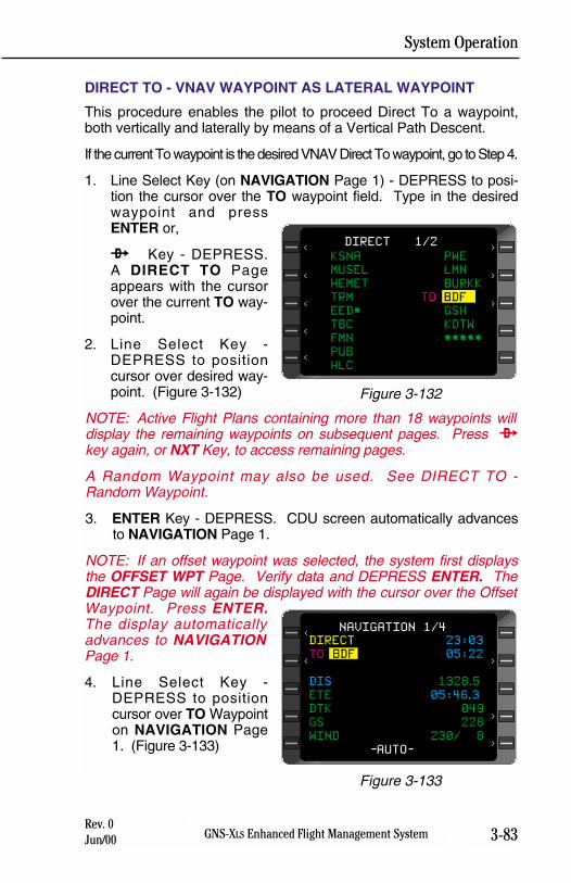
System Operation
3-83GNS-XLS Enhanced Flight Management SystemRev. 0Jun/00
DIRECT TO - VNAV WAYPOINT AS LATERAL WAYPOINT
This procedure enables the pilot to proceed Direct To a waypoint,both vertically and laterally by means of a Vertical Path Descent.
If the current To waypoint is the desired VNAV Direct To waypoint, go to Step 4.
1. Line Select Key (on NAVIGATION Page 1) - DEPRESS to posi-tion the cursor over the TO waypoint field. Type in the desiredwaypoint and pressENTER or,
d Key - DEPRESS.A DIRECT TO Pageappears with the cursorover the current TO way-point.
2. Line Select Key -DEPRESS to positioncursor over desired way-point. (Figure 3-132)
NOTE: Active Flight Plans containing more than 18 waypoints willdisplay the remaining waypoints on subsequent pages. Press dkey again, or NXT Key, to access remaining pages.
A Random Waypoint may also be used. See DIRECT TO -Random Waypoint.
3. ENTER Key - DEPRESS. CDU screen automatically advancesto NAVIGATION Page 1.
NOTE: If an offset waypoint was selected, the system first displaysthe OFFSET WPT Page. Verify data and DEPRESS ENTER. TheDIRECT Page will again be displayed with the cursor over the OffsetWaypoint. Press ENTER.The display automaticallyadvances to NAVIGATIONPage 1.
4. Line Select Key -DEPRESS to positioncursor over TO Waypointon NAVIGATION Page1. (Figure 3-133)
DIRECT 23:03
TO BDF 05:22
DIS 1328.5
ETE 05:46.3
DTK 049
GS 228
WIND 230/ 8
-AUTO-
NAVIGATION 1/4
<
>
>
>
<
Figure 3-133
KSNA PWE
MUSEL LMN
HEMET BURKK
TRM TO BDF
EED* GSH
TBC KDTW
FMN *****
PUB
HLC
DIRECT 1/2
>
>
>
<
<
<
<
<
Figure 3-132
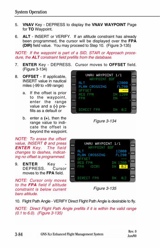
System Operation
3-84 GNS-XLS Enhanced Flight Management SystemRev. 0
Jun/00
5. VNAV Key - DEPRESS to display the VNAV WAYPOINT Pagefor TO Waypoint.
6. ALT - INSERT or VERIFY. If an altitude constraint has alreadybeen programmed, the cursor will be displayed over the FPA(DIR) field value. You may proceed to Step 10. (Figure 3-135)
NOTE: If the waypoint is part of a SID, STAR or Approach proce-dure, the ALT constraint field prefills from the database.
7. ENTER Key - DEPRESS. Cursor moves to OFFSET field.(Figure 3-134)
8. OFFSET - If applicable,INSERT value in nauticalmiles (-99 to +99 range)
a. If the offset is priorto the waypoint,enter the rangevalue and a (-) pre-fills as a default or
b. enter a (+), then therange value to indi-cate the offset isbeyond the waypoint.
NOTE: To erase the offsetvalue, INSERT 0 and pressENTER Key. The fieldchanges to dashes, indicat-ing no offset is programmed.
9. ENTER Key -DEPRESS. Cursormoves to the FPA field.
NOTE: Cursor only movesto the FPA field if altitudeconstraint is below currentbaro altitude.
10. Flight Path Angle - VERIFY Direct Flight Path Angle is desirable to fly.
NOTE: Direct Flight Path Angle prefills if it is within the valid range(0.1 to 6.0). (Figure 3-135)
WAYPOINT BDF
ALT 12000
PLAN CROSSING FL290
OFFSET ---
REQ FPM DN 1200
FPA (DIR) DN 0.2
DIRECT FPA DN 0.2
VNAV WAYPOINT 1/1
>
>
>
Figure 3-135
WAYPOINT BDF
ALT 12000
PLAN CROSSING FL290
OFFSET ---
REQ FPM DN 1200
FPA DN ---
DIRECT FPA DN 0.2
VNAV WAYPOINT 1/1
>
>
>
Figure 3-134
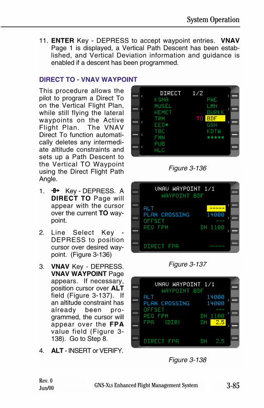
System Operation
3-85GNS-XLS Enhanced Flight Management SystemRev. 0Jun/00
11. ENTER Key - DEPRESS to accept waypoint entries. VNAVPage 1 is displayed, a Vertical Path Descent has been estab-lished, and Vertical Deviation information and guidance isenabled if a descent has been programmed.
DIRECT TO - VNAV WAYPOINT
This procedure allows thepilot to program a Direct Toon the Vertical Flight Plan,while still flying the lateralwaypoints on the ActiveFlight Plan. The VNAVDirect To function automati-cally deletes any intermedi-ate altitude constraints andsets up a Path Descent tothe Vertical TO Waypointusing the Direct Flight PathAngle.
1. d Key - DEPRESS. ADIRECT TO Page willappear with the cursorover the current TO way-point.
2. Line Select Key -DEPRESS to positioncursor over desired way-point. (Figure 3-136)
3. VNAV Key - DEPRESS.VNAV WAYPOINT Pageappears. If necessary,position cursor over ALTfield (Figure 3-137). Ifan altitude constraint hasalready been pro-grammed, the cursor willappear over the FPAvalue field (Figure 3-138). Go to Step 8.
4. ALT - INSERT or VERIFY.
WAYPOINT BDF
ALT -----
PLAN CROSSING 14000
OFFSET ---
REQ FPM DN 1100
DIRECT FPA -----
VNAV WAYPOINT 1/1
>
>
>
Figure 3-137
WAYPOINT BDF
ALT 14000
PLAN CROSSING 14000
OFFSET ---
REQ FPM DN 1100
FPA (DIR) DN 2.5
DIRECT FPA DN 2.5
VNAV WAYPOINT 1/1
>
>
>
Figure 3-138
KSNA PWE
MUSEL LMN
HEMET BURKK
TRM TO BDF
EED* GSH
TBC KDTW
FMN *****
PUB
HLC
DIRECT 1/2
>
>
>
<
<
<
<
<
Figure 3-136
System Operation
3-86 GNS-XLS Enhanced Flight Management SystemRev. 0
Jun/00
5. ENTER Key - DEPRESS. Cursor moves to OFFSET field.
6. OFFSET - If applicable, INSERT value in nautical miles (-99 to+99 range).
a. If the offset is prior to the waypoint, enter the range valueand a (-) prefills as a default or
b. enter a (+), then the range value to indicate the offset isbeyond the waypoint
7. ENTER Key - DEPRESS. Cursor moves to FPA field.
8. Flight Path Angle - VERIFY or INSERT (in degrees and tenths,0.1 to 6.0 range).
NOTE: Direct Flight Path Angle prefills if it is within the valid rangeand an ALT is programmed. (Figure 3-138)
9. ENTER Key - DEPRESS to accept waypoint entries and returnto VNAV Page 1.
CREATING VNAV PROFILE WAYPOINTS
VNAV profile waypoints (#TOC, #TOD, and #PRESL) are used toprovide a prediction of the position of the aircraft on the vertical flightpath. These are non-enterable waypoints computed by the systembased on current ground speed and vertical speed.
Top of Climb (#TOC)
Top of Climb Altitude is obtained from either the CRUISE ALTentered by the pilot on the VNAV DATA Page, or from the AltitudePreselector setting, if available. When the aircraft arrives at the pre-selected altitude, the system will automatically set cruise altitude tothe pre-selected altitude which will then provide a #TOD prediction.
If vertical climb constraints are programmed, #TOC will automaticallyappear as the Vertical To Waypoint when the aircraft laterally passeswithin 1 mile the last vertical waypoint on the active flight plan thathas a climb constraint. Once the aircraft has crossed the final climbconstraint waypoint, #TOC will then become the Vertical ToWaypoint. If there are no vertical constraints programmed for climb,#TOC will be displayed as the first vertical waypoint as long as theaircraft is in a climb.
When the programmed cruise altitude is reached, #TOC is removedfrom the VNAV Flight Plan, and #TOD becomes the Vertical ToWaypoint.
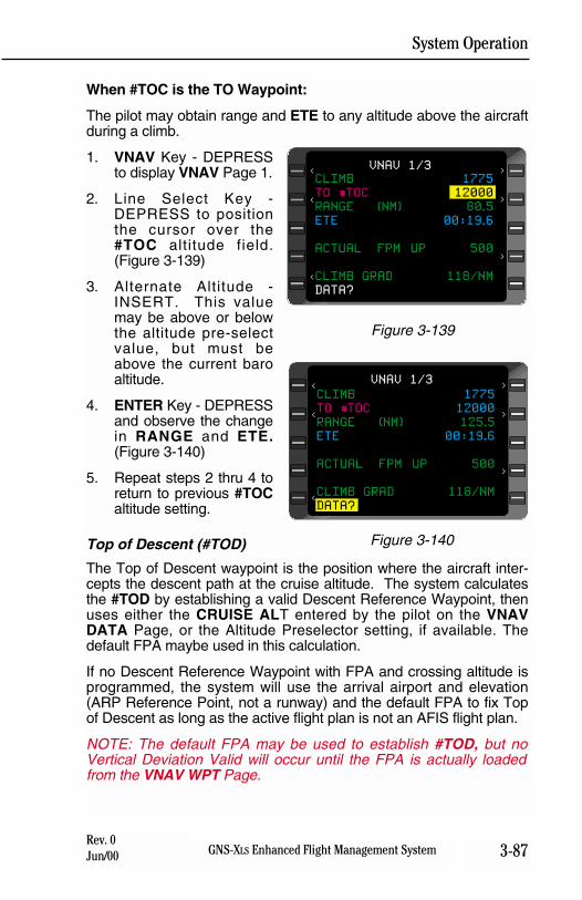
System Operation
3-87GNS-XLS Enhanced Flight Management SystemRev. 0Jun/00
When #TOC is the TO Waypoint:
The pilot may obtain range and ETE to any altitude above the aircraftduring a climb.
1. VNAV Key - DEPRESSto display VNAV Page 1.
2. Line Select Key -DEPRESS to positionthe cursor over the#TOC altitude field.(Figure 3-139)
3. Alternate Altitude -INSERT. This valuemay be above or belowthe altitude pre-selectvalue, but must beabove the current baroaltitude.
4. ENTER Key - DEPRESSand observe the changein RANGE and ETE.(Figure 3-140)
5. Repeat steps 2 thru 4 toreturn to previous #TOCaltitude setting.
Top of Descent (#TOD)
The Top of Descent waypoint is the position where the aircraft inter-cepts the descent path at the cruise altitude. The system calculatesthe #TOD by establishing a valid Descent Reference Waypoint, thenuses either the CRUISE ALT entered by the pilot on the VNAVDATA Page, or the Altitude Preselector setting, if available. Thedefault FPA maybe used in this calculation.
If no Descent Reference Waypoint with FPA and crossing altitude isprogrammed, the system will use the arrival airport and elevation(ARP Reference Point, not a runway) and the default FPA to fix Topof Descent as long as the active flight plan is not an AFIS flight plan.
NOTE: The default FPA may be used to establish #TOD, but noVertical Deviation Valid will occur until the FPA is actually loadedfrom the VNAV WPT Page.
CLIMB 1775
TO #TOC 12000
RANGE (NM) 125.5
ETE 00:19.6
ACTUAL FPM UP 500
CLIMB GRAD 118/NM
DATA?
VNAV 1/3
>
>
>
<
<
<
Figure 3-140
CLIMB 1775
TO #TOC 12000
RANGE (NM) 80.5
ETE 00:19.6
ACTUAL FPM UP 500
CLIMB GRAD 118/NM
DATA?
VNAV 1/3
>
>
>
<
<
<
Figure 3-139
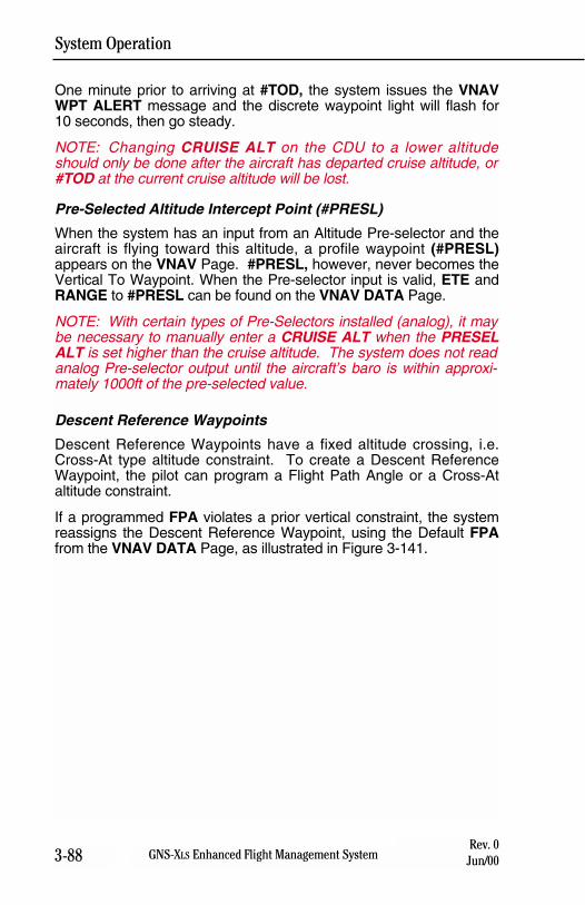
System Operation
3-88 GNS-XLS Enhanced Flight Management SystemRev. 0
Jun/00
One minute prior to arriving at #TOD, the system issues the VNAVWPT ALERT message and the discrete waypoint light will flash for10 seconds, then go steady.
NOTE: Changing CRUISE ALT on the CDU to a lower altitudeshould only be done after the aircraft has departed cruise altitude, or#TOD at the current cruise altitude will be lost.
Pre-Selected Altitude Intercept Point (#PRESL)
When the system has an input from an Altitude Pre-selector and theaircraft is flying toward this altitude, a profile waypoint (#PRESL)appears on the VNAV Page. #PRESL, however, never becomes theVertical To Waypoint. When the Pre-selector input is valid, ETE andRANGE to #PRESL can be found on the VNAV DATA Page.
NOTE: With certain types of Pre-Selectors installed (analog), it maybe necessary to manually enter a CRUISE ALT when the PRESELALT is set higher than the cruise altitude. The system does not readanalog Pre-selector output until the aircraft’s baro is within approxi-mately 1000ft of the pre-selected value.
Descent Reference Waypoints
Descent Reference Waypoints have a fixed altitude crossing, i.e.Cross-At type altitude constraint. To create a Descent ReferenceWaypoint, the pilot can program a Flight Path Angle or a Cross-Ataltitude constraint.
If a programmed FPA violates a prior vertical constraint, the systemreassigns the Descent Reference Waypoint, using the Default FPAfrom the VNAV DATA Page, as illustrated in Figure 3-141.
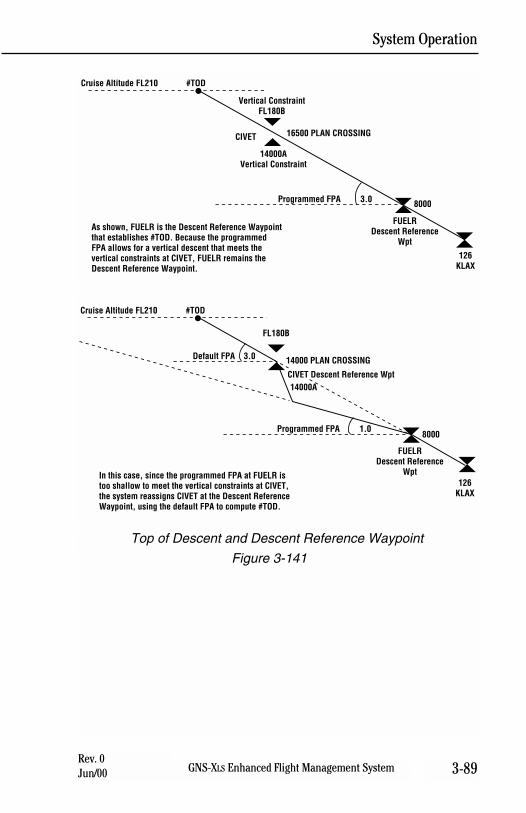
System Operation
3-89GNS-XLS Enhanced Flight Management SystemRev. 0Jun/00
Figure 3-141
#TOD
8000
FUELRDescent Reference
Wpt
126KLAX
Cruise Altitude FL210
Vertical ConstraintFL180B
16500 PLAN CROSSING
Programmed FPA 3.0
CIVET
14000AVertical Constraint
As shown, FUELR is the Descent Reference Waypoint that establishes #TOD. Because the programmed FPA allows for a vertical descent that meets the vertical constraints at CIVET, FUELR remains the Descent Reference Waypoint.
#TOD
8000
FUELRDescent Reference
Wpt126
KLAX
Cruise Altitude FL210
FL180B
14000 PLAN CROSSINGDefault FPA 3.0
Programmed FPA 1.0
CIVET Descent Reference Wpt14000A
In this case, since the programmed FPA at FUELR is too shallow to meet the vertical constraints at CIVET, the system reassigns CIVET at the Descent Reference Waypoint, using the default FPA to compute #TOD.
Top of Descent and Descent Reference Waypoint
System Operation
3-90 GNS-XLS Enhanced Flight Management SystemRev. 0
Jun/00
THIS PAGE INTENTIONALLY LEFT BLANK
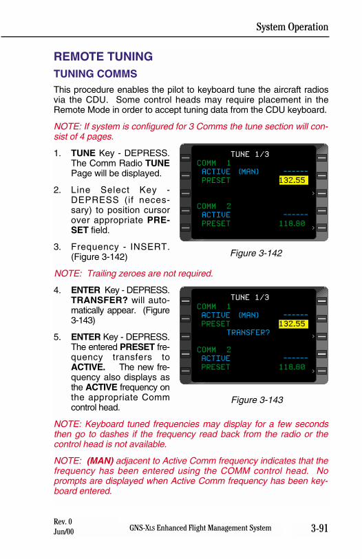
System Operation
3-91GNS-XLS Enhanced Flight Management SystemRev. 0Jun/00
REMOTE TUNINGTUNING COMMSThis procedure enables the pilot to keyboard tune the aircraft radiosvia the CDU. Some control heads may require placement in theRemote Mode in order to accept tuning data from the CDU keyboard.
NOTE: If system is configured for 3 Comms the tune section will con-sist of 4 pages.
1. TUNE Key - DEPRESS.The Comm Radio TUNEPage will be displayed.
2. Line Select Key -DEPRESS (if neces-sary) to position cursorover appropriate PRE-SET field.
3. Frequency - INSERT.(Figure 3-142)
NOTE: Trailing zeroes are not required.
4. ENTER Key - DEPRESS.TRANSFER? will auto-matically appear. (Figure3-143)
5. ENTER Key - DEPRESS.The entered PRESET fre-quency transfers toACTIVE. The new fre-quency also displays asthe ACTIVE frequency onthe appropriate Commcontrol head.
NOTE: Keyboard tuned frequencies may display for a few secondsthen go to dashes if the frequency read back from the radio or thecontrol head is not available.
NOTE: (MAN) adjacent to Active Comm frequency indicates that thefrequency has been entered using the COMM control head. Noprompts are displayed when Active Comm frequency has been key-board entered.
COMM 1
ACTIVE (MAN) ------
PRESET 132.55
COMM 2
ACTIVE ------
PRESET 118.80
TUNE 1/3
>
>
Figure 3-142
COMM 1
ACTIVE (MAN) ------
PRESET 132.55
TRANSFER?
COMM 2
ACTIVE ------
PRESET 118.80
TUNE 1/3
>
>
Figure 3-143
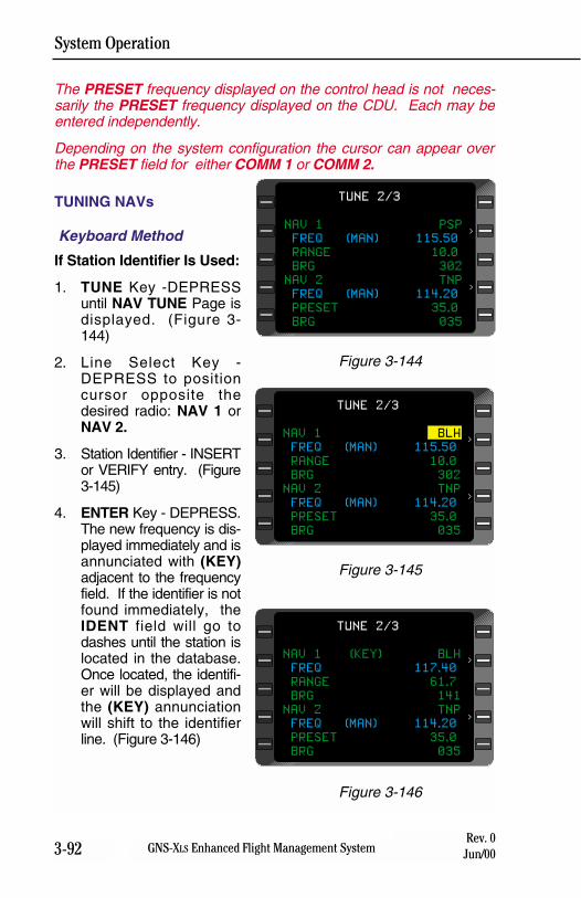
System Operation
3-92 GNS-XLS Enhanced Flight Management SystemRev. 0
Jun/00
The PRESET frequency displayed on the control head is not neces-sarily the PRESET frequency displayed on the CDU. Each may beentered independently.
Depending on the system configuration the cursor can appear overthe PRESET field for either COMM 1 or COMM 2.
TUNING NAVs
Keyboard Method
If Station Identifier Is Used:
1. TUNE Key -DEPRESSuntil NAV TUNE Page isdisplayed. (Figure 3-144)
2. Line Select Key -DEPRESS to positioncursor opposite thedesired radio: NAV 1 orNAV 2.
3. Station Identifier - INSERTor VERIFY entry. (Figure3-145)
4. ENTER Key - DEPRESS.The new frequency is dis-played immediately and isannunciated with (KEY)adjacent to the frequencyfield. If the identifier is notfound immediately, theIDENT field will go todashes until the station islocated in the database.Once located, the identifi-er will be displayed andthe (KEY) annunciationwill shift to the identifierline. (Figure 3-146)
NAV 1 PSP
FREQ (MAN) 115.50
RANGE 10.0
BRG 302
NAV 2 TNP
FREQ (MAN) 114.20
PRESET 35.0
BRG 035
TUNE 2/3
>
>
Figure 3-144
NAV 1 BLH
FREQ (MAN) 115.50
RANGE 10.0
BRG 302
NAV 2 TNP
FREQ (MAN) 114.20
PRESET 35.0
BRG 035
TUNE 2/3
>
>
Figure 3-145
NAV 1 (KEY) BLH
FREQ 117.40
RANGE 61.7
BRG 141
NAV 2 TNP
FREQ (MAN) 114.20
PRESET 35.0
BRG 035
TUNE 2/3
>
>
Figure 3-146
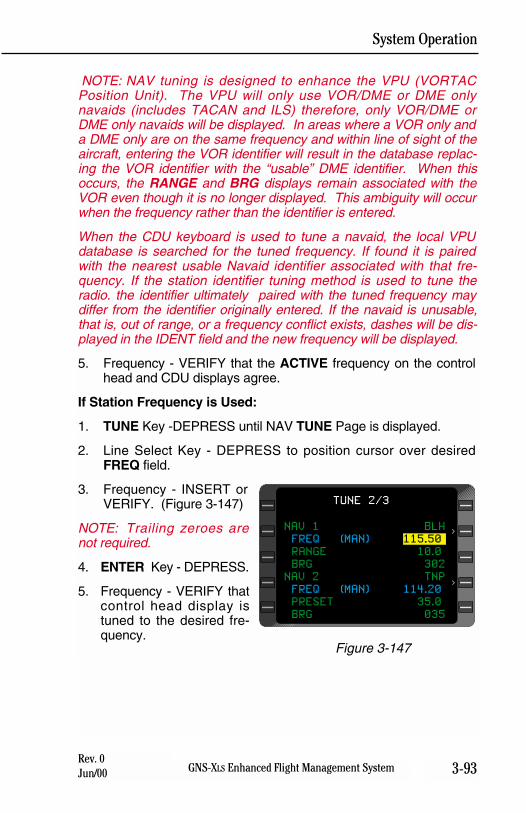
System Operation
3-93GNS-XLS Enhanced Flight Management SystemRev. 0Jun/00
NOTE: NAV tuning is designed to enhance the VPU (VORTACPosition Unit). The VPU will only use VOR/DME or DME onlynavaids (includes TACAN and ILS) therefore, only VOR/DME orDME only navaids will be displayed. In areas where a VOR only anda DME only are on the same frequency and within line of sight of theaircraft, entering the VOR identifier will result in the database replac-ing the VOR identifier with the “usable” DME identifier. When thisoccurs, the RANGE and BRG displays remain associated with theVOR even though it is no longer displayed. This ambiguity will occurwhen the frequency rather than the identifier is entered.
When the CDU keyboard is used to tune a navaid, the local VPUdatabase is searched for the tuned frequency. If found it is pairedwith the nearest usable Navaid identifier associated with that fre-quency. If the station identifier tuning method is used to tune theradio. the identifier ultimately paired with the tuned frequency maydiffer from the identifier originally entered. If the navaid is unusable,that is, out of range, or a frequency conflict exists, dashes will be dis-played in the IDENT field and the new frequency will be displayed.
5. Frequency - VERIFY that the ACTIVE frequency on the controlhead and CDU displays agree.
If Station Frequency is Used:
1. TUNE Key -DEPRESS until NAV TUNE Page is displayed.
2. Line Select Key - DEPRESS to position cursor over desiredFREQ field.
3. Frequency - INSERT orVERIFY. (Figure 3-147)
NOTE: Trailing zeroes arenot required.
4. ENTER Key - DEPRESS.
5. Frequency - VERIFY thatcontrol head display istuned to the desired fre-quency.
NAV 1 BLH
FREQ (MAN) 115.50
RANGE 10.0
BRG 302
NAV 2 TNP
FREQ (MAN) 114.20
PRESET 35.0
BRG 035
TUNE 2/3
>
>
Figure 3-147
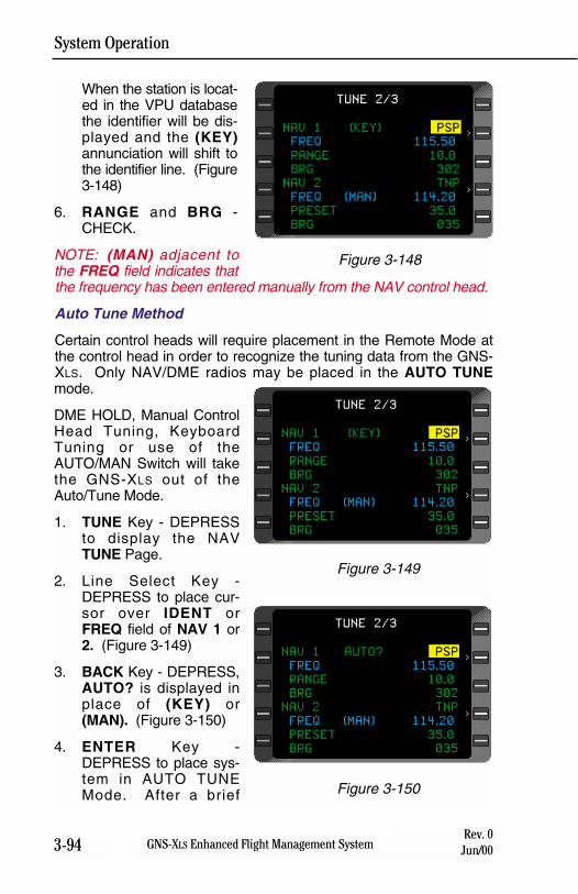
System Operation
3-94 GNS-XLS Enhanced Flight Management SystemRev. 0
Jun/00
When the station is locat-ed in the VPU databasethe identifier will be dis-played and the (KEY)annunciation will shift tothe identifier line. (Figure3-148)
6. RANGE and BRG -CHECK.
NOTE: (MAN) adjacent tothe FREQ field indicates thatthe frequency has been entered manually from the NAV control head.
Auto Tune Method
Certain control heads will require placement in the Remote Mode atthe control head in order to recognize the tuning data from the GNS-XLS. Only NAV/DME radios may be placed in the AUTO TUNEmode.
DME HOLD, Manual ControlHead Tuning, KeyboardTuning or use of theAUTO/MAN Switch will takethe GNS-XLS out of theAuto/Tune Mode.
1. TUNE Key - DEPRESSto display the NAVTUNE Page.
2. Line Select Key -DEPRESS to place cur-sor over IDENT orFREQ field of NAV 1 or2. (Figure 3-149)
3. BACK Key - DEPRESS,AUTO? is displayed inplace of (KEY) or(MAN). (Figure 3-150)
4. ENTER Key -DEPRESS to place sys-tem in AUTO TUNEMode. After a brief
NAV 1 (KEY) PSP
FREQ 115.50
RANGE 10.0
BRG 302
NAV 2 TNP
FREQ (MAN) 114.20
PRESET 35.0
BRG 035
TUNE 2/3
>
>
Figure 3-149
NAV 1 AUTO? PSP
FREQ 115.50
RANGE 10.0
BRG 302
NAV 2 TNP
FREQ (MAN) 114.20
PRESET 35.0
BRG 035
TUNE 2/3
>
>
Figure 3-150
NAV 1 (KEY) PSP
FREQ 115.50
RANGE 10.0
BRG 302
NAV 2 TNP
FREQ (MAN) 114.20
PRESET 35.0
BRG 035
TUNE 2/3
>
>
Figure 3-148
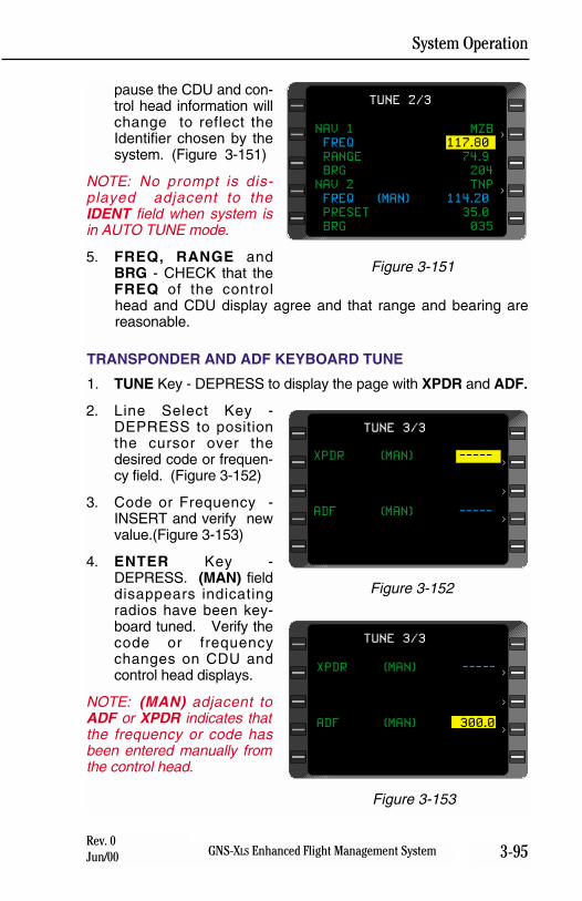
System Operation
3-95GNS-XLS Enhanced Flight Management SystemRev. 0Jun/00
pause the CDU and con-trol head information willchange to reflect theIdentifier chosen by thesystem. (Figure 3-151)
NOTE: No prompt is dis-played adjacent to theIDENT field when system isin AUTO TUNE mode.
5. FREQ, RANGE andBRG - CHECK that theFREQ of the controlhead and CDU display agree and that range and bearing arereasonable.
TRANSPONDER AND ADF KEYBOARD TUNE
1. TUNE Key - DEPRESS to display the page with XPDR and ADF.
2. Line Select Key -DEPRESS to positionthe cursor over thedesired code or frequen-cy field. (Figure 3-152)
3. Code or Frequency -INSERT and verify newvalue.(Figure 3-153)
4. ENTER Key -DEPRESS. (MAN) fielddisappears indicatingradios have been key-board tuned. Verify thecode or frequencychanges on CDU andcontrol head displays.
NOTE: (MAN) adjacent toADF or XPDR indicates thatthe frequency or code hasbeen entered manually fromthe control head.
NAV 1 MZB
FREQ 117.80
RANGE 74.9
BRG 204
NAV 2 TNP
FREQ (MAN) 114.20
PRESET 35.0
BRG 035
TUNE 2/3
>
>
Figure 3-151
XPDR (MAN) -----
ADF (MAN) -----
TUNE 3/3
>
>
>
Figure 3-152
XPDR (MAN) -----
ADF (MAN) 300.0
TUNE 3/3
>
>
>
Figure 3-153

System Operation
3-96 GNS-XLS Enhanced Flight Management SystemRev. 0
Jun/00
THIS PAGE INTENTIONALLY LEFT BLANK
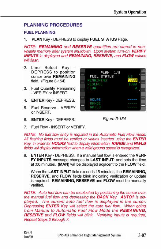
System Operation
3-97GNS-XLS Enhanced Flight Management SystemRev. 0Jun/00
PLANNING PROCEDURES
FUEL PLANNING
1. PLAN Key - DEPRESS to display FUEL STATUS Page.
NOTE: REMAINING and RESERVE quantities are stored in non-volatile memory after system shutdown. Upon system turn-on, VERIFYINPUTS is displayed and REMAINING, RESERVE, and FLOW valueswill flash.
2. Line Select Key -DEPRESS to positioncursor over REMAININGfield. (Figure 3-154)
3. Fuel Quantity Remaining- VERIFY or INSERT.
4. ENTER Key - DEPRESS.
5. Fuel Reserve - VERIFYor INSERT.
6. ENTER Key - DEPRESS.
7. Fuel Flow - INSERT or VERIFY.
NOTE: No fuel flow entry is required in the Automatic Fuel Flow mode.All flashing fields must be verified or values inserted using the ENTERKey, in order for HOURS field to display information. RANGE and NM/LBfields will display information when a valid ground speed is recognized.
8. ENTER Key - DEPRESS. If a manual fuel flow is entered the VERI-FY INPUTS message changes to LAST INPUT: and sets the timeat :00 minutes. (MAN) will be displayed adjacent to the FLOW field.
When the LAST INPUT field exceeds 15 minutes, the REMAINING,RESERVE, and FLOW fields blink indicating verification or updateis required. REMAINING, RESERVE and FLOW must be manuallyverified.
NOTE: Auto fuel flow can be reselected by positioning the cursor overthe manual fuel flow and depressing the BACK Key. AUTO? is dis-played. The current auto fuel flow is displayed in the cursor.Depressing ENTER Key will select the auto fuel flow. When goingfrom Manual to Automatic Fuel Flow Mode the REMAINING,RESERVE and FLOW fields will blink. Verifying inputs is required,Repeat Steps 2 through 7.
PLAN 1/8
FUEL STATUS LB
REMAINING 5000
RESERVE 1000
FLOW 0
HOURS -----
RANGE -----
NM/LB -----
>
>
>
Figure 3-154
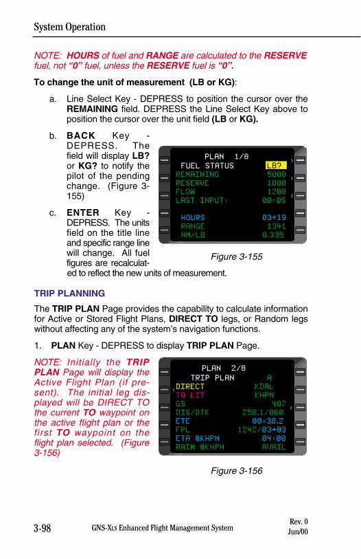
System Operation
3-98 GNS-XLS Enhanced Flight Management SystemRev. 0
Jun/00
NOTE: HOURS of fuel and RANGE are calculated to the RESERVEfuel, not “0” fuel, unless the RESERVE fuel is “0”.
To change the unit of measurement (LB or KG):
a. Line Select Key - DEPRESS to position the cursor over theREMAINING field. DEPRESS the Line Select Key above toposition the cursor over the unit field (LB or KG).
b. BACK Key -DEPRESS. Thefield will display LB?or KG? to notify thepilot of the pendingchange. (Figure 3-155)
c. ENTER Key -DEPRESS. The unitsfield on the title lineand specific range linewill change. All fuelfigures are recalculat-ed to reflect the new units of measurement.
TRIP PLANNING
The TRIP PLAN Page provides the capability to calculate informationfor Active or Stored Flight Plans, DIRECT TO legs, or Random legswithout affecting any of the system’s navigation functions.
1. PLAN Key - DEPRESS to display TRIP PLAN Page.
NOTE: Initially the TRIPPLAN Page will display theActive Flight Plan (if pre-sent). The initial leg dis-played will be DIRECT TOthe current TO waypoint onthe active flight plan or thefirst TO waypoint on theflight plan selected. (Figure3-156)
PLAN 1/8
FUEL STATUS LB?
REMAINING 5000
RESERVE 1000
FLOW 1200
LAST INPUT: 00:05
HOURS 03+19
RANGE 1341
NM/LB 0.335
>
>
>
Figure 3-155
TRIP PLAN A
DIRECT KDAL
TO LIT KHPN
GS 407
DIS/DTK 258.1/060
ETE 00:38.2
FPL 1242/03+03
ETA @KHPN 04:00
RAIM @KHPN AVAIL
<
PLAN 2/8
<
Figure 3-156
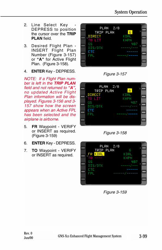
System Operation
3-99GNS-XLS Enhanced Flight Management SystemRev. 0Jun/00
2. Line Select Key -DEPRESS to positionthe cursor over the TRIPPLAN field.
3. Desired Flight Plan -INSERT Flight PlanNumber (Figure 3-157)or “A” for Active FlightPlan. (Figure 3-158).
4. ENTER Key - DEPRESS.
NOTE: If a Flight Plan num-ber is left in the TRIP PLANfield and not returned to “A”,no updated Active FlightPlan information will be dis-played. Figures 3-156 and 3-157 show how the screenappears when an Active FPLhas been selected and theairplane is airborne.
5. FR Waypoint - VERIFYor INSERT as required.(Figure 3-159)
6. ENTER Key - DEPRESS.
7. TO Waypoint - VERIFYor INSERT as required.
TRIP PLAN A
DIRECT KDAL
TO LIT KHPN
GS 407
DIS/DTK -----/---
ETE ------
FPL -----/-----
>
>
<
PLAN 2/8
Figure 3-158
TRIP PLAN 6
DIRECT KDAL
TO LIT KHPN
GS 407
DIS/DTK -----/---
ETE ------
FPL -----/-----
>
>
<
PLAN 2/8
Figure 3-157
TRIP PLAN 6
FR KDAL KDAL
TO ---- KHPN
GS 407
DIS/DTK -----/---
ETE ------
FPL ------/------
>
>
<
PLAN 2/8
Figure 3-159
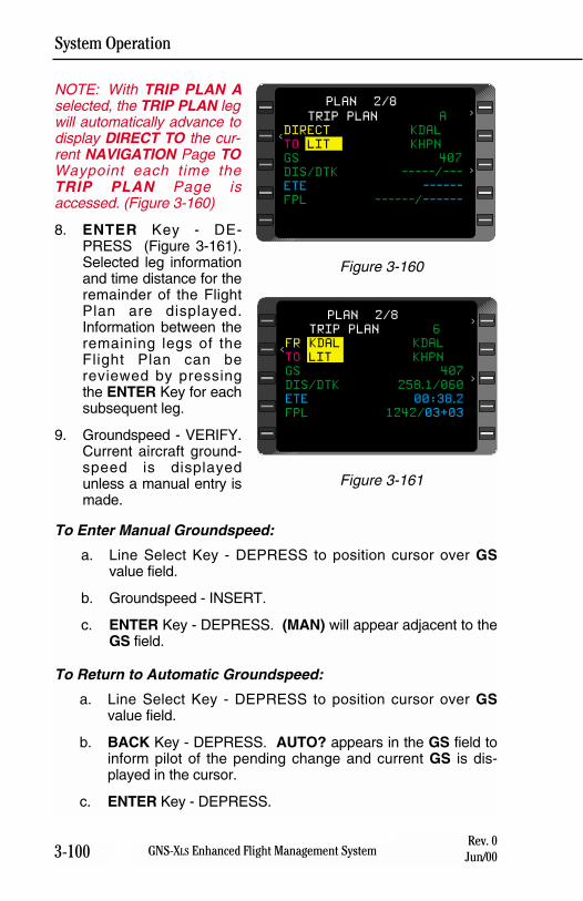
System Operation
3-100 GNS-XLS Enhanced Flight Management SystemRev. 0
Jun/00
NOTE: With TRIP PLAN Aselected, the TRIP PLAN legwill automatically advance todisplay DIRECT TO the cur-rent NAVIGATION Page TOWaypoint each time theTRIP PLAN Page isaccessed. (Figure 3-160)
8. ENTER Key - DE-PRESS (Figure 3-161).Selected leg informationand time distance for theremainder of the FlightPlan are displayed.Information between theremaining legs of theFlight Plan can bereviewed by pressingthe ENTER Key for eachsubsequent leg.
9. Groundspeed - VERIFY.Current aircraft ground-speed is displayedunless a manual entry ismade.
To Enter Manual Groundspeed:
a. Line Select Key - DEPRESS to position cursor over GSvalue field.
b. Groundspeed - INSERT.
c. ENTER Key - DEPRESS. (MAN) will appear adjacent to theGS field.
To Return to Automatic Groundspeed:
a. Line Select Key - DEPRESS to position cursor over GSvalue field.
b. BACK Key - DEPRESS. AUTO? appears in the GS field toinform pilot of the pending change and current GS is dis-played in the cursor.
c. ENTER Key - DEPRESS.
TRIP PLAN A
DIRECT KDAL
TO LIT KHPN
GS 407
DIS/DTK -----/---
ETE ------
FPL ------/------
>
>
<
PLAN 2/8
Figure 3-160
TRIP PLAN 6
FR KDAL KDAL
TO LIT KHPN
GS 407
DIS/DTK 258.1/060
ETE 00:38.2
FPL 1242/03+03
>
>
<
PLAN 2/8
Figure 3-161
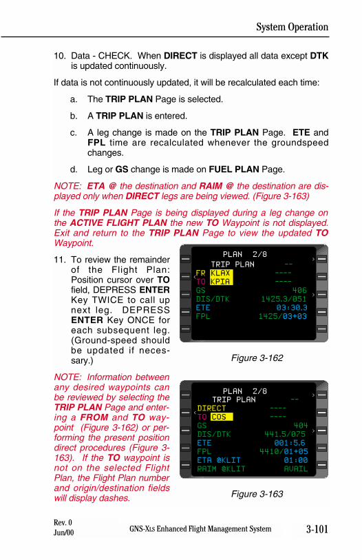
System Operation
3-101GNS-XLS Enhanced Flight Management SystemRev. 0Jun/00
10. Data - CHECK. When DIRECT is displayed all data except DTKis updated continuously.
If data is not continuously updated, it will be recalculated each time:
a. The TRIP PLAN Page is selected.
b. A TRIP PLAN is entered.
c. A leg change is made on the TRIP PLAN Page. ETE andFPL time are recalculated whenever the groundspeedchanges.
d. Leg or GS change is made on FUEL PLAN Page.
NOTE: ETA @ the destination and RAIM @ the destination are dis-played only when DIRECT legs are being viewed. (Figure 3-163)
If the TRIP PLAN Page is being displayed during a leg change onthe ACTIVE FLIGHT PLAN the new TO Waypoint is not displayed.Exit and return to the TRIP PLAN Page to view the updated TOWaypoint.
11. To review the remainderof the Flight Plan:Position cursor over TOfield, DEPRESS ENTERKey TWICE to call upnext leg. DEPRESSENTER Key ONCE foreach subsequent leg.(Ground-speed shouldbe updated if neces-sary.)
NOTE: Information betweenany desired waypoints canbe reviewed by selecting theTRIP PLAN Page and enter-ing a FROM and TO way-point (Figure 3-162) or per-forming the present positiondirect procedures (Figure 3-163). If the TO waypoint isnot on the selected FlightPlan, the Flight Plan numberand origin/destination fieldswill display dashes.
TRIP PLAN --
FR KLAX ----
TO KPIA ----
GS 406
DIS/DTK 1425.3/051
ETE 03:30.3
FPL 1425/03+03
>
>
<
PLAN 2/8
Figure 3-162
TRIP PLAN --
DIRECT ----
TO COS ----
GS 404
DIS/DTK 441.5/075
ETE 001:5.6
FPL 4410/01+05
ETA @KLIT 01:00
RAIM @KLIT AVAIL
>
>
<
PLAN 2/8
Figure 3-163
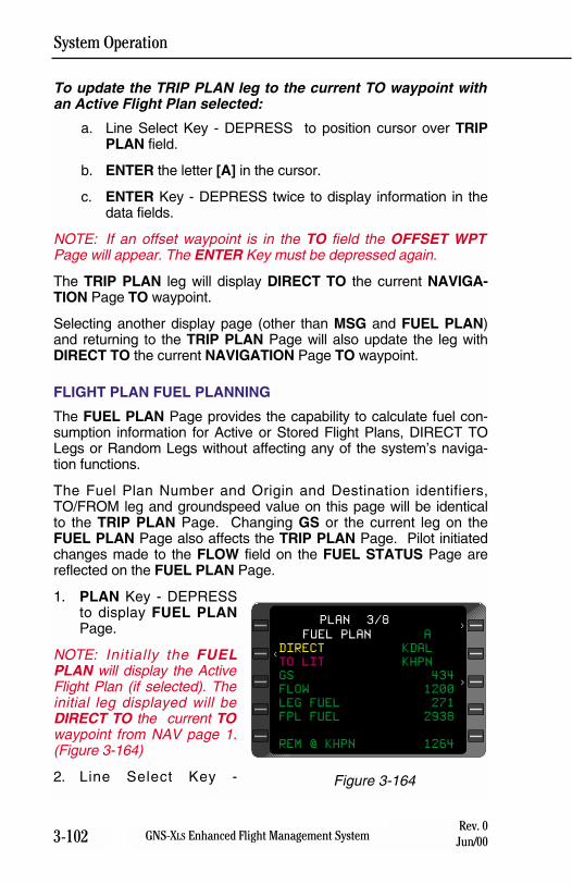
System Operation
3-102 GNS-XLS Enhanced Flight Management SystemRev. 0
Jun/00
To update the TRIP PLAN leg to the current TO waypoint withan Active Flight Plan selected:
a. Line Select Key - DEPRESS to position cursor over TRIPPLAN field.
b. ENTER the letter [A] in the cursor.
c. ENTER Key - DEPRESS twice to display information in thedata fields.
NOTE: If an offset waypoint is in the TO field the OFFSET WPTPage will appear. The ENTER Key must be depressed again.
The TRIP PLAN leg will display DIRECT TO the current NAVIGA-TION Page TO waypoint.
Selecting another display page (other than MSG and FUEL PLAN)and returning to the TRIP PLAN Page will also update the leg withDIRECT TO the current NAVIGATION Page TO waypoint.
FLIGHT PLAN FUEL PLANNING
The FUEL PLAN Page provides the capability to calculate fuel con-sumption information for Active or Stored Flight Plans, DIRECT TOLegs or Random Legs without affecting any of the system’s naviga-tion functions.
The Fuel Plan Number and Origin and Destination identifiers,TO/FROM leg and groundspeed value on this page will be identicalto the TRIP PLAN Page. Changing GS or the current leg on theFUEL PLAN Page also affects the TRIP PLAN Page. Pilot initiatedchanges made to the FLOW field on the FUEL STATUS Page arereflected on the FUEL PLAN Page.
1. PLAN Key - DEPRESSto display FUEL PLANPage.
NOTE: Initially the FUELPLAN will display the ActiveFlight Plan (if selected). Theinitial leg displayed will beDIRECT TO the current TOwaypoint from NAV page 1.(Figure 3-164)
2. Line Select Key -
FUEL PLAN A
DIRECT KDAL
TO LIT KHPN
GS 434
FLOW 1200
LEG FUEL 271
FPL FUEL 2938
REM @ KHPN 1264
>
>
<
PLAN 3/8
Figure 3-164
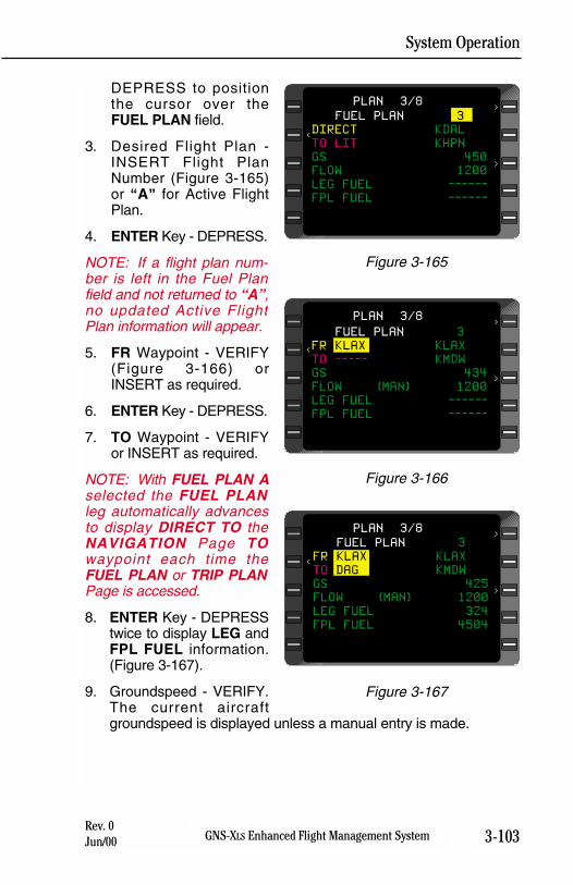
System Operation
3-103GNS-XLS Enhanced Flight Management SystemRev. 0Jun/00
DEPRESS to positionthe cursor over theFUEL PLAN field.
3. Desired Flight Plan -INSERT Flight PlanNumber (Figure 3-165)or “A” for Active FlightPlan.
4. ENTER Key - DEPRESS.
NOTE: If a flight plan num-ber is left in the Fuel Planfield and not returned to “A”,no updated Active FlightPlan information will appear.
5. FR Waypoint - VERIFY(Figure 3-166) orINSERT as required.
6. ENTER Key - DEPRESS.
7. TO Waypoint - VERIFYor INSERT as required.
NOTE: With FUEL PLAN Aselected the FUEL PLANleg automatically advancesto display DIRECT TO theNAVIGATION Page TOwaypoint each time theFUEL PLAN or TRIP PLANPage is accessed.
8. ENTER Key - DEPRESStwice to display LEG andFPL FUEL information.(Figure 3-167).
9. Groundspeed - VERIFY.The current aircraftgroundspeed is displayed unless a manual entry is made.
FUEL PLAN 3
DIRECT KDAL
TO LIT KHPN
GS 450
FLOW 1200
LEG FUEL ------
FPL FUEL ------
>
>PLAN 3/8
<
Figure 3-165
FUEL PLAN 3
FR KLAX KLAX
TO ----- KMDW
GS 434
FLOW (MAN) 1200
LEG FUEL ------
FPL FUEL ------
>
>PLAN 3/8
<
Figure 3-166
FUEL PLAN 3
FR KLAX KLAX
TO DAG KMDW
GS 425
FLOW (MAN) 1200
LEG FUEL 324
FPL FUEL 4504
>
>PLAN 3/8
<
Figure 3-167
System Operation
3-104 GNS-XLS Enhanced Flight Management SystemRev. 0
Jun/00
To Enter Manual Groundspeed:
a. Line Select Key - DEPRESS to position cursor over GS valuefield.
b. Groundspeed - INSERT.
c. ENTER Key - DEPRESS. (MAN) will appear adjacent to theGS field.
To Return To Automatic Groundspeed:
a. Line Select Key - DEPRESS to position cursor over GSvalue field.
b. BACK Key - DEPRESS. AUTO? appears in the GS field toinform pilot of the pending change and current GS is dis-played under the cursor.
c. ENTER Key - DEPRESS.
10. Fuel Flow - VERIFY. Current aircraft total fuel flow is displayedunless a manual entry is made.
To Enter A Manual Fuel Flow:
a. Line Select Key - DEPRESS to position cursor over FLOWvalue field.
b. Fuel Flow - INSERT.
c. ENTER Key - DEPRESS. (MAN) will appear adjacent to theFLOW field.
To Return to Automatic Fuel Flow:
a. Line Select Key -DEPRESS to position cursor over FLOWfield.
b. BACK Key - DEPRESS. AUTO? appears adjacent to theFLOW field to inform pilot of the pending change and currentflow is displayed under cursor.
c. ENTER Key- DEPRESS.
11. Data - CHECK. When DIRECT is displayed all data is continu-ously updated. If data is not continuously updated, it will be recal-culated each time:
a. The TRIP PLAN Page has changes in FR/TO leg or GS.
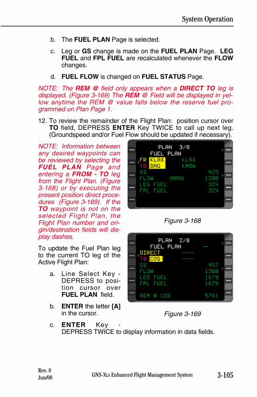
System Operation
3-105GNS-XLS Enhanced Flight Management SystemRev. 0Jun/00
b. The FUEL PLAN Page is selected.
c. Leg or GS change is made on the FUEL PLAN Page. LEGFUEL and FPL FUEL are recalculated whenever the FLOWchanges.
d. FUEL FLOW is changed on FUEL STATUS Page.
NOTE: The REM @ field only appears when a DIRECT TO leg isdisplayed. (Figure 3-169) The REM @ Field will be displayed in yel-low anytime the REM @ value falls below the reserve fuel pro-grammed on Plan Page 1.
12. To review the remainder of the Flight Plan: position cursor overTO field, DEPRESS ENTER Key TWICE to call up next leg.(Groundspeed and/or Fuel Flow should be updated if necessary).
NOTE: Information betweenany desired waypoints canbe reviewed by selecting theFUEL PLAN Page andentering a FROM - TO legfrom the Flight Plan. (Figure3-168) or by executing thepresent position direct proce-dures (Figure 3-169). If theTO waypoint is not on theselected Flight Plan, theFlight Plan number and ori-gin/destination fields will dis-play dashes.
To update the Fuel Plan legto the current TO leg of theActive Flight Plan:
a. Line Select Key -DEPRESS to posi-tion cursor overFUEL PLAN field.
b. ENTER the letter [A]in the cursor.
c. ENTER Key -DEPRESS TWICE to display information in data fields.
FUEL PLAN
FR KLAX KLAX
TO DAG KMDW
GS 425
FLOW (MAN) 1200
LEG FUEL 324
FPL FUEL 324
>
>PLAN 3/8
<
Figure 3-168
FUEL PLAN --
DIRECT ----
TO COS ----
GS 457
FLOW 1300
LEG FUEL 1679
FPL FUEL 1679
REM @ COS 5761
>
>
<
PLAN 2/8
Figure 3-169
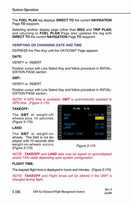
System Operation
3-106 GNS-XLS Enhanced Flight Management SystemRev. 0
Jun/00
The FUEL PLAN leg displays DIRECT TO the current NAVIGATIONPage TO waypoint.
Selecting another display page (other than MSG and TRIP PLAN)and returning to FUEL PLAN Page also updates the leg withDIRECT TO the current NAVIGATION Page TO waypoint.
VERIFYING OR CHANGING DATE AND TIME
DEPRESS the Plan Key until the DATE/GMT Page appears
DATE:
VERIFY or INSERT
Position cursor with Line Select Key and follow procedure in INITIAL-IZATION PAGE section.
GMT:
VERIFY or INSERT
Position cursor with Line Select Key and follow procedure in INITIAL-IZATION PAGE section.
NOTE: If GPS time is available, GMT is automatically updated toGPS time. (Figure 3-170)
TAKEOFF:
The GMT at weight-off-wheels plus 10 seconds.(Figure 3-170)
LAND:
The GMT at weight-on-wheels. This field is not dis-played until 10 seconds afterweight-on-wheels occurs.(Figure 3-170)
NOTE: TAKEOFF and LAND data may be based on groundspeedand/or TAS valids depending upon system configuration.
FLIGHT TIME:
The elapsed flight time is displayed in hours and minutes. (Figure 3-170)
NOTE: TAKEOFF and Flight times will be altered if the GMT ischanged during flight.
DATE 18 FEB 95
GMT 14:13
TAKEOFF 20:43
LAND 22:45
FLIGHT TIME 02+02
>
PLAN 5/8
Figure 3-170
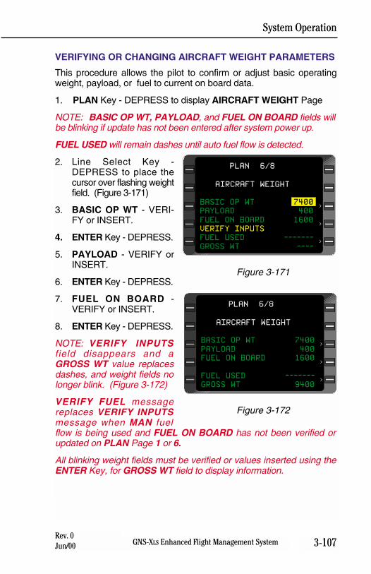
System Operation
3-107GNS-XLS Enhanced Flight Management SystemRev. 0Jun/00
VERIFYING OR CHANGING AIRCRAFT WEIGHT PARAMETERS
This procedure allows the pilot to confirm or adjust basic operatingweight, payload, or fuel to current on board data.
1. PLAN Key - DEPRESS to display AIRCRAFT WEIGHT Page
NOTE: BASIC OP WT, PAYLOAD, and FUEL ON BOARD fields willbe blinking if update has not been entered after system power up.
FUEL USED will remain dashes until auto fuel flow is detected.
2. Line Select Key -DEPRESS to place thecursor over flashing weightfield. (Figure 3-171)
3. BASIC OP WT - VERI-FY or INSERT.
4. ENTER Key - DEPRESS.
5. PAYLOAD - VERIFY orINSERT.
6. ENTER Key - DEPRESS.
7. FUEL ON BOARD -VERIFY or INSERT.
8. ENTER Key - DEPRESS.
NOTE: VERIFY INPUTSfield disappears and aGROSS WT value replacesdashes, and weight fields nolonger blink. (Figure 3-172)
VERIFY FUEL messagereplaces VERIFY INPUTSmessage when MAN fuelflow is being used and FUEL ON BOARD has not been verified orupdated on PLAN Page 1 or 6.
All blinking weight fields must be verified or values inserted using theENTER Key, for GROSS WT field to display information.
>
PLAN 6/8
>
AIRCRAFT WEIGHT
BASIC OP WT 7400
PAYLOAD 400
FUEL ON BOARD 1600
VERIFY INPUTS
FUEL USED -------
GROSS WT ---->
Figure 3-171
AIRCRAFT WEIGHT
BASIC OP WT 7400
PAYLOAD 400
FUEL ON BOARD 1600
FUEL USED -------
GROSS WT 9400
>
PLAN 6/8
>
>
Figure 3-172
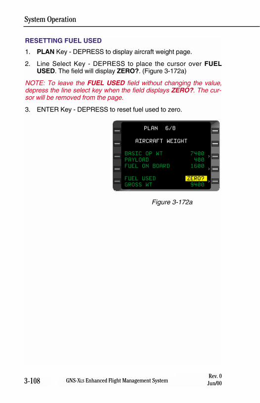
System Operation
3-108 GNS-XLS Enhanced Flight Management SystemRev. 0
Jun/00
RESETTING FUEL USED
1. PLAN Key - DEPRESS to display aircraft weight page.
2. Line Select Key - DEPRESS to place the cursor over FUELUSED. The field will display ZERO?. (Figure 3-172a)
NOTE: To leave the FUEL USED field without changing the value,depress the line select key when the field displays ZERO?. The cur-sor will be removed from the page.
3. ENTER Key - DEPRESS to reset fuel used to zero.
>
PLAN 6/8
>
>
AIRCRAFT WEIGHT
BASIC OP WT 7400
PAYLOAD 400
FUEL ON BOARD 1600
FUEL USED ZERO?
GROSS WT 9400
Figure 3-172a
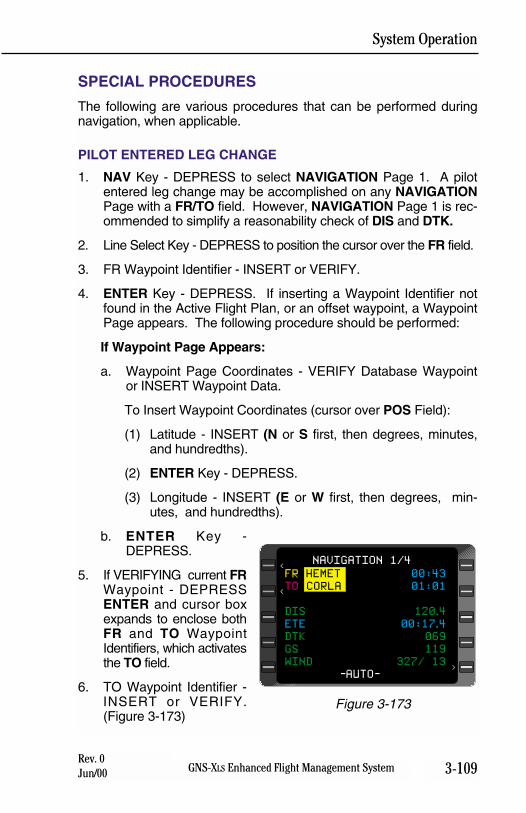
System Operation
3-109GNS-XLS Enhanced Flight Management SystemRev. 0Jun/00
SPECIAL PROCEDURES
The following are various procedures that can be performed duringnavigation, when applicable.
PILOT ENTERED LEG CHANGE
1. NAV Key - DEPRESS to select NAVIGATION Page 1. A pilotentered leg change may be accomplished on any NAVIGATIONPage with a FR/TO field. However, NAVIGATION Page 1 is rec-ommended to simplify a reasonability check of DIS and DTK.
2. Line Select Key - DEPRESS to position the cursor over the FR field.
3. FR Waypoint Identifier - INSERT or VERIFY.
4. ENTER Key - DEPRESS. If inserting a Waypoint Identifier notfound in the Active Flight Plan, or an offset waypoint, a WaypointPage appears. The following procedure should be performed:
If Waypoint Page Appears:
a. Waypoint Page Coordinates - VERIFY Database Waypointor INSERT Waypoint Data.
To Insert Waypoint Coordinates (cursor over POS Field):
(1) Latitude - INSERT (N or S first, then degrees, minutes,and hundredths).
(2) ENTER Key - DEPRESS.
(3) Longitude - INSERT (E or W first, then degrees, min-utes, and hundredths).
b. ENTER Key -DEPRESS.
5. If VERIFYING current FRWaypoint - DEPRESSENTER and cursor boxexpands to enclose bothFR and TO WaypointIdentifiers, which activatesthe TO field.
6. TO Waypoint Identifier -INSERT or VERIFY.(Figure 3-173)
FR HEMET 00:43
TO CORLA 01:01
DIS 120.4
ETE 00:17.4
DTK 069
GS 119
WIND 327/ 13
-AUTO-
NAVIGATION 1/4<
<
>
Figure 3-173
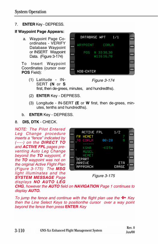
System Operation
3-110 GNS-XLS Enhanced Flight Management SystemRev. 0
Jun/00
7. ENTER Key - DEPRESS.
If Waypoint Page Appears:
a. Waypoint Page Co-ordinates - VERIFYDatabase Waypointor INSERT WaypointData. (Figure 3-174)
To Insert WaypointCoordinates (cursor overPOS Field):
(1) Latitude - IN-SERT (N or Sfirst, then de-grees, minutes, and hundredths).
(2) ENTER Key - DEPRESS.
(3) Longitude - IN-SERT (E or W first, then de-grees, min-utes, tenths and hundredths).
b. ENTER Key - DEPRESS.
8. DIS, DTK - CHECK.
NOTE: The Pilot EnteredLeg Change procedureinserts a “fence” indicated by(----) on the DIRECT TOand ACTIVE FPL pages pre-venting Auto Leg Changebeyond the TO waypoint, ifthe TO waypoint was not onthe original Active Flight Plan(Figure 3-175) The MSGl ight il luminates and theSYSTEM MESSAGE Pagedisplays NO AUTO LEGCHG, however the AUTO field on NAVIGATION Page 1 continues todisplay AUTO.
To jump the fence and continue with the flight plan use the d Keythen the Line Select Keys to positionthe cursor over a way pointbeyond the fence then press ENTER Key
WAYPOINT CORLA
POS N 33 38.30
W116 16.70
NDB-ENTER
DATABASE WPT 1/1
Figure 3-174
<
<
<
<
FR HEMET 7
TO CORLA 00:20 8
------
KSNA -KDTW
MUSEL
HEMET
DEPART
ARRIVE ETA
APPROACH ERASE>
>
ACTIVE FPL 1/2
>
Figure 3-175
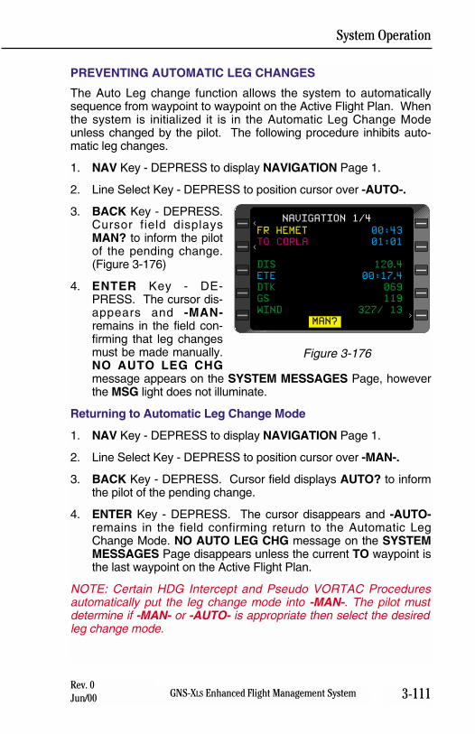
System Operation
3-111GNS-XLS Enhanced Flight Management SystemRev. 0Jun/00
PREVENTING AUTOMATIC LEG CHANGES
The Auto Leg change function allows the system to automaticallysequence from waypoint to waypoint on the Active Flight Plan. Whenthe system is initialized it is in the Automatic Leg Change Modeunless changed by the pilot. The following procedure inhibits auto-matic leg changes.
1. NAV Key - DEPRESS to display NAVIGATION Page 1.
2. Line Select Key - DEPRESS to position cursor over -AUTO-.
3. BACK Key - DEPRESS.Cursor field displaysMAN? to inform the pilotof the pending change.(Figure 3-176)
4. ENTER Key - DE-PRESS. The cursor dis-appears and -MAN-remains in the field con-firming that leg changesmust be made manually.NO AUTO LEG CHGmessage appears on the SYSTEM MESSAGES Page, howeverthe MSG light does not illuminate.
Returning to Automatic Leg Change Mode
1. NAV Key - DEPRESS to display NAVIGATION Page 1.
2. Line Select Key - DEPRESS to position cursor over -MAN-.
3. BACK Key - DEPRESS. Cursor field displays AUTO? to informthe pilot of the pending change.
4. ENTER Key - DEPRESS. The cursor disappears and -AUTO-remains in the field confirming return to the Automatic LegChange Mode. NO AUTO LEG CHG message on the SYSTEMMESSAGES Page disappears unless the current TO waypoint isthe last waypoint on the Active Flight Plan.
NOTE: Certain HDG Intercept and Pseudo VORTAC Proceduresautomatically put the leg change mode into -MAN-. The pilot mustdetermine if -MAN- or -AUTO- is appropriate then select the desiredleg change mode.
FR HEMET 00:43
TO CORLA 01:01
DIS 120.4
ETE 00:17.4
DTK 069
GS 119
WIND 327/ 13
MAN?
NAVIGATION 1/4<
<
>
Figure 3-176
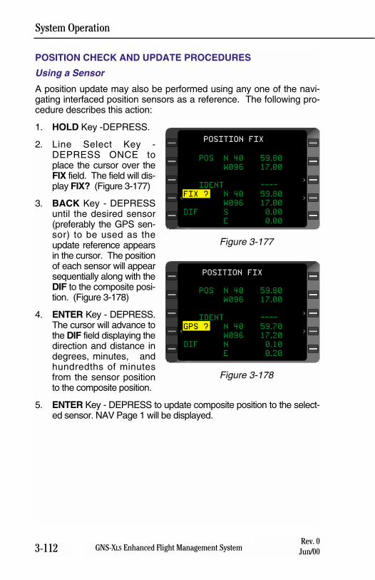
System Operation
3-112 GNS-XLS Enhanced Flight Management SystemRev. 0
Jun/00
POSITION CHECK AND UPDATE PROCEDURES
Using a Sensor
A position update may also be performed using any one of the navi-gating interfaced position sensors as a reference. The following pro-cedure describes this action:
1. HOLD Key -DEPRESS.
2. Line Select Key -DEPRESS ONCE toplace the cursor over theFIX field. The field will dis-play FIX? (Figure 3-177)
3. BACK Key - DEPRESSuntil the desired sensor(preferably the GPS sen-sor) to be used as theupdate reference appearsin the cursor. The positionof each sensor will appearsequentially along with theDIF to the composite posi-tion. (Figure 3-178)
4. ENTER Key - DEPRESS.The cursor will advance tothe DIF field displaying thedirection and distance indegrees, minutes, andhundredths of minutesfrom the sensor positionto the composite position.
5. ENTER Key - DEPRESS to update composite position to the select-ed sensor. NAV Page 1 will be displayed.
POS N 40 59.80
W096 17.00
IDENT ----
FIX ? N 40 59.80
W096 17.00
DIF S 0.00
E 0.00
POSITION FIX
>
>
<
Figure 3-177
POS N 40 59.80
W096 17.00
IDENT ----
GPS ? N 40 59.70
W096 17.20
DIF N 0.10
E 0.20
POSITION FIX
>
>
<
Figure 3-178
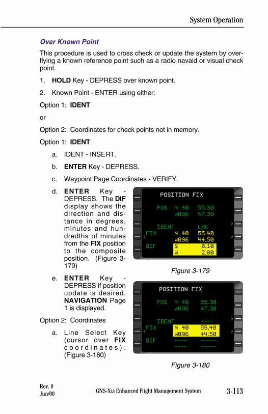
System Operation
3-113GNS-XLS Enhanced Flight Management SystemRev. 0Jun/00
Over Known Point
This procedure is used to cross check or update the system by over-flying a known reference point such as a radio navaid or visual checkpoint.
1. HOLD Key - DEPRESS over known point.
2. Known Point - ENTER using either:
Option 1: IDENT
or
Option 2: Coordinates for check points not in memory.
Option 1: IDENT
a. IDENT - INSERT.
b. ENTER Key - DEPRESS.
c. Waypoint Page Coordinates - VERIFY.
d. ENTER Key -DEPRESS. The DIFdisplay shows thedirection and dis-tance in degrees,minutes and hun-dredths of minutesfrom the FIX positionto the compositeposition. (Figure 3-179)
e. ENTER Key -DEPRESS if positionupdate is desired.NAVIGATION Page1 is displayed.
Option 2: Coordinates
a. Line Select Key(cursor over FIXc o o r d i n a t e s ) .(Figure 3-180)
POS N 40 55.30
W096 47.30
IDENT LNK
FIX N 40 55.40
W096 44.50
DIF S 0.10
W 2.80
POSITION FIX
>
>
<
Figure 3-179
POS N 40 55.30
W096 47.30
IDENT ----
FIX N 40 55.40
W096 44.50
DIF ---- -----
---- -----
POSITION FIX
>
>
<
Figure 3-180
System Operation
3-114 GNS-XLS Enhanced Flight Management SystemRev. 0
Jun/00
b. Latitude - INSERT (N or S first, then degrees, minutes, andhundredths).
c. ENTER Key - DEPRESS.
d. Longitude - INSERT (E or W first, then degrees, minutes,and hundredths).
e. ENTER Key - DEPRESS.
The DIF display shows the direction and distance in degrees,minutes and hundredths of minutes from the FIX position tothe composite position.
f. ENTER Key - DEPRESS if position update is desired. NAVI-GATION Page 1 is displayed
NOTE: If coordinate field flashes after entry, verify coordinates anddepress ENTER again.
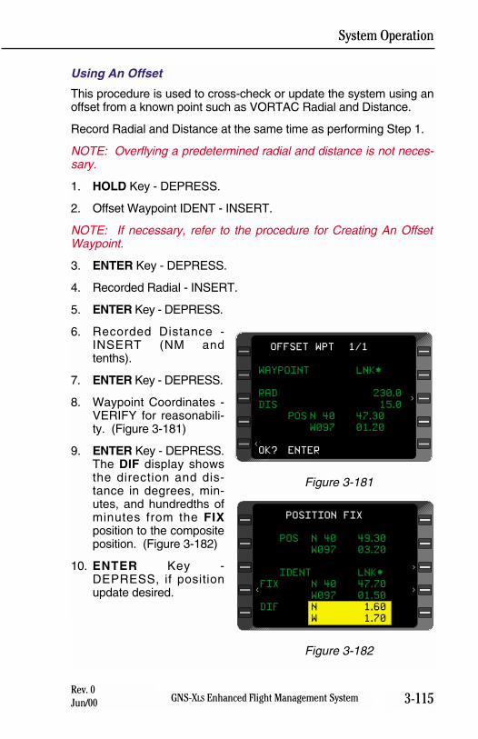
System Operation
3-115GNS-XLS Enhanced Flight Management SystemRev. 0Jun/00
Using An Offset
This procedure is used to cross-check or update the system using anoffset from a known point such as VORTAC Radial and Distance.
Record Radial and Distance at the same time as performing Step 1.
NOTE: Overflying a predetermined radial and distance is not neces-sary.
1. HOLD Key - DEPRESS.
2. Offset Waypoint IDENT - INSERT.
NOTE: If necessary, refer to the procedure for Creating An OffsetWaypoint.
3. ENTER Key - DEPRESS.
4. Recorded Radial - INSERT.
5. ENTER Key - DEPRESS.
6. Recorded Distance -INSERT (NM andtenths).
7. ENTER Key - DEPRESS.
8. Waypoint Coordinates -VERIFY for reasonabili-ty. (Figure 3-181)
9. ENTER Key - DEPRESS.The DIF display showsthe direction and dis-tance in degrees, min-utes, and hundredths ofminutes from the FIXposition to the compositeposition. (Figure 3-182)
10. ENTER Key -DEPRESS, if positionupdate desired.
POS N 40 49.30
W097 03.20
IDENT LNK*
FIX N 40 47.70
W097 01.50
DIF N 1.60
W 1.70
POSITION FIX
>
>
<
Figure 3-182
WAYPOINT LNK*
RAD 230.0
DIS 15.0
POS N 40 47.30
W097 01.20
OK? ENTER
OFFSET WPT 1/1
>
<
Figure 3-181
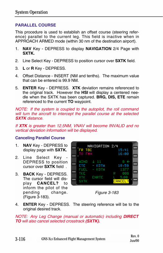
System Operation
3-116 GNS-XLS Enhanced Flight Management SystemRev. 0
Jun/00
PARALLEL COURSE
This procedure is used to establish an offset course (steering refer-ence) parallel to the current leg. This field is inactive when inAPPROACH ARMED mode (within 30 nm of the destination airport).
1. NAV Key - DEPRESS to display NAVIGATION 2/4 Page withSXTK.
2. Line Select Key - DEPRESS to position cursor over SXTK field.
3. L or R Key - DEPRESS.
4. Offset Distance - INSERT (NM and tenths). The maximum valuethat can be entered is 99.9 NM.
5. ENTER Key - DEPRESS. XTK deviation remains referenced tothe original track. However the HSI will display a centered nee-dle when the SXTK has been captured. BRG, DIS, ETE remainreferenced to the current TO waypoint.
NOTE: If the system is coupled to the autopilot, the roll commandwill turn the aircraft to intercept the parallel course at the selectedSXTK distance.
If XTK is greater than 12.5NM, VNAV will become INVALID and novertical deviation information will be displayed.
Canceling Parallel Course
1. NAV Key - DEPRESS todisplay page with SXTK.
2. Line Select Key -DEPRESS to positioncursor over SXTK field .
3. BACK Key - DEPRESS.The cursor field will dis-play CANCEL? toinform the pilot of thepending change.(Figure 3-183).
4. ENTER Key - DEPRESS. The steering reference will be to theoriginal desired track.
NOTE: Any Leg Change (manual or automatic) including DIRECTTO will also cancel selected crosstrack (SXTK).
FR TBC 15:41
TO FMN 16:00
WIND % 11 8 &
ETE - KDTW 18:59
FUEL - KDTW 1377
TKE R 008
XTK ENRTE L 5.00
SXTK CANCEL?
NAVIGATION 2/4<
<
>
Figure 3-183
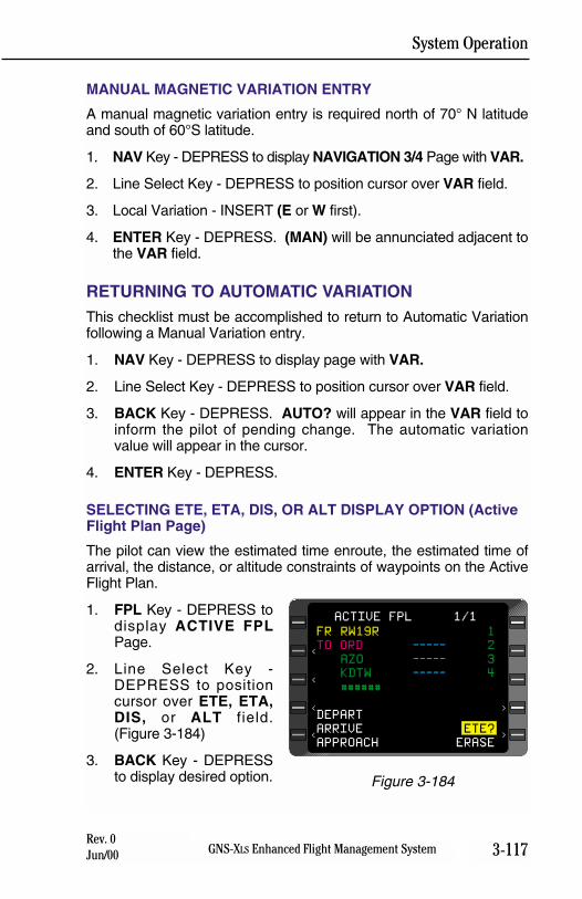
System Operation
3-117GNS-XLS Enhanced Flight Management SystemRev. 0Jun/00
MANUAL MAGNETIC VARIATION ENTRY
A manual magnetic variation entry is required north of 70° N latitudeand south of 60°S latitude.
1. NAV Key - DEPRESS to display NAVIGATION 3/4 Page with VAR.
2. Line Select Key - DEPRESS to position cursor over VAR field.
3. Local Variation - INSERT (E or W first).
4. ENTER Key - DEPRESS. (MAN) will be annunciated adjacent tothe VAR field.
RETURNING TO AUTOMATIC VARIATIONThis checklist must be accomplished to return to Automatic Variationfollowing a Manual Variation entry.
1. NAV Key - DEPRESS to display page with VAR.
2. Line Select Key - DEPRESS to position cursor over VAR field.
3. BACK Key - DEPRESS. AUTO? will appear in the VAR field toinform the pilot of pending change. The automatic variationvalue will appear in the cursor.
4. ENTER Key - DEPRESS.
SELECTING ETE, ETA, DIS, OR ALT DISPLAY OPTION (ActiveFlight Plan Page)
The pilot can view the estimated time enroute, the estimated time ofarrival, the distance, or altitude constraints of waypoints on the ActiveFlight Plan.
1. FPL Key - DEPRESS todisplay ACTIVE FPLPage.
2. Line Select Key -DEPRESS to positioncursor over ETE, ETA,DIS, or ALT field.(Figure 3-184)
3. BACK Key - DEPRESSto display desired option.
<
<
<
<
FR RW19R 1
TO ORD ----- 2
AZO ----- 3
KDTW ----- 4
######
DEPART
ARRIVE ETE?
APPROACH ERASE>
>
ACTIVE FPL 1/1
Figure 3-184
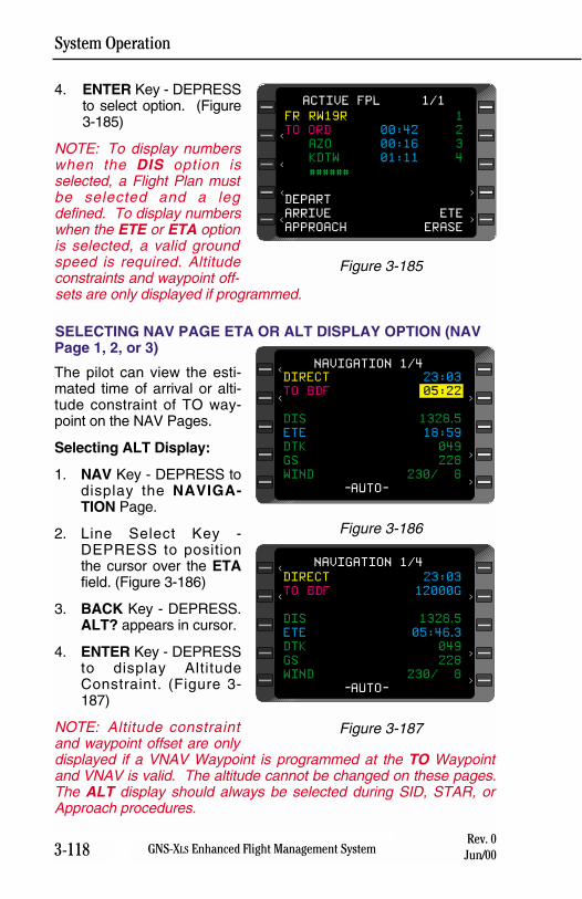
System Operation
3-118 GNS-XLS Enhanced Flight Management SystemRev. 0
Jun/00
4. ENTER Key - DEPRESSto select option. (Figure3-185)
NOTE: To display numberswhen the DIS option isselected, a Flight Plan mustbe selected and a legdefined. To display numberswhen the ETE or ETA optionis selected, a valid groundspeed is required. Altitudeconstraints and waypoint off-sets are only displayed if programmed.
SELECTING NAV PAGE ETA OR ALT DISPLAY OPTION (NAVPage 1, 2, or 3)
The pilot can view the esti-mated time of arrival or alti-tude constraint of TO way-point on the NAV Pages.
Selecting ALT Display:
1. NAV Key - DEPRESS todisplay the NAVIGA-TION Page.
2. Line Select Key -DEPRESS to positionthe cursor over the ETAfield. (Figure 3-186)
3. BACK Key - DEPRESS.ALT? appears in cursor.
4. ENTER Key - DEPRESSto display AltitudeConstraint. (Figure 3-187)
NOTE: Altitude constraintand waypoint offset are onlydisplayed if a VNAV Waypoint is programmed at the TO Waypointand VNAV is valid. The altitude cannot be changed on these pages.The ALT display should always be selected during SID, STAR, orApproach procedures.
<
<
<
<
FR RW19R 1
TO ORD 00:42 2
AZO 00:16 3
KDTW 01:11 4
######
DEPART
ARRIVE ETE
APPROACH ERASE>
>
ACTIVE FPL 1/1
Figure 3-185
DIRECT 23:03
TO BDF 05:22
DIS 1328.5
ETE 18:59
DTK 049
GS 228
WIND 230/ 8
-AUTO-
NAVIGATION 1/4<
<
>
>
>
Figure 3-186
DIRECT 23:03
TO BDF 12000G
DIS 1328.5
ETE 05:46.3
DTK 049
GS 228
WIND 230/ 8
-AUTO-
NAVIGATION 1/4<
<
>
>
>
Figure 3-187
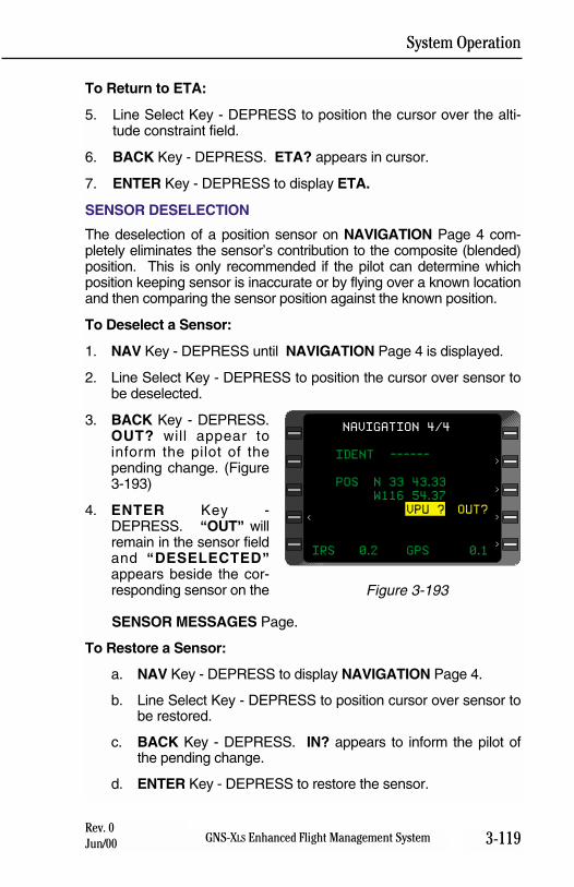
System Operation
3-119GNS-XLS Enhanced Flight Management SystemRev. 0Jun/00
To Return to ETA:
5. Line Select Key - DEPRESS to position the cursor over the alti-tude constraint field.
6. BACK Key - DEPRESS. ETA? appears in cursor.
7. ENTER Key - DEPRESS to display ETA.
SENSOR DESELECTION
The deselection of a position sensor on NAVIGATION Page 4 com-pletely eliminates the sensor’s contribution to the composite (blended)position. This is only recommended if the pilot can determine whichposition keeping sensor is inaccurate or by flying over a known locationand then comparing the sensor position against the known position.
To Deselect a Sensor:
1. NAV Key - DEPRESS until NAVIGATION Page 4 is displayed.
2. Line Select Key - DEPRESS to position the cursor over sensor tobe deselected.
3. BACK Key - DEPRESS.OUT? will appear toinform the pilot of thepending change. (Figure3-193)
4. ENTER Key -DEPRESS. “OUT” willremain in the sensor fieldand “DESELECTED”appears beside the cor-responding sensor on the
SENSOR MESSAGES Page.
To Restore a Sensor:
a. NAV Key - DEPRESS to display NAVIGATION Page 4.
b. Line Select Key - DEPRESS to position cursor over sensor tobe restored.
c. BACK Key - DEPRESS. IN? appears to inform the pilot ofthe pending change.
d. ENTER Key - DEPRESS to restore the sensor.
IDENT ------
POS N 33 43.33
W116 54.37
VPU ? OUT?
IRS 0.2 GPS 0.1
NAVIGATION 4/4
<
>
>
>
>
Figure 3-193
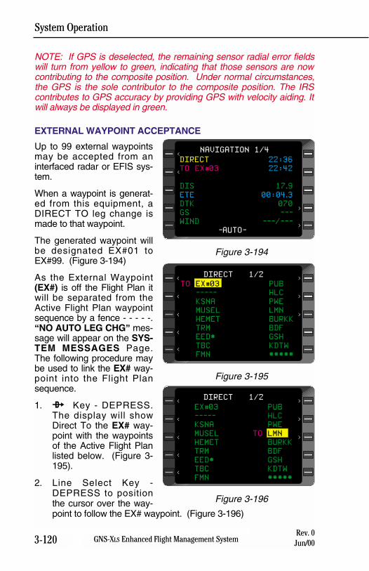
System Operation
3-120 GNS-XLS Enhanced Flight Management SystemRev. 0
Jun/00
NOTE: If GPS is deselected, the remaining sensor radial error fieldswill turn from yellow to green, indicating that those sensors are nowcontributing to the composite position. Under normal circumstances,the GPS is the sole contributor to the composite position. The IRScontributes to GPS accuracy by providing GPS with velocity aiding. Itwill always be displayed in green.
EXTERNAL WAYPOINT ACCEPTANCE
Up to 99 external waypointsmay be accepted from aninterfaced radar or EFIS sys-tem.
When a waypoint is generat-ed from this equipment, aDIRECT TO leg change ismade to that waypoint.
The generated waypoint willbe designated EX#01 toEX#99. (Figure 3-194)
As the External Waypoint(EX#) is off the Flight Plan itwill be separated from theActive Flight Plan waypointsequence by a fence - - - - -.“NO AUTO LEG CHG” mes-sage will appear on the SYS-TEM MESSAGES Page.The following procedure maybe used to link the EX# way-point into the Flight Plansequence.
1. d Key - DEPRESS.The display will showDirect To the EX# way-point with the waypointsof the Active Flight Planlisted below. (Figure 3-195).
2. Line Select Key -DEPRESS to positionthe cursor over the way-point to follow the EX# waypoint. (Figure 3-196)
EX#03 PUB
----- HLC
KSNA PWE
MUSEL TO LMN
HEMET BURKK
TRM BDF
EED* GSH
TBC KDTW
FMN *****
DIRECT 1/2
>
>
>
<
<
<
<
<
Figure 3-196
DIRECT 22:36
TO EX#03 22:42
DIS 17.9
ETE 00:04.3
DTK 070
GS ---
WIND ---/---
-AUTO-
NAVIGATION 1/4<
<
>
>
Figure 3-194
TO EX#03 PUB
----- HLC
KSNA PWE
MUSEL LMN
HEMET BURKK
TRM BDF
EED* GSH
TBC KDTW
FMN *****
DIRECT 1/2
>
>
>
<
<
<
<
<
Figure 3-195
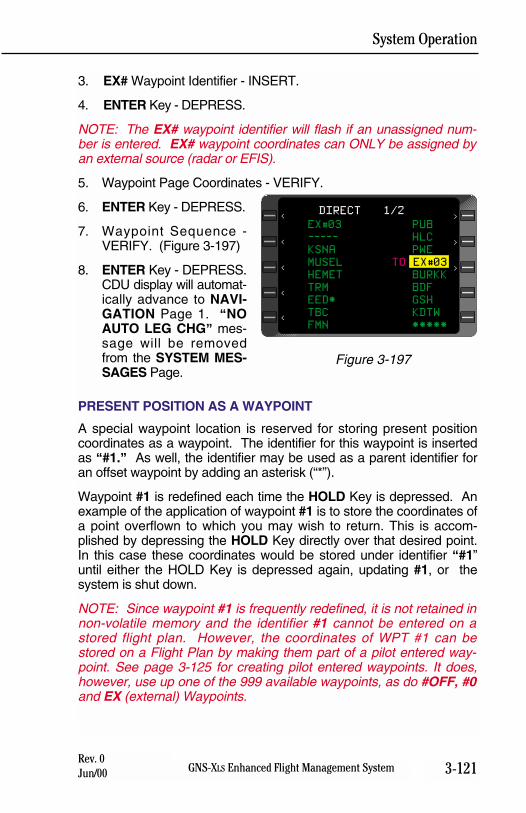
System Operation
3-121GNS-XLS Enhanced Flight Management SystemRev. 0Jun/00
3. EX# Waypoint Identifier - INSERT.
4. ENTER Key - DEPRESS.
NOTE: The EX# waypoint identifier will flash if an unassigned num-ber is entered. EX# waypoint coordinates can ONLY be assigned byan external source (radar or EFIS).
5. Waypoint Page Coordinates - VERIFY.
6. ENTER Key - DEPRESS.
7. Waypoint Sequence -VERIFY. (Figure 3-197)
8. ENTER Key - DEPRESS.CDU display will automat-ically advance to NAVI-GATION Page 1. “NOAUTO LEG CHG” mes-sage will be removedfrom the SYSTEM MES-SAGES Page.
PRESENT POSITION AS A WAYPOINT
A special waypoint location is reserved for storing present positioncoordinates as a waypoint. The identifier for this waypoint is insertedas “#1.” As well, the identifier may be used as a parent identifier foran offset waypoint by adding an asterisk (“*”).
Waypoint #1 is redefined each time the HOLD Key is depressed. Anexample of the application of waypoint #1 is to store the coordinates ofa point overflown to which you may wish to return. This is accom-plished by depressing the HOLD Key directly over that desired point.In this case these coordinates would be stored under identifier “#1”until either the HOLD Key is depressed again, updating #1, or thesystem is shut down.
NOTE: Since waypoint #1 is frequently redefined, it is not retained innon-volatile memory and the identifier #1 cannot be entered on astored flight plan. However, the coordinates of WPT #1 can bestored on a Flight Plan by making them part of a pilot entered way-point. See page 3-125 for creating pilot entered waypoints. It does,however, use up one of the 999 available waypoints, as do #OFF, #0and EX (external) Waypoints.
EX#03 PUB
----- HLC
KSNA PWE
MUSEL TO EX#03
HEMET BURKK
TRM BDF
EED* GSH
TBC KDTW
FMN *****
DIRECT 1/2
>
>
>
<
<
<
<
<
Figure 3-197
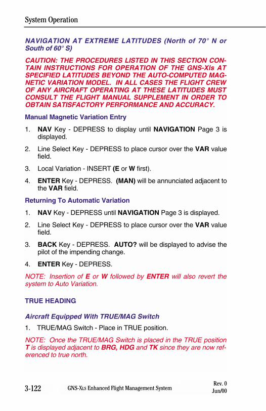
System Operation
3-122 GNS-XLS Enhanced Flight Management SystemRev. 0
Jun/00
NAVIGATION AT EXTREME LATITUDES (North of 70° N orSouth of 60° S)
CAUTION: THE PROCEDURES LISTED IN THIS SECTION CON-TAIN INSTRUCTIONS FOR OPERATION OF THE GNS-Xls ATSPECIFIED LATITUDES BEYOND THE AUTO-COMPUTED MAG-NETIC VARIATION MODEL. IN ALL CASES THE FLIGHT CREWOF ANY AIRCRAFT OPERATING AT THESE LATITUDES MUSTCONSULT THE FLIGHT MANUAL SUPPLEMENT IN ORDER TOOBTAIN SATISFACTORY PERFORMANCE AND ACCURACY.
Manual Magnetic Variation Entry
1. NAV Key - DEPRESS to display until NAVIGATION Page 3 isdisplayed.
2. Line Select Key - DEPRESS to place cursor over the VAR valuefield.
3. Local Variation - INSERT (E or W first).
4. ENTER Key - DEPRESS. (MAN) will be annunciated adjacent tothe VAR field.
Returning To Automatic Variation
1. NAV Key - DEPRESS until NAVIGATION Page 3 is displayed.
2. Line Select Key - DEPRESS to place cursor over the VAR valuefield.
3. BACK Key - DEPRESS. AUTO? will be displayed to advise thepilot of the impending change.
4. ENTER Key - DEPRESS.
NOTE: Insertion of E or W followed by ENTER will also revert thesystem to Auto Variation.
TRUE HEADING
Aircraft Equipped With TRUE/MAG Switch
1. TRUE/MAG Switch - Place in TRUE position.
NOTE: Once the TRUE/MAG Switch is placed in the TRUE positionT is displayed adjacent to BRG, HDG and TK since they are now ref-erenced to true north.
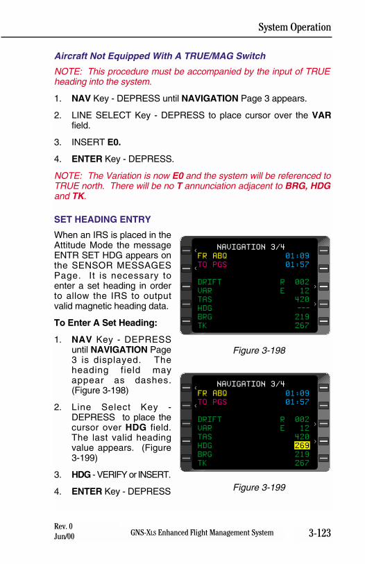
System Operation
3-123GNS-XLS Enhanced Flight Management SystemRev. 0Jun/00
Aircraft Not Equipped With A TRUE/MAG Switch
NOTE: This procedure must be accompanied by the input of TRUEheading into the system.
1. NAV Key - DEPRESS until NAVIGATION Page 3 appears.
2. LINE SELECT Key - DEPRESS to place cursor over the VARfield.
3. INSERT E0.
4. ENTER Key - DEPRESS.
NOTE: The Variation is now E0 and the system will be referenced toTRUE north. There will be no T annunciation adjacent to BRG, HDGand TK.
SET HEADING ENTRY
When an IRS is placed in theAttitude Mode the messageENTR SET HDG appears onthe SENSOR MESSAGESPage. It is necessary toenter a set heading in orderto allow the IRS to outputvalid magnetic heading data.
To Enter A Set Heading:
1. NAV Key - DEPRESSuntil NAVIGATION Page3 is displayed. Theheading field mayappear as dashes.(Figure 3-198)
2. Line Select Key -DEPRESS to place thecursor over HDG field.The last valid headingvalue appears. (Figure3-199)
3. HDG - VERIFY or INSERT.
4. ENTER Key - DEPRESS
FR ABQ 01:09
TO PGS 01:57
DRIFT R 002
VAR E 12
TAS 420
HDG ---
BRG 219
TK 267
NAVIGATION 3/4<
<
>
>
Figure 3-198
FR ABQ 01:09
TO PGS 01:57
DRIFT R 002
VAR E 12
TAS 420
HDG 269
BRG 219
TK 267
NAVIGATION 3/4<
<
>
>
Figure 3-199
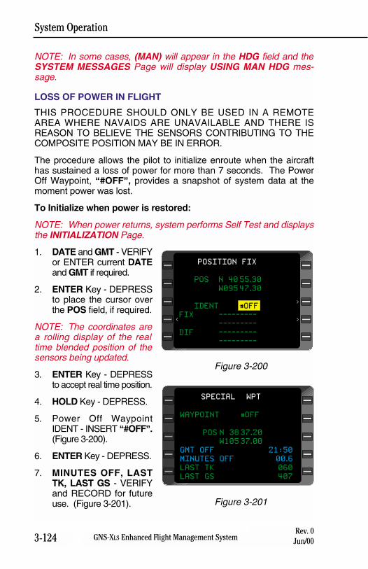
System Operation
3-124 GNS-XLS Enhanced Flight Management SystemRev. 0
Jun/00
NOTE: In some cases, (MAN) will appear in the HDG field and theSYSTEM MESSAGES Page will display USING MAN HDG mes-sage.
LOSS OF POWER IN FLIGHT
THIS PROCEDURE SHOULD ONLY BE USED IN A REMOTEAREA WHERE NAVAIDS ARE UNAVAILABLE AND THERE ISREASON TO BELIEVE THE SENSORS CONTRIBUTING TO THECOMPOSITE POSITION MAY BE IN ERROR.
The procedure allows the pilot to initialize enroute when the aircrafthas sustained a loss of power for more than 7 seconds. The PowerOff Waypoint, “#OFF”, provides a snapshot of system data at themoment power was lost.
To Initialize when power is restored:
NOTE: When power returns, system performs Self Test and displaysthe INITIALIZATION Page.
1. DATE and GMT - VERIFYor ENTER current DATEand GMT if required.
2. ENTER Key - DEPRESSto place the cursor overthe POS field, if required.
NOTE: The coordinates area rolling display of the realtime blended position of thesensors being updated.
3. ENTER Key - DEPRESSto accept real time position.
4. HOLD Key - DEPRESS.
5. Power Off WaypointIDENT - INSERT “#OFF”.(Figure 3-200).
6. ENTER Key - DEPRESS.
7. MINUTES OFF, LASTTK, LAST GS - VERIFYand RECORD for futureuse. (Figure 3-201).
POS N 40 55.30
W095 47.30
IDENT #OFF
FIX ---------
---------
DIF ---------
---------
POSITION FIX
>
>
<
Figure 3-200
WAYPOINT #OFF
POS N 38 37.20
W105 37.00
GMT OFF 21:50
MINUTES OFF 00.6
LAST TK 060
LAST GS 407
SPECIAL WPT
Figure 3-201
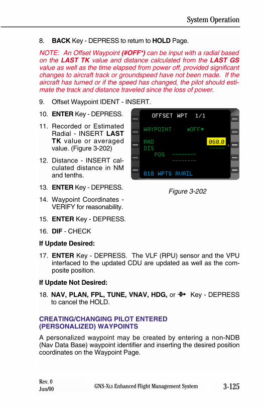
System Operation
3-125GNS-XLS Enhanced Flight Management SystemRev. 0Jun/00
8. BACK Key - DEPRESS to return to HOLD Page.
NOTE: An Offset Waypoint (#OFF*) can be input with a radial basedon the LAST TK value and distance calculated from the LAST GSvalue as well as the time elapsed from power off, provided significantchanges to aircraft track or groundspeed have not been made. If theaircraft has turned or if the speed has changed, the pilot should esti-mate the track and distance traveled since the loss of power.
9. Offset Waypoint IDENT - INSERT.
10. ENTER Key - DEPRESS.
11. Recorded or EstimatedRadial - INSERT LASTTK value or averagedvalue. (Figure 3-202)
12. Distance - INSERT cal-culated distance in NMand tenths.
13. ENTER Key - DEPRESS.
14. Waypoint Coordinates -VERIFY for reasonability.
15. ENTER Key - DEPRESS.
16. DIF - CHECK
If Update Desired:
17. ENTER Key - DEPRESS. The VLF (RPU) sensor and the VPUinterfaced to the updated CDU are updated as well as the com-posite position.
If Update Not Desired:
18. NAV, PLAN, FPL, TUNE, VNAV, HDG, or d Key - DEPRESSto cancel the HOLD.
CREATING/CHANGING PILOT ENTERED(PERSONALIZED) WAYPOINTS
A personalized waypoint may be created by entering a non-NDB(Nav Data Base) waypoint identifier and inserting the desired positioncoordinates on the Waypoint Page.
WAYPOINT #OFF*
RAD 060.0
DIS -----
POS --------
--------
818 WPTS AVAIL
OFFSET WPT 1/1
>
Figure 3-202
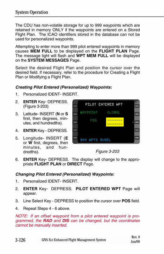
System Operation
3-126 GNS-XLS Enhanced Flight Management SystemRev. 0
Jun/00
The CDU has non-volatile storage for up to 999 waypoints which areretained in memory ONLY if the waypoints are entered on a StoredFlight Plan. The ICAO identifiers stored in the database can not beused for personalized waypoints.
Attempting to enter more than 999 pilot entered waypoints in memorycauses MEM FULL to be displayed on the FLIGHT PLAN Page.The message light will flash and WPT MEM FULL will be displayedon the SYSTEM MESSAGES Page.
Select the desired Flight Plan and position the cursor over thedesired field. If necessary, refer to the procedure for Creating a FlightPlan or Modifying a Flight Plan.
Creating Pilot Entered (Personalized) Waypoints:
1. Personalized IDENT- INSERT.
2. ENTER Key- DEPRESS.(Figure 3-203)
3. Latitude- INSERT (N or Sfirst, then degrees, min-utes, and hundredths).
4. ENTER Key - DEPRESS.
5. Longitude- INSERT (Eor W first, degrees, thenminutes, and hun-dredths).
6. ENTER Key- DEPRESS. The display will change to the appro-priate FLIGHT PLAN or DIRECT Page.
Changing Pilot Entered (Personalized) Waypoints:
1. Personalized IDENT- INSERT.
2. ENTER Key- DEPRESS. PILOT ENTERED WPT Page willappear.
3. Line Select Key - DEPRESS to position the cursor over POS field.
4. Repeat Steps 4 - 6 above.
NOTE: If an offset waypoint from a pilot entered waypoint is pro-grammed, the RAD and DIS can be changed, but the coordinatescannot be manually inserted.
WAYPOINT GLOBAL
POS --------
--------
944 WPTS AVAIL
PILOT ENTERED WPT
>
Figure 3-203
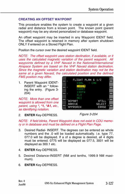
System Operation
3-127GNS-XLS Enhanced Flight Management SystemRev. 0Jun/00
CREATING AN OFFSET WAYPOINT
This procedure enables the system to create a waypoint at a givenradial and distance from a known point. The known point (parentwaypoint) may be any stored personalized or database waypoint.
An offset waypoint may be inserted in any Waypoint IDENT field.The offset waypoint is retained in memory after system shutdownONLY if entered on a Stored Flight Plan.
Position the cursor over the desired waypoint IDENT field.
NOTE: The offset waypoint uses station declination, if available, or ituses the calculated magnetic variation of the parent waypoint. Allwaypoints defined by a VHF Navaid in the National/InternationalAirspace System are based on the VHF Navaid station declination.Since the magnetic variation and station declination may not be thesame at a given Navaid, the calculated position and the definedFMS position may differ.
1. Parent Waypoint IDENT-INSERT with an * follow-ing the entry. (Figure 3-204)
NOTE: More than one offsetwaypoint is allowed from oneparent, using *, *1, *A1, etc.,as identifying notation.
2. ENTER Key-DEPRESS.
NOTE: If field blinks, Parent Waypoint does not exist in CDU memo-ry or in database and must be defined on a Flight Plan Page.
3. Desired Radial- INSERT. The degrees can be entered as wholenumbers and the .0 will be loaded automatically. i.e. type 77,077.0 will be displayed. If a of a degree is desired, all 4 digitsmust be entered. 0775 will be displayed as 077.5, 3001 will bedisplayed as 300.1 etc.
4. ENTER Key-DEPRESS.
5. Desired Distance-INSERT (NM and tenths, 1999.9 NM maxi-mum).
6. ENTER Key-DEPRESS.
KDAL - CMK
CHAD*
KHART
19DFW
ELD
MEI
DEPART XFILL
ARRIVE SELECT
APPROACH ERASE
>
FLIGHT PLAN 6 1/2
>
<
<
<
<
<
Figure 3-204
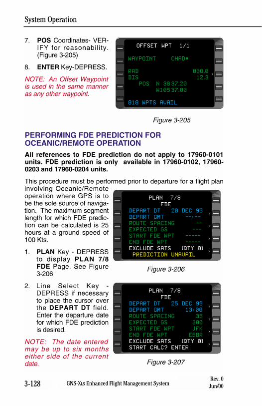
System Operation
3-128 GNS-XLS Enhanced Flight Management SystemRev. 0
Jun/00
7. POS Coordinates- VER-IFY for reasonability.(Figure 3-205)
8. ENTER Key-DEPRESS.
NOTE: An Offset Waypointis used in the same manneras any other waypoint.
PERFORMING FDE PREDICTION FOROCEANIC/REMOTE OPERATIONAll references to FDE prediction do not apply to 17960-0101units. FDE prediction is only available in 17960-0102, 17960-0203 and 17960-0204 units.
This procedure must be performed prior to departure for a flight planinvolving Oceanic/Remoteoperation where GPS is tobe the sole source of naviga-tion. The maximum segmentlength for which FDE predic-tion can be calculated is 25hours at a ground speed of100 Kts.
1. PLAN Key - DEPRESSto display PLAN 7/8FDE Page. See Figure3-206
2. Line Select Key -DEPRESS if necessaryto place the cursor overthe DEPART DT field.Enter the departure datefor which FDE predictionis desired.
NOTE: The date enteredmay be up to six monthseither side of the currentdate.
WAYPOINT CHAD*
RAD 030.0
DIS 12.3
POS N 38 37.20
W105 37.00
818 WPTS AVAIL
OFFSET WPT 1/1
>
Figure 3-205
FDE
DEPART DT 20 DEC 95
DEPART GMT --:--
ROUTE SPACING --
EXPECTED GS ---
START FDE WPT -----
END FDE WPT -----
EXCLUDE SATS (QTY 0)
PREDICTION UNAVAIL
PLAN 7/8
<
<
<
<
Figure 3-206
FDE
DEPART DT 25 DEC 95
DEPART GMT 13:00
ROUTE SPACING 35
EXPECTED GS 300
START FDE WPT JFK
END FDE WPT EBBR
EXCLUDE SATS (QTY 0)
START CALC? ENTER
PLAN 7/8
<
<
<
<
Figure 3-207
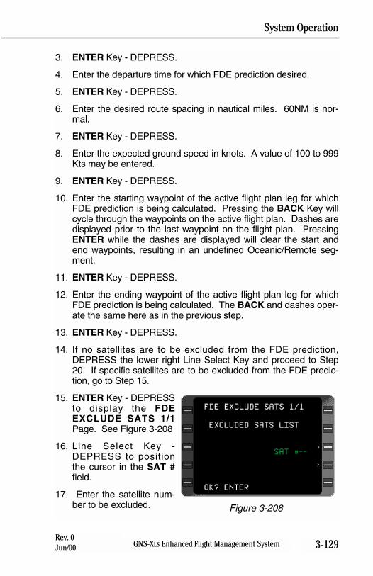
System Operation
3-129GNS-XLS Enhanced Flight Management SystemRev. 0Jun/00
3. ENTER Key - DEPRESS.
4. Enter the departure time for which FDE prediction desired.
5. ENTER Key - DEPRESS.
6. Enter the desired route spacing in nautical miles. 60NM is nor-mal.
7. ENTER Key - DEPRESS.
8. Enter the expected ground speed in knots. A value of 100 to 999Kts may be entered.
9. ENTER Key - DEPRESS.
10. Enter the starting waypoint of the active flight plan leg for whichFDE prediction is being calculated. Pressing the BACK Key willcycle through the waypoints on the active flight plan. Dashes aredisplayed prior to the last waypoint on the flight plan. PressingENTER while the dashes are displayed will clear the start andend waypoints, resulting in an undefined Oceanic/Remote seg-ment.
11. ENTER Key - DEPRESS.
12. Enter the ending waypoint of the active flight plan leg for whichFDE prediction is being calculated. The BACK and dashes oper-ate the same here as in the previous step.
13. ENTER Key - DEPRESS.
14. If no satellites are to be excluded from the FDE prediction,DEPRESS the lower right Line Select Key and proceed to Step20. If specific satellites are to be excluded from the FDE predic-tion, go to Step 15.
15. ENTER Key - DEPRESSto display the FDEEXCLUDE SATS 1/1Page. See Figure 3-208
16. Line Select Key -DEPRESS to positionthe cursor in the SAT #field.
17. Enter the satellite num-ber to be excluded.
EXCLUDED SATS LIST
SAT #--
OK? ENTER
FDE EXCLUDE SATS 1/1
<
<
Figure 3-208
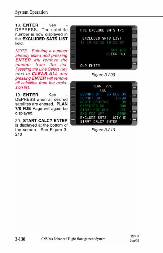
System Operation
3-130 GNS-XLS Enhanced Flight Management SystemRev. 0
Jun/00
18. ENTER Key -DEPRESS. The satellitenumber is now displayed inthe EXCLUDED SATS LISTfield.
NOTE: Entering a numberalready listed and pressingENTER will remove thenumber from the list.Pressing the Line Select Keynext to CLEAR ALL andpressing ENTER will removeall satellites from the exclu-sion list.
19. ENTER Key -DEPRESS when all desiredsatellites are entered. PLAN7/8 FDE Page will again bedisplayed.
20. START CALC? ENTERis displayed at the bottom ofthe screen. See Figure 3-210
FDE
DEPART DT 25 DEC 95
DEPART GMT 13:00
ROUTE SPACING 35
EXPECTED GS 300
START FDE WPT JFK
END FDE WPT EBBR
EXCLUDE SATS (QTY 0)
START CALC? ENTER
PLAN 7/8
<
<
<
<
Figure 3-210
EXCLUDED SATS LIST
12 14 02 16 19 22 07
SAT #02
CLEAR ALL
OK? ENTER
FDE EXCLUDE SATS 1/1
<
<
Figure 3-209
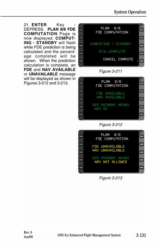
System Operation
3-131GNS-XLS Enhanced Flight Management SystemRev. 0Jun/00
21. ENTER Key -DEPRESS. PLAN 8/8 FDECOMPUTATION Page isnow displayed. COMPUT-ING - STANDBY will flashwhile FDE prediction is beingcalculated and the percent-age completed will beshown. When the predictioncalculation is complete, anFDE and NAV AVAILABLEor UNAVAILABLE messagewill be displayed as shown inFigures 3-212 and 3-213.
FDE COMPUTATION
COMPUTING - STANDBY
51% COMPLETE
CANCEL COMPUTE
PLAN 8/8
<
Figure 3-211
FDE COMPUTATION
FDE AVAILABLE
NAV AVAILABLE
GPS PRIMARY MEANS
NAV OK
PLAN 8/8
Figure 3-212
FDE COMPUTATION
FDE UNAVAILABLE
NAV UNAVAILABLE
GPS PRIMARY MEANS
NAV NOT ALLOWED
PLAN 8/8
Figure 3-213

System Operation
3-132 GNS-XLS Enhanced Flight Management SystemRev. 0
Jun/00
THIS PAGE INTENTIONALLY LEFT BLANK
System Operation
3-133GNS-XLS Enhanced Flight Management SystemRev. 0Jun/00
SEARCH AND RESCUE
Introduction
In addition to the standard GNS-XLS functions, the FMS may be con-figured for special mission capabilities. The following sectiondescribes those capabilities.
Search Patterns
The XLS-MSP generates and steers the aircraft through five searchpattern types; Ladder, Expanding Square, Orbit, Sector Search, andParallel Line. The operator is able to select the pattern and define thespecific parameters appropriate to the mission. Search Patterns canbe activated, cancelled, deleted, or interrupted at any time.
Break and Resume
The search pattern being flown can be interrupted, then resumed atthe operator’s convenience with the aircraft automatically returned tothe point of interruption traveling in the proper direction. This allowsthe crew to maneuver the aircraft freely, while allowing resumption ofthe search pattern with no loss of coverage.
Enhanced Steering
During an active search, the XLS increases the steering gains tothose used during an approach to ensure the aircraft accuratelytracks the search pattern. Also during an active search, the scaling ofthe crosstrack distance indicators is increased to 1 nm full scaledeflection (terminal mode scaling). Configuration for steeper bankangles is provided.
Target Waypoints
The XLS-MSP allows the flight crew to generate target waypoints bydesignating a position via a discrete switch (Mark-On-Target) or viadigital interface such as a weather RADAR. Target waypoints arestored on a flight plan by the XLS for future use. In addition, directnavigation may be selected to one of the latest nine target waypointsfrom the Direct-To Target Waypoints page.
WGS-84 to Tokyo Datum Calculation
The XLS may be configured to provide a special PLAN page to con-vert a position fix between the WGS-84 and the Tokyo coordinatesystems.
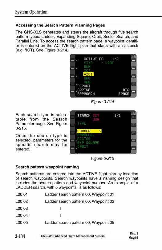
System Operation
3-134 GNS-XLS Enhanced Flight Management SystemRev. 1
May/01
Accessing the Search Pattern Planning Pages
The GNS-XLS generates and steers the aircraft through five searchpattern types: Ladder, Expanding Square, Orbit, Sector Search, andParallel Line. To access the search pattern page, a waypoint identifi-er is entered on the ACTIVE flight plan that starts with an asterisk(e.g. *ICT). See Figure 3-214.
Each search type is selec-table from the SearchParameter page. See Figure3-215.
Once the search type isselected, parameters for thespecific search may beentered.
Search pattern waypoint naming
Search patterns are entered into the ACTIVE flight plan by insertionof search waypoints. Search waypoints have a naming design thatincludes the search pattern and waypoint number. An example of aLADDER search, with 5 waypoints, is as follows:
L00 01 Ladder search pattern 00, Waypoint 01
L00 02 Ladder search pattern 00, Waypoint 02
L00 03 |
L00 04 |
L00 05 Ladder search pattern 00, Waypoint 05
ACTIVE FPL 1/2
KIXD - KSAF
BUM
ICT
*ICT
GAG
ABQ
DEPART
ARRIVE DIS
APPROACH ERASE
<
<
<
<
<
>
Figure 3-214
<
<
<
SEARCH ICT 1/1
USA
TYPE
LADDER ?
PARALLEL
SECTOR
EXP SQUARE
ORBIT
Figure 3-215
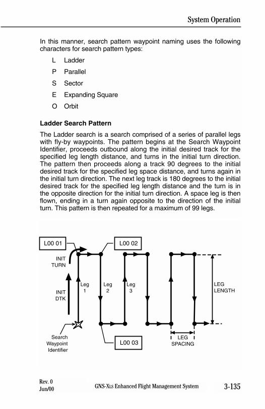
System Operation
3-135GNS-XLS Enhanced Flight Management SystemRev. 0Jun/00
In this manner, search pattern waypoint naming uses the followingcharacters for search pattern types:
L Ladder
P Parallel
S Sector
E Expanding Square
O Orbit
Ladder Search Pattern
The Ladder search is a search comprised of a series of parallel legswith fly-by waypoints. The pattern begins at the Search WaypointIdentifier, proceeds outbound along the initial desired track for thespecified leg length distance, and turns in the initial turn direction.The pattern then proceeds along a track 90 degrees to the initialdesired track for the specified leg space distance, and turns again inthe initial turn direction. The next leg track is 180 degrees to the initialdesired track for the specified leg length distance and the turn is inthe opposite direction for the initial turn direction. A space leg is thenflown, ending in a turn again opposite to the direction of the initialturn. This pattern is then repeated for a maximum of 99 legs.
INITTURN
SearchWaypointIdentifier
Leg1
L00 01 L00 02
L00 03
INITDTK
LEGLENGTH
LEGSPACING
Leg2
Leg3
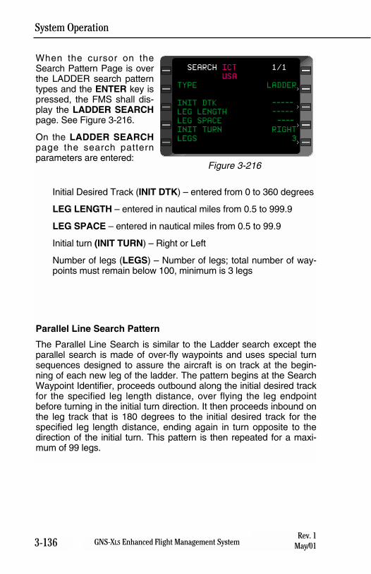
System Operation
3-136 GNS-XLS Enhanced Flight Management SystemRev. 1
May/01
When the cursor on theSearch Pattern Page is overthe LADDER search patterntypes and the ENTER key ispressed, the FMS shall dis-play the LADDER SEARCHpage. See Figure 3-216.
On the LADDER SEARCHpage the search patternparameters are entered:
Initial Desired Track (INIT DTK) – entered from 0 to 360 degrees
LEG LENGTH – entered in nautical miles from 0.5 to 999.9
LEG SPACE – entered in nautical miles from 0.5 to 99.9
Initial turn (INIT TURN) – Right or Left
Number of legs (LEGS) – Number of legs; total number of way-points must remain below 100, minimum is 3 legs
Parallel Line Search Pattern
The Parallel Line Search is similar to the Ladder search except theparallel search is made of over-fly waypoints and uses special turnsequences designed to assure the aircraft is on track at the begin-ning of each new leg of the ladder. The pattern begins at the SearchWaypoint Identifier, proceeds outbound along the initial desired trackfor the specified leg length distance, over flying the leg endpointbefore turning in the initial turn direction. It then proceeds inbound onthe leg track that is 180 degrees to the initial desired track for thespecified leg length distance, ending again in turn opposite to thedirection of the initial turn. This pattern is then repeated for a maxi-mum of 99 legs.
SEARCH ICT 1/1
USA
TYPE LADDER
INIT DTK -----
LEG LENGTH -----
LEG SPACE ----
INIT TURN RIGHT
LEGS 3
<
<
<
<
Figure 3-216
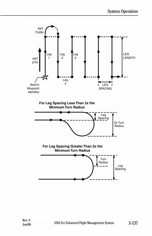
System Operation
3-137GNS-XLS Enhanced Flight Management SystemRev. 0Jun/00
INITTURN
SearchWaypointIdentifier
Leg1INIT
DTK
LEGLENGTH
LEGSPACING
Leg3
Leg5
Leg4
LegSpacing
2x TurnRadius
For Leg Spacing Less Than 2x theMinimum Turn Radius
For Leg Spacing Greater Than 2x theMinimum Turn Radius
TurnRadius
LegSpacing
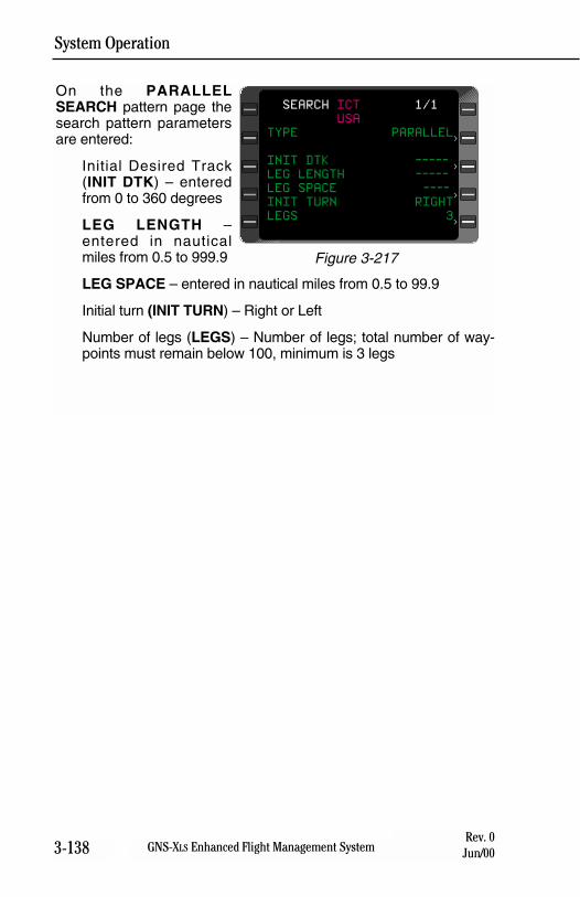
System Operation
3-138 GNS-XLS Enhanced Flight Management SystemRev. 0
Jun/00
On the PARALLELSEARCH pattern page thesearch pattern parametersare entered:
Initial Desired Track(INIT DTK) – enteredfrom 0 to 360 degrees
LEG LENGTH –entered in nauticalmiles from 0.5 to 999.9
LEG SPACE – entered in nautical miles from 0.5 to 99.9
Initial turn (INIT TURN) – Right or Left
Number of legs (LEGS) – Number of legs; total number of way-points must remain below 100, minimum is 3 legs
SEARCH ICT 1/1
USA
TYPE PARALLEL
INIT DTK -----
LEG LENGTH -----
LEG SPACE ----
INIT TURN RIGHT
LEGS 3
<
<
<
<
Figure 3-217
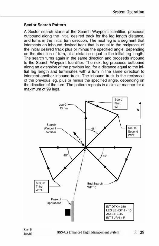
System Operation
3-139GNS-XLS Enhanced Flight Management SystemRev. 0Jun/00
Sector Search Pattern
A Sector search starts at the Search Waypoint Identifier, proceedsoutbound along the initial desired track for the leg length distance,and turns in the initial turn direction. The next leg is a segment thatintercepts an inbound desired track that is equal to the reciprocal ofthe initial desired track plus or minus the specified angle, dependingon the direction of turn, at a distance equal to the initial leg length.The search turns again in the same direction and proceeds inboundto the Search Waypoint Identifier. The next leg proceeds outboundalong an extension of the previous leg, for a distance equal to the ini-tial leg length and terminates with a turn in the same direction tointercept another inbound track. The inbound track is the reciprocalof the previous leg, plus or minus the specified angle, depending onthe direction of the turn. The pattern repeats in a similar manner for amaximum of 99 legs.
SearchWaypointIdentifier
Base ofOperations
End SearchWPT 6
Leg 0115 nm
INT DTK = 360LEG LENGTH = 15ANGLE = 45INT TURN = R
45°
45°
S00 02SecondWPT
S00 01FirstWPT
S00 03ThirdWPT
N
45°
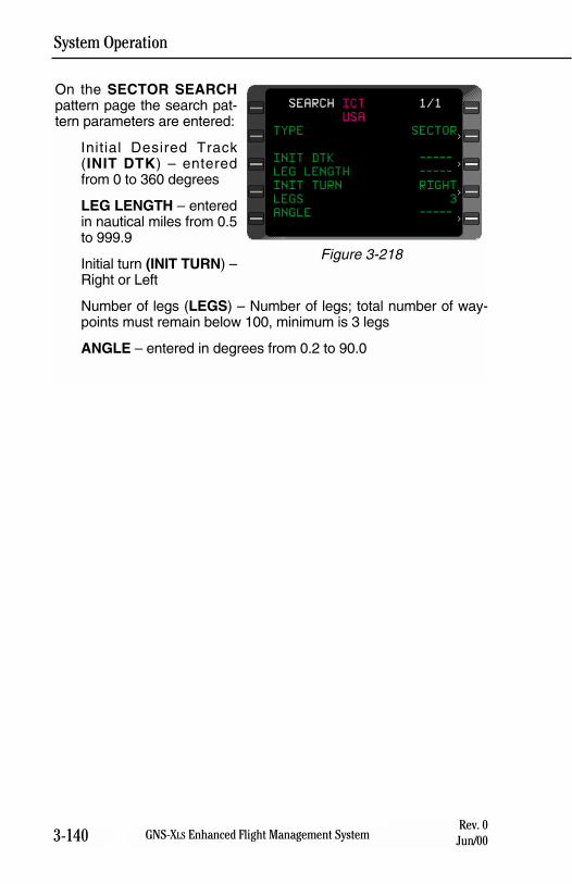
System Operation
3-140 GNS-XLS Enhanced Flight Management SystemRev. 0
Jun/00
On the SECTOR SEARCHpattern page the search pat-tern parameters are entered:
Initial Desired Track(INIT DTK) – enteredfrom 0 to 360 degrees
LEG LENGTH – enteredin nautical miles from 0.5to 999.9
Initial turn (INIT TURN) –Right or Left
Number of legs (LEGS) – Number of legs; total number of way-points must remain below 100, minimum is 3 legs
ANGLE – entered in degrees from 0.2 to 90.0
SEARCH ICT 1/1
USA
TYPE SECTOR
INIT DTK -----
LEG LENGTH -----
INIT TURN RIGHT
LEGS 3
ANGLE -----
<
<
<
<
Figure 3-218
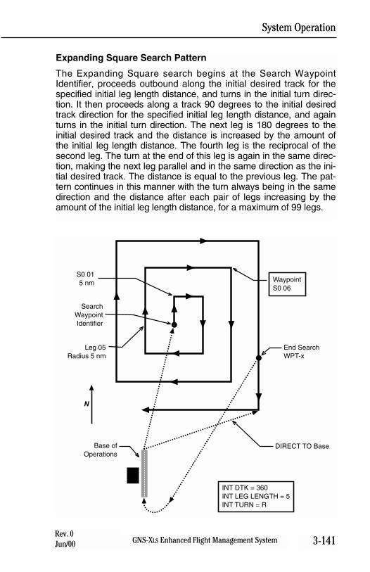
System Operation
3-141GNS-XLS Enhanced Flight Management SystemRev. 0Jun/00
Expanding Square Search Pattern
The Expanding Square search begins at the Search WaypointIdentifier, proceeds outbound along the initial desired track for thespecified initial leg length distance, and turns in the initial turn direc-tion. It then proceeds along a track 90 degrees to the initial desiredtrack direction for the specified initial leg length distance, and againturns in the initial turn direction. The next leg is 180 degrees to theinitial desired track and the distance is increased by the amount ofthe initial leg length distance. The fourth leg is the reciprocal of thesecond leg. The turn at the end of this leg is again in the same direc-tion, making the next leg parallel and in the same direction as the ini-tial desired track. The distance is equal to the previous leg. The pat-tern continues in this manner with the turn always being in the samedirection and the distance after each pair of legs increasing by theamount of the initial leg length distance, for a maximum of 99 legs.
S0 015 nm
SearchWaypointIdentifier
Base ofOperations
End SearchWPT-x
DIRECT TO Base
N
INT DTK = 360INT LEG LENGTH = 5INT TURN = R
Leg 05Radius 5 nm
WaypointS0 06
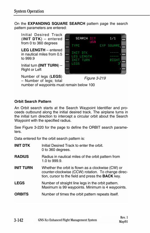
System Operation
3-142 GNS-XLS Enhanced Flight Management SystemRev. 1
May/01
On the EXPANDING SQUARE SEARCH pattern page the searchpattern parameters are entered:
Initial Desired Track(INIT DTK) – enteredfrom 0 to 360 degrees
LEG LENGTH – enteredin nautical miles from 0.5to 999.9
Initial turn (INIT TURN) –Right or Left
Number of legs (LEGS)– Number of legs; totalnumber of waypoints must remain below 100
Orbit Search Pattern
An Orbit search starts at the Search Waypoint Identifier and pro-ceeds outbound along the initial desired track. The airplane turns inthe initial turn direction to intercept a circular orbit about the SearchWaypoint with the specified radius.
See Figure 3-220 for the page to define the ORBIT search parame-ters.
Data entered for the orbit search pattern is:
INIT DTK Initial Desired Track to enter the orbit.0 to 360 degrees.
RADIUS Radius in nautical miles of the orbit pattern from1.0 to 999.9.
INIT TURN Whether the orbit is flown as a clockwise (CW) or counter-clockwise (CCW) rotation. To change direc-tion, cursor to the field and press the BACK key.
LEGS Number of straight line legs in the orbit pattern. Maximum is 99 waypoints. Minimum is 4 waypoints.
ORBITS Number of times the orbit pattern repeats itself.
SEARCH ICT 1/1
USA
TYPE EXP SQUARE
INIT DTK -----
LEG LENGTH -----
INIT TURN RIGHT
LEGS 3<
<
<
<
Figure 3-219
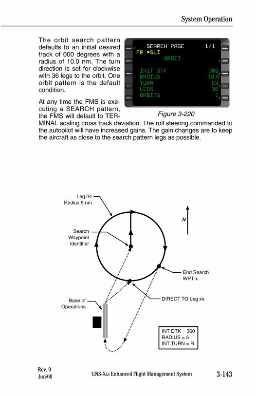
System Operation
3-143GNS-XLS Enhanced Flight Management SystemRev. 0Jun/00
The orbit search patterndefaults to an initial desiredtrack of 000 degrees with aradius of 10.0 nm. The turndirection is set for clockwisewith 36 legs to the orbit. Oneorbit pattern is the defaultcondition.
At any time the FMS is exe-cuting a SEARCH pattern,the FMS will default to TER-MINAL scaling cross track deviation. The roll steering commanded tothe autopilot will have increased gains. The gain changes are to keepthe aircraft as close to the search pattern legs as possible.
SEARCH PAGE 1/1
FR *SLI
ORBIT
INIT DTK 000
RADIUS 10.0
TURN CW
LEGS 36
ORBITS 1
<
<
<
<
<
Figure 3-220
Leg 04Radius 5 nm
SearchWaypointIdentifier
Base ofOperations
End SearchWPT-x
DIRECT TO Leg xx
N
INT DTK = 360RADIUS = 5INT TURN = R
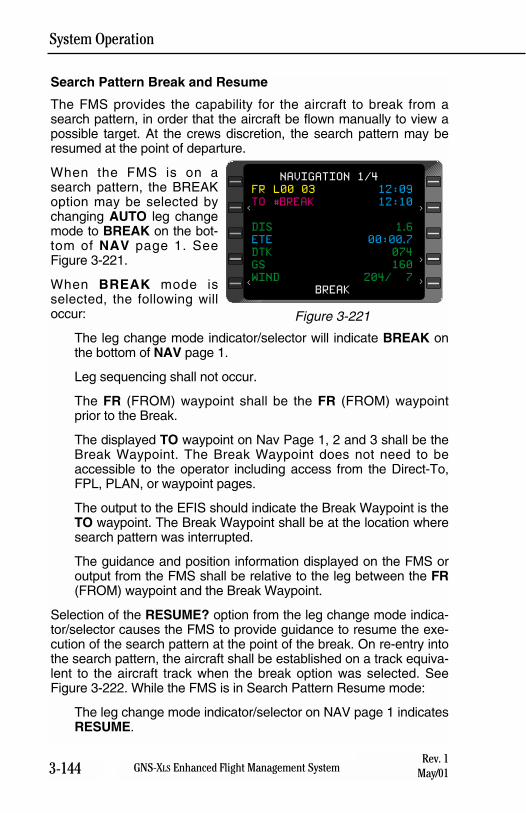
System Operation
3-144 GNS-XLS Enhanced Flight Management SystemRev. 1
May/01
Search Pattern Break and Resume
The FMS provides the capability for the aircraft to break from asearch pattern, in order that the aircraft be flown manually to view apossible target. At the crews discretion, the search pattern may beresumed at the point of departure.
When the FMS is on asearch pattern, the BREAKoption may be selected bychanging AUTO leg changemode to BREAK on the bot-tom of NAV page 1. SeeFigure 3-221.
When BREAK mode isselected, the following willoccur:
The leg change mode indicator/selector will indicate BREAK onthe bottom of NAV page 1.
Leg sequencing shall not occur.
The FR (FROM) waypoint shall be the FR (FROM) waypointprior to the Break.
The displayed TO waypoint on Nav Page 1, 2 and 3 shall be theBreak Waypoint. The Break Waypoint does not need to beaccessible to the operator including access from the Direct-To,FPL, PLAN, or waypoint pages.
The output to the EFIS should indicate the Break Waypoint is theTO waypoint. The Break Waypoint shall be at the location wheresearch pattern was interrupted.
The guidance and position information displayed on the FMS oroutput from the FMS shall be relative to the leg between the FR(FROM) waypoint and the Break Waypoint.
Selection of the RESUME? option from the leg change mode indica-tor/selector causes the FMS to provide guidance to resume the exe-cution of the search pattern at the point of the break. On re-entry intothe search pattern, the aircraft shall be established on a track equiva-lent to the aircraft track when the break option was selected. SeeFigure 3-222. While the FMS is in Search Pattern Resume mode:
The leg change mode indicator/selector on NAV page 1 indicatesRESUME.
NAVIGATION 1/4
FR L00 03 12:09
TO #BREAK 12:10
DIS 1.6
ETE 00:00.7
DTK 074
GS 160
WIND 204/ 7
BREAK
<
< >
>
>
Figure 3-221
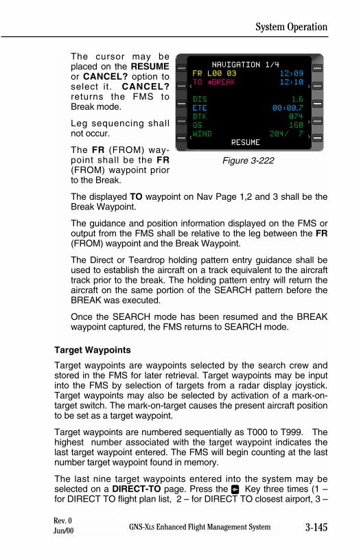
System Operation
3-145GNS-XLS Enhanced Flight Management SystemRev. 0Jun/00
The cursor may beplaced on the RESUMEor CANCEL? option toselect it. CANCEL?returns the FMS toBreak mode.
Leg sequencing shallnot occur.
The FR (FROM) way-point shall be the FR(FROM) waypoint priorto the Break.
The displayed TO waypoint on Nav Page 1,2 and 3 shall be theBreak Waypoint.
The guidance and position information displayed on the FMS oroutput from the FMS shall be relative to the leg between the FR(FROM) waypoint and the Break Waypoint.
The Direct or Teardrop holding pattern entry guidance shall beused to establish the aircraft on a track equivalent to the aircrafttrack prior to the break. The holding pattern entry will return theaircraft on the same portion of the SEARCH pattern before theBREAK was executed.
Once the SEARCH mode has been resumed and the BREAKwaypoint captured, the FMS returns to SEARCH mode.
Target Waypoints
Target waypoints are waypoints selected by the search crew andstored in the FMS for later retrieval. Target waypoints may be inputinto the FMS by selection of targets from a radar display joystick.Target waypoints may also be selected by activation of a mark-on-target switch. The mark-on-target causes the present aircraft positionto be set as a target waypoint.
Target waypoints are numbered sequentially as T000 to T999. Thehighest number associated with the target waypoint indicates thelast target waypoint entered. The FMS will begin counting at the lastnumber target waypoint found in memory.
The last nine target waypoints entered into the system may beselected on a DIRECT-TO page. Press the D Key three times (1 –for DIRECT TO flight plan list, 2 – for DIRECT TO closest airport, 3 –
NAVIGATION 1/4
FR L00 03 12:09
TO #BREAK 12:10
DIS 1.6
ETE 00:00.7
DTK 074
GS 160
WIND 204/ 7
RESUME
<
>
>
>
<
Figure 3-222
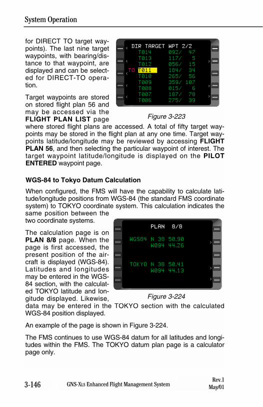
System Operation
3-146 GNS-XLS Enhanced Flight Management SystemRev.1
May/01
for DIRECT TO target way-points). The last nine targetwaypoints, with bearing/dis-tance to that waypoint, aredisplayed and can be select-ed for DIRECT-TO opera-tion.
Target waypoints are storedon stored flight plan 56 andmay be accessed via theFLIGHT PLAN LIST pagewhere stored flight plans are accessed. A total of fifty target way-points may be stored in the flight plan at any one time. Target way-points latitude/longitude may be reviewed by accessing FLIGHTPLAN 56, and then selecting the particular waypoint of interest. Thetarget waypoint latitude/longitude is displayed on the PILOTENTERED waypoint page.
WGS-84 to Tokyo Datum Calculation
When configured, the FMS will have the capability to calculate lati-tude/longitude positions from WGS-84 (the standard FMS coordinatesystem) to TOKYO coordinate system. This calculation indicates thesame position between thetwo coordinate systems.
The calculation page is onPLAN 8/8 page. When thepage is first accessed, thepresent position of the air-craft is displayed (WGS-84).Latitudes and longitudesmay be entered in the WGS-84 section, with the calculat-ed TOKYO latitude and lon-gitude displayed. Likewise,data may be entered in the TOKYO section with the calculatedWGS-84 position displayed.
An example of the page is shown in Figure 3-224.
The FMS continues to use WGS-84 datum for all latitudes and longi-tudes within the FMS. The TOKYO datum plan page is a calculatorpage only.
PLAN 8/8
WGS84 N 38 50.90
W094 44.26
TOKYO N 38 50.41
W094 44.13
>
>
>
Figure 3-224
<
>
>
>
<
DIR TARGET WPT 2/2
T014 092/ 47
T013 117/ 5
T012 056/ 15
TO T011 184/ 34
T010 265/ 56
T009 359/ 107
T008 015/ 6
T007 187/ 78
T006 275/ 39
<
<
<
Figure 3-223
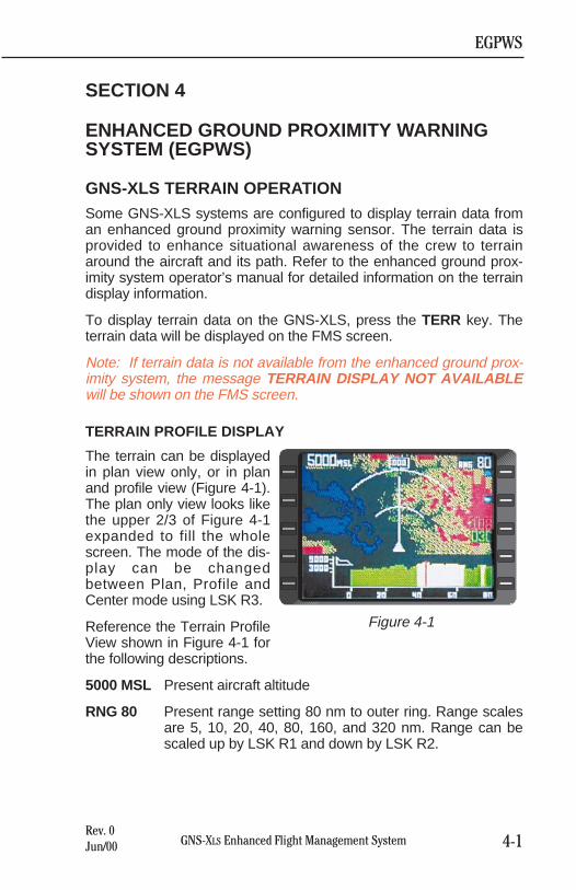
SECTION 4
ENHANCED GROUND PROXIMITY WARNINGSYSTEM (EGPWS)
GNS-XLS TERRAIN OPERATIONSome GNS-XLS systems are configured to display terrain data froman enhanced ground proximity warning sensor. The terrain data isprovided to enhance situational awareness of the crew to terrainaround the aircraft and its path. Refer to the enhanced ground prox-imity system operator’s manual for detailed information on the terraindisplay information.
To display terrain data on the GNS-XLS, press the TERR key. Theterrain data will be displayed on the FMS screen.
Note: If terrain data is not available from the enhanced ground prox-imity system, the message TERRAIN DISPLAY NOT AVAILABLEwill be shown on the FMS screen.
TERRAIN PROFILE DISPLAY
The terrain can be displayedin plan view only, or in planand profile view (Figure 4-1).The plan only view looks likethe upper 2/3 of Figure 4-1expanded to fill the wholescreen. The mode of the dis-play can be changedbetween Plan, Profile andCenter mode using LSK R3.
Reference the Terrain ProfileView shown in Figure 4-1 forthe following descriptions.
5000 MSL Present aircraft altitude
RNG 80 Present range setting 80 nm to outer ring. Range scalesare 5, 10, 20, 40, 80, 160, and 320 nm. Range can bescaled up by LSK R1 and down by LSK R2.
EGPWS
4-1GNS-XLS Enhanced Flight Management SystemRev. 0Jun/00
Figure 4-1
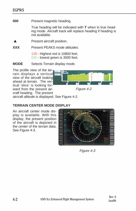
EGPWS
4-2 GNS-XLS Enhanced Flight Management SystemRev. 0Jun/00
000 Present magnetic heading.
True heading will be indicated with T when in true head-ing mode. Aircraft track will replace heading if heading isnot available.
▲ Present aircraft position.
XXX Present PEAKS mode altitudes:
108 - Highest red is 10800 feet.030 - lowest green is 3000 feet.
MODE Selects Terrain display mode.
The profile view of the ter-rain displays a verticalview of the aircraft lookingahead at terrain. The ver-tical ‘slice’ is looking for-ward from the present air-craft heading. The presentaircraft altitude is displayed. See Figure 4-2.
TERRAIN CENTER MODE DISPLAY
An aircraft center mode dis-play is available. With thisdisplay, the present positionof the aircraft is depicted inthe center of the terrain data.See Figure 4-3.
Figure 4-3
Figure 4-2
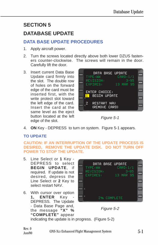
Database Update
5-1GNS-XLS Enhanced Flight Management SystemRev. 0Jun/00
SECTION 5
DATABASE UPDATE
DATA BASE UPDATE PROCEDURES1. Apply aircraft power.
2. Turn the screws located directly above both lower DZUS fasten-ers counter-clockwise. The screws will remain in the door.Carefully lift the door.
3. Insert current Data BaseUpdate card firmly intothe slot. The double rowof holes on the forwardedge of the card must beinserted first, with thewrite protect slot towardthe left edge of the card.Insert the card at thesame level as the ejectbutton located at the leftedge of the slot.
4. ON Key - DEPRESS to turn on system. Figure 5-1 appears.
TO UPDATE
CAUTION: IF AN INTERRUPTION OF THE UPDATE PROCESS ISDESIRED, REMOVE THE UPDATE DISK. DO NOT TURN OFFPOWER TO STOP THE UPDATE.
5. Line Select or 1 Key -DEPRESS to selectBEGIN UPDATE , ifrequired. If update is notdesired, depress theLine Select or 2 Key toselect restart NAV.
6. With cursor over option1, ENTER Key -DEPRESS. The Update- Data Base Page and,the message “X” %“COMPLETE” appearindicating the update is in progress. (Figure 5-2)
TYPE:WW CARD:1/1
REVISION: 3-95
EXPIRES: 13 MAR 95
ENTER CHOICE:
1 BEGIN UPDATE
2 RESTART NAV
(REMOVE CARD)
DATA BASE UPDATE
<
<
Figure 5-1
TYPE:WW CARD:1/1
REVISION: 3-95
EXPIRES: 13 MAR 95
2% COMPLETE
DATA BASE UPDATE
<
<
Figure 5-2
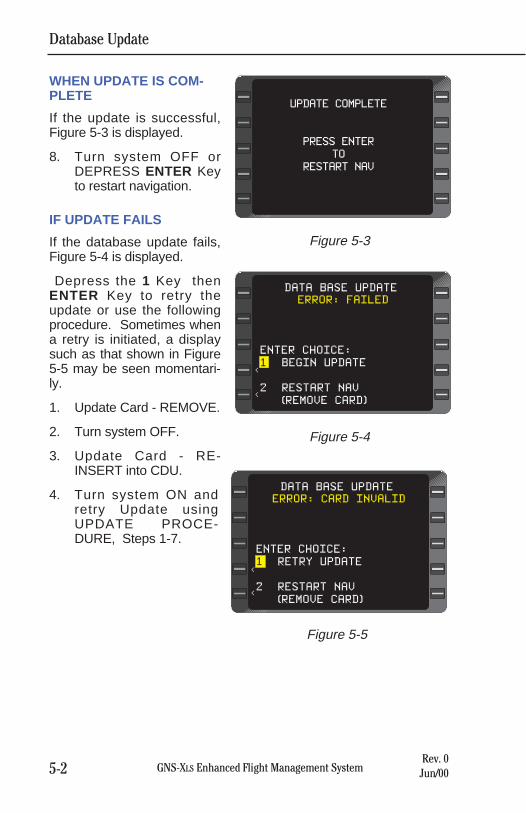
Database Update
5-2 GNS-XLS Enhanced Flight Management SystemRev. 0Jun/00
WHEN UPDATE IS COM-PLETE
If the update is successful,Figure 5-3 is displayed.
8. Turn system OFF orDEPRESS ENTER Keyto restart navigation.
IF UPDATE FAILS
If the database update fails,Figure 5-4 is displayed.
Depress the 1 Key thenENTER Key to retry theupdate or use the followingprocedure. Sometimes whena retry is initiated, a displaysuch as that shown in Figure5-5 may be seen momentari-ly.
1. Update Card - REMOVE.
2. Turn system OFF.
3. Update Card - RE-INSERT into CDU.
4. Turn system ON andretry Update usingUPDATE PROCE-DURE, Steps 1-7.
UPDATE COMPLETE
PRESS ENTER
TO
RESTART NAV
Figure 5-3
ERROR: FAILED
ENTER CHOICE:
1 BEGIN UPDATE
2 RESTART NAV
(REMOVE CARD)
DATA BASE UPDATE
<
<
Figure 5-4
ERROR: CARD INVALID
ENTER CHOICE:
1 RETRY UPDATE
2 RESTART NAV
(REMOVE CARD)
DATA BASE UPDATE
<
<
Figure 5-5
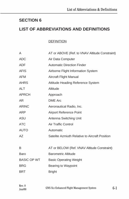
SECTION 6
LIST OF ABBREVIATIONS AND DEFINITIONS
DEFINITION
A AT or ABOVE (Ref. to VNAV Altitude Constraint)
ADC Air Data Computer
ADF Automatic Direction Finder
AFIS Airborne Flight Information System
AFM Aircraft Flight Manual
AHRS Attitude Heading Reference System
ALT Altitude
APRCH Approach
AR DME Arc
ARINC Aeronautical Radio, Inc.
ARP Airport Reference Point
ASU Antenna Switching Unit
ATC Air Traffic Control
AUTO Automatic
AZ Satelite Azmiuth Relative to Aircraft Position
B AT or BELOW (Ref. VNAV Altitude Constraint)
Baro Barometric Altitude
BASIC OP WT Basic Operating Weight
BRG Bearing to Waypoint
BRT Bright
List of Abbreviations & Definitions
6-1GNS-XLS Enhanced Flight Management SystemRev. 0Jun/00
DEFINITION
CDI Course Deviation Indicator
CDU Control Display Unit
CH Channel
CLIMB GRAD Current Aircraft Climb Performance in feet perNautical Mile
CRUISE ALT Cruise Altitude
d Direct To (Laterally)
DB Database
DEF Default
DIF Difference
DIR Direct
DIS Distance
DME Distance Measuring Equipment
DN Down
DTK Desired Track
EFIS Electronic Flight Instrument System
EGPWS Enhanced Ground ProximityWarning System
EL Satelite Elevation Above the Horizon
ELEV Elevation
ENRTE Enroute
EST CROSSING Estimated Crossing Altitude
ETA Estimated Time of Arrival
ETA @ Estimated Time of Arrival at Destination
ETE Estimated Time Enroute
EXP Expires
List of Abbreviations & Definitions
6-2 GNS-XLS Enhanced Flight Management SystemRev. 0Jun/00
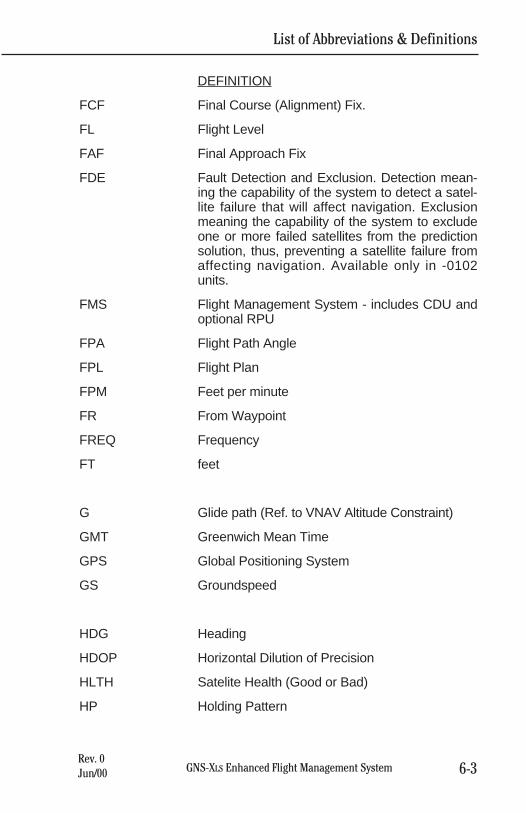
List of Abbreviations & Definitions
6-3GNS-XLS Enhanced Flight Management SystemRev. 0Jun/00
DEFINITION
FCF Final Course (Alignment) Fix.
FL Flight Level
FAF Final Approach Fix
FDE Fault Detection and Exclusion. Detection mean-ing the capability of the system to detect a satel-lite failure that will affect navigation. Exclusionmeaning the capability of the system to excludeone or more failed satellites from the predictionsolution, thus, preventing a satellite failure fromaffecting navigation. Available only in -0102units.
FMS Flight Management System - includes CDU andoptional RPU
FPA Flight Path Angle
FPL Flight Plan
FPM Feet per minute
FR From Waypoint
FREQ Frequency
FT feet
G Glide path (Ref. to VNAV Altitude Constraint)
GMT Greenwich Mean Time
GPS Global Positioning System
GS Groundspeed
HDG Heading
HDOP Horizontal Dilution of Precision
HLTH Satelite Health (Good or Bad)
HP Holding Pattern
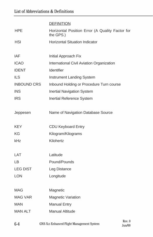
DEFINITION
HPE Horizontal Position Error (A Quality Factor forthe GPS.)
HSI Horizontal Situation Indicator
IAF Initial Approach Fix
ICAO International Civil Aviation Organization
IDENT Identifier
ILS Instrument Landing System
INBOUND CRS Inbound Holding or Procedure Turn course
INS Inertial Navigation System
IRS Inertial Reference System
Jeppesen Name of Navigation Database Source
KEY CDU Keyboard Entry
KG Kilogram/Kilograms
kHz Kilohertz
LAT Latitude
LB Pound/Pounds
LEG DIST Leg Distance
LON Longitude
MAG Magnetic
MAG VAR Magnetic Variation
MAN Manual Entry
MAN ALT Manual Altitude
List of Abbreviations & Definitions
6-4 GNS-XLS Enhanced Flight Management SystemRev. 0Jun/00
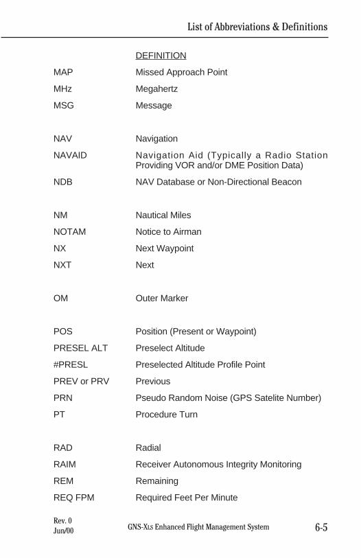
DEFINITION
MAP Missed Approach Point
MHz Megahertz
MSG Message
NAV Navigation
NAVAID Navigation Aid (Typically a Radio StationProviding VOR and/or DME Position Data)
NDB NAV Database or Non-Directional Beacon
NM Nautical Miles
NOTAM Notice to Airman
NX Next Waypoint
NXT Next
OM Outer Marker
POS Position (Present or Waypoint)
PRESEL ALT Preselect Altitude
#PRESL Preselected Altitude Profile Point
PREV or PRV Previous
PRN Pseudo Random Noise (GPS Satelite Number)
PT Procedure Turn
RAD Radial
RAIM Receiver Autonomous Integrity Monitoring
REM Remaining
REQ FPM Required Feet Per Minute
List of Abbreviations & Definitions
6-5GNS-XLS Enhanced Flight Management SystemRev. 0Jun/00
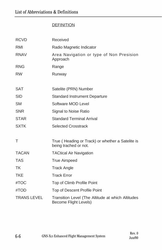
List of Abbreviations & Definitions
6-6 GNS-XLS Enhanced Flight Management SystemRev. 0Jun/00
DEFINITION
RCVD Received
RMI Radio Magnetic Indicator
RNAV Area Navigation or type of Non PresisionApproach
RNG Range
RW Runway
SAT Satelite (PRN) Number
SID Standard Instrument Departure
SM Software MOD Level
SNR Signal to Noise Ratio
STAR Standard Terminal Arrival
SXTK Selected Crosstrack
T True ( Heading or Track) or whether a Satelite isbeing trached or not.
TACAN TACtical Air Navigation
TAS True Airspeed
TK Track Angle
TKE Track Error
#TOC Top of Climb Profile Point
#TOD Top of Descent Profile Point
TRANS LEVEL Transition Level (The Altitude at which AltitudesBecome Flight Levels)
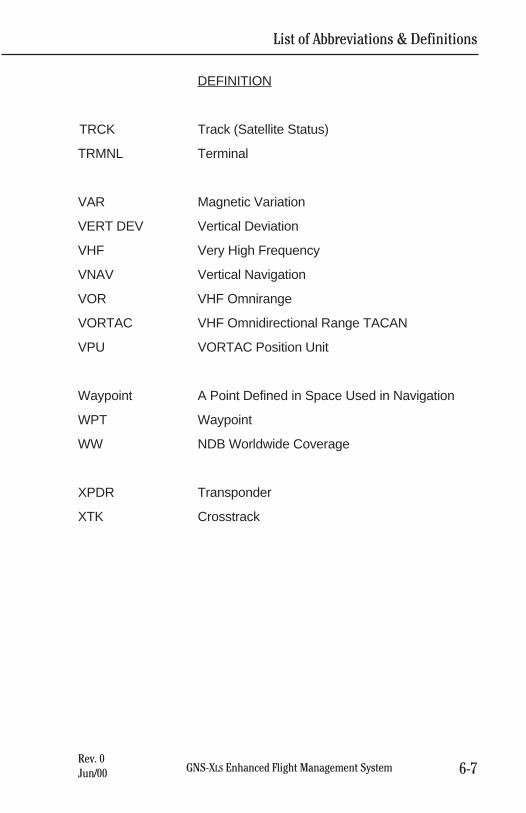
DEFINITION
TRCK Track (Satellite Status)
TRMNL Terminal
VAR Magnetic Variation
VERT DEV Vertical Deviation
VHF Very High Frequency
VNAV Vertical Navigation
VOR VHF Omnirange
VORTAC VHF Omnidirectional Range TACAN
VPU VORTAC Position Unit
Waypoint A Point Defined in Space Used in Navigation
WPT Waypoint
WW NDB Worldwide Coverage
XPDR Transponder
XTK Crosstrack
List of Abbreviations & Definitions
6-7GNS-XLS Enhanced Flight Management SystemRev. 0Jun/00

List of Abbreviations & Definitions
6-8 GNS-XLS Enhanced Flight Management SystemRev. 0Jun/00
THIS PAGE INTENTIONALLY LEFT BLANK
GNS-XLS Enhanced Flight Management System AFIS OperationRev. 0Jun/00
SECTION 7
AFISAIRBORNE FLIGHT INFORMATION SYSTEM
AND
SATELLITE DATA COMMUNICATIONS SYSTEM
This section applies only to aircraft equipped with an AFIS system.
The purpose of this section is to acquaint users of AFIS Flight Planand Weather Advisory Services with the equipment, its capabilities,and its operation. AFIS services are ADVISORY only, as they con-tain elements provided by the National Weather Service and informa-tion supplied by the pilot. Therefore, it is the responsibility of the pilotin command to exercise reasonable and prudent judgment in the useof these ADVISORY services.

GNS-XLS Enhanced Flight Management System AFIS OperationRev. 0Jun/00
THIS PAGE INTENTIONALLY LEFT BLANK
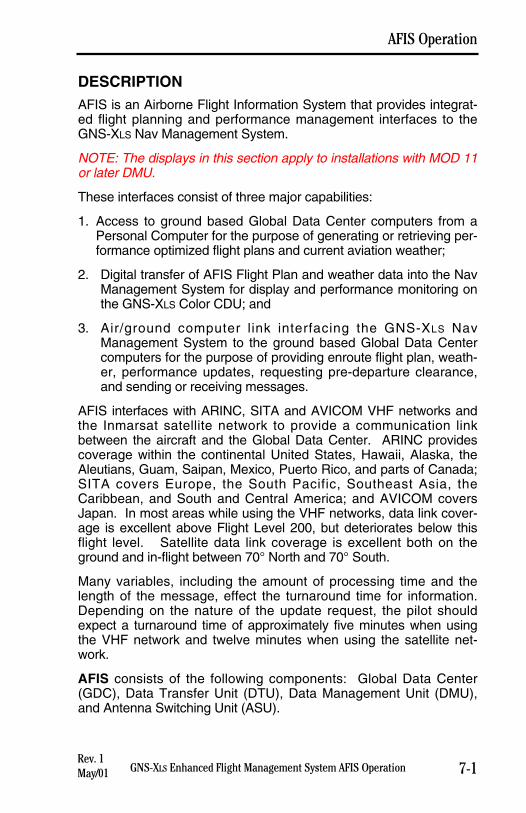
DESCRIPTIONAFIS is an Airborne Flight Information System that provides integrat-ed flight planning and performance management interfaces to theGNS-XLS Nav Management System.
NOTE: The displays in this section apply to installations with MOD 11or later DMU.
These interfaces consist of three major capabilities:
1. Access to ground based Global Data Center computers from aPersonal Computer for the purpose of generating or retrieving per-formance optimized flight plans and current aviation weather;
2. Digital transfer of AFIS Flight Plan and weather data into the NavManagement System for display and performance monitoring onthe GNS-XLS Color CDU; and
3. Air/ground computer link interfacing the GNS-XLS NavManagement System to the ground based Global Data Centercomputers for the purpose of providing enroute flight plan, weath-er, performance updates, requesting pre-departure clearance,and sending or receiving messages.
AFIS interfaces with ARINC, SITA and AVICOM VHF networks andthe Inmarsat satellite network to provide a communication linkbetween the aircraft and the Global Data Center. ARINC providescoverage within the continental United States, Hawaii, Alaska, theAleutians, Guam, Saipan, Mexico, Puerto Rico, and parts of Canada;SITA covers Europe, the South Pacific, Southeast Asia, theCaribbean, and South and Central America; and AVICOM coversJapan. In most areas while using the VHF networks, data link cover-age is excellent above Flight Level 200, but deteriorates below thisflight level. Satellite data link coverage is excellent both on theground and in-flight between 70° North and 70° South.
Many variables, including the amount of processing time and thelength of the message, effect the turnaround time for information.Depending on the nature of the update request, the pilot shouldexpect a turnaround time of approximately five minutes when usingthe VHF network and twelve minutes when using the satellite net-work.
AFIS consists of the following components: Global Data Center(GDC), Data Transfer Unit (DTU), Data Management Unit (DMU),and Antenna Switching Unit (ASU).
7-1GNS-XLS Enhanced Flight Management System AFIS OperationRev. 1May/01
AFIS Operation
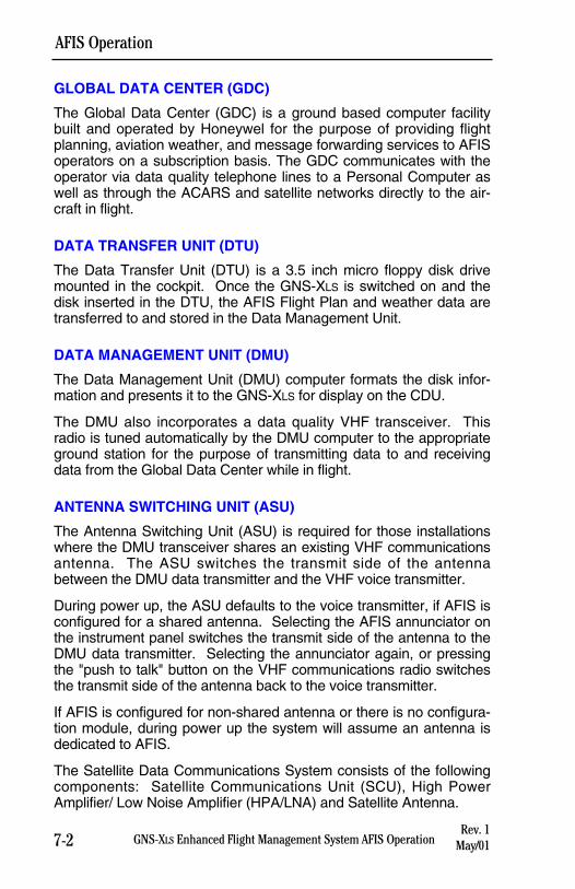
7-2 GNS-XLS Enhanced Flight Management System AFIS OperationRev. 1
May/01
AFIS Operation
GLOBAL DATA CENTER (GDC)
The Global Data Center (GDC) is a ground based computer facilitybuilt and operated by Honeywel for the purpose of providing flightplanning, aviation weather, and message forwarding services to AFISoperators on a subscription basis. The GDC communicates with theoperator via data quality telephone lines to a Personal Computer aswell as through the ACARS and satellite networks directly to the air-craft in flight.
DATA TRANSFER UNIT (DTU)
The Data Transfer Unit (DTU) is a 3.5 inch micro floppy disk drivemounted in the cockpit. Once the GNS-XLS is switched on and thedisk inserted in the DTU, the AFIS Flight Plan and weather data aretransferred to and stored in the Data Management Unit.
DATA MANAGEMENT UNIT (DMU)
The Data Management Unit (DMU) computer formats the disk infor-mation and presents it to the GNS-XLS for display on the CDU.
The DMU also incorporates a data quality VHF transceiver. Thisradio is tuned automatically by the DMU computer to the appropriateground station for the purpose of transmitting data to and receivingdata from the Global Data Center while in flight.
ANTENNA SWITCHING UNIT (ASU)
The Antenna Switching Unit (ASU) is required for those installationswhere the DMU transceiver shares an existing VHF communicationsantenna. The ASU switches the transmit side of the antennabetween the DMU data transmitter and the VHF voice transmitter.
During power up, the ASU defaults to the voice transmitter, if AFIS isconfigured for a shared antenna. Selecting the AFIS annunciator onthe instrument panel switches the transmit side of the antenna to theDMU data transmitter. Selecting the annunciator again, or pressingthe "push to talk" button on the VHF communications radio switchesthe transmit side of the antenna back to the voice transmitter.
If AFIS is configured for non-shared antenna or there is no configura-tion module, during power up the system will assume an antenna isdedicated to AFIS.
The Satellite Data Communications System consists of the followingcomponents: Satellite Communications Unit (SCU), High PowerAmplifier/ Low Noise Amplifier (HPA/LNA) and Satellite Antenna.
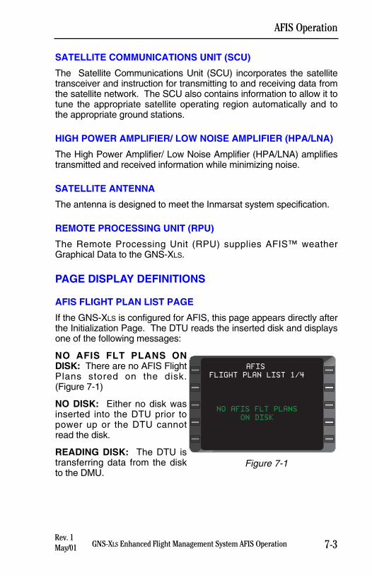
7-3GNS-XLS Enhanced Flight Management System AFIS OperationRev. 1May/01
AFIS Operation
SATELLITE COMMUNICATIONS UNIT (SCU)
The Satellite Communications Unit (SCU) incorporates the satellitetransceiver and instruction for transmitting to and receiving data fromthe satellite network. The SCU also contains information to allow it totune the appropriate satellite operating region automatically and tothe appropriate ground stations.
HIGH POWER AMPLIFIER/ LOW NOISE AMPLIFIER (HPA/LNA)
The High Power Amplifier/ Low Noise Amplifier (HPA/LNA) amplifiestransmitted and received information while minimizing noise.
SATELLITE ANTENNA
The antenna is designed to meet the Inmarsat system specification.
REMOTE PROCESSING UNIT (RPU)
The Remote Processing Unit (RPU) supplies AFIS™ weatherGraphical Data to the GNS-XLS.
PAGE DISPLAY DEFINITIONS
AFIS FLIGHT PLAN LIST PAGE
If the GNS-XLS is configured for AFIS, this page appears directly afterthe Initialization Page. The DTU reads the inserted disk and displaysone of the following messages:
NO AFIS FLT PLANS ONDISK: There are no AFIS FlightPlans stored on the disk.(Figure 7-1)
NO DISK: Either no disk wasinserted into the DTU prior topower up or the DTU cannotread the disk.
READING DISK: The DTU istransferring data from the diskto the DMU.
FLIGHT PLAN LIST 1/4
NO AFIS FLT PLANS
ON DISK
AFIS
Figure 7-1
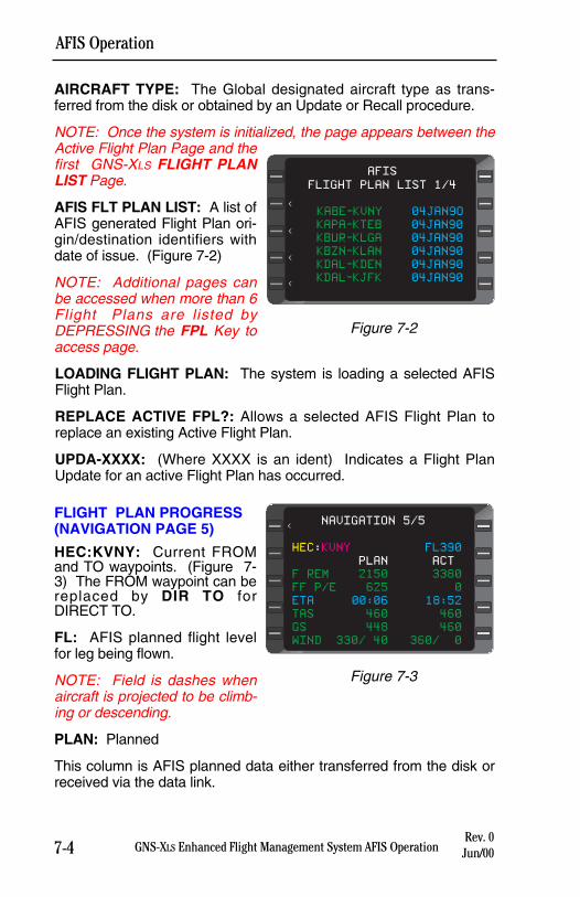
7-4 GNS-XLS Enhanced Flight Management System AFIS OperationRev. 0
Jun/00
AFIS Operation
AIRCRAFT TYPE: The Global designated aircraft type as trans-ferred from the disk or obtained by an Update or Recall procedure.
NOTE: Once the system is initialized, the page appears between theActive Flight Plan Page and thefirst GNS-XLS FLIGHT PLANLIST Page.
AFIS FLT PLAN LIST: A list ofAFIS generated Flight Plan ori-gin/destination identifiers withdate of issue. (Figure 7-2)
NOTE: Additional pages canbe accessed when more than 6Flight Plans are listed byDEPRESSING the FPL Key toaccess page.
LOADING FLIGHT PLAN: The system is loading a selected AFISFlight Plan.
REPLACE ACTIVE FPL?: Allows a selected AFIS Flight Plan toreplace an existing Active Flight Plan.
UPDA-XXXX: (Where XXXX is an ident) Indicates a Flight PlanUpdate for an active Flight Plan has occurred.
FLIGHT PLAN PROGRESS(NAVIGATION PAGE 5)
HEC:KVNY: Current FROMand TO waypoints. (Figure 7-3) The FROM waypoint can bereplaced by DIR TO forDIRECT TO.
FL: AFIS planned flight levelfor leg being flown.
NOTE: Field is dashes whenaircraft is projected to be climb-ing or descending.
PLAN: Planned
This column is AFIS planned data either transferred from the disk orreceived via the data link.
FLIGHT PLAN LIST 1/4
KABE-KVNY 04JAN9O
KAPA-KTEB 04JAN90
KBUR-KLGA 04JAN90
KBZN-KLAN 04JAN90
KDAL-KDEN 04JAN90
KDAL-KJFK 04JAN90
AFIS
<
<
<
<
Figure 7-2
HEC:KVNY FL390
PLAN ACT
F REM 2150 3380
FF P/E 625 0
ETA 00:06 18:52
TAS 460 460
GS 448 460
WIND 330/ 40 360/ 0
NAVIGATION 5/5<
Figure 7-3
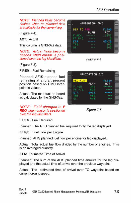
7-5GNS-XLS Enhanced Flight Management System AFIS OperationRev. 0Jun/00
AFIS Operation
NOTE: Planned fields becomedashes when no planned datais available for the current leg.
(Figure 7-4).
ACT: Actual
This column is GNS-XLS data.
NOTE: Actual fields becomedashes when cursor is posi-tioned over the leg identifiers.
(Figure 7-5).
F REM: Fuel Remaining
Planned: AFIS planned fuelremaining at aircraft presentposition based on DMU inter-polated values.
Actual: The total fuel on boardas calculated by the GNS-XLS.
NOTE: Field changes to FREQ when cursor is positionedover the leg identifiers
F REQ: Fuel Required
Planned: The AFIS planned fuel required to fly the leg displayed.
FF P/E: Fuel Flow per Engine
Planned: AFIS planned fuel flow per engine for leg displayed.
Actual: Total actual fuel flow divided by the number of engines. Thisis an averaged quantity.
ETA: Estimated Time of Arrival
Planned: The sum of the AFIS planned time enroute for the leg dis-played and the actual time of arrival over the previous waypoint.
Actual: The estimated time of arrival over TO waypoint based oncurrent groundspeed.
DIR TO:PSB FL390
PLAN ACT
F REM ------ 11952
FF P/E ---- 0
ETA ----- 05:26
TAS --- 300
GS --- 300
NAVIGATION 5/5<
Figure 7-4
NAVIGATION 5/5<
HEC:KVNY FL390
PLAN ACT
F REM 375 ------
FF P/E 625 ----
ETA 0+16 -----
TAS 460 ---
GS 448 ---
Figure 7-5
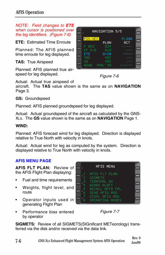
NOTE: Field changes to ETEwhen cursor is positioned overthe leg identifiers. (Figure 7-6)
ETE: Estimated Time Enroute
Planned: The AFIS plannedtime enroute for leg displayed.
TAS: True Airspeed
Planned: AFIS planned true air-speed for leg displayed.
Actual: Actual true airspeed ofaircraft. The TAS value shown is the same as on NAVIGATIONPage 3.
GS: Groundspeed
Planned: AFIS planned groundspeed for leg displayed.
Actual: Actual groundspeed of the aircraft as calculated by the GNS-XLS. The GS value shown is the same as on NAVIGATION Page 1.
WIND:
Planned: AFIS forecast wind for leg displayed. Direction is displayedrelative to True North with velocity in knots.
Actual: Actual wind for leg as computed by the system. Direction isdisplayed relative to True North with velocity in knots.
AFIS MENU PAGE
AFIS FLT PLAN: Review ofthe AFIS Flight Plan displaying:
• Fuel and time requirements
• Weights, flight level, androute
• Operator inputs used ingenerating Flight Plan
• Performance bias enteredby operator
SIGMETS: Review of all SIGMETS(SIGnificant METeorology) trans-ferred via the disk and/or received via the data link.
7-6 GNS-XLS Enhanced Flight Management System AFIS OperationRev. 0
Jun/00
AFIS Operation
NAVIGATION 5/5<
PGS:HEC FL390
PLAN ACT
F REQ 624 ------
FF P/E 619 ----
ETE 0+20 -----
TAS 457 ---
GS 452 ---
WIND 340/ 39 ---/---
Figure 7-6
AFIS MENU
1 AFIS FLT PLAN
2 SIGMETS
3 TERMINAL WX
4 WINDS ALOFT
5 RECALL AFIS FPL
6 SEND AFIS MSG
7 DISPL AFIS MSG
8 OPERATING MODES
<
<
<
<
<
Figure 7-7
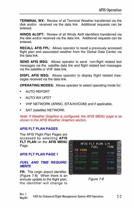
TERMINAL WX: Review of all Terminal Weather transferred via thedisk and/or received via the data link. Additional requests can beentered.
WINDS ALOFT: Review of all Winds Aloft identifiers transferred viathe disk and/or received via the data link. Additional requests can beentered.
RECALL AFIS FPL: Allows operator to recall a previously accessedflight plan and associated weather from the Global Data Center viathe data link.
SEND AFIS MSG: Allows operator to send non-flight related textmessages via the satellite data link and flight related text messagesvia the satellite or VHF data link.
DISPL AFIS MSG: Allows operator to display flight related mes-sages received via the data link.
OPERATING MODES: Allows operator to select operating mode for:
• AUTO REPORT
• AUTO WX UPDT
• VHF NETWORK (ARINC, SITA/AVICOM) and if applicable,
• SAT (satellite) NETWORK.
Note: If Weather Graphics is configured, the AFIS MENU page is asshown in the AFIS Weather Graphics section.
AFIS FLT PLAN PAGES
The AFIS Flight Plan Pages areaccessed by selecting AFISFLT PLAN on the AFIS MENUPage.
AFIS FLT PLAN PAGE 1
FUEL AND TIME REQUIRE-MENTS
FR: The origin airport identifier.(Figure 7-8) When there is anenroute update to the flight plan,the identifier will change to
7-7GNS-XLS Enhanced Flight Management System AFIS OperationRev. 1May/01
AFIS Operation
FUEL TIME
FR KSNA
TO KJFK 8806 4+30
HOLDING ----- -----
TO ---- ----- -----
RESERVE 2000 1+03
TOTALS 10806 5+33
AFIS FLT PLAN 1/4
Figure 7-8
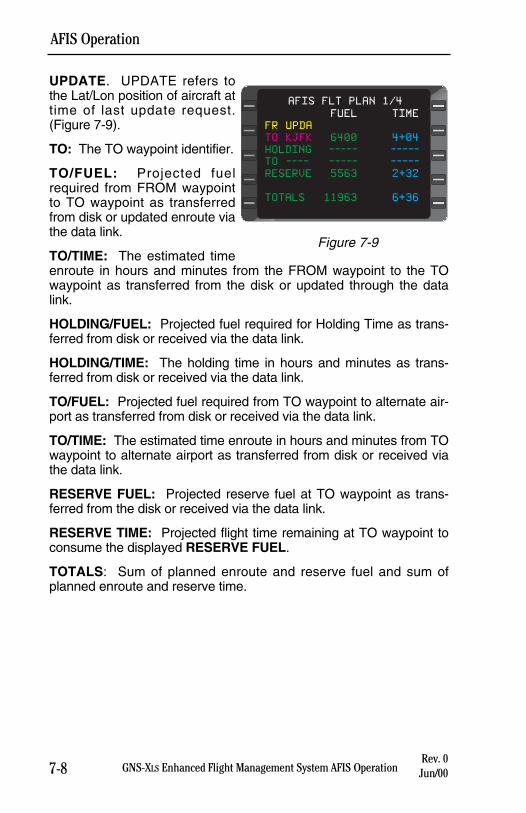
7-8 GNS-XLS Enhanced Flight Management System AFIS OperationRev. 0
Jun/00
AFIS Operation
UPDATE. UPDATE refers tothe Lat/Lon position of aircraft attime of last update request.(Figure 7-9).
TO: The TO waypoint identifier.
TO/FUEL: Projected fuelrequired from FROM waypointto TO waypoint as transferredfrom disk or updated enroute viathe data link.
TO/TIME: The estimated timeenroute in hours and minutes from the FROM waypoint to the TOwaypoint as transferred from the disk or updated through the datalink.
HOLDING/FUEL: Projected fuel required for Holding Time as trans-ferred from disk or received via the data link.
HOLDING/TIME: The holding time in hours and minutes as trans-ferred from disk or received via the data link.
TO/FUEL: Projected fuel required from TO waypoint to alternate air-port as transferred from disk or received via the data link.
TO/TIME: The estimated time enroute in hours and minutes from TOwaypoint to alternate airport as transferred from disk or received viathe data link.
RESERVE FUEL: Projected reserve fuel at TO waypoint as trans-ferred from the disk or received via the data link.
RESERVE TIME: Projected flight time remaining at TO waypoint toconsume the displayed RESERVE FUEL.
TOTALS: Sum of planned enroute and reserve fuel and sum ofplanned enroute and reserve time.
FUEL TIME
FR UPDA
TO KJFK 6400 4+04
HOLDING ----- -----
TO ---- ----- -----
RESERVE 5563 2+32
TOTALS 11963 6+36
AFIS FLT PLAN 1/4
Figure 7-9
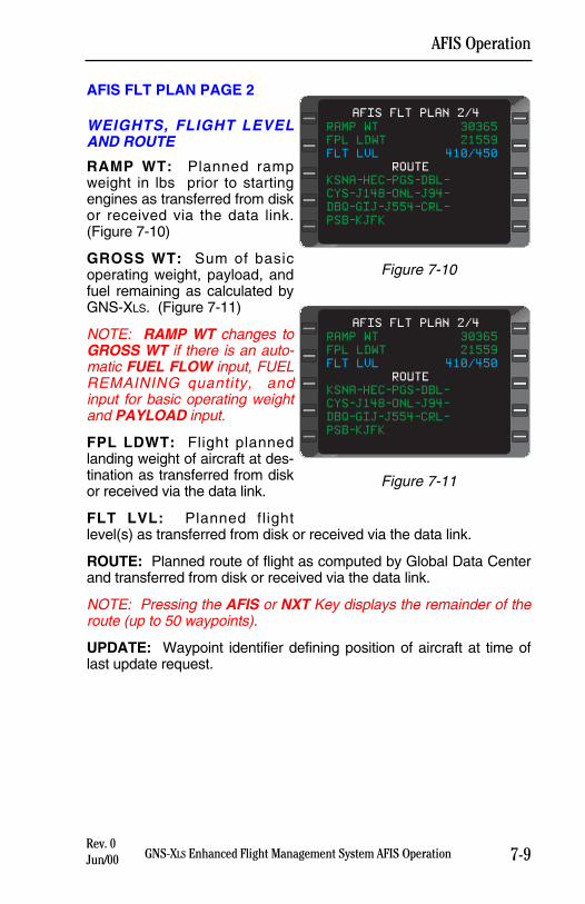
AFIS FLT PLAN PAGE 2
WEIGHTS, FLIGHT LEVELAND ROUTE
RAMP WT: Planned rampweight in lbs prior to startingengines as transferred from diskor received via the data link.(Figure 7-10)
GROSS WT: Sum of basicoperating weight, payload, andfuel remaining as calculated byGNS-XLS. (Figure 7-11)
NOTE: RAMP WT changes toGROSS WT if there is an auto-matic FUEL FLOW input, FUELREMAINING quantity, andinput for basic operating weightand PAYLOAD input.
FPL LDWT: Flight plannedlanding weight of aircraft at des-tination as transferred from diskor received via the data link.
FLT LVL: Planned flightlevel(s) as transferred from disk or received via the data link.
ROUTE: Planned route of flight as computed by Global Data Centerand transferred from disk or received via the data link.
NOTE: Pressing the AFIS or NXT Key displays the remainder of theroute (up to 50 waypoints).
UPDATE: Waypoint identifier defining position of aircraft at time oflast update request.
7-9GNS-XLS Enhanced Flight Management System AFIS OperationRev. 0Jun/00
AFIS Operation
RAMP WT 30365
FPL LDWT 21559
FLT LVL 410/450
ROUTE
KSNA-HEC-PGS-DBL-
CYS-J148-ONL-J94-
DBQ-GIJ-J554-CRL-
PSB-KJFK
AFIS FLT PLAN 2/4
Figure 7-10
RAMP WT 30365
FPL LDWT 21559
FLT LVL 410/450
ROUTE
KSNA-HEC-PGS-DBL-
CYS-J148-ONL-J94-
DBQ-GIJ-J554-CRL-
PSB-KJFK
AFIS FLT PLAN 2/4
Figure 7-11
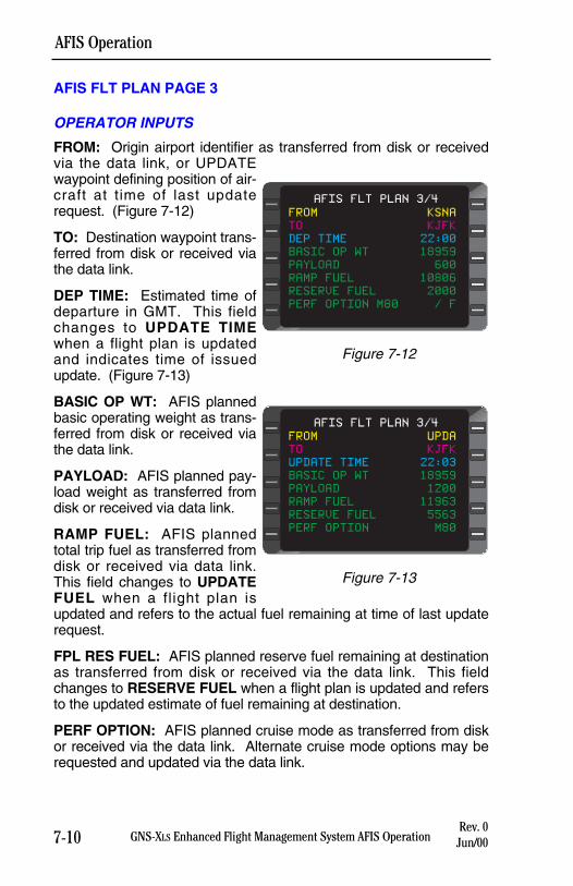
7-10Rev. 0
Jun/00
AFIS Operation
GNS-XLS Enhanced Flight Management System AFIS Operation
AFIS FLT PLAN PAGE 3
OPERATOR INPUTS
FROM: Origin airport identifier as transferred from disk or receivedvia the data link, or UPDATEwaypoint defining position of air-craft at time of last updaterequest. (Figure 7-12)
TO: Destination waypoint trans-ferred from disk or received viathe data link.
DEP TIME: Estimated time ofdeparture in GMT. This fieldchanges to UPDATE TIMEwhen a flight plan is updatedand indicates time of issuedupdate. (Figure 7-13)
BASIC OP WT: AFIS plannedbasic operating weight as trans-ferred from disk or received viathe data link.
PAYLOAD: AFIS planned pay-load weight as transferred fromdisk or received via data link.
RAMP FUEL: AFIS plannedtotal trip fuel as transferred fromdisk or received via data link.This field changes to UPDATEFUEL when a flight plan isupdated and refers to the actual fuel remaining at time of last updaterequest.
FPL RES FUEL: AFIS planned reserve fuel remaining at destinationas transferred from disk or received via the data link. This fieldchanges to RESERVE FUEL when a flight plan is updated and refersto the updated estimate of fuel remaining at destination.
PERF OPTION: AFIS planned cruise mode as transferred from diskor received via the data link. Alternate cruise mode options may berequested and updated via the data link.
FROM KSNA
TO KJFK
DEP TIME 22:00
BASIC OP WT 18959
PAYLOAD 600
RAMP FUEL 10806
RESERVE FUEL 2000
PERF OPTION M80 / F
AFIS FLT PLAN 3/4
Figure 7-12
FROM UPDA
TO KJFK
UPDATE TIME 22:03
BASIC OP WT 18959
PAYLOAD 1200
RAMP FUEL 11963
RESERVE FUEL 5563
PERF OPTION M80
AFIS FLT PLAN 3/4
Figure 7-13
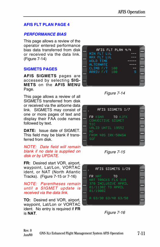
7-11GNS-XLS Enhanced Flight Management System AFIS OperationRev. 0Jun/00
AFIS Operation
AFIS FLT PLAN PAGE 4
PERFORMANCE BIAS
This page allows a review of theoperator entered performancebias data transferred from diskor received via the data link.(Figure 7-14)
SIGMETS PAGES
AFIS SIGMETS pages areaccessed by selecting SIG-METS on the AFIS MENUPage.
This page allows a review of allSIGMETS transferred from diskor received via the airborne datalink. SIGMETS may consist ofone or more pages of text anddisplay their FAA code namesfollowed by text.
DATE: Issue date of SIGMET.This field may be blank if trans-ferred from disk.
NOTE: Date field will remainblank if no date is supplied ondisk or by UPDATE.
FR: Desired start VOR, airport,waypoint, Lat/Lon, VORTACident, or NAT (North AtlanticTracks). (Figure 7-15 or 7-16)
NOTE: Parentheses remainuntil a SIGMET update isreceived via the data link.
TO: Desired end VOR, airport,waypoint, Lat/Lon or VORTACident. No entry is required if FRis NAT.
MIN FLT LVL ---
MAX FLT LVL ---
HOLD TIME -----
ALTERNATE ----
CLIMB F/T 100 --
ARRIV F/T 100 5
AFIS FLT PLAN 4/4
Figure 7-14
FR KSNA TO KJFK
CONVECTIVE SIGMET
51C
VALID UNTIL 1955Z
MO
FROM 40S IRK-50WSW
SGF
AFIS SIGMETS 1/7<
Figure 7-15
FR NAT TO
NAT TRACKS FLS 310
370 INCLUSIVE APRIL
01/1130Z TO APRIL
01/1900Z
A 63/30 63/40 63/50
AFIS SIGMETS 1/29<
Figure 7-16
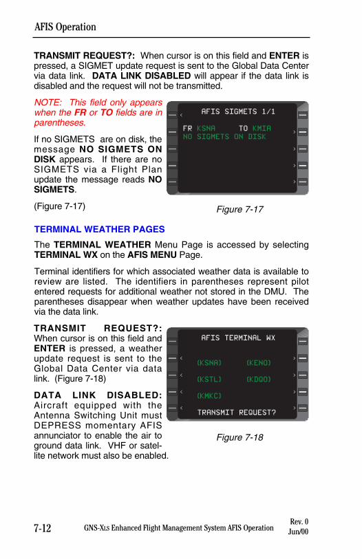
7-12 GNS-XLS Enhanced Flight Management System AFIS OperationRev. 0
Jun/00
AFIS Operation
TRANSMIT REQUEST?: When cursor is on this field and ENTER ispressed, a SIGMET update request is sent to the Global Data Centervia data link. DATA LINK DISABLED will appear if the data link isdisabled and the request will not be transmitted.
NOTE: This field only appearswhen the FR or TO fields are inparentheses.
If no SIGMETS are on disk, themessage NO SIGMETS ONDISK appears. If there are noSIGMETS via a Flight Planupdate the message reads NOSIGMETS.
(Figure 7-17)
TERMINAL WEATHER PAGES
The TERMINAL WEATHER Menu Page is accessed by selectingTERMINAL WX on the AFIS MENU Page.
Terminal identifiers for which associated weather data is available toreview are listed. The identifiers in parentheses represent pilotentered requests for additional weather not stored in the DMU. Theparentheses disappear when weather updates have been receivedvia the data link.
TRANSMIT REQUEST?:When cursor is on this field andENTER is pressed, a weatherupdate request is sent to theGlobal Data Center via datalink. (Figure 7-18)
DATA LINK DISABLED:Aircraft equipped with theAntenna Switching Unit mustDEPRESS momentary AFISannunciator to enable the air toground data link. VHF or satel-lite network must also be enabled.
(KSNA) (KENO)
(KSTL) (KDQO)
(KMKC)
TRANSMIT REQUEST?
AFIS TERMINAL WX
<
<
<
<
>
>
>
>
Figure 7-18
FR KSNA TO KMIA
NO SIGMETS ON DISK
AFIS SIGMETS 1/1
<
<
<
<
>
>
>
>
<
Figure 7-17
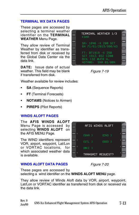
TERMINAL WX DATA PAGES
These pages are accessed byselecting a terminal weatheridentifier on the TERMINALWEATHER Menu Page.
They allow review of TerminalWeather by identifier as trans-ferred from disk or received bythe Global Data Center via thedata link.
DATE: Issue date of actualweather. This field may be blankif transferred from disk.
Weather available for review includes:
• SA (Sequence Reports)
• FT (Terminal Forecasts)
• NOTAMS (Notices to Airmen)
• PIREPS (Pilot Reports)
WINDS ALOFT PAGES
The AFIS WINDS ALOFTMenu Page is accessed byselecting WINDS ALOFT onthe AFIS MENU Page.
The WIND identifiers representVOR, airport, waypoint, Lat/Lonor VORTAC locations, forwhich associated weather datais available.
WINDS ALOFT DATA PAGES
These pages are accessed byselecting a wind identifier on the WINDS ALOFT MENU page.
They allow review of Winds Aloft data by VOR, airport, waypoint,Lat/Lon or VORTAC identifier as transferred from disk or received viathe data link.
7-13GNS-XLS Enhanced Flight Management System AFIS OperationRev. 0Jun/00
AFIS Operation
KSNA
SA: 1846 -X 200 SCT
6H 71/61/2015/990/H3
FT: 071919 -X 250
SCT 1912. 03Z C200
BKN. 13Z MVFR H..
NOTAMS: !SNA 01/004
TERMINAL WEATHER 1/3
Figure 7-19
(SNA ) (ENO )
(STL ) (DQO )
(MKC )
TRANSMIT REQUEST?
AFIS WINDS ALOFT
<
<
<
<
>
>
>
>
Figure 7-20
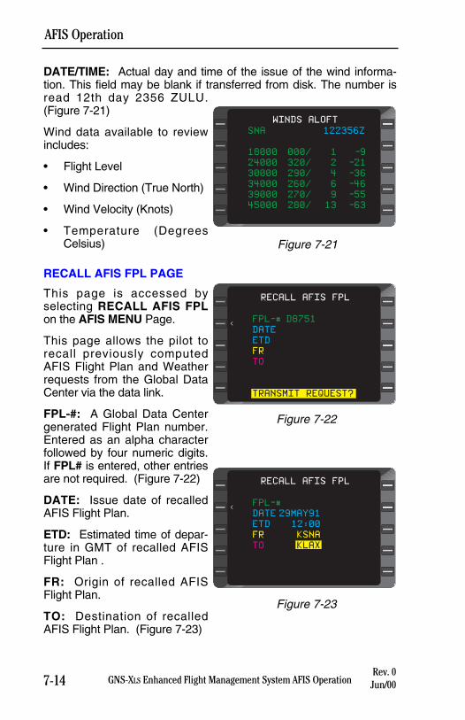
DATE/TIME: Actual day and time of the issue of the wind informa-tion. This field may be blank if transferred from disk. The number isread 12th day 2356 ZULU.(Figure 7-21)
Wind data available to reviewincludes:
• Flight Level
• Wind Direction (True North)
• Wind Velocity (Knots)
• Temperature (DegreesCelsius)
RECALL AFIS FPL PAGE
This page is accessed byselecting RECALL AFIS FPLon the AFIS MENU Page.
This page allows the pilot torecall previously computedAFIS Flight Plan and Weatherrequests from the Global DataCenter via the data link.
FPL-#: A Global Data Centergenerated Flight Plan number.Entered as an alpha characterfollowed by four numeric digits.If FPL# is entered, other entriesare not required. (Figure 7-22)
DATE: Issue date of recalledAFIS Flight Plan.
ETD: Estimated time of depar-ture in GMT of recalled AFISFlight Plan .
FR: Origin of recalled AFISFlight Plan.
TO: Destination of recalledAFIS Flight Plan. (Figure 7-23)
7-14 GNS-XLS Enhanced Flight Management System AFIS OperationRev. 0
Jun/00
AFIS Operation
SNA 122356Z
18000 000/ 1 -9
24000 320/ 2 -21
30000 290/ 4 -36
34000 260/ 6 -46
39000 270/ 9 -55
45000 280/ 13 -63
WINDS ALOFT
Figure 7-21
RECALL AFIS FPL
<FPL-# D8751
DATE
ETD
FR
TO
TRANSMIT REQUEST?
RECALL AFIS FPL
<FPL-#
DATE 29MAY91
ETD 12:00
FR KSNA
TO KLAX
Figure 7-22
Figure 7-23
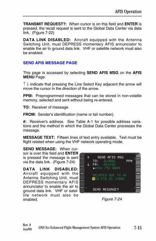
7-15GNS-XLS Enhanced Flight Management System AFIS OperationRev. 0Jun/00
AFIS Operation
TRANSMIT REQUEST?: When cursor is on this field and ENTER ispressed, the recall request is sent to the Global Data Center via datalink. (Figure 7-22)
DATA LINK DISABLED: Aircraft equipped with the AntennaSwitching Unit, must DEPRESS momentary AFIS annunciator toenable the air to ground data link. VHF or satellite network must alsobe enabled.
SEND AFIS MESSAGE PAGE
This page is accessed by selecting SEND AFIS MSG on the AFISMENU Page.
↑ ↓ indicate that pressing the Line Select Key adjacent the arrow willmove the cursor in the direction of the arrow.
PPM: Preprogrammed messages that can be stored in non-volatilememory, selected and sent without being re-entered.
TO: Receiver of message.
FROM: Sender's identification (name or tail number).
#: Receiver's address. See Table A-1 for possible address varia-tions and the method in which the Global Data Center processes themessage.
MESSAGE TEXT: Fifteen lines of text entry available. Text must beflight related when using the VHF network operating mode.
SEND MESSAGE: When cur-sor is over this field and ENTERis pressed the message is sentvia the data link. (Figure 7-24)
DATA LINK DISABLED:Aircraft equipped with theAntenna Switching Unit, mustDEPRESS momentary AFISannunciator to enable the air toground data link. VHF or satel-lite network must also beenabled.
TO: GLOBAL PPM
FR: N214SC
#:FAX 752 0604
DELAYED DUE TO WX
NEW ETA IS 1400Z
SEND MESSAGE?<
>
>
SEND AFIS MSG$
%
Figure 7-24
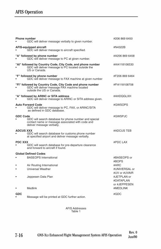
7-16 GNS-XLS Enhanced Flight Management System AFIS OperationRev. 0
Jun/00
AFIS Operation
Phone number #206 869 6450• GDC will deliver message verbally to given number.
AFIS-equipped aircraft #N4322B• GDC will deliver message to aircraft specified.
"A" followed by phone number #A206 869 6458• GDC will deliver message to PC at given number.
"AI" followed by Country Code, City Code, and phone number #AI4118106530• GDC will deliver message to PC located outside the
US or Canada.
"F" followed by phone number #F206 869 6464• GDC will deliver message to FAX machine at given number
"FI" followed by Country Code, City Code and phone number #FI4118108708• GDC will deliver message FAX machine located
outside the US or Canada.
"A" followed by ARINC or SITA address #AHDQGLXH• GDC will deliver message to ARINC or SITA address given.
Auto Forward Code #GWSOPS• GDC will deliver message to PC, FAX, or ARINC/SITA
as defined in GDC database.
GDC Code #GWSPJC• GDC will search database for phone number and special
contact name or message associated with code anddeliver message verbally.
ADCUS XXX #ADCUS TEB• GDC will search database for customs phone number
at specified airport and deliver message verbally.
PDC XXX #PDC LAX• GDC will search database for pre-departure clearance
and forward to aircraft if found.
Global Defined Codes• BASEOPS International #BASEOPS or
#BOPS• Air Routing International #ARC• Universal Weather #UNIVERSAL or
#UV or #UVAIR• Jeppesen Data Plan #JETPLAN or
#DATAPLAN or #JEPPESEN
• Medlink #MEDLINK
GDC #GDC• Message will be printed at GDC further action.
AFIS AddressesTable 1
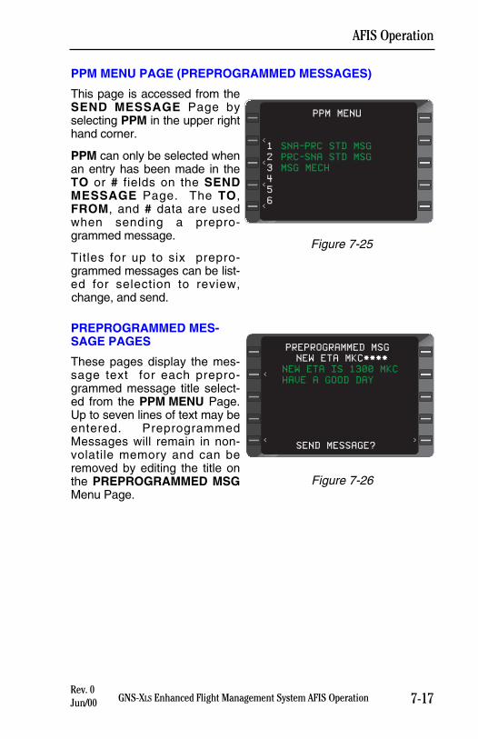
7-17GNS-XLS Enhanced Flight Management System AFIS OperationRev. 0Jun/00
AFIS Operation
PPM MENU PAGE (PREPROGRAMMED MESSAGES)
This page is accessed from theSEND MESSAGE Page byselecting PPM in the upper righthand corner.
PPM can only be selected whenan entry has been made in theTO or # fields on the SENDMESSAGE Page. The TO,FROM, and # data are usedwhen sending a prepro-grammed message.
Titles for up to six prepro-grammed messages can be list-ed for selection to review,change, and send.
PREPROGRAMMED MES-SAGE PAGES
These pages display the mes-sage text for each prepro-grammed message title select-ed from the PPM MENU Page.Up to seven lines of text may beentered. PreprogrammedMessages will remain in non-volatile memory and can beremoved by editing the title onthe PREPROGRAMMED MSGMenu Page.
1 SNA-PRC STD MSG
2 PRC-SNA STD MSG
3 MSG MECH
4
5
6
PPM MENU
<
<
<
<
Figure 7-25
NEW ETA MKC****
NEW ETA IS 1300 MKC
HAVE A GOOD DAY
SEND MESSAGE?
PREPROGRAMMED MSG
<
><
Figure 7-26
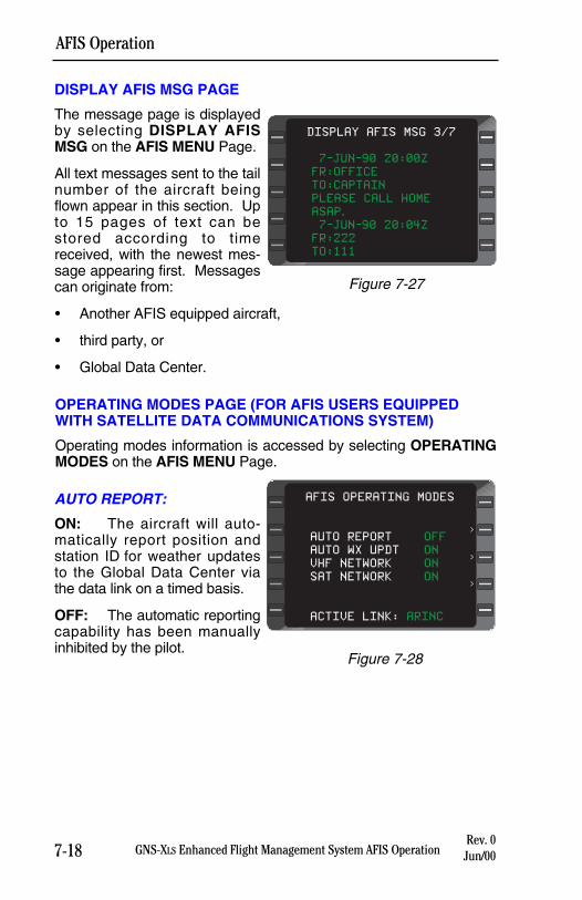
7-18 GNS-XLS Enhanced Flight Management System AFIS OperationRev. 0
Jun/00
AFIS Operation
DISPLAY AFIS MSG PAGE
The message page is displayedby selecting DISPLAY AFISMSG on the AFIS MENU Page.
All text messages sent to the tailnumber of the aircraft beingflown appear in this section. Upto 15 pages of text can bestored according to timereceived, with the newest mes-sage appearing first. Messagescan originate from:
• Another AFIS equipped aircraft,
• third party, or
• Global Data Center.
OPERATING MODES PAGE (FOR AFIS USERS EQUIPPEDWITH SATELLITE DATA COMMUNICATIONS SYSTEM)
Operating modes information is accessed by selecting OPERATINGMODES on the AFIS MENU Page.
AUTO REPORT:
ON: The aircraft will auto-matically report position andstation ID for weather updatesto the Global Data Center viathe data link on a timed basis.
OFF: The automatic reportingcapability has been manuallyinhibited by the pilot.
AUTO REPORT OFF
AUTO WX UPDT ON
VHF NETWORK ON
SAT NETWORK ON
ACTIVE LINK: ARINC
AFIS OPERATING MODES
>
>
>
Figure 7-28
7-JUN-90 20:00Z
FR:OFFICE
TO:CAPTAIN
PLEASE CALL HOME
ASAP.
7-JUN-90 20:04Z
FR:222
TO:111
DISPLAY AFIS MSG 3/7
Figure 7-27
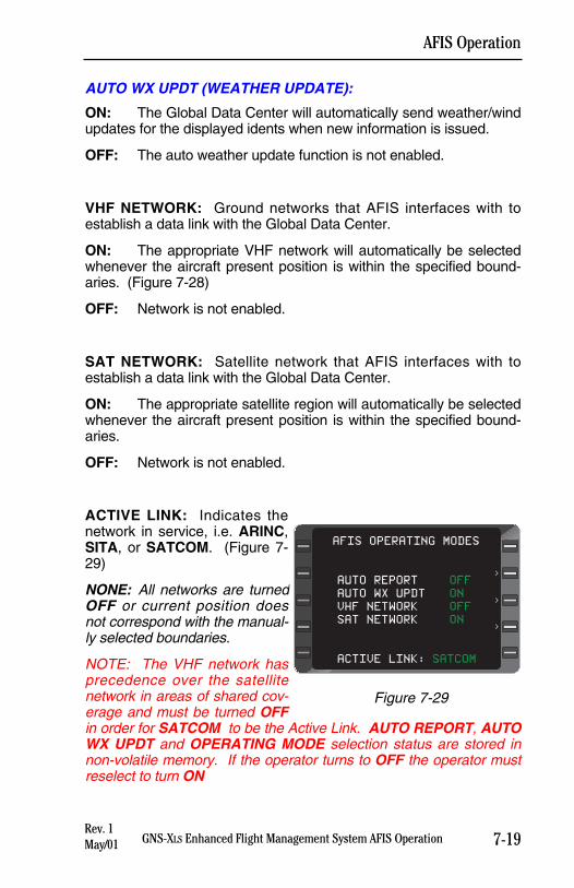
AUTO WX UPDT (WEATHER UPDATE):
ON: The Global Data Center will automatically send weather/windupdates for the displayed idents when new information is issued.
OFF: The auto weather update function is not enabled.
VHF NETWORK: Ground networks that AFIS interfaces with toestablish a data link with the Global Data Center.
ON: The appropriate VHF network will automatically be selectedwhenever the aircraft present position is within the specified bound-aries. (Figure 7-28)
OFF: Network is not enabled.
SAT NETWORK: Satellite network that AFIS interfaces with toestablish a data link with the Global Data Center.
ON: The appropriate satellite region will automatically be selectedwhenever the aircraft present position is within the specified bound-aries.
OFF: Network is not enabled.
ACTIVE LINK: Indicates thenetwork in service, i.e. ARINC,SITA, or SATCOM. (Figure 7-29)
NONE: All networks are turnedOFF or current position doesnot correspond with the manual-ly selected boundaries.
NOTE: The VHF network hasprecedence over the satellitenetwork in areas of shared cov-erage and must be turned OFFin order for SATCOM to be the Active Link. AUTO REPORT, AUTOWX UPDT and OPERATING MODE selection status are stored innon-volatile memory. If the operator turns to OFF the operator mustreselect to turn ON
7-19GNS-XLS Enhanced Flight Management System AFIS OperationRev. 1May/01
AFIS Operation
AUTO REPORT OFF
AUTO WX UPDT ON
VHF NETWORK OFF
SAT NETWORK ON
ACTIVE LINK: SATCOM
AFIS OPERATING MODES
>
>
>
Figure 7-29
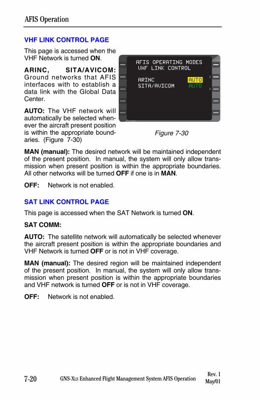
7-20 GNS-XLS Enhanced Flight Management System AFIS Operation
AFIS Operation
Rev. 1May/01
VHF LINK CONTROL PAGE
This page is accessed when theVHF Network is turned ON.
ARINC, SITA/AVICOM:Ground networks that AFISinterfaces with to establish adata link with the Global DataCenter.
AUTO: The VHF network willautomatically be selected when-ever the aircraft present positionis within the appropriate bound-aries. (Figure 7-30)
MAN (manual): The desired network will be maintained independentof the present position. In manual, the system will only allow trans-mission when present position is within the appropriate boundaries.All other networks will be turned OFF if one is in MAN.
OFF: Network is not enabled.
SAT LINK CONTROL PAGE
This page is accessed when the SAT Network is turned ON.
SAT COMM:
AUTO: The satellite network will automatically be selected wheneverthe aircraft present position is within the appropriate boundaries andVHF Network is turned OFF or is not in VHF coverage.
MAN (manual): The desired region will be maintained independentof the present position. In manual, the system will only allow trans-mission when present position is within the appropriate boundariesand VHF network is turned OFF or is not in VHF coverage.
OFF: Network is not enabled.
AFIS OPERATING MODES
>
>
VHF LINK CONTROL
ARINC AUTO
SITA/AVICOM AUTO
Figure 7-30
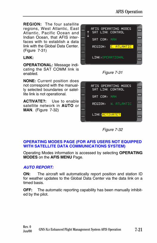
7-21GNS-XLS Enhanced Flight Management System AFIS OperationRev. 0Jun/00
AFIS Operation
REGION: The four satelliteregions, West Atlantic, EastAtlantic, Pacific Ocean andIndian Ocean, that AFIS inter-faces with to establish a datalink with the Global Data Center.(Figure 7-31)
LINK:
OPERATIONAL: Message indi-cating the SAT COMM link isenabled.
NONE: Current position doesnot correspond with the manual-ly selected boundaries or satel-lite link is not operational.
ACTIVATE?: Use to enablesatellite network in AUTO orMAN. (Figure 7-32)
OPERATING MODES PAGE (FOR AFIS USERS NOT EQUIPPEDWITH SATELLITE DATA COMMUNICATIONS SYSTEM)
Operating Modes information is accessed by selecting OPERATINGMODES on the AFIS MENU Page.
AUTO REPORT:
ON: The aircraft will automatically report position and station IDfor weather updates to the Global Data Center via the data link on atimed basis.
OFF: The automatic reporting capability has been manually inhibit-ed by the pilot.
AFIS OPERATING MODES
SAT LINK CONTROL
SAT COM: MAN
REGION: W. ATLANTIC
LINK:ACTIVATE?
Figure 7-32
AFIS OPERATING MODES
SAT LINK CONTROL
SAT COM: MAN
REGION: E. ATLANTIC
LINK:OPERATIONAL
$
%
Figure 7-31
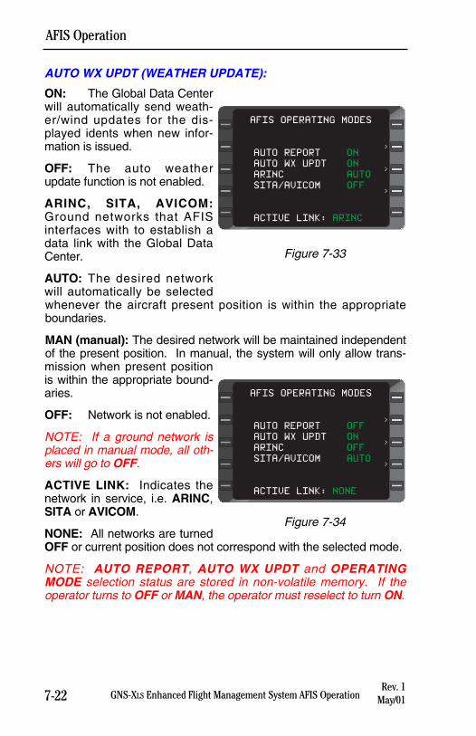
7-22 GNS-XLS Enhanced Flight Management System AFIS OperationRev. 1
May/01
AFIS Operation
AUTO WX UPDT (WEATHER UPDATE):
ON: The Global Data Centerwill automatically send weath-er/wind updates for the dis-played idents when new infor-mation is issued.
OFF: The auto weatherupdate function is not enabled.
ARINC, SITA, AVICOM:Ground networks that AFISinterfaces with to establish adata link with the Global DataCenter.
AUTO: The desired networkwill automatically be selectedwhenever the aircraft present position is within the appropriateboundaries.
MAN (manual): The desired network will be maintained independentof the present position. In manual, the system will only allow trans-mission when present positionis within the appropriate bound-aries.
OFF: Network is not enabled.
NOTE: If a ground network isplaced in manual mode, all oth-ers will go to OFF.
ACTIVE LINK: Indicates thenetwork in service, i.e. ARINC,SITA or AVICOM.
NONE: All networks are turnedOFF or current position does not correspond with the selected mode.
NOTE: AUTO REPORT, AUTO WX UPDT and OPERATINGMODE selection status are stored in non-volatile memory. If theoperator turns to OFF or MAN, the operator must reselect to turn ON.
AUTO REPORT OFF
AUTO WX UPDT ON
ARINC OFF
SITA/AVICOM AUTO
ACTIVE LINK: NONE
AFIS OPERATING MODES
>
>
>
Figure 7-34
AUTO REPORT ON
AUTO WX UPDT ON
ARINC AUTO
SITA/AVICOM OFF
ACTIVE LINK: ARINC
AFIS OPERATING MODES
>
>
>
Figure 7-33
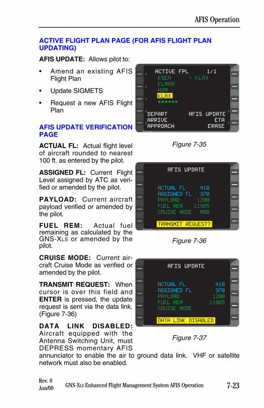
ACTIVE FLIGHT PLAN PAGE (FOR AFIS FLIGHT PLANUPDATING)
AFIS UPDATE: Allows pilot to:
• Amend an existing AFISFlight Plan
• Update SIGMETS
• Request a new AFIS FlightPlan
AFIS UPDATE VERIFICATIONPAGE
ACTUAL FL: Actual flight levelof aircraft rounded to nearest100 ft. as entered by the pilot.
ASSIGNED FL: Current FlightLevel assigned by ATC as veri-fied or amended by the pilot.
PAYLOAD: Current aircraftpayload verified or amended bythe pilot.
FUEL REM: Actual fuelremaining as calculated by theGNS-XLS or amended by thepilot.
CRUISE MODE: Current air-craft Cruise Mode as verified oramended by the pilot.
TRANSMIT REQUEST: Whencursor is over this field andENTER is pressed, the updaterequest is sent via the data link.(Figure 7-36)
DATA LINK DISABLED:Aircraft equipped with theAntenna Switching Unit, mustDEPRESS momentary AFISannunciator to enable the air to ground data link. VHF or satellitenetwork must also be enabled.
7-23GNS-XLS Enhanced Flight Management System AFIS OperationRev. 0Jun/00
AFIS Operation
>
KSEA - KLAX
ELMAA
HQM
KLAX
******
DEPART AFIS UPDATE
ARRIVE ETA
APPROACH ERASE
ACTIVE FPL 1/1
<
<
<
<
<
>
Figure 7-35
ACTUAL FL 410
ASSIGNED FL 370
PAYLOAD 1200
FUEL REM 11985
CRUISE MODE M80
TRANSMIT REQUEST?
AFIS UPDATE
Figure 7-36
ACTUAL FL 410
ASSIGNED FL 370
PAYLOAD 1200
FUEL REM 11985
CRUISE MODE
DATA LINK DISABLED
AFIS UPDATE
Figure 7-37
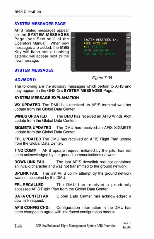
7-24 GNS-XLS Enhanced Flight Management System AFIS OperationRev. 0
Jun/00
AFIS Operation
SYSTEM MESSAGES PAGE
AFIS related messages appearon the SYSTEM MESSAGESPage (see Section 2 of theOperators Manual). When newmessages are added, the MSGKey will flash and a flashingasterisk will appear next to thenew message.
SYSTEM MESSAGES
ADVISORY:
The following are the advisory messages which pertain to AFIS andmay appear on the GNS-XLS SYSTEM MESSAGES Page.
SYSTEM MESSAGE EXPLANATION
WX UPDATED The DMU has received an AFIS terminal weatherupdate from the Global Data Center.
WINDS UPDATED The DMU has received an AFIS Winds Aloftupdate from the Global Data Center.
SIGMETS UPDATED The DMU has received an AFIS SIGMETSupdate from the Global Data Center.
FPL UPDATED The DMU has received an AFIS Flight Plan updatefrom the Global Data Center.
1 NO COMM AFIS update request initiated by the pilot has notbeen acknowledged by the ground communications network.
DOWNLINK FAIL The last AFIS downlink request containedan invalid character and was not transmitted to the ground network.
UPLINK FAIL The last AFIS uplink attempt by the ground networkwas not accepted by the DMU.
FPL RECALLED The DMU has received a previouslyaccessed AFIS Flight Plan from the Global Data Center.
DATA CENTER AK Global Data Center has acknowledged adownlink request.
AFIS CONFIG CHG. Configuration information in the DMU hasbeen changed to agree with interfaced configuration module
SYSTEM MESSAGES 1/1
*SEE AFIS MSG
*WX UPDATED
DATA CENTER AK
NDB- WW EXP 31MAY
Figure 7-38
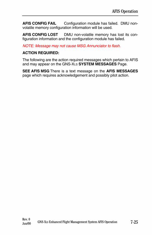
AFIS CONFIG FAIL Configuration module has failed. DMU non-volatile memory configuration information will be used.
AFIS CONFIG LOST DMU non-volatile memory has lost its con-figuration information and the configuration module has failed.
NOTE: Message may not cause MSG Annunciator to flash.
ACTION REQUIRED:
The following are the action required messages which pertain to AFISand may appear on the GNS-XLS SYSTEM MESSAGES Page.
SEE AFIS MSG There is a text message on the AFIS MESSAGESpage which requires acknowledgement and possibly pilot action.
7-25GNS-XLS Enhanced Flight Management System AFIS OperationRev. 0Jun/00
AFIS Operation
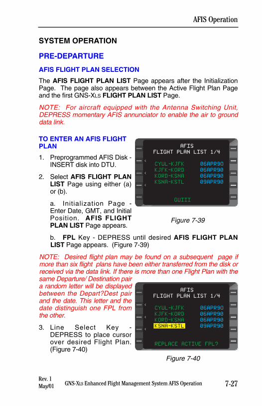
SYSTEM OPERATION
PRE-DEPARTURE
AFIS FLIGHT PLAN SELECTION
The AFIS FLIGHT PLAN LIST Page appears after the InitializationPage. The page also appears between the Active Flight Plan Pageand the first GNS-XLS FLIGHT PLAN LIST Page.
NOTE: For aircraft equipped with the Antenna Switching Unit,DEPRESS momentary AFIS annunciator to enable the air to grounddata link.
TO ENTER AN AFIS FLIGHTPLAN
1. Preprogrammed AFIS Disk -INSERT disk into DTU.
2. Select AFIS FLIGHT PLANLIST Page using either (a)or (b).
a. Initialization Page -Enter Date, GMT, and InitialPosition. AFIS FLIGHTPLAN LIST Page appears.
b. FPL Key - DEPRESS until desired AFIS FLIGHT PLANLIST Page appears. (Figure 7-39)
NOTE: Desired flight plan may be found on a subsequent page ifmore than six flight plans have been either transferred from the disk orreceived via the data link. If there is more than one Flight Plan with thesame Departure/ Destination paira random letter will be displayedbetween the Depart?Dest pairand the date. This letter and thedate distinguish one FPL fromthe other.
3. Line Select Key -DEPRESS to place cursorover desired Flight Plan.(Figure 7-40)
7-27GNS-XLS Enhanced Flight Management System AFIS OperationRev. 1May/01
AFIS Operation
FLIGHT PLAN LIST 1/4
CYUL-KJFK 06APR9O
KJFK-KORD 06APR90
KORD-KSNA 06APR90
KSNA-KSTL 09APR90
GUIII
AFIS
<
<
<
Figure 7-39
AFIS
FLIGHT PLAN LIST 1/4
CYUL-KJFK 06APR9O
KJFK-KORD 06APR90
KORD-KSNA 06APR90
KSNA-KSTL 09APR90
REPLACE ACTIVE FPL?
<
<
<
Figure 7-40
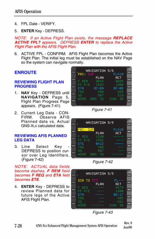
7-28 GNS-XLS Enhanced Flight Management System AFIS OperationRev. 0
Jun/00
AFIS Operation
4. FPL Date - VERIFY.
5. ENTER Key - DEPRESS.
NOTE: If an Active Flight Plan exists, the message REPLACEACTIVE FPL? appears. DEPRESS ENTER to replace the ActiveFlight Plan with the AFIS Flight Plan.
6. ACTIVE FPL - CONFIRM. AFIS Flight Plan becomes the ActiveFlight Plan. The initial leg must be established on the NAV Pageso the system can navigate normally.
ENROUTE
REVIEWING FLIGHT PLANPROGRESS
1. NAV Key - DEPRESS untilNAVIGATION Page 5,Flight Plan Progress Pageappears. (Figure 7-41)
2. Current Leg Data - CON-FIRM. Observe AFISPlanned data vs. ActualGNS-XLS calculated data.
REVIEWING AFIS PLANNEDLEG DATA
3. Line Select Key -DEPRESS to position cur-sor over Leg Identifiers.(Figure 7-42)
NOTE: ACTUAL data fieldsbecome dashes, F REM fieldbecomes F REQ and ETA fieldbecomes ETE.
4. ENTER Key - DEPRESS toreview Planned data forfuture legs of the ActiveAFIS Flight Plan.
NAVIGATION 5/5<
PRC: GUP FL410
PLAN ACT
F REM 9642 9685
FF P/E 1832 1800
ETA 02:09 02:08
TAS 488 485
GS 507 519
WIND 300/ 26 310/ 38
Figure 7-41
NAVIGATION 5/5<
PRC: GUP FL410
PLAN ACT
F REQ 1330 ------
FF P/E 1832 ----
ETE 0+22 -----
TAS 488 ---
GS 507 ---
WIND 300/ 26 ---/---
Figure 7-42
NAVIGATION 5/5<
DIR TO ICT FL---
PLAN ACT
F REQ ------ 9475
FF P/E ---- 1800
ETA ----- 03:17
TAS --- 485
GS --- 491
WIND ---/--- 310/ 38
Figure 7-43
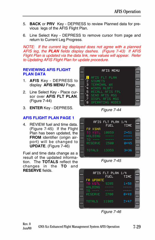
7-29GNS-XLS Enhanced Flight Management System AFIS OperationRev. 0Jun/00
AFIS Operation
5. BACK or PRV Key - DEPRESS to review Planned data for pre-vious legs of the AFIS Flight Plan.
6. Line Select Key - DEPRESS to remove cursor from page andreturn to Current Leg Progress.
NOTE: If the current leg displayed does not agree with a plannedAFIS leg, the PLAN fields display dashes. (Figure 7-43) If AFISFlight Plan is updated via the data link, new values will appear. Referto Updating AFIS Flight Plan for update procedure.
REVIEWING AFIS FLIGHTPLAN DATA
1. AFIS Key - DEPRESS todisplay AFIS MENU Page.
2. Line Select Key - Place cur-sor over AFIS FLT PLAN.(Figure 7-44)
3. ENTER Key - DEPRESS.
AFIS FLIGHT PLAN PAGE 1
4. REVIEW fuel and time data.(Figure 7-45) If the FlightPlan has been updated, theFROM identifier (origin air-port) will be changed toUPDATE. (Figure 7-46)
Fuel and time data change as aresult of the updated informa-tion. The TOTALS reflect thechanges in the TO andRESERVE fields.
AFIS MENU
<
<
<
<
1 AFIS FLT PLAN
2 SIGMETS
3 TERMINAL WX
4 WINDS ALOFT
5 RECALL AFIS FPL
6 SEND AFIS MSG
7 DISPL AFIS MSG
8 OPERATING MODES
Figure 7-44
FUEL TIME
FR KSNA
TO KSTL 10859 2+51
HOLDING ----- -----
TO ---- ----- -----
RESERVE 2500 0+45
TOTALS 13359 3+36
AFIS FLT PLAN 1/4
Figure 7-45
FUEL TIME
FR UPDATE
TO KSTL 9285 1+58
HOLDING ----- -----
TO ---- ----- -----
RESERVE 2700 0+49
TOTALS 11985 2+47
AFIS FLT PLAN 1/4
Figure 7-46
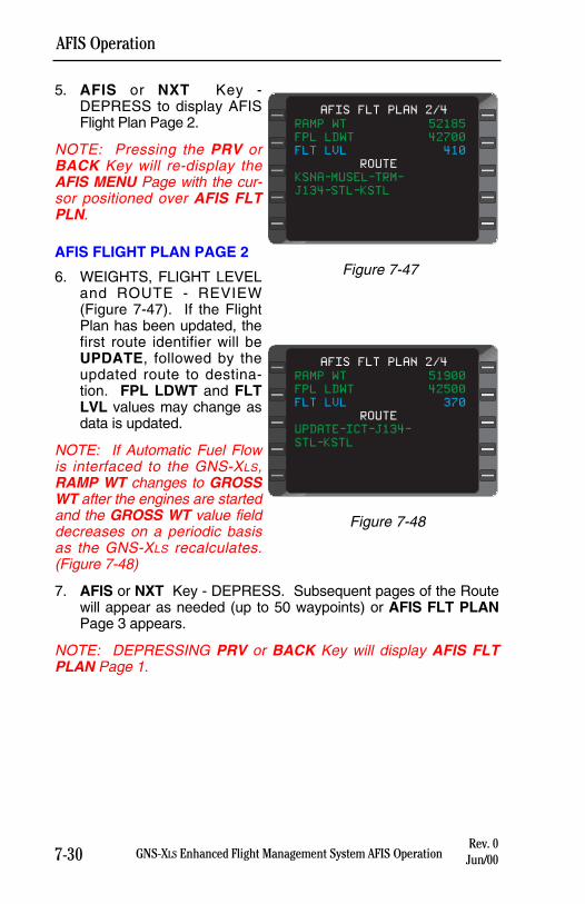
7-30 GNS-XLS Enhanced Flight Management System AFIS OperationRev. 0
Jun/00
AFIS Operation
5. AFIS or NXT Key -DEPRESS to display AFISFlight Plan Page 2.
NOTE: Pressing the PRV orBACK Key will re-display theAFIS MENU Page with the cur-sor positioned over AFIS FLTPLN.
AFIS FLIGHT PLAN PAGE 2
6. WEIGHTS, FLIGHT LEVELand ROUTE - REVIEW(Figure 7-47). If the FlightPlan has been updated, thefirst route identifier will beUPDATE, followed by theupdated route to destina-tion. FPL LDWT and FLTLVL values may change asdata is updated.
NOTE: If Automatic Fuel Flowis interfaced to the GNS-XLS,RAMP WT changes to GROSSWT after the engines are startedand the GROSS WT value fielddecreases on a periodic basisas the GNS-XLS recalculates.(Figure 7-48)
7. AFIS or NXT Key - DEPRESS. Subsequent pages of the Routewill appear as needed (up to 50 waypoints) or AFIS FLT PLANPage 3 appears.
NOTE: DEPRESSING PRV or BACK Key will display AFIS FLTPLAN Page 1.
RAMP WT 52185
FPL LDWT 42700
FLT LVL 410
ROUTE
KSNA-MUSEL-TRM-
J134-STL-KSTL
AFIS FLT PLAN 2/4
Figure 7-47
RAMP WT 51900
FPL LDWT 42500
FLT LVL 370
ROUTE
UPDATE-ICT-J134-
STL-KSTL
AFIS FLT PLAN 2/4
Figure 7-48
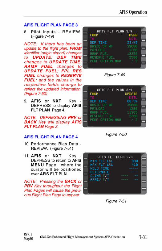
7-31GNS-XLS Enhanced Flight Management System AFIS OperationRev. 1May/01
AFIS Operation
AFIS FLIGHT PLAN PAGE 3
8. Pilot Inputs - REVIEW.(Figure 7-49)
NOTE: If there has been anupdate to the flight plan: FROMidentifier (origin airport) changesto UPDATE; DEP TIMEchanges to UPDATE TIME;RAMP FUEL changes toUPDATE FUEL; FPL RESFUEL changes to RESERVEFUEL; and the values in therespective fields change toreflect the updated information.(Figure 7-50)
9. AFIS or NXT Key -DEPRESS to display AFISFLT PLAN Page 4.
NOTE: DEPRESSING PRV orBACK Key will display AFISFLT PLAN Page 3.
AFIS FLIGHT PLAN PAGE 4
10. Performance Bias Data -REVIEW. (Figure 7-51)
11. AFIS or NXT Key -DEPRESS to return to AFISMENU Page, where thecursor will be positionedover AFIS FLT PLN.
NOTE: Pressing the BACK orPRV Key throughout the FlightPlan Pages will cause the previ-ous Flight Plan Page to appear.
FROM KSNA
TO KSTL
DEP TIME 23:45
BASIC OP WT 39000
PAYLOAD 1200
RAMP FUEL 13359
RESERVE FUEL 2500
PERF OPTION M80 / 2
AFIS FLT PLAN 3/4
Figure 7-49
FROM UPDATE
TO KSTL
DEP TIME 00:54
BASIC OP WT 39000
PAYLOAD 1200
RAMP FUEL 11985
RESERVE FUEL 2700
PERF OPTION M80 / 2
AFIS FLT PLAN 3/4
Figure 7-50
MIN FLT LVL 330
MAX FLT LVL 410
HOLD TIME -----
ALTERNATE ----
CLIMB F/T ---- --
ARRIV F/T ---- --
AFIS FLT PLAN 4/4
Figure 7-51
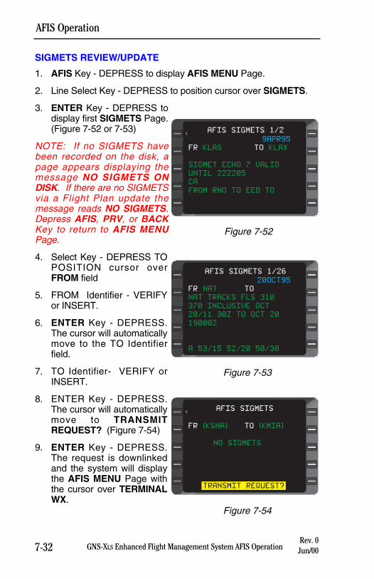
7-32 GNS-XLS Enhanced Flight Management System AFIS OperationRev. 0
Jun/00
AFIS Operation
SIGMETS REVIEW/UPDATE
1. AFIS Key - DEPRESS to display AFIS MENU Page.
2. Line Select Key - DEPRESS to position cursor over SIGMETS.
3. ENTER Key - DEPRESS todisplay first SIGMETS Page.(Figure 7-52 or 7-53)
NOTE: If no SIGMETS havebeen recorded on the disk, apage appears displaying themessage NO SIGMETS ONDISK. If there are no SIGMETSvia a Flight Plan update themessage reads NO SIGMETS.Depress AFIS, PRV, or BACKKey to return to AFIS MENUPage.
4. Select Key - DEPRESS TOPOSITION cursor overFROM field
5. FROM Identifier - VERIFYor INSERT.
6. ENTER Key - DEPRESS.The cursor will automaticallymove to the TO Identifierfield.
7. TO Identifier- VERIFY orINSERT.
8. ENTER Key - DEPRESS.The cursor will automaticallymove to TRANSMITREQUEST? (Figure 7-54)
9. ENTER Key - DEPRESS.The request is downlinkedand the system will displaythe AFIS MENU Page withthe cursor over TERMINALWX.
FR (KSNA) TO (KMIA)
NO SIGMETS
TRANSMIT REQUEST?
<AFIS SIGMETS
Figure 7-54
9APR95
FR KLAS TO KLAX
SIGMET ECHO 7 VALID
UNTIL 222205
CA
FROM RNO TO EED TO
AFIS SIGMETS 1/2<
Figure 7-52
20OCT95
FR NAT TO
NAT TRACKS FLS 310
370 INCLUSIVE OCT
20/11 30Z TO OCT 20
190002
A 53/15 52/20 50/30
AFIS SIGMETS 1/26
Figure 7-53
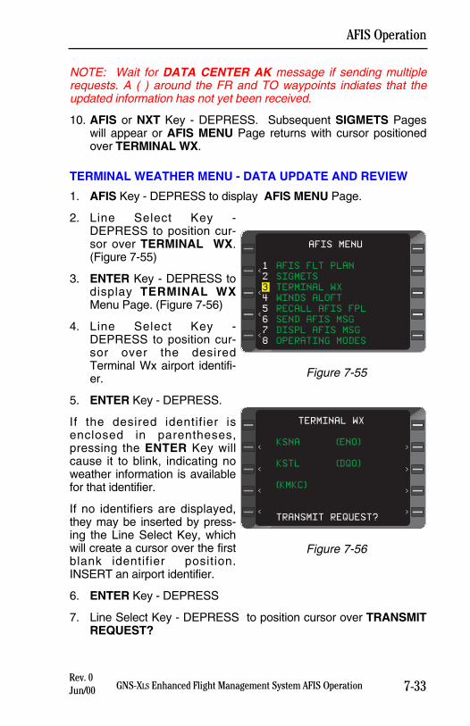
7-33GNS-XLS Enhanced Flight Management System AFIS OperationRev. 0Jun/00
AFIS Operation
NOTE: Wait for DATA CENTER AK message if sending multiplerequests. A ( ) around the FR and TO waypoints indiates that theupdated information has not yet been received.
10. AFIS or NXT Key - DEPRESS. Subsequent SIGMETS Pageswill appear or AFIS MENU Page returns with cursor positionedover TERMINAL WX.
TERMINAL WEATHER MENU - DATA UPDATE AND REVIEW
1. AFIS Key - DEPRESS to display AFIS MENU Page.
2. Line Select Key -DEPRESS to position cur-sor over TERMINAL WX.(Figure 7-55)
3. ENTER Key - DEPRESS todisplay TERMINAL WXMenu Page. (Figure 7-56)
4. Line Select Key -DEPRESS to position cur-sor over the desiredTerminal Wx airport identifi-er.
5. ENTER Key - DEPRESS.
If the desired identifier isenclosed in parentheses,pressing the ENTER Key willcause it to blink, indicating noweather information is availablefor that identifier.
If no identifiers are displayed,they may be inserted by press-ing the Line Select Key, whichwill create a cursor over the firstblank identifier position.INSERT an airport identifier.
6. ENTER Key - DEPRESS
7. Line Select Key - DEPRESS to position cursor over TRANSMITREQUEST?
AFIS MENU
<
<
<
<
1 AFIS FLT PLAN
2 SIGMETS
3 TERMINAL WX
4 WINDS ALOFT
5 RECALL AFIS FPL
6 SEND AFIS MSG
7 DISPL AFIS MSG
8 OPERATING MODES
Figure 7-55
<
<
<
<
KSNA (ENO)
KSTL (DQO)
(KMKC)
TRANSMIT REQUEST?
TERMINAL WX
>
>
>
>
Figure 7-56
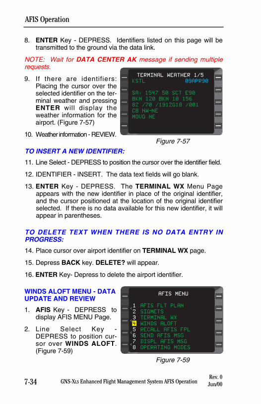
8. ENTER Key - DEPRESS. Identifiers listed on this page will betransmitted to the ground via the data link.
NOTE: Wait for DATA CENTER AK message if sending multiplerequests.
9. If there are identifiers:Placing the cursor over theselected identifier on the ter-minal weather and pressingENTER will display theweather information for theairport. (Figure 7-57)
10. Weather information - REVIEW.
TO INSERT A NEW IDENTIFIER:
11. Line Select - DEPRESS to position the cursor over the identifier field.
12. IDENTIFIER - INSERT. The data text fields will go blank.
13. ENTER Key - DEPRESS. The TERMINAL WX Menu Pageappears with the new identifier in place of the original identifier,and the cursor positioned at the location of the original identifierselected. If there is no data available for this new identifier, it willappear in parentheses.
TO DELETE TEXT WHEN THERE IS NO DATA ENTRY INPROGRESS:
14. Place cursor over airport identifier on TERMINAL WX page.
15. Depress BACK key. DELETE? will appear.
16. ENTER Key- Depress to delete the airport identifier.
WINDS ALOFT MENU - DATAUPDATE AND REVIEW
1. AFIS Key - DEPRESS todisplay AFIS MENU Page.
2. Line Select Key -DEPRESS to position cur-sor over WINDS ALOFT.(Figure 7-59)
7-34 GNS-XLS Enhanced Flight Management System AFIS OperationRev. 0
Jun/00
AFIS Operation
KSTL 09APR90
SA: 1547 50 SCT E90
BKN 120 BKN 10 156
82 /70 /1912G18 /001
CB NW-NE
MOVG NE
TERMINAL WEATHER 1/5
Figure 7-57
AFIS MENU
<
<
<
<
1 AFIS FLT PLAN
2 SIGMETS
3 TERMINAL WX
4 WINDS ALOFT
5 RECALL AFIS FPL
6 SEND AFIS MSG
7 DISPL AFIS MSG
8 OPERATING MODES
Figure 7-59
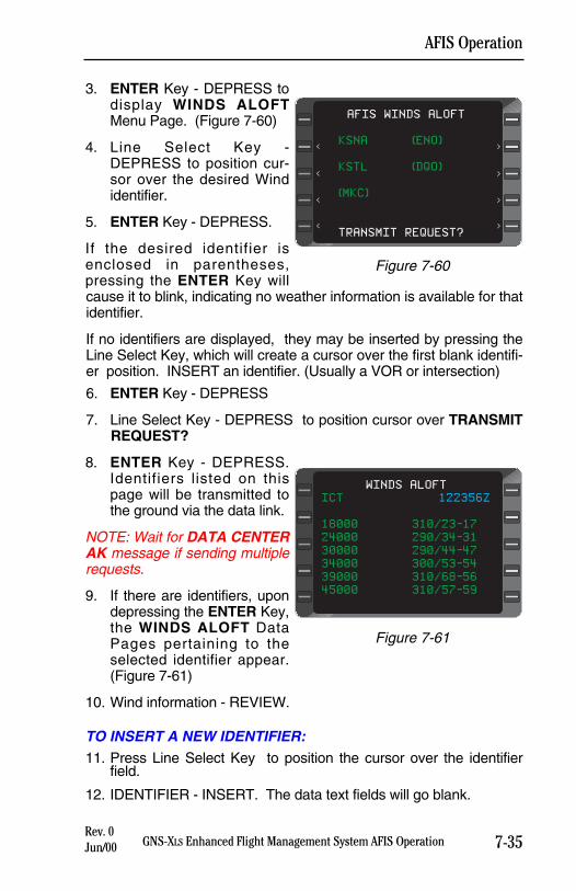
7-35GNS-XLS Enhanced Flight Management System AFIS OperationRev. 0Jun/00
AFIS Operation
3. ENTER Key - DEPRESS todisplay WINDS ALOFTMenu Page. (Figure 7-60)
4. Line Select Key -DEPRESS to position cur-sor over the desired Windidentifier.
5. ENTER Key - DEPRESS.
If the desired identifier isenclosed in parentheses,pressing the ENTER Key willcause it to blink, indicating no weather information is available for thatidentifier.
If no identifiers are displayed, they may be inserted by pressing theLine Select Key, which will create a cursor over the first blank identifi-er position. INSERT an identifier. (Usually a VOR or intersection)
6. ENTER Key - DEPRESS
7. Line Select Key - DEPRESS to position cursor over TRANSMITREQUEST?
8. ENTER Key - DEPRESS.Identifiers listed on thispage will be transmitted tothe ground via the data link.
NOTE: Wait for DATA CENTERAK message if sending multiplerequests.
9. If there are identifiers, upondepressing the ENTER Key,the WINDS ALOFT DataPages pertaining to theselected identifier appear.(Figure 7-61)
10. Wind information - REVIEW.
TO INSERT A NEW IDENTIFIER:11. Press Line Select Key to position the cursor over the identifier
field.
12. IDENTIFIER - INSERT. The data text fields will go blank.
<
<
<
<
KSNA (ENO)
KSTL (DQO)
(MKC)
TRANSMIT REQUEST?
AFIS WINDS ALOFT
>
>
>
>
Figure 7-60
ICT 122356Z
18000 310/23-17
24000 290/34-31
30000 290/44-47
34000 300/53-54
39000 310/68-56
45000 310/57-59
WINDS ALOFT
Figure 7-61
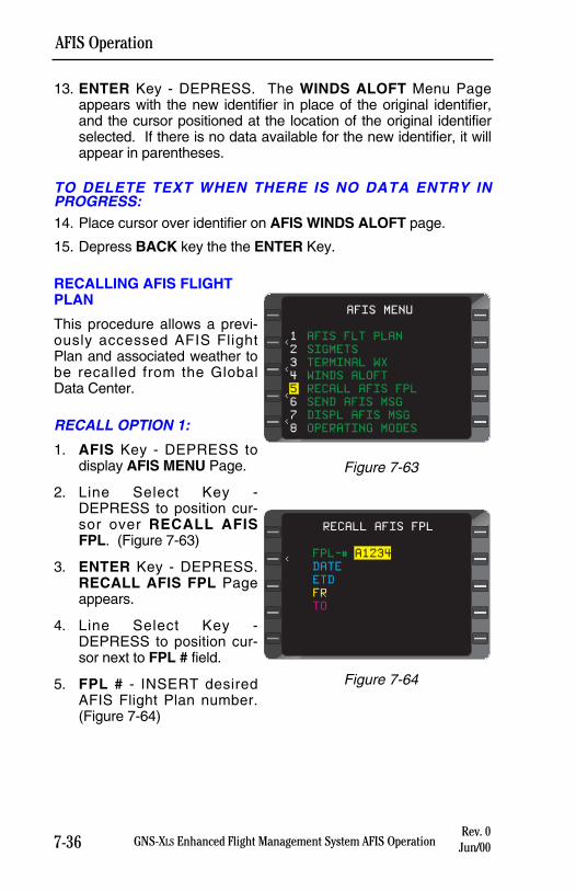
7-36 GNS-XLS Enhanced Flight Management System AFIS OperationRev. 0
Jun/00
AFIS Operation
13. ENTER Key - DEPRESS. The WINDS ALOFT Menu Pageappears with the new identifier in place of the original identifier,and the cursor positioned at the location of the original identifierselected. If there is no data available for the new identifier, it willappear in parentheses.
TO DELETE TEXT WHEN THERE IS NO DATA ENTRY INPROGRESS: 14. Place cursor over identifier on AFIS WINDS ALOFT page.
15. Depress BACK key the the ENTER Key.
RECALLING AFIS FLIGHTPLAN
This procedure allows a previ-ously accessed AFIS FlightPlan and associated weather tobe recalled from the GlobalData Center.
RECALL OPTION 1:
1. AFIS Key - DEPRESS todisplay AFIS MENU Page.
2. Line Select Key -DEPRESS to position cur-sor over RECALL AFISFPL. (Figure 7-63)
3. ENTER Key - DEPRESS.RECALL AFIS FPL Pageappears.
4. Line Select Key -DEPRESS to position cur-sor next to FPL # field.
5. FPL # - INSERT desiredAFIS Flight Plan number.(Figure 7-64)
AFIS MENU
<
<
<
<
1 AFIS FLT PLAN
2 SIGMETS
3 TERMINAL WX
4 WINDS ALOFT
5 RECALL AFIS FPL
6 SEND AFIS MSG
7 DISPL AFIS MSG
8 OPERATING MODES
Figure 7-63
RECALL AFIS FPL
<FPL-# A1234
DATE
ETD
FR
TO
Figure 7-64
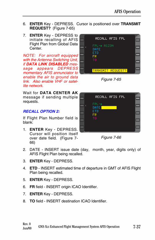
7-37GNS-XLS Enhanced Flight Management System AFIS OperationRev. 0Jun/00
AFIS Operation
6. ENTER Key - DEPRESS. Cursor is positioned over TRANSMITREQUEST? (Figure 7-65)
7. ENTER Key - DEPRESS toinitiate recalling of AFISFlight Plan from Global DataCenter.
NOTE: For aircraft equippedwith the Antenna Switching Unit,if DATA LINK DISABLED mes-sage appears DEPRESSmomentary AFIS annunciator toenable the air to ground datalink. Also enable VHF or satel-lite network.
Wait for DATA CENTER AKmessage if sending multiplerequests.
RECALL OPTION 2:
If Flight Plan Number field isblank:
1. ENTER Key - DEPRESS.Cursor will position itselfover date field. (Figure 7-66)
2. DATE - INSERT issue date (day, month, year, digits only) ofAFIS Flight Plan being recalled.
3. ENTER Key - DEPRESS.
4. ETD - INSERT estimated time of departure in GMT of AFIS FlightPlan being recalled.
5. ENTER Key - DEPRESS.
6. FR field - INSERT origin ICAO Identifier.
7. ENTER Key - DEPRESS.
8. TO field - INSERT destination ICAO Identifier.
RECALL AFIS FPL
<FPL-# A1234
DATE
ETD
FR
TO
TRANSMIT REQUEST?
Figure 7-65
RECALL AFIS FPL
<FPL-#
DATE
ETD
FR
TO
Figure 7-66
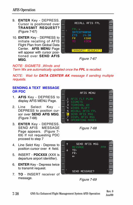
9. ENTER Key - DEPRESS.Cursor is positioned overTRANSMIT REQUEST?(Figure 7-67)
10. ENTER Key - DEPRESS toinitiate recalling of AFISFlight Plan from Global DataCenter. AFIS MENU Pagewill appear with cursor posi-tioned over SEND AFISMSG.
NOTE: SIGMETS ,Winds andTerm Wx are automatically updated once the FPL is recalled.
NOTE: Wait for DATA CENTER AK message if sending multiplerequests.
SENDING A TEXT MESSAGEOR PDC
1. AFIS Key - DEPRESS todisplay AFIS MENU Page.
2. Line Select Key -DEPRESS to position cur-sor over SEND AFIS MSG.(Figure 7-68)
3. ENTER Key - DEPRESS.SEND AFIS MESSAGEPage appears. (Figure 7-69) If not requesting PDCproceed to step 7
4. Line Selct Key - Depress toposition cursor over #: field.
5. INSERT - PDCXXX (XXX isdeparture airport identifier).
6. ENTER Key - Depress twiceto transmit request.
7. TO - INSERT receiver ofmessage.
7-38Rev. 0
Jun/00
AFIS Operation
GNS-XLS Enhanced Flight Management System AFIS Operation
RECALL AFIS FPL
<FPL-#
DATE07MAR90
ETD 14:30
FR KSNA
TO KDEN
TRANSMIT REQUEST?
Figure 7-67
AFIS MENU
<
<
<
<
1 AFIS FLT PLAN
2 SIGMETS
3 TERMINAL WX
4 WINDS ALOFT
5 RECALL AFIS FPL
6 SEND AFIS MSG
7 DISPL AFIS MSG
8 OPERATING MODES
Figure 7-68
SEND AFIS MSG
MESSAGE PPM
TO:
FR:
#:
SEND MESSAGE?< >
$
%
Figure 7-69
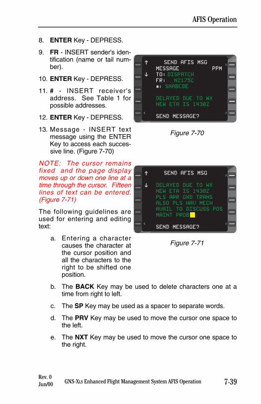
7-39GNS-XLS Enhanced Flight Management System AFIS OperationRev. 0Jun/00
AFIS Operation
8. ENTER Key - DEPRESS.
9. FR - INSERT sender's iden-tification (name or tail num-ber).
10. ENTER Key - DEPRESS.
11. # - INSERT receiver'saddress. See Table 1 forpossible addresses.
12. ENTER Key - DEPRESS.
13. Message - INSERT textmessage using the ENTERKey to access each succes-sive line. (Figure 7-70)
NOTE: The cursor remainsfixed and the page displaymoves up or down one line at atime through the cursor. Fifteenlines of text can be entered.(Figure 7-71)
The following guidelines areused for entering and editingtext:
a. Entering a charactercauses the character atthe cursor position andall the characters to theright to be shifted oneposition.
b. The BACK Key may be used to delete characters one at atime from right to left.
c. The SP Key may be used as a spacer to separate words.
d. The PRV Key may be used to move the cursor one space tothe left.
e. The NXT Key may be used to move the cursor one space tothe right.
SEND AFIS MSG
MESSAGE PPM
TO: DISPATCH
FR: N2175C
#: SNABCDE
DELAYED DUE TO WX
NEW ETA IS 1430Z
SEND MESSAGE?<
>
>
$
%
Figure 7-70
SEND AFIS MSG
DELAYED DUE TO WX
NEW ETA IS 1430Z
PLS ARR GND TRANS
ALSO PLS HAV MECH
AVAIL TO DISCUSS POS
MAINT PROB
SEND MESSAGE?<
>
>
$
%
Figure 7-71
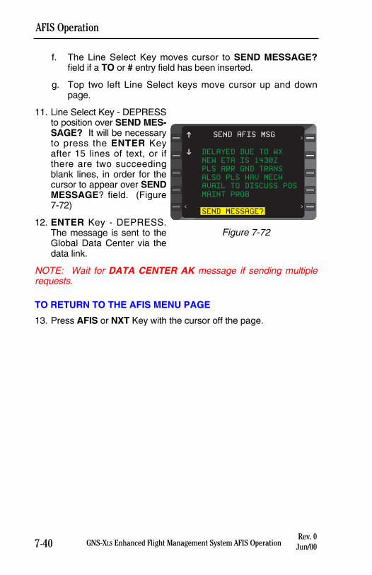
7-40 GNS-XLS Enhanced Flight Management System AFIS OperationRev. 0
Jun/00
AFIS Operation
f. The Line Select Key moves cursor to SEND MESSAGE?field if a TO or # entry field has been inserted.
g. Top two left Line Select keys move cursor up and downpage.
11. Line Select Key - DEPRESSto position over SEND MES-SAGE? It will be necessaryto press the ENTER Keyafter 15 lines of text, or ifthere are two succeedingblank lines, in order for thecursor to appear over SENDMESSAGE? field. (Figure7-72)
12. ENTER Key - DEPRESS.The message is sent to theGlobal Data Center via thedata link.
NOTE: Wait for DATA CENTER AK message if sending multiplerequests.
TO RETURN TO THE AFIS MENU PAGE
13. Press AFIS or NXT Key with the cursor off the page.
SEND AFIS MSG
DELAYED DUE TO WX
NEW ETA IS 1430Z
PLS ARR GND TRANS
ALSO PLS HAV MECH
AVAIL TO DISCUSS POS
MAINT PROB
SEND MESSAGE?<
>
>
$
%
Figure 7-72
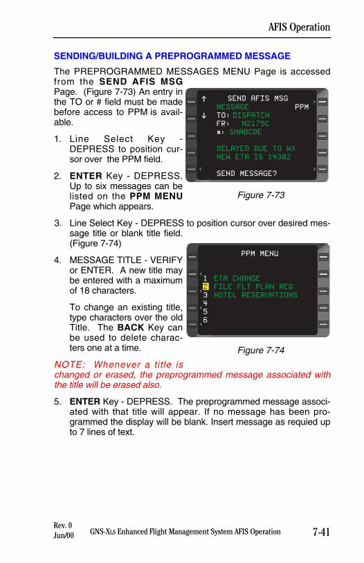
7-41GNS-XLS Enhanced Flight Management System AFIS OperationRev. 0Jun/00
AFIS Operation
SENDING/BUILDING A PREPROGRAMMED MESSAGE
The PREPROGRAMMED MESSAGES MENU Page is accessedfrom the SEND AFIS MSGPage. (Figure 7-73) An entry inthe TO or # field must be madebefore access to PPM is avail-able.
1. Line Select Key -DEPRESS to position cur-sor over the PPM field.
2. ENTER Key - DEPRESS.Up to six messages can belisted on the PPM MENUPage which appears.
3. Line Select Key - DEPRESS to position cursor over desired mes-sage title or blank title field.(Figure 7-74)
4. MESSAGE TITLE - VERIFYor ENTER. A new title maybe entered with a maximumof 18 characters.
To change an existing title,type characters over the oldTitle. The BACK Key canbe used to delete charac-ters one at a time.
NOTE: Whenever a title ischanged or erased, the preprogrammed message associated withthe title will be erased also.
5. ENTER Key - DEPRESS. The preprogrammed message associ-ated with that title will appear. If no message has been pro-grammed the display will be blank. Insert message as requied upto 7 lines of text.
SEND AFIS MSG
MESSAGE PPM
TO: DISPATCH
FR: N2175C
#: SNABCDE
DELAYED DUE TO WX
NEW ETA IS 1430Z
SEND MESSAGE?<
>
>
$
%
Figure 7-73
PPM MENU
<
<
<
<
1 ETA CHANGE
2 FILE FLT PLAN REQ
3 HOTEL RESERVATIONS
4
5
6
Figure 7-74
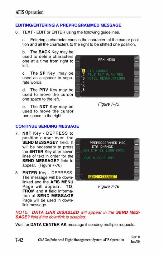
EDITING/ENTERING A PREPROGRAMMED MESSAGE
6. TEXT - EDIT or ENTER using the following guidelines.
a. Entering a character causes the character at the cursor posi-tion and all the characters to the right to be shifted one position.
b. The BACK Key may beused to delete charactersone at a time from right toleft.
c. The SP Key may beused as a spacer to sepa-rate words.
d. The PRV Key may beused to move the cursorone space to the left.
e. The NXT Key may beused to move the cursorone space to the right.
CONTINUE SENDING MESSAGE
7. NXT Key - DEPRESS toposition cursor over theSEND MESSAGE? field. Itwill be necessary to pressthe ENTER Key after sevenlines of text in order for theSEND MESSAGE? field toappear. (Figure 7-76)
8. ENTER Key - DEPRESS.The message will be down-linked and the AFIS MENUPage will appear. TO,FROM and # field informa-tion of SEND MESSAGEPage will be used in down-link message.
NOTE: DATA LINK DISABLED will appear in the SEND MES-SAGE? field if the downlink is disabled.
Wait for DATA CENTER AK message if sending multiple requests.
7-42 GNS-XLS Enhanced Flight Management System AFIS OperationRev. 0
Jun/00
AFIS Operation
PPM MENU
<
<
<
<
1 ETA CHANGE
2 FILE FLT PLAN REQ
3 HOTEL RESERVATIONS
4
5
6
Figure 7-75
ETA CHANGE
NEW ETA IS 1300 KPRC
HAVE A GOOD DAY
SEND MESSAGE?< >
PREPROGRAMMED MSG
<
Figure 7-76

7-43GNS-XLS Enhanced Flight Management System AFIS OperationRev. 0Jun/00
AFIS Operation
AFIS MESSAGES REVIEW
1. AFIS Key - DEPRESS todisplay AFIS MENU Page.
2. Line Select Key -DEPRESS to position cur-sor over DISPL AFIS MSG.(Figure 7-77)
3. ENTER Key - DEPRESS.DISPLAY AFIS MSG Pageappears.
4. MESSAGE - REVIEW.(Figure 7-78)
5. AFIS, NXT, PRV or BACKKey - DEPRESS.Subsequent messagepages appear or old AFISMENU Page returns withcursor positioned overOPERATING MODES.
NOTE: Messages will remain inthe system until the system ispowered off.
SELECTING OPERATING MODES (FOR AFIS USERSEQUIPPED WITH SATELLITE DATA COMMUNICATIONSSYSTEM)
AUTO REPORTING
When the system is initialized, the Automatic Reporting and Auto Wxupdate function will retain the status at aircraft shutdown. The follow-ing procedures allow the function to be turned OFF and back ON.
AFIS MENU
<
<
<
<
1 AFIS FLT PLAN
2 SIGMETS
3 TERMINAL WX
4 WINDS ALOFT
5 RECALL AFIS FPL
6 SEND AFIS MSG
7 DISPL AFIS MSG
8 OPERATING MODES
Figure 7-77
DISPATCH:
MESSAGE RECEIVED.
NEW ETA IS 1430Z.
TRANSPORTATION
ARRANGED.
DISPLAY AFIS MSG 1/1
Figure 7-78
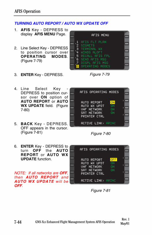
7-44 GNS-XLS Enhanced Flight Management System AFIS OperationRev. 1
May/01
AFIS Operation
TURNING AUTO REPORT / AUTO WX UPDATE OFF
1. AFIS Key - DEPRESS todisplay AFIS MENU Page.
2. Line Select Key - DEPRESSto position cursor overOPERATING MODES.(Figure 7-79)
3. ENTER Key - DEPRESS.
4. Line Select Key -DEPRESS to position cur-sor over ON option ofAUTO REPORT or AUTOWX UPDATE field. (Figure7-80)
5. BACK Key - DEPRESS.OFF appears in the cursor.(Figure 7-81)
6. ENTER Key - DEPRESS toturn OFF the AUTOREPORT or AUTO WXUPDATE function.
NOTE: If all networks are OFF,then AUTO REPORT andAUTO WX UPDATE will beOFF.
AFIS OPERATING MODES
AUTO REPORT ON
AUTO WX UPDT ON
VHF NETWORK ON
SAT NETWORK ON
PRINTER CTRL
ACTIVE LINK: ARINC
>
>
>
Figure 7-80
AFIS MENU
<
<
<
<
1 AFIS FLT PLAN
2 SIGMETS
3 TERMINAL WX
4 WINDS ALOFT
5 RECALL AFIS FPL
6 SEND AFIS MSG
7 DISPL AFIS MSG
8 OPERATING MODES
Figure 7-79
AFIS OPERATING MODES
AUTO REPORT OFF
AUTO WX UPDT ON
VHF NETWORK ON
SAT NETWORK ON
PRINTER CTRL
ACTIVE LINK: ARINC
>
>
>
Figure 7-81
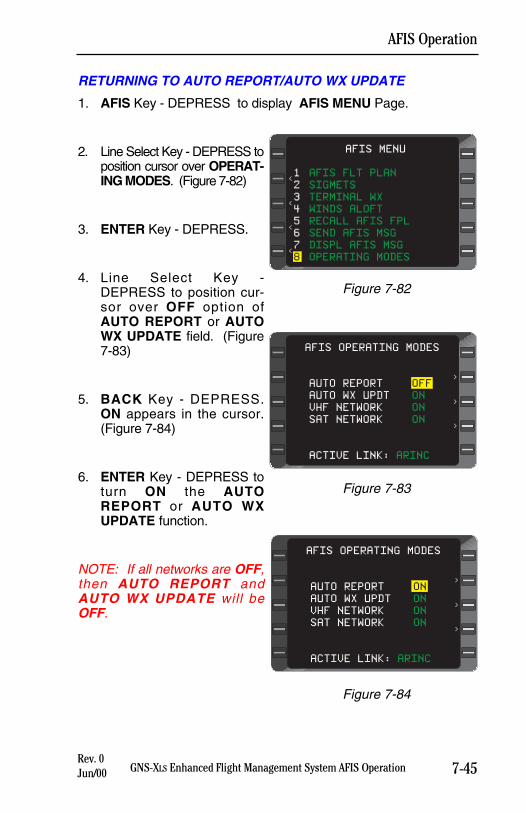
7-45GNS-XLS Enhanced Flight Management System AFIS OperationRev. 0Jun/00
AFIS Operation
RETURNING TO AUTO REPORT/AUTO WX UPDATE
1. AFIS Key - DEPRESS to display AFIS MENU Page.
2. Line Select Key - DEPRESS toposition cursor over OPERAT-ING MODES. (Figure 7-82)
3. ENTER Key - DEPRESS.
4. Line Select Key -DEPRESS to position cur-sor over OFF option ofAUTO REPORT or AUTOWX UPDATE field. (Figure7-83)
5. BACK Key - DEPRESS.ON appears in the cursor.(Figure 7-84)
6. ENTER Key - DEPRESS toturn ON the AUTOREPORT or AUTO WXUPDATE function.
NOTE: If all networks are OFF,then AUTO REPORT andAUTO WX UPDATE will beOFF.
AFIS MENU
<
<
<
<
1 AFIS FLT PLAN
2 SIGMETS
3 TERMINAL WX
4 WINDS ALOFT
5 RECALL AFIS FPL
6 SEND AFIS MSG
7 DISPL AFIS MSG
8 OPERATING MODES
Figure 7-82
AFIS OPERATING MODES
AUTO REPORT OFF
AUTO WX UPDT ON
VHF NETWORK ON
SAT NETWORK ON
ACTIVE LINK: ARINC
>
>
>
Figure 7-83
AFIS OPERATING MODES
AUTO REPORT ON
AUTO WX UPDT ON
VHF NETWORK ON
SAT NETWORK ON
ACTIVE LINK: ARINC
>
>
>
Figure 7-84
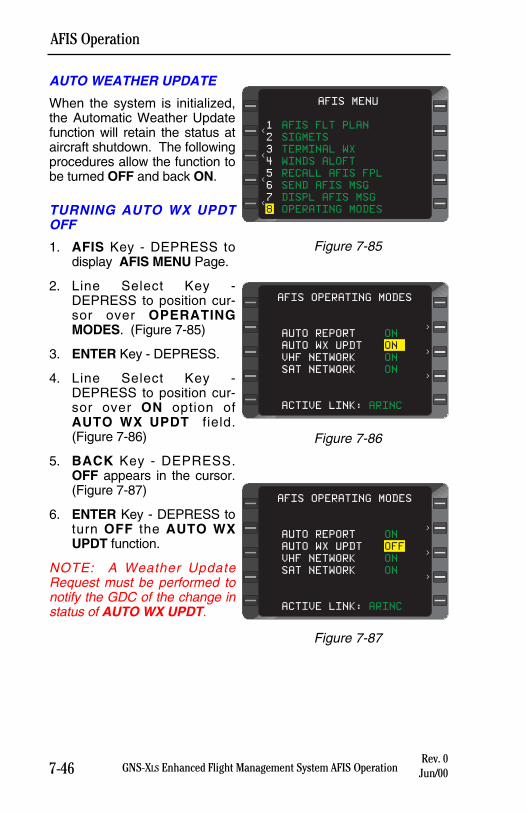
7-46 GNS-XLS Enhanced Flight Management System AFIS OperationRev. 0
Jun/00
AFIS Operation
AUTO WEATHER UPDATE
When the system is initialized,the Automatic Weather Updatefunction will retain the status ataircraft shutdown. The followingprocedures allow the function tobe turned OFF and back ON.
TURNING AUTO WX UPDTOFF
1. AFIS Key - DEPRESS todisplay AFIS MENU Page.
2. Line Select Key -DEPRESS to position cur-sor over OPERATINGMODES. (Figure 7-85)
3. ENTER Key - DEPRESS.
4. Line Select Key -DEPRESS to position cur-sor over ON option ofAUTO WX UPDT field.(Figure 7-86)
5. BACK Key - DEPRESS.OFF appears in the cursor.(Figure 7-87)
6. ENTER Key - DEPRESS toturn OFF the AUTO WXUPDT function.
NOTE: A Weather UpdateRequest must be performed tonotify the GDC of the change instatus of AUTO WX UPDT.
AFIS MENU
<
<
<
<
1 AFIS FLT PLAN
2 SIGMETS
3 TERMINAL WX
4 WINDS ALOFT
5 RECALL AFIS FPL
6 SEND AFIS MSG
7 DISPL AFIS MSG
8 OPERATING MODES
Figure 7-85
AFIS OPERATING MODES
AUTO REPORT ON
AUTO WX UPDT ON
VHF NETWORK ON
SAT NETWORK ON
ACTIVE LINK: ARINC
>
>
>
Figure 7-86
AFIS OPERATING MODES
AUTO REPORT ON
AUTO WX UPDT OFF
VHF NETWORK ON
SAT NETWORK ON
ACTIVE LINK: ARINC
>
>
>
Figure 7-87
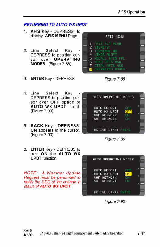
7-47GNS-XLS Enhanced Flight Management System AFIS OperationRev. 0Jun/00
AFIS Operation
RETURNING TO AUTO WX UPDT
1. AFIS Key - DEPRESS todisplay AFIS MENU Page.
2. Line Select Key -DEPRESS to position cur-sor over OPERATINGMODES. (Figure 7-88)
3. ENTER Key - DEPRESS.
4. Line Select Key -DEPRESS to position cur-sor over OFF option ofAUTO WX UPDT field.(Figure 7-89)
5. BACK Key - DEPRESS.ON appears in the cursor.(Figure 7-90)
6. ENTER Key - DEPRESS toturn ON the AUTO WXUPDT function.
NOTE: A Weather UpdateRequest must be performed tonotify the GDC of the change instatus of AUTO WX UPDT.
AFIS MENU
<
<
<
<
1 AFIS FLT PLAN
2 SIGMETS
3 TERMINAL WX
4 WINDS ALOFT
5 RECALL AFIS FPL
6 SEND AFIS MSG
7 DISPL AFIS MSG
8 OPERATING MODES
Figure 7-88
AFIS OPERATING MODES
AUTO REPORT OFF
AUTO WX UPDT OFF
VHF NETWORK ON
SAT NETWORK ON
ACTIVE LINK: ARINC
>
>
>
Figure 7-89
AFIS OPERATING MODES
AUTO REPORT OFF
AUTO WX UPDT ON
VHF NETWORK ON
SAT NETWORK ON
ACTIVE LINK: ARINC
>
>
>
Figure 7-90
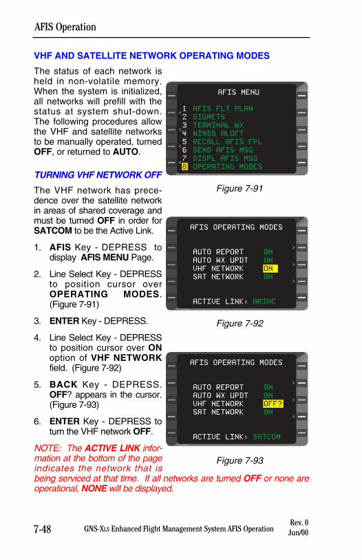
7-48 GNS-XLS Enhanced Flight Management System AFIS OperationRev. 0
Jun/00
AFIS Operation
VHF AND SATELLITE NETWORK OPERATING MODES
The status of each network isheld in non-volatile memory.When the system is initialized,all networks will prefill with thestatus at system shut-down.The following procedures allowthe VHF and satellite networksto be manually operated, turnedOFF, or returned to AUTO.
TURNING VHF NETWORK OFF
The VHF network has prece-dence over the satellite networkin areas of shared coverage andmust be turned OFF in order forSATCOM to be the Active Link.
1. AFIS Key - DEPRESS todisplay AFIS MENU Page.
2. Line Select Key - DEPRESSto position cursor overOPERATING MODES.(Figure 7-91)
3. ENTER Key - DEPRESS.
4. Line Select Key - DEPRESSto position cursor over ONoption of VHF NETWORKfield. (Figure 7-92)
5. BACK Key - DEPRESS.OFF? appears in the cursor.(Figure 7-93)
6. ENTER Key - DEPRESS toturn the VHF network OFF.
NOTE: The ACTIVE LINK infor-mation at the bottom of the pageindicates the network that isbeing serviced at that time. If all networks are turned OFF or none areoperational, NONE will be displayed.
AFIS OPERATING MODES
AUTO REPORT ON
AUTO WX UPDT ON
VHF NETWORK OFF?
SAT NETWORK ON
ACTIVE LINK: SATCOM
>
>
>
Figure 7-93
AFIS OPERATING MODES
AUTO REPORT ON
AUTO WX UPDT ON
VHF NETWORK ON
SAT NETWORK ON
ACTIVE LINK: ARINC
>
>
>
Figure 7-92
AFIS MENU
<
<
<
<
1 AFIS FLT PLAN
2 SIGMETS
3 TERMINAL WX
4 WINDS ALOFT
5 RECALL AFIS FPL
6 SEND AFIS MSG
7 DISPL AFIS MSG
8 OPERATING MODES
Figure 7-91
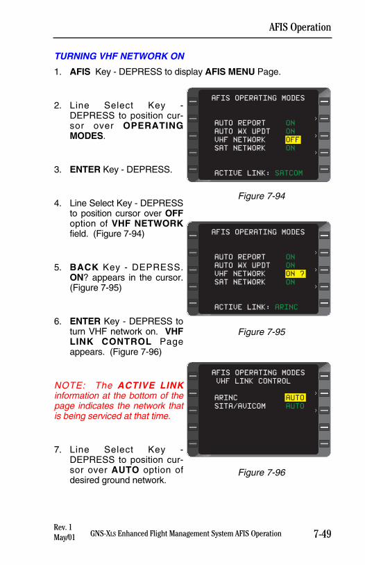
7-49GNS-XLS Enhanced Flight Management System AFIS OperationRev. 1May/01
AFIS Operation
TURNING VHF NETWORK ON
1. AFIS Key - DEPRESS to display AFIS MENU Page.
2. Line Select Key -DEPRESS to position cur-sor over OPERATINGMODES.
3. ENTER Key - DEPRESS.
4. Line Select Key - DEPRESSto position cursor over OFFoption of VHF NETWORKfield. (Figure 7-94)
5. BACK Key - DEPRESS.ON? appears in the cursor.(Figure 7-95)
6. ENTER Key - DEPRESS toturn VHF network on. VHFLINK CONTROL Pageappears. (Figure 7-96)
NOTE: The ACTIVE LINKinformation at the bottom of thepage indicates the network thatis being serviced at that time.
7. Line Select Key -DEPRESS to position cur-sor over AUTO option ofdesired ground network.
AFIS OPERATING MODES
AUTO REPORT ON
AUTO WX UPDT ON
VHF NETWORK OFF
SAT NETWORK ON
ACTIVE LINK: SATCOM
>
>
>
Figure 7-94
AFIS OPERATING MODES
AUTO REPORT ON
AUTO WX UPDT ON
VHF NETWORK ON ?
SAT NETWORK ON
ACTIVE LINK: ARINC
>
>
>
Figure 7-95
AFIS OPERATING MODES
>
>
VHF LINK CONTROL
ARINC AUTO
SITA/AVICOM AUTO
Figure 7-96
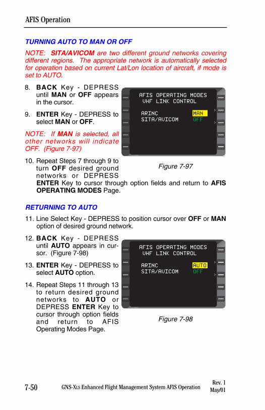
7-50 GNS-XLS Enhanced Flight Management System AFIS OperationRev. 1
May/01
AFIS Operation
TURNING AUTO TO MAN OR OFF
NOTE: SITA/AVICOM are two different ground networks coveringdifferent regions. The appropriate network is automatically selectedfor operation based on current Lat/Lon location of aircraft, if mode isset to AUTO.
8. BACK Key - DEPRESSuntil MAN or OFF appearsin the cursor.
9. ENTER Key - DEPRESS toselect MAN or OFF.
NOTE: If MAN is selected, allother networks will indicateOFF. (Figure 7-97)
10. Repeat Steps 7 through 9 toturn OFF desired groundnetworks or DEPRESSENTER Key to cursor through option fields and return to AFISOPERATING MODES Page.
RETURNING TO AUTO
11. Line Select Key - DEPRESS to position cursor over OFF or MANoption of desired ground network.
12. BACK Key - DEPRESSuntil AUTO appears in cur-sor. (Figure 7-98)
13. ENTER Key - DEPRESS toselect AUTO option.
14. Repeat Steps 11 through 13to return desired groundnetworks to AUTO orDEPRESS ENTER Key tocursor through option fieldsand return to AFISOperating Modes Page.
AFIS OPERATING MODES
>
>
VHF LINK CONTROL
ARINC AUTO
SITA/AVICOM OFF
Figure 7-98
AFIS OPERATING MODES
>
>
VHF LINK CONTROL
ARINC MAN
SITA/AVICOM OFF
Figure 7-97
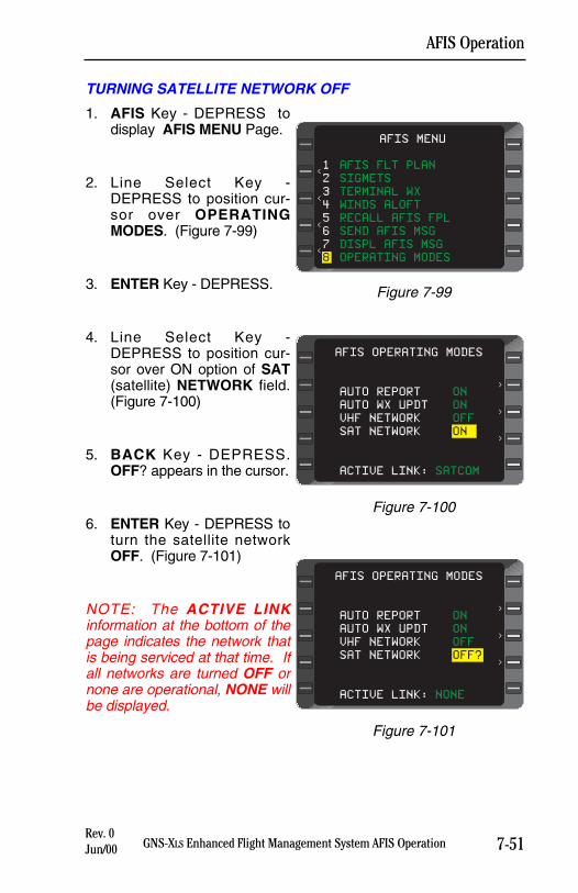
7-51GNS-XLS Enhanced Flight Management System AFIS OperationRev. 0Jun/00
AFIS Operation
TURNING SATELLITE NETWORK OFF
1. AFIS Key - DEPRESS todisplay AFIS MENU Page.
2. Line Select Key -DEPRESS to position cur-sor over OPERATINGMODES. (Figure 7-99)
3. ENTER Key - DEPRESS.
4. Line Select Key -DEPRESS to position cur-sor over ON option of SAT(satellite) NETWORK field.(Figure 7-100)
5. BACK Key - DEPRESS.OFF? appears in the cursor.
6. ENTER Key - DEPRESS toturn the satellite networkOFF. (Figure 7-101)
NOTE: The ACTIVE LINKinformation at the bottom of thepage indicates the network thatis being serviced at that time. Ifall networks are turned OFF ornone are operational, NONE willbe displayed.
AFIS MENU
<
<
<
<
1 AFIS FLT PLAN
2 SIGMETS
3 TERMINAL WX
4 WINDS ALOFT
5 RECALL AFIS FPL
6 SEND AFIS MSG
7 DISPL AFIS MSG
8 OPERATING MODES
Figure 7-99
AFIS OPERATING MODES
AUTO REPORT ON
AUTO WX UPDT ON
VHF NETWORK OFF
SAT NETWORK ON
ACTIVE LINK: SATCOM
>
>
>
Figure 7-100
AFIS OPERATING MODES
AUTO REPORT ON
AUTO WX UPDT ON
VHF NETWORK OFF
SAT NETWORK OFF?
ACTIVE LINK: NONE
>
>
>
Figure 7-101
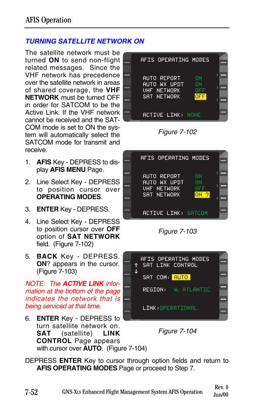
7-52 GNS-XLS Enhanced Flight Management System AFIS OperationRev. 0
Jun/00
AFIS Operation
TURNING SATELLITE NETWORK ON
The satellite network must beturned ON to send non-flightrelated messages. Since theVHF network has precedenceover the satellite network in areasof shared coverage, the VHFNETWORK must be turned OFFin order for SATCOM to be theActive Link. If the VHF networkcannot be received and the SAT-COM mode is set to ON the sys-tem will automatically select theSATCOM mode for transmit andreceive.
1. AFIS Key - DEPRESS to dis-play AFIS MENU Page.
2. Line Select Key - DEPRESSto position cursor overOPERATING MODES.
3. ENTER Key - DEPRESS.
4. Line Select Key - DEPRESSto position cursor over OFFoption of SAT NETWORKfield. (Figure 7-102)
5. BACK Key - DEPRESS.ON? appears in the cursor.(Figure 7-103)
NOTE: The ACTIVE LINK infor-mation at the bottom of the pageindicates the network that isbeing serviced at that time.
6. ENTER Key - DEPRESS toturn satellite network on.SAT (satellite) LINKCONTROL Page appearswith cursor over AUTO. (Figure 7-104)
DEPRESS ENTER Key to cursor through option fields and return toAFIS OPERATING MODES Page or proceed to Step 7.
AFIS OPERATING MODES
SAT LINK CONTROL
SAT COM: AUTO
REGION: W. ATLANTIC
LINK:OPERATIONAL
$
%
Figure 7-104
AFIS OPERATING MODES
AUTO REPORT ON
AUTO WX UPDT ON
VHF NETWORK OFF
SAT NETWORK ON ?
ACTIVE LINK: SATCOM
>
>
>
Figure 7-103
AFIS OPERATING MODES
AUTO REPORT ON
AUTO WX UPDT ON
VHF NETWORK OFF
SAT NETWORK OFF
ACTIVE LINK: NONE
>
>
>
Figure 7-102
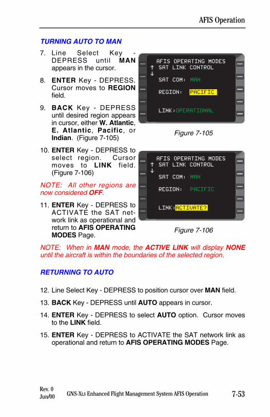
7-53GNS-XLS Enhanced Flight Management System AFIS OperationRev. 0Jun/00
AFIS Operation
TURNING AUTO TO MAN
7. Line Select Key -DEPRESS until MANappears in the cursor.
8. ENTER Key - DEPRESS.Cursor moves to REGIONfield.
9. BACK Key - DEPRESSuntil desired region appearsin cursor, either W. Atlantic,E. Atlantic, Pacific, orIndian. (Figure 7-105)
10. ENTER Key - DEPRESS toselect region. Cursormoves to LINK field.(Figure 7-106)
NOTE: All other regions arenow considered OFF.
11. ENTER Key - DEPRESS toACTIVATE the SAT net-work link as operational andreturn to AFIS OPERATINGMODES Page.
NOTE: When in MAN mode, the ACTIVE LINK will display NONEuntil the aircraft is within the boundaries of the selected region.
RETURNING TO AUTO
12. Line Select Key - DEPRESS to position cursor over MAN field.
13. BACK Key - DEPRESS until AUTO appears in cursor.
14. ENTER Key - DEPRESS to select AUTO option. Cursor movesto the LINK field.
15. ENTER Key - DEPRESS to ACTIVATE the SAT network link asoperational and return to AFIS OPERATING MODES Page.
AFIS OPERATING MODES
SAT LINK CONTROL
SAT COM: MAN
REGION: PACIFIC
LINK:OPERATIONAL
$
%
Figure 7-105
AFIS OPERATING MODES
SAT LINK CONTROL
SAT COM: MAN
REGION: PACIFIC
LINK:ACTIVATE?
$
%
Figure 7-106
PRINTER CTRL
The AFIS DMU has two RS-232 printer interfaces. Users may printmessages or weather to either or both printer ports. Automatic print-ing is also available. Controls for these options, as well as Auto FormFeed control, are accessed on the PRINTER CONTROL page.Access the PRINTER CONTROL page by line selecting the PRINT-ER CTRL field on the OPERATING MODES page and pressingENTER.
MESSAGE DEST
The Message Destination field is used to assign the printer port thatwill be used when messages are printed. Messages can be sent toprinter port 1 (PRT1), printer port 2 (PRT2), or BOTH.
1. AFIS key - DEPRESS to display AFIS MENU page.
2. Line Select Key - DEPRESS to position cursor over OPERATINGMODES.
3. ENTER Key - DEPRESS.
4. Line Select Key - DEPRESS to position cursor over the PRINT-ER CTRL field. SEL will appear in the field.
5. ENTER Key - DEPRESS to access the PRINTER CONTROLpage.
6. Line Select Key - DEPRESS to position cursor over MESSAGEDEST.
7. BACK Key - DEPRESS to cycle destination field between PRT1,PRT2, and BOTH.
8. ENTER Key - DEPRESS to set Message Destination field to itspresent value (PRT1, PRT2, or BOTH.)
WEATHER DEST
The Weather Destination field is used to assign the printer port thatwill be used when weather is printed. Weather can be sent to printerport 1 (PRT1), printer port 2 (PRT2), or BOTH.
1. AFIS key - DEPRESS to display AFIS MENU page.
2. Line Select Key - DEPRESS to position cursor over OPERATINGMODES.
7-54 GNS-XLS Enhanced Flight Management System AFIS OperationRev. 1
May/01
AFIS Operation
3. ENTER Key - DEPRESS.
4. Line Select Key - DEPRESS to position cursor over SEL optionof PRINTER CTRL field.
5. ENTER Key - DEPRESS to access the PRINTER CONTROLpage.
6. Line Select Key - DEPRESS to position cursor over WEATHERDEST.
7. BACK Key - DEPRESS to cycle destination field between PRT1,PRT2, and BOTH.
8. ENTER Key - DEPRESS to set Message Destination field to itspresent value (PRT1, PRT2, or BOTH.)
AUTO FORM FEED
The Auto Form Feed option, when set to YES, will cause the printerto Form Feed, or eject the page, after each message or weatherreport is printed. Setting the Auto Form Feed option to NO will printmessages and weather reports on the same page until the page isfull, then eject the page.
1. AFIS key - DEPRESS to display AFIS MENU page.
2. Line Select Key - DEPRESS to position cursor over OPERATINGMODES.
3. ENTER Key - DEPRESS.
4. Line Select Key - DEPRESS to position cursor over SEL optionof PRINTER CTRL field.
5. ENTER Key - DEPRESS to access the PRINTER CONTROLpage.
6. Line Select Key - DEPRESS to position cursor over AUTOFORM FEED.
7. BACK Key - DEPRESS to toggle Auto Form Feed optionbetween YES and NO.
8. ENTER Key - DEPRESS to set Auto Form Feed to its presentvalue (YES or NO.)
7-55GNS-XLS Enhanced Flight Management System AFIS OperationRev. 1May/01
AFIS Operation
AUTO PRINT MSG
The Auto Print Message field is used to select or deselect the auto-matic printing of messages. If AUTO PRINT MSG is set to YES, thenmessages will automatically be printed upon receipt. If AUTO PRINTMSG is set to NO, then messages will not be printed upon receipt.
1. AFIS key - DEPRESS to display AFIS MENU page.
2. Line Select Key - DEPRESS to position cursor over OPERATINGMODES.
3. ENTER Key - DEPRESS.
4. Line Select Key - DEPRESS to position cursor over SEL optionof PRINTER CTRL field.
5. ENTER Key - DEPRESS to access the PRINTER CONTROLpage.
6. Line Select Key - DEPRESS to position cursor over AUTOPRINT MSG.
7. BACK Key - DEPRESS to toggle Auto Print Message fieldbetween YES and NO.
8. ENTER Key - DEPRESS to set Auto Print Message field to itspresent value (YES or NO.)
AUTO PRINT WX
The Auto Print Weather field is used to select or deselect the auto-matic printing of weather. If AUTO PRINT WX is set to YES, thenweather will automatically be printed upon receipt. If AUTO PRINTWX is set to NO, then weather will not be printed upon receipt.
1. AFIS key - DEPRESS to display AFIS MENU page.
2. Line Select Key - DEPRESS to position cursor over OPERATINGMODES.
3. ENTER Key - DEPRESS.
4. Line Select Key - DEPRESS to position cursor over SEL optionof PRINTER CTRL field.
5. ENTER Key - DEPRESS to access the PRINTER CONTROLpage.
6. Line Select Key - DEPRESS to position cursor over AUTOPRINT WX.
7-56 GNS-XLS Enhanced Flight Management System AFIS OperationRev. 1
May/01
AFIS Operation
7. BACK Key - DEPRESS to toggle Auto Print Weather fieldbetween YES and NO.
8. ENTER Key - DEPRESS to set Auto Print Weather field to itspresent value (YES or NO.)
PRINTING PROCEDURES
PRINTING FLIGHT PLANS
Following is a step by step procedure to print a flight plan in the air-craft:
Note: The aircraft must be specially REGISTERED with the GlobalData Center (GDC) for this feature.
1. Enable AUTO PRINT WX from the printer control page of theAFIS OPERATING MODES page.
2. Select SEND AFIS MSG from the AFIS MENU.
3. Leave the TO and FR fields blank. At the address (#) field, type:PRFPD1234, where D1234 is the flight plan number.
4. Transmit the request to the GDC.
5. When uplinked, the flight plan will be treated like weather and willprint automatically.
PRINTING MESSAGES
Messages may be printed automatically as the message is uplinked,and/or individually at any time.
To Automatically Print Messages Upon Receipt:1. Select AUTO PRINT MSG from the AFIS OPERATING MODES,
PRINTER CONTROL page, to YES. All uplinked messages willprint automatically upon receipt.
To Manually Print a Message:1. While reviewing the message, line select one of the white caret
symbols at the bottom of the message page.
2. The PRINT MESSAGE? prompt will display. Press ENTER tosend the message to the printer currently selected for messages.
7-57GNS-XLS Enhanced Flight Management System AFIS OperationRev. 1May/01
AFIS Operation
To Manually Print All Messages:1. From the AFIS MENU, select the SEND AFIS MSG page.
2. On the send message page, leave the TO and FR fields blank.At the address (#) field, type ONE of the following commands:
MSG 1 Send messages to printer one.
MSG 2 Send messages to printer two.
MSG 3 Send messages to both printers.
3. Press ENTER until the SEND MESSAGE? prompt is displayed.Press ENTER again to initiate printing to the specified printer(s).
PRINTING WEATHER
SIGMETS, Winds Aloft, and Terminal Weather may be printed auto-matically or manually.
To Automatically Print SIGMETS, Winds Aloft, and TerminalWeather Upon Receipt:1. Select AUTO PRINT WX from the AFIS OPERATING MODES,
PRINTER CONTROL page. All SIGMETS, Winds Aloft, andTerminal Weather reports will print automatically as they arereceived.
To Manually Print All SIGMETS, Winds Aloft, or TerminalWeather:1. From the AFIS MENU, select the SEND AFIS MSG page.
2. On the send message page, leave the TO and FR fields blank.At the address (#) field, type ONE of the following commands(note- there is a space between the command and the numeral,ex. SIG<space>1):
SIG 1 Send SIGMETS to printer one.
SIG 2 Send SIGMETS to printer two.
SIG 3 Send SIGMETS to both printers.
WND 1 Send Winds Aloft to printer one.
WND 2 Send Winds Aloft to printer two.
WND 3 Send Winds Aloft to both printers.
7-58 GNS-XLS Enhanced Flight Management System AFIS OperationRev. 1
May/01
AFIS Operation
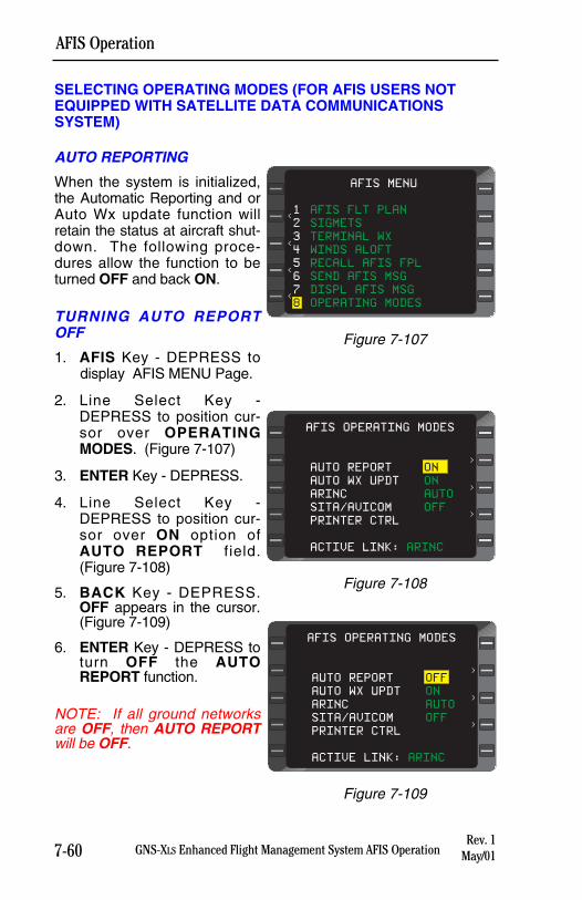
7-60 GNS-XLS Enhanced Flight Management System AFIS Operation
AFIS Operation
Rev. 1May/01
SELECTING OPERATING MODES (FOR AFIS USERS NOTEQUIPPED WITH SATELLITE DATA COMMUNICATIONSSYSTEM)
AUTO REPORTING
When the system is initialized,the Automatic Reporting and orAuto Wx update function willretain the status at aircraft shut-down. The following proce-dures allow the function to beturned OFF and back ON.
TURNING AUTO REPORTOFF
1. AFIS Key - DEPRESS todisplay AFIS MENU Page.
2. Line Select Key -DEPRESS to position cur-sor over OPERATINGMODES. (Figure 7-107)
3. ENTER Key - DEPRESS.
4. Line Select Key -DEPRESS to position cur-sor over ON option ofAUTO REPORT field.(Figure 7-108)
5. BACK Key - DEPRESS.OFF appears in the cursor.(Figure 7-109)
6. ENTER Key - DEPRESS toturn OFF the AUTOREPORT function.
NOTE: If all ground networksare OFF, then AUTO REPORTwill be OFF.
AFIS MENU
<
<
<
<
1 AFIS FLT PLAN
2 SIGMETS
3 TERMINAL WX
4 WINDS ALOFT
5 RECALL AFIS FPL
6 SEND AFIS MSG
7 DISPL AFIS MSG
8 OPERATING MODES
Figure 7-107
AFIS OPERATING MODES
>
>
>
AUTO REPORT ON
AUTO WX UPDT ON
ARINC AUTO
SITA/AVICOM OFF
PRINTER CTRL
ACTIVE LINK: ARINC
Figure 7-108
AFIS OPERATING MODES
>
>
>
AUTO REPORT OFF
AUTO WX UPDT ON
ARINC AUTO
SITA/AVICOM OFF
PRINTER CTRL
ACTIVE LINK: ARINC
Figure 7-109
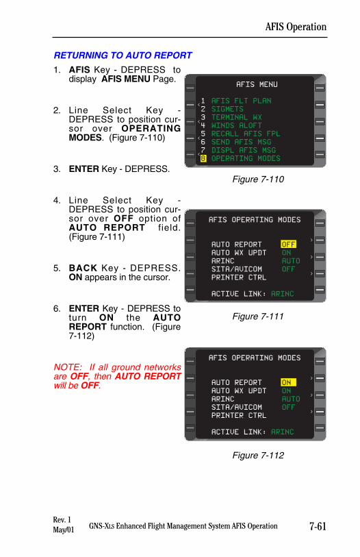
7-61GNS-XLS Enhanced Flight Management System AFIS Operation
AFIS Operation
Rev. 1May/01
RETURNING TO AUTO REPORT
1. AFIS Key - DEPRESS todisplay AFIS MENU Page.
2. Line Select Key -DEPRESS to position cur-sor over OPERATINGMODES. (Figure 7-110)
3. ENTER Key - DEPRESS.
4. Line Select Key -DEPRESS to position cur-sor over OFF option ofAUTO REPORT field.(Figure 7-111)
5. BACK Key - DEPRESS.ON appears in the cursor.
6. ENTER Key - DEPRESS toturn ON the AUTOREPORT function. (Figure7-112)
NOTE: If all ground networksare OFF, then AUTO REPORTwill be OFF.
AFIS MENU
<
<
<
<
1 AFIS FLT PLAN
2 SIGMETS
3 TERMINAL WX
4 WINDS ALOFT
5 RECALL AFIS FPL
6 SEND AFIS MSG
7 DISPL AFIS MSG
8 OPERATING MODES
Figure 7-110
AFIS OPERATING MODES
>
>
>
AUTO REPORT OFF
AUTO WX UPDT ON
ARINC AUTO
SITA/AVICOM OFF
PRINTER CTRL
ACTIVE LINK: ARINC
Figure 7-111
AFIS OPERATING MODES
>
>
>
AUTO REPORT ON
AUTO WX UPDT ON
ARINC AUTO
SITA/AVICOM OFF
PRINTER CTRL
ACTIVE LINK: ARINC
Figure 7-112
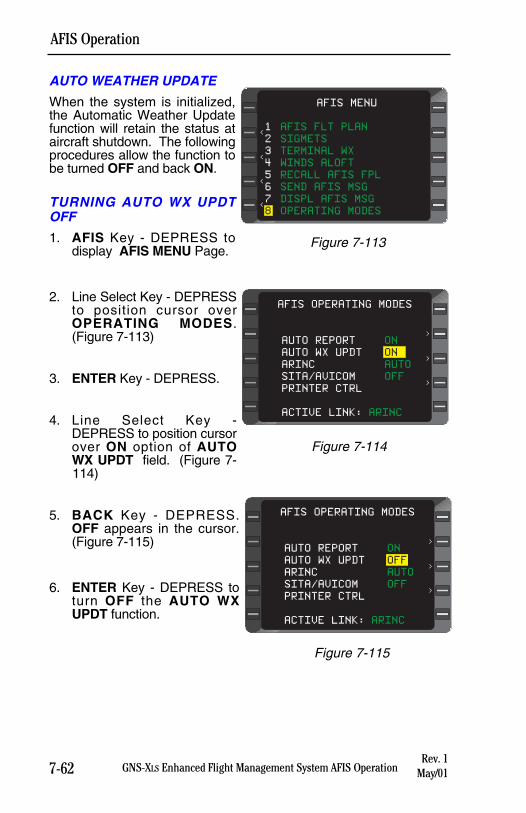
7-62 GNS-XLS Enhanced Flight Management System AFIS Operation
AFIS Operation
Rev. 1May/01
AUTO WEATHER UPDATE
When the system is initialized,the Automatic Weather Updatefunction will retain the status ataircraft shutdown. The followingprocedures allow the function tobe turned OFF and back ON.
TURNING AUTO WX UPDTOFF
1. AFIS Key - DEPRESS todisplay AFIS MENU Page.
2. Line Select Key - DEPRESSto position cursor overOPERATING MODES.(Figure 7-113)
3. ENTER Key - DEPRESS.
4. Line Select Key -DEPRESS to position cursorover ON option of AUTOWX UPDT field. (Figure 7-114)
5. BACK Key - DEPRESS.OFF appears in the cursor.(Figure 7-115)
6. ENTER Key - DEPRESS toturn OFF the AUTO WXUPDT function.
AFIS OPERATING MODES
>
>
>
AUTO REPORT ON
AUTO WX UPDT ON
ARINC AUTO
SITA/AVICOM OFF
PRINTER CTRL
ACTIVE LINK: ARINC
Figure 7-114
AFIS MENU
<
<
<
<
1 AFIS FLT PLAN
2 SIGMETS
3 TERMINAL WX
4 WINDS ALOFT
5 RECALL AFIS FPL
6 SEND AFIS MSG
7 DISPL AFIS MSG
8 OPERATING MODES
Figure 7-113
AFIS OPERATING MODES
>
>
>
AUTO REPORT ON
AUTO WX UPDT OFF
ARINC AUTO
SITA/AVICOM OFF
PRINTER CTRL
ACTIVE LINK: ARINC
Figure 7-115
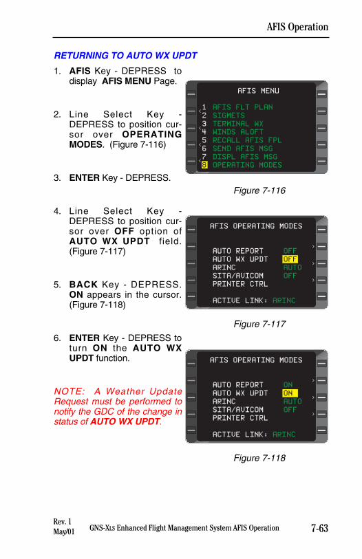
7-63GNS-XLS Enhanced Flight Management System AFIS Operation
AFIS Operation
Rev. 1May/01
RETURNING TO AUTO WX UPDT
1. AFIS Key - DEPRESS todisplay AFIS MENU Page.
2. Line Select Key -DEPRESS to position cur-sor over OPERATINGMODES. (Figure 7-116)
3. ENTER Key - DEPRESS.
4. Line Select Key -DEPRESS to position cur-sor over OFF option ofAUTO WX UPDT field.(Figure 7-117)
5. BACK Key - DEPRESS.ON appears in the cursor.(Figure 7-118)
6. ENTER Key - DEPRESS toturn ON the AUTO WXUPDT function.
NOTE: A Weather UpdateRequest must be performed tonotify the GDC of the change instatus of AUTO WX UPDT.
AFIS MENU
<
<
<
<
1 AFIS FLT PLAN
2 SIGMETS
3 TERMINAL WX
4 WINDS ALOFT
5 RECALL AFIS FPL
6 SEND AFIS MSG
7 DISPL AFIS MSG
8 OPERATING MODES
Figure 7-116
AFIS OPERATING MODES
>
>
>
AUTO REPORT OFF
AUTO WX UPDT OFF
ARINC AUTO
SITA/AVICOM OFF
PRINTER CTRL
ACTIVE LINK: ARINC
Figure 7-117
AFIS OPERATING MODES
>
>
>
AUTO REPORT ON
AUTO WX UPDT ON
ARINC AUTO
SITA/AVICOM OFF
PRINTER CTRL
ACTIVE LINK: ARINC
Figure 7-118
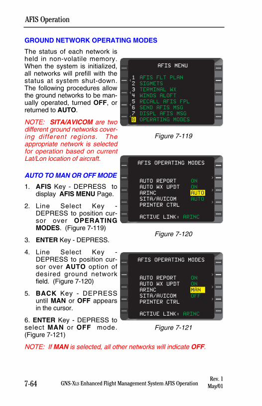
GROUND NETWORK OPERATING MODES
The status of each network isheld in non-volatile memory.When the system is initialized,all networks will prefill with thestatus at system shut-down.The following procedures allowthe ground networks to be man-ually operated, turned OFF, orreturned to AUTO.
NOTE: SITA/AVICOM are twodifferent ground networks cover-ing different regions. Theappropriate network is selectedfor operation based on currentLat/Lon location of aircraft.
AUTO TO MAN OR OFF MODE
1. AFIS Key - DEPRESS todisplay AFIS MENU Page.
2. Line Select Key -DEPRESS to position cur-sor over OPERATINGMODES. (Figure 7-119)
3. ENTER Key - DEPRESS.
4. Line Select Key -DEPRESS to position cur-sor over AUTO option ofdesired ground networkfield. (Figure 7-120)
5. BACK Key - DEPRESSuntil MAN or OFF appearsin the cursor.
6. ENTER Key - DEPRESS toselect MAN or OFF mode.(Figure 7-121)
NOTE: If MAN is selected, all other networks will indicate OFF.
7-64 GNS-XLS Enhanced Flight Management System AFIS Operation
AFIS Operation
Rev. 1May/01
AFIS OPERATING MODES
>
>
>
AUTO REPORT ON
AUTO WX UPDT ON
ARINC MAN
SITA/AVICOM OFF
PRINTER CTRL
ACTIVE LINK: ARINC
Figure 7-121
AFIS MENU
<
<
<
<
1 AFIS FLT PLAN
2 SIGMETS
3 TERMINAL WX
4 WINDS ALOFT
5 RECALL AFIS FPL
6 SEND AFIS MSG
7 DISPL AFIS MSG
8 OPERATING MODES
Figure 7-119
AFIS OPERATING MODES
>
>
>
AUTO REPORT ON
AUTO WX UPDT ON
ARINC AUTO
SITA/AVICOM AUTO
PRINTER CTRL
ACTIVE LINK: ARINC
Figure 7-120
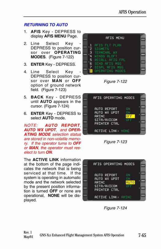
7-65GNS-XLS Enhanced Flight Management System AFIS Operation
AFIS Operation
Rev. 1May/01
RETURNING TO AUTO
1. AFIS Key - DEPRESS todisplay AFIS MENU Page.
2. Line Select Key -DEPRESS to position cur-sor over OPERATINGMODES. (Figure 7-122)
3. ENTER Key - DEPRESS.
4. Line Select Key -DEPRESS to position cur-sor over MAN or OFFoption of ground networkfield. (Figure 7-123)
5. BACK Key - DEPRESSuntil AUTO appears in thecursor. (Figure 7-124)
6. ENTER Key - DEPRESS toselect AUTO mode.
NOTE: AUTO REPORT,AUTO WX UPDT, and OPER-ATING MODE selection statusare stored in non-volatile memo-ry. If the operator turns to OFFor MAN, the operator must res-elect to turn ON.
The ACTIVE LINK informationat the bottom of the page indi-cates the network that is beingserviced at that time. If thesystem is operating in automaticmode and the network selectedby the present position informa-tion is turned OFF or none areoperational, NONE will be dis-played.
AFIS OPERATING MODES
>
>
>
AUTO REPORT ON
AUTO WX UPDT ON
ARINC OFF
SITA/AVICOM OFF
PRINTER CTRL
ACTIVE LINK: NONE
Figure 7-123
AFIS MENU
<
<
<
<
1 AFIS FLT PLAN
2 SIGMETS
3 TERMINAL WX
4 WINDS ALOFT
5 RECALL AFIS FPL
6 SEND AFIS MSG
7 DISPL AFIS MSG
8 OPERATING MODES
Figure 7-122
AFIS OPERATING MODES
>
>
>
AUTO REPORT ON
AUTO WX UPDT ON
ARINC AUTO
SITA/AVICOM OFF
PRINTER CTRL
ACTIVE LINK: ARINC
Figure 7-124
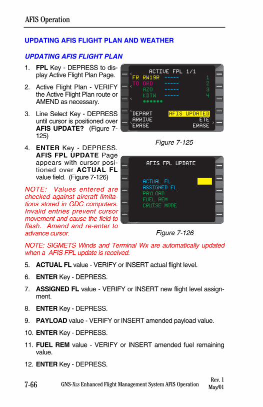
7-66 GNS-XLS Enhanced Flight Management System AFIS OperationRev. 1
May/01
AFIS Operation
UPDATING AFIS FLIGHT PLAN AND WEATHER
UPDATING AFIS FLIGHT PLAN
1. FPL Key - DEPRESS to dis-play Active Flight Plan Page.
2. Active Flight Plan - VERIFYthe Active Flight Plan route orAMEND as necessary.
3. Line Select Key - DEPRESSuntil cursor is positioned overAFIS UPDATE? (Figure 7-125)
4. ENTER Key - DEPRESS.AFIS FPL UPDATE Pageappears with cursor posi-tioned over ACTUAL FLvalue field. (Figure 7-126)
NOTE: Values entered arechecked against aircraft limita-tions stored in GDC computers.Invalid entries prevent cursormovement and cause the field toflash. Amend and re-enter toadvance cursor.
NOTE: SIGMETS Winds and Terminal Wx are automatically updatedwhen a AFIS FPL update is received.
5. ACTUAL FL value - VERIFY or INSERT actual flight level.
6. ENTER Key - DEPRESS.
7. ASSIGNED FL value - VERIFY or INSERT new flight level assign-ment.
8. ENTER Key - DEPRESS.
9. PAYLOAD value - VERIFY or INSERT amended payload value.
10. ENTER Key - DEPRESS.
11. FUEL REM value - VERIFY or INSERT amended fuel remainingvalue.
12. ENTER Key - DEPRESS.
ACTIVE FPL 1/1
FR RW19R ----- 1
TO ORD ----- 2
AZO ----- 3
KDTW ----- 4
******
DEPART AFIS UPDATED
ARRIVE ETE
ERASE ERASE
<
<
<
<
<
>
Figure 7-125
ACTUAL FL
ASSIGNED FL
PAYLOAD
FUEL REM
CRUISE MODE
AFIS FPL UPDATE
Figure 7-126
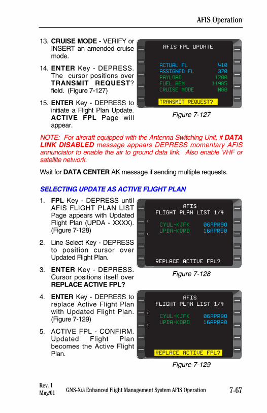
7-67GNS-XLS Enhanced Flight Management System AFIS OperationRev. 1May/01
AFIS Operation
13. CRUISE MODE - VERIFY orINSERT an amended cruisemode.
14. ENTER Key - DEPRESS.The cursor positions overTRANSMIT REQUEST?field. (Figure 7-127)
15. ENTER Key - DEPRESS toinitiate a Flight Plan Update.ACTIVE FPL Page willappear.
NOTE: For aircraft equipped with the Antenna Switching Unit, if DATALINK DISABLED message appears DEPRESS momentary AFISannunciator to enable the air to ground data link. Also enable VHF orsatellite network.
Wait for DATA CENTER AK message if sending multiple requests.
SELECTING UPDATE AS ACTIVE FLIGHT PLAN
1. FPL Key - DEPRESS untilAFIS FLIGHT PLAN LISTPage appears with UpdatedFlight Plan (UPDA - XXXX).(Figure 7-128)
2. Line Select Key - DEPRESSto position cursor overUpdated Flight Plan.
3. ENTER Key - DEPRESS.Cursor positions itself overREPLACE ACTIVE FPL?
4. ENTER Key - DEPRESS toreplace Active Flight Planwith Updated Flight Plan.(Figure 7-129)
5. ACTIVE FPL - CONFIRM.Updated Flight Planbecomes the Active FlightPlan.
ACTUAL FL 410
ASSIGNED FL 370
PAYLOAD 1200
FUEL REM 11985
CRUISE MODE M80
TRANSMIT REQUEST?
AFIS FPL UPDATE
Figure 7-127
FLIGHT PLAN LIST 1/4
CYUL-KJFK 06APR9O
UPDA-KORD 16APR90
REPLACE ACTIVE FPL?
AFIS
<
<
Figure 7-128
AFIS
<
<
FLIGHT PLAN LIST 1/4
CYUL-KJFK 06APR9O
UPDA-KORD 16APR90
REPLACE ACTIVE FPL?
Figure 7-129
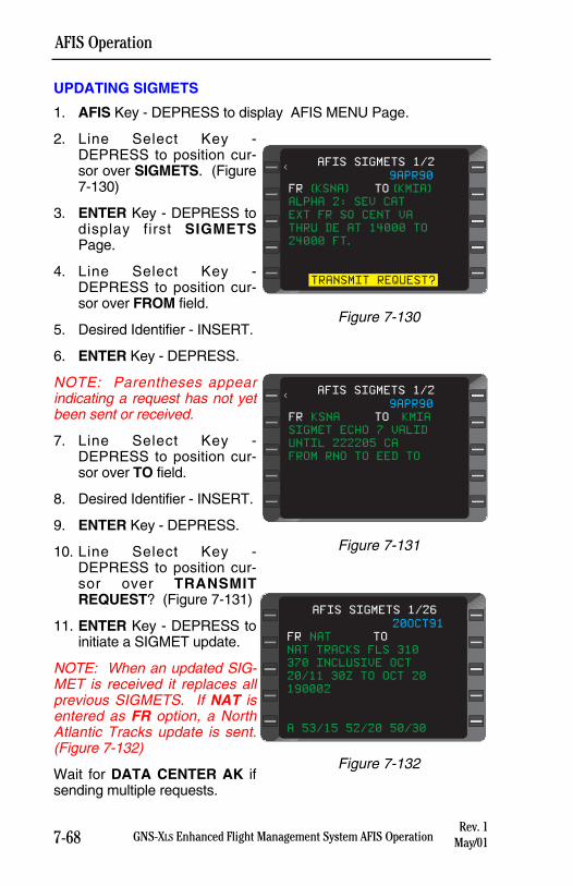
7-68 GNS-XLS Enhanced Flight Management System AFIS OperationRev. 1
May/01
AFIS Operation
UPDATING SIGMETS
1. AFIS Key - DEPRESS to display AFIS MENU Page.
2. Line Select Key -DEPRESS to position cur-sor over SIGMETS. (Figure7-130)
3. ENTER Key - DEPRESS todisplay first SIGMETSPage.
4. Line Select Key -DEPRESS to position cur-sor over FROM field.
5. Desired Identifier - INSERT.
6. ENTER Key - DEPRESS.
NOTE: Parentheses appearindicating a request has not yetbeen sent or received.
7. Line Select Key -DEPRESS to position cur-sor over TO field.
8. Desired Identifier - INSERT.
9. ENTER Key - DEPRESS.
10. Line Select Key -DEPRESS to position cur-sor over TRANSMITREQUEST? (Figure 7-131)
11. ENTER Key - DEPRESS toinitiate a SIGMET update.
NOTE: When an updated SIG-MET is received it replaces allprevious SIGMETS. If NAT isentered as FR option, a NorthAtlantic Tracks update is sent.(Figure 7-132)
Wait for DATA CENTER AK ifsending multiple requests.
AFIS SIGMETS 1/2
9APR90
FR (KSNA) TO (KMIA)
ALPHA 2: SEV CAT
EXT FR SO CENT VA
THRU DE AT 14000 TO
24000 FT.
TRANSMIT REQUEST?
<
Figure 7-130
AFIS SIGMETS 1/2
9APR90
FR KSNA TO KMIA
SIGMET ECHO 7 VALID
UNTIL 222205 CA
FROM RNO TO EED TO
<
Figure 7-131
20OCT91
FR NAT TO
NAT TRACKS FLS 310
370 INCLUSIVE OCT
20/11 30Z TO OCT 20
190002
A 53/15 52/20 50/30
AFIS SIGMETS 1/26
Figure 7-132
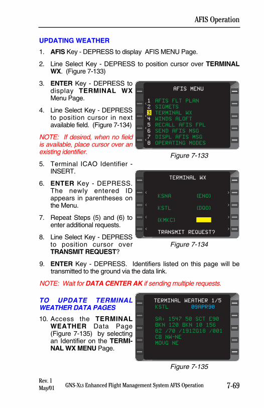
7-69GNS-XLS Enhanced Flight Management System AFIS OperationRev. 1May/01
AFIS Operation
UPDATING WEATHER
1. AFIS Key - DEPRESS to display AFIS MENU Page.
2. Line Select Key - DEPRESS to position cursor over TERMINALWX. (Figure 7-133)
3. ENTER Key - DEPRESS todisplay TERMINAL WXMenu Page.
4. Line Select Key - DEPRESSto position cursor in nextavailable field. (Figure 7-134)
NOTE: If desired, when no fieldis available, place cursor over anexisting identifier.
5. Terminal ICAO Identifier -INSERT.
6. ENTER Key - DEPRESS.The newly entered IDappears in parentheses onthe Menu.
7. Repeat Steps (5) and (6) toenter additional requests.
8. Line Select Key - DEPRESSto position cursor overTRANSMIT REQUEST?
9. ENTER Key - DEPRESS. Identifiers listed on this page will betransmitted to the ground via the data link.
NOTE: Wait for DATA CENTER AK if sending multiple requests.
TO UPDATE TERMINALWEATHER DATA PAGES
10. Access the TERMINALWEATHER Data Page(Figure 7-135) by selectingan Identifier on the TERMI-NAL WX MENU Page.
AFIS MENU
<
<
<
<
1 AFIS FLT PLAN
2 SIGMETS
3 TERMINAL WX
4 WINDS ALOFT
5 RECALL AFIS FPL
6 SEND AFIS MSG
7 DISPL AFIS MSG
8 OPERATING MODES
Figure 7-133
KSNA (ENO)
KSTL (DQO)
(KMKC)
TRANSMIT REQUEST?
TERMINAL WX
<
<
<
<
>
>
>
>
Figure 7-134
KSTL 09APR90
SA: 1547 50 SCT E90
BKN 120 BKN 10 156
82 /70 /1912G18 /001
CB NW-NE
MOVG NE
TERMINAL WEATHER 1/5
Figure 7-135
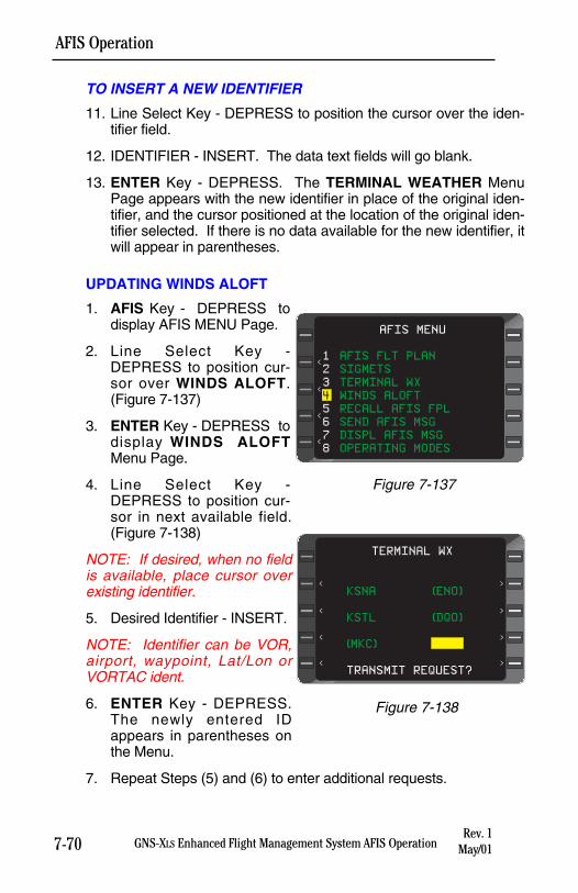
7-70 GNS-XLS Enhanced Flight Management System AFIS OperationRev. 1
May/01
AFIS Operation
TO INSERT A NEW IDENTIFIER
11. Line Select Key - DEPRESS to position the cursor over the iden-tifier field.
12. IDENTIFIER - INSERT. The data text fields will go blank.
13. ENTER Key - DEPRESS. The TERMINAL WEATHER MenuPage appears with the new identifier in place of the original iden-tifier, and the cursor positioned at the location of the original iden-tifier selected. If there is no data available for the new identifier, itwill appear in parentheses.
UPDATING WINDS ALOFT
1. AFIS Key - DEPRESS todisplay AFIS MENU Page.
2. Line Select Key -DEPRESS to position cur-sor over WINDS ALOFT.(Figure 7-137)
3. ENTER Key - DEPRESS todisplay WINDS ALOFTMenu Page.
4. Line Select Key -DEPRESS to position cur-sor in next available field.(Figure 7-138)
NOTE: If desired, when no fieldis available, place cursor overexisting identifier.
5. Desired Identifier - INSERT.
NOTE: Identifier can be VOR,airport, waypoint, Lat/Lon orVORTAC ident.
6. ENTER Key - DEPRESS.The newly entered IDappears in parentheses onthe Menu.
7. Repeat Steps (5) and (6) to enter additional requests.
AFIS MENU
<
<
<
<
1 AFIS FLT PLAN
2 SIGMETS
3 TERMINAL WX
4 WINDS ALOFT
5 RECALL AFIS FPL
6 SEND AFIS MSG
7 DISPL AFIS MSG
8 OPERATING MODES
Figure 7-137
KSNA (ENO)
KSTL (DQO)
(MKC)
TRANSMIT REQUEST?
TERMINAL WX
<
<
<
<
>
>
>
>
Figure 7-138
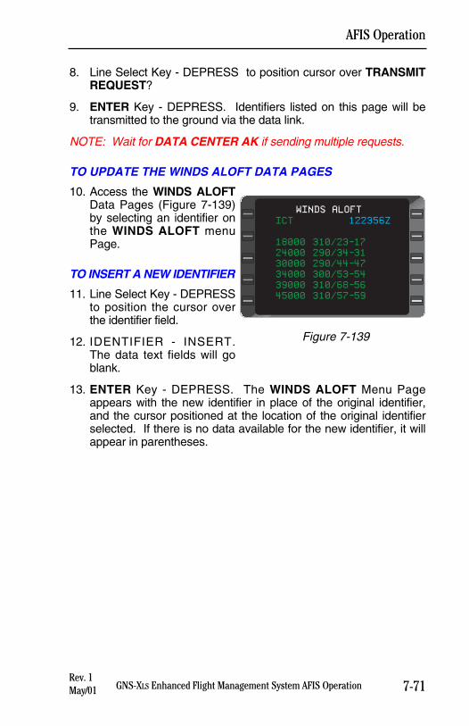
7-71GNS-XLS Enhanced Flight Management System AFIS OperationRev. 1May/01
AFIS Operation
8. Line Select Key - DEPRESS to position cursor over TRANSMITREQUEST?
9. ENTER Key - DEPRESS. Identifiers listed on this page will betransmitted to the ground via the data link.
NOTE: Wait for DATA CENTER AK if sending multiple requests.
TO UPDATE THE WINDS ALOFT DATA PAGES
10. Access the WINDS ALOFTData Pages (Figure 7-139)by selecting an identifier onthe WINDS ALOFT menuPage.
TO INSERT A NEW IDENTIFIER
11. Line Select Key - DEPRESSto position the cursor overthe identifier field.
12. IDENTIFIER - INSERT.The data text fields will goblank.
13. ENTER Key - DEPRESS. The WINDS ALOFT Menu Pageappears with the new identifier in place of the original identifier,and the cursor positioned at the location of the original identifierselected. If there is no data available for the new identifier, it willappear in parentheses.
ICT 122356Z
18000 310/23-17
24000 290/34-31
30000 290/44-47
34000 300/53-54
39000 310/68-56
45000 310/57-59
WINDS ALOFT
Figure 7-139
AFIS GRAPHICAL WEATHER OPERATIONSThe AFIS functions described in this section are available only on anAFIS Data Management Unit (DMU) equipped to process graphicalweather. If your AFIS DMU has not been equipped to process graphi-cal weather the WX Graphics option will not be listed on the AFISMain Menu. Contact your nearest Honeywell dealer or the GlobalData Center for AFIS DMU upgrade information.
INTRODUCTION
AFIS provides timely aviation oriented graphical weather products,which supplement the variety of AFIS textual weather. Like otherAFIS messages, Weather Graphics are transmitted via VHF or satel-lite data transceivers. In order to provide an additional level of situa-tional awareness, own-ship position and flight plan are overlaid onthe graphical weather products. The GNS-XLS and AFIS DMU mustbe configured to receive and display Weather AFIS GraphicalWeather. AFIS Graphical Weather hardware also includes a separateRemote Processing Unit (RPU) and installation kit. The RPU usesan updateable PCMCIA Data Card, which contains the applicationsoftware, base maps, and an aeronautical database. The Data Cardmust remain in the RPU during use. Ask your Honeywell dealer forsubscription information to ensure your unit is using the most currentRPU software.
An optional SRAM PCMCIA card is available for storage of uplinkedweather products during power interrupts. Uplinked AFIS GraphicalWeather products that are older than 6 hours will delete automaticallyto prevent unintended use. It is possible to display AFIS GraphicalWeather on up to two GNS-XLS units with a single AFIS DMU, how-ever each FMS must be configured with a separate RPU. Contactyour Honeywell dealer for details on dual RPU installations.
Available Graphical Information Includes:
Moving map with special use airspace, geographic reference infor-mation display.
Airport and FBO directory information.
NEXRAD weather with historical replay and convective 1 hour fore-cast information.
CATMET/METAR weather.
Winds Aloft.
Significant Weather.
7-73GNS-XLS Enhanced Flight Management System AFIS Operation
AFIS Operation
Rev. 1May/01
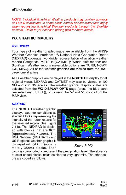
NOTE: Individual Graphical Weather products may contain upwardsof 11,000 characters. In some areas normal per character fees applywhen requesting Graphical Weather products through the Satellitenetwork. Refer to your chosen pricing plan for more details.
WX GRAPHIC IMAGERY
OVERVIEW
Four types of weather graphic maps are available from the AFIS®Weather Graphics interface: US National Next Generation Radar(NEXRAD) coverage; worldwide representation of aviation weatherreports Categorical METARs (CATMET); Winds aloft reports; andSignificant Weather reports (selectable options are TURB, NCWF,ICE, MISC). All of the weather graphics are viewed from the MAPpage, one at a time.
AFIS weather graphics are displayed in the NORTH UP display for allregional views. NEXRAD and CATMET may also be viewed in 100NM and 200 NM scales. The weather graphic display scales areselected from the WX DISPLAY OPTS page (press the blue caretline select key (LSK 3L)), or by using the “+” and “-“ options from theMAP view.
NEXRAD
The NEXRAD weather graphicdisplays weather conditions asshaded blocks representing theintensity of the radar returns forthe selected region. See Figure7-140. The NEXRAD is depict-ed with blocks that are 8km2
(approximately 4.3nm). TheUSA National (USANATL) andUS Regional weather graphic isdisplayed with 64 km2 (approxi-mately 35nm) blocks. Eachblock is color-coded to represent the precipitation level. The absenceof color-coded blocks indicates clear to very light mist. The other col-ors are coded as follows:
7-74 GNS-XLS Enhanced Flight Management System AFIS Operation
AFIS Operation
Rev. 1May/01
Figure 7-140
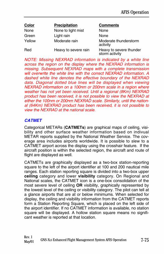
Color Precipitation CommentsNone None to light mist NoneGreen Light rain NoneYellow Moderate rain Moderate thunderstorm
activityRed Heavy to severe rain Heavy to severe thunder
storm activity
NOTE: Missing NEXRAD information is indicated by a white lineacross the region on the display where the NEXRAD information ismissing. Subsequent NEXRAD maps with a complete transmissionwill overwrite the white line with the correct NEXRAD information. Adashed white line denotes the effective boundary of the NEXRADdata. Diagonal dotted blue lines will be displayed when viewingNEXRAD information on a 100nm or 200nm scale in a region whereweather has not yet been received. Until a regional (8Km) NEXRADproduct has been received, it is not possible to view the NEXRAD ateither the 100nm or 200nm NEXRAD scale. Similarly, until the nation-al (64Km) NEXRAD product has been received, it is not possible toview the NEXRAD at the national scale.
CATMET
Categorical METARs (CATMETs) are graphical maps of ceiling, visi-bility and other surface weather information based on indivualMETAR reports supplied by the National Weather Service. The cov-erage area includes airports worldwide. It is possible to slew to aCATMET airport across the display using the crosshair feature. If theaircraft position is within the selected region, the aircraft and route offlight are displayed as well.
CATMETs are graphically displayed as a two-box station-reportingsquare to the left of the airport identifier at 100 and 200 nautical mileranges. Each station reporting square is divided into a two-box upperceiling category and lower visibility category. On Regional andNational scales, the CATMET icon is a one-box consolidation of themost severe level of ceiling OR visibility, graphically represented bythe lowest level of the ceiling or visibility category. The pilot can tell ata glance airports that are at or below minimums. When selected fordisplay, the ceiling and visibility information from the CATMET reportsform a Station Reporting Square, which is placed on the left side ofthe airport identifier. If no CATMET information is available, no stationsquare will be displayed. A hollow station square means no signifi-cant weather is reported at that location.
7-75GNS-XLS Enhanced Flight Management System AFIS Operation
AFIS Operation
Rev. 1May/01
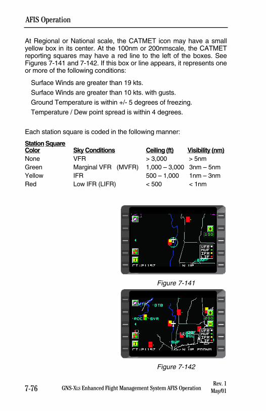
7-76 GNS-XLS Enhanced Flight Management System AFIS Operation
AFIS Operation
At Regional or National scale, the CATMET icon may have a smallyellow box in its center. At the 100nm or 200nmscale, the CATMETreporting squares may have a red line to the left of the boxes. SeeFigures 7-141 and 7-142. If this box or line appears, it represents oneor more of the following conditions:
Surface Winds are greater than 19 kts.
Surface Winds are greater than 10 kts. with gusts.
Ground Temperature is within +/- 5 degrees of freezing.
Temperature / Dew point spread is within 4 degrees.
Each station square is coded in the following manner:
Station SquareColor Sky Conditions Ceiling (ft) Visibility (nm)None VFR > 3,000 > 5nmGreen Marginal VFR (MVFR) 1,000 – 3,000 3nm – 5nmYellow IFR 500 – 1,000 1nm – 3nmRed Low IFR (LIFR) < 500 < 1nm
Rev. 1May/01
Figure 7-141
Figure 7-142
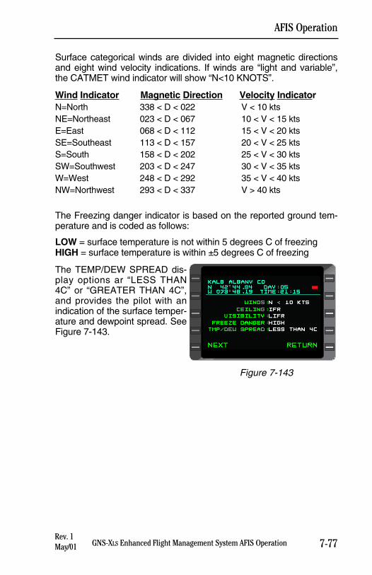
Surface categorical winds are divided into eight magnetic directionsand eight wind velocity indications. If winds are “light and variable”,the CATMET wind indicator will show “N<10 KNOTS”.
Wind Indicator Magnetic Direction Velocity IndicatorN=North 338 < D < 022 V < 10 ktsNE=Northeast 023 < D < 067 10 < V < 15 ktsE=East 068 < D < 112 15 < V < 20 ktsSE=Southeast 113 < D < 157 20 < V < 25 ktsS=South 158 < D < 202 25 < V < 30 ktsSW=Southwest 203 < D < 247 30 < V < 35 ktsW=West 248 < D < 292 35 < V < 40 ktsNW=Northwest 293 < D < 337 V > 40 kts
The Freezing danger indicator is based on the reported ground tem-perature and is coded as follows:
LOW = surface temperature is not within 5 degrees C of freezingHIGH = surface temperature is within ±5 degrees C of freezing
The TEMP/DEW SPREAD dis-play options ar “LESS THAN4C” or “GREATER THAN 4C”,and provides the pilot with anindication of the surface temper-ature and dewpoint spread. SeeFigure 7-143.
7-77GNS-XLS Enhanced Flight Management System AFIS Operation
AFIS Operation
Rev. 1May/01
Figure 7-143
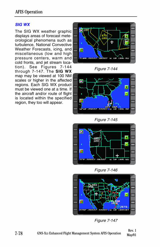
7-78 GNS-XLS Enhanced Flight Management System AFIS Operation
AFIS Operation
SIG WX
The SIG WX weather graphicdisplays areas of forecast mete-orological phenomena such asturbulence, National ConvectiveWeather Forecasts, icing, andmiscellaneous (low and highpressure centers, warm andcold fronts, and jet stream loca-tion). See Figures 7-144through 7-147. The SIG WXmap may be viewed at 100 NMscales or higher in the affectedregions. Each SIG WX productmust be viewed one at a time. Ifthe aircraft and/or route of flightis located within the specifiedregion, they too will appear.
Rev. 1May/01
Figure 7-144
Figure 7-145
Figure 7-146
Figure 7-147
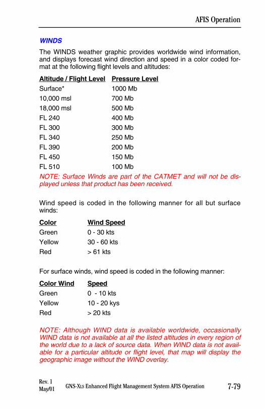
7-79GNS-XLS Enhanced Flight Management System AFIS Operation
AFIS Operation
WINDS
The WINDS weather graphic provides worldwide wind information,and displays forecast wind direction and speed in a color coded for-mat at the following flight levels and altitudes:
Altitude / Flight Level Pressure LevelSurface* 1000 Mb
10,000 msl 700 Mb
18,000 msl 500 Mb
FL 240 400 Mb
FL 300 300 Mb
FL 340 250 Mb
FL 390 200 Mb
FL 450 150 Mb
FL 510 100 Mb
NOTE: Surface Winds are part of the CATMET and will not be dis-played unless that product has been received.
Wind speed is coded in the following manner for all but surfacewinds:
Color Wind SpeedGreen 0 - 30 kts
Yellow 30 - 60 kts
Red > 61 kts
For surface winds, wind speed is coded in the following manner:
Color Wind SpeedGreen 0 - 10 kts
Yellow 10 - 20 kys
Red > 20 kts
NOTE: Although WIND data is available worldwide, occasionallyWIND data is not available at all the listed altitudes in every region ofthe world due to a lack of source data. When WIND data is not avail-able for a particular altitude or flight level, that map will display thegeographic image without the WIND overlay.
Rev. 1May/01
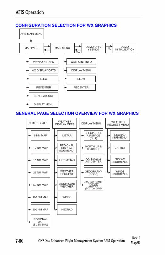
CONFIGURATION SELECTION FOR WX GRAPHICS
GENERAL PAGE SELECTION OVERVIEW FOR WX GRAPHICS
7-80 GNS-XLS Enhanced Flight Management System AFIS Operation
AFIS Operation
Rev. 1May/01
MAP PAGE
WAYPOINT INFO
MAIN MENU
AFIS MAIN MENU
DEMO OFF?YES/NO?
DEMOINITIALIZATION
YesNo
WX DISPLAY OPTS
SLEW
RECENTER
SCALE ADJUST
DISPLAY MENU
WAYPOINT INFO
DISPLAY MENU
SLEW
RECENTER
WEATHERREQUEST MENUDISPLAY MENU
WEATHERDISPLAY OPTSCHART SCALE
5 NM MAP
10 NM MAP
15 NM MAP
25 NM MAP
50 NM MAP
100 NM MAP
200 NM MAP
REGIONALMAP
(SUBMENU)
METAR
REGIONALDISPLAY
(SUBMENU)
LIST METAR
WEATHERREQUEST
SIGNIFICANTWEATHER
WINDS
NEXRAD
SPECIAL USEAIRSPACE
(SUA)
NORTH UP &TRACK UP
A/C EDGE &A/C CENTER
GEOGRAPHY(GEOG)
RPU SOFTWAREVERSIONNUMBER
(BOTTOM LINE)
NEXRAD(SUBMENU)
CATMET
SIG WX(SUBMENU)
WINDS(SUBMENU)
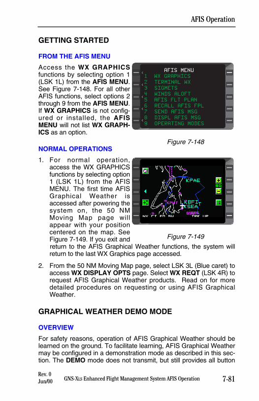
GETTING STARTED
FROM THE AFIS MENU
Access the WX GRAPHICSfunctions by selecting option 1(LSK 1L) from the AFIS MENU.See Figure 7-148. For all otherAFIS functions, select options 2through 9 from the AFIS MENU.If WX GRAPHICS is not config-ured or installed, the AFISMENU will not list WX GRAPH-ICS as an option.
NORMAL OPERATIONS
1. For normal operation,access the WX GRAPHICSfunctions by selecting option1 (LSK 1L) from the AFISMENU. The first time AFISGraphical Weather isaccessed after powering thesystem on, the 50 NMMoving Map page willappear with your positioncentered on the map. SeeFigure 7-149. If you exit andreturn to the AFIS Graphical Weather functions, the system willreturn to the last WX Graphics page accessed.
2. From the 50 NM Moving Map page, select LSK 3L (Blue caret) toaccess WX DISPLAY OPTS page. Select WX REQT (LSK 4R) torequest AFIS Graphical Weather products. Read on for moredetailed procedures on requesting or using AFIS GraphicalWeather.
GRAPHICAL WEATHER DEMO MODE
OVERVIEW
For safety reasons, operation of AFIS Graphical Weather should belearned on the ground. To facilitate learning, AFIS Graphical Weathermay be configured in a demonstration mode as described in this sec-tion. The DEMO mode does not transmit, but still provides all button
7-81GNS-XLS Enhanced Flight Management System AFIS OperationRev. 0Jun/00
AFIS Operation
Figure 7-149
AFIS MENU
1 WX GRAPHICS
2 TERMINAL WX
3 SIGMETS
4 WINDS ALOFT
5 AFIS FLT PLAN
6 RECALL AFIS FPL
7 SEND AFIS MSG
8 DISPL AFIS MSG
9 OPERATING MODES
<
<
<
<
<
Figure 7-148
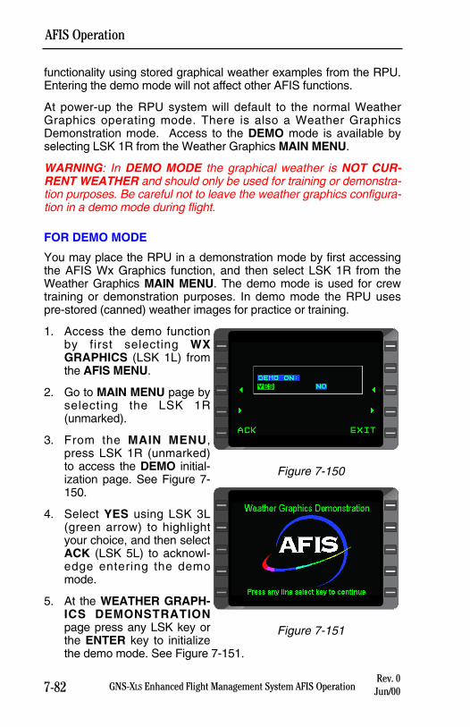
functionality using stored graphical weather examples from the RPU.Entering the demo mode will not affect other AFIS functions.
At power-up the RPU system will default to the normal WeatherGraphics operating mode. There is also a Weather GraphicsDemonstration mode. Access to the DEMO mode is available byselecting LSK 1R from the Weather Graphics MAIN MENU.
WARNING: In DEMO MODE the graphical weather is NOT CUR-RENT WEATHER and should only be used for training or demonstra-tion purposes. Be careful not to leave the weather graphics configura-tion in a demo mode during flight.
FOR DEMO MODE
You may place the RPU in a demonstration mode by first accessingthe AFIS Wx Graphics function, and then select LSK 1R from theWeather Graphics MAIN MENU. The demo mode is used for crewtraining or demonstration purposes. In demo mode the RPU usespre-stored (canned) weather images for practice or training.
1. Access the demo functionby first selecting WXGRAPHICS (LSK 1L) fromthe AFIS MENU.
2. Go to MAIN MENU page byselecting the LSK 1R(unmarked).
3. From the MAIN MENU,press LSK 1R (unmarked)to access the DEMO initial-ization page. See Figure 7-150.
4. Select YES using LSK 3L(green arrow) to highlightyour choice, and then selectACK (LSK 5L) to acknowl-edge entering the demomode.
5. At the WEATHER GRAPH-ICS DEMONSTRATIONpage press any LSK key orthe ENTER key to initializethe demo mode. See Figure 7-151.
7-82 GNS-XLS Enhanced Flight Management System AFIS OperationRev. 0
Jun/00
AFIS Operation
Figure 7-151
Figure 7-150
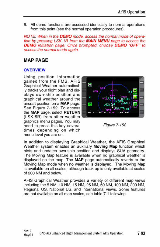
7-83GNS-XLS Enhanced Flight Management System AFIS Operation
AFIS Operation
6. All demo functions are accessed identically to normal operationsfrom this point (see the normal operation procedures).
NOTE: When in the DEMO mode, access the normal mode of opera-tion by pressing LSK 1R from the MAIN MENU page to access theDEMO initiation page. Once prompted, choose DEMO “OFF” toaccess the normal mode again.
MAP PAGE
OVERVIEW
Using position informationgained from the FMS, AFISGraphical Weather automatical-ly tracks your flight plan and dis-plays own-ship position andgraphical weather around theaircraft position on a MAP page.See Figure 7-152. To accessthe MAP page, select RETURN(LSK 5R) from other weathergraphics menu pages. You mayneed to press this key severaltimes depending on whichmenu level you are on.
In addition to displaying Graphical Weather, the AFIS GraphicalWeather system enables an auxiliary Moving Map function whichplots and updates own-ship position and displays SUA geometry.The Moving Map feature is available when no graphical weather isdisplayed on the map. The MAP page automatically reverts to theMoving Map mode when no weather is displayed. The Moving Mapis available on all scales, although track up is only available at scalesof 200 NM and below.
AFIS Graphical Weather provides a variety of different map viewsincluding the 5 NM, 10 NM, 15 NM, 25 NM, 50 NM, 100 NM, 200 NM,Regional US, National US, and International views. Some featuresare not available on all map scales, see table 7-1 following.
Rev. 1May/01
Figure 7-152
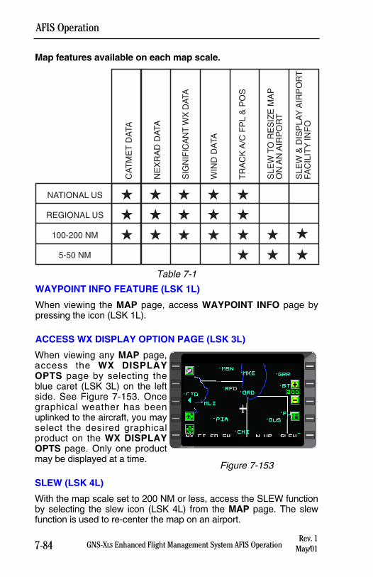
7-84 GNS-XLS Enhanced Flight Management System AFIS Operation
AFIS Operation
Map features available on each map scale.
WAYPOINT INFO FEATURE (LSK 1L)
When viewing the MAP page, access WAYPOINT INFO page bypressing the icon (LSK 1L).
ACCESS WX DISPLAY OPTION PAGE (LSK 3L)
When viewing any MAP page,access the WX DISPLAYOPTS page by selecting theblue caret (LSK 3L) on the leftside. See Figure 7-153. Oncegraphical weather has beenuplinked to the aircraft, you mayselect the desired graphicalproduct on the WX DISPLAYOPTS page. Only one productmay be displayed at a time.
SLEW (LSK 4L)
With the map scale set to 200 NM or less, access the SLEW functionby selecting the slew icon (LSK 4L) from the MAP page. The slewfunction is used to re-center the map on an airport.
Rev. 1May/01
Figure 7-153
Table 7-1
CA
TM
ET
DA
TA
NE
XR
AD
DA
TA
SIG
NIF
ICA
NT
WX
DAT
A
WIN
D D
ATA
TR
AC
K A
/C F
PL
& P
OS
SLE
W T
O R
ES
IZE
MA
PO
N A
N A
IRP
OR
T
SLE
W &
DIS
PLA
Y A
IRP
OR
TFA
CIL
ITY
INF
O
NATIONAL US
REGIONAL US
100-200 NM
5-50 NM
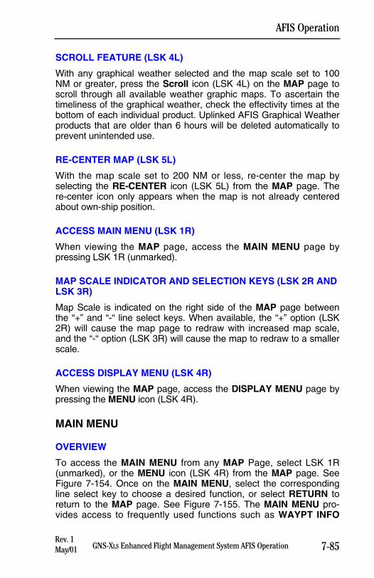
SCROLL FEATURE (LSK 4L)
With any graphical weather selected and the map scale set to 100NM or greater, press the Scroll icon (LSK 4L) on the MAP page toscroll through all available weather graphic maps. To ascertain thetimeliness of the graphical weather, check the effectivity times at thebottom of each individual product. Uplinked AFIS Graphical Weatherproducts that are older than 6 hours will be deleted automatically toprevent unintended use.
RE-CENTER MAP (LSK 5L)
With the map scale set to 200 NM or less, re-center the map byselecting the RE-CENTER icon (LSK 5L) from the MAP page. There-center icon only appears when the map is not already centeredabout own-ship position.
ACCESS MAIN MENU (LSK 1R)
When viewing the MAP page, access the MAIN MENU page bypressing LSK 1R (unmarked).
MAP SCALE INDICATOR AND SELECTION KEYS (LSK 2R ANDLSK 3R)
Map Scale is indicated on the right side of the MAP page betweenthe “+” and “-“ line select keys. When available, the “+” option (LSK2R) will cause the map page to redraw with increased map scale,and the “-“ option (LSK 3R) will cause the map to redraw to a smallerscale.
ACCESS DISPLAY MENU (LSK 4R)
When viewing the MAP page, access the DISPLAY MENU page bypressing the MENU icon (LSK 4R).
MAIN MENU
OVERVIEW
To access the MAIN MENU from any MAP Page, select LSK 1R(unmarked), or the MENU icon (LSK 4R) from the MAP page. SeeFigure 7-154. Once on the MAIN MENU, select the correspondingline select key to choose a desired function, or select RETURN toreturn to the MAP page. See Figure 7-155. The MAIN MENU pro-vides access to frequently used functions such as WAYPT INFO
7-85GNS-XLS Enhanced Flight Management System AFIS Operation
AFIS Operation
Rev. 1May/01
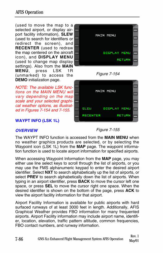
7-86 GNS-XLS Enhanced Flight Management System AFIS Operation
AFIS Operation
(used to move the map to aselected airport, or display air-port facility information), SLEW(used to search for identifiers orredirect the screen), andRECENTER (used to redrawthe map centered on the aircrafticon), and DISPLAY MENU(used to change map displaysettings). Also from the MAINMENU, press LSK 1R(unmarked) to access theDEMO initialization page.
NOTE: The available LSK func-tions on the MAIN MENU willvary depending on the mapscale and your selected graphi-cal weather options, as illustrat-ed in Figures 7-154 and 7-155.
WAYPT INFO (LSK 1L)
OVERVIEW
The WAYPT INFO function is accessed from the MAIN MENU whenno weather graphics products are selected, or by selecting theWaypoint icon (LSK 1L) from the MAP page. The waypoint informa-tion function is used to locate airport information for specified airports.
When accessing Waypoint Information from the MAP page, you mayeither use line select keys to scroll through the list of airports, or youmay use the FMS alphanumeric keypad to enter the desired airportidentifier. Select NXT to search alphabetically up the list of airports, orselect PREV to search alphabetically down the list of airports. Whentyping in an airport identifier, press BACK to move the cursor left onespace, or press SEL to move the cursor right one space. When thedesired identifier is shown on the bottom of the page, press ACK toview the airport facility information for that airport.
Airport Facility Information is available for public airports with hardsurfaced runways of at least 3000 feet in length. Additionally, AFISGraphical Weather provides FBO information for many frequentedairports. Airport Facility information may include airport name, identifi-er, location, elevation, traffic pattern altitude, common frequencies,FBO contact numbers, and runway information.
Rev. 1May/01
Figure 7-154
Figure 7-155
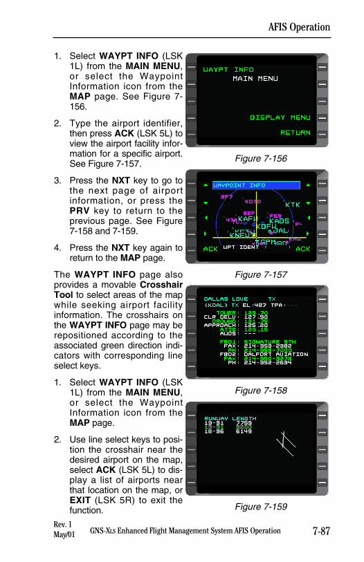
7-87GNS-XLS Enhanced Flight Management System AFIS Operation
AFIS Operation
1. Select WAYPT INFO (LSK1L) from the MAIN MENU,or select the WaypointInformation icon from theMAP page. See Figure 7-156.
2. Type the airport identifier,then press ACK (LSK 5L) toview the airport facility infor-mation for a specific airport.See Figure 7-157.
3. Press the NXT key to go tothe next page of airportinformation, or press thePRV key to return to theprevious page. See Figure7-158 and 7-159.
4. Press the NXT key again toreturn to the MAP page.
The WAYPT INFO page alsoprovides a movable CrosshairTool to select areas of the mapwhile seeking airport facilityinformation. The crosshairs onthe WAYPT INFO page may berepositioned according to theassociated green direction indi-cators with corresponding lineselect keys.
1. Select WAYPT INFO (LSK1L) from the MAIN MENU,or select the WaypointInformation icon from theMAP page.
2. Use line select keys to posi-tion the crosshair near thedesired airport on the map,select ACK (LSK 5L) to dis-play a list of airports nearthat location on the map, orEXIT (LSK 5R) to exit thefunction.
Rev. 1May/01
Figure 7-156
Figure 7-157
Figure 7-158
Figure 7-159
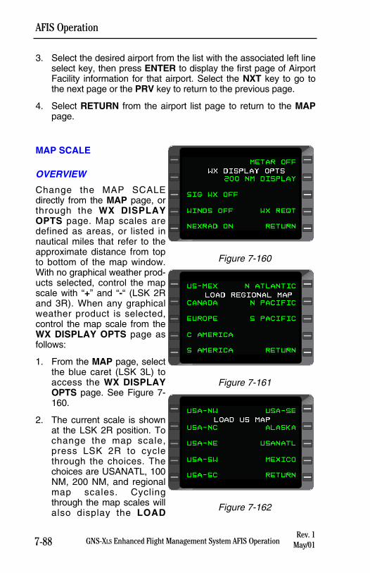
7-88 GNS-XLS Enhanced Flight Management System AFIS Operation
AFIS Operation
Rev. 1May/01
3. Select the desired airport from the list with the associated left lineselect key, then press ENTER to display the first page of AirportFacility information for that airport. Select the NXT key to go tothe next page or the PRV key to return to the previous page.
4. Select RETURN from the airport list page to return to the MAPpage.
MAP SCALE
OVERVIEW
Change the MAP SCALEdirectly from the MAP page, orthrough the WX DISPLAYOPTS page. Map scales aredefined as areas, or listed innautical miles that refer to theapproximate distance from topto bottom of the map window.With no graphical weather prod-ucts selected, control the mapscale with “+” and “-“ (LSK 2Rand 3R). When any graphicalweather product is selected,control the map scale from theWX DISPLAY OPTS page asfollows:
1. From the MAP page, selectthe blue caret (LSK 3L) toaccess the WX DISPLAYOPTS page. See Figure 7-160.
2. The current scale is shownat the LSK 2R position. Tochange the map scale,press LSK 2R to cyclethrough the choices. Thechoices are USANATL, 100NM, 200 NM, and regionalmap scales. Cyclingthrough the map scales willalso display the LOAD
Figure 7-160
Figure 7-161
Figure 7-162
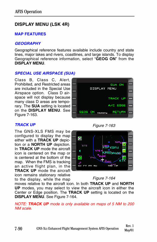
7-90 GNS-XLS Enhanced Flight Management System AFIS Operation
AFIS Operation
DISPLAY MENU (LSK 4R)
MAP FEATURES
GEOGRAPHY
Geographical reference features available include country and statelines, major lakes and rivers, coastlines, and large islands. To displayGeographical reference information, select “GEOG ON” from theDISPLAY MENU.
SPECIAL USE AIRSPACE (SUA)
Class B, Class C, Alert,Prohibited, and Restricted areasare included in the Special UseAirspace option. Class D air-space will not display becausemany class D areas are tempo-rary. The SUA setting is locatedon the DISPLAY MENU. SeeFigure 7-163.
TRACK UP
The GNS-XLS FMS may beconfigured to display the mapeither with a TRACK UP depic-tion or a NORTH UP depiction.In TRACK UP mode the aircrafticon is centered on the map oris centered at the bottom of themap. When the FMS is trackingan active flight plan, in theTRACK UP mode the aircrafticon remains stationary relativeto the display, while the mapmoves relative to the aircraft icon. In both TRACK UP and NORTHUP modes, you may select to view the aircraft icon in either theCenter or Edge position. The TRACK UP setting is located on theDISPLAY MENU. See Figure 7-164.
NOTE: TRACK UP mode is only available on maps of 5 NM to 200NM scale.
Rev. 1May/01
WAYPT INFO
MAIN MENU
SCALE
SLEW DISPLAY MENU
RECENTER RETURN
Figure 7-163
Figure 7-164
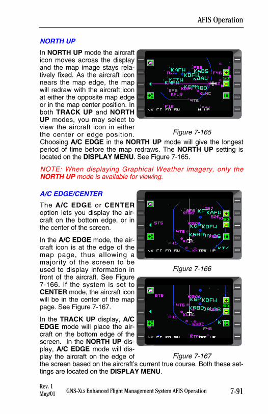
7-91GNS-XLS Enhanced Flight Management System AFIS Operation
AFIS Operation
NORTH UP
In NORTH UP mode the aircrafticon moves across the displayand the map image stays rela-tively fixed. As the aircraft iconnears the map edge, the mapwill redraw with the aircraft iconat either the opposite map edgeor in the map center position. Inboth TRACK UP and NORTHUP modes, you may select toview the aircraft icon in eitherthe center or edge position.Choosing A/C EDGE in the NORTH UP mode will give the longestperiod of time before the map redraws. The NORTH UP setting islocated on the DISPLAY MENU. See Figure 7-165.
NOTE: When displaying Graphical Weather imagery, only theNORTH UP mode is available for viewing.
A/C EDGE/CENTER
The A/C EDGE or CENTERoption lets you display the air-craft on the bottom edge, or inthe center of the screen.
In the A/C EDGE mode, the air-craft icon is at the edge of themap page, thus allowing amajority of the screen to beused to display information infront of the aircraft. See Figure7-166. If the system is set toCENTER mode, the aircraft iconwill be in the center of the mappage. See Figure 7-167.
In the TRACK UP display, A/CEDGE mode will place the air-craft on the bottom edge of thescreen. In the NORTH UP dis-play, A/C EDGE mode will dis-play the aircraft on the edge ofthe screen based on the aircraft’s current true course. Both these set-tings are located on the DISPLAY MENU.
Rev. 1May/01
Figure 7-165
Figure 7-166
Figure 7-167
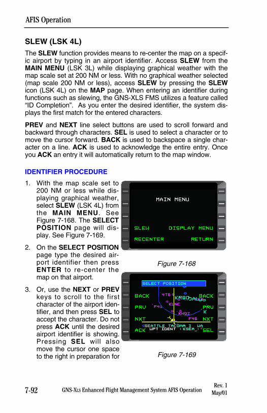
7-92 GNS-XLS Enhanced Flight Management System AFIS Operation
AFIS Operation
SLEW (LSK 4L)The SLEW function provides means to re-center the map on a specif-ic airport by typing in an airport identifier. Access SLEW from theMAIN MENU (LSK 3L) while displaying graphical weather with themap scale set at 200 NM or less. With no graphical weather selected(map scale 200 NM or less), access SLEW by pressing the SLEWicon (LSK 4L) on the MAP page. When entering an identifier duringfunctions such as slewing, the GNS-XLS FMS utilizes a feature called“ID Completion”. As you enter the desired identifier, the system dis-plays the first match for the entered characters.
PREV and NEXT line select buttons are used to scroll forward andbackward through characters. SEL is used to select a character or tomove the cursor forward. BACK is used to backspace a single char-acter on a line. ACK is used to acknowledge the entire entry. Onceyou ACK an entry it will automatically return to the map window.
IDENTIFIER PROCEDURE
1. With the map scale set to200 NM or less while dis-playing graphical weather,select SLEW (LSK 4L) fromthe MAIN MENU. SeeFigure 7-168. The SELECTPOSITION page will dis-play. See Figure 7-169.
2. On the SELECT POSITIONpage type the desired air-port identifier then pressENTER to re-center themap on that airport.
3. Or, use the NEXT or PREVkeys to scroll to the firstcharacter of the airport iden-tifier, and then press SEL toaccept the character. Do notpress ACK until the desiredairport identifier is showing.Pressing SEL will alsomove the cursor one spaceto the right in preparation for
Rev. 1May/01
Figure 7-168
Figure 7-169
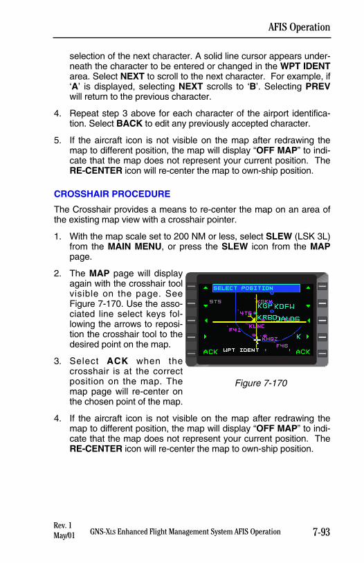
7-93GNS-XLS Enhanced Flight Management System AFIS Operation
AFIS Operation
selection of the next character. A solid line cursor appears under-neath the character to be entered or changed in the WPT IDENTarea. Select NEXT to scroll to the next character. For example, if‘A’ is displayed, selecting NEXT scrolls to ‘B’. Selecting PREVwill return to the previous character.
4. Repeat step 3 above for each character of the airport identifica-tion. Select BACK to edit any previously accepted character.
5. If the aircraft icon is not visible on the map after redrawing themap to different position, the map will display “OFF MAP” to indi-cate that the map does not represent your current position. TheRE-CENTER icon will re-center the map to own-ship position.
CROSSHAIR PROCEDURE
The Crosshair provides a means to re-center the map on an area ofthe existing map view with a crosshair pointer.
1. With the map scale set to 200 NM or less, select SLEW (LSK 3L)from the MAIN MENU, or press the SLEW icon from the MAPpage.
2. The MAP page will displayagain with the crosshair toolvisible on the page. SeeFigure 7-170. Use the asso-ciated line select keys fol-lowing the arrows to reposi-tion the crosshair tool to thedesired point on the map.
3. Select ACK when thecrosshair is at the correctposition on the map. Themap page will re-center onthe chosen point of the map.
4. If the aircraft icon is not visible on the map after redrawing themap to different position, the map will display “OFF MAP” to indi-cate that the map does not represent your current position. TheRE-CENTER icon will re-center the map to own-ship position.
Rev. 1May/01
NEXRAD
WX REQUEST
CATMET
SIG WX
WINDS SEND WX REQT
RETURN
Figure 7-170
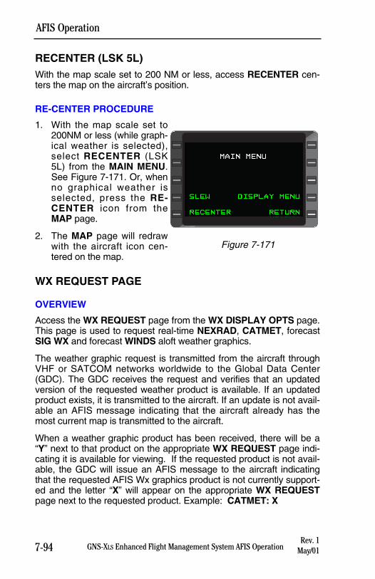
RECENTER (LSK 5L)With the map scale set to 200 NM or less, access RECENTER cen-ters the map on the aircraft’s position.
RE-CENTER PROCEDURE
1. With the map scale set to200NM or less (while graph-ical weather is selected),select RECENTER (LSK5L) from the MAIN MENU.See Figure 7-171. Or, whenno graphical weather isselected, press the RE-CENTER icon from theMAP page.
2. The MAP page will redrawwith the aircraft icon cen-tered on the map.
WX REQUEST PAGE
OVERVIEW
Access the WX REQUEST page from the WX DISPLAY OPTS page.This page is used to request real-time NEXRAD, CATMET, forecastSIG WX and forecast WINDS aloft weather graphics.
The weather graphic request is transmitted from the aircraft throughVHF or SATCOM networks worldwide to the Global Data Center(GDC). The GDC receives the request and verifies that an updatedversion of the requested weather product is available. If an updatedproduct exists, it is transmitted to the aircraft. If an update is not avail-able an AFIS message indicating that the aircraft already has themost current map is transmitted to the aircraft.
When a weather graphic product has been received, there will be a“Y” next to that product on the appropriate WX REQUEST page indi-cating it is available for viewing. If the requested product is not avail-able, the GDC will issue an AFIS message to the aircraft indicatingthat the requested AFIS Wx graphics product is not currently support-ed and the letter “X” will appear on the appropriate WX REQUESTpage next to the requested product. Example: CATMET: X
7-94 GNS-XLS Enhanced Flight Management System AFIS Operation
AFIS Operation
Rev. 1May/01
NEXRAD
WX REQUEST
CATMET
SIG WX
WINDS PENDING
RETURN
Figure 7-171
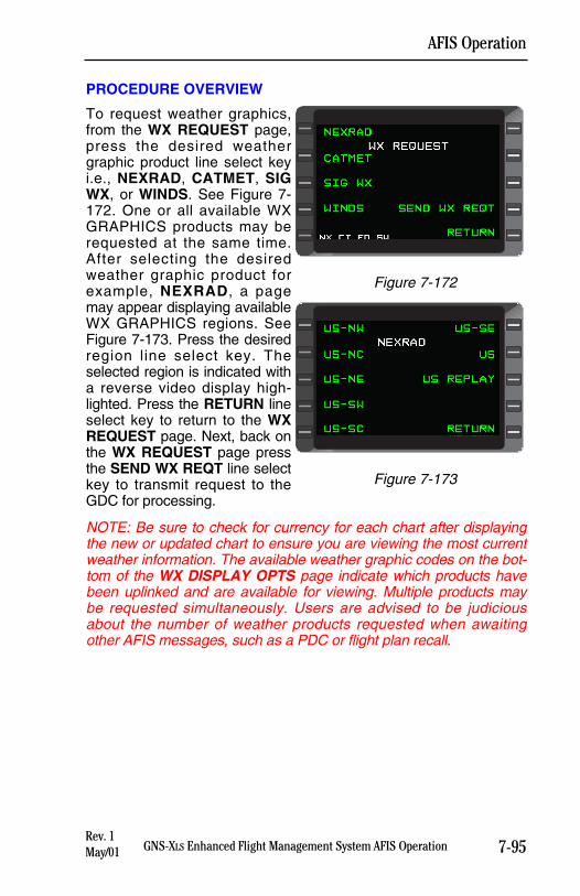
7-95GNS-XLS Enhanced Flight Management System AFIS Operation
AFIS Operation
PROCEDURE OVERVIEW
To request weather graphics,from the WX REQUEST page,press the desired weathergraphic product line select keyi.e., NEXRAD, CATMET, SIGWX, or WINDS. See Figure 7-172. One or all available WXGRAPHICS products may berequested at the same time.After selecting the desiredweather graphic product forexample, NEXRAD, a pagemay appear displaying availableWX GRAPHICS regions. SeeFigure 7-173. Press the desiredregion line select key. Theselected region is indicated witha reverse video display high-lighted. Press the RETURN lineselect key to return to the WXREQUEST page. Next, back onthe WX REQUEST page pressthe SEND WX REQT line selectkey to transmit request to theGDC for processing.
NOTE: Be sure to check for currency for each chart after displayingthe new or updated chart to ensure you are viewing the most currentweather information. The available weather graphic codes on the bot-tom of the WX DISPLAY OPTS page indicate which products havebeen uplinked and are available for viewing. Multiple products maybe requested simultaneously. Users are advised to be judiciousabout the number of weather products requested when awaitingother AFIS messages, such as a PDC or flight plan recall.
Rev. 1May/01
NEXRAD
WX REQUEST
CATMET
SIG WX
WINDS SEND WX REQT
RETURN
Figure 7-172
NEXRAD
WX REQUEST
CATMET
SIG WX
WINDS PENDING
RETURN
Figure 7-173
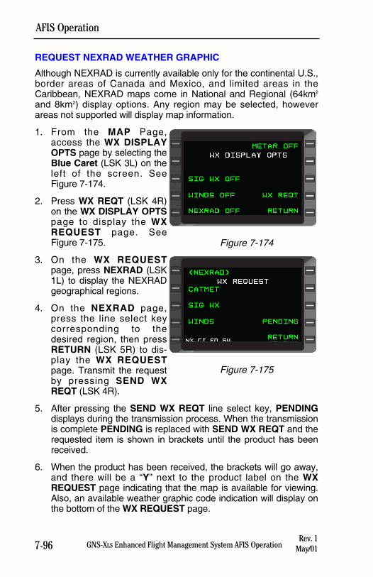
7-96 GNS-XLS Enhanced Flight Management System AFIS Operation
AFIS Operation
REQUEST NEXRAD WEATHER GRAPHIC
Although NEXRAD is currently available only for the continental U.S.,border areas of Canada and Mexico, and limited areas in theCaribbean, NEXRAD maps come in National and Regional (64km2
and 8km2) display options. Any region may be selected, howeverareas not supported will display map information.
1. From the MAP Page,access the WX DISPLAYOPTS page by selecting theBlue Caret (LSK 3L) on theleft of the screen. SeeFigure 7-174.
2. Press WX REQT (LSK 4R)on the WX DISPLAY OPTSpage to display the WXREQUEST page. SeeFigure 7-175.
3. On the WX REQUESTpage, press NEXRAD (LSK1L) to display the NEXRADgeographical regions.
4. On the NEXRAD page,press the line select keycorresponding to thedesired region, then pressRETURN (LSK 5R) to dis-play the WX REQUESTpage. Transmit the requestby pressing SEND WXREQT (LSK 4R).
5. After pressing the SEND WX REQT line select key, PENDINGdisplays during the transmission process. When the transmissionis complete PENDING is replaced with SEND WX REQT and therequested item is shown in brackets until the product has beenreceived.
6. When the product has been received, the brackets will go away,and there will be a “Y” next to the product label on the WXREQUEST page indicating that the map is available for viewing.Also, an available weather graphic code indication will display onthe bottom of the WX REQUEST page.
Rev. 1May/01
METAR OFF
WX DISPLAY OPTS
SIG WX OFF
WINDS OFF WX REQT
NEXRAD OFF RETURN
Figure 7-175
NEXRAD
WX REQUEST
CATMET
SIG WX
WINDS PENDING
RETURN
Figure 7-174
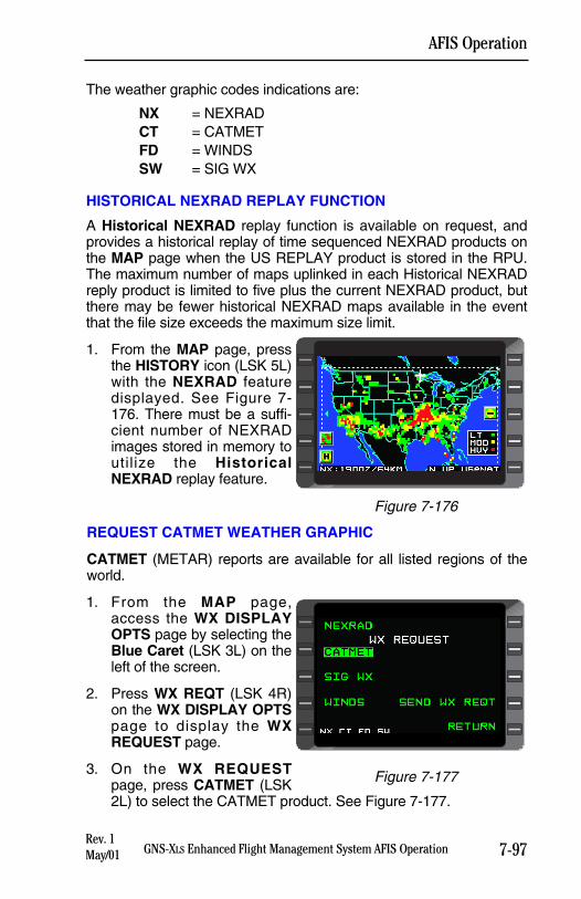
7-97GNS-XLS Enhanced Flight Management System AFIS Operation
AFIS Operation
The weather graphic codes indications are:
NX = NEXRADCT = CATMETFD = WINDSSW = SIG WX
HISTORICAL NEXRAD REPLAY FUNCTION
A Historical NEXRAD replay function is available on request, andprovides a historical replay of time sequenced NEXRAD products onthe MAP page when the US REPLAY product is stored in the RPU.The maximum number of maps uplinked in each Historical NEXRADreply product is limited to five plus the current NEXRAD product, butthere may be fewer historical NEXRAD maps available in the eventthat the file size exceeds the maximum size limit.
1. From the MAP page, pressthe HISTORY icon (LSK 5L)with the NEXRAD featuredisplayed. See Figure 7-176. There must be a suffi-cient number of NEXRADimages stored in memory toutilize the HistoricalNEXRAD replay feature.
REQUEST CATMET WEATHER GRAPHIC
CATMET (METAR) reports are available for all listed regions of theworld.
1. From the MAP page,access the WX DISPLAYOPTS page by selecting theBlue Caret (LSK 3L) on theleft of the screen.
2. Press WX REQT (LSK 4R)on the WX DISPLAY OPTSpage to display the WXREQUEST page.
3. On the WX REQUESTpage, press CATMET (LSK2L) to select the CATMET product. See Figure 7-177.
Rev. 1May/01
Figure 7-177
NEXRAD
WX REQUEST
CATMET
SIG WX
WINDS SEND WX REQT
RETURN
Figure 7-176
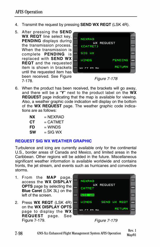
4. Transmit the request by pressing SEND WX REQT (LSK 4R).
5. After pressing the SENDWX REQT line select key,PENDING displays duringthe transmission process.When the transmission iscomplete PENDING isreplaced with SEND WXREQT and the requesteditem is shown in bracketsuntil the requested item hasbeen received. See Figure7-178.
6. When the product has been received, the brackets will go away,and there will be a “Y” next to the product label on the WXREQUEST page indicating that the map is available for viewing.Also, a weather graphic code indication will display on the bottomof the WX REQUEST page. The weather graphic code indica-tions are as follows:
NX = NEXRADCT = CATMETFD = WINDSSW = SIG WX
REQUEST SIG WX WEATHER GRAPHIC
Turbulence and icing are currently available only for the continentalU.S., border areas of Canada and Mexico, and limited areas in theCaribbean. Other regions will be added in the future. Miscellaneoussignificant weather information is available worldwide and containsfronts, the jet stream, and events such as hurricanes and convectivestorms.
1. From the MAP page,access the WX DISPLAYOPTS page by selecting theBlue Caret (LSK 3L) on theleft of the screen.
2. Press WX REQT (LSK 4R)on the WX DISPLAY OPTSpage to display the WXREQUEST page. SeeFigure 7-179.
7-98 GNS-XLS Enhanced Flight Management System AFIS Operation
AFIS Operation
METAR ON
WX DISPLAY OPTS
REGL DISPLAY
SIG WX OFF LIST METAR
WINDS OFF WX REQT
NEXRAD OFF RETURN
Figure 7-179
Rev. 1May/01
Figure 7-178
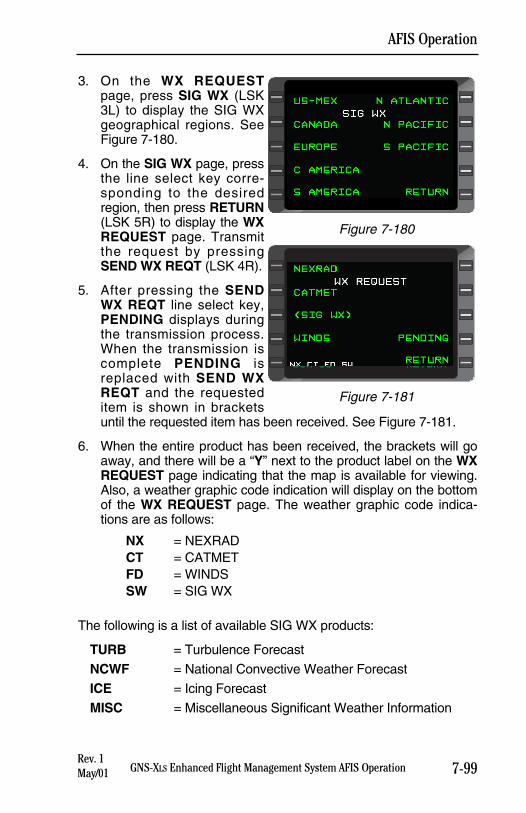
7-99GNS-XLS Enhanced Flight Management System AFIS Operation
AFIS Operation
3. On the WX REQUESTpage, press SIG WX (LSK3L) to display the SIG WXgeographical regions. SeeFigure 7-180.
4. On the SIG WX page, pressthe line select key corre-sponding to the desiredregion, then press RETURN(LSK 5R) to display the WXREQUEST page. Transmitthe request by pressingSEND WX REQT (LSK 4R).
5. After pressing the SENDWX REQT line select key,PENDING displays duringthe transmission process.When the transmission iscomplete PENDING isreplaced with SEND WXREQT and the requesteditem is shown in bracketsuntil the requested item has been received. See Figure 7-181.
6. When the entire product has been received, the brackets will goaway, and there will be a “Y” next to the product label on the WXREQUEST page indicating that the map is available for viewing.Also, a weather graphic code indication will display on the bottomof the WX REQUEST page. The weather graphic code indica-tions are as follows:
NX = NEXRADCT = CATMETFD = WINDSSW = SIG WX
The following is a list of available SIG WX products:
TURB = Turbulence Forecast
NCWF = National Convective Weather Forecast
ICE = Icing Forecast
MISC = Miscellaneous Significant Weather Information
Rev. 1May/01
Figure 7-180
USA-NW USA-SE
LOAD US MAP
USA-NC ALASKA
USA-NE USANATL
USA-SW MEXICO
USA-SC RETURN
Figure 7-181
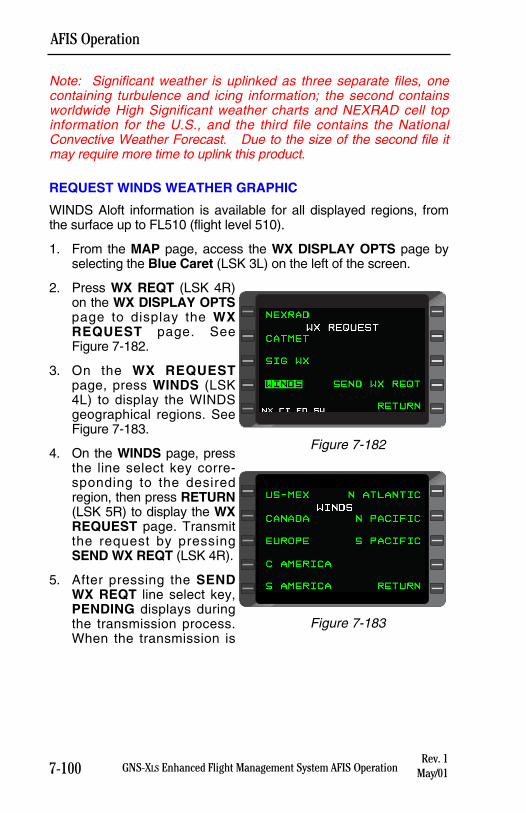
7-100 GNS-XLS Enhanced Flight Management System AFIS Operation
AFIS Operation
Note: Significant weather is uplinked as three separate files, onecontaining turbulence and icing information; the second containsworldwide High Significant weather charts and NEXRAD cell topinformation for the U.S., and the third file contains the NationalConvective Weather Forecast. Due to the size of the second file itmay require more time to uplink this product.
REQUEST WINDS WEATHER GRAPHIC
WINDS Aloft information is available for all displayed regions, fromthe surface up to FL510 (flight level 510).
1. From the MAP page, access the WX DISPLAY OPTS page byselecting the Blue Caret (LSK 3L) on the left of the screen.
2. Press WX REQT (LSK 4R)on the WX DISPLAY OPTSpage to display the WXREQUEST page. SeeFigure 7-182.
3. On the WX REQUESTpage, press WINDS (LSK4L) to display the WINDSgeographical regions. SeeFigure 7-183.
4. On the WINDS page, pressthe line select key corre-sponding to the desiredregion, then press RETURN(LSK 5R) to display the WXREQUEST page. Transmitthe request by pressingSEND WX REQT (LSK 4R).
5. After pressing the SENDWX REQT line select key,PENDING displays duringthe transmission process.When the transmission is
Rev. 1May/01
Figure 7-183
METAR ON
WX DISPLAY OPTS
REGL DISPLAY
SIG WX OFF LIST METAR
WINDS OFF WX REQT
NEXRAD OFF RETURN
Figure 7-182
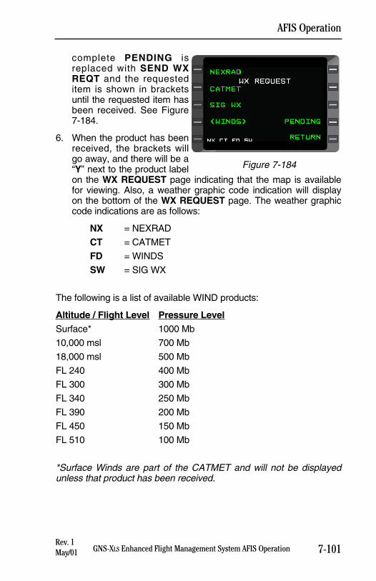
7-101GNS-XLS Enhanced Flight Management System AFIS Operation
AFIS Operation
complete PENDING isreplaced with SEND WXREQT and the requesteditem is shown in bracketsuntil the requested item hasbeen received. See Figure7-184.
6. When the product has beenreceived, the brackets willgo away, and there will be a“Y” next to the product labelon the WX REQUEST page indicating that the map is availablefor viewing. Also, a weather graphic code indication will displayon the bottom of the WX REQUEST page. The weather graphiccode indications are as follows:
NX = NEXRAD
CT = CATMET
FD = WINDS
SW = SIG WX
The following is a list of available WIND products:
Altitude / Flight Level Pressure LevelSurface* 1000 Mb
10,000 msl 700 Mb
18,000 msl 500 Mb
FL 240 400 Mb
FL 300 300 Mb
FL 340 250 Mb
FL 390 200 Mb
FL 450 150 Mb
FL 510 100 Mb
*Surface Winds are part of the CATMET and will not be displayedunless that product has been received.
Rev. 1May/01
Figure 7-184
7-102 GNS-XLS Enhanced Flight Management System AFIS Operation
AFIS Operation
Wind speed is coded in the following manner for all but surfacewinds:
Color Wind SpeedGreen 0 - 30ktsYellow 30 - 60ktsRed > 61kts
For surface winds, wind speed is coded in the following manner:
Color Wind SpeedGreen 0 - 10ktsYellow 10 - 20ksRed > 20kts
NOTE: Although WIND data is available worldwide, occasionallyWIND data is not available at all the listed altitudes in every region ofthe world due to a lack of source data. When WIND data is not avail-able for a particular altitude or flight level, that map will display thegeographic image without the WIND overlay.
DISPLAY WX GRAPHICS
When the initial weather graphic request is received by the RPU, theavailable weather graphic products are accessed from the WX DIS-PLAY OPTS page. Weather graphics received by the aircraft are dis-played with an OFF just to the right. OFF indicates that the weathergraphic product is available but is not turned on. By pressing the cor-responding line select key next to the received weather graphic prod-uct, OFF will toggle to ON, enabling the weather graphic to be dis-played. But, before displaying the weather graphic product, firstselect the scale of the weather graphic. Only one weather graphicsproduct at a time may be displayed. For example, toggling WINDSON will toggle NEXRAD OFF.
With any graphical weather selected and the map scale set to 100NM or greater, press the Scroll icon (LSK 4L) on the MAP page toscroll through all the weather graphic products selected ON. Toascertain the timeliness of the graphical weather, check the effectivitytimes at the bottom of each individual product. Uplinked AFISGraphical Weather products that are older than 6 hours will deleteautomatically to prevent unintended use.
NOTE: If the aircraft position or route of flight (depicted from theactive flight plan in the GNS-XLS) is located in the selected region itis also displayed in weather graphic page.
Rev. 1May/01
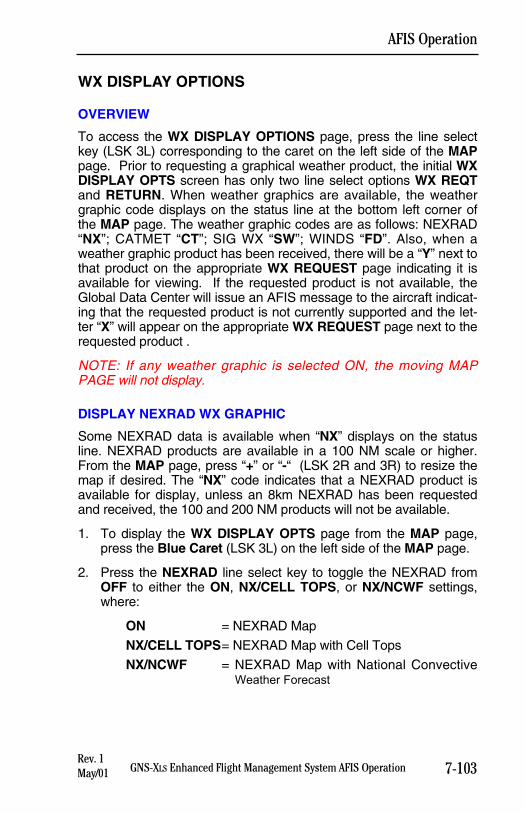
7-103GNS-XLS Enhanced Flight Management System AFIS Operation
AFIS Operation
WX DISPLAY OPTIONS
OVERVIEW
To access the WX DISPLAY OPTIONS page, press the line selectkey (LSK 3L) corresponding to the caret on the left side of the MAPpage. Prior to requesting a graphical weather product, the initial WXDISPLAY OPTS screen has only two line select options WX REQTand RETURN. When weather graphics are available, the weathergraphic code displays on the status line at the bottom left corner ofthe MAP page. The weather graphic codes are as follows: NEXRAD“NX”; CATMET “CT”; SIG WX “SW”; WINDS “FD”. Also, when aweather graphic product has been received, there will be a “Y” next tothat product on the appropriate WX REQUEST page indicating it isavailable for viewing. If the requested product is not available, theGlobal Data Center will issue an AFIS message to the aircraft indicat-ing that the requested product is not currently supported and the let-ter “X” will appear on the appropriate WX REQUEST page next to therequested product .
NOTE: If any weather graphic is selected ON, the moving MAPPAGE will not display.
DISPLAY NEXRAD WX GRAPHIC
Some NEXRAD data is available when “NX” displays on the statusline. NEXRAD products are available in a 100 NM scale or higher.From the MAP page, press “+” or “-“ (LSK 2R and 3R) to resize themap if desired. The “NX” code indicates that a NEXRAD product isavailable for display, unless an 8km NEXRAD has been requestedand received, the 100 and 200 NM products will not be available.
1. To display the WX DISPLAY OPTS page from the MAP page,press the Blue Caret (LSK 3L) on the left side of the MAP page.
2. Press the NEXRAD line select key to toggle the NEXRAD fromOFF to either the ON, NX/CELL TOPS, or NX/NCWF settings,where:
ON = NEXRAD Map
NX/CELL TOPS= NEXRAD Map with Cell Tops
NX/NCWF = NEXRAD Map with National ConvectiveWeather Forecast
Rev. 1May/01
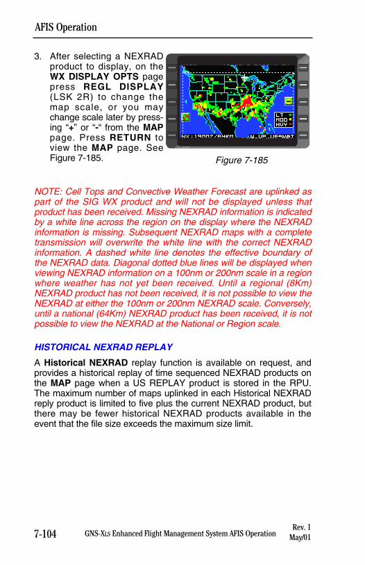
7-104 GNS-XLS Enhanced Flight Management System AFIS Operation
AFIS Operation
3. After selecting a NEXRADproduct to display, on theWX DISPLAY OPTS pagepress REGL DISPLAY(LSK 2R) to change themap scale, or you maychange scale later by press-ing “+” or “-“ from the MAPpage. Press RETURN toview the MAP page. SeeFigure 7-185.
NOTE: Cell Tops and Convective Weather Forecast are uplinked aspart of the SIG WX product and will not be displayed unless thatproduct has been received. Missing NEXRAD information is indicatedby a white line across the region on the display where the NEXRADinformation is missing. Subsequent NEXRAD maps with a completetransmission will overwrite the white line with the correct NEXRADinformation. A dashed white line denotes the effective boundary ofthe NEXRAD data. Diagonal dotted blue lines will be displayed whenviewing NEXRAD information on a 100nm or 200nm scale in a regionwhere weather has not yet been received. Until a regional (8Km)NEXRAD product has not been received, it is not possible to view theNEXRAD at either the 100nm or 200nm NEXRAD scale. Conversely,until a national (64Km) NEXRAD product has been received, it is notpossible to view the NEXRAD at the National or Region scale.
HISTORICAL NEXRAD REPLAY
A Historical NEXRAD replay function is available on request, andprovides a historical replay of time sequenced NEXRAD products onthe MAP page when a US REPLAY product is stored in the RPU.The maximum number of maps uplinked in each Historical NEXRADreply product is limited to five plus the current NEXRAD product, butthere may be fewer historical NEXRAD products available in theevent that the file size exceeds the maximum size limit.
Rev. 1May/01
KSEA SEATTLE TACOMA INN 47 26.12 DAY:22W 122 18.58 TIME:23:31
WINDS:SW 10-15 KTS
CEILING:MVFR VISIBILITY:VFRFREEZING DANGER:LOW TMP/DEW SPREAD:LESS THAN 4C
PRESS ANY KEY
Figure 7-185
GNS-XLS Enhanced FMS with Regional Airline AFISRev. 1May/01
SECTION 8
REGIONAL AIRLINES
AFISAIRBORNE FLIGHT INFORMATION SYSTEM
This section applies exclusively to aircraft operating an AFIS systemDMU with part number 400-045500-0211 or 400-045500-2011.
The purpose of this section is to acquaint users of AFIS Flight Planand Weather Advisory Services with the equipment, its capabilities,and its operation. AFIS services are ADVISORY only, as they con-tain elements provided by the National Weather Service and informa-tion supplied by the pilot. Therefore, it is the responsibility of the pilotin command to exercise reasonable and prudent judgment in the useof these ADVISORY services.

GNS-XLS Enhanced FMS with Regional Airline AFISRev. 1
May/01
THIS PAGE INTENTIONALLY LEFT BLANK
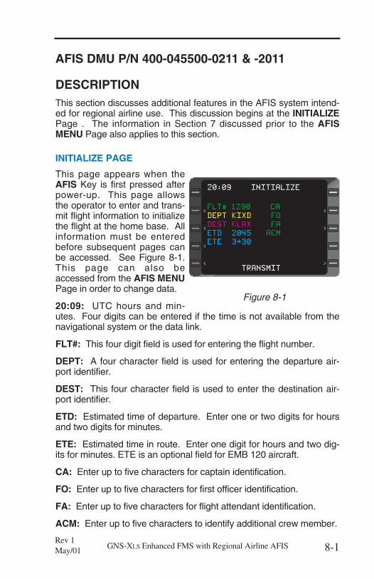
AFIS DMU P/N 400-045500-0211 & -2011
DESCRIPTIONThis section discusses additional features in the AFIS system intend-ed for regional airline use. This discussion begins at the INITIALIZEPage . The information in Section 7 discussed prior to the AFISMENU Page also applies to this section.
INITIALIZE PAGE
This page appears when theAFIS Key is first pressed afterpower-up. This page allowsthe operator to enter and trans-mit flight information to initializethe flight at the home base. Allinformation must be enteredbefore subsequent pages canbe accessed. See Figure 8-1.This page can also beaccessed from the AFIS MENUPage in order to change data.
20:09: UTC hours and min-utes. Four digits can be entered if the time is not available from thenavigational system or the data link.
FLT#: This four digit field is used for entering the flight number.
DEPT: A four character field is used for entering the departure air-port identifier.
DEST: This four character field is used to enter the destination air-port identifier.
ETD: Estimated time of departure. Enter one or two digits for hoursand two digits for minutes.
ETE: Estimated time in route. Enter one digit for hours and two dig-its for minutes. ETE is an optional field for EMB 120 aircraft.
CA: Enter up to five characters for captain identification.
FO: Enter up to five characters for first officer identification.
FA: Enter up to five characters for flight attendant identification.
ACM: Enter up to five characters to identify additional crew member.
8-1GNS-XLS Enhanced FMS with Regional Airline AFISRev 1May/01
>
>
FLT# 1290 CA
DEPT KIXD FO
DEST KLAX FA
ETD 2045 ACM
ETE 3+30
TRANSMIT
20:09 INITIALIZE
<
<
<
<
>
>
>
Figure 8-1
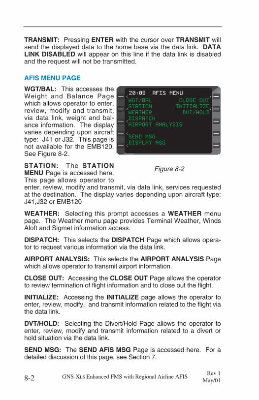
TRANSMIT: Pressing ENTER with the cursor over TRANSMIT willsend the displayed data to the home base via the data link. DATALINK DISABLED will appear on this line if the data link is disabledand the request will not be transmitted.
AFIS MENU PAGE
WGT/BAL: This accesses theWeight and Balance Pagewhich allows operator to enter,review, modify and transmit,via data link, weight and bal-ance information. The displayvaries depending upon aircrafttype: J41 or J32. This page isnot available for the EMB120.See Figure 8-2.
STATION: The STATIONMENU Page is accessed here.This page allows operator toenter, review, modify and transmit, via data link, services requestedat the destination. The display varies depending upon aircraft type:J41,J32 or EMB120
WEATHER: Selecting this prompt accesses a WEATHER menupage. The Weather menu page provides Terminal Weather, WindsAloft and Sigmet information access.
DISPATCH: This selects the DISPATCH Page which allows opera-tor to request various information via the data link.
AIRPORT ANALYSIS: This selects the AIRPORT ANALYSIS Pagewhich allows operator to transmit airport information.
CLOSE OUT: Accessing the CLOSE OUT Page allows the operatorto review termination of flight information and to close out the flight.
INITIALIZE: Accessing the INITIALIZE page allows the operator toenter, review, modify, and transmit information related to the flight viathe data link.
DVT/HOLD: Selecting the Divert/Hold Page allows the operator toenter, review, modify and transmit information related to a divert orhold situation via the data link.
SEND MSG: The SEND AFIS MSG Page is accessed here. For adetailed discussion of this page, see Section 7.
8-2 GNS-XLS Enhanced FMS with Regional Airline AFISRev 1
May/01
>
WGT/BAL CLOSE OUT
STATION INITIALIZE
WEATHER DVT/HOLD
DISPATCH
AIRPORT ANALYSIS
SEND MSG
DISPLAY MSG
20:09 AFIS MENU
<
><
<
< >
<
Figure 8-2
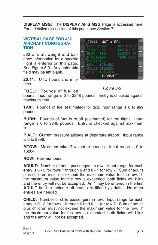
DISPLAY MSG: The DISPLAY AFIS MSG Page is accessed here.For a detailed discussion of this page, see Section 7.
WGT/BAL PAGE FOR J32AIRCRAFT CONFIGURA-TION
J32 aircraft weight and bal-ance information for a specificflight is entered on this page.See Figure 8-3. Any enterablefield may be left blank.
20:11: UTC hours and min-utes.
FUEL: Pounds of fuel onboard. Input range is 0 to 3248 pounds. Entry is checked againstmaximum limit.
TAXI: Pounds of fuel (estimated) for taxi. Input range is 0 to 999pounds.
BURN: Pounds of fuel burn-off (estimated) for the flight. Inputrange is 0 to 3248 pounds. Entry is checked against maximumlimit.
P ALT: Current pressure altitude at departure airport. Input rangeis 0 to 9999.
MTOW: Maximum takeoff weight in pounds. Input range is 0 to16204.
ROW: Row numbers.
ADULT: Number of adult passengers in row. Input range for eachentry is 0 - 3 for rows 1 through 6 and 0 - 1 for row 7. Sum of adultsplus children must not exceed the maximum value for the row. Ifthe maximum value for the row is exceeded, both fields will blinkand the entry will not be accepted. An * may be entered in the firstADULT field to indicate all seats are filled by adults. No otherentries are needed.
CHILD: Number of child passengers in row. Input range for eachentry is 0 - 3 for rows 1 through 6 and 0 - 1 for row 7. Sum of adultsplus children must not exceed the maximum value for the row. Ifthe maximum value for the row is exceeded, both fields will blinkand the entry will not be accepted.
8-3GNS-XLS Enhanced FMS with Regional Airline AFISRev 1May/01
FUEL 1300 AFT WT130
TAXI 80 POD WT 50
BURN 800 CLSTWT 10
P ALT2992 TEMP C+28
MTOW15189
ROW 1234567
ADULT 2123021
CHILD 1210310
TRANSMIT
20:11 WGT & BAL
<
><
<
< >
<
>
>
Figure 8-3
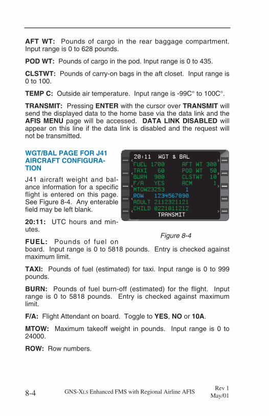
AFT WT: Pounds of cargo in the rear baggage compartment.Input range is 0 to 628 pounds.
POD WT: Pounds of cargo in the pod. Input range is 0 to 435.
CLSTWT: Pounds of carry-on bags in the aft closet. Input range is0 to 100.
TEMP C: Outside air temperature. Input range is -99C° to 100C°.
TRANSMIT: Pressing ENTER with the cursor over TRANSMIT willsend the displayed data to the home base via the data link and theAFIS MENU page will be accessed. DATA LINK DISABLED willappear on this line if the data link is disabled and the request willnot be transmitted.
WGT/BAL PAGE FOR J41AIRCRAFT CONFIGURA-TION
J41 aircraft weight and bal-ance information for a specificflight is entered on this page.See Figure 8-4. Any enterablefield may be left blank.
20:11: UTC hours and min-utes.
FUEL: Pounds of fuel onboard. Input range is 0 to 5818 pounds. Entry is checked againstmaximum limit.
TAXI: Pounds of fuel (estimated) for taxi. Input range is 0 to 999pounds.
BURN: Pounds of fuel burn-off (estimated) for the flight. Inputrange is 0 to 5818 pounds. Entry is checked against maximumlimit.
F/A: Flight Attendant on board. Toggle to YES, NO or 10A.
MTOW: Maximum takeoff weight in pounds. Input range is 0 to24000.
ROW: Row numbers.
8-4 GNS-XLS Enhanced FMS with Regional Airline AFISRev 1
May/01
FUEL 1700 AFT WT 300
TAXI 60 POD WT 50
BURN 900 CLSTWT 10
F/A YES ACM 1
MTOW23253 1
ROW 1234567890
ADULT 2112321121
CHILD 0221011212
TRANSMIT
20:11 WGT & BAL
<
><
<
< >
<
>
>
Figure 8-4
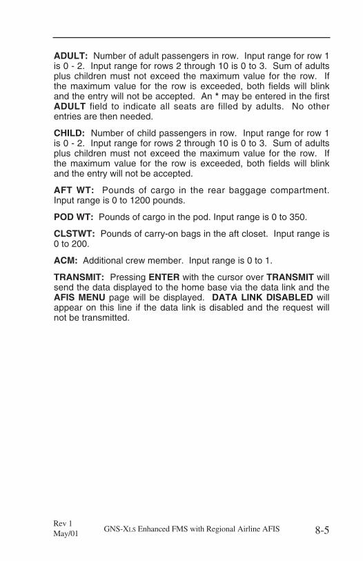
ADULT: Number of adult passengers in row. Input range for row 1is 0 - 2. Input range for rows 2 through 10 is 0 to 3. Sum of adultsplus children must not exceed the maximum value for the row. Ifthe maximum value for the row is exceeded, both fields will blinkand the entry will not be accepted. An * may be entered in the firstADULT field to indicate all seats are filled by adults. No otherentries are then needed.
CHILD: Number of child passengers in row. Input range for row 1is 0 - 2. Input range for rows 2 through 10 is 0 to 3. Sum of adultsplus children must not exceed the maximum value for the row. Ifthe maximum value for the row is exceeded, both fields will blinkand the entry will not be accepted.
AFT WT: Pounds of cargo in the rear baggage compartment.Input range is 0 to 1200 pounds.
POD WT: Pounds of cargo in the pod. Input range is 0 to 350.
CLSTWT: Pounds of carry-on bags in the aft closet. Input range is0 to 200.
ACM: Additional crew member. Input range is 0 to 1.
TRANSMIT: Pressing ENTER with the cursor over TRANSMIT willsend the data displayed to the home base via the data link and theAFIS MENU page will be displayed. DATA LINK DISABLED willappear on this line if the data link is disabled and the request willnot be transmitted.
8-5GNS-XLS Enhanced FMS with Regional Airline AFISRev 1May/01
STATION MENU PAGE FORJ32 AIRCRAFT CONFIGU-RATION
Desired services at the desti-nation for the J32 aircraft areentered on this page. SeeFigure 8-5. Any enterable fieldmay be left blank.
20:21: UTC hours and min-utes.
ETA: Estimated UTC time ofarrival. Input range is 0 to 23 hours and 0 to 59 minutes.
FUEL: Select if fuel service is needed. Enter Y for yes or N for no.
DEICE: Select if deicing service is needed. Enter Y for yes or Nfor no.
GPU: Select if a ground power unit is needed. Enter Y for yes or Nfor no.
DETAILING: Select if detailing service is needed. Enter Y for yesor N for no.
WINDSHIELD: Select if windshield service is needed. Enter Y foryes or N for no.
UM: Enter the number of unaccompanied minors. Input range is 0to 99.
WC: Enter the number of wheel chairs required.
A: Enter the number of aisle type wheel chairs required. Inputrange is 0 to 99.
S: Enter the number of standard type wheel chairs required. Inputrange is 0 to 99.
Two lines of free text can be entered with a maximum of 20alpha/numeric characters for each line.
TRANSMIT: Press ENTER with the cursor over TRANSMIT tosend the displayed data via the data link and the AFIS MENU pagewill be displayed. DATA LINK DISABLED will appear on this line ifthe data link is disabled and the request will not be transmitted.
8-6 GNS-XLS Enhanced FMS with Regional Airline AFISRev 1
May/01
20:21 STATION MENU
><
<
< >
<
>
>
>
ETA 2215 DETAILING N
FUEL Y WINDSHIELD Y
DEICE N
GPU Y
UM 1
s WC 3 A 12 S
TRANSMIT
Figure 8-5
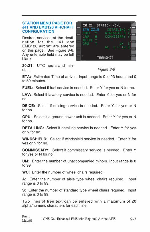
STATION MENU PAGE FORJ41 AND EMB120 AIRCRAFTCONFIGURATION
Desired services at the desti-nation for the J41 andEMB120 aircraft are enteredon this page. See Figure 8-6.Any enterable field may be leftblank.
20:21: UTC hours and min-utes.
ETA: Estimated Time of arrival. Input range is 0 to 23 hours and 0to 59 minutes.
FUEL: Select if fuel service is needed. Enter Y for yes or N for no.
LAV: Select if lavatory service is needed. Enter Y for yes or N forno.
DEICE: Select if deicing service is needed. Enter Y for yes or Nfor no.
GPU: Select if a ground power unit is needed. Enter Y for yes or Nfor no.
DETAILING: Select if detailing service is needed. Enter Y for yesor N for no.
WINDSHIELD: Select if windshield service is needed. Enter Y foryes or N for no.
COMMISSARY: Select if commissary service is needed. Enter Yfor yes or N for no.
UM: Enter the number of unaccompanied minors. Input range is 0to 99.
WC: Enter the number of wheel chairs required.
A: Enter the number of aisle type wheel chairs required. Inputrange is 0 to 99.
S: Enter the number of standard type wheel chairs required. Inputrange is 0 to 99.
Two lines of free text can be entered with a maximum of 20alpha/numeric characters for each line.
8-7GNS-XLS Enhanced FMS with Regional Airline AFISRev 1May/01
ETA 2215 DETAILING N
FUEL Y WINDSHIELD Y
LAV N COMMISSARY Y
DEICE Y
GPU Y UM 1
WC 3 A 12 S
TRANSMIT
20:21 STATION MENU
><
<
< >
<
>
>
>
Figure 8-6
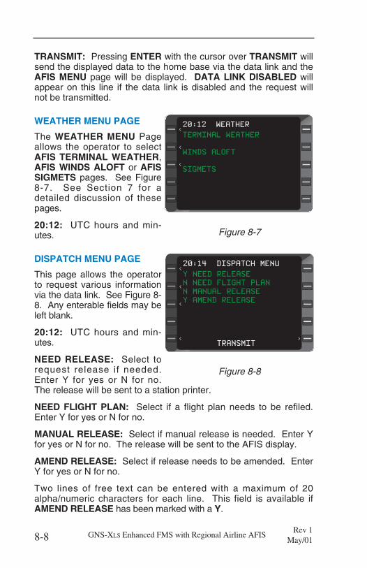
TRANSMIT: Pressing ENTER with the cursor over TRANSMIT willsend the displayed data to the home base via the data link and theAFIS MENU page will be displayed. DATA LINK DISABLED willappear on this line if the data link is disabled and the request willnot be transmitted.
WEATHER MENU PAGE
The WEATHER MENU Pageallows the operator to selectAFIS TERMINAL WEATHER,AFIS WINDS ALOFT or AFISSIGMETS pages. See Figure8-7. See Section 7 for adetailed discussion of thesepages.
20:12: UTC hours and min-utes.
DISPATCH MENU PAGE
This page allows the operatorto request various informationvia the data link. See Figure 8-8. Any enterable fields may beleft blank.
20:12: UTC hours and min-utes.
NEED RELEASE: Select torequest release if needed.Enter Y for yes or N for no.The release will be sent to a station printer.
NEED FLIGHT PLAN: Select if a flight plan needs to be refiled.Enter Y for yes or N for no.
MANUAL RELEASE: Select if manual release is needed. Enter Yfor yes or N for no. The release will be sent to the AFIS display.
AMEND RELEASE: Select if release needs to be amended. EnterY for yes or N for no.
Two lines of free text can be entered with a maximum of 20alpha/numeric characters for each line. This field is available ifAMEND RELEASE has been marked with a Y.
8-8 GNS-XLS Enhanced FMS with Regional Airline AFISRev 1
May/01
>
><
>
>
Y NEED RELEASE
N NEED FLIGHT PLAN
N MANUAL RELEASE
Y AMEND RELEASE
TRANSMIT
20:14 DISPATCH MENU
< >
<
<
<
Figure 8-8
< >
>
><
>
>
TERMINAL WEATHER
WINDS ALOFT
SIGMETS
20:12 WEATHER
<
<
<
Figure 8-7
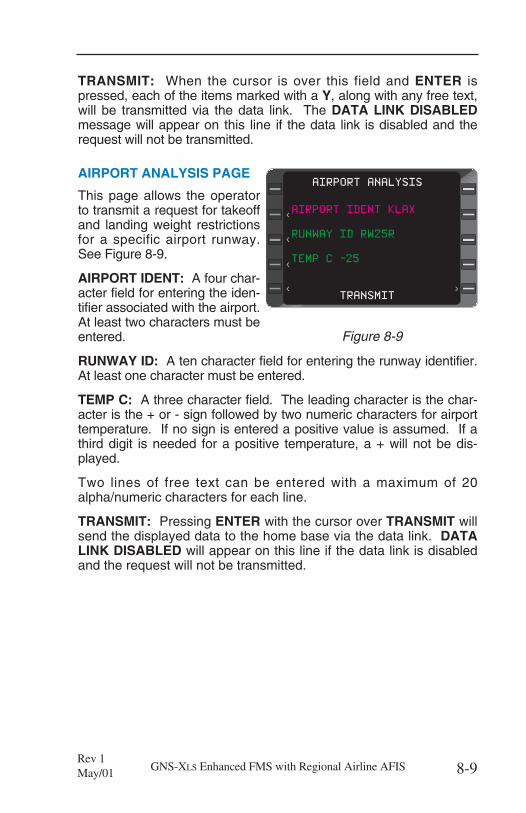
TRANSMIT: When the cursor is over this field and ENTER ispressed, each of the items marked with a Y, along with any free text,will be transmitted via the data link. The DATA LINK DISABLEDmessage will appear on this line if the data link is disabled and therequest will not be transmitted.
AIRPORT ANALYSIS PAGE
This page allows the operatorto transmit a request for takeoffand landing weight restrictionsfor a specific airport runway.See Figure 8-9.
AIRPORT IDENT: A four char-acter field for entering the iden-tifier associated with the airport.At least two characters must beentered.
RUNWAY ID: A ten character field for entering the runway identifier.At least one character must be entered.
TEMP C: A three character field. The leading character is the char-acter is the + or - sign followed by two numeric characters for airporttemperature. If no sign is entered a positive value is assumed. If athird digit is needed for a positive temperature, a + will not be dis-played.
Two lines of free text can be entered with a maximum of 20alpha/numeric characters for each line.
TRANSMIT: Pressing ENTER with the cursor over TRANSMIT willsend the displayed data to the home base via the data link. DATALINK DISABLED will appear on this line if the data link is disabledand the request will not be transmitted.
8-9GNS-XLS Enhanced FMS with Regional Airline AFISRev 1May/01
< >
AIRPORT IDENT KLAX
RUNWAY ID RW25R
TEMP C -25
TRANSMIT
AIRPORT ANALYSIS
<
<
<
<
>
Figure 8-9
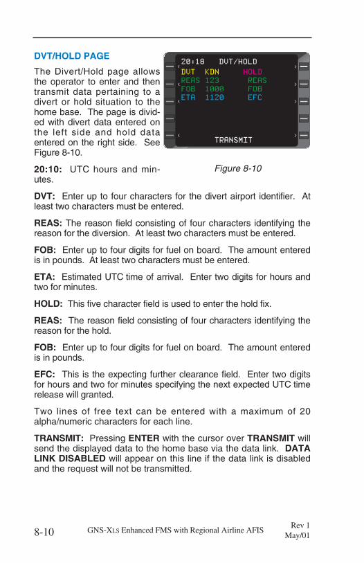
DVT/HOLD PAGE
The Divert/Hold page allowsthe operator to enter and thentransmit data pertaining to adivert or hold situation to thehome base. The page is divid-ed with divert data entered onthe left side and hold dataentered on the right side. SeeFigure 8-10.
20:10: UTC hours and min-utes.
DVT: Enter up to four characters for the divert airport identifier. Atleast two characters must be entered.
REAS: The reason field consisting of four characters identifying thereason for the diversion. At least two characters must be entered.
FOB: Enter up to four digits for fuel on board. The amount enteredis in pounds. At least two characters must be entered.
ETA: Estimated UTC time of arrival. Enter two digits for hours andtwo for minutes.
HOLD: This five character field is used to enter the hold fix.
REAS: The reason field consisting of four characters identifying thereason for the hold.
FOB: Enter up to four digits for fuel on board. The amount enteredis in pounds.
EFC: This is the expecting further clearance field. Enter two digitsfor hours and two for minutes specifying the next expected UTC timerelease will granted.
Two lines of free text can be entered with a maximum of 20alpha/numeric characters for each line.
TRANSMIT: Pressing ENTER with the cursor over TRANSMIT willsend the displayed data to the home base via the data link. DATALINK DISABLED will appear on this line if the data link is disabledand the request will not be transmitted.
8-10 GNS-XLS Enhanced FMS with Regional Airline AFISRev 1
May/01
>
< >
DVT KDN HOLD
REAS 123 REAS
FOB 1000 FOB
ETA 1120 EFC
TRANSMIT
20:18 DVT/HOLD
<
<
< >
>
>
< >
Figure 8-10
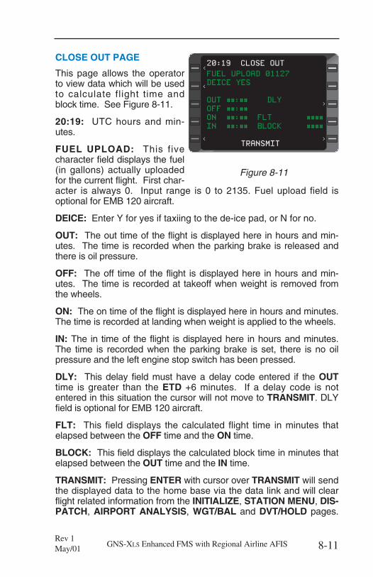
CLOSE OUT PAGE
This page allows the operatorto view data which will be usedto calculate flight time andblock time. See Figure 8-11.
20:19: UTC hours and min-utes.
FUEL UPLOAD: This fivecharacter field displays the fuel(in gallons) actually uploadedfor the current flight. First char-acter is always 0. Input range is 0 to 2135. Fuel upload field isoptional for EMB 120 aircraft.
DEICE: Enter Y for yes if taxiing to the de-ice pad, or N for no.
OUT: The out time of the flight is displayed here in hours and min-utes. The time is recorded when the parking brake is released andthere is oil pressure.
OFF: The off time of the flight is displayed here in hours and min-utes. The time is recorded at takeoff when weight is removed fromthe wheels.
ON: The on time of the flight is displayed here in hours and minutes.The time is recorded at landing when weight is applied to the wheels.
IN: The in time of the flight is displayed here in hours and minutes.The time is recorded when the parking brake is set, there is no oilpressure and the left engine stop switch has been pressed.
DLY: This delay field must have a delay code entered if the OUTtime is greater than the ETD +6 minutes. If a delay code is notentered in this situation the cursor will not move to TRANSMIT. DLYfield is optional for EMB 120 aircraft.
FLT: This field displays the calculated flight time in minutes thatelapsed between the OFF time and the ON time.
BLOCK: This field displays the calculated block time in minutes thatelapsed between the OUT time and the IN time.
TRANSMIT: Pressing ENTER with cursor over TRANSMIT will sendthe displayed data to the home base via the data link and will clearflight related information from the INITIALIZE, STATION MENU, DIS-PATCH, AIRPORT ANALYSIS, WGT/BAL and DVT/HOLD pages.
8-11GNS-XLS Enhanced FMS with Regional Airline AFISRev 1May/01
>
><
>
<
< >
FUEL UPLOAD 01127
DEICE YES
OUT ##:## DLY
OFF ##:##
ON ##:## FLT ####
IN ##:## BLOCK ####
TRANSMIT
20:19 CLOSE OUT
<
< >
<
>
Figure 8-11

NEED TO CALL TIMES will appear on this line if the ON time and/orIN time have not been acknowledged.
SEND MSG PAGE
The Send Message Page is discussed in detail in Section 7.
DISPLAY MSG PAGE
The Display Message Page is discussed in detail in Section 7.
8-12 GNS-XLS Enhanced FMS with Regional Airline AFISRev 1
May/01
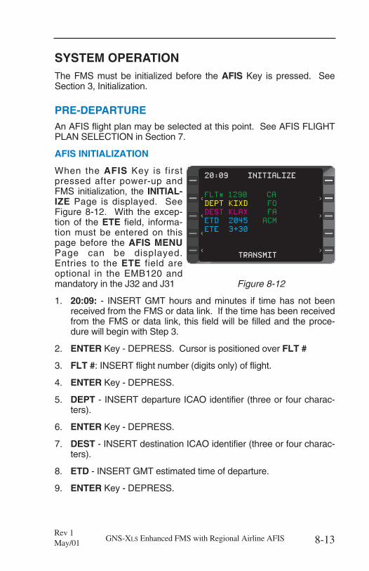
SYSTEM OPERATIONThe FMS must be initialized before the AFIS Key is pressed. SeeSection 3, Initialization.
PRE-DEPARTUREAn AFIS flight plan may be selected at this point. See AFIS FLIGHTPLAN SELECTION in Section 7.
AFIS INITIALIZATION
When the AFIS Key is firstpressed after power-up andFMS initialization, the INITIAL-IZE Page is displayed. SeeFigure 8-12. With the excep-tion of the ETE field, informa-tion must be entered on thispage before the AFIS MENUPage can be displayed.Entries to the ETE field areoptional in the EMB120 andmandatory in the J32 and J31
1. 20:09: - INSERT GMT hours and minutes if time has not beenreceived from the FMS or data link. If the time has been receivedfrom the FMS or data link, this field will be filled and the proce-dure will begin with Step 3.
2. ENTER Key - DEPRESS. Cursor is positioned over FLT #
3. FLT #: INSERT flight number (digits only) of flight.
4. ENTER Key - DEPRESS.
5. DEPT - INSERT departure ICAO identifier (three or four charac-ters).
6. ENTER Key - DEPRESS.
7. DEST - INSERT destination ICAO identifier (three or four charac-ters).
8. ETD - INSERT GMT estimated time of departure.
9. ENTER Key - DEPRESS.
8-13GNS-XLS Enhanced FMS with Regional Airline AFISRev 1May/01
>
>
FLT# 1290 CA
DEPT KIXD FO
DEST KLAX FA
ETD 2045 ACM
ETE 3+30
TRANSMIT
20:09 INITIALIZE
<
<
<
<
>
>
>
Figure 8-12
10. ETE - INSERT estimated time in route in hour and minutes. Thismay be left blank for EMB120 only.
11. ENTER Key - DEPRESS.
12. CA - INSERT the Captain’s identifier code or leave blank.
13. ENTER Key - DEPRESS. If the Captain identifier code is leftblank, the cursor will move to TRANSMIT when the key ispressed. If an entry is made, the cursor will move to the FO field.
14. FO - INSERT the First Officer’s identifier code or leave blank.
15. ENTER Key - DEPRESS. If the First Officer identifier code is leftblank, the cursor will will move to TRANSMIT when the key ispressed. If an entry is made, the cursor will move to the FA field.
16. FA - INSERT the Flight Attendant’s identifier code or leaveblank.
17. ENTER Key - DEPRESS. If the Flight Attendant identifier code isleft blank, the cursor will move to TRANSMIT when the key ispressed. If an entry is made, the cursor will move to the ACMfield.
18. ACM field - INSERT Additional Crew Member identifier code orleave blank.
NOTE: The Line Select Keys may be used at any time to enter orchange data.
19. ENTER Key - DEPRESS. The cursor is positioned over TRANS-MIT.
20. ENTER Key - DEPRESS for data link transmission. The flight isnow initialized and the AFIS MENU page is displayed. SeeFigure 8-13.
NOTE: If a DATA LINK DISABLED message appears when ENTERis pressed, the data link is not available. Wait for TRANSMIT toappear or notify maintenance of the problem.
8-14 GNS-XLS Enhanced FMS with Regional Airline AFISRev 1
May/01
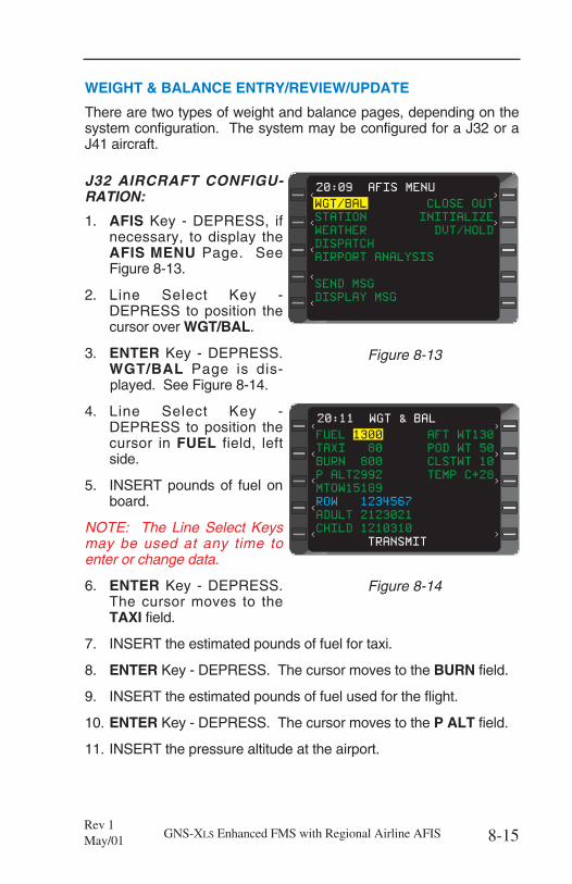
WEIGHT & BALANCE ENTRY/REVIEW/UPDATE
There are two types of weight and balance pages, depending on thesystem configuration. The system may be configured for a J32 or aJ41 aircraft.
J32 AIRCRAFT CONFIGU-RATION:
1. AFIS Key - DEPRESS, ifnecessary, to display theAFIS MENU Page. SeeFigure 8-13.
2. Line Select Key -DEPRESS to position thecursor over WGT/BAL.
3. ENTER Key - DEPRESS.WGT/BAL Page is dis-played. See Figure 8-14.
4. Line Select Key -DEPRESS to position thecursor in FUEL field, leftside.
5. INSERT pounds of fuel onboard.
NOTE: The Line Select Keysmay be used at any time toenter or change data.
6. ENTER Key - DEPRESS.The cursor moves to theTAXI field.
7. INSERT the estimated pounds of fuel for taxi.
8. ENTER Key - DEPRESS. The cursor moves to the BURN field.
9. INSERT the estimated pounds of fuel used for the flight.
10. ENTER Key - DEPRESS. The cursor moves to the P ALT field.
11. INSERT the pressure altitude at the airport.
8-15GNS-XLS Enhanced FMS with Regional Airline AFISRev 1May/01
20:11 WGT & BAL
<
><
<
< >
<
>
>
FUEL 1300 AFT WT130
TAXI 80 POD WT 50
BURN 800 CLSTWT 10
P ALT2992 TEMP C+28
MTOW15189
ROW 1234567
ADULT 2123021
CHILD 1210310
TRANSMIT
Figure 8-14
>
20:09 AFIS MENU
<
><
<
< >
<
WGT/BAL CLOSE OUT
STATION INITIALIZE
WEATHER DVT/HOLD
DISPATCH
AIRPORT ANALYSIS
SEND MSG
DISPLAY MSG
Figure 8-13

12. ENTER Key - DEPRESS. The cursor automatically moves to theMTOW field.
13. INSERT the maximum takeoff weight in pounds.
14. ENTER Key - DEPRESS. The cursor moves to the AFT WTfield.
15. INSERT pounds of cargo in the rear baggage compartment.
16. ENTER Key - DEPRESS. The cursor moves to the POD WTfield.
17. INSERT pounds of cargo in the pod.
18. ENTER Key - DEPRESS. The cursor moves to the CLSTWTfield.
19. INSERT pounds of cargo in the forward closet.
20. ENTER Key - DEPRESS. The cursor moves to the TEMP Cfield.
21. REVIEW the value in the temperature field or INSERT a value fortemperature. Enter a + or -, followed by one, two or three digits.The + sign is omitted if three digits are entered. Temperature isin degrees Celsius.
22. ENTER Key - DEPRESS. The cursor moves to the row 1ADULT field.
23. INSERT the number of adult passengers in row 1. Input rangefor each entry is 0 - 3 for rows 1 through 6 and 0 - 1 for row 7.Sum of adults plus children must not exceed the maximumvalue for the row. If the maximum value for the row is exceed-ed, both fields will blink and the entry will not be accepted. An *may be entered in the first ADULT field to indicate all seats arefilled with adults. No other entries in ADULT or CHILD fieldsare needed.
24. NXT Key - DEPRESS. The cursor moves to the row 1 CHILDfield.
25. INSERT the number of child passengers in row 1. Input rangefor each entry is 0 - 3 for rows 1 through 6 and 0 - 1 for row 7.Sum of adults plus children must not exceed the maximumvalue for the row. If the maximum value for the row is exceed-ed, both fields will blink and the entry will not be accepted.
26. NXT Key - DEPRESS. The cursor moves to the row 2 ADULTfield. Enter the appropriate number.
8-16 GNS-XLS Enhanced FMS with Regional Airline AFISRev 1
May/01
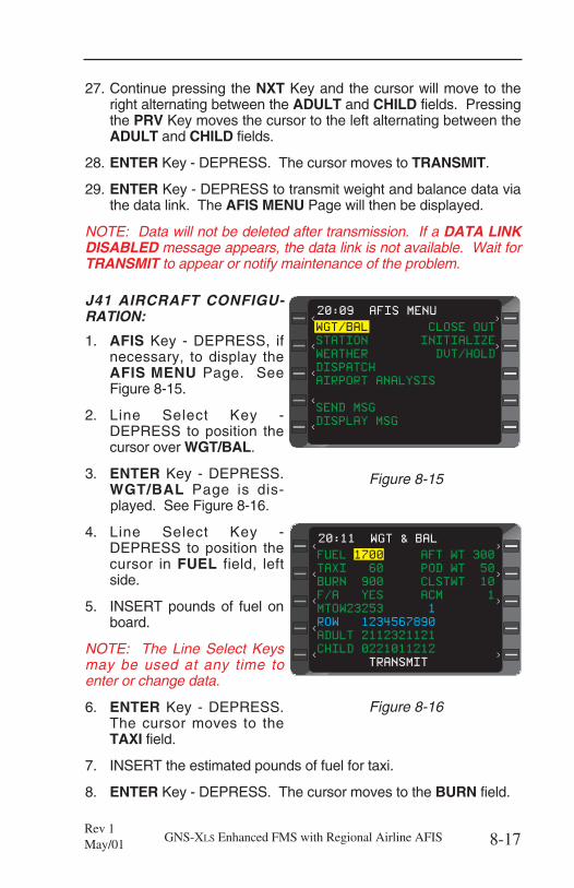
27. Continue pressing the NXT Key and the cursor will move to theright alternating between the ADULT and CHILD fields. Pressingthe PRV Key moves the cursor to the left alternating between theADULT and CHILD fields.
28. ENTER Key - DEPRESS. The cursor moves to TRANSMIT.
29. ENTER Key - DEPRESS to transmit weight and balance data viathe data link. The AFIS MENU Page will then be displayed.
NOTE: Data will not be deleted after transmission. If a DATA LINKDISABLED message appears, the data link is not available. Wait forTRANSMIT to appear or notify maintenance of the problem.
J41 AIRCRAFT CONFIGU-RATION:
1. AFIS Key - DEPRESS, ifnecessary, to display theAFIS MENU Page. SeeFigure 8-15.
2. Line Select Key -DEPRESS to position thecursor over WGT/BAL.
3. ENTER Key - DEPRESS.WGT/BAL Page is dis-played. See Figure 8-16.
4. Line Select Key -DEPRESS to position thecursor in FUEL field, leftside.
5. INSERT pounds of fuel onboard.
NOTE: The Line Select Keysmay be used at any time toenter or change data.
6. ENTER Key - DEPRESS.The cursor moves to theTAXI field.
7. INSERT the estimated pounds of fuel for taxi.
8. ENTER Key - DEPRESS. The cursor moves to the BURN field.
8-17GNS-XLS Enhanced FMS with Regional Airline AFISRev 1May/01
>
20:09 AFIS MENU
<
><
<
< >
<
WGT/BAL CLOSE OUT
STATION INITIALIZE
WEATHER DVT/HOLD
DISPATCH
AIRPORT ANALYSIS
SEND MSG
DISPLAY MSG
Figure 8-15
20:11 WGT & BAL
<
><
<
< >
<
>
>
FUEL 1700 AFT WT 300
TAXI 60 POD WT 50
BURN 900 CLSTWT 10
F/A YES ACM 1
MTOW23253 1
ROW 1234567890
ADULT 2112321121
CHILD 0221011212
TRANSMIT
Figure 8-16
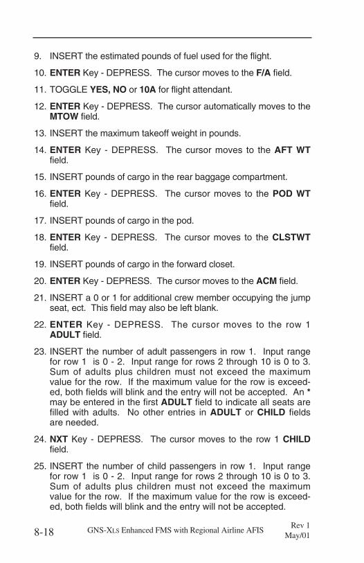
9. INSERT the estimated pounds of fuel used for the flight.
10. ENTER Key - DEPRESS. The cursor moves to the F/A field.
11. TOGGLE YES, NO or 10A for flight attendant.
12. ENTER Key - DEPRESS. The cursor automatically moves to theMTOW field.
13. INSERT the maximum takeoff weight in pounds.
14. ENTER Key - DEPRESS. The cursor moves to the AFT WTfield.
15. INSERT pounds of cargo in the rear baggage compartment.
16. ENTER Key - DEPRESS. The cursor moves to the POD WTfield.
17. INSERT pounds of cargo in the pod.
18. ENTER Key - DEPRESS. The cursor moves to the CLSTWTfield.
19. INSERT pounds of cargo in the forward closet.
20. ENTER Key - DEPRESS. The cursor moves to the ACM field.
21. INSERT a 0 or 1 for additional crew member occupying the jumpseat, ect. This field may also be left blank.
22. ENTER Key - DEPRESS. The cursor moves to the row 1ADULT field.
23. INSERT the number of adult passengers in row 1. Input rangefor row 1 is 0 - 2. Input range for rows 2 through 10 is 0 to 3.Sum of adults plus children must not exceed the maximumvalue for the row. If the maximum value for the row is exceed-ed, both fields will blink and the entry will not be accepted. An *may be entered in the first ADULT field to indicate all seats arefilled with adults. No other entries in ADULT or CHILD fieldsare needed.
24. NXT Key - DEPRESS. The cursor moves to the row 1 CHILDfield.
25. INSERT the number of child passengers in row 1. Input rangefor row 1 is 0 - 2. Input range for rows 2 through 10 is 0 to 3.Sum of adults plus children must not exceed the maximumvalue for the row. If the maximum value for the row is exceed-ed, both fields will blink and the entry will not be accepted.
8-18 GNS-XLS Enhanced FMS with Regional Airline AFISRev 1
May/01
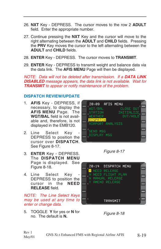
26. NXT Key - DEPRESS. The cursor moves to the row 2 ADULTfield. Enter the appropriate number.
27. Continue pressing the NXT Key and the cursor will move to theright alternating between the ADULT and CHILD fields. Pressingthe PRV Key moves the cursor to the left alternating between theADULT and CHILD fields.
28. ENTER Key - DEPRESS. The cursor moves to TRANSMIT.
29. ENTER Key - DEPRESS to transmit weight and balance data viathe data link. The AFIS MENU Page will then be displayed.
NOTE: Data will not be deleted after transmission. If a DATA LINKDISABLED message appears, the data link is not available. Wait forTRANSMIT to appear or notify maintenance of the problem.
DISPATCH REVIEW/UPDATE
1. AFIS Key - DEPRESS, ifnecessary, to display theAFIS MENU Page. TheWGT/BAL field is not avail-able and, therefore, is notdisplayed in the EMB120.
2. Line Select Key -DEPRESS to position thecursor over DISPATCH.See Figure 8-17.
3. ENTER Key - DEPRESS.The DISPATCH MENUPage is displayed. SeeFigure 8-18.
4. Line Select Key -DEPRESS to position thecursor in the NEEDRELEASE field.
NOTE: The Line Select Keysmay be used at any time toenter or change data.
5. TOGGLE Y for yes or N forno. The default is N.
8-19GNS-XLS Enhanced FMS with Regional Airline AFISRev 1May/01
>
20:09 AFIS MENU
<
><
<
< >
<
WGT/BAL CLOSE OUT
STATION INITIALIZE
WEATHER DVT/HOLD
DISPATCH
AIRPORT ANALYSIS
SEND MSG
DISPLAY MSG
Figure 8-17
>
><
>
>20:14 DISPATCH MENU
< >
<
<
<
Y NEED RELEASE
N NEED FLIGHT PLAN
N MANUAL RELEASE
Y AMEND RELEASE
TRANSMIT
Figure 8-18
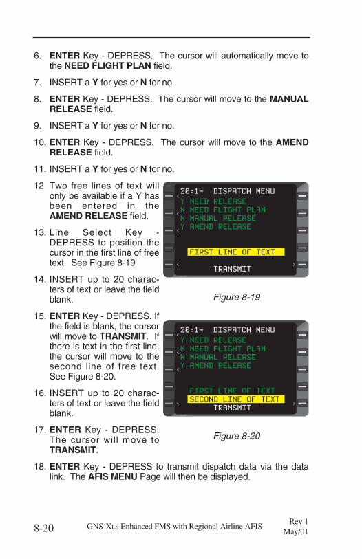
6. ENTER Key - DEPRESS. The cursor will automatically move tothe NEED FLIGHT PLAN field.
7. INSERT a Y for yes or N for no.
8. ENTER Key - DEPRESS. The cursor will move to the MANUALRELEASE field.
9. INSERT a Y for yes or N for no.
10. ENTER Key - DEPRESS. The cursor will move to the AMENDRELEASE field.
11. INSERT a Y for yes or N for no.
12 Two free lines of text willonly be available if a Y hasbeen entered in theAMEND RELEASE field.
13. Line Select Key -DEPRESS to position thecursor in the first line of freetext. See Figure 8-19
14. INSERT up to 20 charac-ters of text or leave the fieldblank.
15. ENTER Key - DEPRESS. Ifthe field is blank, the cursorwill move to TRANSMIT. Ifthere is text in the first line,the cursor will move to thesecond line of free text.See Figure 8-20.
16. INSERT up to 20 charac-ters of text or leave the fieldblank.
17. ENTER Key - DEPRESS.The cursor will move toTRANSMIT.
18. ENTER Key - DEPRESS to transmit dispatch data via the datalink. The AFIS MENU Page will then be displayed.
8-20 GNS-XLS Enhanced FMS with Regional Airline AFISRev 1
May/01
>
><
>
>20:14 DISPATCH MENU
< >
<
<
<
Y NEED RELEASE
N NEED FLIGHT PLAN
N MANUAL RELEASE
Y AMEND RELEASE
FIRST LINE OF TEXT
TRANSMIT
Figure 8-19
>
><
>
>20:14 DISPATCH MENU
< >
<
<
<
Y NEED RELEASE
N NEED FLIGHT PLAN
N MANUAL RELEASE
Y AMEND RELEASE
FIRST LINE OF TEXT
SECOND LINE OF TEXT
TRANSMIT
Figure 8-20
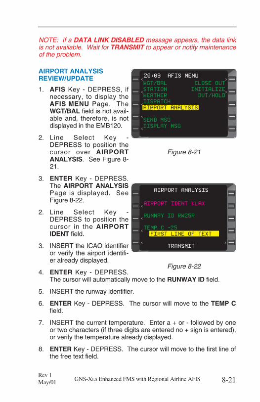
NOTE: If a DATA LINK DISABLED message appears, the data linkis not available. Wait for TRANSMIT to appear or notify maintenanceof the problem.
AIRPORT ANALYSISREVIEW/UPDATE
1. AFIS Key - DEPRESS, ifnecessary, to display theAFIS MENU Page. TheWGT/BAL field is not avail-able and, therefore, is notdisplayed in the EMB120.
2. Line Select Key -DEPRESS to position thecursor over AIRPORTANALYSIS. See Figure 8-21.
3. ENTER Key - DEPRESS.The AIRPORT ANALYSISPage is displayed. SeeFigure 8-22.
2. Line Select Key -DEPRESS to position thecursor in the AIRPORTIDENT field.
3. INSERT the ICAO identifieror verify the airport identifi-er already displayed.
4. ENTER Key - DEPRESS.The cursor will automatically move to the RUNWAY ID field.
5. INSERT the runway identifier.
6. ENTER Key - DEPRESS. The cursor will move to the TEMP Cfield.
7. INSERT the current temperature. Enter a + or - followed by oneor two characters (if three digits are entered no + sign is entered),or verify the temperature already displayed.
8. ENTER Key - DEPRESS. The cursor will move to the first line ofthe free text field.
8-21GNS-XLS Enhanced FMS with Regional Airline AFISRev 1May/01
< > AIRPORT ANALYSIS
<
<
<
<
>
AIRPORT IDENT KLAX
RUNWAY ID RW25R
TEMP C -25
FIRST LINE OF TEXT
TRANSMIT
Figure 8-22
>
20:09 AFIS MENU
<
><
<
< >
<
WGT/BAL CLOSE OUT
STATION INITIALIZE
WEATHER DVT/HOLD
DISPATCH
AIRPORT ANALYSIS
SEND MSG
DISPLAY MSG
Figure 8-21
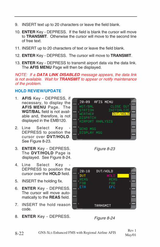
9. INSERT text up to 20 characters or leave the field blank.
10. ENTER Key - DEPRESS. If the field is blank the cursor will moveto TRANSMIT. Otherwise the cursor will move to the second lineof free text.
11. INSERT up to 20 characters of text or leave the field blank.
12. ENTER Key - DEPRESS. The cursor will move to TRANSMIT.
13. ENTER Key - DEPRESS to transmit airport data via the data link.The AFIS MENU Page will then be displayed.
NOTE: If a DATA LINK DISABLED message appears, the data linkis not available. Wait for TRANSMIT to appear or notify maintenanceof the problem.
HOLD REVIEW/UPDATE
1. AFIS Key - DEPRESS, ifnecessary, to display theAFIS MENU Page. TheWGT/BAL field is not avail-able and, therefore, is notdisplayed in the EMB120.
2. Line Select Key -DEPRESS to position thecursor over DVT/HOLD.See Figure 8-23.
3. ENTER Key - DEPRESS.The DVT/HOLD Page isdisplayed. See Figure 8-24.
4. Line Select Key -DEPRESS to position thecursor over the HOLD field.
5. INSERT the holding fix.
6. ENTER Key - DEPRESS.The cursor will move auto-matically to the REAS field.
7. INSERT the hold reasoncode.
8. ENTER Key - DEPRESS.
8-22 GNS-XLS Enhanced FMS with Regional Airline AFISRev 1
May/01
>
20:09 AFIS MENU
<
><
<
< >
WGT/BAL CLOSE OUT
STATION INITIALIZE
WEATHER DVT/HOLD
DISPATCH
AIRPORT ANALYSIS
SEND MSG
DISPLAY MSG<
Figure 8-23
>
< >
DVT HOLD
REAS REAS
FOB FOB
ETA EFC
TRANSMIT
20:18 DVT/HOLD
<
<
< >
>
>
< >
Figure 8-24
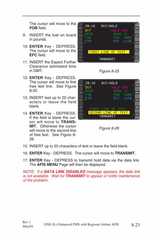
The cursor will move to theFOB field.
9. INSERT the fuel on boardin pounds.
10. ENTER Key - DEPRESS.The cursor will move to theEFC field.
11. INSERT the Expect FurtherClearance estimated timein GMT.
12. ENTER Key - DEPRESS.The cursor will move to firstfree text line. See Figure8-25.
13. INSERT text up to 20 char-acters or leave the fieldblank.
14. ENTER Key - DEPRESS.If the field is blank the cur-sor will move to TRANS-MIT. Otherwise the cursorwill move to the second lineof free text. See Figure 8-26.
15. INSERT up to 20 characters of text or leave the field blank.
16. ENTER Key - DEPRESS. The cursor will move to TRANSMIT.
17. ENTER Key - DEPRESS to transmit hold data via the data link.The AFIS MENU Page will then be displayed.
NOTE: If a DATA LINK DISABLED message appears, the data linkis not available. Wait for TRANSMIT to appear or notify maintenanceof the problem.
8-23GNS-XLS Enhanced FMS with Regional Airline AFISRev 1May/01
>
< >20:18 DVT/HOLD
<
<
< >
>
>
< >
DVT HOLD KDN
REAS REAS 12
FOB FOB 1000
ETA EFC 1120
FIRST LINE OF TEXT
TRANSMIT
Figure 8-25
>
< >20:18 DVT/HOLD
<
<
< >
>
>
< >
DVT HOLD KDN
REAS REAS 12
FOB FOB 1000
ETA EFC 1120
FIRST LINE OF TEXT
SECOND LINE OF TEXT
TRANSMIT
Figure 8-26
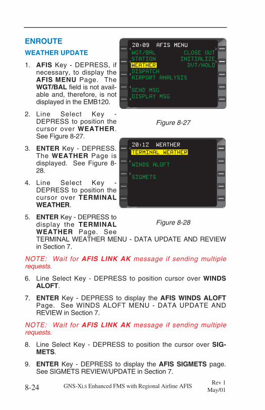
ENROUTEWEATHER UPDATE
1. AFIS Key - DEPRESS, ifnecessary, to display theAFIS MENU Page. TheWGT/BAL field is not avail-able and, therefore, is notdisplayed in the EMB120.
2. Line Select Key -DEPRESS to position thecursor over WEATHER.See Figure 8-27.
3. ENTER Key - DEPRESS.The WEATHER Page isdisplayed. See Figure 8-28.
4. Line Select Key -DEPRESS to position thecursor over TERMINALWEATHER.
5. ENTER Key - DEPRESS todisplay the TERMINALWEATHER Page. SeeTERMINAL WEATHER MENU - DATA UPDATE AND REVIEWin Section 7.
NOTE: Wait for AFIS LINK AK message if sending multiplerequests.
6. Line Select Key - DEPRESS to position cursor over WINDSALOFT.
7. ENTER Key - DEPRESS to display the AFIS WINDS ALOFTPage. See WINDS ALOFT MENU - DATA UPDATE ANDREVIEW in Section 7.
NOTE: Wait for AFIS LINK AK message if sending multiplerequests.
8. Line Select Key - DEPRESS to position the cursor over SIG-METS.
9. ENTER Key - DEPRESS to display the AFIS SIGMETS page.See SIGMETS REVIEW/UPDATE in Section 7.
8-24 GNS-XLS Enhanced FMS with Regional Airline AFISRev 1
May/01
< >
>
><
>
>
TERMINAL WEATHER
WINDS ALOFT
SIGMETS
20:12 WEATHER
<
<
<
Figure 8-28
>
20:09 AFIS MENU
<
><
<
< >
WGT/BAL CLOSE OUT
STATION INITIALIZE
WEATHER DVT/HOLD
DISPATCH
AIRPORT ANALYSIS
SEND MSG
DISPLAY MSG<
Figure 8-27
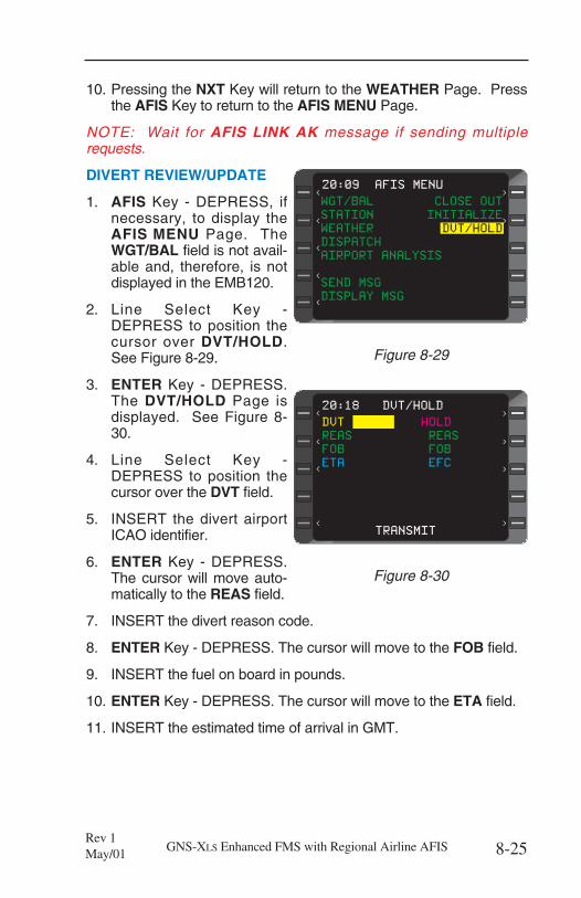
10. Pressing the NXT Key will return to the WEATHER Page. Pressthe AFIS Key to return to the AFIS MENU Page.
NOTE: Wait for AFIS LINK AK message if sending multiplerequests.
DIVERT REVIEW/UPDATE
1. AFIS Key - DEPRESS, ifnecessary, to display theAFIS MENU Page. TheWGT/BAL field is not avail-able and, therefore, is notdisplayed in the EMB120.
2. Line Select Key -DEPRESS to position thecursor over DVT/HOLD.See Figure 8-29.
3. ENTER Key - DEPRESS.The DVT/HOLD Page isdisplayed. See Figure 8-30.
4. Line Select Key -DEPRESS to position thecursor over the DVT field.
5. INSERT the divert airportICAO identifier.
6. ENTER Key - DEPRESS.The cursor will move auto-matically to the REAS field.
7. INSERT the divert reason code.
8. ENTER Key - DEPRESS. The cursor will move to the FOB field.
9. INSERT the fuel on board in pounds.
10. ENTER Key - DEPRESS. The cursor will move to the ETA field.
11. INSERT the estimated time of arrival in GMT.
8-25GNS-XLS Enhanced FMS with Regional Airline AFISRev 1May/01
>
20:09 AFIS MENU
<
><
<
< >
WGT/BAL CLOSE OUT
STATION INITIALIZE
WEATHER DVT/HOLD
DISPATCH
AIRPORT ANALYSIS
SEND MSG
DISPLAY MSG<
Figure 8-29
>
< >
DVT HOLD
REAS REAS
FOB FOB
ETA EFC
TRANSMIT
20:18 DVT/HOLD
<
<
< >
>
>
< >
Figure 8-30
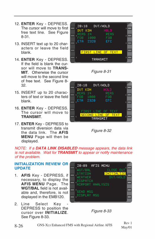
12. ENTER Key - DEPRESS.The cursor will move to firstfree text line. See Figure8-31.
13. INSERT text up to 20 char-acters or leave the fieldblank.
14. ENTER Key - DEPRESS.If the field is blank the cur-sor will move to TRANS-MIT. Otherwise the cursorwill move to the second lineof free text. See Figure 8-32.
15. INSERT up to 20 charac-ters of text or leave the fieldblank.
16. ENTER Key - DEPRESS.The cursor will move toTRANSMIT.
17. ENTER Key - DEPRESS totransmit diversion data viathe data link. The AFISMENU Page will then bedisplayed.
NOTE: If a DATA LINK DISABLED message appears, the data linkis not available. Wait for TRANSMIT to appear or notify maintenanceof the problem.
INITIALIZATION REVIEW ORUPDATE
1. AFIS Key - DEPRESS, ifnecessary, to display theAFIS MENU Page. TheWGT/BAL field is not avail-able and, therefore, is notdisplayed in the EMB120.
2. Line Select Key -DEPRESS to position thecursor over INITIALIZE.See Figure 8-33.
8-26 GNS-XLS Enhanced FMS with Regional Airline AFISRev 1
May/01
>
< >20:18 DVT/HOLD
<
<
< >
>
>
<
DVT KDN HOLD
REAS 14 REAS
FOB 1000 FOB
ETA 2320 EFC
FIRST LINE OF TEXT
SECOND LINE OF TEXT
TRANSMIT
>
Figure 8-32
>
20:09 AFIS MENU
<
><
<
< >
WGT/BAL CLOSE OUT
STATION INITIALIZE
WEATHER DVT/HOLD
DISPATCH
AIRPORT ANALYSIS
SEND MSG
DISPLAY MSG<
Figure 8-33
>
< >20:18 DVT/HOLD
<
<
< >
>
>
< >
DVT KDN HOLD
REAS 14 REAS
FOB 1000 FOB
ETA 2320 EFC
FIRST LINE OF TEXT
TRANSMIT
Figure 8-31
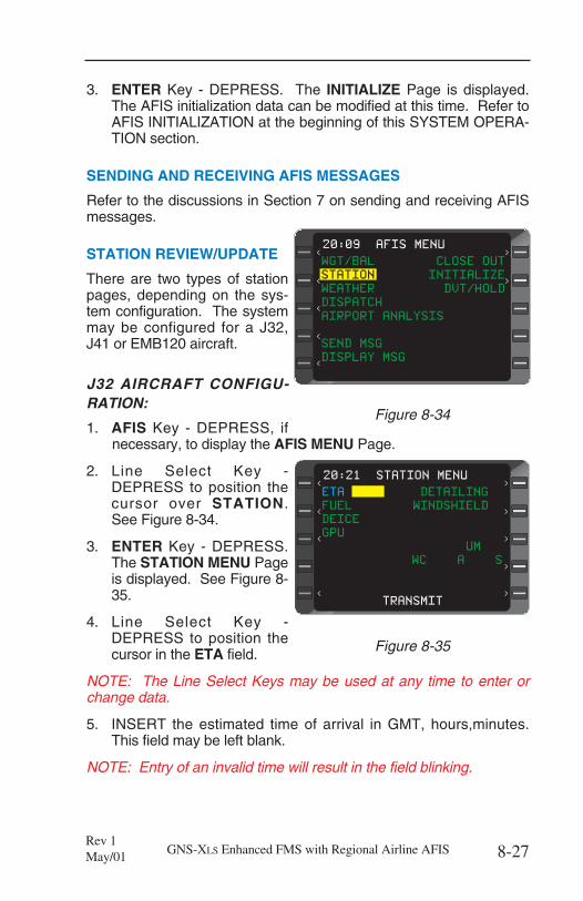
3. ENTER Key - DEPRESS. The INITIALIZE Page is displayed.The AFIS initialization data can be modified at this time. Refer toAFIS INITIALIZATION at the beginning of this SYSTEM OPERA-TION section.
SENDING AND RECEIVING AFIS MESSAGES
Refer to the discussions in Section 7 on sending and receiving AFISmessages.
STATION REVIEW/UPDATE
There are two types of stationpages, depending on the sys-tem configuration. The systemmay be configured for a J32,J41 or EMB120 aircraft.
J32 AIRCRAFT CONFIGU-RATION:
1. AFIS Key - DEPRESS, ifnecessary, to display the AFIS MENU Page.
2. Line Select Key -DEPRESS to position thecursor over STATION.See Figure 8-34.
3. ENTER Key - DEPRESS.The STATION MENU Pageis displayed. See Figure 8-35.
4. Line Select Key -DEPRESS to position thecursor in the ETA field.
NOTE: The Line Select Keys may be used at any time to enter orchange data.
5. INSERT the estimated time of arrival in GMT, hours,minutes.This field may be left blank.
NOTE: Entry of an invalid time will result in the field blinking.
8-27GNS-XLS Enhanced FMS with Regional Airline AFISRev 1May/01
>
20:09 AFIS MENU
<
><
<
< >
WGT/BAL CLOSE OUT
STATION INITIALIZE
WEATHER DVT/HOLD
DISPATCH
AIRPORT ANALYSIS
SEND MSG
DISPLAY MSG<
Figure 8-34
20:21 STATION MENU
><
<
< >
<
>
>
>
ETA DETAILING
FUEL WINDSHIELD
DEICE
GPU
UM
s WC A S
TRANSMIT
Figure 8-35
6. ENTER Key - DEPRESS. The cursor will automatically move tothe FUEL field.
7. INSERT a Y for yes if fueling will be needed. Insert an N for no iffueling will not be needed.
8. ENTER Key - DEPRESS. The cursor will move to the DEICEfield.
9. INSERT a Y for yes if deicing will be needed. Insert an N for no ifdeicing will not be needed.
10. ENTER Key - DEPRESS. The cursor will move to the GPU field.
11. INSERT a Y for yes if a ground power unit will be needed. Insertan N for no if a ground power unit will not be needed.
12. ENTER Key - DEPRESS. The cursor will move to the DETAIL-ING field
13. INSERT a Y for yes if detailing service will be needed. Insert anN for no if detailing service will not be needed.
14. ENTER Key - DEPRESS. The cursor will move to the WIND-SHIELD field.
15. INSERT a Y for yes if windshield service will be needed. Insertan N for no if windshield service will not be needed.
16. ENTER Key - DEPRESS. The cursor will move to the UM field.
17. INSERT the number of unaccompanied minors on board.
18. ENTER Key - DEPRESS. The cursor will move to the first WCfield. This first field is for aisle type (A) wheel chair.
19. INSERT the number of passengers on board needing aisle typewheel chairs.
20. ENTER Key - DEPRESS. The cursor will move to the secondWC field. This second field is for standard type (S) wheel chair.
21. INSERT the number of passengers on board needing standardtype wheel chairs.
8-28 GNS-XLS Enhanced FMS with Regional Airline AFISRev 1
May/01
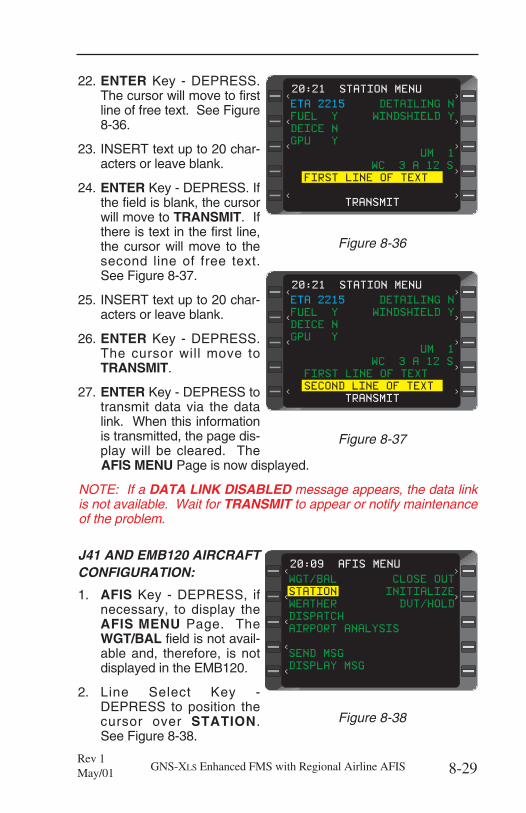
22. ENTER Key - DEPRESS.The cursor will move to firstline of free text. See Figure8-36.
23. INSERT text up to 20 char-acters or leave blank.
24. ENTER Key - DEPRESS. Ifthe field is blank, the cursorwill move to TRANSMIT. Ifthere is text in the first line,the cursor will move to thesecond line of free text.See Figure 8-37.
25. INSERT text up to 20 char-acters or leave blank.
26. ENTER Key - DEPRESS.The cursor will move toTRANSMIT.
27. ENTER Key - DEPRESS totransmit data via the datalink. When this informationis transmitted, the page dis-play will be cleared. TheAFIS MENU Page is now displayed.
NOTE: If a DATA LINK DISABLED message appears, the data linkis not available. Wait for TRANSMIT to appear or notify maintenanceof the problem.
J41 AND EMB120 AIRCRAFTCONFIGURATION:
1. AFIS Key - DEPRESS, ifnecessary, to display theAFIS MENU Page. TheWGT/BAL field is not avail-able and, therefore, is notdisplayed in the EMB120.
2. Line Select Key -DEPRESS to position thecursor over STATION.See Figure 8-38.
8-29GNS-XLS Enhanced FMS with Regional Airline AFISRev 1May/01
20:21 STATION MENU
><
<
< >
<
>
>
>
ETA 2215 DETAILING N
FUEL Y WINDSHIELD Y
DEICE N
GPU Y
UM 1
s WC 3 A 12 S
FIRST LINE OF TEXT
TRANSMIT
Figure 8-36
20:21 STATION MENU
><
<
< >
<
>
>
>
ETA 2215 DETAILING N
FUEL Y WINDSHIELD Y
DEICE N
GPU Y
UM 1
s WC 3 A 12 S
FIRST LINE OF TEXT
SECOND LINE OF TEXT
TRANSMIT
Figure 8-37
>
20:09 AFIS MENU
<
><
<
< >
WGT/BAL CLOSE OUT
STATION INITIALIZE
WEATHER DVT/HOLD
DISPATCH
AIRPORT ANALYSIS
SEND MSG
DISPLAY MSG<
Figure 8-38
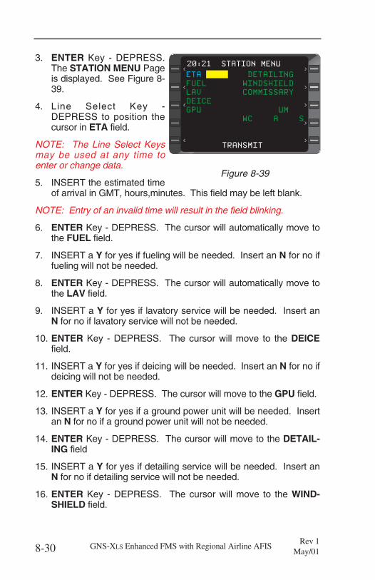
3. ENTER Key - DEPRESS.The STATION MENU Pageis displayed. See Figure 8-39.
4. Line Select Key -DEPRESS to position thecursor in ETA field.
NOTE: The Line Select Keysmay be used at any time toenter or change data.
5. INSERT the estimated timeof arrival in GMT, hours,minutes. This field may be left blank.
NOTE: Entry of an invalid time will result in the field blinking.
6. ENTER Key - DEPRESS. The cursor will automatically move tothe FUEL field.
7. INSERT a Y for yes if fueling will be needed. Insert an N for no iffueling will not be needed.
8. ENTER Key - DEPRESS. The cursor will automatically move tothe LAV field.
9. INSERT a Y for yes if lavatory service will be needed. Insert anN for no if lavatory service will not be needed.
10. ENTER Key - DEPRESS. The cursor will move to the DEICEfield.
11. INSERT a Y for yes if deicing will be needed. Insert an N for no ifdeicing will not be needed.
12. ENTER Key - DEPRESS. The cursor will move to the GPU field.
13. INSERT a Y for yes if a ground power unit will be needed. Insertan N for no if a ground power unit will not be needed.
14. ENTER Key - DEPRESS. The cursor will move to the DETAIL-ING field
15. INSERT a Y for yes if detailing service will be needed. Insert anN for no if detailing service will not be needed.
16. ENTER Key - DEPRESS. The cursor will move to the WIND-SHIELD field.
8-30 GNS-XLS Enhanced FMS with Regional Airline AFISRev 1
May/01
20:21 STATION MENU
><
<
< >
<
>
>
>
ETA DETAILING
FUEL WINDSHIELD
LAV COMMISSARY
DEICE
GPU UM
WC A S
TRANSMIT
Figure 8-39
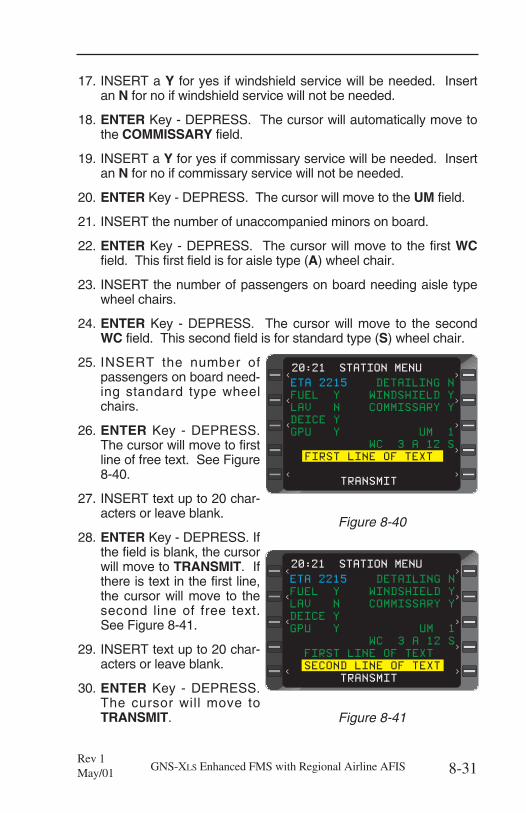
17. INSERT a Y for yes if windshield service will be needed. Insertan N for no if windshield service will not be needed.
18. ENTER Key - DEPRESS. The cursor will automatically move tothe COMMISSARY field.
19. INSERT a Y for yes if commissary service will be needed. Insertan N for no if commissary service will not be needed.
20. ENTER Key - DEPRESS. The cursor will move to the UM field.
21. INSERT the number of unaccompanied minors on board.
22. ENTER Key - DEPRESS. The cursor will move to the first WCfield. This first field is for aisle type (A) wheel chair.
23. INSERT the number of passengers on board needing aisle typewheel chairs.
24. ENTER Key - DEPRESS. The cursor will move to the secondWC field. This second field is for standard type (S) wheel chair.
25. INSERT the number ofpassengers on board need-ing standard type wheelchairs.
26. ENTER Key - DEPRESS.The cursor will move to firstline of free text. See Figure8-40.
27. INSERT text up to 20 char-acters or leave blank.
28. ENTER Key - DEPRESS. Ifthe field is blank, the cursorwill move to TRANSMIT. Ifthere is text in the first line,the cursor will move to thesecond line of free text.See Figure 8-41.
29. INSERT text up to 20 char-acters or leave blank.
30. ENTER Key - DEPRESS.The cursor will move toTRANSMIT.
8-31GNS-XLS Enhanced FMS with Regional Airline AFISRev 1May/01
20:21 STATION MENU
><
<
< >
<
>
>
>
ETA 2215 DETAILING N
FUEL Y WINDSHIELD Y
LAV N COMMISSARY Y
DEICE Y
GPU Y UM 1
WC 3 A 12 S
FIRST LINE OF TEXT
TRANSMIT
Figure 8-40
20:21 STATION MENU
><
<
< >
<
>
>
>
ETA 2215 DETAILING N
FUEL Y WINDSHIELD Y
LAV N COMMISSARY Y
DEICE Y
GPU Y UM 1
WC 3 A 12 S
FIRST LINE OF TEXT
SECOND LINE OF TEXT
TRANSMIT
Figure 8-41
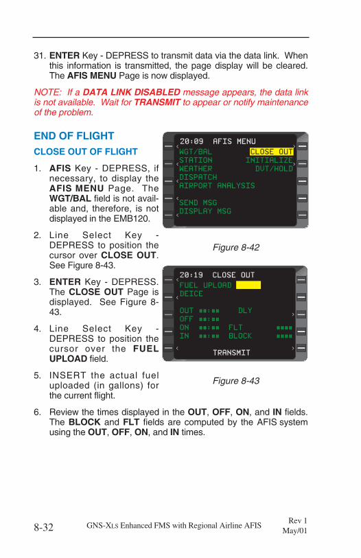
31. ENTER Key - DEPRESS to transmit data via the data link. Whenthis information is transmitted, the page display will be cleared.The AFIS MENU Page is now displayed.
NOTE: If a DATA LINK DISABLED message appears, the data linkis not available. Wait for TRANSMIT to appear or notify maintenanceof the problem.
END OF FLIGHTCLOSE OUT OF FLIGHT
1. AFIS Key - DEPRESS, ifnecessary, to display theAFIS MENU Page. TheWGT/BAL field is not avail-able and, therefore, is notdisplayed in the EMB120.
2. Line Select Key -DEPRESS to position thecursor over CLOSE OUT.See Figure 8-43.
3. ENTER Key - DEPRESS.The CLOSE OUT Page isdisplayed. See Figure 8-43.
4. Line Select Key -DEPRESS to position thecursor over the FUELUPLOAD field.
5. INSERT the actual fueluploaded (in gallons) forthe current flight.
6. Review the times displayed in the OUT, OFF, ON, and IN fields.The BLOCK and FLT fields are computed by the AFIS systemusing the OUT, OFF, ON, and IN times.
8-32 GNS-XLS Enhanced FMS with Regional Airline AFISRev 1
May/01
>
20:09 AFIS MENU
<
><
<
< >
<
WGT/BAL CLOSE OUT
STATION INITIALIZE
WEATHER DVT/HOLD
DISPATCH
AIRPORT ANALYSIS
SEND MSG
DISPLAY MSG
Figure 8-42
>
><
>
<
< >20:19 CLOSE OUT
<
< >
<
>
FUEL UPLOAD
DEICE
OUT ##:## DLY
OFF ##:##
ON ##:## FLT ####
IN ##:## BLOCK ####
TRANSMIT
Figure 8-43
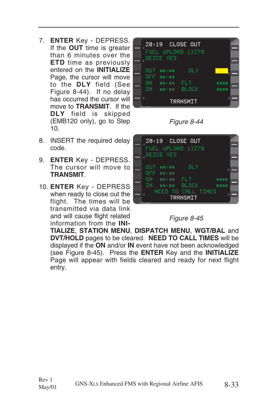
7. ENTER Key - DEPRESS.If the OUT time is greaterthan 6 minutes over theETD time as previouslyentered on the INITIALIZEPage, the cursor will moveto the DLY field (SeeFigure 8-44). If no delayhas occurred the cursor willmove to TRANSMIT. If theDLY field is skipped(EMB120 only), go to Step10.
8. INSERT the required delaycode.
9. ENTER Key - DEPRESS.The cursor will move toTRANSMIT.
10. ENTER Key - DEPRESSwhen ready to close out theflight. The times will betransmitted via data linkand will cause flight relatedinformation from the INI-TIALIZE, STATION MENU, DISPATCH MENU, WGT/BAL andDVT/HOLD pages to be cleared. NEED TO CALL TIMES will bedisplayed if the ON and/or IN event have not been acknowledged(see Figure 8-45). Press the ENTER Key and the INITIALIZEPage will appear with fields cleared and ready for next flightentry.
8-33GNS-XLS Enhanced FMS with Regional Airline AFISRev 1May/01
>
><
>
<
< >
FUEL UPLOAD 11270
DEICE YES
OUT ##:## DLY
OFF ##:##
ON ##:## FLT ####
IN ##:## BLOCK ####
TRANSMIT
20:19 CLOSE OUT
<
< >
<
>
Figure 8-44
>
><
>
<
< >
FUEL UPLOAD 11270
DEICE YES
OUT ##:## DLY
OFF ##:##
ON ##:## FLT ####
IN ##:## BLOCK ####
NEED TO CALL TIMES
TRANSMIT
20:19 CLOSE OUT
<
< >
<
>
Figure 8-45

This Page Intentionally Left Blank
8-34 GNS-XLS Enhanced FMS with Regional Airline AFISRev 1
May/01
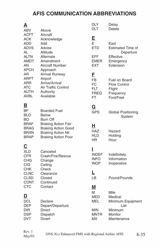
AABV AboveACFT AircraftACK AcknowledgeADD AddADVS AdviseAL AltitudeALTN AlternateAMDT AmendmentAN Aircraft NumberAPCH ApproachAR Arrival RunwayARPT AirportARR Arrive/ArrivalATC Air Traffic ControlAUTH AuthorityAVBL Available
BBF Boarded FuelBLO BelowBO Burn OffBRAF Braking Action FairBRAG Braking Action GoodBRAN Braking Action NilBRAP Braking Action Poor
CXLD CanceledCFR Crash/Fire/RescueCHG ChangeCIG CeilingCHK CheckCLNC ClearanceCLSD ClosedCONT ContinuedCTC Contact
DDCL DeclareDEP Depart/DepartureDIR DirectDSP DispatchDVT Divert
DLY DelayDLT Delete
EE EastETD Estimated Time of
DepartureEFF EffectiveEMER EmergencyEXT Extension
FFB Fuel on BoardFC Flow ControlFLT FlightFREQ FrequencyFT Foot/Feet
GGPS Global Positioning
System
HHAZ HazardHLD HoldingHR Hour
IINDEF IndefinitelyINFO InformationINOP Inoperative
LLB Pound/Pounds
MM MileMED MedicalMEL Minimum Equipment
ListMIN MinimumMNTR MonitorMX Maintenance
8-35GNS-XLS Enhanced FMS with Regional Airline AFISRev. 1May/01
AFIS COMMUNICATION ABBREVIATIONS
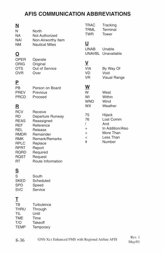
NN NorthNA Not AuthorizedNAI Non-Airworthy ItemNM Nautical Miles
OOPER OperateORIG OriginalOTS Out of ServiceOVR Over
PPB Person on BoardPREV PreviousPRCD Proceed
RRCV ReceiveRD Departure RunwayREAS ReassignedREF ReferenceREL ReleaseRMDR RemainderRMK Remark/RemarksRPLC ReplaceRPRT ReportRQRD RequiredRQST RequestRT Route Information
SS SouthSKED ScheduledSPD SpeedSVC Service
TTB TurbulenceTHRU ThroughTIL UntilTME TimeT/O TakeoffTEMP Temporary
TRAC TrackingTRML TerminalTWR Tower
UUNAB UnableUNAVBL Unavailable
VVIA By Way OfVD VoidVR Visual Range
WW WestWI WithinWND WindWX Weather
75 Hijack76 Lost Comm/ And+ In Addition/Also> More Than< Less Than# Number
8-36 GNS-XLS Enhanced FMS with Regional Airline AFISRev. 1
May/01
AFIS COMMUNICATION ABBREVIATIONS
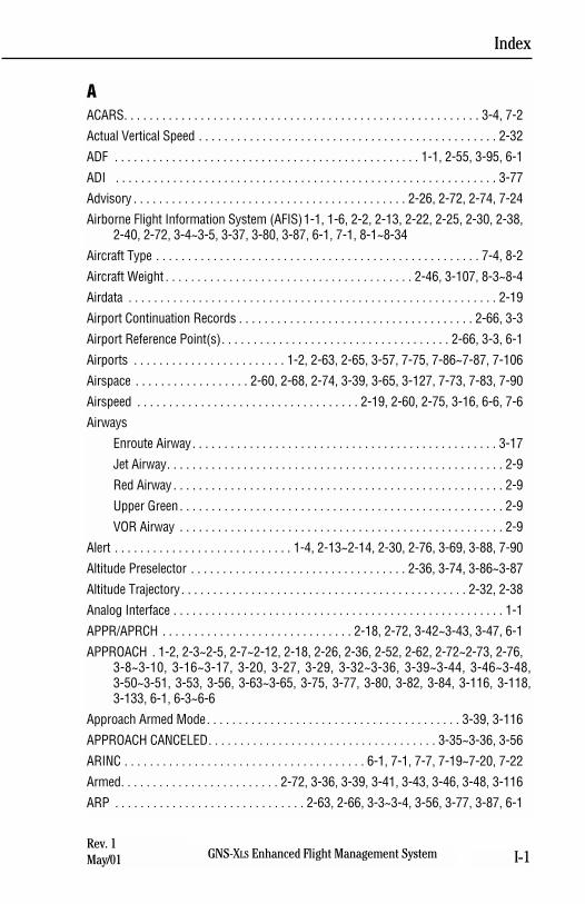
AACARS. . . . . . . . . . . . . . . . . . . . . . . . . . . . . . . . . . . . . . . . . . . . . . . . . . . . . . . . 3-4, 7-2
Actual Vertical Speed . . . . . . . . . . . . . . . . . . . . . . . . . . . . . . . . . . . . . . . . . . . . . . . 2-32
ADF . . . . . . . . . . . . . . . . . . . . . . . . . . . . . . . . . . . . . . . . . . . . . . . . 1-1, 2-55, 3-95, 6-1
ADI . . . . . . . . . . . . . . . . . . . . . . . . . . . . . . . . . . . . . . . . . . . . . . . . . . . . . . . . . . . . 3-77
Advisory . . . . . . . . . . . . . . . . . . . . . . . . . . . . . . . . . . . . . . . . . . . 2-26, 2-72, 2-74, 7-24
Airborne Flight Information System (AFIS)1-1, 1-6, 2-2, 2-13, 2-22, 2-25, 2-30, 2-38,2-40, 2-72, 3-4~3-5, 3-37, 3-80, 3-87, 6-1, 7-1, 8-1~8-34
Aircraft Type . . . . . . . . . . . . . . . . . . . . . . . . . . . . . . . . . . . . . . . . . . . . . . . . . . . 7-4, 8-2
Aircraft Weight . . . . . . . . . . . . . . . . . . . . . . . . . . . . . . . . . . . . . . . 2-46, 3-107, 8-3~8-4
Airdata . . . . . . . . . . . . . . . . . . . . . . . . . . . . . . . . . . . . . . . . . . . . . . . . . . . . . . . . . . 2-19
Airport Continuation Records . . . . . . . . . . . . . . . . . . . . . . . . . . . . . . . . . . . . . 2-66, 3-3
Airport Reference Point(s). . . . . . . . . . . . . . . . . . . . . . . . . . . . . . . . . . . . 2-66, 3-3, 6-1
Airports . . . . . . . . . . . . . . . . . . . . . . . . 1-2, 2-63, 2-65, 3-57, 7-75, 7-86~7-87, 7-106
Airspace . . . . . . . . . . . . . . . . . . 2-60, 2-68, 2-74, 3-39, 3-65, 3-127, 7-73, 7-83, 7-90
Airspeed . . . . . . . . . . . . . . . . . . . . . . . . . . . . . . . . . . . 2-19, 2-60, 2-75, 3-16, 6-6, 7-6
Airways
Enroute Airway. . . . . . . . . . . . . . . . . . . . . . . . . . . . . . . . . . . . . . . . . . . . . . . . 3-17
Jet Airway. . . . . . . . . . . . . . . . . . . . . . . . . . . . . . . . . . . . . . . . . . . . . . . . . . . . . 2-9
Red Airway . . . . . . . . . . . . . . . . . . . . . . . . . . . . . . . . . . . . . . . . . . . . . . . . . . . . 2-9
Upper Green . . . . . . . . . . . . . . . . . . . . . . . . . . . . . . . . . . . . . . . . . . . . . . . . . . . 2-9
VOR Airway . . . . . . . . . . . . . . . . . . . . . . . . . . . . . . . . . . . . . . . . . . . . . . . . . . . 2-9
Alert . . . . . . . . . . . . . . . . . . . . . . . . . . . . 1-4, 2-13~2-14, 2-30, 2-76, 3-69, 3-88, 7-90
Altitude Preselector . . . . . . . . . . . . . . . . . . . . . . . . . . . . . . . . . . 2-36, 3-74, 3-86~3-87
Altitude Trajectory. . . . . . . . . . . . . . . . . . . . . . . . . . . . . . . . . . . . . . . . . . . . . 2-32, 2-38
Analog Interface . . . . . . . . . . . . . . . . . . . . . . . . . . . . . . . . . . . . . . . . . . . . . . . . . . . . 1-1
APPR/APRCH . . . . . . . . . . . . . . . . . . . . . . . . . . . . . . 2-18, 2-72, 3-42~3-43, 3-47, 6-1
APPROACH . 1-2, 2-3~2-5, 2-7~2-12, 2-18, 2-26, 2-36, 2-52, 2-62, 2-72~2-73, 2-76,3-8~3-10, 3-16~3-17, 3-20, 3-27, 3-29, 3-32~3-36, 3-39~3-44, 3-46~3-48,3-50~3-51, 3-53, 3-56, 3-63~3-65, 3-75, 3-77, 3-80, 3-82, 3-84, 3-116, 3-118,3-133, 6-1, 6-3~6-6
Approach Armed Mode. . . . . . . . . . . . . . . . . . . . . . . . . . . . . . . . . . . . . . . . 3-39, 3-116
APPROACH CANCELED. . . . . . . . . . . . . . . . . . . . . . . . . . . . . . . . . . . . 3-35~3-36, 3-56
ARINC . . . . . . . . . . . . . . . . . . . . . . . . . . . . . . . . . . . . . . 6-1, 7-1, 7-7, 7-19~7-20, 7-22
Armed. . . . . . . . . . . . . . . . . . . . . . . . . 2-72, 3-36, 3-39, 3-41, 3-43, 3-46, 3-48, 3-116
ARP . . . . . . . . . . . . . . . . . . . . . . . . . . . . . . 2-63, 2-66, 3-3~3-4, 3-56, 3-77, 3-87, 6-1
Index
GNS-XLS Enhanced Flight Management System I-1Rev. 1May/01
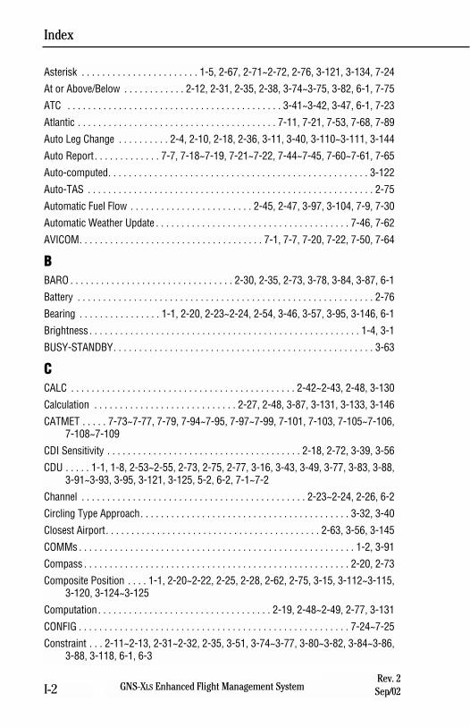
Index
GNS-XLS Enhanced Flight Management SystemI-2Rev. 2Sep/02
Asterisk . . . . . . . . . . . . . . . . . . . . . . . 1-5, 2-67, 2-71~2-72, 2-76, 3-121, 3-134, 7-24
At or Above/Below . . . . . . . . . . . . 2-12, 2-31, 2-35, 2-38, 3-74~3-75, 3-82, 6-1, 7-75
ATC . . . . . . . . . . . . . . . . . . . . . . . . . . . . . . . . . . . . . . . . . . 3-41~3-42, 3-47, 6-1, 7-23
Atlantic . . . . . . . . . . . . . . . . . . . . . . . . . . . . . . . . . . . . . . . 7-11, 7-21, 7-53, 7-68, 7-89
Auto Leg Change . . . . . . . . . . 2-4, 2-10, 2-18, 2-36, 3-11, 3-40, 3-110~3-111, 3-144
Auto Report. . . . . . . . . . . . . 7-7, 7-18~7-19, 7-21~7-22, 7-44~7-45, 7-60~7-61, 7-65
Auto-computed. . . . . . . . . . . . . . . . . . . . . . . . . . . . . . . . . . . . . . . . . . . . . . . . . . . 3-122
Auto-TAS . . . . . . . . . . . . . . . . . . . . . . . . . . . . . . . . . . . . . . . . . . . . . . . . . . . . . . . . 2-75
Automatic Fuel Flow . . . . . . . . . . . . . . . . . . . . . . . . 2-45, 2-47, 3-97, 3-104, 7-9, 7-30
Automatic Weather Update . . . . . . . . . . . . . . . . . . . . . . . . . . . . . . . . . . . . . . 7-46, 7-62
AVICOM. . . . . . . . . . . . . . . . . . . . . . . . . . . . . . . . . . . . 7-1, 7-7, 7-20, 7-22, 7-50, 7-64
BBARO . . . . . . . . . . . . . . . . . . . . . . . . . . . . . . . . 2-30, 2-35, 2-73, 3-78, 3-84, 3-87, 6-1
Battery . . . . . . . . . . . . . . . . . . . . . . . . . . . . . . . . . . . . . . . . . . . . . . . . . . . . . . . . . . 2-76
Bearing . . . . . . . . . . . . . . . . 1-1, 2-20, 2-23~2-24, 2-54, 3-46, 3-57, 3-95, 3-146, 6-1
Brightness . . . . . . . . . . . . . . . . . . . . . . . . . . . . . . . . . . . . . . . . . . . . . . . . . . . . . 1-4, 3-1
BUSY-STANDBY. . . . . . . . . . . . . . . . . . . . . . . . . . . . . . . . . . . . . . . . . . . . . . . . . . . 3-63
CCALC . . . . . . . . . . . . . . . . . . . . . . . . . . . . . . . . . . . . . . . . . . . . 2-42~2-43, 2-48, 3-130
Calculation . . . . . . . . . . . . . . . . . . . . . . . . . . . . 2-27, 2-48, 3-87, 3-131, 3-133, 3-146
CATMET . . . . . 7-73~7-77, 7-79, 7-94~7-95, 7-97~7-99, 7-101, 7-103, 7-105~7-106,7-108~7-109
CDI Sensitivity . . . . . . . . . . . . . . . . . . . . . . . . . . . . . . . . . . . . . . 2-18, 2-72, 3-39, 3-56
CDU . . . . . 1-1, 1-8, 2-53~2-55, 2-73, 2-75, 2-77, 3-16, 3-43, 3-49, 3-77, 3-83, 3-88,3-91~3-93, 3-95, 3-121, 3-125, 5-2, 6-2, 7-1~7-2
Channel . . . . . . . . . . . . . . . . . . . . . . . . . . . . . . . . . . . . . . . . . . . . 2-23~2-24, 2-26, 6-2
Circling Type Approach. . . . . . . . . . . . . . . . . . . . . . . . . . . . . . . . . . . . . . . . . 3-32, 3-40
Closest Airport. . . . . . . . . . . . . . . . . . . . . . . . . . . . . . . . . . . . . . . . . . 2-63, 3-56, 3-145
COMMs . . . . . . . . . . . . . . . . . . . . . . . . . . . . . . . . . . . . . . . . . . . . . . . . . . . . . . 1-2, 3-91
Compass . . . . . . . . . . . . . . . . . . . . . . . . . . . . . . . . . . . . . . . . . . . . . . . . . . . . 2-20, 2-73
Composite Position . . . . 1-1, 2-20~2-22, 2-25, 2-28, 2-62, 2-75, 3-15, 3-112~3-115,3-120, 3-124~3-125
Computation . . . . . . . . . . . . . . . . . . . . . . . . . . . . . . . . . . 2-19, 2-48~2-49, 2-77, 3-131
CONFIG . . . . . . . . . . . . . . . . . . . . . . . . . . . . . . . . . . . . . . . . . . . . . . . . . . . . . 7-24~7-25
Constraint . . . 2-11~2-13, 2-31~2-32, 2-35, 3-51, 3-74~3-77, 3-80~3-82, 3-84~3-86,3-88, 3-118, 6-1, 6-3
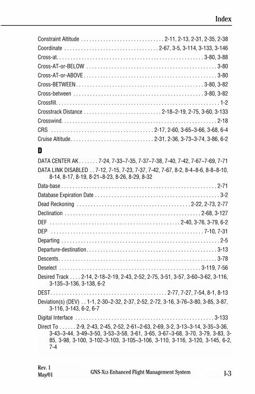
Constraint Altitude . . . . . . . . . . . . . . . . . . . . . . . . . . . . . . 2-11, 2-13, 2-31, 2-35, 2-38
Coordinate . . . . . . . . . . . . . . . . . . . . . . . . . . . . . . . . . . 2-67, 3-5, 3-114, 3-133, 3-146
Cross-at. . . . . . . . . . . . . . . . . . . . . . . . . . . . . . . . . . . . . . . . . . . . . . . . . . . . . 3-80, 3-88
Cross-AT-or-BELOW . . . . . . . . . . . . . . . . . . . . . . . . . . . . . . . . . . . . . . . . . . . . . . . 3-80
Cross-AT-or-ABOVE . . . . . . . . . . . . . . . . . . . . . . . . . . . . . . . . . . . . . . . . . . . . . . . . 3-80
Cross-BETWEEN . . . . . . . . . . . . . . . . . . . . . . . . . . . . . . . . . . . . . . . . . . . . . . 3-80, 3-82
Cross-between . . . . . . . . . . . . . . . . . . . . . . . . . . . . . . . . . . . . . . . . . . . . . . . 3-80, 3-82
Crossfill. . . . . . . . . . . . . . . . . . . . . . . . . . . . . . . . . . . . . . . . . . . . . . . . . . . . . . . . . . . 1-2
Crosstrack Distance . . . . . . . . . . . . . . . . . . . . . . . . . . . . 2-18~2-19, 2-75, 3-60, 3-133
Crosswind. . . . . . . . . . . . . . . . . . . . . . . . . . . . . . . . . . . . . . . . . . . . . . . . . . . . . . . . 2-18
CRS . . . . . . . . . . . . . . . . . . . . . . . . . . . . . . . . . . . . . 2-17, 2-60, 3-65~3-66, 3-68, 6-4
Cruise Altitude. . . . . . . . . . . . . . . . . . . . . . . . . . . . . . 2-31, 2-36, 3-73~3-74, 3-86, 6-2
DDATA CENTER AK . . . . . . . 7-24, 7-33~7-35, 7-37~7-38, 7-40, 7-42, 7-67~7-69, 7-71
DATA LINK DISABLED . . 7-12, 7-15, 7-23, 7-37, 7-42, 7-67, 8-2, 8-4~8-6, 8-8~8-10,8-14, 8-17, 8-19, 8-21~8-23, 8-26, 8-29, 8-32
Data-base . . . . . . . . . . . . . . . . . . . . . . . . . . . . . . . . . . . . . . . . . . . . . . . . . . . . . . . . 2-71
Database Expiration Date . . . . . . . . . . . . . . . . . . . . . . . . . . . . . . . . . . . . . . . . . . . . . 3-2
Dead Reckoning . . . . . . . . . . . . . . . . . . . . . . . . . . . . . . . . . . . . . . . . . 2-22, 2-73, 2-77
Declination . . . . . . . . . . . . . . . . . . . . . . . . . . . . . . . . . . . . . . . . . . . . . . . . . 2-68, 3-127
DEF . . . . . . . . . . . . . . . . . . . . . . . . . . . . . . . . . . . . . . . . . . . . . . . 2-40, 3-76, 3-79, 6-2
DEP . . . . . . . . . . . . . . . . . . . . . . . . . . . . . . . . . . . . . . . . . . . . . . . . . . . . . . . 7-10, 7-31
Departing . . . . . . . . . . . . . . . . . . . . . . . . . . . . . . . . . . . . . . . . . . . . . . . . . . . . . . . . . 2-5
Departure-destination. . . . . . . . . . . . . . . . . . . . . . . . . . . . . . . . . . . . . . . . . . . . . . . 3-13
Descents. . . . . . . . . . . . . . . . . . . . . . . . . . . . . . . . . . . . . . . . . . . . . . . . . . . . . . . . . 3-78
Deselect . . . . . . . . . . . . . . . . . . . . . . . . . . . . . . . . . . . . . . . . . . . . . . . . . . . 3-119, 7-56
Desired Track . . . . 2-14, 2-18~2-19, 2-43, 2-52, 2-75, 3-51, 3-57, 3-60~3-62, 3-116,3-135~3-136, 3-138, 6-2
DEST. . . . . . . . . . . . . . . . . . . . . . . . . . . . . . . . . . . . . . . . . . 2-77, 7-27, 7-54, 8-1, 8-13
Deviation(s) (DEV) . . 1-1, 2-30~2-32, 2-37, 2-52, 2-72, 3-16, 3-76~3-80, 3-85, 3-87,3-116, 3-143, 6-2, 6-7
Digital Interface . . . . . . . . . . . . . . . . . . . . . . . . . . . . . . . . . . . . . . . . . . . . . . . . . . 3-133
Direct To . . . . . . 2-9, 2-43, 2-45, 2-52, 2-61~2-63, 2-69, 3-2, 3-13~3-14, 3-35~3-36,3-43~3-44, 3-49~3-50, 3-53~3-58, 3-61, 3-65, 3-67~3-68, 3-70, 3-79, 3-83, 3-85, 3-98, 3-100, 3-102~3-103, 3-105~3-106, 3-110, 3-116, 3-120, 3-145, 6-2,7-4
Index
GNS-XLS Enhanced Flight Management System I-3Rev. 1May/01
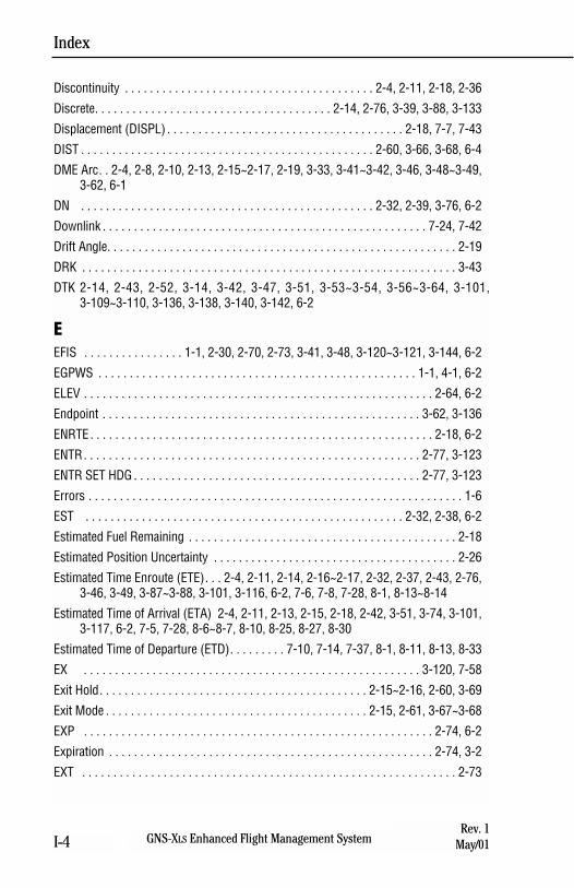
Discontinuity . . . . . . . . . . . . . . . . . . . . . . . . . . . . . . . . . . . . . . . . 2-4, 2-11, 2-18, 2-36
Discrete. . . . . . . . . . . . . . . . . . . . . . . . . . . . . . . . . . . . . . 2-14, 2-76, 3-39, 3-88, 3-133
Displacement (DISPL) . . . . . . . . . . . . . . . . . . . . . . . . . . . . . . . . . . . . . . 2-18, 7-7, 7-43
DIST . . . . . . . . . . . . . . . . . . . . . . . . . . . . . . . . . . . . . . . . . . . . . . . 2-60, 3-66, 3-68, 6-4
DME Arc. . 2-4, 2-8, 2-10, 2-13, 2-15~2-17, 2-19, 3-33, 3-41~3-42, 3-46, 3-48~3-49,3-62, 6-1
DN . . . . . . . . . . . . . . . . . . . . . . . . . . . . . . . . . . . . . . . . . . . . . . . 2-32, 2-39, 3-76, 6-2
Downlink . . . . . . . . . . . . . . . . . . . . . . . . . . . . . . . . . . . . . . . . . . . . . . . . . . . . 7-24, 7-42
Drift Angle. . . . . . . . . . . . . . . . . . . . . . . . . . . . . . . . . . . . . . . . . . . . . . . . . . . . . . . . 2-19
DRK . . . . . . . . . . . . . . . . . . . . . . . . . . . . . . . . . . . . . . . . . . . . . . . . . . . . . . . . . . . . 3-43
DTK 2-14, 2-43, 2-52, 3-14, 3-42, 3-47, 3-51, 3-53~3-54, 3-56~3-64, 3-101,3-109~3-110, 3-136, 3-138, 3-140, 3-142, 6-2
EEFIS . . . . . . . . . . . . . . . . 1-1, 2-30, 2-70, 2-73, 3-41, 3-48, 3-120~3-121, 3-144, 6-2
EGPWS . . . . . . . . . . . . . . . . . . . . . . . . . . . . . . . . . . . . . . . . . . . . . . . . . . . 1-1, 4-1, 6-2
ELEV . . . . . . . . . . . . . . . . . . . . . . . . . . . . . . . . . . . . . . . . . . . . . . . . . . . . . . . . 2-64, 6-2
Endpoint . . . . . . . . . . . . . . . . . . . . . . . . . . . . . . . . . . . . . . . . . . . . . . . . . . . 3-62, 3-136
ENRTE. . . . . . . . . . . . . . . . . . . . . . . . . . . . . . . . . . . . . . . . . . . . . . . . . . . . . . . 2-18, 6-2
ENTR. . . . . . . . . . . . . . . . . . . . . . . . . . . . . . . . . . . . . . . . . . . . . . . . . . . . . . 2-77, 3-123
ENTR SET HDG . . . . . . . . . . . . . . . . . . . . . . . . . . . . . . . . . . . . . . . . . . . . . . 2-77, 3-123
Errors . . . . . . . . . . . . . . . . . . . . . . . . . . . . . . . . . . . . . . . . . . . . . . . . . . . . . . . . . . . . 1-6
EST . . . . . . . . . . . . . . . . . . . . . . . . . . . . . . . . . . . . . . . . . . . . . . . . . . . 2-32, 2-38, 6-2
Estimated Fuel Remaining . . . . . . . . . . . . . . . . . . . . . . . . . . . . . . . . . . . . . . . . . . . 2-18
Estimated Position Uncertainty . . . . . . . . . . . . . . . . . . . . . . . . . . . . . . . . . . . . . . . 2-26
Estimated Time Enroute (ETE). . . 2-4, 2-11, 2-14, 2-16~2-17, 2-32, 2-37, 2-43, 2-76,3-46, 3-49, 3-87~3-88, 3-101, 3-116, 6-2, 7-6, 7-8, 7-28, 8-1, 8-13~8-14
Estimated Time of Arrival (ETA) 2-4, 2-11, 2-13, 2-15, 2-18, 2-42, 3-51, 3-74, 3-101,3-117, 6-2, 7-5, 7-28, 8-6~8-7, 8-10, 8-25, 8-27, 8-30
Estimated Time of Departure (ETD). . . . . . . . . 7-10, 7-14, 7-37, 8-1, 8-11, 8-13, 8-33
EX . . . . . . . . . . . . . . . . . . . . . . . . . . . . . . . . . . . . . . . . . . . . . . . . . . . . . . 3-120, 7-58
Exit Hold. . . . . . . . . . . . . . . . . . . . . . . . . . . . . . . . . . . . . . . . . . . 2-15~2-16, 2-60, 3-69
Exit Mode . . . . . . . . . . . . . . . . . . . . . . . . . . . . . . . . . . . . . . . . . . 2-15, 2-61, 3-67~3-68
EXP . . . . . . . . . . . . . . . . . . . . . . . . . . . . . . . . . . . . . . . . . . . . . . . . . . . . . . . . 2-74, 6-2
Expiration . . . . . . . . . . . . . . . . . . . . . . . . . . . . . . . . . . . . . . . . . . . . . . . . . . . . 2-74, 3-2
EXT . . . . . . . . . . . . . . . . . . . . . . . . . . . . . . . . . . . . . . . . . . . . . . . . . . . . . . . . . . . . 2-73
Index
GNS-XLS Enhanced Flight Management SystemI-4Rev. 1
May/01
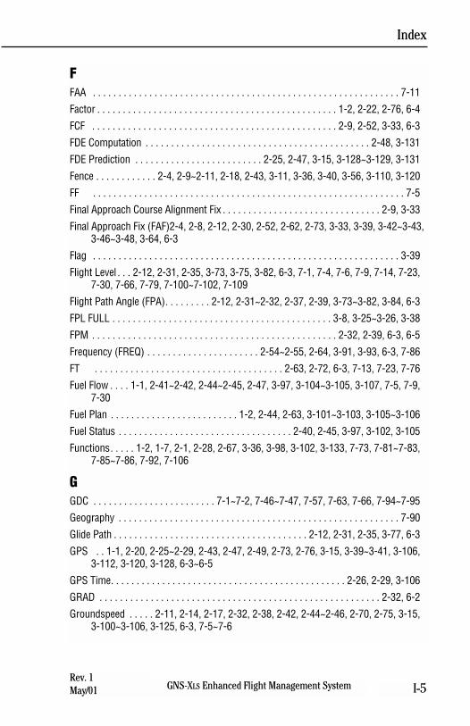
FFAA . . . . . . . . . . . . . . . . . . . . . . . . . . . . . . . . . . . . . . . . . . . . . . . . . . . . . . . . . . . . 7-11
Factor . . . . . . . . . . . . . . . . . . . . . . . . . . . . . . . . . . . . . . . . . . . . . . . 1-2, 2-22, 2-76, 6-4
FCF . . . . . . . . . . . . . . . . . . . . . . . . . . . . . . . . . . . . . . . . . . . . . . . . 2-9, 2-52, 3-33, 6-3
FDE Computation . . . . . . . . . . . . . . . . . . . . . . . . . . . . . . . . . . . . . . . . . . . . 2-48, 3-131
FDE Prediction . . . . . . . . . . . . . . . . . . . . . . . . . 2-25, 2-47, 3-15, 3-128~3-129, 3-131
Fence . . . . . . . . . . . . 2-4, 2-9~2-11, 2-18, 2-43, 3-11, 3-36, 3-40, 3-56, 3-110, 3-120
FF . . . . . . . . . . . . . . . . . . . . . . . . . . . . . . . . . . . . . . . . . . . . . . . . . . . . . . . . . . . . . 7-5
Final Approach Course Alignment Fix . . . . . . . . . . . . . . . . . . . . . . . . . . . . . . . 2-9, 3-33
Final Approach Fix (FAF)2-4, 2-8, 2-12, 2-30, 2-52, 2-62, 2-73, 3-33, 3-39, 3-42~3-43,3-46~3-48, 3-64, 6-3
Flag . . . . . . . . . . . . . . . . . . . . . . . . . . . . . . . . . . . . . . . . . . . . . . . . . . . . . . . . . . . . 3-39
Flight Level . . . 2-12, 2-31, 2-35, 3-73, 3-75, 3-82, 6-3, 7-1, 7-4, 7-6, 7-9, 7-14, 7-23,7-30, 7-66, 7-79, 7-100~7-102, 7-109
Flight Path Angle (FPA). . . . . . . . . 2-12, 2-31~2-32, 2-37, 2-39, 3-73~3-82, 3-84, 6-3
FPL FULL . . . . . . . . . . . . . . . . . . . . . . . . . . . . . . . . . . . . . . . . . . . 3-8, 3-25~3-26, 3-38
FPM . . . . . . . . . . . . . . . . . . . . . . . . . . . . . . . . . . . . . . . . . . . . . . . . 2-32, 2-39, 6-3, 6-5
Frequency (FREQ) . . . . . . . . . . . . . . . . . . . . . . 2-54~2-55, 2-64, 3-91, 3-93, 6-3, 7-86
FT . . . . . . . . . . . . . . . . . . . . . . . . . . . . . . . . . . . . . 2-63, 2-72, 6-3, 7-13, 7-23, 7-76
Fuel Flow . . . . 1-1, 2-41~2-42, 2-44~2-45, 2-47, 3-97, 3-104~3-105, 3-107, 7-5, 7-9,7-30
Fuel Plan . . . . . . . . . . . . . . . . . . . . . . . . . 1-2, 2-44, 2-63, 3-101~3-103, 3-105~3-106
Fuel Status . . . . . . . . . . . . . . . . . . . . . . . . . . . . . . . . . . 2-40, 2-45, 3-97, 3-102, 3-105
Functions. . . . . 1-2, 1-7, 2-1, 2-28, 2-67, 3-36, 3-98, 3-102, 3-133, 7-73, 7-81~7-83,7-85~7-86, 7-92, 7-106
GGDC . . . . . . . . . . . . . . . . . . . . . . . . 7-1~7-2, 7-46~7-47, 7-57, 7-63, 7-66, 7-94~7-95
Geography . . . . . . . . . . . . . . . . . . . . . . . . . . . . . . . . . . . . . . . . . . . . . . . . . . . . . . . 7-90
Glide Path . . . . . . . . . . . . . . . . . . . . . . . . . . . . . . . . . . . . . . 2-12, 2-31, 2-35, 3-77, 6-3
GPS . . 1-1, 2-20, 2-25~2-29, 2-43, 2-47, 2-49, 2-73, 2-76, 3-15, 3-39~3-41, 3-106,3-112, 3-120, 3-128, 6-3~6-5
GPS Time. . . . . . . . . . . . . . . . . . . . . . . . . . . . . . . . . . . . . . . . . . . . . . 2-26, 2-29, 3-106
GRAD . . . . . . . . . . . . . . . . . . . . . . . . . . . . . . . . . . . . . . . . . . . . . . . . . . . . . . . 2-32, 6-2
Groundspeed . . . . . 2-11, 2-14, 2-17, 2-32, 2-38, 2-42, 2-44~2-46, 2-70, 2-75, 3-15,3-100~3-106, 3-125, 6-3, 7-5~7-6
Index
GNS-XLS Enhanced Flight Management System I-5Rev. 1May/01
Guidance . . . . . . . . 2-9, 3-14, 3-39, 3-41, 3-43, 3-46, 3-48, 3-77, 3-85, 3-144~3-145
Guidelines . . . . . . . . . . . . . . . . . . . . . . . . . . . . . . . . . . . . . . . . . . . . . . 2-65, 7-39, 7-42
HH-field . . . . . . . . . . . . . . . . . . . . . . . . . . . . . . . . . . . . . . . . . . . . . . . . . . . . . . . . . . . 2-76
HDOP . . . . . . . . . . . . . . . . . . . . . . . . . . . . . . . . . . . . . . . . . . . . . . . . . . . . . . . 2-29, 6-3
Heading Mode . . . . . . . . . . . . . . . . . . . . . . . . . . 2-9, 2-51, 3-16, 3-39, 3-50, 3-59, 4-2
Headwind . . . . . . . . . . . . . . . . . . . . . . . . . . . . . . . . . . . . . . . . . . . . . . . . . . . . . . . . 2-18
HLTH. . . . . . . . . . . . . . . . . . . . . . . . . . . . . . . . . . . . . . . . . . . . . . . . . . . . . . . . 2-27, 6-3
Holding1-5, 2-4, 2-8, 2-10, 2-13, 2-15~2-17, 2-19, 2-31, 2-56, 2-60~2-62, 2-74, 3-33,3-54, 3-65~3-71, 3-145, 6-3, 7-8, 8-22
Holding Fix. . . . . . . . . . . . . . . . . . . . . . . . . . . 2-10, 2-15~2-17, 2-56, 2-60, 3-68, 8-22
Holding Pattern . . 1-5, 2-4, 2-8, 2-10, 2-13, 2-15~2-16, 2-56, 2-60~2-62, 2-74, 3-33,3-54, 3-65~3-71, 3-145, 6-3
Holding Pattern Entry
Direct Entry . . . . . . . . . . . . . . . . . . . . . . . . . . . . . . . . . . . . . . . . . 2-16, 2-56, 3-65
Parallel Entry . . . . . . . . . . . . . . . . . . . . . . . . . . . . . . . . . . . . . . . . 2-16, 2-56, 2-59
Teardrop Entry . . . . . . . . . . . . . . . . . . . . . . . . . . . . . . . . . . . . . . 2-16, 2-56, 2-58
Holding Status Message. . . . . . . . . . . . . . . . . . . . . . . . . . . . . . . . . . . . . . . . . . . . . 2-16
Horizontal . . . . . . . . . . . . . . . . . . . . . . . . . . . . . . . . . . . . . . . 2-25, 2-29, 2-76, 6-3~6-4
Horizontal Position Error (HPE). . . . . . . . . . . . . . . . . . . . . . . . . . . . . . . 2-25, 2-76, 6-4
HPA . . . . . . . . . . . . . . . . . . . . . . . . . . . . . . . . . . . . . . . . . . . . . . . . . . . . . . . . . 7-2~7-3
HQM . . . . . . . . . . . . . . . . . . . . . . . . . . . . . . . . . . . . . . . . . . . . . . . . . . . . . . . . . . . . 3-16
IICAO Airport Identifier. . . . . . . . . . . . . . . . . . . . . . . . . . . . . . . . . . . . . . . . . . . 1-2, 3-18
ID . . . . . . . . . . . . . . . . . . . . . . . . . . . . 2-54, 7-18, 7-21, 7-69~7-70, 7-92, 8-9, 8-21
Ident-insert . . . . . . . . . . . . . . . . . . . . . . . . . . . . . . . . . . . . . . . . . . . . . . . . . . . . . . 3-127
Identification . . . . . . . . . . . . . . . . . . . . . . . . . . . . . . . . . . . . . . . . 7-15, 7-39, 7-93, 8-1
Identifying . . . . . . . . . . . . . . . . . . . . . . . . . . . . . . . . . . . . . . . . . . . . . 2-68, 3-127, 8-10
Idents . . . . . . . . . . . . . . . . . . . . . . . . . . . . . . . . . . . . . . . . . . . . . . . . . . . . . . 7-19, 7-22
ILS . . . . . . . . . . . . . . . . . . . . . . . . . . . . . . . . . . . . . . . . . . . . . . . . . . . 3-39, 3-93, 6-4
In-flight . . . . . . . . . . . . . . . . . . . . . . . . . . . . . . . . . . . . . . . . . . . . . . . . . . . . . . . . . . . 7-1
Inactive . . . . . . . . . . . . . . . . . . . . . . . . . . . . . . . . . . . . . . . . . . . . . . . 2-30, 2-35, 3-116
Inbound CRS. . . . . . . . . . . . . . . . . . . . . . . . . . . . . . . 2-17, 2-60, 3-65~3-66, 3-68, 6-4
Indented Waypoints . . . . . . . . . . . . . . . . . . . . . . . . . . . . . . . . . . . . . . . . . . . . 2-3, 2-10
Inertial Reference System . . . . . . . . . . . . . . . . . . . . . . . . . . . . . . . . . . . . . . . . 3-15, 6-4
Index
GNS-XLS Enhanced Flight Management SystemI-6Rev. 1
May/01
Index
GNS-XLS Enhanced Flight Management System I-7Rev. 2Sep/02
Initial Approach Fix (IAF) . . . . . . . . . . . . . . 2-4, 2-8, 2-52, 2-62, 3-33, 3-46, 3-48, 6-4
Initialize(d). . . 2-26, 3-4, 3-111, 3-124, 7-4, 7-43, 7-46, 7-48, 7-60, 7-62, 7-64, 7-82,8-1~8-2, 8-11, 8-13~8-14, 8-26~8-27, 8-33
INMARSAT . . . . . . . . . . . . . . . . . . . . . . . . . . . . . . . . . . . . . . . . . . . . . . . . . . . . 7-1, 7-3
INS . . . . . . . . . . . . . . . . . . . . . . . . . . . . . . . . . . . . . . . . . . . . . . . . . . . . . . . . 2-20, 6-4
Inserting . . . . . . . . . . . . . . . . . . . . . . . . . . . . . . . . . . . . 2-70, 3-25~3-26, 3-109, 3-125
Installation . . . . . . . . . . . . . . . . . . . . . . . . . . . . . . . . . . . . . . . . . . 2-5, 3-39, 3-68, 7-73
Integrity . . . . . . . . . . . . . . . . . . . . . . . . . . . . . . . . . . . . . . . . 1-2, 2-43, 2-47, 2-76, 6-5
INTERCEPT BEYOND FIX . . . . . . . . . . . . . . . . . . . . . . . . . . . . . . . . . . . . . . . 2-52, 3-63
Intercept Messages. . . . . . . . . . . . . . . . . . . . . . . . . . . . . . . . . . . . . . . . . . . . 2-52, 3-63
Intercept . . . . 2-13, 2-15, 2-32, 2-51~2-52, 2-69~2-70, 2-74, 3-16, 3-42, 3-46~3-47,3-49~3-51, 3-57, 3-59, 3-61~3-64, 3-87~3-88, 3-111, 3-116, 3-139, 3-142
Interfaced Sensors . . . . . . . . . . . . . . . . . . . . . . . . . . . . . . . . . . . . . . . . . . . . . . . . . 2-20
Interfaces . . . . . . . . . . . . . . . . . . . . . . . . . . . . . . . . . . . . . . . 1-1, 7-1, 7-19~7-22, 7-54
Intersections . . . . . . . . . . . . . . . . . . . . . . . . . . . . . . . . . . . . . . . . . . . . . . . . . 2-63, 2-67
Invert. . . . . . . . . . . . . . . . . . . . . . . . . . . . . . . . . . . . . . . . . . . . . . . . . . . . . . . . 2-5, 3-14
IRS-align. . . . . . . . . . . . . . . . . . . . . . . . . . . . . . . . . . . . . . . . . . . . . . . . . . . . . . . . . 3-15
JJeppesen . . . . . . . . . . . . . . . . . . . . . . . . . . . . . . . . . . . . . . . . . . . . . . . . 2-65, 2-67, 6-4
KKG . . . . . . . . . . . . . . . . . . . . . . . . . . . . . . . . . . . . . . . . . . . . . . . . . . . 2-40, 3-98, 6-4
KHZ . . . . . . . . . . . . . . . . . . . . . . . . . . . . . . . . . . . . . . . . . . . . . . . . . . . . . . . . . . . . . 6-4
KTs . . . . . . . . . . . . . . . . . . . . . . . . . . . . . . . . . . . . . . . . 3-15, 3-128, 7-76~7-77, 7-79
LLand(ing). . . . . . . . . . . . . . . . . . . . . . . . . . . . . . . . . . . 2-46, 3-106, 6-4, 7-9, 8-9, 8-11
Latitude insert. . . . . . . . . . . . . . . . . . . . . . . . . . . . . . . . . 3-5, 3-55~3-56, 3-109, 3-114
Latitudes . . . . . . . . . . . . . . . . . . . . . . . . . . . . . . . . . . . . . . . . . . . . . . . . . . 3-122, 3-146
LB . . . . . . . . . . . . . . . . . . . . . . . . . . . . . . . . . . . . . . . . . . . . . . . 2-40, 2-42, 3-97, 6-4
LDWT . . . . . . . . . . . . . . . . . . . . . . . . . . . . . . . . . . . . . . . . . . . . . . . . . . . . . . . 7-9, 7-30
Leg Change Mode . . . . . . . . . . . . . . 2-15, 2-17, 3-57~3-58, 3-61~3-63, 3-111, 3-144
Leg Fuel. . . . . . . . . . . . . . . . . . . . . . . . . . . . . . . . . . . . . . . . . . . . . . . . . . . . 2-44, 3-105
Legs . . . . . . . . . . . . . . . . . . . . . . 3-98, 3-100~3-102, 3-135~3-136, 3-138, 7-28~7-29
Limitations. . . . . . . . . . . . . . . . . . . . . . . . . . . . . . . . . . . . . . . . . . . . . . 3-15, 3-39, 7-66
Line-of-sight . . . . . . . . . . . . . . . . . . . . . . . . . . . . . . . . . . . . . . . . . . . . . . . . . . . . . . 2-23
Load(ing) . . . . . . . . . . . . . . . . . . . . . . . . 3-22, 3-30, 3-40, 3-67, 3-77, 7-4, 7-88~7-89
LOC . . . . . . . . . . . . . . . . . . . . . . . . . . . . . . . . . . . . . . . . . . . . . . . . . . . . . . . . . . . . 3-39
LON . . . . . . . . . . . . . . . . . . . . . . . . . . . . . . . . . 6-4, 7-8, 7-11, 7-13, 7-50, 7-64, 7-70
Longitude insert . . . . . . . . . . . . . . . . . . . . . . . . . . . . . . . 3-5, 3-55~3-56, 3-109, 3-114
LVL . . . . . . . . . . . . . . . . . . . . . . . . . . . . . . . . . . . . . . . . . . . . . . . . . . . . . . . . 7-9, 7-30
MMAG . . . . . . . . . . . . . . . . . . . . . . . . . . . . . . . . . . . . . . . . . . . . . . 2-14, 2-60, 3-122, 6-4
Magnetic Variation . . . . . . . . . . 2-19, 2-64, 2-68, 2-72, 3-117, 3-122, 3-127, 6-4, 6-7
Manual Fuel Flow. . . . . . . . . . . . . . . . . . . . . . . . . . . . . . . . . . . . . . . . 2-47, 3-97, 3-104
Manual Ground Speed . . . . . . . . . . . . . . . . . . . . . . . . . . . . . . . . . . . . . . . . . . . . . . 2-43
MAX . . . . . . . . . . . . . . . . . . . . . . . . . . . . . . . . . . . . . . . . . . . . . . . . . . . . . . . . . . . . 2-60
MDA . . . . . . . . . . . . . . . . . . . . . . . . . . . . . . . . . . . . . . . . . . . . . . . . . . . . . . . 2-12, 2-30
MEM . . . . . . . . . . . . . . . . . . . . . . . . . . . . . . . . . . . . . . . . . 2-74, 2-76, 3-8, 3-38, 3-126
MEM FULL . . . . . . . . . . . . . . . . . . . . . . . . . . . . . . . . . . . . . . . . . 2-76, 3-8, 3-38, 3-126
Message Section . . . . . . . . . . . . . . . . . . . . . . . . . . . . . . . . . . . . . . . . . . . . . . . . . . 2-71
METAR . . . . . . . . . . . . . . . . . . . . . . . . . . . . . . . . . . . . . 7-73, 7-75, 7-97, 7-105~7-106
Miscompare . . . . . . . . . . . . . . . . . . . . . . . . . . . . . . . . . . . . . . . . . . . . . . . . . . . . . . 2-75
Missed Approach Point . . . . . . . . . . . . . . . . . . . . . . . . 2-4, 2-62, 3-16, 3-33, 3-39, 6-5
Missed Approach Procedure. . . . . . . . . . . . . . . . . . . 2-9, 3-36, 3-39~3-40, 3-50~3-51
MOD . . . . . . . . . . . . . . . . . . . . . . . . . . . . . . . . . . . . . . . . . . . . . . . . . . . . . . . . . 6-6, 7-1
Name. . . . . . . . . . . . . . . . . . . . . . . . . . . . . . . . . . . . . 2-56, 3-12, 6-4, 7-15, 7-39, 7-86
Naming . . . . . . . . . . . . . . . . . . . . . . . . . . . . . . . . . . . . . . 1-2, 3-18, 3-49, 3-134~3-135
NAT . . . . . . . . . . . . . . . . . . . . . . . . . . . . . . . . . . . . . . . . . . . . . . . . . . . . . . . 7-11, 7-68
Navaids . . . . . . . . . . . . . . . . . . . . . . . . . . . . . . . . . . . . . . . 1-2, 2-63, 3-15, 3-93, 3-124
Navigate . . . . . . . . . . . . . . . . . . . . . . . . . . . . . . . . . . . . . . . . . . . . . . . . . . . . 3-15, 7-28
Navigational . . . . . . . . . . . . . . . . . . . . . . . . . . . . . . . . . . . . . . . . . . . . . . . . . . . . . . . 8-1
NAVs . . . . . . . . . . . . . . . . . . . . . . . . . . . . . . . . . . . . . . . . . . . . . . . . . . . . . . . . 1-2, 3-92
NB . . . . . . . . . . . . . . . . . . . . . . . . . . . . . . . . . . . . . . . . . . . . . . . . . . . . . . . . . . . . 2-65
NDB . . . . . . . . . . . . . . . . . . . . . . . . . . . . . . . 2-8, 2-64~2-65, 2-74, 3-8, 3-39, 6-5, 6-7
NDB-WW . . . . . . . . . . . . . . . . . . . . . . . . . . . . . . . . . . . . . . . . . . . . . . . . . . . . . . . . 2-74
NEXRAD . . . . . . . . . . . . . . . . . . . . . . . . . . . . . . 7-73~7-75, 7-94~7-105, 7-109~7-110
NO AFIS FLT PLANS ON DISK . . . . . . . . . . . . . . . . . . . . . . . . . . . . . . . . . . . . . . . . . 7-3
NO APPROACH AVAILABLE . . . . . . . . . . . . . . . . . . . . . . . . . . . . . . . . . . . . . . . . . . . 2-7
No APPROACH Available . . . . . . . . . . . . . . . . . . . . . . . . . . . . . . . . . . . . . . . . . . . . . 2-7
NO ARC INTERCEPT . . . . . . . . . . . . . . . . . . . . . . . . . . . . . . . . . 2-52, 2-75, 3-47, 3-63
Index
GNS-XLS Enhanced Flight Management SystemI-8Rev. 1
May/01
NO AUTO LEG CHG. . . . . . . . . . . . . . . . . . . . . 2-74, 3-56, 3-110~3-111, 3-120~3-121
NO COURSE INTERCEPT. . . . . . . . . . . . . . . . . . . . . . . . . . . . . . . . . . . 2-52, 2-75, 3-63
No Data Received . . . . . . . . . . . . . . . . . . . . . . . . . . . . . . . . . . . . . . . . . . . . . . . . . . . 2-1
NO DISK . . . . . . . . . . . . . . . . . . . . . . . . . . . . . . . . . . . . . . . . . . . . . . . . . . . . . . . . . . 7-3
NO FPL AVAIL . . . . . . . . . . . . . . . . . . . . . . . . . . . . . . . . . . . . . . . . . . . . . . . . . . . . . 3-7
NO ROOM ON FPL . . . . . . . . . . . . . . . . . . . . . . . . . . . . . . . . . . . . . . . . . . . . . . . . . . 3-8
NO SIDS AVAILABLE . . . . . . . . . . . . . . . . . . . . . . . . . . . . . . . . . . . . . . . . . . . 2-5, 3-19
No SIDs Available . . . . . . . . . . . . . . . . . . . . . . . . . . . . . . . . . . . . . . . . . . . . . . 2-5, 3-19
NO SIGMETS. . . . . . . . . . . . . . . . . . . . . . . . . . . . . . . . . . . . . . . . . . . . . . . . . 7-12, 7-32
NO STARS AVAILABLE . . . . . . . . . . . . . . . . . . . . . . . . . . . . . . . . . . . . . . . . . . 2-6, 3-28
Non-directional . . . . . . . . . . . . . . . . . . . . . . . . . . . . . . . . . . . . . . . . . . . . . . . . 2-65, 6-5
Non-enterable . . . . . . . . . . . . . . . . . . . . . . . . . . . . . . . . . . . . . . . . . . . . . . . . . . . . . 3-86
Non-ICAO . . . . . . . . . . . . . . . . . . . . . . . . . . . . . . . . . . . . . . . . . . . . . . . . . . . . . . . . . 3-3
Non-IRS . . . . . . . . . . . . . . . . . . . . . . . . . . . . . . . . . . . . . . . . . . . . . . . . . . . . . . . . . . 3-3
Non-precision . . . . . . . . . . . . . . . . . . . . . . . . . . . . . . . . . . . . . . . . . . . . . 2-4, 3-8, 3-63
Non-standard . . . . . . . . . . . . . . . . . . . . . . . . . . . . . . . . . . . . . . . . . . . . . . . . . . . . . 2-60
NOPT . . . . . . . . . . . . . . . . . . . . . . . . . . . . . . . . . . . . . . . . . . . . . . . . . . . . . . . . . . . 3-44
NOTAMS. . . . . . . . . . . . . . . . . . . . . . . . . . . . . . . . . . . . . . . . . . . . . . . . . . . . . . . . . 7-13
NX . . . . . . . . . . . 2-13~2-14, 2-17, 2-19, 3-49, 3-69, 6-5, 7-97~7-99, 7-101, 7-103
OOceanic/Remote Operation . . . . . . . 2-26, 2-47~2-48, 2-70, 3-10, 3-15, 3-128~3-129
Offset(s) . . . . . . 1-2, 2-11~2-13, 2-19, 2-31, 2-35, 2-39, 2-63, 2-68, 3-8, 3-53, 3-56,3-75~3-76, 3-81~3-84, 3-86, 3-102, 3-109, 3-115~3-116, 3-118, 3-121,3-125~3-128
Options . . . . 3-34, 3-50, 3-68, 3-81, 7-10, 7-54, 7-74, 7-77, 7-81, 7-86, 7-96, 7-103,7-107
Outer Markers. . . . . . . . . . . . . . . . . . . . . . . . . . . . . . . . . . . . . . . . . . . . . . . . . . . . . 2-66
Overflying . . . . . . . . . . . . . . . . . . . . . . . . . . . . . . . . . . . . . . . . . . . . . . . . . 3-113, 3-115
Overlay . . . . . . . . . . . . . . . . . . . . . . . . . . . . . . . . . . . . . 2-28, 3-39, 7-79, 7-102, 7-109
PParallax Adjustment . . . . . . . . . . . . . . . . . . . . . . . . . . . . . . . . . . . . . . . . . . . . . 1-4, 3-1
Parameters 2-26, 2-56, 3-65, 3-81, 3-107, 3-133~3-134, 3-136, 3-138, 3-140, 3-142
Part Number . . . . . . . . . . . . . . . . . . . . . . . . . . . . . . . . . . . . . . . . . . . . . . . . . . . . . . . 2-2
Path Descent . . . . . . . . . . . . . . . . . . . . 2-31, 2-35, 2-37, 2-39, 3-76, 3-80, 3-83, 3-85
PCMCIA Card . . . . . . . . . . . . . . . . . . . . . . . . . . . . . . . . . . . . . . . . . . . . . . . . . 1-2, 7-73
Index
GNS-XLS Enhanced Flight Management System I-9Rev. 1May/01
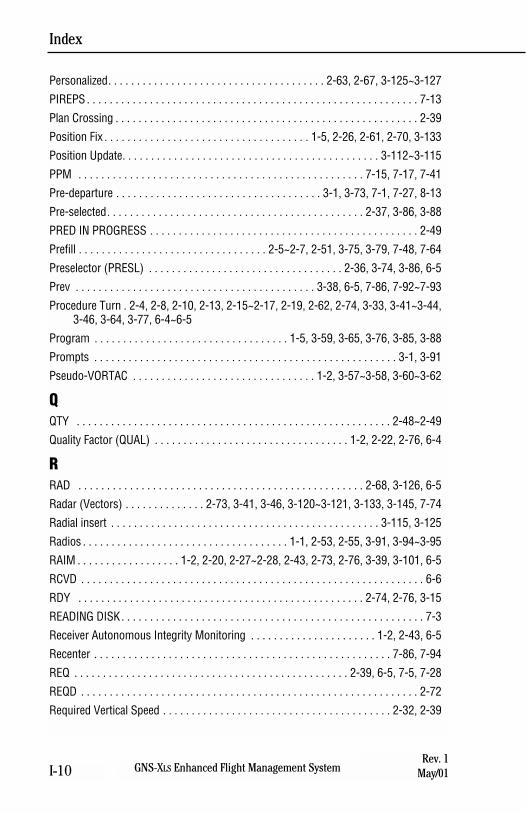
Personalized. . . . . . . . . . . . . . . . . . . . . . . . . . . . . . . . . . . . . . 2-63, 2-67, 3-125~3-127
PIREPS . . . . . . . . . . . . . . . . . . . . . . . . . . . . . . . . . . . . . . . . . . . . . . . . . . . . . . . . . . 7-13
Plan Crossing . . . . . . . . . . . . . . . . . . . . . . . . . . . . . . . . . . . . . . . . . . . . . . . . . . . . . 2-39
Position Fix . . . . . . . . . . . . . . . . . . . . . . . . . . . . . . . . . . . . 1-5, 2-26, 2-61, 2-70, 3-133
Position Update. . . . . . . . . . . . . . . . . . . . . . . . . . . . . . . . . . . . . . . . . . . . . 3-112~3-115
PPM . . . . . . . . . . . . . . . . . . . . . . . . . . . . . . . . . . . . . . . . . . . . . . . . . . 7-15, 7-17, 7-41
Pre-departure . . . . . . . . . . . . . . . . . . . . . . . . . . . . . . . . . . . . 3-1, 3-73, 7-1, 7-27, 8-13
Pre-selected. . . . . . . . . . . . . . . . . . . . . . . . . . . . . . . . . . . . . . . . . . . . . 2-37, 3-86, 3-88
PRED IN PROGRESS . . . . . . . . . . . . . . . . . . . . . . . . . . . . . . . . . . . . . . . . . . . . . . . 2-49
Prefill . . . . . . . . . . . . . . . . . . . . . . . . . . . . . . . . . 2-5~2-7, 2-51, 3-75, 3-79, 7-48, 7-64
Preselector (PRESL) . . . . . . . . . . . . . . . . . . . . . . . . . . . . . . . . . . 2-36, 3-74, 3-86, 6-5
Prev . . . . . . . . . . . . . . . . . . . . . . . . . . . . . . . . . . . . . . . . . . 3-38, 6-5, 7-86, 7-92~7-93
Procedure Turn . 2-4, 2-8, 2-10, 2-13, 2-15~2-17, 2-19, 2-62, 2-74, 3-33, 3-41~3-44,3-46, 3-64, 3-77, 6-4~6-5
Program . . . . . . . . . . . . . . . . . . . . . . . . . . . . . . . . . . 1-5, 3-59, 3-65, 3-76, 3-85, 3-88
Prompts . . . . . . . . . . . . . . . . . . . . . . . . . . . . . . . . . . . . . . . . . . . . . . . . . . . . . 3-1, 3-91
Pseudo-VORTAC . . . . . . . . . . . . . . . . . . . . . . . . . . . . . . . . 1-2, 3-57~3-58, 3-60~3-62
QQTY . . . . . . . . . . . . . . . . . . . . . . . . . . . . . . . . . . . . . . . . . . . . . . . . . . . . . . . 2-48~2-49
Quality Factor (QUAL) . . . . . . . . . . . . . . . . . . . . . . . . . . . . . . . . . . 1-2, 2-22, 2-76, 6-4
RRAD . . . . . . . . . . . . . . . . . . . . . . . . . . . . . . . . . . . . . . . . . . . . . . . . . . 2-68, 3-126, 6-5
Radar (Vectors) . . . . . . . . . . . . . . 2-73, 3-41, 3-46, 3-120~3-121, 3-133, 3-145, 7-74
Radial insert . . . . . . . . . . . . . . . . . . . . . . . . . . . . . . . . . . . . . . . . . . . . . . . 3-115, 3-125
Radios . . . . . . . . . . . . . . . . . . . . . . . . . . . . . . . . . . . . 1-1, 2-53, 2-55, 3-91, 3-94~3-95
RAIM . . . . . . . . . . . . . . . . . . 1-2, 2-20, 2-27~2-28, 2-43, 2-73, 2-76, 3-39, 3-101, 6-5
RCVD . . . . . . . . . . . . . . . . . . . . . . . . . . . . . . . . . . . . . . . . . . . . . . . . . . . . . . . . . . . . 6-6
RDY . . . . . . . . . . . . . . . . . . . . . . . . . . . . . . . . . . . . . . . . . . . . . . . . . . 2-74, 2-76, 3-15
READING DISK. . . . . . . . . . . . . . . . . . . . . . . . . . . . . . . . . . . . . . . . . . . . . . . . . . . . . 7-3
Receiver Autonomous Integrity Monitoring . . . . . . . . . . . . . . . . . . . . . . 1-2, 2-43, 6-5
Recenter . . . . . . . . . . . . . . . . . . . . . . . . . . . . . . . . . . . . . . . . . . . . . . . . . . . . 7-86, 7-94
REQ . . . . . . . . . . . . . . . . . . . . . . . . . . . . . . . . . . . . . . . . . . . . . . . . 2-39, 6-5, 7-5, 7-28
REQD . . . . . . . . . . . . . . . . . . . . . . . . . . . . . . . . . . . . . . . . . . . . . . . . . . . . . . . . . . . 2-72
Required Vertical Speed . . . . . . . . . . . . . . . . . . . . . . . . . . . . . . . . . . . . . . . . 2-32, 2-39
Index
GNS-XLS Enhanced Flight Management SystemI-10Rev. 1
May/01
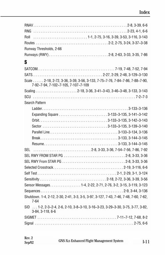
RNAV . . . . . . . . . . . . . . . . . . . . . . . . . . . . . . . . . . . . . . . . . . . . . . . . . . . . 2-8, 3-39, 6-6
RNG . . . . . . . . . . . . . . . . . . . . . . . . . . . . . . . . . . . . . . . . . . . . . . . . . . . . 2-23, 4-1, 6-6
Roll . . . . . . . . . . . . . . . . . . . . . . . . . . . . . . 1-1, 2-75, 3-16, 3-39, 3-53, 3-116, 3-143
Routes . . . . . . . . . . . . . . . . . . . . . . . . . . . . . . . . . . . . . . . . 2-2, 2-75, 3-24, 3-37~3-38
Runway Thresholds, 2-66
Runways (RWY) . . . . . . . . . . . . . . . . . . . . . . . . . . . . . . . . . 2-8, 2-63, 3-33, 3-35, 7-86
SSATCOM. . . . . . . . . . . . . . . . . . . . . . . . . . . . . . . . . . . . . . . . . . . 7-19, 7-48, 7-52, 7-94
SATS. . . . . . . . . . . . . . . . . . . . . . . . . . . . . . . . . . . . . . . 2-27, 2-29, 2-48, 3-129~3-130
Scale . . . . . . 2-18, 2-72, 3-36, 3-39, 3-56, 3-133, 7-75~7-76, 7-84~7-86, 7-88~7-90,7-92~7-94, 7-102~7-105, 7-107~7-109
Scaling . . . . . . . . . . . . . . . . . . . . . . . 2-18, 3-36, 3-41~3-43, 3-46~3-48, 3-133, 3-143
SCU . . . . . . . . . . . . . . . . . . . . . . . . . . . . . . . . . . . . . . . . . . . . . . . . . . . . . . . . . 7-2~7-3
Search Pattern
Ladder. . . . . . . . . . . . . . . . . . . . . . . . . . . . . . . . . . . . . . . . . . . . . . . . 3-133~3-136
Expanding Square . . . . . . . . . . . . . . . . . . . . . . . . . . . 3-133~3-135, 3-141~3-142
Orbit. . . . . . . . . . . . . . . . . . . . . . . . . . . . . . . . . . . . . . 3-133~3-135, 3-142~3-143
Sector . . . . . . . . . . . . . . . . . . . . . . . . . . . . . . . . . . . . 3-133~3-135, 3-139~3-140
Parallel Line. . . . . . . . . . . . . . . . . . . . . . . . . . . . . . . . . . . . . . 3-133~3-134, 3-136
Break . . . . . . . . . . . . . . . . . . . . . . . . . . . . . . . . . . . . . . . . . . . 3-133, 3-144~3-145
Resume. . . . . . . . . . . . . . . . . . . . . . . . . . . . . . . . . . . . . . . . . 3-133, 3-144~3-145
SEL . . . . . . . . . . . . . . . . . . . . . . . . . . . . . . . . 2-8, 3-33, 3-36, 7-54~7-56, 7-86, 7-92
SEL RWY FROM STAR PG . . . . . . . . . . . . . . . . . . . . . . . . . . . . . . . . . . 2-8, 3-33, 3-36
SEL RWY From STAR PG . . . . . . . . . . . . . . . . . . . . . . . . . . . . . . . . . . . 2-8, 3-33, 3-36
Selected Crosstrack. . . . . . . . . . . . . . . . . . . . . . . . . . . . . . . . . . . . . . . 2-19, 3-116, 6-6
Self Test . . . . . . . . . . . . . . . . . . . . . . . . . . . . . . . . . . . . . . . . . . . . 2-1, 2-29, 3-1, 3-124
Sensitivity . . . . . . . . . . . . . . . . . . . . . . . . . . . . . . . . . . . . . 2-18, 2-72, 3-36, 3-39, 3-56
Sensor Messages. . . . . . . . . . . . . . . . . 1-4, 2-22, 2-71, 2-76, 3-2, 3-15, 3-119, 3-123
Sequences . . . . . . . . . . . . . . . . . . . . . . . . . . . . . . . . . . . . . . . . . . . . . . 2-9, 3-44, 3-136
Shutdown. 1-4, 2-12, 2-30, 2-41, 3-3, 3-5, 3-97, 3-127, 7-43, 7-46, 7-48, 7-60, 7-62,7-64
SID . . . 1-2, 2-3~2-4, 2-6, 2-10, 3-8~3-10, 3-16~3-23, 3-29~3-30, 3-75, 3-77, 3-82,3-84, 3-118, 6-6
SIGMET . . . . . . . . . . . . . . . . . . . . . . . . . . . . . . . . . . . . . . . . . . . . 7-11~7-12, 7-68, 8-2
Signal . . . . . . . . . . . . . . . . . . . . . . . . . . . . . . . . . . . . . . . . . . . . . . . . . . . . . . . 2-75, 6-6
Index
GNS-XLS Enhanced Flight Management System I-11Rev. 2Sep/02
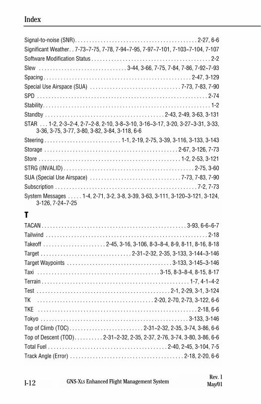
Index
GNS-XLS Enhanced Flight Management SystemI-12Rev. 1
May/01
Signal-to-noise (SNR). . . . . . . . . . . . . . . . . . . . . . . . . . . . . . . . . . . . . . . . . . . 2-27, 6-6
Significant Weather. . 7-73~7-75, 7-78, 7-94~7-95, 7-97~7-101, 7-103~7-104, 7-107
Software Modification Status . . . . . . . . . . . . . . . . . . . . . . . . . . . . . . . . . . . . . . . . . . 2-2
Slew . . . . . . . . . . . . . . . . . . . . . . . . . . . . . . . 3-44, 3-66, 7-75, 7-84, 7-86, 7-92~7-93
Spacing . . . . . . . . . . . . . . . . . . . . . . . . . . . . . . . . . . . . . . . . . . . . . . . . . . . . 2-47, 3-129
Special Use Airspace (SUA) . . . . . . . . . . . . . . . . . . . . . . . . . . . . . . . . 7-73, 7-83, 7-90
SPD . . . . . . . . . . . . . . . . . . . . . . . . . . . . . . . . . . . . . . . . . . . . . . . . . . . . . . . . . . . . 2-74
Stability. . . . . . . . . . . . . . . . . . . . . . . . . . . . . . . . . . . . . . . . . . . . . . . . . . . . . . . . . . . 1-2
Standby . . . . . . . . . . . . . . . . . . . . . . . . . . . . . . . . . . . . . . . . . . 2-43, 2-49, 3-63, 3-131
STAR . . . 1-2, 2-3~2-4, 2-7~2-8, 2-10, 3-8~3-10, 3-16~3-17, 3-20, 3-27~3-31, 3-33,3-36, 3-75, 3-77, 3-80, 3-82, 3-84, 3-118, 6-6
Steering . . . . . . . . . . . . . . . . . . . . . . . . . . . 1-1, 2-19, 2-75, 3-39, 3-116, 3-133, 3-143
Storage . . . . . . . . . . . . . . . . . . . . . . . . . . . . . . . . . . . . . . . . . . . . . . . 2-67, 3-126, 7-73
Store . . . . . . . . . . . . . . . . . . . . . . . . . . . . . . . . . . . . . . . . . . . . . . . . . . 1-2, 2-53, 3-121
STRG (INVALID) . . . . . . . . . . . . . . . . . . . . . . . . . . . . . . . . . . . . . . . . . . . . . . 2-75, 3-60
SUA (Special Use Airspace) . . . . . . . . . . . . . . . . . . . . . . . . . . . . . . . . 7-73, 7-83, 7-90
Subscription . . . . . . . . . . . . . . . . . . . . . . . . . . . . . . . . . . . . . . . . . . . . . . . . . . 7-2, 7-73
System Messages . . . . . 1-4, 2-71, 3-2, 3-8, 3-39, 3-63, 3-111, 3-120~3-121, 3-124,3-126, 7-24~7-25
TTACAN . . . . . . . . . . . . . . . . . . . . . . . . . . . . . . . . . . . . . . . . . . . . . . . . . . . 3-93, 6-6~6-7
Tailwind . . . . . . . . . . . . . . . . . . . . . . . . . . . . . . . . . . . . . . . . . . . . . . . . . . . . . . . . . 2-18
Takeoff . . . . . . . . . . . . . . . . . . . . . . 2-45, 3-16, 3-106, 8-3~8-4, 8-9, 8-11, 8-16, 8-18
Target . . . . . . . . . . . . . . . . . . . . . . . . . . . . . . . . 2-31~2-32, 2-35, 3-133, 3-144~3-146
Target Waypoints . . . . . . . . . . . . . . . . . . . . . . . . . . . . . . . . . . . . . 3-133, 3-145~3-146
Taxi . . . . . . . . . . . . . . . . . . . . . . . . . . . . . . . . . . . . . . . . . . . 3-15, 8-3~8-4, 8-15, 8-17
Terrain . . . . . . . . . . . . . . . . . . . . . . . . . . . . . . . . . . . . . . . . . . . . . . . . . . . . 1-7, 4-1~4-2
Test . . . . . . . . . . . . . . . . . . . . . . . . . . . . . . . . . . . . . . . . . . . . . . . 2-1, 2-29, 3-1, 3-124
TK . . . . . . . . . . . . . . . . . . . . . . . . . . . . . . . . . . . . . . . . . 2-20, 2-70, 2-73, 3-122, 6-6
TKE . . . . . . . . . . . . . . . . . . . . . . . . . . . . . . . . . . . . . . . . . . . . . . . . . . . . . . . . 2-18, 6-6
Tokyo . . . . . . . . . . . . . . . . . . . . . . . . . . . . . . . . . . . . . . . . . . . . . . . . . . . . 3-133, 3-146
Top of Climb (TOC) . . . . . . . . . . . . . . . . . . . . . . . . . . 2-31~2-32, 2-35, 3-74, 3-86, 6-6
Top of Descent (TOD). . . . . . . . . . 2-31~2-32, 2-35, 2-37, 2-76, 3-74, 3-80, 3-86, 6-6
Total Fuel . . . . . . . . . . . . . . . . . . . . . . . . . . . . . . . . . . . . . . . . . . 2-40, 2-45, 3-104, 7-5
Track Angle (Error) . . . . . . . . . . . . . . . . . . . . . . . . . . . . . . . . . . . . . . . . 2-18, 2-20, 6-6
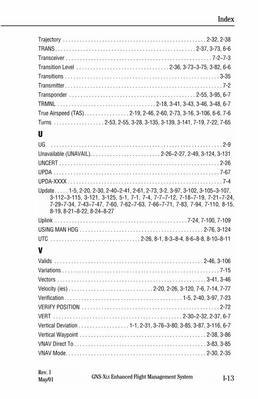
Index
GNS-XLS Enhanced Flight Management System I-13Rev. 1May/01
Trajectory . . . . . . . . . . . . . . . . . . . . . . . . . . . . . . . . . . . . . . . . . . . . . . . . . . . 2-32, 2-38
TRANS . . . . . . . . . . . . . . . . . . . . . . . . . . . . . . . . . . . . . . . . . . . . . . . . . . 2-37, 3-73, 6-6
Transceiver . . . . . . . . . . . . . . . . . . . . . . . . . . . . . . . . . . . . . . . . . . . . . . . . . . . . 7-2~7-3
Transition Level . . . . . . . . . . . . . . . . . . . . . . . . . . . . . . . . . 2-36, 3-73~3-75, 3-82, 6-6
Transitions . . . . . . . . . . . . . . . . . . . . . . . . . . . . . . . . . . . . . . . . . . . . . . . . . . . . . . . 3-35
Transmitter . . . . . . . . . . . . . . . . . . . . . . . . . . . . . . . . . . . . . . . . . . . . . . . . . . . . . . . . 7-2
Transponder . . . . . . . . . . . . . . . . . . . . . . . . . . . . . . . . . . . . . . . . . . . . . 2-55, 3-95, 6-7
TRMNL . . . . . . . . . . . . . . . . . . . . . . . . . . . . . . . . . . . 2-18, 3-41, 3-43, 3-46, 3-48, 6-7
True Airspeed (TAS). . . . . . . . . . . . . . . . 2-19, 2-46, 2-60, 2-73, 3-16, 3-106, 6-6, 7-6
Turns . . . . . . . . . . . . . . . . . . 2-53, 2-55, 3-28, 3-135, 3-139, 3-141, 7-19, 7-22, 7-65
UUG . . . . . . . . . . . . . . . . . . . . . . . . . . . . . . . . . . . . . . . . . . . . . . . . . . . . . . . . . . . . . 2-9
Unavailable (UNAVAIL). . . . . . . . . . . . . . . . . . . . . . . . . 2-26~2-27, 2-49, 3-124, 3-131
UNCERT . . . . . . . . . . . . . . . . . . . . . . . . . . . . . . . . . . . . . . . . . . . . . . . . . . . . . . . . . 2-26
UPDA . . . . . . . . . . . . . . . . . . . . . . . . . . . . . . . . . . . . . . . . . . . . . . . . . . . . . . . . . . . 7-67
UPDA-XXXX . . . . . . . . . . . . . . . . . . . . . . . . . . . . . . . . . . . . . . . . . . . . . . . . . . . . . . . 7-4
Update. . . . . 1-5, 2-20, 2-30, 2-40~2-41, 2-61, 2-73, 3-2, 3-97, 3-102, 3-105~3-107,3-112~3-115, 3-121, 3-125, 5-1, 7-1, 7-4, 7-7~7-12, 7-18~7-19, 7-21~7-24,7-29~7-34, 7-43~7-47, 7-60, 7-62~7-63, 7-66~7-71, 7-83, 7-94, 7-110, 8-15,8-19, 8-21~8-22, 8-24~8-27
Uplink . . . . . . . . . . . . . . . . . . . . . . . . . . . . . . . . . . . . . . . . . . . . . . . 7-24, 7-100, 7-109
USING MAN HDG . . . . . . . . . . . . . . . . . . . . . . . . . . . . . . . . . . . . . . . . . . . . 2-76, 3-124
UTC . . . . . . . . . . . . . . . . . . . . . . . . . . . . . . . . 2-26, 8-1, 8-3~8-4, 8-6~8-8, 8-10~8-11
VValids . . . . . . . . . . . . . . . . . . . . . . . . . . . . . . . . . . . . . . . . . . . . . . . . . . . . . 2-46, 3-106
Variations . . . . . . . . . . . . . . . . . . . . . . . . . . . . . . . . . . . . . . . . . . . . . . . . . . . . . . . . 7-15
Vectors . . . . . . . . . . . . . . . . . . . . . . . . . . . . . . . . . . . . . . . . . . . . . . . . . . . . . 3-41, 3-46
Velocity (ies) . . . . . . . . . . . . . . . . . . . . . . . . . . . . . . 2-20, 2-26, 3-120, 7-6, 7-14, 7-77
Verification . . . . . . . . . . . . . . . . . . . . . . . . . . . . . . . . . . . . . . . . . . 1-5, 2-40, 3-97, 7-23
VERIFY POSITION . . . . . . . . . . . . . . . . . . . . . . . . . . . . . . . . . . . . . . . . . . . . . . . . . 2-72
VERT . . . . . . . . . . . . . . . . . . . . . . . . . . . . . . . . . . . . . . . . . . . . . . 2-30~2-32, 2-37, 6-7
Vertical Deviation . . . . . . . . . . . . . . . . . . 1-1, 2-31, 3-76~3-80, 3-85, 3-87, 3-116, 6-7
Vertical Waypoint . . . . . . . . . . . . . . . . . . . . . . . . . . . . . . . . . . . . . . . . . . . . . 2-38, 3-86
VNAV Direct To . . . . . . . . . . . . . . . . . . . . . . . . . . . . . . . . . . . . . . . . . . . . . . . 3-83, 3-85
VNAV Mode. . . . . . . . . . . . . . . . . . . . . . . . . . . . . . . . . . . . . . . . . . . . . . . . . . 2-30, 2-35
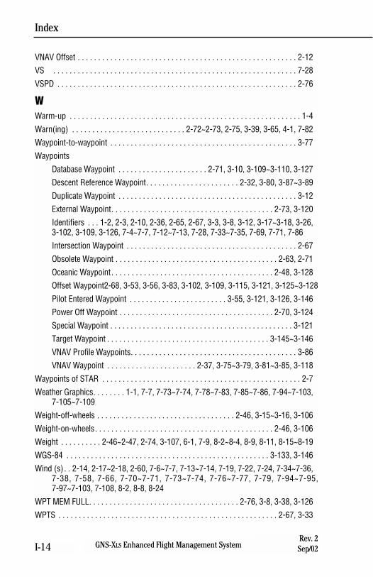
VNAV Offset . . . . . . . . . . . . . . . . . . . . . . . . . . . . . . . . . . . . . . . . . . . . . . . . . . . . . . 2-12
VS . . . . . . . . . . . . . . . . . . . . . . . . . . . . . . . . . . . . . . . . . . . . . . . . . . . . . . . . . . . . 7-28
VSPD . . . . . . . . . . . . . . . . . . . . . . . . . . . . . . . . . . . . . . . . . . . . . . . . . . . . . . . . . . . 2-76
WWarm-up . . . . . . . . . . . . . . . . . . . . . . . . . . . . . . . . . . . . . . . . . . . . . . . . . . . . . . . . . 1-4
Warn(ing) . . . . . . . . . . . . . . . . . . . . . . . . . . . . 2-72~2-73, 2-75, 3-39, 3-65, 4-1, 7-82
Waypoint-to-waypoint . . . . . . . . . . . . . . . . . . . . . . . . . . . . . . . . . . . . . . . . . . . . . . 3-77
Waypoints
Database Waypoint . . . . . . . . . . . . . . . . . . . . . . 2-71, 3-10, 3-109~3-110, 3-127
Descent Reference Waypoint. . . . . . . . . . . . . . . . . . . . . . . 2-32, 3-80, 3-87~3-89
Duplicate Waypoint . . . . . . . . . . . . . . . . . . . . . . . . . . . . . . . . . . . . . . . . . . . . 3-12
External Waypoint. . . . . . . . . . . . . . . . . . . . . . . . . . . . . . . . . . . . . . . . 2-73, 3-120
Identifiers . . . 1-2, 2-3, 2-10, 2-36, 2-65, 2-67, 3-3, 3-8, 3-12, 3-17~3-18, 3-26,3-102, 3-109, 3-126, 7-4~7-7, 7-12~7-13, 7-28, 7-33~7-35, 7-69, 7-71, 7-86
Intersection Waypoint . . . . . . . . . . . . . . . . . . . . . . . . . . . . . . . . . . . . . . . . . . 2-67
Obsolete Waypoint . . . . . . . . . . . . . . . . . . . . . . . . . . . . . . . . . . . . . . . . 2-63, 2-71
Oceanic Waypoint. . . . . . . . . . . . . . . . . . . . . . . . . . . . . . . . . . . . . . . . 2-48, 3-128
Offset Waypoint2-68, 3-53, 3-56, 3-83, 3-102, 3-109, 3-115, 3-121, 3-125~3-128
Pilot Entered Waypoint . . . . . . . . . . . . . . . . . . . . . . . . 3-55, 3-121, 3-126, 3-146
Power Off Waypoint . . . . . . . . . . . . . . . . . . . . . . . . . . . . . . . . . . . . . . 2-70, 3-124
Special Waypoint . . . . . . . . . . . . . . . . . . . . . . . . . . . . . . . . . . . . . . . . . . . . . 3-121
Target Waypoint . . . . . . . . . . . . . . . . . . . . . . . . . . . . . . . . . . . . . . . . 3-145~3-146
VNAV Profile Waypoints. . . . . . . . . . . . . . . . . . . . . . . . . . . . . . . . . . . . . . . . . 3-86
VNAV Waypoint . . . . . . . . . . . . . . . . . . . . . . 2-37, 3-75~3-79, 3-81~3-85, 3-118
Waypoints of STAR . . . . . . . . . . . . . . . . . . . . . . . . . . . . . . . . . . . . . . . . . . . . . . . . . 2-7
Weather Graphics. . . . . . . . 1-1, 7-7, 7-73~7-74, 7-78~7-83, 7-85~7-86, 7-94~7-103,7-105~7-109
Weight-off-wheels . . . . . . . . . . . . . . . . . . . . . . . . . . . . . . . . . . 2-46, 3-15~3-16, 3-106
Weight-on-wheels. . . . . . . . . . . . . . . . . . . . . . . . . . . . . . . . . . . . . . . . . . . . 2-46, 3-106
Weight . . . . . . . . . . 2-46~2-47, 2-74, 3-107, 6-1, 7-9, 8-2~8-4, 8-9, 8-11, 8-15~8-19
WGS-84 . . . . . . . . . . . . . . . . . . . . . . . . . . . . . . . . . . . . . . . . . . . . . . . . . . 3-133, 3-146
Wind (s) . . 2-14, 2-17~2-18, 2-60, 7-6~7-7, 7-13~7-14, 7-19, 7-22, 7-24, 7-34~7-36,7-38, 7-58, 7-66, 7-70~7-71, 7-73~7-74, 7-76~7-77, 7-79, 7-94~7-95,7-97~7-103, 7-108, 8-2, 8-8, 8-24
WPT MEM FULL. . . . . . . . . . . . . . . . . . . . . . . . . . . . . . . . . . . . . 2-76, 3-8, 3-38, 3-126
WPTS . . . . . . . . . . . . . . . . . . . . . . . . . . . . . . . . . . . . . . . . . . . . . . . . . . . . . . 2-67, 3-33
Index
GNS-XLS Enhanced Flight Management SystemI-14Rev. 2Sep/02
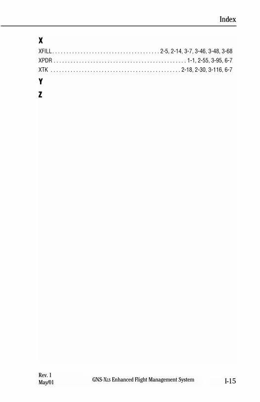
XXFILL . . . . . . . . . . . . . . . . . . . . . . . . . . . . . . . . . . . . . . 2-5, 2-14, 3-7, 3-46, 3-48, 3-68
XPDR . . . . . . . . . . . . . . . . . . . . . . . . . . . . . . . . . . . . . . . . . . . . . . . 1-1, 2-55, 3-95, 6-7
XTK . . . . . . . . . . . . . . . . . . . . . . . . . . . . . . . . . . . . . . . . . . . . . . 2-18, 2-30, 3-116, 6-7
Y
Z
Index
GNS-XLS Enhanced Flight Management System I-15Rev. 1May/01

Index
GNS-XLS Enhanced Flight Management SystemI-16Rev. 1
May/01
THIS PAGE INTENTIONALLY LEFT BLANK

N
Honeywell International Inc.One Technology Center23500 West 105th StreetOlathe, Kansas 66061FAX 913-791-1302Telephone: (913) 712-0400
006-18233-0000Rev. 3 Nov/04


