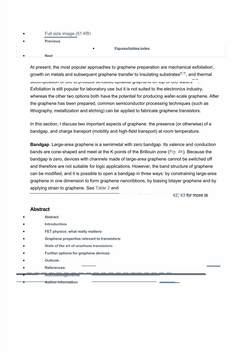
Graphene properties relevant to transistors • Abstract•• Introduction• • FET physics: what really matters•• Graphene properties relevant to transistors •• State of the art of graphene transistors•• Further options for graphene devices•• utloo!•• "eferences• • Ac!nowledgements •• Author information Single-layer graphene is a purely two-dimensional material. Its lattice consists of regular hexagons with a carbon atom at each corner. The bond length between adjacent carbon atoms, Lb, is .!" # and the lattice constant, a, is ".!$ # % &ig. !a'. The first reports on this material appeared decades ago, even before the name graphene had been coined %see, for example, (efs ), *, +', but it toothe pioneering "! paper by the anchester group to sparthe present explosion of interest in the material. Figure #: $roperties of graphene and graphene nanoribbons% a, Schematic of an armchair %ac' graphene nanoribbon %G/(' of length Lacand width Wac. The nanoribbon shown here has N0 + carbon atoms along its width and thus belongs to the 1 pfamily, where pis an integer. b, 2and structure around the 3 point of %i' large-area graphene, %ii' graphene nanoribbons, %iii' unbiased bilayer graphene, and %iv' bilayer graphene with an applied perpendicular field. 4arge-area graphene and unbiased bilayer graphene do not have a bandgap, which maes them less useful for digital electronics. c, 2andgap versus nanoribbon width from experiments "!,"5,"$,") and calculations "*,"+ .2y comparison, the bandgap of Si is above e6. 77 8 7ig7ag.
Transcript
7/18/2019 Graphene Properties Relevant to Transistors
9t present, the most popular approaches to graphene preparation are mechanical exfoliation,
growth on metals and subse:uent graphene transfer to insulating substrates", ", and thermal
decomposition of Si; to produce so-called epitaxial graphene on top of Si; wafers"", "1.
<xfoliation is still popular for laboratory use but it is not suited to the electronics industry,
whereas the other two options both have the potential for producing wafer-scale graphene. 9fter
the graphene has been prepared, common semiconductor processing techni:ues %such as
lithography, metalli7ation and etching' can be applied to fabricate graphene transistors.
In this section, I discuss two important aspects of graphene8 the presence %or otherwise' of abandgap, and charge transport %mobility and high-field transport' at room temperature.
)andgap. 4arge-area graphene is a semimetal with 7ero bandgap. Its valence and conduction
bands are cone-shaped and meet at the 3 points of the 2rillouin 7one %&ig. !b'. 2ecause the
bandgap is 7ero, devices with channels made of large-area graphene cannot be switched off
and therefore are not suitable for logic applications. =owever, the band structure of graphene
can be modified, and it is possible to open a bandgap in three ways8 by constraining large-area
graphene in one dimension to form graphene nanoribbons, by biasing bilayer graphene and by
Graphene has changed from being the exclusive domain of condensed-matter physicists to
being explored by those in the electron-device community. In particular, graphene-based
transistors have developed rapidly and are now considered an option for post-silicon
electronics. =owever, many details about the potential performance of graphene transistors in
real applications remain unclear. =ere I review the properties of graphene that are relevant to
electron devices, discuss the trade-offs among these properties and examine their effects on the
performance of graphene transistors in both logic and radiofre:uency applications. I conclude
that the excellent mobility of graphene may not, as is often assumed, be its most compelling
feature from a device perspective. (ather, it may be the possibility of maing devices with
channels that are extremely thin that will allow graphene field-effect transistors to be scaled to
shorter channel lengths and higher speeds without encountering the adverse short-channel
effects that restrict the performance of existing devices. >utstanding challenges for graphene
transistors include opening a si7eable and well-defined bandgap in graphene, maing large-
area graphene transistors that operate in the current-saturation regime and fabricating graphene
nanoribbons with well-defined widths and clean edges.
At a glance
)andgap. 4arge-area graphene is a semimetal with 7ero bandgap. Its valence and conduction
bands are cone-shaped and meet at the 3 points of the 2rillouin 7one %&ig. !b'. 2ecause the
bandgap is 7ero, devices with channels made of large-area graphene cannot be switched off
and therefore are not suitable for logic applications. =owever, the band structure of graphenecan be modified, and it is possible to open a bandgap in three ways8 by constraining large-area
graphene in one dimension to form graphene nanoribbons, by biasing bilayer graphene and by
=owever, it should be noted that real nanoribbons have rough edges and widths that change
along their lengths. <ven modest edge disorder obliterates any difference in the bandgap
between nanoribbons with different edge geometries"+, and edge functionali7ation and doping
can also affect the bandgap!!.
To open a bandgap useful for conventional field-effect devices, very narrow nanoribbons with
well-defined edges are needed. This represents a serious challenge given the semiconductor
processing e:uipment available at the moment. (ecently, nanoribbons that were uniform in
width and had reduced edge roughness were produced by @un7ipping@ carbon nanotubes!5.
=owever, even a perfect nanoribbon is not perfect for electronics applications. In general, the
larger the bandgap that opens in a nanoribbon, the more the valence and conduction bands
become parabolic %rather than cone-shaped'8 this decreases the curvature around the 3 point
and increases the effective mass of the charge carriers!$, which is liely to decrease the mobility.
2ilayer graphene is also gapless %&ig. !b', and its valence and conduction bands have a
parabolic shape near the 3 point. If an electric field is applied perpendicular to the bilayer, a
bandgap opens and the bands near the 3 point tae on the so-called exican-hat shape. This
opening was predicted by theory1, 1 and has been verified in experiments1", 11. Theoretical
investigations have also shown that the si7e of the bandgap depends on the strength of the
perpendicular field and can reach values of "A"5 me6 for high fields %%A1' B ) 6 cmC?
(efs 1,1'.
The bandgap of large-area single-layer epitaxial graphene is at present the subject of
controversy1!. 9lthough some results suggest a 7ero bandgap1), 1*, others report a bandgap of
around ."5 e6 %(efs 15, 1$'. The transfer characteristics of epitaxial-graphene >S&<Ts
show no switch-off, which suggests a 7ero bandgap. =owever, a bandgap is consistently
observed for epitaxial bilayer graphene1*, 1+.
&inally, strain has been discussed as a means of opening a bandgap in large-area graphene,
and the effect of uniaxial strain on the band structure has been simulated!, !. 9t present it
seems that if it is possible at all, opening a gap in this way will re:uire a global uniaxial strainexceeding "D, which will be difficult to achieve in practice. oreover, little is nown about the
ways in which other types of strain, such as biaxial strain and local strain, influence the band
Thus, although there are a number of techni:ues for opening a bandgap in graphene, they are
all at the moment some way from being suitable for use in real-world applications.
-obility. The most fre:uently stated advantage of graphene is its high carrier mobility at room
temperature. obilities of ,A5, cm" 6C sC are routinely measured for exfoliatedgraphene on Si>"-covered silicon wafers, !), and upper limits of between !, and ),
cm"6C sC have been suggested!), !*. oreover, in the absence of charged impurities and ripples,
mobilities of ", cm" 6C sC have been predicted!+, and a mobility of $ cm" 6C sC was
recently reported for suspended graphene5. &or large-area graphene grown on nicel and
transferred to a substrate, mobilities greater than 1,) cm" 6C sC have been measured".
&inally, for epitaxial graphene on silicon carbide, the mobility depends on whether the graphene
is grown on the silicon face or the carbon face of Si;. 9lthough graphene grown on the carbon
face has higher mobility %values of E5, cm" 6C sC have been reported"1, compared with
E, cm" 6C sC for graphene grown on the silicon face"1, 5', it is easier to grow single-layer
and bilayer graphene on the silicon face, which maes the silicon face of Si; more suited for
electronic applications.
In early graphene >S structures, the mobility was affected by the use of a top-gate
dielectric5",51. =owever, the recent demonstration of mobilities of around "1, cm" 6C sC in top-
gated graphene >S channels5! and the observation of similar mobilities before and after top-
gate formation55 show that high-mobility graphene >S channels can be made with a proper
choice of the gate dielectric and optimi7ation of the deposition process.
These mobility numbers are impressive, but they re:uire closer inspection. The high mobilities
mentioned above relate to large-area graphene, which is gapless. 9 general trend for
conventional semiconductors is that the electron mobility decreases as the bandgap increases,
and a similar trend has been predicted for carbon nanotubes %;/Ts'5$, 5) and graphene
nanoribbons5*, 5+, $,$ %&ig. 5a'. This means that the mobility in nanoribbons with a bandgap similar
to that of silicon %. e6' is expected to be lower than in bul silicon and no higher than the
mobility in the silicon channel of a conventional >S device5*. The mobilities measured inexperimentsFless than " cm" 6C sC for nanoribbons A nm wide"$, $" and ,5
cm" 6C sC for a nanoribbon ! nm wide!5 %which is the highest mobility so far measured for a
nanoribbon'Fsupport the theoretical results %&ig. 5b'. Therefore, although the high mobilities
offered by graphene can increase the speed of devices, they come at the expense of maing it
difficult to switch devices off, thus removing one of the main advantages of the ;>S
configurationFits low static power consumption.
Figure .: /arrier transport in graphene%
a, <lectron mobility versus bandgap in low electric fields for different materials, as indicated %from left to
right, III A6 compounds are InSb, In9s, In.51Ga.!) 9s, In, Ga9s, In.!+Ga.5, and Ga/'. The mobility data
relates to undoped material except for the Si >S data. 9lso shown are mobility data for carbon
nanotubes %;/Ts? simulation5$, 5)', graphene nanoribbons %simulation5*, 5+' and graphene %experiment and
simulation!), !*, !+, 5'. b, ;arrier mobility versus nanoribbon width at low electric fields from
simulations$, $ and experiments %open$" and full!5 stars'. Hata for large-area graphene are also
shown,!), !*. c, <lectron drift velocity versus electric field for common semiconductors %Si, Ga9s,
In.51Ga.!) 9s', a carbon nanotube %simulation5)' and large-area graphene %simulation$1, $!'.
• &ull si7e image %!5 32'
• $revious
• Figures&tables inde'
• (e't
0igh1field transport. In the days when &<Ts had gates several micrometres long, the mobility
was the appropriate measure of the speed of carrier transport. Strictly speaing, however, the
mobility describes carrier transport in low electric fields? the short gate lengths in modern &<Ts
result in high fields in a si7eable portion of the channel, reducing the relevance of mobility to
device performance. To illustrate this, let us consider a &<T with a gate nm long and a
drainAsource voltage of 6. If we assume a voltage drop of .1 6 across the series resistances,the average field in the channel is ) 6 cmC. 9t such high fields, the steady-state carrier
velocity saturates, and this saturation velocity becomes another important measure of carrier
transport. &igure 5cshows plots of the electron velocity versus the electric field for conventional
semiconductors, and simulated plots for large-area graphene$1, $! and a carbon nanotube5). &or
graphene and the nanotube, maximum carrier velocities of around ! B ) cm sC are predicted,
in comparison with " B ) cm sC for Ga9s and ) cm sC for silicon. oreover, at high fields the
velocity in graphene and the nanotube does not drop as drastically as in the III A
6 semiconductors. nfortunately, there is at present no experimental data available on high-field
transport in graphene nanoribbons and in large-area graphene. =owever, other
measurements$5 suggest high-field carrier velocities of several ) cm sC in graphene. Thus,
regarding high-field transport, graphene and nanotubes seem to have a slight advantage over
conventional semiconductors.
&inally, it is worth noting that reported mobilities for graphene devices need to be interpreted
carefully because there are several definitions for the >S&<T channel mobility and they are
difficult to compare$$. &urthermore, the techni:ues used to measure mobility are only vaguely
described in some papers. ost fre:uently, the field-effect mobility, μ &<, is measured %Table '.
=owever, the effect of the source and drain series resistances must be eliminated from the
measured characteristics to determine this :uantity, and it is not always clear that this has been
done.
9n additional complication lies in the interpretation of data from top-gated graphene >S&<Ts,
which involves arriving at a value for the gate capacitance, C G. &re:uently C G is approximated by
the oxide capacitance per unit area, as C ox 0 ε oxJt ox, where ε ox is the dielectric constant of the top-
gate dielectric and t ox is the thicness of this dielectric. =owever, when t ox is small, the :uantum
capacitance, C :, must be taen into account$), $* because it is connected in series withC ox, maing
the overall gate capacitance C G 0 C oxC :J%C ox K C :'. The overall gate capacitance can besignificantly smaller than C ox, particularly close to the Hirac point %the point of minimum drain
current', so neglecting the effect of C : will lead to an underestimate of the field-effect mobility.
&igure * shows the cut-off fre:uency for a variety of devices including graphene >S&<Ts,
nanotube &<Ts, and various radiofre:uency &<Ts. &or conventional radiofre:uency &<Ts with
gate lengths greater than ." Lm, the f T data for each transistor type has an LC dependence,
where L is the gate length. &urthermore, f T increases with mobility+. Silicon >S&<Ts show
channel mobilities of a few cm" 6C sC compared with about $, cm" 6C sC for Ga9s
p=<Ts and more than , cm" 6C sC for In =<Ts and Ga9s m=<Ts. 9t shorter gate
lengths, however, the mobility becomes less important for transistor speed and the deleterious
influence of parasitic resistances and short-channel effects increases. 2oth nanotube and
graphene &<Ts are still slower than the best conventional radiofre:uency &<Ts, but they have
recently overtaen the best silicon >S&<Ts with gate lengths above " nm and are
approaching the performance of Ga9s p=<Ts. %See ref. )* for details of the nanotube with the
9lthough the low onAoff ratios demonstrated so far mae use in logic devices unrealistic,
transistors with large-area graphene channels are promising candidates for radiofre:uency
applications because radiofre:uency &<Ts are not re:uired to switch off and can benefit from
the high mobilities offered by large-area graphene. =owever, the absence of drain-current
saturation will limit the radiofre:uency performance of graphene transistors.
>ne method of introducing a bandgap into graphene for logic applications is to create graphene
nanoribbons. /anoribbon >S&<Ts with bac-gate control and widths down to less than 5 nm
have been operated as p-channel devices and had onAoff ratios of up to $ %(efs "$, $"'. Such
high ratios have been obtained despite simulations showing that edge disorder leads to an
undesirable decrease in the on-currents and a simultaneous increase in the off-current of
nanoribbon >S&<Ts*, *.This, and other evidence of a si7eable bandgap opening in narrow
nanoribbons, provides proof of the suitability of nanoribbon &<Ts for logic applications.
=owever, these devices had relatively thic bac-gate oxides, so voltage swings of several volts
were needed for switching, which is significantly more than the swings of 6 and less needed
to switch Si ;>S devices". &urthermore, ;>S logic re:uires both n-channel and p-channel
&<Ts with well-controlled threshold voltages, and graphene &<Ts with all these properties have
not yet been reported.
(ecently, the first graphene nanoribbon >S&<Ts with top-gate control have been reported*".
These transistors feature a thin high-dielectric-constant %high-k ' top-gate dielectric %A" nm of
=f>"', a room-temperature onAoff ratio of ) and an outstanding transconductance of 1." mSLmC %which is higher than the transconductances reported for state-of-the-art silicon >S&<Ts
andIII A6 =<Ts'.
Graphene bilayer >S&<Ts have been investigated experimentally*1 and by device simulation*!.
9lthough the onAoff ratios reported so far % at room temperature and ", at low
temperature*1' are too small for logic applications, they mar a significant improvement %of about
a factor of ' over >S&<Ts in which the channel is made of large-area gapless graphene.
The contact resistance between the metallic source and drain contacts and the graphenechannel should be briefly mentioned. So far, the lowest reported metalAgraphene contact
resistances are in the range 5A, M cm %(efs *5,*$', which is about ten times the contact
resistance of silicon >S&<Ts and III A6 =<Ts*, 1. (emarably, in spite of the importance of the
contacts %particularly for short-channel devices', only a few studies dealing with metalAgraphene
contacts have been published*5, *$, *) and more wor is needed to understand the contact
properties.
I now return to the two-dimensional nature of graphene. 9ccording to scaling theory, as noted
previously, a thin channel region allows short-channel effects to be suppressed and thus maesit feasible to scale >S&<Ts to very short gate lengths. The two-dimensional nature of
graphene means it offers us the thinnest possible channel, so graphene >S&<Ts should be
more scalable than their competitors. It should be noted, however, that scaling theory is valid
only for transistors with a semiconducting channel and does not apply to graphene >S&<Ts
with gapless channels. Thus, the scaling theory does describe nanoribbon >S&<Ts, which
have a bandgap but which have significantly lower mobilities than large-area graphene, as
discussed. Given that the high published values of mobility relate to gapless large-area
graphene, the most attractive characteristic of graphene for use in >S&<Ts, in particular those
re:uired to switch off, may be its ability to scale to shorter channels and higher speeds, rather


![Synthesis and Biomedical Applications of Graphene: Present ... · applications in many areas, such as graphene electronic transistors [18, 19], integrated circuits [20], transparent](https://static.documents.pub/doc/80x56/5f02df157e708231d4066cce/synthesis-and-biomedical-applications-of-graphene-present-applications-in-many.jpg)
