73
ISE 2.0 Wireless Guest Setup Guide Secure Access How -To Guides Series Author: Jason Kunst Date: March 2016

ISE 2.0 Wireless Guest Setup Guide Secure Access How -To Guides Series
Author: Jason Kunst
Date: March 2016
Cisco Systems © 2016 Page 2
SECURE ACCESS HOW-TO GUIDES
Table of Contents About This Guide ...................................................................................................................................................... 4
How Do I Get Support? ...................................................................................................................... 4 Using This Guide .................................................................................................................................. 4 Requirements ........................................................................................................................................ 7
Guest Access ............................................................................................................................................................. 8 Guest Access with Hotspot Guest Portals ................................................................................... 8 Guest Access with Credentialed Guest Portals .......................................................................... 8
Download Cisco ISE Software ............................................................................................................................ 9
Planning...................................................................................................................................................................... 11 Pre-setup Checklist ........................................................................................................................... 11
Installation and Setup of Cisco ISE on a VMware Server ...................................................................... 13 Deploy ISE OVA as a Virtual Machine ........................................................................................ 14 Run ISE Setup .................................................................................................................................... 14 Install the ISE Patch .......................................................................................................................... 15
Configure WLC Basics ......................................................................................................................................... 16 Connect to WLC ................................................................................................................................. 17
Set Up Your Controller ............................................................................................................... 17 Create Your Wireless Networks .............................................................................................. 19 Connect WLC to Your Network ............................................................................................... 20
Assisted WLC & ISE Configuration with Setup Wizard .......................................................................... 22
Configuring the WLC for ISE Web Authentication ................................................................................... 33 Captive Portal Bypass Configuration ........................................................................................... 34 Configure the RADIUS Authentication Server on WLC ......................................................... 34 Configure the RADIUS Accounting Server on WLC................................................................ 35 Change WLAN Configuration to use ISE Web Authentication ............................................. 36 Configure ACLs for Guest Redirection and Permit Access .................................................. 40
Configure an ACL to Redirect Guest Devices to ISE Guest Portal .............................. 40 Configure an ACL to Permit Guest Access to the Internet After Authenticated ....... 41
Configure ISE for Guest Access ...................................................................................................................... 42 Configure the Wireless Controller (WLC) as a Network Access Device (NAD) ............. 43 Authentication Policy Setup ............................................................................................................ 44

Cisco Systems © 2016 Page 3
SECURE ACCESS HOW-TO GUIDES
Create an Authorization Profile to Redirect Guest Endpoints to ISE ................................. 44 Create an Authorization Profile to Permit Access .................................................................... 45 Create Authorization Policies for Guest Access ....................................................................... 46
Configure Minimum Settings for Self-Registration and Sponsored Guest Flows ...................... 50 Configure Guest Locations and Time Zones ............................................................................. 50 Configure the Portal to Use the Location (Self-Registration) ............................................... 51
Configure Required Settings for Sponsored Guest Flow ..................................................................... 52 Working with Sponsor Accounts .................................................................................................... 52 Using Sponsor Accounts from Active Directory ........................................................................ 52 Set up the Active Directory Sponsor Group in All_Accounts ................................................ 55 Configure Locations for Your Sponsor Group ........................................................................... 55 Setup ISE Sponsor Portal FQDN Based Access ..................................................................... 56
Configure Basic Portal Customization (Optional) .................................................................................... 58
Setting up a Well-known Certificate (Optional) ......................................................................................... 61 Create a Certificate Signing Request and Submit the CSR to a Certificate Authority .. 61 Import Certificates to the Trusted Certificate Store ................................................................. 63 Bind the CA-Signed Certificate to the Signing Request ......................................................... 64
Setting Changes for Admin & Guest Accounts (Optional) ................................................................... 66 Get Acquainted with the Administrator Password Policy ....................................................... 66 Change Guest Account Requirements ........................................................................................ 66
What’s Next ............................................................................................................................................................... 68
Appendix A – Wireless Configuration ........................................................................................................... 69
Appendix B – Switch Configuration ............................................................................................................... 72
Cisco Systems © 2016 Page 4
SECURE ACCESS HOW-TO GUIDES
About This Guide This guide describes the express process for configuring Cisco Identity Services Engine (ISE) with a Cisco Wireless Controller to provide Guest Access. Using the steps in this guide, you can set up guest access for your users in approximately two hours.
Some aspects of this guide can be used for a WLC or ISE that has already been set up. This guide’s flow requires you to have a physical controller that has been reset (no config) and ISE web UI available so that we may step you through basic setup in the correct order.
This guide is most helpful for those that have bought ISE Express (an inexpensive license for WLC/ISE), but maybe used by anyone that wants to configure the ISE and WLC from a clean install.
This guide is for ISE 2.0.
There are two types of portals supported by this guide:
• Guest Access with Hotspot Guest Portals • Guest Access with Credentialed Guest Portals
How Do I Get Support? For general support ISE Guest and wireless, please contact your local Cisco partner, account team, ISE Support community or the Cisco TAC.
For questions around the licensing bundle known as ISE Express or specific issues with the ISE Wireless Guest Setup Guide or Wizard please email [email protected]
Using This Guide This guide has two parts that describe the activity required to install and configure Wireless Guest access using ISE and a Cisco Wireless Controller (WLC).
Cisco Systems © 2016 Page 5
SECURE ACCESS HOW-TO GUIDES
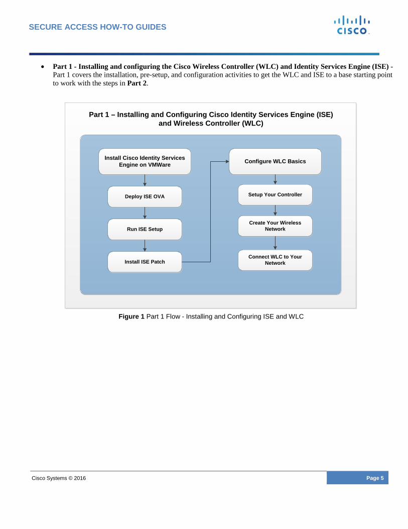
• Part 1 - Installing and configuring the Cisco Wireless Controller (WLC) and Identity Services Engine (ISE) - Part 1 covers the installation, pre-setup, and configuration activities to get the WLC and ISE to a base starting point to work with the steps in Part 2.
Figure 1 Part 1 Flow - Installing and Configuring ISE and WLC
Part 1 – Installing and Configuring Cisco Identity Services Engine (ISE)and Wireless Controller (WLC)
Install Cisco Identity Services Engine on VMWare
Install ISE Patch
Deploy ISE OVA
Run ISE Setup
Configure WLC Basics
Connect WLC to Your Network
Setup Your Controller
Create Your Wireless Network

Cisco Systems © 2016 Page 6
SECURE ACCESS HOW-TO GUIDES
• Part 2 - Configuring the WLC and ISE for Guest Access - Part 2 covers the additional configuration steps for
Cisco Wireless Guest Access with ISE.
Part 2 – Configuring WLC and ISE for Guest Services
Configure WLC for ISE Web Authentication
Configure Minimum Settingsfor Self-Registration
(Optional)
Configure Required Settingsfor Sponsored Guest Flows
(Optional)
Set Up a Well-known Certificate(Optional)
Configure Basic Portal Customization
(Optional)
Configure ISE for Guest Services
Set Changes for Admin and Guest Accounts
(Optional)
Assisted WLC/ISE Configuration with ISE Express Wizard
(Optional)
What’s Next

Cisco Systems © 2016 Page 7
SECURE ACCESS HOW-TO GUIDES
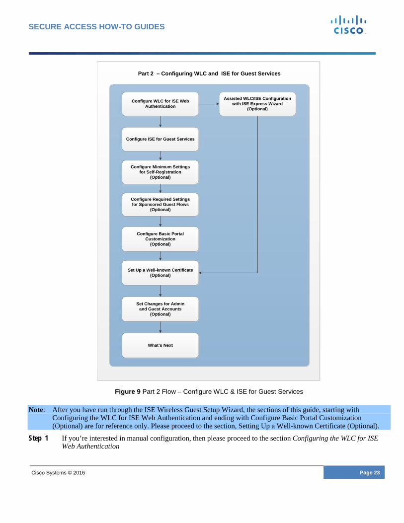
Figure 2 Part 2 Flow - Configuring WLC and ISE for Guest Services
Requirements • Supported Virtual Environments
o VMware version 8 (default) for ESX (i) 5.x o VMware version 11 (default) for ESX (i) 6.x o KVM on RHEL 7.0 (supported but not covered in this guide)
• Virtual machine running as a SNS-3415 appliance – see Table 2 of VMware Appliance Specifications • Cisco Identity Services Engine Release 2.0 with latest patch
• Physical Cisco Wireless controller (WLC) running 8.0.121.0. For latest info reference the ISE compatibility chart.
o We recommend, if you’re not already running this code to upgrade after you complete the setup of the solution.
• For Sponsor Groups from Microsoft Active Directory, verify Supported External Identity Sources section of the ISE Network Component Compatibility Guide.
Note: This guide is for a new Wireless Controller installation only. If this not a new installation, then perform a factory reset of the controller. Refer to the controller documentation for steps to reset the controller. If you still want to use the guide, then you can use it as a reference for configuration of the needed WLAN and ACL configurations.

Cisco Systems © 2016 Page 8
SECURE ACCESS HOW-TO GUIDES
Guest Access When people outside your company attempt to use your company’s network to access the Internet or resources and services on your network, you can provide them network access using Guest Access portals. Guests typically represent authorized visitors, contractors, customers, or other temporary users who require access to your network.
There are two types of Guest Access portals supported by this guide:
• Guest Access with Hotspot Guest Portals • Guest Access with Credentialed Guest Portals
Guest Access with Hotspot Guest Portals The Guest Access with Hotspot Guest portal provides network access without requiring guests to establish usernames and passwords to connect. This type of Guest Access eliminates the overhead required to manage each individual guest account. When the guest connects to the network, they are redirected to the ISE Hotspot Guest portal where they must accept an Acceptable Use Policy (AUP) to gain access to the network and eventually the Internet.
Guest Access with Credentialed Guest Portals The Credentialed Guest portal requires guests to have a username and password to gain access. Using a self-registration portal, the guest can create their own account to use to login to the Guest Portal. The self-registration portal can also be used along with credentials created by a Sponsor. A Sponsor can be an employee or lobby ambassador, for example. When the guest connects to the network, they are redirected to a portal that allows them to login with credentials created through self-registration or provided by a sponsor. After guests log in, they can be required to accept an Acceptable Use Policy (AUP) to gain access to the network. You can also set up access using a Sponsored Guest Portal, which requires users to have credentials created by a Sponsor.
For more information about guest portals and features, refer to Cisco Guest Access.

Cisco Systems © 2016 Page 9
SECURE ACCESS HOW-TO GUIDES
Download Cisco ISE Software Download the latest Cisco ISE software and ISE patches using the ISE software download link.
Software Download Click Cisco ISE Download Software to access the Cisco ISE software download page where you can download the following files:
• ISE VM OVA File of ISE 2.0: Virtual SNS-3415
ISE-2.0.0.306-virtual-SNS3415.ova
• ISE 2.0 latest patch – for more info on this release, please reference the release notes
Example: ise-patchbundle-2.0.0.306-Patch2-164765.SPA.x86_64.tar.gz
• ISE 2.0 Wireless Guest Setup Wizard (Recommended for automated configuration of WLC & ISE) o Supported on:
Apple MAC OSX 10.9 and higher Microsoft Windows 7 and higher
Note: When downloading the ISE Patch (tar.gz), some web browsers, such as OSX Safari, do not maintain the archive structure. You must maintain the archive structure when installing a patch, so we recommend using the Firefox or Google Chrome browsers.
You can view a video about downloading Cisco ISE software by clicking the link below:
• Introduction to ISE and how to download Cisco ISE software

Cisco Systems © 2016 Page 10
SECURE ACCESS HOW-TO GUIDES

Cisco Systems © 2016 Page 11
SECURE ACCESS HOW-TO GUIDES
Planning Before you start installing and configuring ISE and the WLC, we recommend that you spend some time collecting information that you use during installation and configuration. We created a checklist you can use to help organize and record server information. Refer to this checklist as needed during the installation and configuration processes.
Note: Before installing ISE, and while you are recording the Pre-setup Checklist information, make sure you have access to the following services. If these services are not available, the installation process may fail.
• DNS (Internal Server ) • NTP and default gateway
Verify the time is correct on your ESX and NTP hosts. Host times must to be synchronized for services and certificates to work correctly.
Pre-setup Checklist Table 1 Pre-Setup Checklist
No. Services Description Record info here
1 WLC System Name • Name of the controller system • Configured on WLC • Example: WLC
WLC System Name: _________________________
2 Wireless Controller IP, Subnet Mask and Gateway
• Network information for the WLC • Configured on WLC & ISE
Wireless Controller IP: _____________________
Subnet Mask: __________________________________
Gateway: _______________________________
3 DHCP Server IP • DHCP Server in the network • Configured on WLC
DHCP Server IP: _________________________
4 Guest SSID • The network name your guests will access
• Configured on WLC • Example: yourcompany-guest
Guest SSID: ____________________________
5 Guest VLAN (optional)
If you are using the same network for guests as management network then this is not needed
• The VLAN used for Guests • Configured on WLC • Example: 50
Guest VLAN: ____________________________

Cisco Systems © 2016 Page 12
SECURE ACCESS HOW-TO GUIDES
6 Guest Network IP Address, Subnet Mask, and Gateway
• Controller needs an IP address on your Guest Network to talk to your guests
• Configured on WLC
Guest Network IP: _____________________
Subnet Mask: __________________________________
Gateway: _______________________________
7 DNS Server IP • DNS Server in the network • Configured on ISE
DNS Server IP: __________________________
8 NTP Server IP • NTP Server in the network • Configured on ISE
NTP Server IP: __________________________
9 ISE IP, Subnet Mask and Gateway
• Network Information for ISE • Configured on WLC & ISE
ISE IP: ______________________
Subnet Mask: _________________________
Gateway: __________________
10 ISE Hostname & Domain • Name and domain of your ISE Server
• Configured on ISE • Needs to be in DNS otherwise
this solution won’t work
ISE Hostname: __________________________
ISE Domain: ____________________________
11 Management Network VLAN
• The network that ISE & WLC will connect to on ESX (i) host
• Configured on WLC & ESX(i) host
• Example: 100
Mgmt. Network VLAN: __________________
12 Shared Secret • This is a password that will be shared between ISE and WLC for communications to secure the RADIUS channel.
• Configured on WLC & ISE
Shared Secret: ____________________________

Cisco Systems © 2016 Page 13
SECURE ACCESS HOW-TO GUIDES
Installation and Setup of Cisco ISE on a VMware Server This part of the guide describes the tasks for installing and setting up ISE software on a VMware server.
Figure 3 shows the workflow tasks in this part of the guide. This workflow represents the tasks that must be completed for a successful Guest Services deployment using ISE.
Figure 3 Part 1 Flow – Install Cisco ISE on WMWare
Part 1 – Installing and Configuring Cisco Identity Services Engine (ISE)and Wireless Controller (WLC)
Install Cisco Identity Services Engine on VMWare
Install ISE Patch
Deploy ISE OVA
Run ISE Setup
Configure WLC Basics
Connect WLC to Your Network
Setup Your Controller
Create Your Wireless Network

Cisco Systems © 2016 Page 14
SECURE ACCESS HOW-TO GUIDES
Deploy ISE OVA as a Virtual Machine You can use OVA templates to install and deploy Cisco ISE software on a virtual machine. In the previous task Download Cisco ISE Software you downloaded the OVA template from Cisco.com.
To deploy an ISE OVA in your ESX(i) environment:
Step 1 Open VMware vSphere client. Step 2 Log in to VMware host. Step 3 Choose File > Deploy OVF Template from the VMware vSphere Client. Step 4 Click Browse to select the OVA template and click Next. Step 5 Confirm the details in the OVF Template Details page and click Next. Step 6 Enter a name for the virtual machine in the Name and Location page to uniquely identify it and click Next. Step 7 Choose a data store to host the OVA. Step 8 Click the Thick Provision radio button on the Disk Format page, and click Next.
o Cisco ISE supports both thick and thin provisioning. However, we recommend that you choose thick provisioning for better performance. If you choose thin provisioning, operations such as upgrade, backup and restore, and debug logging that require more disk space might be impacted during initial disk expansion.
Note: If you are asked to select Lazy or Eager Zeroed, select Lazy.
Step 9 Verify the information in the Ready to Complete page. Step 10 Check the Power on after deployment check box. Step 11 Click Finish.
Run ISE Setup In this section, you set up your ISE Virtual Machine using the VSphere Console Common-line Interface (CLI). When the installation process finishes, the virtual machine reboots automatically. When the Virtual Machine reboots, you will see the system prompt.
Step 1 At the system prompt, enter setup and press Enter.
o The Setup Wizard appears and guides you through the initial configuration.
Step 2 Use the information you gathered in the Pre-setup Checklist section of this document to answer the questions form the Setup Wizard.
o This example shows a sample output of the setup command.
localhost login: setup Press 'Ctrl-C' to abort setup Enter hostname[]: ise Enter IP address[]: 10.1.100.22 Enter IP default netmask[]: 255.255.255.0 Enter IP default gateway[]: 10.1.100.1 Enter default DNS domain[]: yourdomain.com Enter primary nameserver[]: 172.16.168.183 Add/Edit another nameserver? Y/N : n Enter primary NTP server[time.nist.gov]:

Cisco Systems © 2016 Page 15
SECURE ACCESS HOW-TO GUIDES
Add/Edit secondary NTP server? Y/N : n Enter system timezone[UTC] : Enter username[admin]: Enter password: Enter password again: Bringing up network interface... Pinging the gateway... Pinging the primary nameserver... Do not use 'Ctrl-C' from this point on... Appliance is configured
o For more information and details about the installation, please reference the Cisco ISE 2.0 Administration Guide section, Installing Cisco ISE Software on a VMware System.
Install the ISE Patch After you set up the ISE Virtual Machine is up and running, use these instructions to install the latest patch.
Step 1 Login to the ISE Admin UI at (http://iseapaddress) Step 2 Navigate to Administration > System > Maintenance > Patch Management > Install. Step 3 Click Browse and choose the patch that you downloaded from Cisco.com. Step 4 Click Install to install the patch.
o After the patch is installed, Cisco ISE logs you out and you must wait for a few minutes before you can log in again.
Note: When patch installation is in progress, Show Node Status is the only function that is accessible on the Patch Management page
Step 5 Navigate to Administration > System > Maintenance > Patch Management to return to the Patch Installation page.
For more information on ISE patches reference Cisco ISE 2.0 Administration Guide section on Installing a Software Patch

Cisco Systems © 2016 Page 16
SECURE ACCESS HOW-TO GUIDES
Configure WLC Basics There are multiple ways one can configure the Cisco Wireless LAN Controller. In this guide we are using the WLAN Express Setup. For more information on the WLAN Express setup and the WLC configuration, select one of the following links:
• WLAN Express Setup Video • Cisco WLAN Release Notes
The flow diagram shown in Figure 4 shows the process to use when Configuring WLC Basics.
Figure 4 Part 1 Flow - Configure WLC Basics
Part 1 – Installing and Configuring Cisco Identity Services Engine (ISE)and Wireless Controller (WLC)
Install Cisco Identity Services Engine on VMWare
Install ISE Patch
Deploy ISE OVA
Run ISE Setup
Configure WLC Basics
Connect WLC to Your Network
Setup Your Controller
Create Your Wireless Network

Cisco Systems © 2016 Page 17
SECURE ACCESS HOW-TO GUIDES
Connect to WLC Before connecting all the components to configure Cisco wireless Guest Services, first establish communication between your laptop (computer) and the WLC. After you establish the initial communication between your laptop and the WLC, you can complete the hardware setup and software installation procedures.
Set Up Your Controller To connect to the WLC perform the following steps:
Step 1 Connect your admin laptop to Port 2 on the WLC as shown in Figure 5.
Figure 5 Connect Laptop to WLC
o The laptop should get an IP address from subnet 192.168.1.0/24.
Step 2 Open a web browser and enter 192.168.1.1 to access the WLC Setup Wizard.
o The WLC Setup user interface displays as shown in Figure 6.

Cisco Systems © 2016 Page 18
SECURE ACCESS HOW-TO GUIDES
Figure 6 Set Up Your Controller
Step 3 Enter the credentials used to manage the controller. Refer to the Pre-Setup Checklist you completed in the Planning section.
Table 2 Setup Your Controller Fields
Field Description
System Name WLC System Name
Pre-checklist item number - 1
Country Your current country location
Date & Time Your current date and time
Timezone Select Timezone from the drop-down menu
NTP Server IP address for the NTP server
Pre-checklist item number - 8
Management IP Address IP address for managing the wireless controller
Pre-checklist item number - 2

Cisco Systems © 2016 Page 19
SECURE ACCESS HOW-TO GUIDES
Field Description
Subnet Mask Subnet Mask for the WLC
Pre-checklist item number - 2
Default Gateway Default Gateway for the WLC
Pre-checklist item number - 2
Management Network VLAN Management Network VLAN
Pre-checklist item number - 11
Step 4 Click Next to continue.
o Next, create Your Wireless Networks.
Create Your Wireless Networks Step 5 Click the X to deselect the Employee Network.
Note: Setting up a wireless dot1x network for employees (internal users) is not covered in this guide.
Step 6 Click the checkmark next to Guest Network, as shown in Figure 7:
Figure 7 Create Your Wireless Network

Cisco Systems © 2016 Page 20
SECURE ACCESS HOW-TO GUIDES
Table 3 Create your Wireless Networks Fields
Field Description
Network Name Wireless Network (SSID) for your Guests
Prechecklist item number - 4
Security Select the security type ‘Web Consent’ from options listed in the drop-down menu.
Note: WPA is not supported for ISE Guest.
VLAN Select the VLAN ‘New VLAN’ from the options listed in the drop-down menu
VLAN IP Address IP address for your guest network
Prechecklist item number - 6
VLAN Subnet Mask IP address for VLAN Sub Mask
Prechecklist item number - 6
VLAN Default Gateway IP address for default gateway
Prechecklist item number - 6
VLAN ID (optional) ID for VLAN (optional, if using management network, this is not needed)
Prechecklist item number - 5
DHCP Server Address IP address for your DHCP server
Prechecklist item number - 3
Step 7 Enter the information required from the Pre-setup Checklist. Step 8 Click Next to continue.
o A confirmation screen displays with a message asking if you want to apply the WLC confirmation changes and informs you that your system will reboot after you click OK.
Connect WLC to Your Network To better explain the scenarios and configurations listed in this document, look at the sample topology in Figure 8

Cisco Systems © 2016 Page 21
SECURE ACCESS HOW-TO GUIDES
Figure 8 Sample Topology
The Cisco 3560G switch in the Figure 8 Sample Topology provides basic connectivity to all the components. Configure all the ports on the switch for access VLAN 100, except Port 10, which must be configured as a Trunk port.
Refer to Appendix A – Switch Configuration for more details on switch configuration.
Note: After the WLC reboots the management function is now live on VLAN 100 (example 10.1.100.42) and will no longer respond via the old IP address.
Step 1 Disconnect the admin laptop from Port 2 on the WLC and connect it instead to Port 1 on the switch. Step 2 Connect Port 1 on the WLC to the Trunk Port 10 on the switch. Your Switch trunkport should contain the
Management VLAN (100) and Guest VLAN (50) in order to manage the controller and to provide guest access
o You should be able to again access the WLC using the admin PC. (Example: https://10.1.100.42).
Step 3 Setup your network for your access point discovery of the controller.
To set up your access point, configure your network to discover the wireless controller. For more information about setting up discovery options in your network, please refer to the Wireless Controller documentation:
http://www.cisco.com/c/en/us/td/docs/wireless/controller/8-0/configuration-guide/b_cg80/b_cg80_chapter_01100101.html#ID302
Step 4 After you have setup the necessary discover option in your network, connect your Access Point to Port 8
Note: At this point, you should be able to see your Guest Wireless Network (SSID) from any client (Pre-Setup Checklist #4). This is a basic splash page from the controller and its not yet integrated to use the ISE Guest (Web Auth) Portals.

Cisco Systems © 2016 Page 22
SECURE ACCESS HOW-TO GUIDES
Assisted WLC & ISE Configuration with Setup Wizard Now that you have completed the basic installation and setup of the WLC and ISE, you have two options on how to proceed with the rest of the configuration.
The recommended path is to use the ISE 2.0 Wireless Guest Setup Wizard to automate this task. The wizard runs on OS X and Windows. It will ask you the information required to connect and configure your system for your required Guest Flow.
You should have previously downloaded Wizard. If not, download it here Cisco ISE Download Software.
By using the wizard, you bypass most of the guide as seen in Figure 9.
Cisco Systems © 2016 Page 23
SECURE ACCESS HOW-TO GUIDES
Figure 9 Part 2 Flow – Configure WLC & ISE for Guest Services
Note: After you have run through the ISE Wireless Guest Setup Wizard, the sections of this guide, starting with Configuring the WLC for ISE Web Authentication and ending with Configure Basic Portal Customization (Optional) are for reference only. Please proceed to the section, Setting Up a Well-known Certificate (Optional).
Step 1 If you’re interested in manual configuration, then please proceed to the section Configuring the WLC for ISE Web Authentication
Part 2 – Configuring WLC and ISE for Guest Services
Configure WLC for ISE Web Authentication
Configure Minimum Settingsfor Self-Registration
(Optional)
Configure Required Settingsfor Sponsored Guest Flows
(Optional)
Set Up a Well-known Certificate(Optional)
Configure Basic Portal Customization
(Optional)
Configure ISE for Guest Services
Set Changes for Admin and Guest Accounts
(Optional)
Assisted WLC/ISE Configuration with ISE Express Wizard
(Optional)
What’s Next

Cisco Systems © 2016 Page 24
SECURE ACCESS HOW-TO GUIDES
In Figure 10, the wizard lists the basic requirements before starting. It has a Debug Window option in the bottom left if you need to provide logs to the developers. In the bottom right you will notice the build #.
Figure 10 ISE Wireless Guest Setup Wizard Launch
Step 2 Click Start.
In Figure 8, choose the Portal Type (Guest Flow) you would like to send your guests through. These flows were explained earlier on in the section Guest Access. You can also select if you would like to customize your portal.
Step 3 Check the box to enable portal customization (optional), and select the Guest Flow you would like to use. Skip to Step 5 if you don’t want to work with customization at this time. You can configure your portals later. See the section Configure Basic Portal Customization (Optional) for more information.

Cisco Systems © 2016 Page 25
SECURE ACCESS HOW-TO GUIDES
Figure 11 Select Portal Type
Step 4 Upload your logo, banner and choose your color theme as seen in Figure 12 and click Next.
Note: This customization will be made to any of portal in your flow (Guest or Sponsor).

Cisco Systems © 2016 Page 26
SECURE ACCESS HOW-TO GUIDES
Figure 12 Portal Customization
Step 5 Fill in the information required to configure your wireless controller. You gathered this information during the
Planning phase using the Pre-setup Checklist. When complete, click Next.
Note: The Gateway IP address is the default gateway of your WLC management network

Cisco Systems © 2016 Page 27
SECURE ACCESS HOW-TO GUIDES
Figure 13 Configure your WLC
Step 6 The wizard will now connect to your wireless controller to get a list of available WLANs. Choose the Guest network that you configured when running through WLAN Express and click Next.
Figure 14 Select WLAN
Step 7 In Figure 15, the wizard will ask you for the necessary information in order to configure your ISE. This information was gathered using the Pre-setup Checklist. After you have entered the necessary information, click Next. Guest Location/Time Zone - It’s critical that you enter the correct time zone of your guests. For more information, or to configure more locations after the wizard has completed, reference the section Configure Guest Locations and Time Zones Choose your Sponsor Source - There is also an option to choose what identity source to use for your Sponsors. Here we show the option to use groups from your Active Directory. You can also choose to create a local user on ISE. For more information about these options, or to add another sponsor once the wizard has completed setup, reference the section Working with Sponsor Accounts.
Note: Here we are showing the Sponsored Guest Flow using Active Directory group, since that’s a superset (and the most detailed) of the options that you will see when going through the wizard.
In the Hotspot flow, you will not see any of these options, and the self-registration flow will not have the option to configure the Sponsor User Source.

Cisco Systems © 2016 Page 28
SECURE ACCESS HOW-TO GUIDES
Figure 15 Configure your ISE
Step 8 Depending on the option you chose in Step 7, you will either see a screen to configure a Sponsor Account or point to your Active Directory. Since the local account is a simple procedure, we won’t highlight that option. If you chose to use local accounts, then skip to Step 10. If you chose to go with the Active Directory option as shown in Figure 16, please enter the information listed below and then click Next. The information here is simple. Enter the following:
• Join Point Name: a basic label for your domain connection built on ISE • Active Directory Domain: domain where your groups to use as sponsors reside • AD Username/Password

Cisco Systems © 2016 Page 29
SECURE ACCESS HOW-TO GUIDES
Figure 16 Active Directory Settings
Step 9 The wizard connects to your domain, and pulls down all the groups in your Active Directory. You may choose one or more groups that can access Sponsor Guests Accounts. After you have selected your accounts, click Next.

Cisco Systems © 2016 Page 30
SECURE ACCESS HOW-TO GUIDES
Figure 17 Select Groups
Step 10 This step configures an easy URL for the sponsor portal. There are some dependencies on DNS to use this feature. Even if you haven’t setup your DNS, you can still configure this option now and setup your DNS later. For more information please refer to the section, Setup ISE Sponsor Portal FQDN Based Access. Either enter your FQDN or choose the option to do this at a later time. Click Start
Figure 18 Configure Sponsor Portal FQDN
Support for Apple Devices requires a special configuration that requires a reboot. For more information on this option, see the section Captive Portal Bypass Configuration.
Cisco Systems © 2016 Page 31
SECURE ACCESS HOW-TO GUIDES
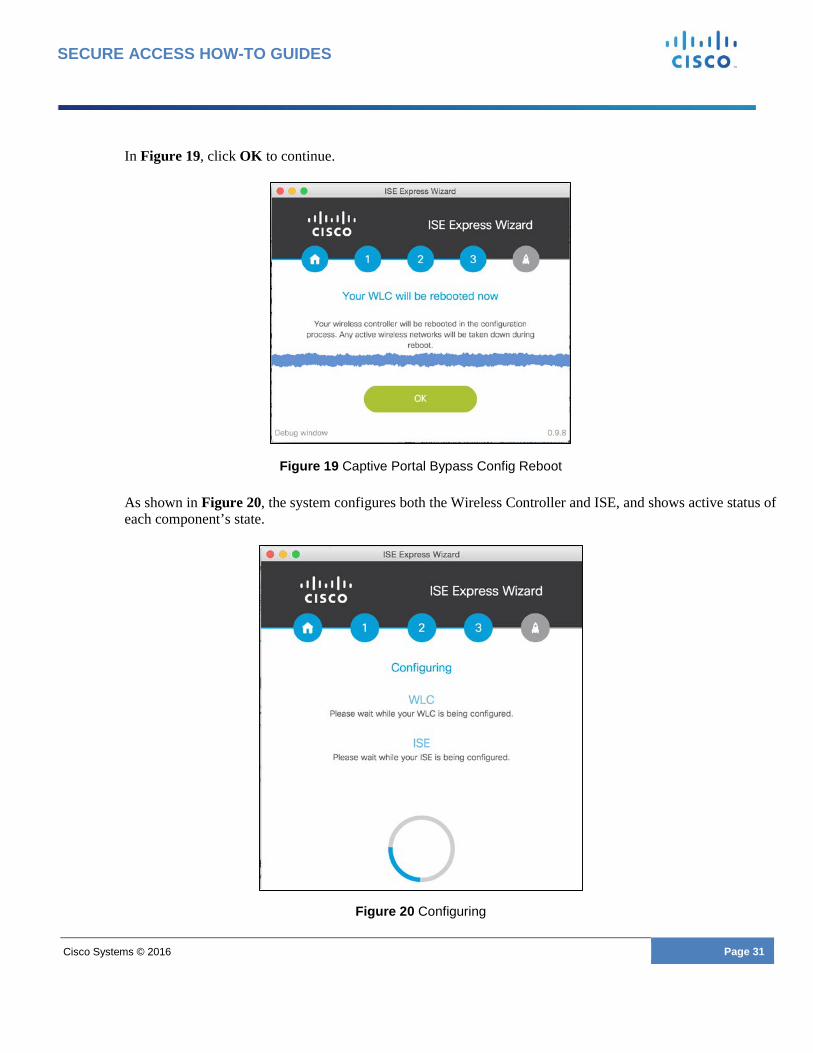
In Figure 19, click OK to continue.
Figure 19 Captive Portal Bypass Config Reboot
As shown in Figure 20, the system configures both the Wireless Controller and ISE, and shows active status of each component’s state.
Figure 20 Configuring

Cisco Systems © 2016 Page 32
SECURE ACCESS HOW-TO GUIDES
After the wizard configures the WLC and ISE, you will see a final status screen as seen in Figure 21. This screen provides you with the following information:
• SSID: Name that a client will connect to. • Link to your guest portal. You can use this to see what the portal looks like. It can also be used to test
the portal completely, like a user would see from a real device. • For Sponsored flow, it provides a link to the Sponsor Portal and also the easy URL (FQDN), when
configured.
Figure 21 Configuration Completed
Step 11 Click Close.
Note: Now that your system configuration has been completed, this tool can no longer be used to connect to your WLC or ISE unless you were to reset the configuration on both and start new. If you need to change any of the configurations or learn about the system as a whole, you can read through the rest of the document.
Now that you have completed setup using the wizard, note that the following sections, starting with Configuring the WLC for ISE Web Authentication and ending with Configure Basic Portal Customization (Optional), are for reference only. Please proceed to the section Setting Up a Well-known Certificate (Optional).
Cisco Systems © 2016 Page 33
SECURE ACCESS HOW-TO GUIDES
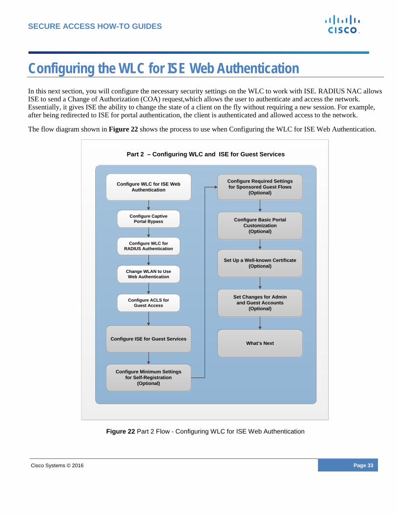
Configuring the WLC for ISE Web Authentication In this next section, you will configure the necessary security settings on the WLC to work with ISE. RADIUS NAC allows ISE to send a Change of Authorization (COA) request,which allows the user to authenticate and access the network. Essentially, it gives ISE the ability to change the state of a client on the fly without requiring a new session. For example, after being redirected to ISE for portal authentication, the client is authenticated and allowed access to the network.
The flow diagram shown in Figure 22 shows the process to use when Configuring the WLC for ISE Web Authentication.
Figure 22 Part 2 Flow - Configuring WLC for ISE Web Authentication
Configure WLC for ISE Web Authentication
Change WLAN to Use Web Authentication
Configure Captive Portal Bypass
Configure WLC for RADIUS Authentication
Configure ACLS for Guest Access
Configure Minimum Settingsfor Self-Registration
(Optional)
Configure Required Settingsfor Sponsored Guest Flows
(Optional)
Set Up a Well-known Certificate(Optional)
Configure Basic Portal Customization
(Optional)
Configure ISE for Guest ServicesWhat’s Next
Part 2 – Configuring WLC and ISE for Guest Services
Set Changes for Admin and Guest Accounts
(Optional)

Cisco Systems © 2016 Page 34
SECURE ACCESS HOW-TO GUIDES
Captive Portal Bypass Configuration The Cisco Identity Services Engine software’s Guest Access is supported for many different clients and web browsers. To use the controller with Cisco ISE Guest Access and Apple (iOS and OS X) clients, you must complete the captive portal bypass configuration process.
o For more information about using the Captive Portal Bypass command, please refer to the Configuring Captive Bypassing section of the Cisco Wireless Controller Configuration Guide for your version of ISE.
To configure captive portal bypass, perform the following steps.
Step 1 Using a SSH client such as Putty, connect to your wireless controller’s IP address.
Note: You can also connect via console or telnet.
Step 2 Login to the controller CLI. Step 3 Enter the command the following command:
config network web-auth captive-bypass enable
o The controller prompts you to reboot.
Step 4 Log back into the CLI and display the status using the following command:
show network summary
Step 5 Locate the following line located on the last page.
Tip: Tapping the spacebar twice takes you to the last page.
Web Auth Captive-Bypass .................. Enable
Step 6 Close the SSH session to the controller.
Configure the RADIUS Authentication Server on WLC To configure ISE as the RADIUS Authentication Server, perform the following steps:
Step 1 Log onto the Wireless LAN Controller (WLC) server’s GUI. Step 2 Select Security > AAA > RADIUS > Authentication from the menu on the left side, as shown in Figure 23.

Cisco Systems © 2016 Page 35
SECURE ACCESS HOW-TO GUIDES
Figure 23 Radius Authentication Servers
Step 3 Click New.
o The RADIUS Authentication Server screen displays, as shown in Figure 24.
Figure 24 Radius Authentication Servers > New
Step 4 Enter the ISE IP address and the Shared Secret. Step 5 Enable Support for RFC 3576. Step 6 Change Server Timeout to 5 seconds Step 7 Click Apply.
Configure the RADIUS Accounting Server on WLC To configure the RADIUS Accounting Servers, perform the following steps:
Step 1 Log onto the Wireless LAN Controller (WLC) server GUI. Step 2 Select Security > AAA > RADIUS > Accounting from the menu on the left side, as shown in Figure 25.
Cisco Systems © 2016 Page 36
SECURE ACCESS HOW-TO GUIDES
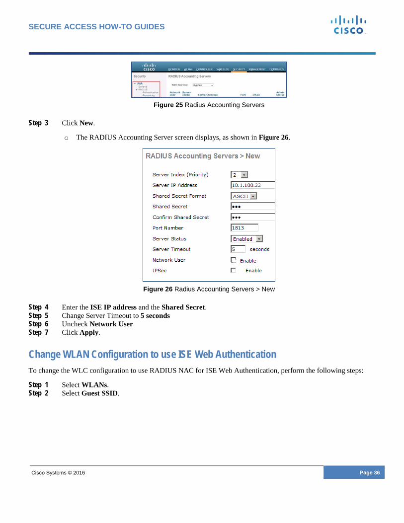
Figure 25 Radius Accounting Servers
Step 3 Click New.
o The RADIUS Accounting Server screen displays, as shown in Figure 26.
Figure 26 Radius Accounting Servers > New
Step 4 Enter the ISE IP address and the Shared Secret. Step 5 Change Server Timeout to 5 seconds Step 6 Uncheck Network User Step 7 Click Apply.
Change WLAN Configuration to use ISE Web Authentication To change the WLC configuration to use RADIUS NAC for ISE Web Authentication, perform the following steps:
Step 1 Select WLANs. Step 2 Select Guest SSID.

Cisco Systems © 2016 Page 37
SECURE ACCESS HOW-TO GUIDES
Figure 27 WLANs
Step 3 Click the Security tab. Step 4 Click the Layer 2 tab.
o Layer 2 Security tab options display, as shown in Figure 28.
Figure 28 Security > Layer 2
Step 5 For Layer 2 Security, select None. Step 6 Enable MAC Filtering. Step 7 Click the Layer 3 tab.
o Layer 3 Security tab options display, as shown in Figure 29.
Figure 29 Security > Layer 3
Step 8 Select None. Step 9 Select AAA Servers.
o The AAA Servers options displays, as shown in Figure 30.

Cisco Systems © 2016 Page 38
SECURE ACCESS HOW-TO GUIDES
Figure 30 Security > AAA Servers
Step 10 Select and enable your ISE server IP under Server 1 label for Authentication and Accounting, as shown in Figure 31.
Figure 31 Security > AAA Servers
Step 11 Click the Advanced Tab. Step 12 The Advanced Tab options display, as shown in Figure 32.
Figure 32 Advanced
Step 13 Enable Allow AAA Override. Step 14 Select None for Override Interface ACL. Step 15 Under NAC State select RADIUS NAC using the drop-down menu. Step 16 Enable Client User Idle Timeout and set to 1800 secs Step 17 Click Apply.

Cisco Systems © 2016 Page 39
SECURE ACCESS HOW-TO GUIDES

Cisco Systems © 2016 Page 40
SECURE ACCESS HOW-TO GUIDES
Configure ACLs for Guest Redirection and Permit Access This section describes how to configure an ACL on the WLC. The objective is to configure an ACL that allows guest clients to access guest services.
Configure an ACL to Redirect Guest Devices to ISE Guest Portal
Step 1 Go to the WLC GUI and choose Security > Access Control Lists > Access Control Lists.
o The Access Control Lists page appears, as shown in Figure 33. This page lists the ACLs that are configured on the WLC. It also enables you to edit or remove any of the ACLs.
Figure 33 Security > Access Control Lists
Step 2 Click the New to create a new ACL. Step 3 Enter guest-redirect as the name, as shown in Figure 34. Step 4 Click Edit in order to create rules for the ACL.
Figure 34 Access Control Lists
Step 5 Click Apply.
o You will be brought to the main listing, click the new ACL and you will see the following shown in Figure 35.
Figure 35 Access Control Lists > Edit

Cisco Systems © 2016 Page 41
SECURE ACCESS HOW-TO GUIDES
Step 6 Click Add New Rule. Step 7 The Access Control Lists > Rules page appears. Step 8 Configure the rules as shown in Figure 36.
Note: 10.1.100.22 is the IP address of ISE (use your ISE IP address)
Figure 36 ACL Entry for Guest Redirection
Configure an ACL to Permit Guest Access to the Internet After Authenticated Step 1 The WLC wizard created an ACL on setup called guest-acl. Click the guest-acl ACL. Step 2 Add the following two new rules after Sequence 2.
Note: IT IS VERY IMPORTANT THAT THESE STEPS ARE DONE IN ORDER.
• Permit any to access the source ISE IP • Permit any to access destination ISE IP
o Figure 37 shows the two new rules added after Sequence 2. o Note the ACL below is not the full ACL the WLAN Express created, just part of it to show where you need
to inject the extra ACEs
Figure 37 ACL Entry for Guest Permit
Note: 10.1.100.22 is the IP address of the ISE server. Use your ISE IP address for the new rules.
o This completes the first part of the Cisco Identity Services Engine with WLC for
Guest Services process - Installing and configuring Cisco Wireless Controller (WLC).

Cisco Systems © 2016 Page 42
SECURE ACCESS HOW-TO GUIDES
Configure ISE for Guest Access Now that you have configured the Wireless Controller to work with ISE Web Authentication, you must complete the necessary steps on ISE.
The flow diagram shown in Figure 38 shows the process for Configuring ISE for Guest Services.
Figure 38 Part 2 Flow - Configure ISE for Guest Services
Configure WLC for ISE Web Authentication
Configure Required Settingsfor Sponsored Guest Flows
(Optional)
Set Up a Well-known Certificate(Optional)
Configure Basic Portal Customization
(Optional)Configure ISE for Guest Services
What’s Next
Configure WLC as aNetwork Access Device
Create an AuthenticationPolicy
Part 2 – Configuring WLC and ISE for Guest Services
Set Changes for Admin and Guest Accounts
(Optional)
Configure Minimum Settingsfor Self-Registration
(Optional)
Create an AuthorizationProfile
Create an AuthorizationPolicy

Cisco Systems © 2016 Page 43
SECURE ACCESS HOW-TO GUIDES
Configure the Wireless Controller (WLC) as a Network Access Device (NAD) Step 1 Login to ISE Admin UI. Step 2 Navigate to Administration > Network Resources > Network Devices. Step 3 Select Add, as shown in Figure 39.
Figure 39 Add Network Device
o The Network Devices edit page displays, as shown in Figure 40.
Figure 40 New Network Device Addition
Step 4 Enter a device name. Step 5 Enter the device IP Address. Step 6 Enable Authentication Settings. Step 7 Enter the Shared Secret (Pre-checklist item number - 12). Step 8 Click Submit.

Cisco Systems © 2016 Page 44
SECURE ACCESS HOW-TO GUIDES
Authentication Policy Setup An authentication policy allows you to statically define the allowed protocols and the identity source or identity source sequence that Cisco ISE will use for communication. Cisco ISE provides a preconfigured working authentication policy for guest access by default.
Viewing Default Authentication Policy To view the preconfigured default authentication policy, perform the following steps:
Step 1 Login to ISE Admin UI. Step 2 Navigate to Policy > Authentication.
o The Default Authentication Policy page appears, as shown in Figure 41.
Figure 41 Default Authentication Policy
In the default authentication policy, MAB for unknown internal endpoints is set to Continue, which allows guest endpoints (which are unknown) to continue authentication and be authorized for redirection to the guest portal.
Create an Authorization Profile to Redirect Guest Endpoints to ISE When endpoints first access the network, they are authenticated with MAB, and must be redirected to the guest portal for authorization. ISE 2.0 comes with a built-in profile called Cisco_WebAuth. You will modify this to work with your guest installation.
Step 1 Navigate to Policy > Policy Elements > Results. Step 2 Expand Authorization and click Authorization Profiles. Step 3 Select Cisco_WebAuth Step 4 Change the profile to work for your setup:
o Under Web Redirection choose the type of Redirection: Hotspot or Centralized Web Authentication (used for Self-Registration or Sponsored Guest Flows).
o ACL: The ACL is case-sensitive and must match the name configured in the WLC. Use guest-redirect as configured in the Configure ACLs for Guest redirection and Permit Access section.
Note: The ACL is case-sensitive and must match the definition in WLC exactly.
o Value: Choose the appropriate default portal (Hotspot, Self-Registration, or Sponsored).
Cisco Systems © 2016 Page 45
SECURE ACCESS HOW-TO GUIDES
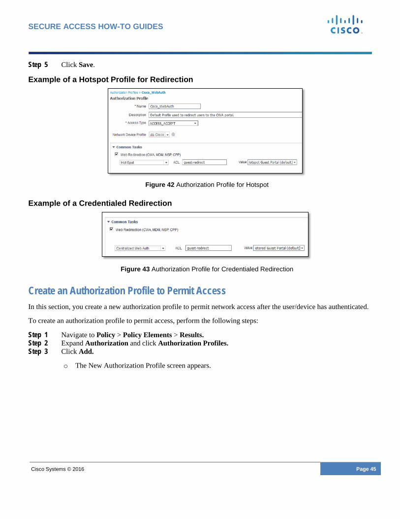
Step 5 Click Save.
Example of a Hotspot Profile for Redirection
Figure 42 Authorization Profile for Hotspot
Example of a Credentialed Redirection
Figure 43 Authorization Profile for Credentialed Redirection
Create an Authorization Profile to Permit Access In this section, you create a new authorization profile to permit network access after the user/device has authenticated.
To create an authorization profile to permit access, perform the following steps:
Step 1 Navigate to Policy > Policy Elements > Results. Step 2 Expand Authorization and click Authorization Profiles. Step 3 Click Add.
o The New Authorization Profile screen appears.
Cisco Systems © 2016 Page 46
SECURE ACCESS HOW-TO GUIDES
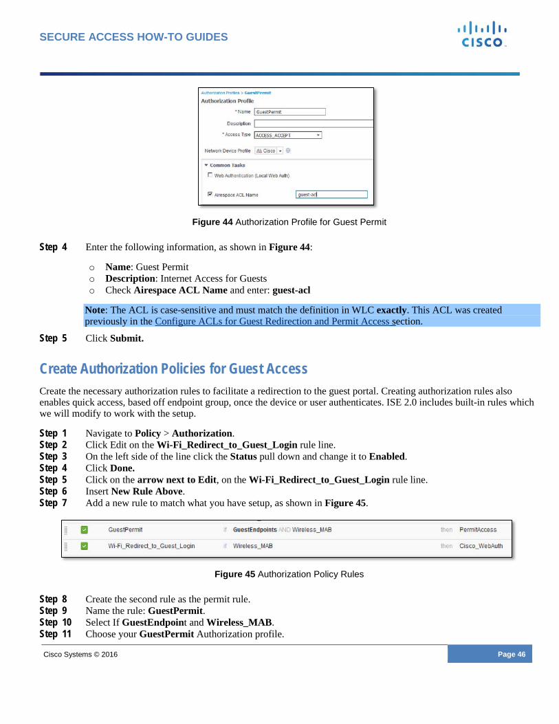
Figure 44 Authorization Profile for Guest Permit
Step 4 Enter the following information, as shown in Figure 44:
o Name: Guest Permit o Description: Internet Access for Guests o Check Airespace ACL Name and enter: guest-acl
Note: The ACL is case-sensitive and must match the definition in WLC exactly. This ACL was created previously in the Configure ACLs for Guest Redirection and Permit Access section.
Step 5 Click Submit.
Create Authorization Policies for Guest Access Create the necessary authorization rules to facilitate a redirection to the guest portal. Creating authorization rules also enables quick access, based off endpoint group, once the device or user authenticates. ISE 2.0 includes built-in rules which we will modify to work with the setup.
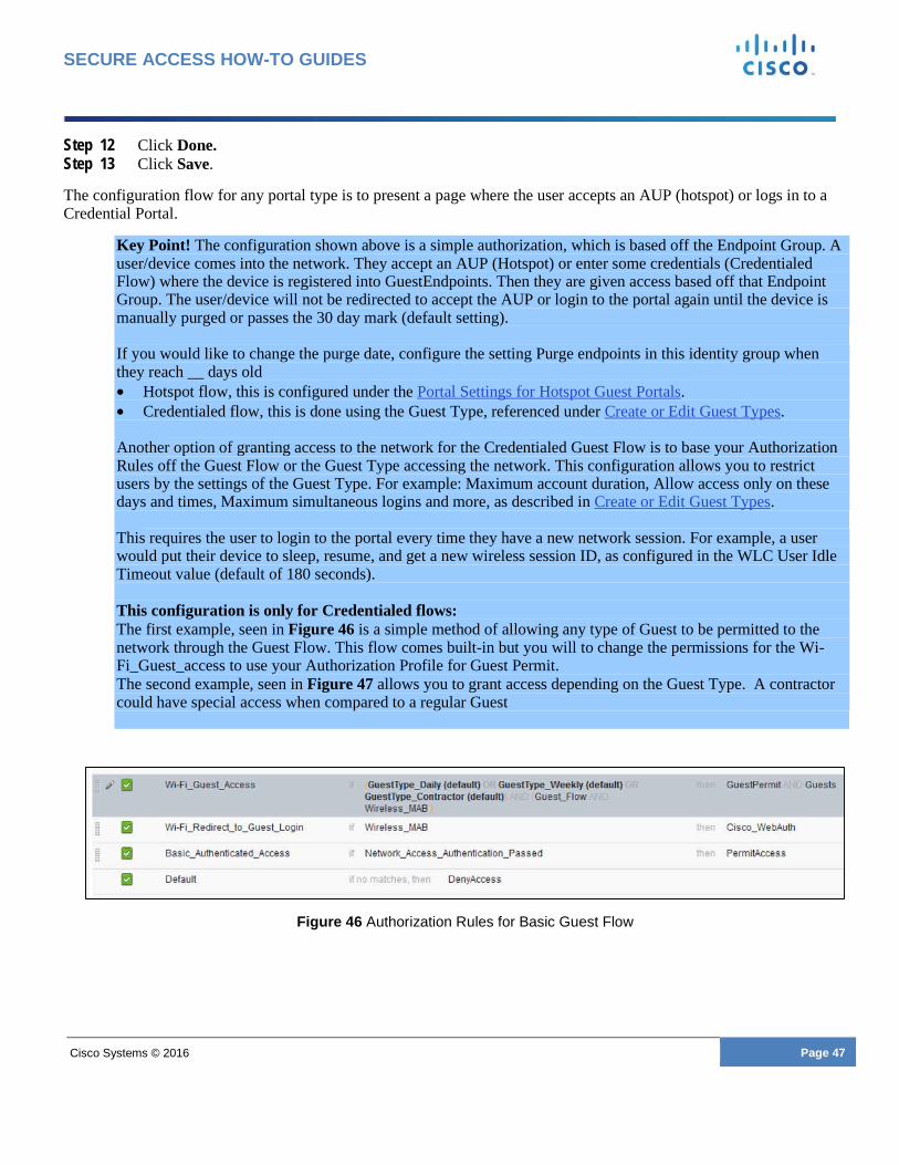
Step 1 Navigate to Policy > Authorization. Step 2 Click Edit on the Wi-Fi_Redirect_to_Guest_Login rule line. Step 3 On the left side of the line click the Status pull down and change it to Enabled. Step 4 Click Done. Step 5 Click on the arrow next to Edit, on the Wi-Fi_Redirect_to_Guest_Login rule line. Step 6 Insert New Rule Above. Step 7 Add a new rule to match what you have setup, as shown in Figure 45.
Figure 45 Authorization Policy Rules
Step 8 Create the second rule as the permit rule. Step 9 Name the rule: GuestPermit. Step 10 Select If GuestEndpoint and Wireless_MAB. Step 11 Choose your GuestPermit Authorization profile.
Cisco Systems © 2016 Page 47
SECURE ACCESS HOW-TO GUIDES
Step 12 Click Done. Step 13 Click Save.
The configuration flow for any portal type is to present a page where the user accepts an AUP (hotspot) or logs in to a Credential Portal.
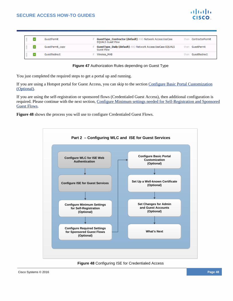
Key Point! The configuration shown above is a simple authorization, which is based off the Endpoint Group. A user/device comes into the network. They accept an AUP (Hotspot) or enter some credentials (Credentialed Flow) where the device is registered into GuestEndpoints. Then they are given access based off that Endpoint Group. The user/device will not be redirected to accept the AUP or login to the portal again until the device is manually purged or passes the 30 day mark (default setting). If you would like to change the purge date, configure the setting Purge endpoints in this identity group when they reach __ days old • Hotspot flow, this is configured under the Portal Settings for Hotspot Guest Portals. • Credentialed flow, this is done using the Guest Type, referenced under Create or Edit Guest Types. Another option of granting access to the network for the Credentialed Guest Flow is to base your Authorization Rules off the Guest Flow or the Guest Type accessing the network. This configuration allows you to restrict users by the settings of the Guest Type. For example: Maximum account duration, Allow access only on these days and times, Maximum simultaneous logins and more, as described in Create or Edit Guest Types. This requires the user to login to the portal every time they have a new network session. For example, a user would put their device to sleep, resume, and get a new wireless session ID, as configured in the WLC User Idle Timeout value (default of 180 seconds). This configuration is only for Credentialed flows: The first example, seen in Figure 46 is a simple method of allowing any type of Guest to be permitted to the network through the Guest Flow. This flow comes built-in but you will to change the permissions for the Wi-Fi_Guest_access to use your Authorization Profile for Guest Permit. The second example, seen in Figure 47 allows you to grant access depending on the Guest Type. A contractor could have special access when compared to a regular Guest
Figure 46 Authorization Rules for Basic Guest Flow
Cisco Systems © 2016 Page 48
SECURE ACCESS HOW-TO GUIDES
Figure 47 Authorization Rules depending on Guest Type
You just completed the required steps to get a portal up and running.
If you are using a Hotspot portal for Guest Access, you can skip to the section Configure Basic Portal Customization (Optional).
If you are using the self-registration or sponsored flows (Credentialed Guest Access), then additional configuration is required. Please continue with the next section, Configure Minimum settings needed for Self-Registration and Sponsored Guest Flows.
Figure 48 shows the process you will use to configure Credentialed Guest Flows.
Figure 48 Configuring ISE for Credentialed Access
Configure WLC for ISE Web Authentication
Configure Required Settingsfor Sponsored Guest Flows
(Optional)
Set Up a Well-known Certificate(Optional)
Configure Basic Portal Customization
(Optional)
Configure ISE for Guest Services
What’s Next
Part 2 – Configuring WLC and ISE for Guest Services
Set Changes for Admin and Guest Accounts
(Optional)
Configure Minimum Settingsfor Self-Registration
(Optional)

Cisco Systems © 2016 Page 49
SECURE ACCESS HOW-TO GUIDES
Cisco Systems © 2016 Page 50
SECURE ACCESS HOW-TO GUIDES
Configure Minimum Settings for Self-Registration and Sponsored Guest Flows
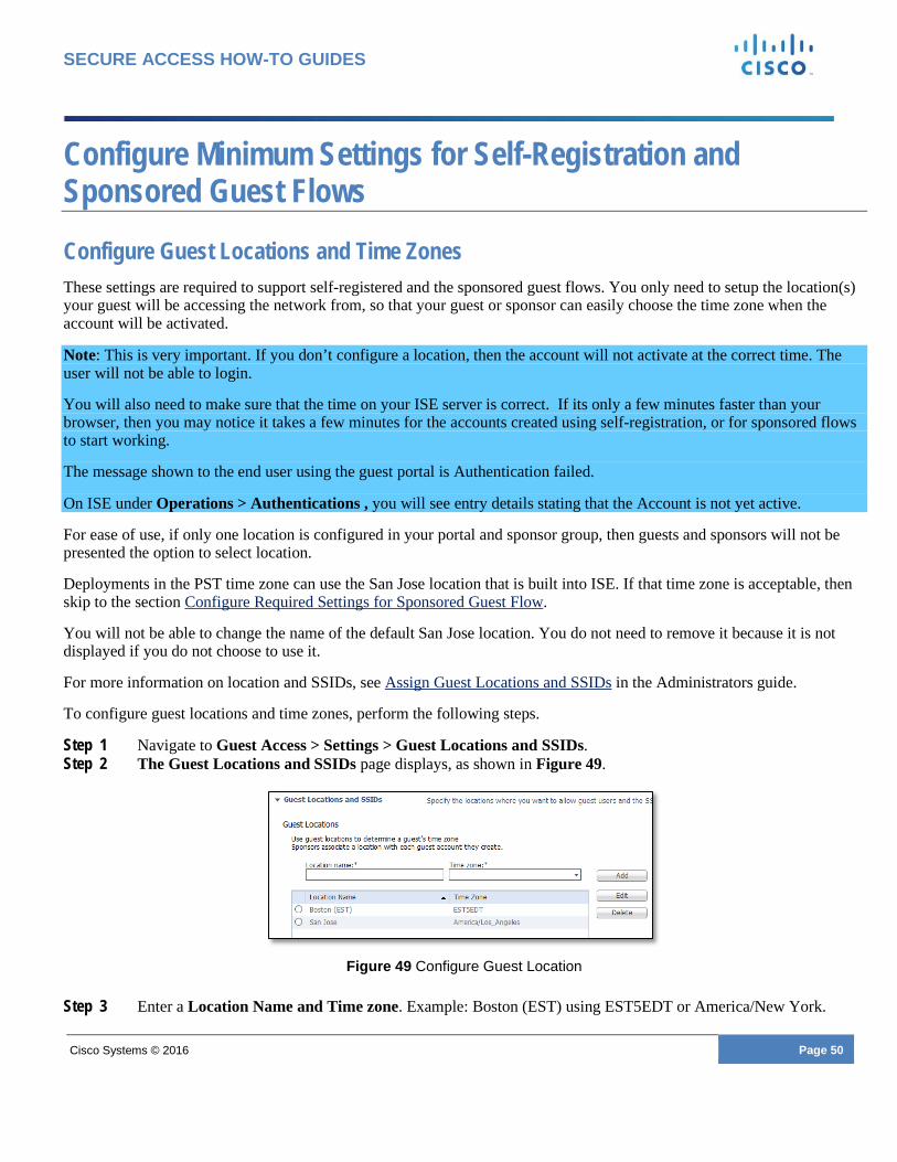
Configure Guest Locations and Time Zones These settings are required to support self-registered and the sponsored guest flows. You only need to setup the location(s) your guest will be accessing the network from, so that your guest or sponsor can easily choose the time zone when the account will be activated.
Note: This is very important. If you don’t configure a location, then the account will not activate at the correct time. The user will not be able to login.
You will also need to make sure that the time on your ISE server is correct. If its only a few minutes faster than your browser, then you may notice it takes a few minutes for the accounts created using self-registration, or for sponsored flows to start working.
The message shown to the end user using the guest portal is Authentication failed.
On ISE under Operations > Authentications , you will see entry details stating that the Account is not yet active.
For ease of use, if only one location is configured in your portal and sponsor group, then guests and sponsors will not be presented the option to select location.
Deployments in the PST time zone can use the San Jose location that is built into ISE. If that time zone is acceptable, then skip to the section Configure Required Settings for Sponsored Guest Flow.
You will not be able to change the name of the default San Jose location. You do not need to remove it because it is not displayed if you do not choose to use it.
For more information on location and SSIDs, see Assign Guest Locations and SSIDs in the Administrators guide.
To configure guest locations and time zones, perform the following steps.
Step 1 Navigate to Guest Access > Settings > Guest Locations and SSIDs. Step 2 The Guest Locations and SSIDs page displays, as shown in Figure 49.
Figure 49 Configure Guest Location
Step 3 Enter a Location Name and Time zone. Example: Boston (EST) using EST5EDT or America/New York.

Cisco Systems © 2016 Page 51
SECURE ACCESS HOW-TO GUIDES
Note: Do not delete the San Jose Location.
Step 4 Click Add. Step 5 Click Save.
Configure the Portal to Use the Location (Self-Registration) You must configure the self-registration portal to use this newly added location. If you are not using Self-Registration, then please skip to the section below, Configure Required Settings for Sponsored Guest Flow. Otherwise, continue to the section, Setting Up a Well-known Certificate (Optional).
Note: If San Jose (PST time) as a default is acceptable, then you may skip this section.
Step 1 Navigate to Guest Access > Configure > Guest Portals. Step 2 Choose the Self-registered Guest portal. Step 3 Collapse Portal Settings and Login page settings. Step 4 Under Self-Registration Page Settings, Location: Add in the location you created, as shown in Figure 50. Step 5 Click Add. Step 6 Click Submit.
Figure 50 Guest Portal Choose Location

Cisco Systems © 2016 Page 52
SECURE ACCESS HOW-TO GUIDES
Configure Required Settings for Sponsored Guest Flow The following steps are required to support Sponsored Guests. If you are only using Self-Registration, then setup is complete, and you can skip this process and move to the section Setting Up a Well-known Certificate (Optional).
Working with Sponsor Accounts Setup your sponsors by either creating an internal account or configuring ISE to integrate with Active Directory. If you are integrating with Active Directory, skip to the section Using Sponsor Accounts from Active Directory.
To create an internal account, perform the following steps.
Step 1 Navigate to Administration > Identity Management > Identities > Users. Step 2 Click Add. Step 3 Fill in the information for the Sponsor. Step 4 Select ALL_ACCOUNTS (default), under User Groups. Step 5 Click Submit. Step 6 Skip to the section Configure Locations For Your Sponsor Group.
Using Sponsor Accounts from Active Directory The following two sections are only needed if you are integrating your Guest Access system with an Active Directory server that contains your sponsor groups. If you are planning to use Sponsor accounts created on ISE (completed in the previous section), and do not wish to combine them with AD, then you can skip below to Configure Locations For Your Sponsor Group.
For more information, refer to Active Directory as an External Identity Source in the ISE Configuration Guide.
To create sponsor accounts from Active Directory, perform the following steps.
Step 1 Navigate to Administration > Identity Management > External Identity Sources. Step 2 Select Active Directory. Step 3 Click Add, as shown in Figure 51.
Figure 51 Add Active Directory Join Point
Step 4 As shown in Figure 52, enter the Join Point Name and Active Directory Domain.

Cisco Systems © 2016 Page 53
SECURE ACCESS HOW-TO GUIDES
Step 5 Click Submit.
Figure 52 Configure Join Point Connection
Step 6 You are prompted with: “Would you like to Join all ISE Nodes to the Active Directory Domain”, click Yes. Step 7 You are asked to enter your credentials for joining the domain. This includes specifying the Organizational Unit
(optional). See the info buttons for more details on what is required.
Note: The domain credentials are not saved by ISE. This is a one time use to setup the initial connection for the machine account.
Figure 53 Join AD Domain
Step 8 You will see a Successful message as shown in Figure 54. Click Close.

Cisco Systems © 2016 Page 54
SECURE ACCESS HOW-TO GUIDES
Figure 54 Join Operation Status
Step 9 Click the Groups tab. Step 10 Click Add, select Groups from Directory as seen in Figure 55.
Figure 55 Select Groups from AD
Step 11 Click Retrieve Groups, as shown in Figure 56. Step 12 After you choose the groups that contain the users who will be sponsoring guests, click OK at the bottom of the
page.
Figure 56 Select Directory Groups
Step 13 After you choose your groups your screen will look like Figure 57 . Click Save at the bottom of this Groups
page.
Figure 57 Groups

Cisco Systems © 2016 Page 55
SECURE ACCESS HOW-TO GUIDES
You have now completed setup of Active Directory Groups that can be used to assign to your sponsor groups.
Set up the Active Directory Sponsor Group in All_Accounts The following steps show how to associate the group containing your sponsors or employees to the sponsor group. In this example, we use Domain Users.
Step 1 Navigate to Guest Access > Configure > Sponsor Groups > ALL_ACCOUNTS.
o The Sponsor Group page displays, as shown in Figure 58.
Figure 58 Select Sponsor Group Members
Step 2 Click the Member and move Domain Users over to the Selected User Groups area, as shown in Figure 36.
Figure 59 Select Sponsor Group Members
Step 3 Click OK.
Configure Locations for Your Sponsor Group It is important to configure the correct locations to use when sponsors create your guest accounts. If you’re ok using the San Jose location, you may skip over this section. Otherwise add your new location.
Step 1 Select the locations you want your sponsors to use from the Select the locations that guests will be visiting section, as shown in Figure 60.
Step 2 Remove the locations you do not need.

Cisco Systems © 2016 Page 56
SECURE ACCESS HOW-TO GUIDES
Figure 60 Select Locations for Guest Type
Step 3 Scroll to the top of the page and click Save. Step 4 Click Close.
Setup ISE Sponsor Portal FQDN Based Access A sponsor portal allows a sponsor to create temporary accounts for guests, visitors, contractors, consultants, or customers to perform HTTP or HTTPS login to gain access to the network. The network could be a corporate network or access could provide access to the Internet.
There are two ways to access the Sponsor Portal via the ISE admin UI without any special configuration.
• Manage Accounts Button - This is reserved for Administrators • Portal Test URL - This URL can be sent to your sponsors so they can easily bookmark the site – This is the
default
The recommendation is to provide your sponsors with an easy Sponsor Portal URL. Here is an example: http://sponsorportal.yourcompany.com
Follow the steps below to see how to provide access to a complex URL or an easy one.
Step 1 Navigate to Guest Access > Configure > Sponsor Portals. Step 2 Click on Sponsor portal (default), the Portal Settings pane appears as shown in Figure 61.
Figure 61 Sponsor Settings
Step 3 Click on the Portal test URL and a new browser window will open.
Note: This is an example URL you would need to send to your sponsors if you don’t proceed with the steps below for FQDN portal name. “https://ise.securitydemo.net:8443/sponsorportal/PortalSetup.action?portal=28981f50-e96e-11e4-a30a-005056bf01c9”

Cisco Systems © 2016 Page 57
SECURE ACCESS HOW-TO GUIDES
Step 4 Close the Portal Test URL window. Step 5 Under Portal Settings locate the Fully Qualified Domain Name (FQDN) section as shown in Figure 62, then
enter “sponsorportal.yourcompany.com”
Figure 62 Portal Settings > FQDN
Step 6 Scroll to the top and click Save.
You now need to update your DNS to ensure this FQDN resolves to your ISE IP address. This may be accomplished by using a CNAME Alias pointing sponsorportal.yourcompany.com to yourise.

Cisco Systems © 2016 Page 58
SECURE ACCESS HOW-TO GUIDES
Configure Basic Portal Customization (Optional) The following section is not required to get your system up and running for Guest access. It is an optional step to help familiarize basic customization options for your new Guest portal. If you’re not interested in customizing your portal please continue to the section Setting Up a Well-known Certificate (Optional).
For more information on Guest Customization please reference the Customize End-User Web Portals section of the Administrator’s guide and the HowTo: ISE Web Portal Customization Options at our Design guide site
To customize a guest portal, perform the following steps.
Step 1 Click Guest Access > Configure > Guest Portals. Step 2 Click on the portal you are using (Hotspot, Self-Registered or Sponsored) to edit that portal.
o The portal that is active is shown with a Green encircled check, as shown in Figure 63.
Figure 63 Active Hotspot Portal
Step 3 Click on the Page Customization section at the top of the page, as shown Figure 64.
Figure 64 Portal Page Customization
o ISE gives you basic customization built right into the product. It also makes it easier to see what changes you are making in real-time. We won’t go into detail of all of these, but notice at the top of the page you can change things like the logos, banner and main text elements. You can also choose from some built in color themes.
Step 4 To change the theme colors of your portal, use a built-in Portal theme or use the Tweaks to modify your colors, as shown in Figure 65.

Cisco Systems © 2016 Page 59
SECURE ACCESS HOW-TO GUIDES
Figure 65 Page Customization Options
Step 5 You can upload a logo and a banner to use with your portal.
Below this main section in the UI is where you can tweak the overall look and feel. You can also go into each of the pages. Depending on your portal settings and portal type, you see different options on the left hand side of the page. You can tweak the text in the different areas on the page.
There is also a mini-preview that shows your changes to the portal.
Figure 66 Portal Customization Mini Editor and preview
Step 6 After doing some basic customization, check out the desktop preview (same as the portal test URL at the top of the page) by clicking on the option in the bottom right of the mini preview.
Note: You can also test the full flow a user would go through without using a real client by using the Portal test URL at the top of the page.
Step 7 Close the desktop preview browser window. Step 8 Click Save at the top of the page. As shown in Figure 67.
Figure 67 Save customization

Cisco Systems © 2016 Page 60
SECURE ACCESS HOW-TO GUIDES
You have now completed basic customization of your guest portal. You can also do the same with your Sponsor Portal, if you’re using Sponsored Guest Access. To do this, navigate to Guest Access > Configure > Sponsor Portals > Select the default portal, and follow the same steps you used to customize your Guest Portal.
You can continue with the next section Setting Up a Well-known Certificate (Optional) or Skip to What’s Next.

Cisco Systems © 2016 Page 61
SECURE ACCESS HOW-TO GUIDES
Setting up a Well-known Certificate (Optional) The following section is not required to get your system up and running for guest access, but it is highly recommended. To ensure that your users will not have to accept an invalid certificate when connecting to the Guest, Sponsor or Administrator Portal(s) via their web browser, use a certificate that has been signed by a well-known Certificate Authority for your ISE server.
If you would like to skip this section for now, you may continue to the section, What’s Next. You are done with the minimum setup.
SSL.com is one known vendor that has full support for the certificate type being recommended in this guide, but there are other providers that will work.
Note: Each certificate provider may refer to the certificate type with a different name. It often helps to call the company or use their online web-chat to explain what is needed w/ the SAN field(s). Tell them you are looking for a certificate that contains a wildcard and FQDN both in the SAN field, with an FQDN in the CN= field. For more information on wildcard certificates and certificate in general please reference the following documents:
• ISE Administrator Guide - Wildcard Certificate Support in Cisco ISE • Moving Packets Article - When SSL Certificates Go Wild • Aaron Woland Network World Blog - Wildcard certificates and how to use with ISE • Aaron Woland How To Guide - HowTo: Implement Cisco ISE and Server Side Certificates
The steps listed in the next process show an example of setting up a Unified Communications Certificate (UCC) with wildcard in the SAN from SSL.com, which is a subordinate of Comodo.
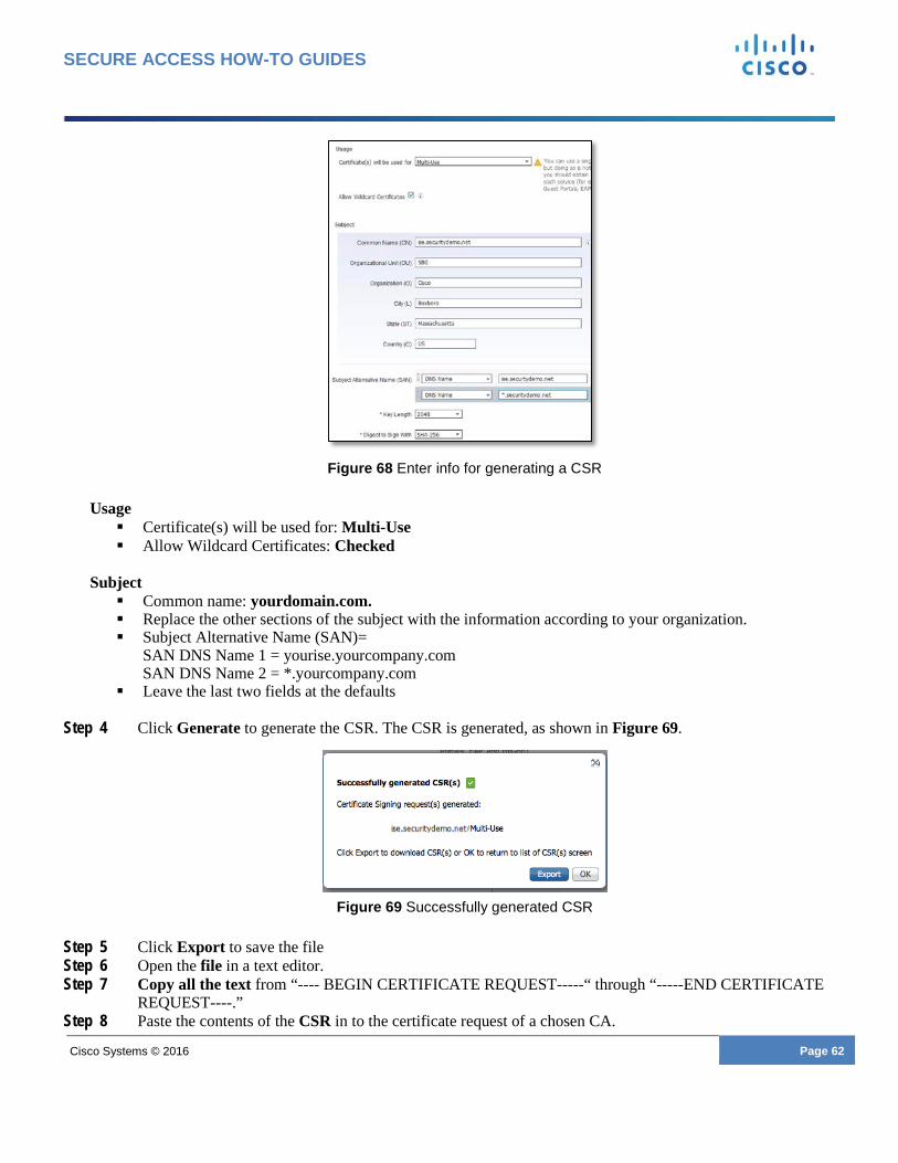
Create a Certificate Signing Request and Submit the CSR to a Certificate Authority Step 1 Navigate to Administration > System > Certificates > Certificate Signing Requests. Step 2 Click Generate Certificate Signing Requests (CSR). Step 3 Enter the values for generating a CSR, as shown in Figure 68.
Cisco Systems © 2016 Page 62
SECURE ACCESS HOW-TO GUIDES
Figure 68 Enter info for generating a CSR
Usage Certificate(s) will be used for: Multi-Use Allow Wildcard Certificates: Checked
Subject Common name: yourdomain.com. Replace the other sections of the subject with the information according to your organization. Subject Alternative Name (SAN)=
SAN DNS Name 1 = yourise.yourcompany.com SAN DNS Name 2 = *.yourcompany.com
Leave the last two fields at the defaults
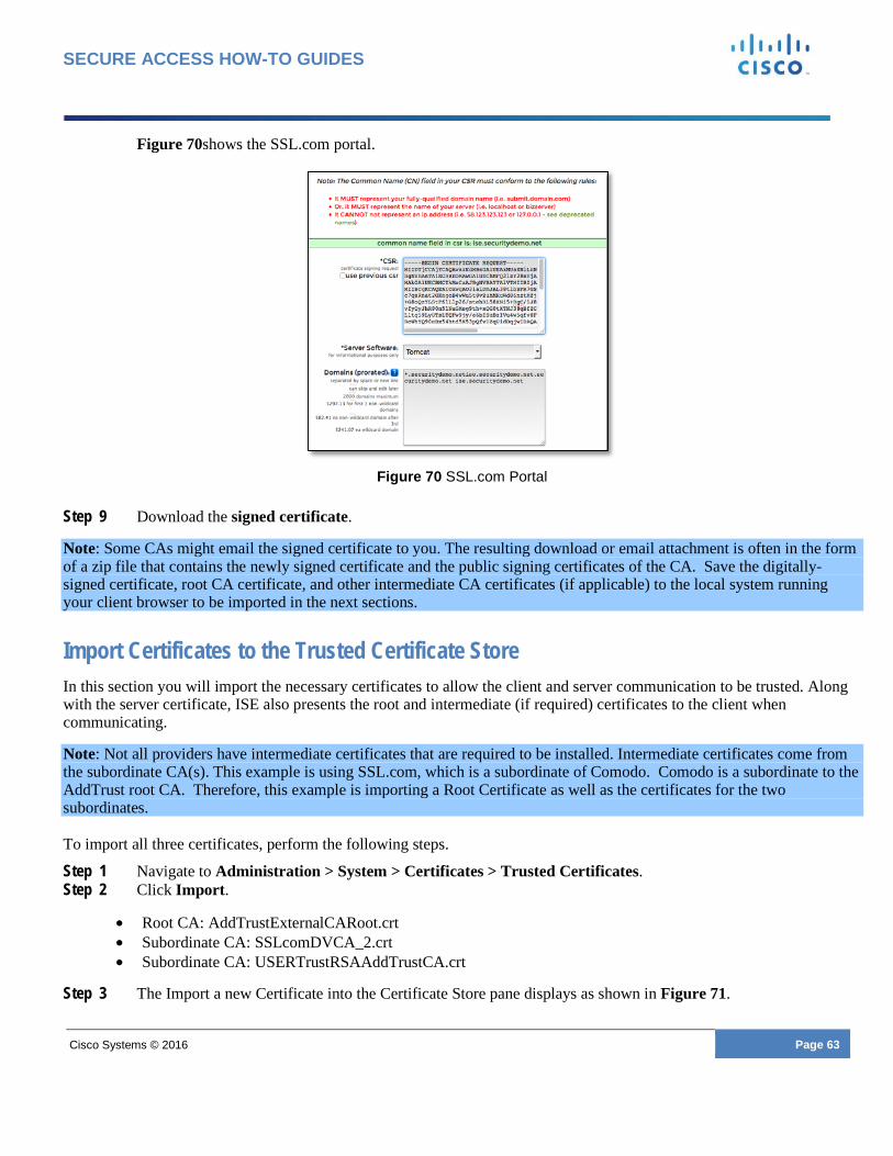
Step 4 Click Generate to generate the CSR. The CSR is generated, as shown in Figure 69.
Figure 69 Successfully generated CSR
Step 5 Click Export to save the file Step 6 Open the file in a text editor. Step 7 Copy all the text from “---- BEGIN CERTIFICATE REQUEST-----“ through “-----END CERTIFICATE
REQUEST----.” Step 8 Paste the contents of the CSR in to the certificate request of a chosen CA.
Cisco Systems © 2016 Page 63
SECURE ACCESS HOW-TO GUIDES
Figure 70shows the SSL.com portal.
Figure 70 SSL.com Portal
Step 9 Download the signed certificate.
Note: Some CAs might email the signed certificate to you. The resulting download or email attachment is often in the form of a zip file that contains the newly signed certificate and the public signing certificates of the CA. Save the digitally-signed certificate, root CA certificate, and other intermediate CA certificates (if applicable) to the local system running your client browser to be imported in the next sections.
Import Certificates to the Trusted Certificate Store In this section you will import the necessary certificates to allow the client and server communication to be trusted. Along with the server certificate, ISE also presents the root and intermediate (if required) certificates to the client when communicating.
Note: Not all providers have intermediate certificates that are required to be installed. Intermediate certificates come from the subordinate CA(s). This example is using SSL.com, which is a subordinate of Comodo. Comodo is a subordinate to the AddTrust root CA. Therefore, this example is importing a Root Certificate as well as the certificates for the two subordinates. To import all three certificates, perform the following steps.
Step 1 Navigate to Administration > System > Certificates > Trusted Certificates. Step 2 Click Import.
• Root CA: AddTrustExternalCARoot.crt • Subordinate CA: SSLcomDVCA_2.crt • Subordinate CA: USERTrustRSAAddTrustCA.crt
Step 3 The Import a new Certificate into the Certificate Store pane displays as shown in Figure 71.

Cisco Systems © 2016 Page 64
SECURE ACCESS HOW-TO GUIDES
Figure 71 Import a new Certificate into the store
Step 4 Use these steps to import the following certificates:
• Root CA: AddTrustExternalCARoot.crt • Subordinate CA: SSLcomDVCA_2.crt • Subordinate CA: USERTrustRSAAddTrustCA.crt
Step 5 Click Browse to select the root CA certificate. Step 6 Enter a Friendly Name. Step 7 Choose the root certificate returned by your CA. Step 8 Under Trusted For: Check the boxes for Trust for Authentication within ISE and Trust for client
authentication and Syslog. Step 9 It is also recommended that you select Validate Certificate Extensions Step 10 Enter a description. Step 11 Click Submit.
Bind the CA-Signed Certificate to the Signing Request Now that you have received the digitally signed certificate returned by your CA, and imported the CA certificates, the next step is to bind the certificate signed by the CA to the CSR from ISE. This pairs the certificate and private key that was used to generate the CSR.
Step 1 Navigate to Administration > System > Certificates > Certificate Signing Requests. Step 2 Select the entry for your signing request. Step 3 Click Bind Certificate, as shown in Figure 72.
Figure 72 Select Certificate to Bind
Step 4 Click Browse to choose the CA-signed certificate. Step 5 Specify a Friendly Name for the certificate. Step 6 Under Usage check the following options: Admin, EAP Authentication, Portal Step 7 For Portal Group Tag select Default Portal Certificate Group

Cisco Systems © 2016 Page 65
SECURE ACCESS HOW-TO GUIDES
Step 8 Click Submit to bind the CA-signed certificate, as shown in Figure 73. After you click submit the system restart and will be inaccessible for ~5 min
Figure 73 Bind Signed Certificate
You are done setting up ISE with a well-known certificate for ISE 2.0
For more information on working with certificates, please reference the Managing Certificates section of the Cisco ISE 2.0 Administration Guide.
Cisco Systems © 2016 Page 66
SECURE ACCESS HOW-TO GUIDES
Setting Changes for Admin & Guest Accounts (Optional) After your system is up and running, we recommended that you change the default settings for the following accounts:
o Familiarize yourself with the Administrator account password policy to prevent lockouts.
o Set the Guest default username and password requirements to make it easier for your users to manage and login.
Get Acquainted with the Administrator Password Policy A common issue seen when setting up ISE is that people forget to change their administrator account settings and they end up being locked out of the system if they haven’t used it for a while. It’s best to familiarize yourself with the requirements so that you understand them, and don’t get locked out if you don’t access the system for a while.
Navigate to Administration > System > Admin Access > Password Policy Change the settings as necessary. For example, Password Lifetime uncheck or extend the line for expiration.
Change Guest Account Requirements Out of the box, the ISE Guest solution has some fairly difficult password settings. These passwords are long and complex making them difficult to remember or even write down. For a better user experience you can change these settings. Also some devices make it difficult to tell them difference between the letter ‘O, l’ and the number ‘0, 1’, which leads to users having failed authentications. You could also reduce the number of characters to make it easier but mix it up a little to keep it a little complex.
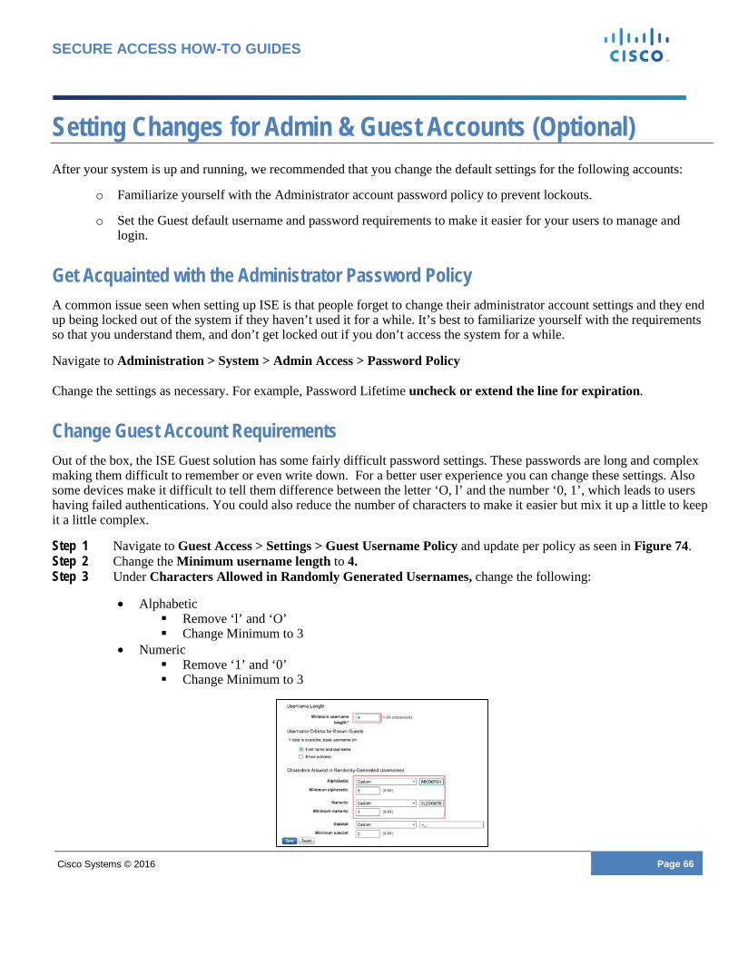
Step 1 Navigate to Guest Access > Settings > Guest Username Policy and update per policy as seen in Figure 74. Step 2 Change the Minimum username length to 4. Step 3 Under Characters Allowed in Randomly Generated Usernames, change the following:
• Alphabetic Remove ‘l’ and ‘O’ Change Minimum to 3
• Numeric Remove ‘1’ and ‘0’ Change Minimum to 3

Cisco Systems © 2016 Page 67
SECURE ACCESS HOW-TO GUIDES
Figure 74 Username Policy
Step 4 Click Save Step 5 Navigate to Guest Password Policy and change the following as seen in Figure 75:
• Password length: set to 4 • Minimum lowercase and uppercase: set to 0 • Minimum number: set to 4 • Minimum special: set to 0
Figure 75 Password Policy
Step 6 Click Save
Cisco Systems © 2016 Page 68
SECURE ACCESS HOW-TO GUIDES
What’s Next After configuring your ISE server, you should do the following to validate that it’s working:
For the Hot Spot Guest Flow
Step 1 Connect to the Guest SSID. Step 2 Login to the Hotspot Portal.
For the Self-Registered Guest Flow
Step 1 Connect to the Guest SSID. Step 2 Click on Don’t have an Account and create a guest account. Step 3 Login to the Self-Registered Portal
For the Sponsored Guest Flow
Step 1 Using a machine on the internal network, connect to the Sponsor Portal http://sponsorportal.yourdomain.com or use the Portal Test URL for Sponsor Portal Access. This is explained under the section, Setup ISE Sponsor Portal FQDN Based Access
Step 2 Login with a sponsor account. Step 3 Create a guest account. Step 4 Using another client, connect to the Guest SSID Step 5 Login with the newly created guest account.
For additional configuration options, please see Cisco ISE documentation at http://www.cisco.com/go/ise
For general recommended configuration of wireless controller, please reference: How-to:Universal WLC Config

Cisco Systems © 2016 Page 69
SECURE ACCESS HOW-TO GUIDES
Appendix A – Wireless Configuration Here are the commands that the ISE Wireless Guest Setup Wizard adds to the wireless system after it goes through the WLAN Express setup:
'config network web-auth captive-bypass enable' 'reset system' —REBOOT— 'config radius auth add 1 {ISE IP} 1812 ascii {RADIUS SECRET}', 'config radius auth disable 1', 'config radius auth retransmit-timeout 1 5', 'config radius auth rfc3576 enable 1', 'config radius auth network 1 enable', 'config radius auth management 1 disable', 'config radius auth enable 1', 'config radius acct add 1 {ISE IP} 1813 ascii {RADIUS SECRET}', 'config radius acct disable 1', 'config radius acct retransmit-timeout 1 5', 'config radius acct network 1 enable', 'config radius acct enable 1', 'config acl create guest-redirect', 'config acl rule add guest-redirect 1', 'config acl rule destination port range guest-redirect 1 0 65535', 'config acl rule action guest-redirect 1 permit', 'config acl rule source port range guest-redirect 1 53 53', 'config acl rule direction guest-redirect 1 out', 'config acl rule protocol guest-redirect 1 17', 'config acl rule add guest-redirect 2', 'config acl rule destination port range guest-redirect 2 53 53', 'config acl rule action guest-redirect 2 permit', 'config acl rule source port range guest-redirect 2 0 65535', 'config acl rule direction guest-redirect 2 in', 'config acl rule protocol guest-redirect 2 17', 'config acl rule add guest-redirect 3', 'config acl rule destination port range guest-redirect 3 0 65535', 'config acl rule destination address guest-redirect 3 {ISE IP} 255.255.255.255', 'config acl rule action guest-redirect 3 permit', 'config acl rule source port range guest-redirect 3 0 65535', 'config acl rule add guest-redirect 4', 'config acl rule destination port range guest-redirect 4 0 65535', 'config acl rule action guest-redirect 4 permit', 'config acl rule source port range guest-redirect 4 0 65535', 'config acl rule source address guest-redirect 4 {ISE IP} 255.255.255.255', 'config acl rule add guest-redirect 65', 'config acl rule destination port range guest-redirect 65 0 65535', 'config acl rule source port range guest-redirect 65 0 65535', 'config acl apply guest-redirect', 'config acl create guest-acl', 'config acl rule add guest-acl 1', 'config acl rule destination port range guest-acl 1 53 53', 'config acl rule action guest-acl 1 permit', 'config acl rule source port range guest-acl 1 0 65535', 'config acl rule protocol guest-acl 1 17',

Cisco Systems © 2016 Page 70
SECURE ACCESS HOW-TO GUIDES
'config acl rule add guest-acl 2', 'config acl rule destination port range guest-acl 2 0 65535', 'config acl rule action guest-acl 2 permit', 'config acl rule source port range guest-acl 2 53 53', 'config acl rule protocol guest-acl 2 17', 'config acl rule add guest-acl 3', 'config acl rule destination port range guest-acl 3 0 65535', 'config acl rule destination address guest-acl 3 {ISE IP} 255.255.255.255', 'config acl rule action guest-acl 3 permit', 'config acl rule source port range guest-acl 3 0 65535', 'config acl rule add guest-acl 4', 'config acl rule destination port range guest-acl 4 0 65535', 'config acl rule action guest-acl 4 permit', 'config acl rule source port range guest-acl 4 0 65535', 'config acl rule source address guest-acl 4 {ISE IP} 255.255.255.255', 'config acl rule add guest-acl 5', 'config acl rule destination port range guest-acl 5 0 65535', 'config acl rule destination address guest-acl 5 {GATEWAY IP} 255.255.255.255', 'config acl rule action guest-acl 5 permit', 'config acl rule source port range guest-acl 5 0 65535', 'config acl rule add guest-acl 65', 'config acl rule destination port range guest-acl 65 0 65535', 'config acl rule source port range guest-acl 65 0 65535', 'config acl apply guest-acl', 'config wlan disable {WLAN ID}', 'config wlan exclusionlist {WLAN ID} 60', 'config wlan flexconnect local-switching {WLAN ID} disable', 'config wlan security wpa akm 802.1x disable {WLAN ID}', 'config wlan security wpa wpa2 ciphers aes disable {WLAN ID}', 'config wlan security wpa wpa2 disable {WLAN ID}', 'config wlan security wpa disable {WLAN ID}', 'config wlan security web-auth server-precedence {WLAN ID} local radius ldap', 'config wlan security web-auth disable {WLAN ID}', 'config wlan security web-passthrough disable {WLAN ID}', 'config wlan aaa-override enable {WLAN ID}', 'config wlan mac-filtering enable {WLAN ID}', 'config wlan broadcast-ssid enable {WLAN ID}', 'config wlan session-timeout {WLAN ID} 1800', 'config wlan mfp client enable {WLAN ID}', 'config wlan radius_server auth add {WLAN ID} 1', 'config wlan radius_server acct add {WLAN ID} 1', 'config wlan wmm allow {WLAN ID}', 'config wlan nac radius enable {WLAN ID}', 'config wlan acl {WLAN ID} none', 'config wlan ipv6 acl {WLAN ID} none', 'config wlan radius_server acct interim-update 0 {WLAN ID}', 'config wlan radius_server acct interim-update enable {WLAN ID}', 'config wlan ccx AironetIeSupport disable {WLAN ID}', 'config wlan profiling radius all enable {WLAN ID}', 'config wlan enable {WLAN ID}',
'save config'
Guest-acl screenshot example:

Cisco Systems © 2016 Page 71
SECURE ACCESS HOW-TO GUIDES
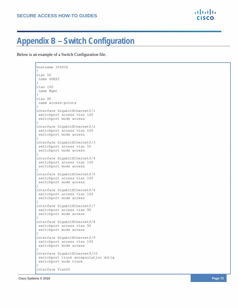
Cisco Systems © 2016 Page 72
SECURE ACCESS HOW-TO GUIDES
Appendix B – Switch Configuration Below is an example of a Switch Configuration file.
hostname 3560CG ! vlan 50 name GUEST ! vlan 100 name Mgmt ! vlan 90 name access-points ! interface GigabitEthernet0/1 switchport access vlan 100 switchport mode access ! interface GigabitEthernet0/2 switchport access vlan 100 switchport mode access ! interface GigabitEthernet0/3 switchport access vlan 50 switchport mode access ! interface GigabitEthernet0/4 switchport access vlan 100 switchport mode access ! interface GigabitEthernet0/5 switchport access vlan 100 switchport mode access ! interface GigabitEthernet0/6 switchport access vlan 100 switchport mode access ! interface GigabitEthernet0/7 switchport access vlan 90 switchport mode access ! interface GigabitEthernet0/8 switchport access vlan 90 switchport mode access ! interface GigabitEthernet0/9 switchport access vlan 100 switchport mode access ! interface GigabitEthernet0/10 switchport trunk encapsulation dot1q switchport mode trunk ! interface Vlan50
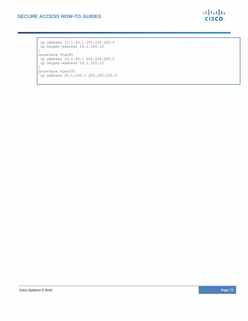
Cisco Systems © 2016 Page 73
SECURE ACCESS HOW-TO GUIDES
ip address 10.1.50.1 255.255.255.0 ip helper-address 10.1.100.10 ! interface Vlan90 ip address 10.1.90.1 255.255.255.0 ip helper-address 10.1.100.10 ! interface Vlan100 ip address 10.1.100.1 255.255.255.0


