Current Transformer (ANSI Std. C57.13) Function Function • Reduce current for measuring, control and protection purpose. The reduced current should be suitable for equipment connected on secondary side. Normally secondary current is 1, 2 and 5 A. • Separate primary and secondary circuit
Transcript
Current Transformer (ANSI Std. C57.13)
FunctionFunction
• Reduce current for measuring, control and protection purpose. The reduced current should be suitable for equipment connected on secondary side. Normally secondary current is 1, 2 and 5 A.
• Separate primary and secondary circuit
CT classification
1) Classification by CT class– Measurement CT e.g. W, KWh, A
• with specified operating range
– Protection CT with larger operating range
2) Classification by construction e.g. Wound Type, Bar Type, Window Type and Bushing Type
Bottom Core or Tank Type CT (36-300KV, 50-2000A)
1) Oil level Indicator4) Primary Terminal5) Core with secondary winding6) Core and coil assembly with main
with main insulation7) Insulator8) Base plate9) Terminal Box
1
23
4
5
6
7
8
9
Symbol, Polarity and Ratio
• Symbol and Polarity
H1 H2
X1 X2
Ipri
Isec
• Ratio1) Single Ratio e.g. 100:5A , 600:5A , 1200:5A 2) Multi Ratio e.g. 50/-/600:5 , 100/-/1200:5A ,
300/-/2000:5A
CT Ratings• Rated Dynamic Current
Maximum current with which CT can withstand without any damage.
• Accuracy Limit Factor (ALF)Ratio of IPRIMARY / IRATED at which CT accuracy is still within specific range.
Example 200/1A CT has ALF = 5It can maintain its accuracy in operation until IPRIMARY = 5 x 200 = 1,000 A.
• Rated BurdenValue of load on secondary side of CT based on its accuracy. Generally, it is defined in VA e.g. 2.5, 5, 7.5, 10, 15, 30 VA.
• Continuous Rated CurrentPrimary current which flows continuously through CT.
• Thermal - Short - Time Rated CurrentSymmetrical current on the primary side of CT, at which CT can withstand within specific time e.g. 0.5, 1, 2 or 3s and temperature does not exceed the winding withstand limit while short circuit on secondary side.
• Continuous - Thermal - Current Rating Factor (RF)Ratio of current during the temperature rise 30oC from ambient to continuous current e.g. 1.0, 1.33. 1.5, 2.0, 3.0, 4.0For example CT 100:5A , having RF = 1.5, can withstand the current 150:7.5A, while the temperature increases less than 30oC from ambient.
• Mechanical - Short - Time Current Rating (for Wound Type)Maximum current on primary side, when short circuit on secondary side occurs.
• Rated Secondary CurrentRated current on secondary side of CT, normally are 1, 2 or 5 A
• Nominal System Voltage (Max = 1.1 Nominal Voltage)• Basic Impulse Insulation Level (BIL)
Application and classes of CT
Metering CT
• Table 1 Limits of error for accuracy classes 0.1 to 1.0
Table 2 Limits of error for accuracy classes 3 and 5
Table 3 Limits of error for accuracy classes 5P and 10P
• Therefore, the definition of measuring core CT will be defined in Class and Burden
e.g. 0.3 B-0.1 or 0.6 B-0.5
Protection Cores
• Classes/error limits“C” or “T” with max. composite error equal or less
than 10% in the range of 1-20 times rated primary.• Hence, it can be compared with class 10 P 20 according to
IEC.
• For the definition of designation, it will be defined by its class and terminal voltage on secondary side, while CT has to generate the voltage for burden at 20 time rated secondary current and Ratio Error < 10% e.g. C100, C400.
Standard Burdens: (for 5A secondary current)
Voltage Transformer (ANSI/IEEE Std 57.13)Voltage Transformer (ANSI/IEEE Std 57.13)
• Reduce high voltage for supplying measurement, control and protection devices
• Separate high voltage and low voltage side
• 2 Types– Inductive Voltage (Potential) Transformer (VT or PT)– Coupling Capacitor Voltage Transformer (CCVT)
Voltage Transformer
• Generally it consists of primary winding and secondary winding. In service it can be connected directly to bus bar , line. It can be connected between phase and phase or phase and ground for measuring voltage with high accuracy. (commercial metering)
• 2 types of construction design– Closed Iron Core and Layer Winding (for V < 123 KV)– Bar Type Core and Coil Winding (for V > 123 KV)
• Both type use paper-oil insulation with wound-in capacitor layers for voltage grading.
Core is in iron case and connected to outside via weather-proof terminal box
VT with bar - type core and coil winding
1) Core with secondary winding2) Paper-Oil insulation with capacitor layer3) Primary Coils4) Oil Expansion Housing (fill N2)5) Base Plate with secondary terminal
Core is inside porcelain insulator. Dry winding is immersed in insulating oil.
Coupling Capacitor Voltage Transformer (CCVT)
• Use to measure voltage between phase and ground, supply metering device, relay protection and synchronising power system. Furthermore it is used as coupling element for Carrier -frequency transmission equipment in telemetering, remote control, telephone system.
• We prefer to use CCVT because of its variety in application. It has C Divider to reduce voltage level, then it needs less insulation, cheap and accuracy, use as carrier and reduce ferro-resonance problem.
Diagram of the capacitor voltage transformer
C1, C2 Capacitive Voltage DividerD Damping ElementLD ChokeR PreloadZ BurdenU-X Primary Terminalu-x Secondary TerminalW Inductive Voltage TransformerXh Carrier Frequency Terminal
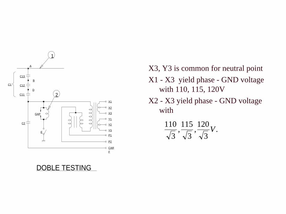
X3, Y3 is common for neutral pointX1 - X3 yield phase - GND voltage
with 110, 115, 120VX2 - X3 yield phase - GND voltage
with
A
B
D
C1
C13
C12
C11
C2
GAP
E
X1
X2
X3
Y1
Y2
Y3
P1
P2
CARF
1
2
DOBLE TESTING
.3
120,3
115,3
110 V
Rating and Specifications
• Rated Voltage / Frequency e.g. 230 KV / 50Hz• Maximum Service Voltage e.g. 242 KV• Insulation Level
– 1 Minute Power Frequency e.g. 525 KV– BIL e.g. 900 KV
• Creepage Distance of Insulator e.g. 6600 mm.• Secondary Voltage e.g. 119.5/69 V, 119.5/69 V (138KV Ref)• Burden