Hybrid Circuits with Nanofluidic Diodes and Load Capacitors
P. Ramirez,1,* V. Garcia-Morales,1 V. Gomez,1 M. Ali,2,3 S. Nasir,3 W. Ensinger,2,3 and S. Mafe41Departament de Física Aplicada, Universitat Politècnica de València, E-46022 València, Spain
2Department of Material- and Geo-Sciences, Materials Analysis, Technische Universität Darmstadt,D-64287 Darmstadt, Germany
3Materials Research Department, GSI Helmholtzzentrum für Schwerionenforschung,D-64291 Darmstadt, Germany
4Departament de Física de la Terra i Termodinàmica, Universitat de València, E-46100 Burjassot, Spain(Received 29 March 2017; revised manuscript received 26 May 2017; published 30 June 2017)
The chemical and physical input signals characteristic of micro- and nanofluidic devices operating inionic solutions should eventually be translated into output electric currents and potentials that aremonitored with solid-state components. This crucial step requires the design of hybrid circuits showingrobust electrical coupling between ionic solutions and electronic elements. We study experimentally andtheoretically the connectivity of the nanofluidic diodes in single-pore and multipore membranes withconventional capacitor systems for the cases of constant, periodic, and white-noise input potentials. Theexperiments demonstrate the reliable operation of these hybrid circuits over a wide range of membraneresistances, electrical capacitances, and solution pH values. The model simulations are based on empiricalequations that have a solid physical basis and provide a convenient description of the electrical circuitoperation. The results should contribute to advance signal transduction and processing using nanopore-based biosensors and bioelectronic interfaces.
DOI: 10.1103/PhysRevApplied.7.064035
I. INTRODUCTION
Micro- and nanofluidic devices operating in ionicsolutions allow a wide range of functionalities becauseof the different pore-surface functionalizations currentlyavailable [1–4]. The interaction between the ions and thespecific molecules functionalized on the pore surface ofthese soft nanostructures can be externally modulated bymeans of thermal, chemical, electrical, and optical signals[1–4]. The different nature of these input signals is crucialin applications such as electrochemical energy conversion,logic responses in sensors and actuators, and signalprocessing in bioelectrical interfaces [1,5–7]. However,to achieve full functionality, the physical responses atthe nanoscale should eventually be translated into electriccurrent and potential signals that are monitored with solid-state components. Therefore, significant physical advancesrequire an efficient electrical coupling between the nano-fluidic devices and conventional electronic elements suchas capacitors in hybrid circuits.We have studied recently the conversion of white-noise,
zero average electrical potentials into net currents by usingsingle nanofluidic diodes [8] and protein ion channels [9].To check further the connectivity between these liquid-statenanostructures and conventional capacitor systems, wepropose now to study experimentally and theoretically
some fundamental theorems concerning energy conversionand charge transfer in hybrid networks.The experimental results concern single-pore and multi-
pore membranes and show the reliable operation of circuitswhere different load capacitors are interconnected with softnanostructures that act as potential-dependent resistances.We propose also a physically motivated empirical equationfor the current-voltage curves of the nanofluidic diodes thatpermits the analysis of hybrid circuits similar as in the caseof conventional solid-state circuits. For the sake of general-ity, we use constant, periodic, and white-noise inputpotential signals. The membrane resistances are between1 kΩ and 1 GΩ and the capacitances of the load capacitorsvary between 10 nF and 10 mF. The electrolyte solutionproperties cover a wide range of pH values between 1and 9, approximately. Because of the wide range ofphysical and chemical conditions considered, the exper-imental and theoretical results should contribute to advancesignal transduction and processing using nanopore-basedbiosensors and bioelectronic interfaces [1,5,7–10].
II. EXPERIMENTAL METHODS
A. Nanofluidic diode fabrication
We use membrane samples with 1 and 104 tracks per cm2
obtained from stacks of 12.5-μm-thick polyimide (PI) foils(Kapton50 HN, DuPont) irradiated with swift heavy ions(Au) of energy 11.4 MeV per nucleon under normalincidence at the linear accelerator UNILAC (GSI,Darmstadt). Under these conditions, the range of heavy*[email protected]
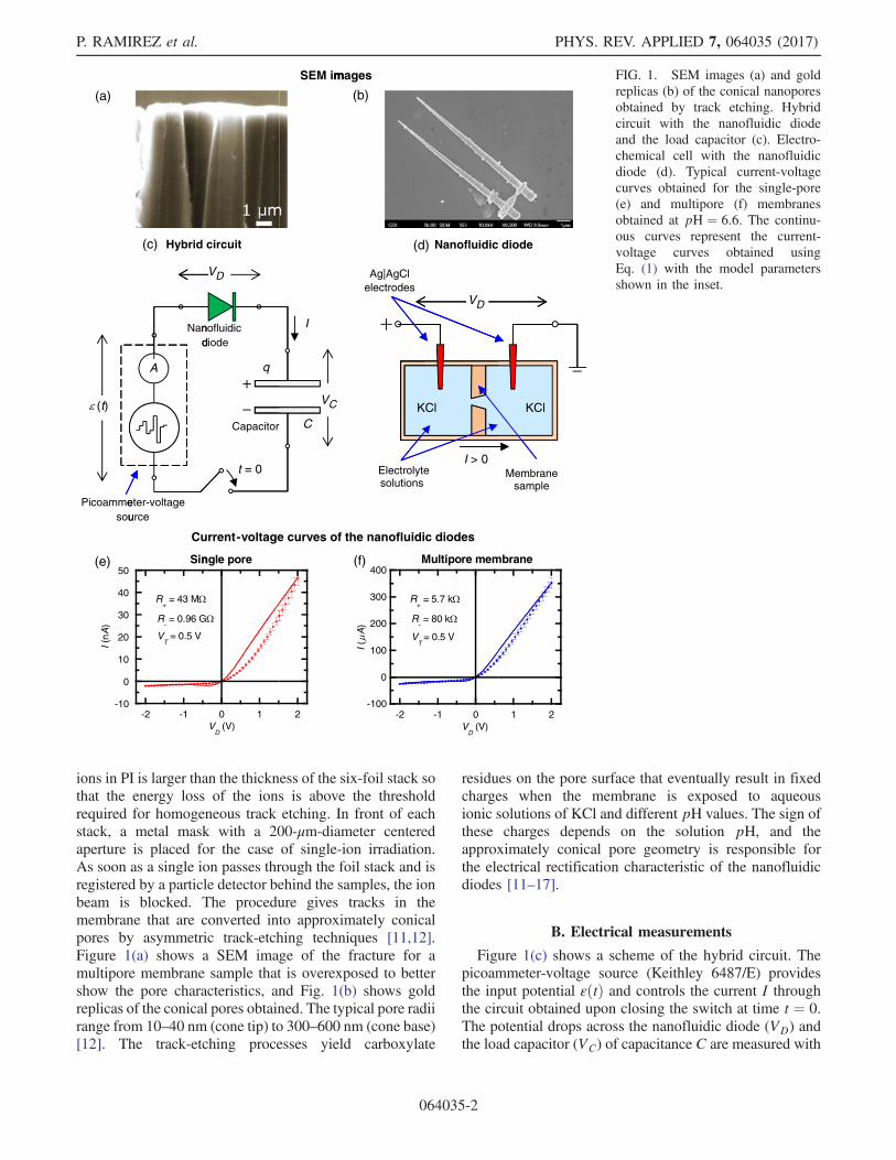
ions in PI is larger than the thickness of the six-foil stack sothat the energy loss of the ions is above the thresholdrequired for homogeneous track etching. In front of eachstack, a metal mask with a 200-μm-diameter centeredaperture is placed for the case of single-ion irradiation.As soon as a single ion passes through the foil stack and isregistered by a particle detector behind the samples, the ionbeam is blocked. The procedure gives tracks in themembrane that are converted into approximately conicalpores by asymmetric track-etching techniques [11,12].Figure 1(a) shows a SEM image of the fracture for amultipore membrane sample that is overexposed to bettershow the pore characteristics, and Fig. 1(b) shows goldreplicas of the conical pores obtained. The typical pore radiirange from 10–40 nm (cone tip) to 300–600 nm (cone base)[12]. The track-etching processes yield carboxylate
residues on the pore surface that eventually result in fixedcharges when the membrane is exposed to aqueousionic solutions of KCl and different pH values. The sign ofthese charges depends on the solution pH, and theapproximately conical pore geometry is responsible forthe electrical rectification characteristic of the nanofluidicdiodes [11–17].
B. Electrical measurements
Figure 1(c) shows a scheme of the hybrid circuit. Thepicoammeter-voltage source (Keithley 6487/E) providesthe input potential εðtÞ and controls the current I throughthe circuit obtained upon closing the switch at time t ¼ 0.The potential drops across the nanofluidic diode (VD) andthe load capacitor (VC) of capacitance C are measured with
(e)
Picoammesou
(t)
(a)
-10
0
10
20
30
40
50
I (nA
)
Current-voltage curves of the nanofluidic diodes
Nand
Hybrid circuit
eter-voltage urce
(c)
-2 -1
Sin
R+ = 43 M
R- = 0.96 G
VT
= 0.5 V
A
Capacitor
nofluidic diode
q
t = 0
VD
0 1
ngle pore
VD (V)
C
VC
I
SEM im
2
(f)
Ag|AgCl electrodes
Electrolyte solutions
(d)
(b)
mages
KC
-100
0
100
200
300
400
-2
Multipore membrane
I (A
)
R+
=
R-=
VT
=
Nanofluidic diode
VD
I > 0
Cl
-1 0V
D (V)
= 5.7 k
= 80 k
= 0.5 V
Membranesample
KClKCl
1 2
FIG. 1. SEM images (a) and goldreplicas (b) of the conical nanoporesobtained by track etching. Hybridcircuit with the nanofluidic diodeand the load capacitor (c). Electro-chemical cell with the nanofluidicdiode (d). Typical current-voltagecurves obtained for the single-pore(e) and multipore (f) membranesobtained at pH ¼ 6.6. The continu-ous curves represent the current-voltage curves obtained usingEq. (1) with the model parametersshown in the inset.
P. RAMIREZ et al. PHYS. REV. APPLIED 7, 064035 (2017)
064035-2
a multimeter (Keithley 2000/E). Figure 1(d) shows ascheme of the electrochemical cell with the nanofluidicdiode for the single-pore-membrane case. The membranearea exposed to the aqueous ionic solutions is 1 cm2. Themembrane samples are bathed by 0.1-M KCl electrolytesolutions under controlled-pH conditions. AgjAgCl elec-trodes immersed in the bathing solutions are employed tointroduce the input potentials in the electrochemical celland measure the electric currents. Note the sign criteriaused for voltages and currents.Figures 1(e) and 1(f) show typical current-voltage (I-VD)
curves obtained for the single-pore and multipore mem-branes, respectively. The curves show current rectificationcharacteristics: low pore resistances are obtained when thecurrent enters the cone tip (VD > 0), while high resistancesare observed when the current enters the cone base(VD < 0). The reproducibility of the nanopore I-VD curvesand the membrane responses is checked several times in allexperiments conducted with the different circuits, and theresulting error bars are included in Figs. 1(e) and 1(f).
III. MODEL
Ionic transport processes through conical nanoporeshave been studied intensively during the past decade[1,3,12–17]. Most of the proposed models are based onthe Poisson-Nernst-Planck equations that allow for thecalculation of the I-VD curves in terms of the poregeometry, the surface concentration of the fixed charges,and the concentrations and the diffusion coefficients of theelectrolyte ions [12,17]. Although these models provide anaccurate description of single pores, the calculationsinvolve complicated numerical schemes which make thisapproach unsuitable for the practical analysis of hybridcircuits composed of multiple interconnected elements. Asa simplified alternative, we propose here a physicallymotivated empirical equation for IðVDÞ:
I ¼ VD
2rRþ
�rþ 1þ ðr − 1Þ tanh
�VD
VT
��; ð1Þ
where r≡ R−=Rþ is the ratio of the resistances Rþ and R−experimentally observed for high positive and negativevoltages, respectively. For high positive VD, Eq. (1) givesI ≈ VD=Rþ asymptotically, while for high negative voltagesVD, it reduces to I ≈ VD=R− The parameter VT describesthe electrical sharpness of the transition between these twoOhmic regimes. The continuous lines in Figs. 1(e)and 1(f) are the results obtained from Eq. (1) using theparameters shown in the inset. This approach should be validfor not too high voltages and allows for the use of standardmethods of circuit analysis while keeping the number of freeparameters to a minimum. In addition, the use of Eq. (1)permits us to obtain quantitative predictions for the hybridcircuits described in the following section.
IV. RESULTS AND DISCUSSION
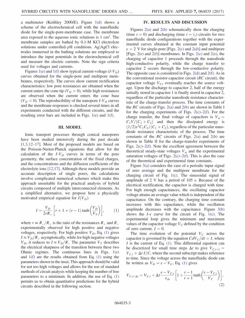
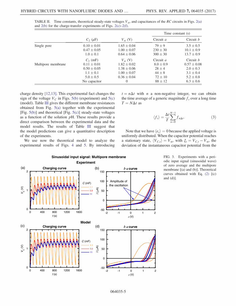
Figures 2(a) and 2(b) schematically show the charging(time t ¼ 0) and discharging (time t ¼ ts) circuits for twonanofluidic diode configurations together with the exper-imental curves obtained at the constant input potentialε ¼ 2 V for single-pore [Figs. 2(c) and 2(d)] and multipore[Figs. 2(e) and 2(f)] membranes. In Figs. 2(c) and 2(e), thecharging of capacitor 1 proceeds through the nanodiodehigh-conductive polarity, while the charge transfer tocapacitor 2 occurs through the low-conductive polarity.The opposite case is considered in Figs. 2(d) and 2(f). As inthe conventional resistor-capacitor circuit (RC circuit), thecapacitor voltage VC1 eventually reaches the source volt-age. Upon the discharge to capacitor 2, half of the energyinitially stored in capacitor 1 is finally stored in capacitor 2,regardless of the particular nanodiode resistance character-istic of the charge-transfer process. The time constants ofthe RC circuits of Figs. 2(a) and 2(b) are shown in Table Ifor the charging experiments of Figs. 2(c)–2(f). For thecharge transfer, the final voltage of capacitors is Vst ¼C1V=ðC1 þ C2Þ and then the dissipated energy isð1=2Þε2C1C2=ðC1 þ C2Þ, regardless of the particular nano-diode resistance characteristic of the process. The timeconstants of the RC circuits of Figs. 2(a) and 2(b) areshown in Table II for the charge-transfer experiments ofFigs. 2(c)–2(f). Note the excellent agreement between thetheoretical steady-state voltages Vst and the experimentalsaturation voltages of Figs. 2(c)–2(f). This is also the caseof the theoretical and experimental time constants.Figure 3(a) considers the case of a periodic input signal
of zero average and the multipore membrane for thecharging circuit of Fig. 1(c). The sinusoidal signal ofamplitude of 2 V has a period of 105 s. Because of theelectrical rectification, the capacitor is charged with time.For high enough capacitances, the oscillating capacitorvoltage attains an average value which is independent of thecapacitance. On the contrary, the charging time constantincreases with this capacitance, while the oscillationamplitude decreases with the capacitance. Figure 3(b)shows the I-ε curve for the circuit of Fig. 1(c). Theexperimental loop gives the minimum and maximumvalues of the capacitor voltage VC defined by the conditionof zero current, I ¼ 0.The time evolution of the potential VC across the
capacitor is governed by the equation CdVC=dt ¼ I, whereI is the current of Eq. (1). This differential equation canbe discretized for small time steps Δt to give VC;tþ1 ¼VC;t þ Δt I=C, where the second subscript makes referenceto time. Since the voltage across the nanofluidic diode canbe written as VD ¼ ε − VC, Eq. (1) gives
VC;tþΔt ¼ VC;t þΔtε− VC;t
τch
�1þ r− 1
rþ 1tanh
�ε− VC;t
VT
��;
ð2Þ
HYBRID CIRCUITS WITH NANOFLUIDIC DIODES AND … PHYS. REV. APPLIED 7, 064035 (2017)
064035-3
where we introduce the characteristic time τch ≡½2r=ðrþ 1Þ�RþC. Figures 3(c) and 3(d) show that thetheoretical curves obtained with Eq. (2) are in goodagreement with the experiments. The small differencesbetween the theoretical and the experimental curvesarise from the approximated equation used for IðVDÞ[see Figs. 1(e) and 1(f)].Figure 4 shows the case of thewhite-noise input signal for
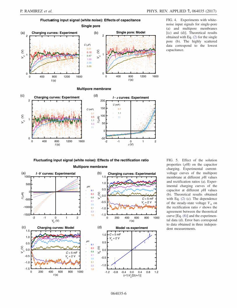
single-pore [Figs. 4(a) and 4(b)] and multipore [Figs. 4(c)and 4(d)] membranes. This case is of interest for energytransduction using external noisy signals [8,9]. As observedpreviously in the case of the periodic input signal (Fig. 3), the
limiting value of the capacitor voltage does not change withthe capacitance [see Figs. 4(a)–4(c)], which is not the case ofthe time constants and the fluctuating potential amplitudesaround the average potential. The theoretical results ofFig. 4(b) are obtained introducing in Eq. (2) a voltage εtthat takes random values in the interval ½−V0; V0� at eachtime step according to a uniform distribution. Figure 4(d)shows the I-ε curve for the circuit of Fig. 1(c) in the case ofthe multipore membrane. The minimum and maximumvalues of the capacitor voltage VC are now approximatelydescribed by the condition of zero current, I ¼ 0. Theamplitude between the extreme values of Fig. 4(d) approx-imately corresponds to the difference between the minimumand maximum fluctuating potentials of Fig. 4(c).Figure 5 considers the effect of the solution properties
(pH) on the I-VD curves [Fig. 5(a)], the charging process[Figs. 5(b) and 5(c)], and the dependence of the steady-statevoltage Vst on the rectification ratio r [Fig. 5(d)]. Note theeffect of the pore fixed-charge sign on the I-VD curves:decreasing the pH causes a decrease in the negative surfacecharge density and eventually reverses it to give a positive
Charging circuitCharging circuit
C1I
t = 0
(a)
0.0
0.5
1.0
1.5
2.0
0 400 800 1200 1600t (s)
VC
1 (V
)
C1 = 0.47 F
0.0
0.5
1.0
1.5
2.0
0 400 800 1200 1600
0.10
0.47
1.00
t (s)
VC
1 (V
)
C2 ( F)
VC1
C1C2
t = ts
I
Charge transfer
VC1
C1I
t = 0
(b)
VC1
C1C2
t = ts
I
Charge transfer
VC1
(c)
0.0
0.5
1.0
1.5
2.0
0 200 400 600 800
VC
1 (V
)
t (s)
C1 = 1.1 mF
0.0
0.5
1.0
1.5
2.0
0 200 400 600 800
0.11
0.5
1.1
5.0
No C2
VC
1 (V
)
t (s)
C2 (mF)
(e) (f)
Single pore: Experiment
(d)
Multipore membrane: Experiment
Circuit schemes FIG. 2. The charging and discharg-ing (charge transfer between capaci-tors) circuits for two nanofluidic diodeconfigurations (a) and (b). Experi-mental curves measured for single-pore membrane [(c) and (d)]. Thecurves correspond to C2 ¼ 0.10,0.47, and 1.0 μF, from top to bottom.Experimental curves measured formultipore membrane [(e) and (f)].The curves correspond to C2 ¼ 0.11,0.5, 1.1, 5.0, and 0 mF, from top tobottom. All curves are obtained withconstant input potential ε ¼ 2 V.
TABLE I. Time constants for the RC circuits of Figs. 2(a)and 2(b) in the charging experiments of Figs. 2(c)–2(f).
P. RAMIREZ et al. PHYS. REV. APPLIED 7, 064035 (2017)
064035-4
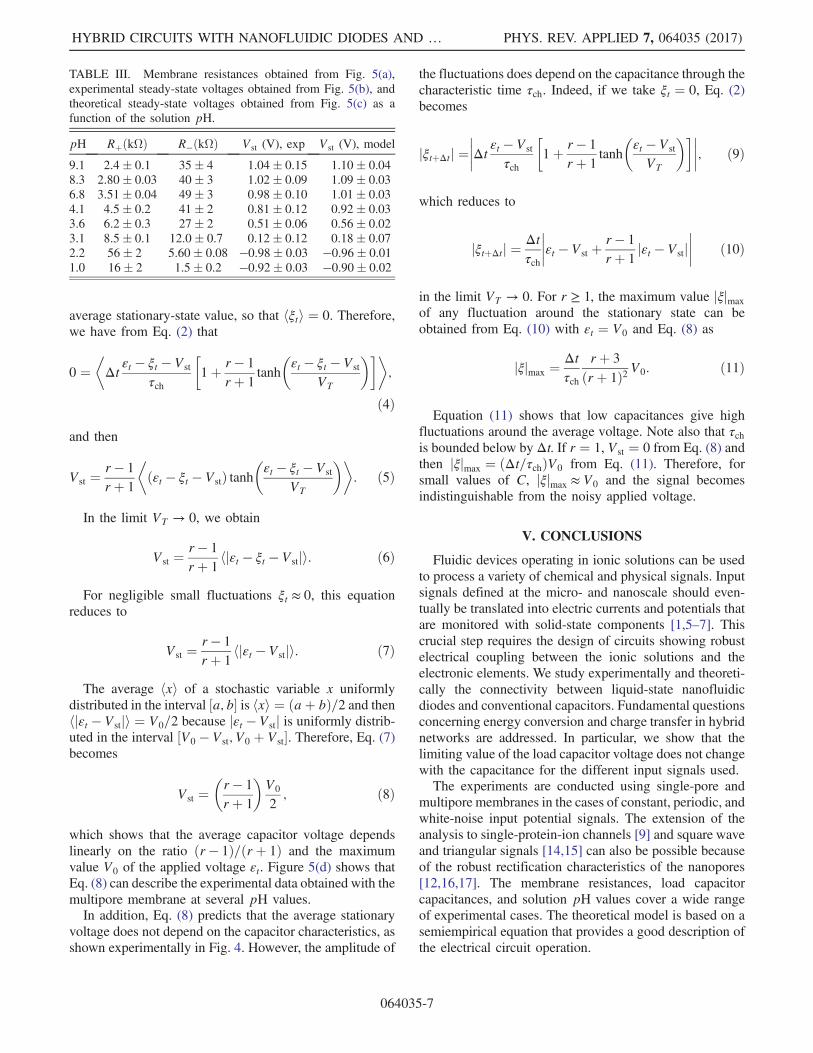
charge density [12,13]. This experimental fact changes thesign of the voltage VC in Figs. 5(b) (experiment) and 5(c)(model). Table III gives the different membrane resistancesobtained from Fig. 5(a) together with the experimental[Fig. 5(b)] and theoretical [Fig. 5(c)] steady-state voltagesas a function of the solution pH. These results provide adirect comparison between the experimental data and themodel results. The results of Table III suggest thatthe model predictions can give a quantitative descriptionof the experiments.We use now the theoretical model to analyze the
experimental results of Figs. 4 and 5. By introducing
t ¼ nΔt with n a non-negative integer, we can obtainthe time average of a generic magnitude ft over a long timeT ¼ NΔt as
hfti ¼ΔtT
XN−1
n¼0
fnΔt: ð3Þ
Note that we have hεti ¼ 0 because the applied voltage isuniformly distributed. When the capacitor potential reachesa stationary state, hVC;ti ¼ Vst, with ξt ¼ VC;t − Vst, thedeviation of the instantaneous capacitor potential from the
TABLE II. Time constants, theoretical steady-state voltages Vst, and capacitances of the RC circuits in Figs. 2(a)and 2(b) for the charge-transfer experiments of Figs. 2(c)–2(f).
FIG. 3. Experiments with a peri-odic input signal (sinusoidal wave)of zero average and the multiporemembrane [(a) and (b)]. Theoreticalcurves obtained with Eq. (2) [(c)and (d)].
HYBRID CIRCUITS WITH NANOFLUIDIC DIODES AND … PHYS. REV. APPLIED 7, 064035 (2017)
064035-5
(a)
(c)
0
1
2
0
0
1
2
400
Charging cur
0 400
Charging cu
Fluctua
800 1200
rves: Experim
800 1200
urves: Experiment
ating input si
1600
ent
0.01
0.10
0.47
1.00
2.35
5.00
C ( F)
1600
0.
0.5
1.
5.0
11
C (mF)
Single p
Multipore
gnal (white n
1
5
1
0
)
(b)
(d)
-50
0
50
100
150
200
-2
II(
A)
C
ore
membrane
noise): Effects
0
1
2
0
-1 0
- curves: Experiment
0.1
1.1
11
(V)
C (mF)
of capacitance
400 800
Single pore:
t (s)t (s)
t (s)1 2
1200 160
Model
2
00
VC
(V
)
VC
(V
)V
C (
V)
FIG. 4. Experiments with white-noise input signals for single-pore(a) and multipore membranes[(c) and (d)]. Theoretical resultsobtained with Eq. (2) for the singlepore (b). The highly scattereddata correspond to the lowestcapacitance.
-1500
-1000
-500
0
500
1000
-2 -1 0 1 2
I -V curves: Experimental
9.1
8.3
6.8
4.1
3.6
3.1
2.2
1.0
I(A
)
pH
pH
VD
(V)
-1.5
-1.0
-0.5
0.0
0.5
1.0
1.5
0 200 400 600 800 1000
Charging curves: Model
9.1
8.3
6.8
4.1
3.6
3.1
2.2
1.0
VC (
V)
t (s)
C = 5 mFV
0 = 2 V
Fluctuating input signal (white noise): Effects of the rectification ratio
Multipore membrane
(a)
(c)
(b)
(d)
-1.5
-1.0
-0.5
0.0
0.5
1.0
1.5
0 200 400 600 800 1000
Charging curves: Experimental
VC (
V)
t (s)
C = 5 mFV
0 = 2 V
-1.0
-0.5
0.0
0.5
1.0
-1.2 -0.8 -0.4 0.0 0.4 0.8 1.2
Model vs experiment
V st (
V)
(r-1)V0/[2(r+1)]
C = 5 mFV
0 = 2 V
FIG. 5. Effect of the solutionproperties (pH) on the capacitorcharging. Experimental current-voltage curves of the multiporemembrane at different pH valuesand rectification ratios (a). Exper-imental charging curves of thecapacitor at different pH values(b). Theoretical results obtainedwith Eq. (2) (c). The dependenceof the steady-state voltage Vst onthe rectification ratio r shows theagreement between the theoreticalcurve [Eq. (8)] and the experimen-tal data (d). Error bars correspondto data obtained in three indepen-dent measurements.
P. RAMIREZ et al. PHYS. REV. APPLIED 7, 064035 (2017)
064035-6
average stationary-state value, so that hξti ¼ 0. Therefore,we have from Eq. (2) that
0 ¼�Δt
εt − ξt − Vst
τch
�1þ r − 1
rþ 1tanh
�εt − ξt − Vst
VT
���;
ð4Þ
and then
Vst ¼r − 1
rþ 1
�ðεt − ξt − VstÞ tanh
�εt − ξt − Vst
VT
��: ð5Þ
In the limit VT → 0, we obtain
Vst ¼r − 1
rþ 1hjεt − ξt − Vstji: ð6Þ
For negligible small fluctuations ξt ≈ 0, this equationreduces to
Vst ¼r − 1
rþ 1hjεt − Vstji: ð7Þ
The average hxi of a stochastic variable x uniformlydistributed in the interval ½a; b� is hxi ¼ ðaþ bÞ=2 and thenhjεt − Vstji ¼ V0=2 because jεt − Vstj is uniformly distrib-uted in the interval ½V0 − Vst; V0 þ Vst�. Therefore, Eq. (7)becomes
Vst ¼�r − 1
rþ 1
�V0
2; ð8Þ
which shows that the average capacitor voltage dependslinearly on the ratio ðr − 1Þ=ðrþ 1Þ and the maximumvalue V0 of the applied voltage εt. Figure 5(d) shows thatEq. (8) can describe the experimental data obtained with themultipore membrane at several pH values.In addition, Eq. (8) predicts that the average stationary
voltage does not depend on the capacitor characteristics, asshown experimentally in Fig. 4. However, the amplitude of
the fluctuations does depend on the capacitance through thecharacteristic time τch. Indeed, if we take ξt ¼ 0, Eq. (2)becomes
jξtþΔtj ¼����Δt εt − Vst
τch
�1þ r − 1
rþ 1tanh
�εt − Vst
VT
������; ð9Þ
which reduces to
jξtþΔtj ¼Δtτch
����εt − Vst þr − 1
rþ 1jεt − Vstj
���� ð10Þ
in the limit VT → 0. For r ≥ 1, the maximum value jξjmaxof any fluctuation around the stationary state can beobtained from Eq. (10) with εt ¼ V0 and Eq. (8) as
jξjmax ¼Δtτch
rþ 3
ðrþ 1Þ2 V0: ð11Þ
Equation (11) shows that low capacitances give highfluctuations around the average voltage. Note also that τchis bounded below by Δt. If r ¼ 1, Vst ¼ 0 from Eq. (8) andthen jξjmax ¼ ðΔt=τchÞV0 from Eq. (11). Therefore, forsmall values of C, jξjmax ≈ V0 and the signal becomesindistinguishable from the noisy applied voltage.
V. CONCLUSIONS
Fluidic devices operating in ionic solutions can be usedto process a variety of chemical and physical signals. Inputsignals defined at the micro- and nanoscale should even-tually be translated into electric currents and potentials thatare monitored with solid-state components [1,5–7]. Thiscrucial step requires the design of circuits showing robustelectrical coupling between the ionic solutions and theelectronic elements. We study experimentally and theoreti-cally the connectivity between liquid-state nanofluidicdiodes and conventional capacitors. Fundamental questionsconcerning energy conversion and charge transfer in hybridnetworks are addressed. In particular, we show that thelimiting value of the load capacitor voltage does not changewith the capacitance for the different input signals used.The experiments are conducted using single-pore and
multipore membranes in the cases of constant, periodic, andwhite-noise input potential signals. The extension of theanalysis to single-protein-ion channels [9] and square waveand triangular signals [14,15] can also be possible becauseof the robust rectification characteristics of the nanopores[12,16,17]. The membrane resistances, load capacitorcapacitances, and solution pH values cover a wide rangeof experimental cases. The theoretical model is based on asemiempirical equation that provides a good description ofthe electrical circuit operation.
TABLE III. Membrane resistances obtained from Fig. 5(a),experimental steady-state voltages obtained from Fig. 5(b), andtheoretical steady-state voltages obtained from Fig. 5(c) as afunction of the solution pH.
HYBRID CIRCUITS WITH NANOFLUIDIC DIODES AND … PHYS. REV. APPLIED 7, 064035 (2017)
064035-7
ACKNOWLEDGMENTS
We acknowledge the support from the Ministry ofEconomic Affairs and Competitiveness and FEDER(Project No. MAT2015-65011-P). M. A., S. N., andW. E. acknowledge the funding from the Hessen StateMinistry of Higher Education, Research and the Arts,Germany, under the LOEWE project iNAPO.
[1] M. Tagliazucchi and I. Szleifer, Transport mechanismsin nanopores and nanochannels: Can we mimic nature?,Mater. Today 18, 131 (2015).
[2] Q. Liu, L. Wen, K. Xiao, H. Lu, Z. Zhang, G. Xie, X.-Y.Kong, Z. Bo, and L. Jiang, A biomimetic voltage-gatedchloride nanochannel, Adv. Mater. 28, 3181 (2016).
[3] P. Ramirez, J. Cervera, M. Ali, W. Ensinger, and S. Mafe,Logic functions with stimuli-responsive single nanopores,ChemElectroChem 1, 698 (2014).
[4] G. Pérez-Mitta, A. G. Albesa, C. Trautmann, M. E. Toimil-Molares, and O. Azzaroni, Bioinspired integratednanosystems based on solid-state nanopores: “Iontronic”transduction of biological, chemical and physical stimuli,Chem. Sci. 8, 890 (2017).
[5] N. Misra, J. A. Martinez, S.-C. J. Huang, Y. Wang, P.Stroeve, C. P. Grigoropoulos, and A. Noy, Bioelectronicsilicon nanowire devices using functional membrane pro-teins, Proc. Natl. Acad. Sci. U.S.A. 106, 13780 (2009).
[6] Y. Hou, R. Vidu, and P. Stroeve, Solar energy storagemethods, Ind. Eng. Chem. Res. 50, 8954 (2011).
[7] M. Ali, P. Ramirez, W. Ensinger, and S. Mafe, Informationprocessing with a single multifunctional nanofluidic diode,Appl. Phys. Lett. 101, 133108 (2012).
[8] V. Gomez, P. Ramirez, J. Cervera, S. Nasir, M. Ali, W.Ensinger, and S. Mafe, Charging a capacitor from anexternal fluctuating potential using a single conical nano-pore, Sci. Rep. 5, 9501 (2015).
[9] C. Verdia-Baguena, V. Gomez, J. Cervera, P. Ramirez, andS. Mafe, Energy transduction and signal averaging offluctuating electric fields by a single protein ion channel,Phys. Chem. Chem. Phys. 19, 292 (2017).
[10] O. Yehezkeli, R. Tel-Vered, J. Wasserman, A. Trifonov, D.Michaeli, R. Nechushtai, and I. Willner, Integratedphotosystem II-based photo-bioelectrochemical cells, Nat.Commun. 3, 742 (2012).
[11] P. Apel, Track etching technique in membrane technology,Radiation Measurements 34, 559 (2001).
[12] M. Ali, P. Ramirez, S. Mafe, R. Neumann, and W. Ensinger,A pH-tunable nanofluidic diode with a broad range ofrectifying properties, ACS Nano 3, 603 (2009).
[13] J. Cervera, P. Ramirez, V. Gomez, S. Nasir, M. Ali, W.Ensinger, P. Stroeve, and S. Mafe, Multipore membraneswith nanofluidic diodes allowing multifunctional rectifica-tion and logical responses, Appl. Phys. Lett. 108, 253701(2016).
[14] V. Gomez, P. Ramirez, J. Cervera, S. Nasir, M. Ali, W.Ensinger, and S. Mafe, Converting external potential fluc-tuations into nonzero time-average electric currents using asingle nanopore, Appl. Phys. Lett. 106, 073701 (2015).
[15] E. Kalman, K. Healy, and Z. S. Siwy, Tuning ion currentrectification in asymmetric nanopores by signal mixing,Europhys. Lett. 78, 28002 (2007).
[16] Z. Siwy, I. D. Kosińska, A. Fuliński, and C. R. MartinAsymmetric Diffusion through Synthetic Nanopores, Phys.Rev. Lett. 94, 048102 (2005).
[17] Z. S. Siwy and S. Howorka, Engineered voltage-responsivenanopores, Chem. Soc. Rev. 39, 1115 (2010).
P. RAMIREZ et al. PHYS. REV. APPLIED 7, 064035 (2017)


![Circuit Components 1 G6 - CIRCUIT COMPONENTS [3 exam question - 3 groups] G6AResistors; capacitors; inductors G6BRectifiers; solid state diodes and transistors;](https://static.documents.pub/doc/80x56/56649ddc5503460f94ad3e5c/circuit-components-1-g6-circuit-components-3-exam-question-3-groups-g6aresistors.jpg)


