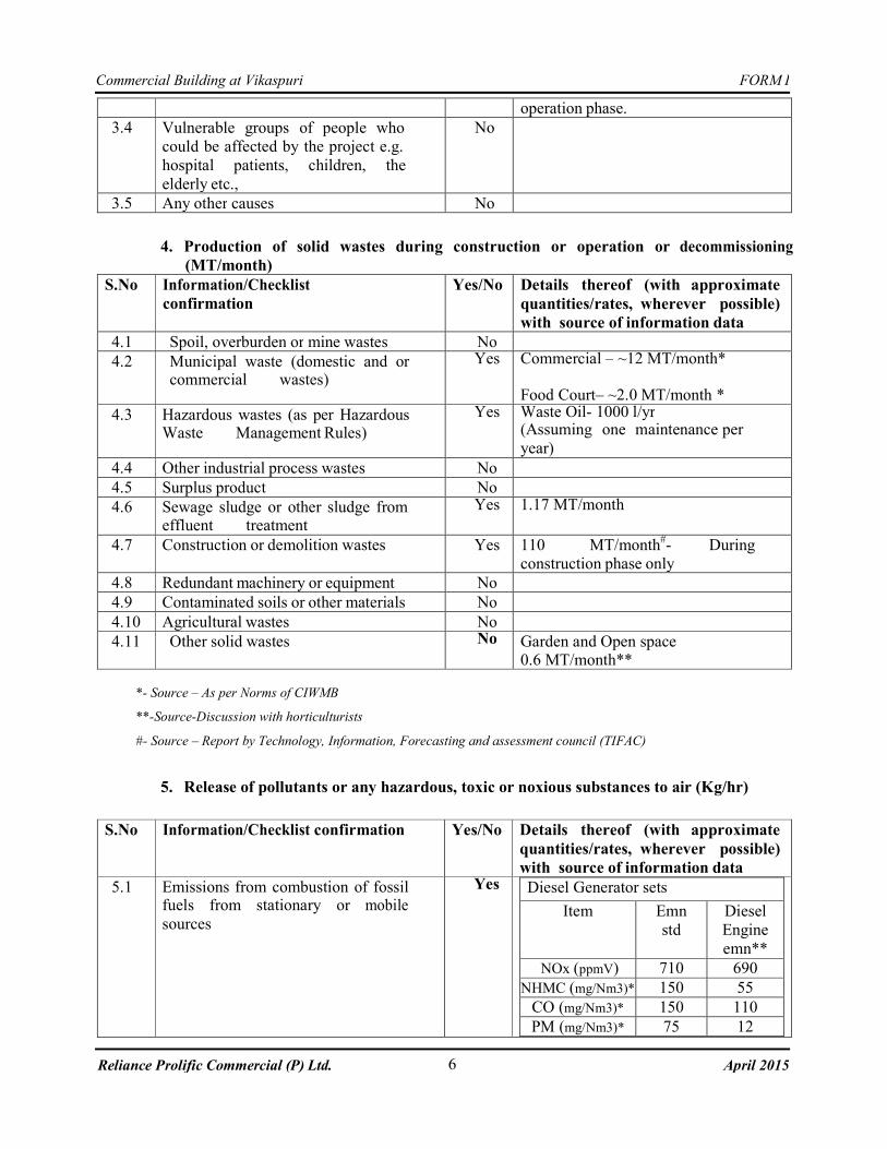
FORM I 1 Commercial Building at Vikaspuri April 2015 Reliance Prolific Commercial (P) Ltd. I. BASIC INFORMATION Name of the Project: COMMERCIAL BUILDING (HYPERMARKET) Location / site alternatives under consideration: The site is located at Plot No. A, Block A, Community Centre, Vikaspuri. Refer ANNEXURE I for site location map and ANNEXURE II for Site surrounding features. Size of the Project: The Campus has spread over an area of 13628 SQM or 1.3628 Hec (Approx.). Expected cost of the project: About 413.09 Crores. Refer ANNEXURE VI for CA Certificate Contact Information: Sh ASHWANI AGARWAL Reliance Prolific Commercial Private Limited, A3, 1st Floor, Mohan Cooperative Industrial Estate, Mathura Road, New Delhi - 110044. Ph: 011-40658201, Mob: 0-9717491991 E-Mail: [email protected]Screening Category: B II. ACTIVITY 1. Construction, operation or decommissioning of the project involving actions, which will cause physical changes in the locality (topography, land use, changes in water bodies, etc.) S.No. Information/Checklist confirmation Yes/No Details thereof (with approximate quantities /rates, wherever possible) with source of information data 1.1 Permanent or temporary change in land use, land cover or topography including increase in intensity of land use (with respect to local land use plan) No The site falls in area Designated as general commercial area or community centre area. The site was previously being used as a construction hub by Delhi Metro Rail Corporation. The site is surrounded by petrol pump and Police station on the western side. 1.2 Clearance of existing land, vegetation and buildings? No The proposed site was being used by Delhi Metro Rail Corporation as a construction hub and does not support any vegetation. 1.3 Creation of new land uses? No The proposed site falls under area designated as general commercial area or community center area. 1.4 Pre-construction investigations e.g.bore houses, soil testing? Yes The details of the geotechnical report are enclosed as ANNEXURE III.
Transcript
FORM I
1
Commercial Building at Vikaspuri
April 2015 Reliance Prolific Commercial (P) Ltd.
I. BASIC INFORMATION
Name of the Project: COMMERCIAL BUILDING
(HYPERMARKET)
Location / site alternatives under consideration: The site is located at Plot No. A, Block A,
Community Centre, Vikaspuri.
Refer ANNEXURE I for site location map and
ANNEXURE II for Site surrounding features.
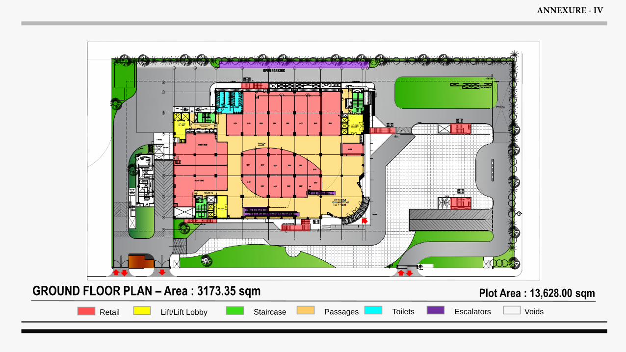
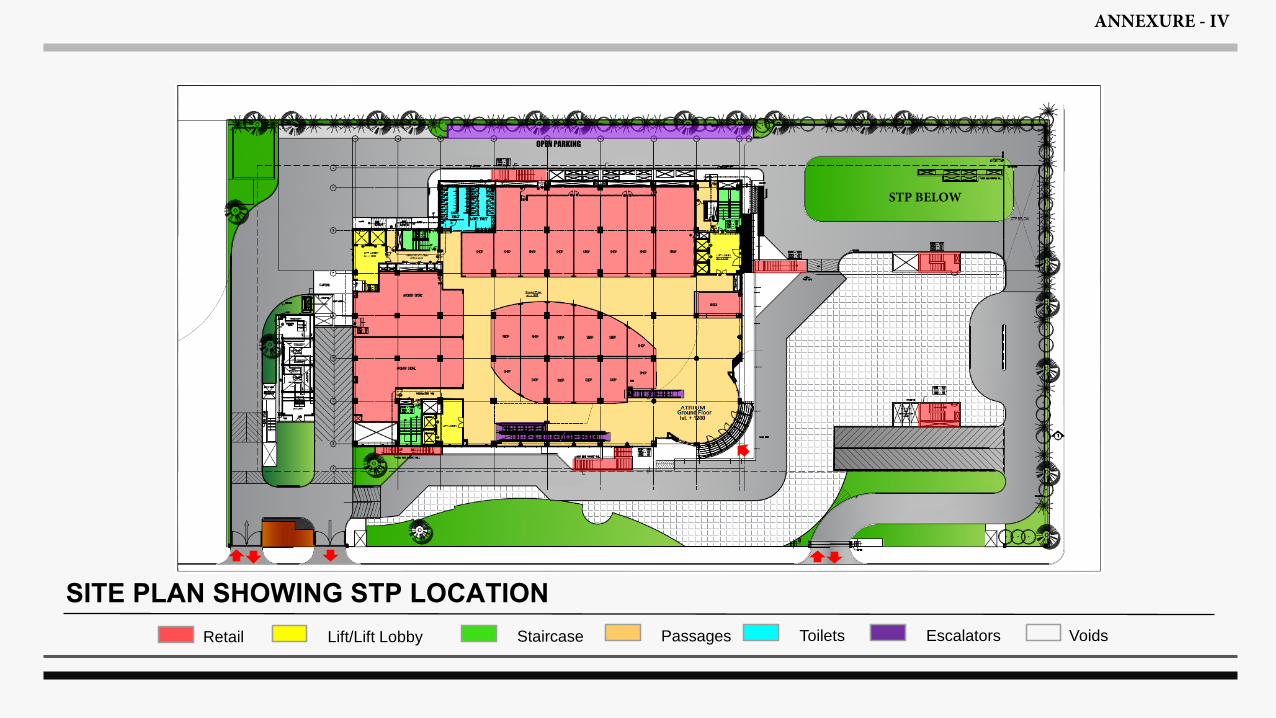
Size of the Project: The Campus has spread over an area of
13628 SQM or 1.3628 Hec (Approx.).
Expected cost of the project: About 413.09 Crores.
TABLE OF CONTENTS Sheet No. 1.0 INTRODUCTION 1 1.1 Project Description 1 1.2 Purposes of Study 1 2.0 FIELD INVESTIGATIONS 1 2.1 Soil Borings 1 2.2 Dynamic Cone Penetration Test 2 2.3 Groundwater 3 3.0 LABORATORY TESTS 3 4.0 GENERAL SITE CONDITIONS 4 4.1 Regional Geology 4 4.2 Site Stratigraphy 4 4.3 Groundwater 5 5.0 FOUNDATION ANALYSIS AND RECOMMENDATIONS 5 5.1 General 5 5.2 Foundation Type and Depth 5 5.3 Open Foundations 6 5.4 Definition of Gross and Net Bearing Pressure 8 5.5 Basement Design 8 5.6 Liquefaction Potential 9 6.0 FOUNDATION CONSTRUCTION CONSIDERATIONS 9 6.1 Excavation 9 6.2 Foundation Level Preparation 10 6.3 Backfilling 10 6.4 Chemical Attack 10 6.5 Variability in Subsurface Conditions 12 7.0 SUMMARY OF PRINCIPAL FINDINGS AND
RECOMMENDATIONS 12
8.0 CLOSURE 13
207020-A iii
CENGRS GEOTECHNICA PVT. LTD. Job No. Sheet No.
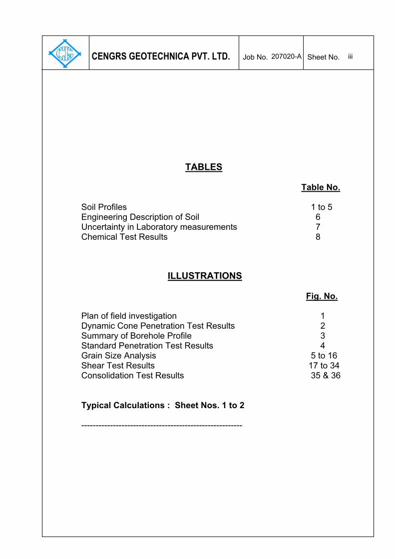
TABLES Table No. Soil Profiles 1 to 5 Engineering Description of Soil 6 Uncertainty in Laboratory measurements 7 Chemical Test Results 8
ILLUSTRATIONS
Fig. No. Plan of field investigation 1 Dynamic Cone Penetration Test Results 2 Summary of Borehole Profile 3 Standard Penetration Test Results 4
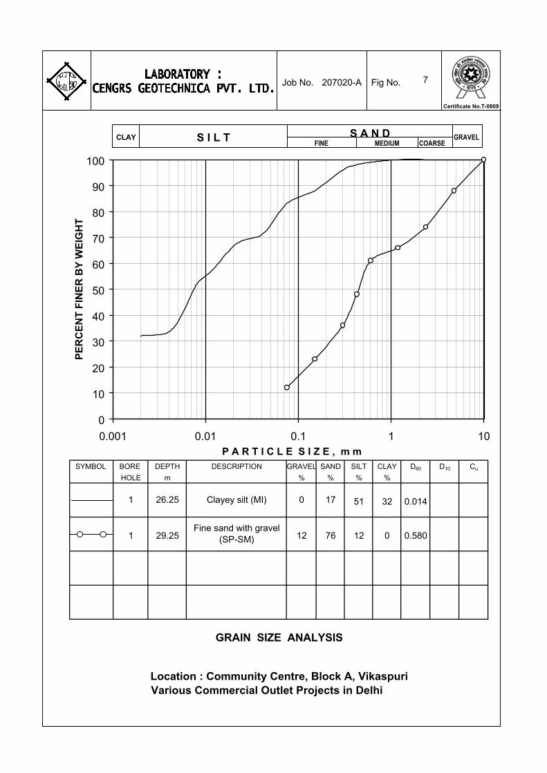
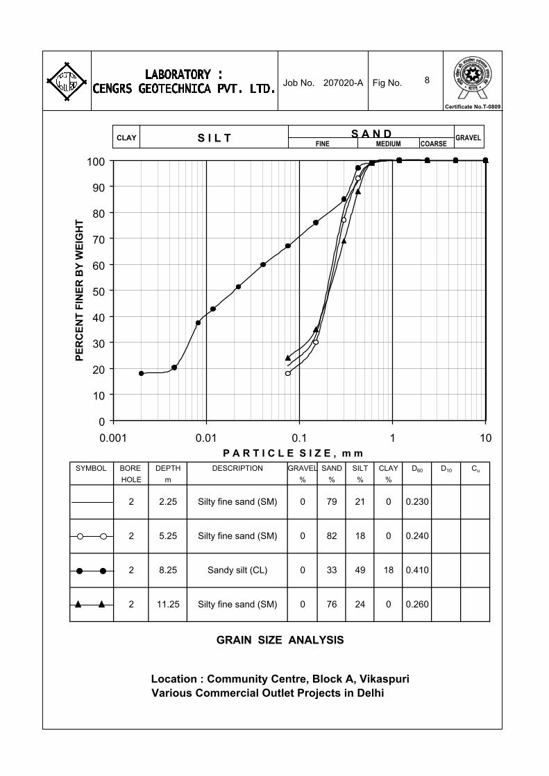
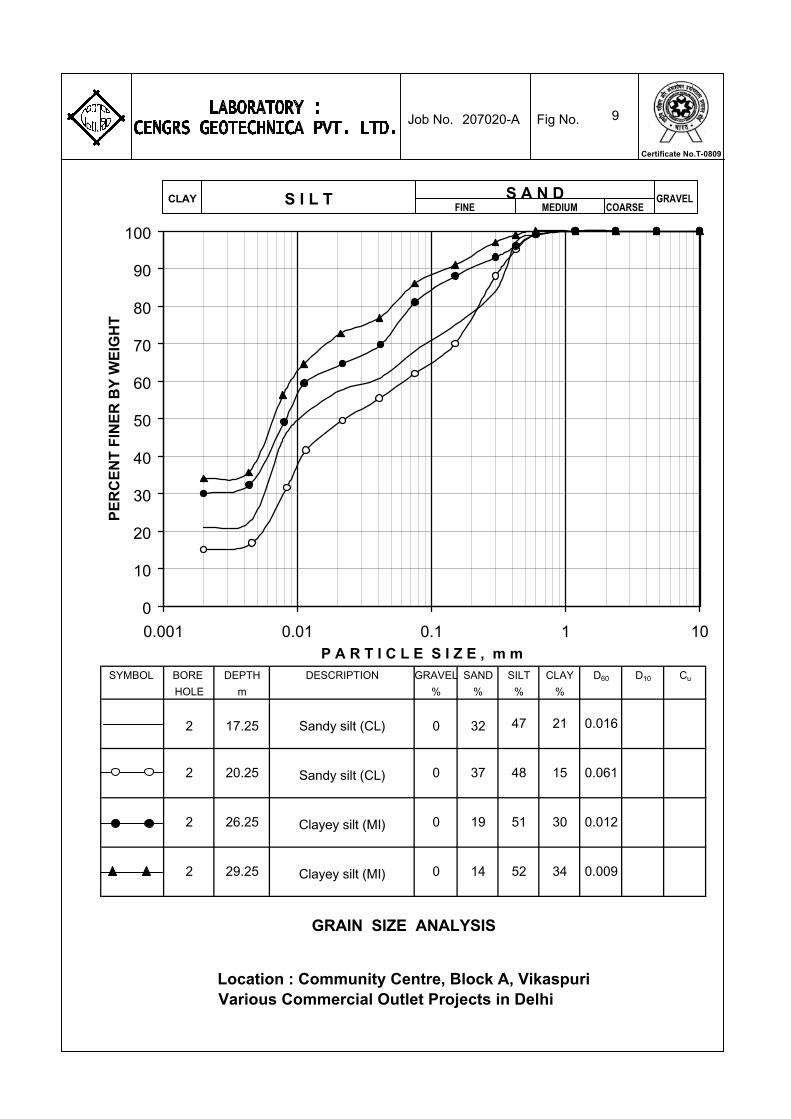
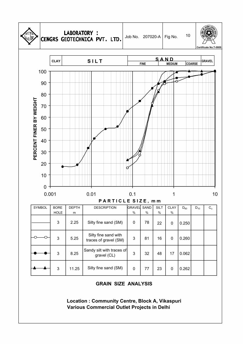
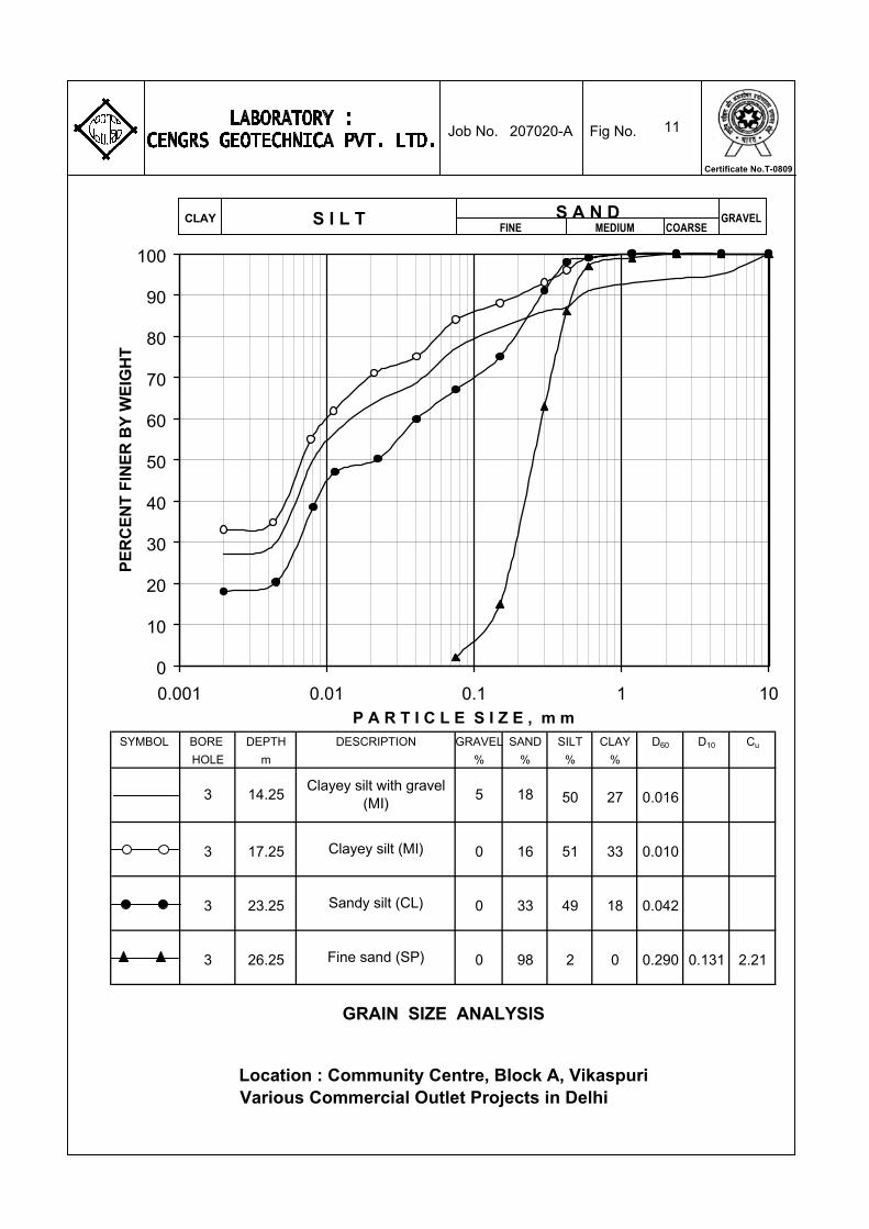
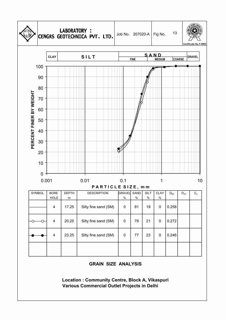
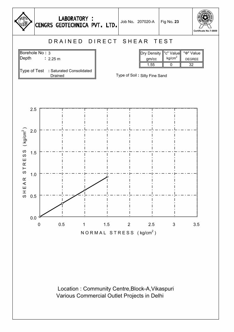
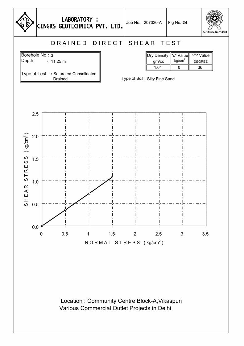
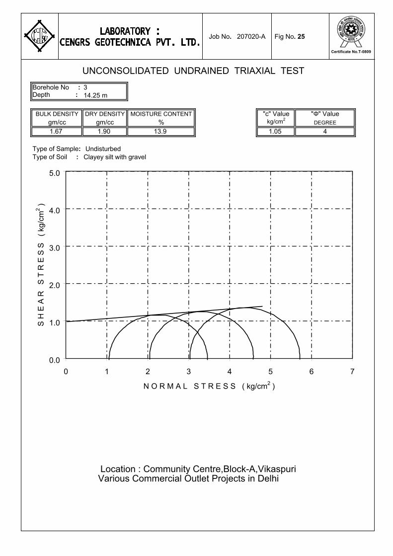
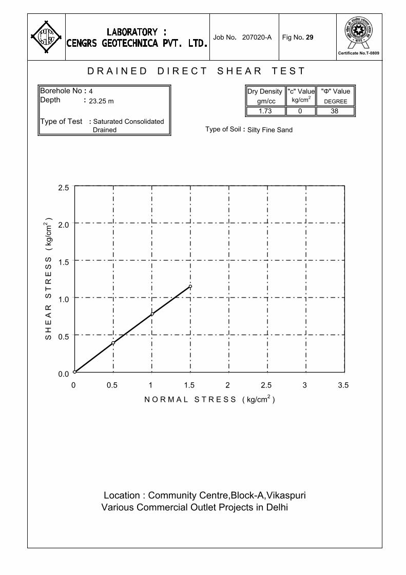
Grain Size Analysis 5 to 16 Shear Test Results 17 to 34 Consolidation Test Results 35 & 36
Typical Calculations : Sheet Nos. 1 to 2 --------------------------------------------------------
207020-A 1
CENGRS GEOTECHNICA PVT. LTD. Job No. Sheet No.
1.0 INTRODUCTION
1.1 Project Description
M/s. Majestic Agrotech(P)Ltd. is planning to construct various Greenfield Commercial Outlet Projects in Delhi.This report presents the results of Community Centre on Plot No. A in Block-A, Vikaspuri, New Delhi.
The plot covers an area of 13628 m2. The ground coverage
shall be 3174 m2 for building and 680 m2 for atrium. The building will have a height of 26 m and shall have three basements. A layout plan showing the locations of our field investigation is illustrated on Fig.1.
1.2 Purposes of Study
The overall purposes of this study are to investigate the stratigraphy at the site and to develop geotechnical recommendations for foundation design and construction. To accomplish these purposes, the study was conducted in the following phases: (a) drilling five boreholes to 30 m depth or refusal whichever is
earlier in order to determine site stratigraphy and to collect disturbed and undisturbed soil samples for laboratory testing;
(b) conducting five dynamic cone penetration tests to 10 m depth or
refusal, so as to obtain additional data for foundation analysis. (c) testing selected soil samples in the laboratory to determine
pertinent index and engineering properties of the soils; and (d) analyzing all field and laboratory data in order to develop
engineering recommendations for foundation design and construction.
2.0 FIELD INVESTIGATION
2.1 Soil Borings The boreholes were progressed using a mechanized shell and auger to the specified depth or refusal, whichever is encountered earlier. The borehole diameter was 150 mm. Where caving of the
207020-A 2
CENGRS GEOTECHNICA PVT. LTD. Job No. Sheet No.
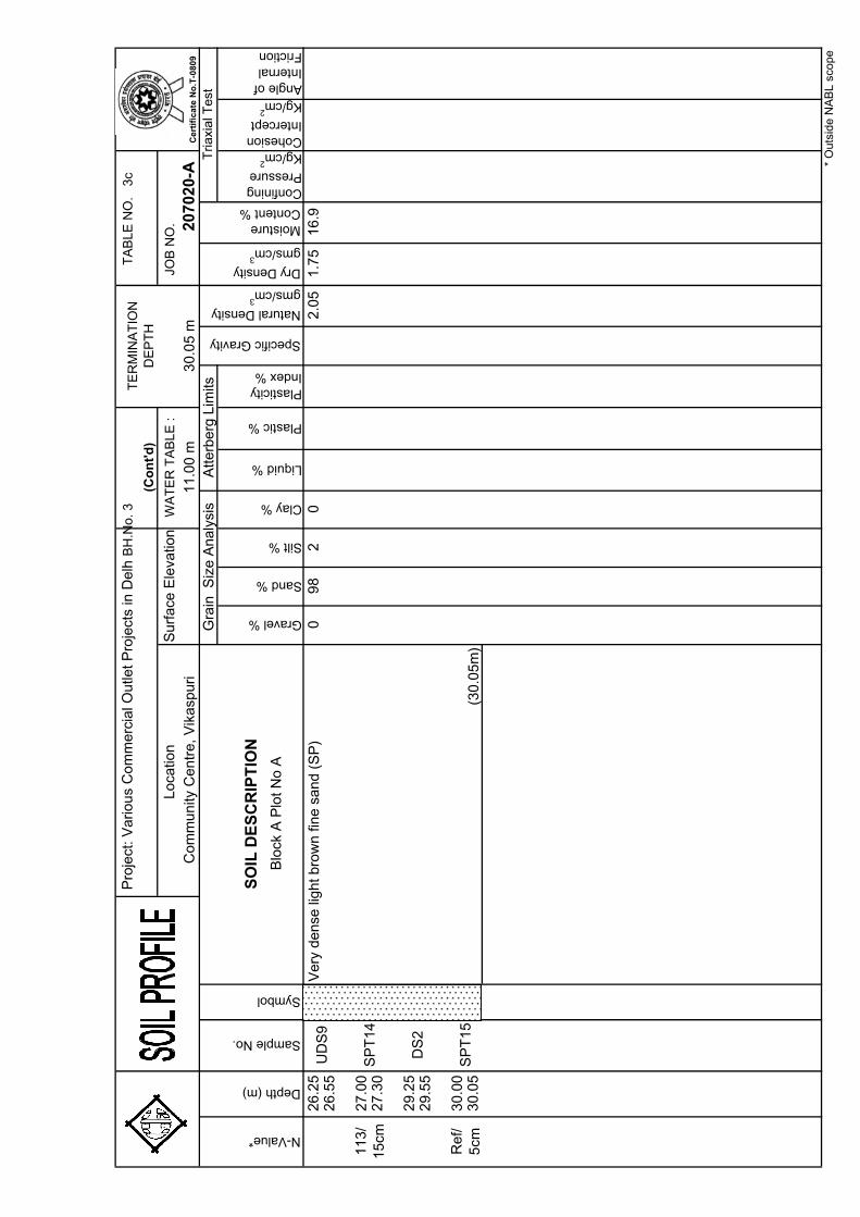
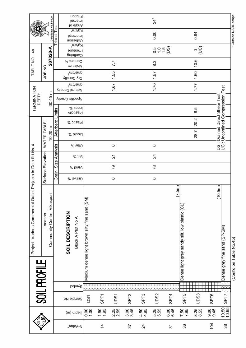
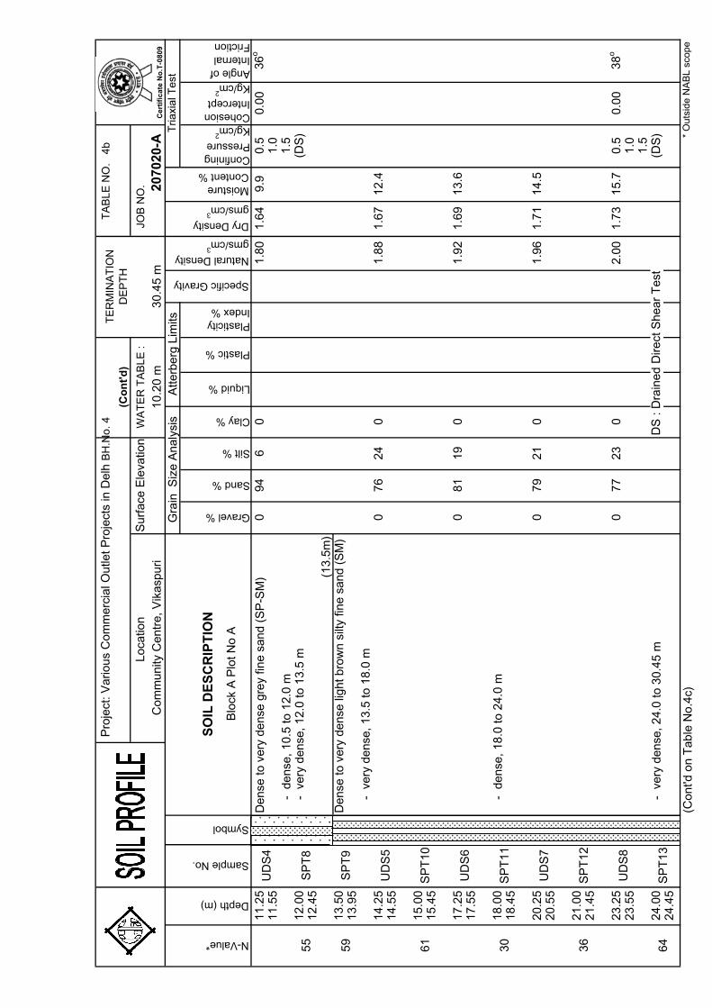
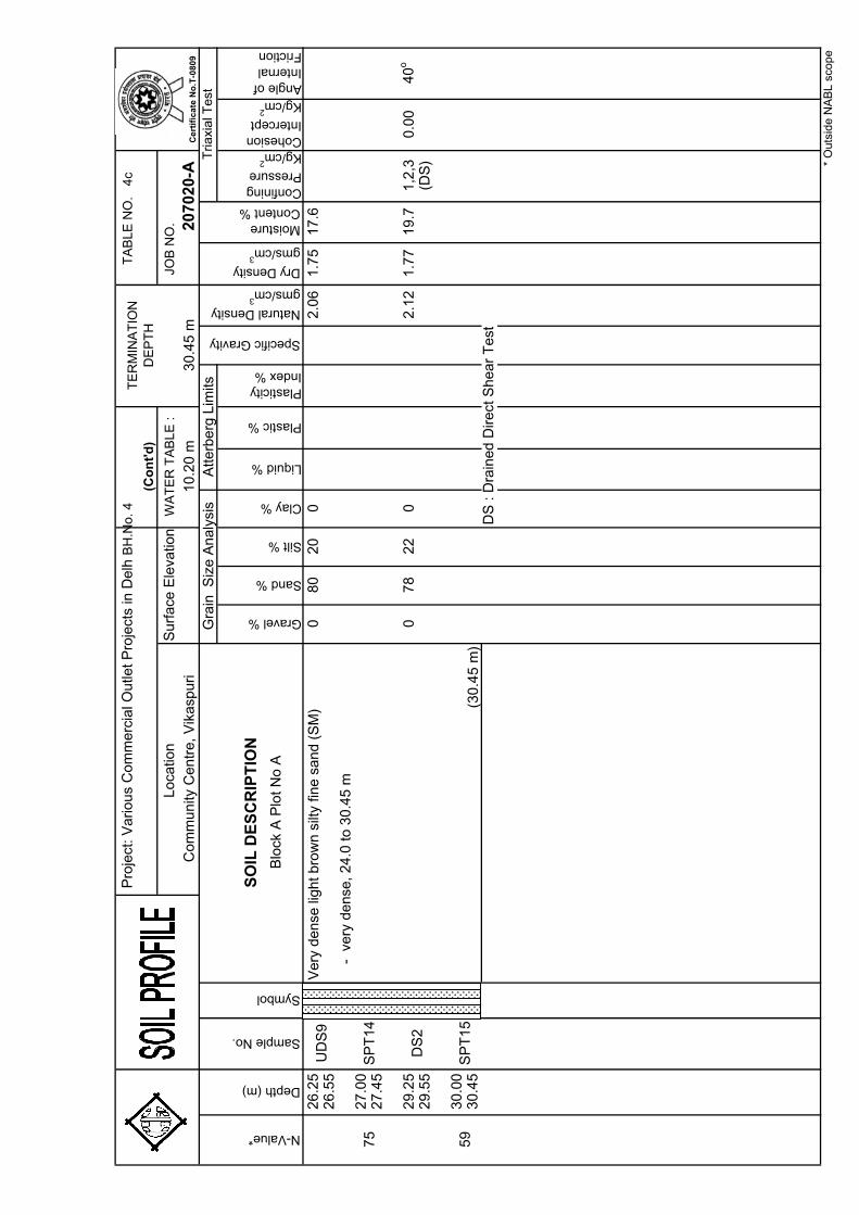
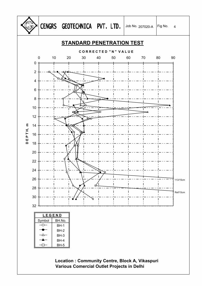
borehole occurred, 150 mm diameter casing was used to keep the borehole stable. The work was in general accordance with IS:1892-1979. Standard Penetration Tests (SPT) were conducted in the boreholes at 1.5 m depth intervals upto 15 m depth and 3.0 m depth intervals below by connecting a split spoon sampler to ‘A’ rods and driving it by 45 cm using a 63.5 kg hammer falling freely from a height of 75 cm. The tests were conducted in accordance with IS:2131-1981.
The number of blows for each 15 cm of penetration of the split spoon sampler was recorded. The blows required to penetrate the initial 15 cm of the split spoon for seating the sampler is ignored due to the possible presence of loose materials or cuttings from the drilling operation. The cumulative number of blows required to penetrate the balance 30 cm of the 45 cm sampling interval is termed the SPT value or the ‘N’ value.
The ‘N’ values are presented on the soil profile for each borehole. Refusal to further boring penetration was considered when the ‘N’ values exceed 100 or when practical refusal to further penetration by shell and auger was encountered. Where the ‘N’ value exceeded 100, the penetration of the split spoon sampler (after the initial seating) is recorded together with the number of blows given on the sampler. Where the seating blow count exceeded 100, the ‘N’ value is recorded as “Ref” on the soil profiles. Disturbed samples were collected from the split spoon after conducting SPT. The samples were preserved in transparent polythene bags. Undisturbed samples were collected by attaching 75 mm diameter thin walled ‘Shelby’ tubes and driving the sampler using a 63.5 kg hammer in accordance with IS: 2132-1986. The tubes were sealed with wax at both ends. All samples were transported to our NABL accredited laboratory at Delhi for further examination and testing. 2.2 Dynamic Cone Penetration Test
The dynamic cone penetration tests were conducted using a
50 mm diameter cone in general accordance with IS:4968 Part-I. The
207020-A 3
CENGRS GEOTECHNICA PVT. LTD. Job No. Sheet No.
cone is attached to ‘A’ rods and driven by means of 63.5 kg hammer falling freely from a height of 75 cm. The number of blows required for each 30 cm penetration of the cone is recorded. In order to limit the friction between the rods and the soil, the rods are rotated after every 1 to 1.5 m of cone penetration. Results are presented as blows per 30 cm penetration versus depth on Fig. No. 2. 2.3 Groundwater
Groundwater level was measured in the boreholes 24 hours
after drilling and sampling was completed. The measured water levels are recorded on the individual soil profiles.
3.0 LABORATORY TESTS
The laboratory testing has been carried out in our NABL accredited laboratory. The quality procedures in our laboratory conform to ISO/IEC-17025-2005.
The laboratory testing programme was aimed at verifying the field classifications and developing parameters for engineering analysis. All testing was performed in accordance with the current applicable IS specifications. The following tests were conducted on selected soil and water samples recovered from the boreholes:
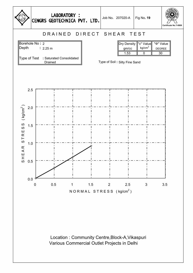
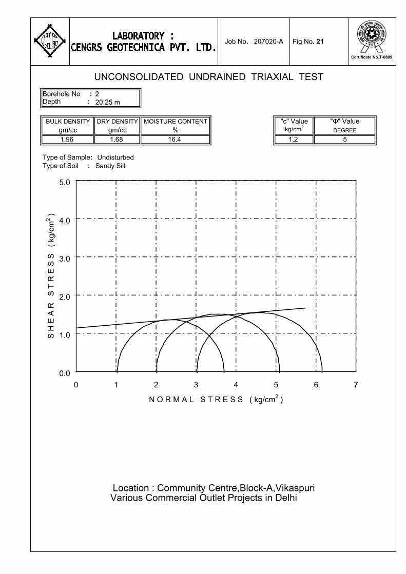
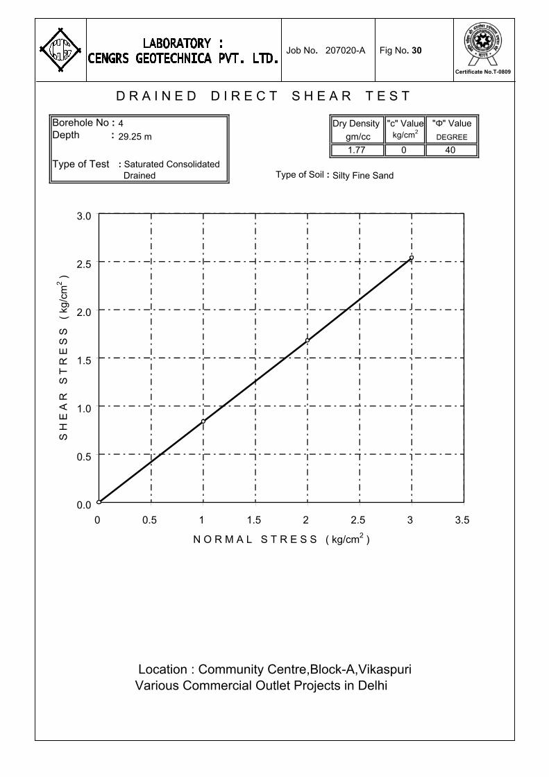
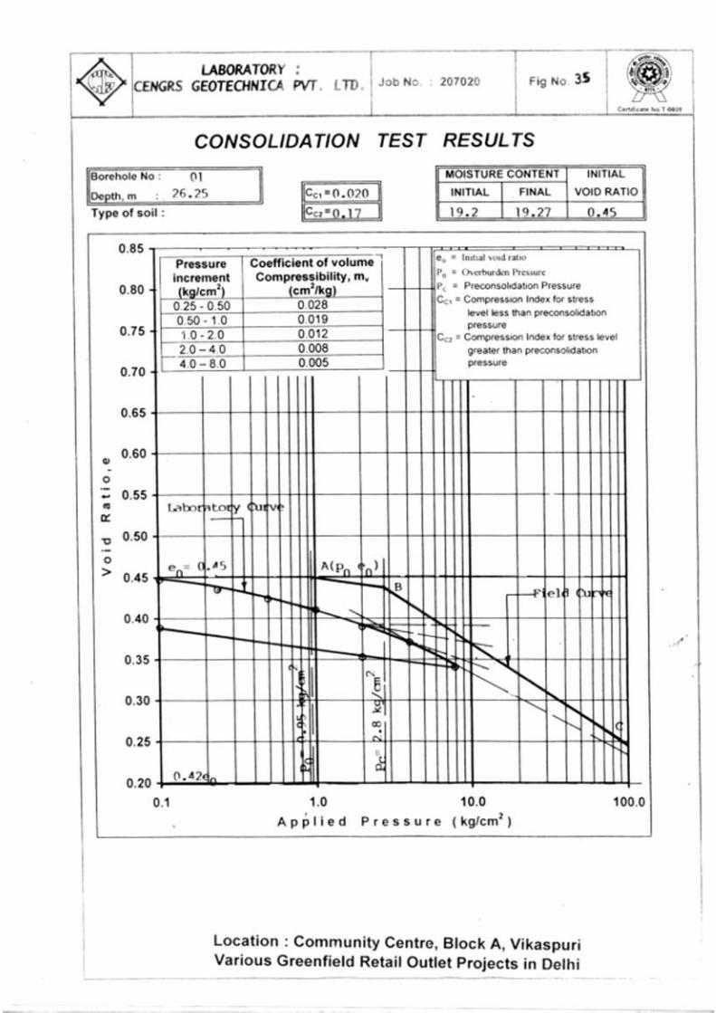
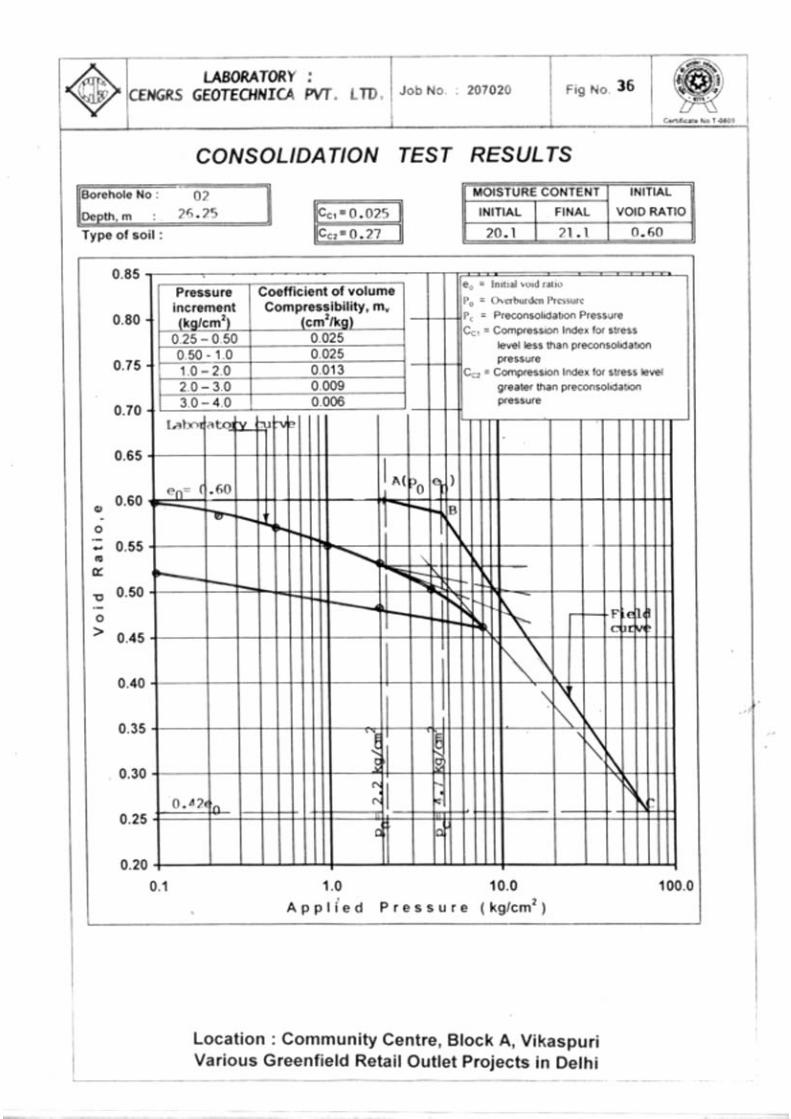
Laboratory Tests IS : Code Referred Bulk density & natural moisture content IS : 2720 (Part-2) -1973 Specific gravity IS : 2720 (Part-3) -1980 Grain size analysis IS : 2720 (Part-4) -1985 Liquid & plastic limit IS : 2720 (Part-5) -1985 Unconfined compression test IS : 2720 (Part-10) -1991 Unconsolidated undrained triaxial shear test IS : 2720 (Part-11) -1993 Consolidated drained direct shear test IS : 2720 (Part-13)-1986 Consolidation Test IS : 2720 (Part-15)-1986
pH value IS : 2720 (Part-26) -1987 Sulphate content IS : 2720 (Part-27) -1977 Chemical analysis*
of soil to determine Chloride content IS : 3025 (Part-32)-1993 pH value IS : 3025 (Part-11) -1996 Sulphate content IS : 3025 (Part-24) -1998 Chemical analysis*
for water to determine Chloride content IS : 3025 (Part-32)-1993 * outside NABL Scope
207020-A 4
CENGRS GEOTECHNICA PVT. LTD. Job No. Sheet No.
All test results are presented in the illustration section of this report. A note on our NABL accreditation together with the uncertainty in laboratory measurements is presented on Table 7.
4.0 GENERAL SITE CONDITIONS 4.1 Regional Geology
The soils at the project site belong to the “Indo Gangetic Alluvium”(1) and are river deposits of the Yamuna and its tributaries. The Pleistocene and Recent Deposits of the Indo-Gangetic Basin are composed of gravels, sands, silts and clays with remains of animal and plants. The older alluvium is rather dark coloured (locally called “Bhanger”) and is generally rich in concretions of nodules of impure calcium carbonate (Kankars). The kankars are of all shapes and sizes, varying from small sand sized grains to big lumps. The age of the “Bhanger” alluvium is Middle to Upper Pleistocene.
The newer alluvium (locally called “Khadar”) is light coloured and
poor in concretions. It contains lenticular beds of sand and gravel as well as peat beds. It is merged by insensible gradations into the Recent or deltaic alluvia and its age is Upper Pleistocene to Recent. 4.2 Site Stratigraphy
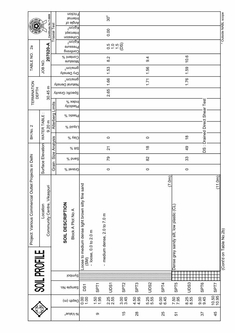
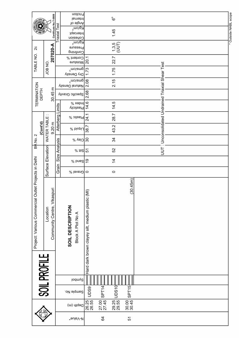
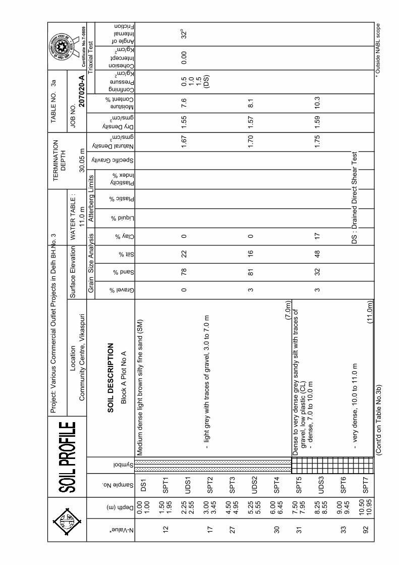
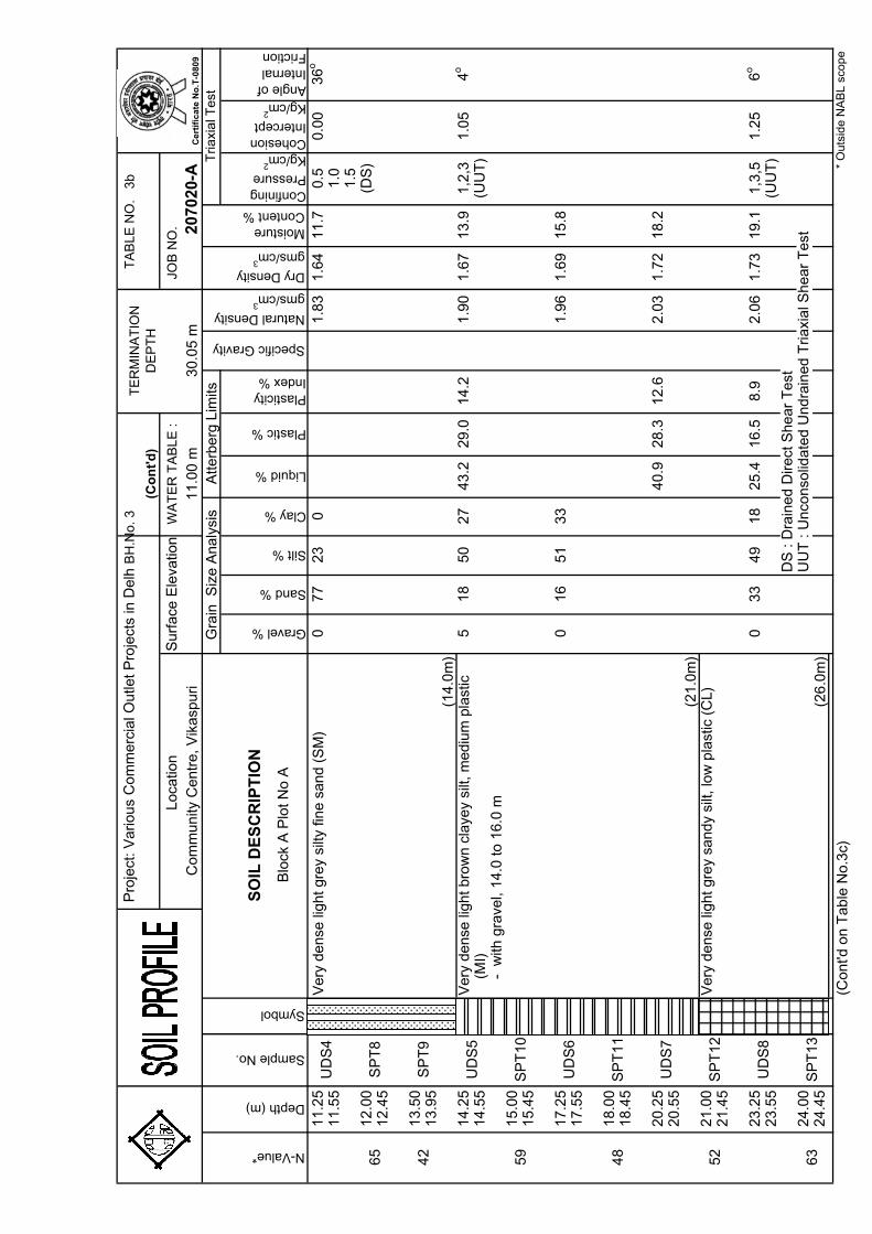
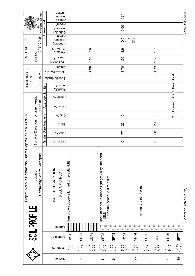
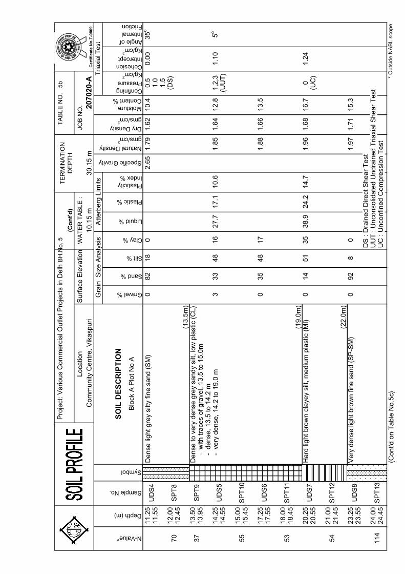
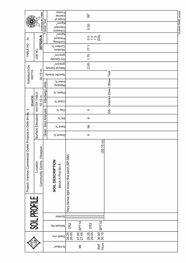
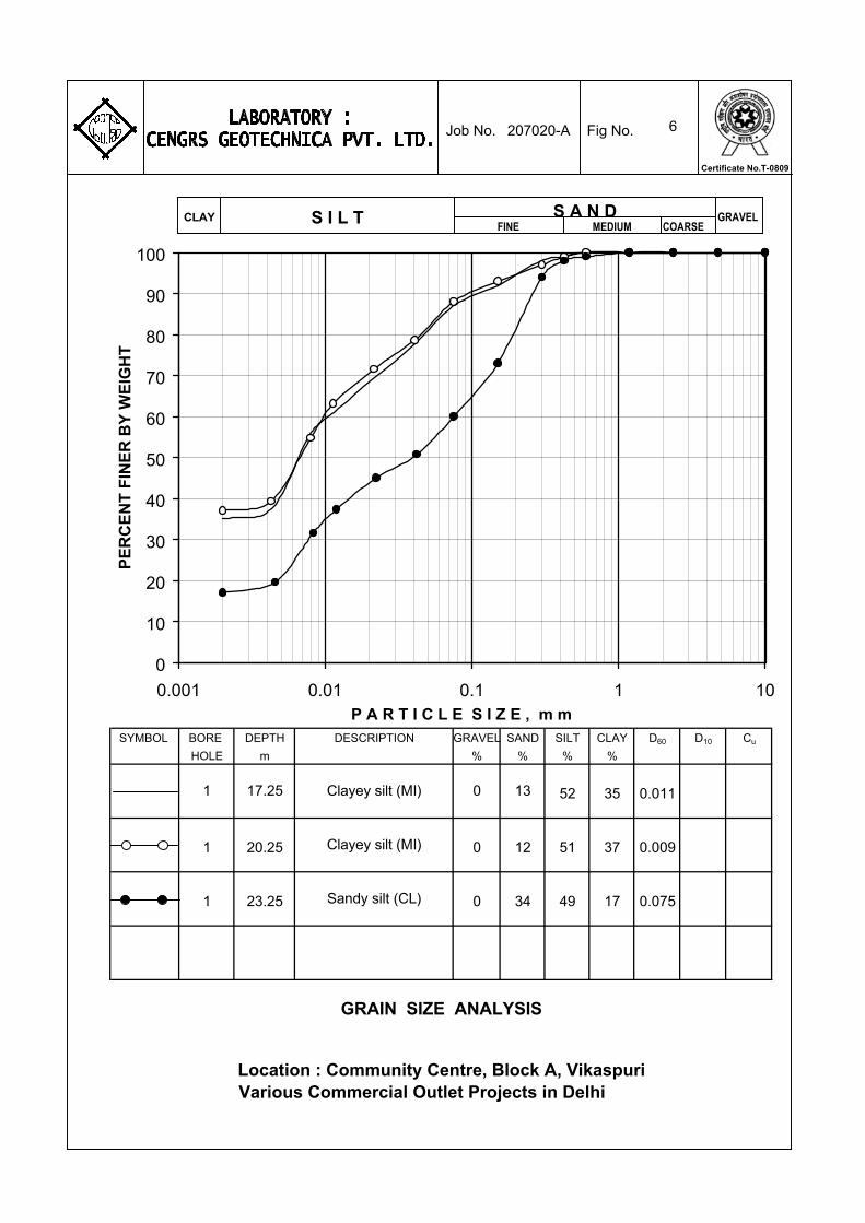
The soils at the site are alluvial in nature and consist of
alternating layers of silty sand / fine sand and sandy silt/clayey silt from the ground surface to the final explored depth of 30 m. Silty sand is met from the ground surface to about 7-8 m depth. This is underlain by sandy silt to about 11 m depth and silty sand to about 13-14 m depth. Sandy silty / clayey silt is then met to about 26-29 m depth. However, at BH-4, sand is met below 10.5 m depth that extends to the final explored depth of 30 m.
(1) Krishnan, M.S. (1986), “Geology of India & Burma”, CBS Publishers, New Delhi.
207020-A 5
CENGRS GEOTECHNICA PVT. LTD. Job No. Sheet No.
SPT N-values range from 9 to 15 to 3.0 m depth with some
higher values. However, at BH-5, SPT value of 5 is encountered at 1.5 m depth. Below this, SPT values generally range from 18 to 33 to about 10.0 m depth from 25 to 55 to about 20 to 21 m depth and from 28 to more than 100 to the final explored depth of 30.0 m.
DCPT values range from 8 to 15 to 2.0 m depth with some
higher values. Below this, DCPT values range from 16 to 34 to 7.0 m depth and from 35 to 50 to final test depth of 10.0 m.
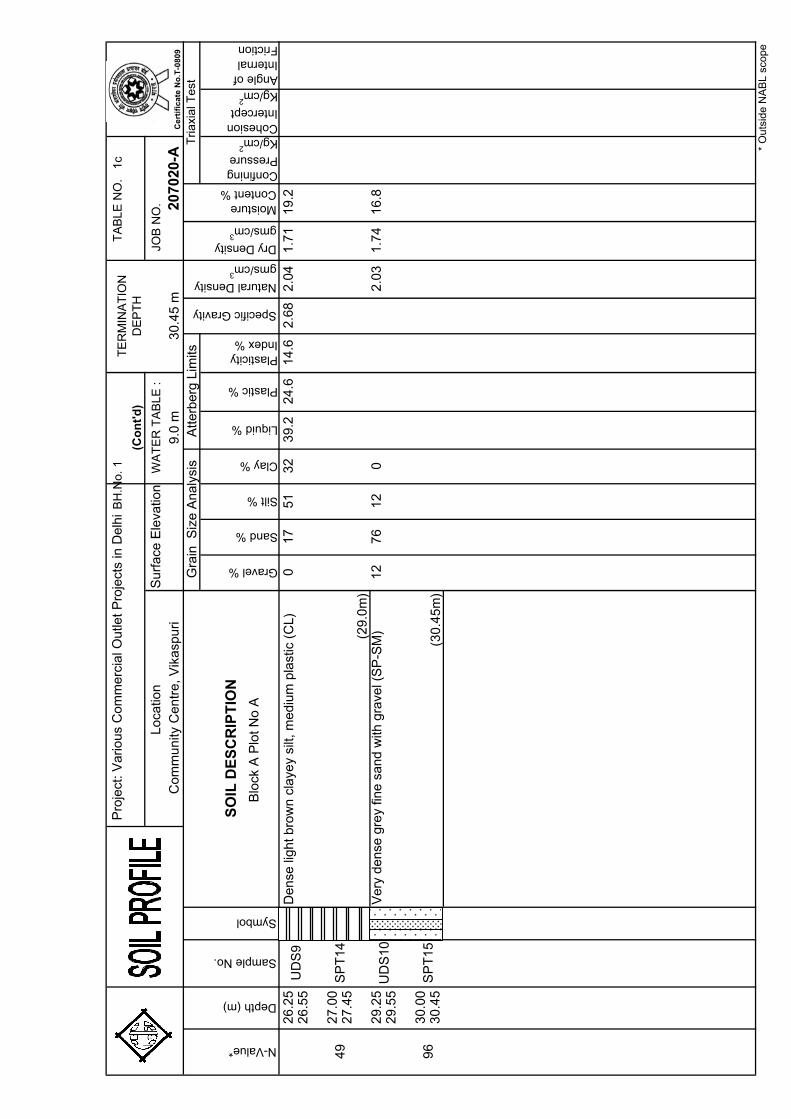
Detailed description of the materials encountered at the
borehole locations is presented on the individual soil profiles on Table 1 to 5. Engineering terms used for describing soils are explained on Table 6. Chemical test results are presented on Table 8. All laboratory data are presented graphically in the illustrations. A summary of the borehole profiles is presented on Fig. 3. Standard penetration test results are presented on Fig. 4.
4.3 Groundwater
Based on the measurements in the completed boreholes, groundwater was met between 9.0 to 11.0 m depth below existing ground level at the time of our field investigation (February, 2007). Fluctuations may occur in measured water levels due to seasonal variations in rainfall and surface evaporation rates.
5.0 FOUNDATION ANALYSIS AND RECOMMENDATIONS
5.1 General A suitable foundation for any structure should have an adequate factor of safety against exceeding the bearing capacity of the supporting soils. Also the vertical movements due to compression of the soils should be within tolerable limits for the structure. We consider that foundation designed in accordance with the recommendations given herein will satisfy these criteria.
5.2 Foundation Type and Depth
We understand that building will have a height of 26 m and shall have three basements. Individual isolated footings with interconnecting
207020-A 6
CENGRS GEOTECHNICA PVT. LTD. Job No. Sheet No.
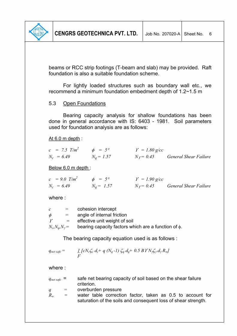
beams or RCC strip footings (T-beam and slab) may be provided. Raft foundation is also a suitable foundation scheme.
For lightly loaded structures such as boundary wall etc., we recommend a minimum foundation embedment depth of 1.2~1.5 m 5.3 Open Foundations
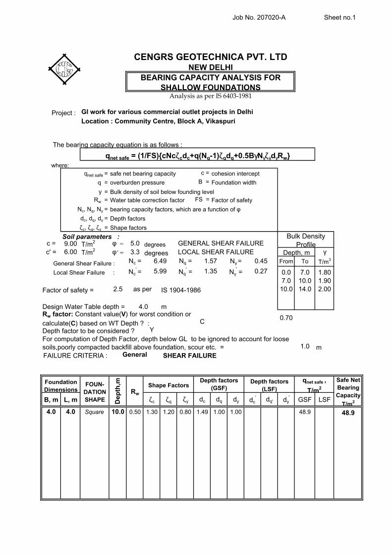
Bearing capacity analysis for shallow foundations has been done in general accordance with IS: 6403 - 1981. Soil parameters used for foundation analysis are as follows: At 6.0 m depth : c = 7.5 T/m2 φ = 5° ϒ = 1.80 g/cc Nc = 6.49 Nq = 1.57 Nϒ = 0.45 General Shear Failure Below 6.0 m depth : c = 9.0 T/m2 φ = 5° ϒ = 1.90 g/cc Nc = 6.49 Nq = 1.57 Nϒ = 0.45 General Shear Failure where : c = cohesion intercept φ = angle of internal friction ϒ = effective unit weight of soil Nc,Nq,Nγ = bearing capacity factors which are a function of φ. The bearing capacity equation used is as follows : qnet safe = 1 [cNcζc dc+ q (Nq -1) ζq dq+ 0.5 Bϒ Nγζγ dγ Rw] F where : qnet safe = safe net bearing capacity of soil based on the shear failure criterion. q = overburden pressure Rw = water table correction factor, taken as 0.5 to account for
saturation of the soils and consequent loss of shear strength.
207020-A 7
CENGRS GEOTECHNICA PVT. LTD. Job No. Sheet No.
F = factor of safety, taken as equal to 2.5 in accordance with IS: 1904. ζc, ζq, ζγ = Shape factors. For Strip footings, ζc = ζq = ζγ = 1. For Square footing ζc = 1.3, ζq = 1.2, ζγ = 0.6 dc, dq, dγ = depth factors For φ ≤ 10°, dc = 1+0.2 tan (45 + φ/2) D/B, dq = dγ = 1 For φ >10°, dq = dγ = 1 + 0.1 tan (45 + φ/2)D/B
Appropriate values have been substituted into the bearing
capacity equation given above to compute the safe net bearing capacity. The values have been checked to determine the settlement of the foundation under the safe bearing pressure. The allowable bearing pressure has been taken as the lower of the two values computed from the bearing capacity shear failure criterion as well as that computed from the tolerable settlement criterion. Settlement analysis has been performed based on the SPT values.
The following table presents our recommended values of net
The above values include a bearing capacity safety factor of 2.5.
Net bearing pressures for foundations at intermediate depths may be interpolated linearly between the values given above. The appropriate values of net bearing pressure may be selected as per the displacement computed from soil-structure interaction.
For lightly loaded facilities such as boundary wall etc., we
recommend a net allowable bearing pressure of 10 T/m2 at about 1.2~1.5 m depth.
207020-A 8
CENGRS GEOTECHNICA PVT. LTD. Job No. Sheet No.
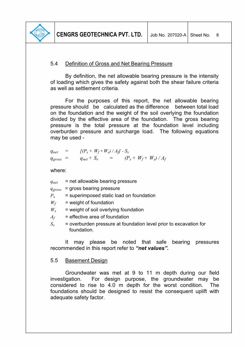
5.4 Definition of Gross and Net Bearing Pressure
By definition, the net allowable bearing pressure is the intensity
of loading which gives the safety against both the shear failure criteria as well as settlement criteria.
For the purposes of this report, the net allowable bearing
pressure should be calculated as the difference between total load on the foundation and the weight of the soil overlying the foundation divided by the effective area of the foundation. The gross bearing pressure is the total pressure at the foundation level including overburden pressure and surcharge load. The following equations may be used - qnet = [(Ps + Wf +Ws) / Af] - Sv qgross = qnet + Sv = (Ps + Wf + Ws) / Af where:
qnet = net allowable bearing pressure qgross = gross bearing pressure Ps = superimposed static load on foundation Wf = weight of foundation Ws = weight of soil overlying foundation Af = effective area of foundation Sv = overburden pressure at foundation level prior to excavation for foundation.
It may please be noted that safe bearing pressures
recommended in this report refer to “net values”. 5.5 Basement Design Groundwater was met at 9 to 11 m depth during our field investigation. For design purpose, the groundwater may be considered to rise to 4.0 m depth for the worst condition. The foundations should be designed to resist the consequent uplift with adequate safety factor.
207020-A 9
CENGRS GEOTECHNICA PVT. LTD. Job No. Sheet No.
The basement should be designed to resist lateral earth pressure due to backfill and saturation of soils due to rains etc. For design purpose, we recommend the following values of co-efficient of earth pressures for the active, passive and at rest condition.
Depth, m From To ka kp ko 0.0 5.0 0.39 2.56 0.56 5.0 10.0 0.36 2.78 0.53 10.0 15.0 0.33 3.00 0.50
where: ka = Co-efficient of active earth pressure kp = Co-efficient of passive earth pressure ko = Co-efficient of earth pressure at rest A suitable safety factor should be applied on the passive earth pressures in the design of the wall. 5.6 Liquefaction Potential
As per IS:1893-2002, liquefaction is likely in fine sand (SP) below water table for SPT values less than 15. In general SPT values in the sand layer exceeds 15. Groundwater was met at 9.0 to 11.0 m depth. The soils classify as sandy silt and silty sand.
On review of all the soil parameters like in-situ density, dry
density, SPT values, we are of the opinion that liquefaction is not likely to take place.
According to Fig.1 of IS:1893 (Part-1)-2002 showing seismic
zones, the proposed site falls under Zone-IV. The design for seismic forces should be done considering the project in Zone-IV.
6.0 FOUNDATION CONSTRUCTION CONSIDERATION
6.1 Excavation Temporary open cut excavation to about 3.0 m depth may be cut
using side slopes of 1 vertical on 0.2 to 0.4 horizontal. Below this, the
207020-A 10
CENGRS GEOTECHNICA PVT. LTD. Job No. Sheet No.
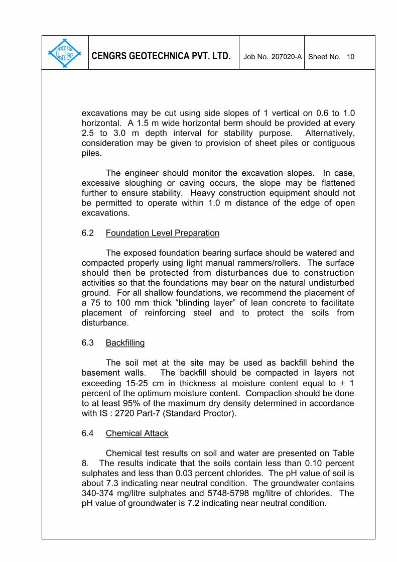
excavations may be cut using side slopes of 1 vertical on 0.6 to 1.0 horizontal. A 1.5 m wide horizontal berm should be provided at every 2.5 to 3.0 m depth interval for stability purpose. Alternatively, consideration may be given to provision of sheet piles or contiguous piles.
The engineer should monitor the excavation slopes. In case,
excessive sloughing or caving occurs, the slope may be flattened further to ensure stability. Heavy construction equipment should not be permitted to operate within 1.0 m distance of the edge of open excavations. 6.2 Foundation Level Preparation
The exposed foundation bearing surface should be watered and compacted properly using light manual rammers/rollers. The surface should then be protected from disturbances due to construction activities so that the foundations may bear on the natural undisturbed ground. For all shallow foundations, we recommend the placement of a 75 to 100 mm thick “blinding layer” of lean concrete to facilitate placement of reinforcing steel and to protect the soils from disturbance.
6.3 Backfilling
The soil met at the site may be used as backfill behind the basement walls. The backfill should be compacted in layers not exceeding 15-25 cm in thickness at moisture content equal to ± 1 percent of the optimum moisture content. Compaction should be done to at least 95% of the maximum dry density determined in accordance with IS : 2720 Part-7 (Standard Proctor). 6.4 Chemical Attack
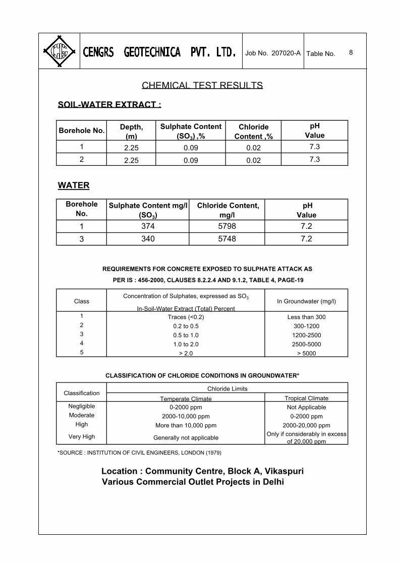
Chemical test results on soil and water are presented on Table
8. The results indicate that the soils contain less than 0.10 percent sulphates and less than 0.03 percent chlorides. The pH value of soil is about 7.3 indicating near neutral condition. The groundwater contains 340-374 mg/litre sulphates and 5748-5798 mg/litre of chlorides. The pH value of groundwater is 7.2 indicating near neutral condition.
207020-A 11
CENGRS GEOTECHNICA PVT. LTD. Job No. Sheet No.
IS:456-2000 classifies the sulphate content of the soils into three classes. For Class-II, the concentration of sulphates in soils is given as 0.2 to 0.5 percent in soils and 300 to 1200 mg/litre in groundwater. Groundwater is at about 9.0 to 11.0 m, and there is potential for rise of water table. Comparing the test results with these specified limits, the sulphate content of soils is less than the specified limit, and the sulphate content of groundwater is marginally above this limit. The strata at the site is therefore considered in Class-II which indicates moderately aggressive condition on the basis of sulphate attack. Bartholomew(2) states that for tropical climate conditions, a chloride content exceeding 2000 ppm indicates a high potential for corrosion. Since chlorides in the groundwater exceeds this limit, in our opinion, the strata at site is highly aggressive. Whereas sulphates attack concrete and causes its deterioration and spalling, chlorides will accelerate the corrosion of steel members and reinforcement steel embedded in concrete. We recommend the following measures to protect the foundations from corrosion in aggressive environment.
(1) For foundation concrete, the minimum cement content should be
at least 330 kg/cu.m. Portland Pozzolona cement or slag cement may be used for concrete.
(2) It should be ensured that the coarse aggregates used for
concrete complies with the requirements of durability and soundness as given in IS:383.
(3) Water cement ratio in foundation concrete should not exceed
0.50. If required, admixtures may be used to improve workability.
(2) Bartholomew, R.F. (1979), “The Protection of Concrete Piles in Aggressive Ground Conditions”, Recent developments in design and construction of piles, Institution of Civil Engineers, London.
207020-A 12
CENGRS GEOTECHNICA PVT. LTD. Job No. Sheet No.
(4) A clear concrete cover over the reinforcement steel of at least
50 mm should be provided for all foundations. (5) Foundation concrete should be densified adequately using a
vibrator so as to form a dense impervious mass. Honeycombing of concrete or other defects can accelerate the corrosion process. Therefore, adequate quality control should be exercised on site to ensure good quality concrete of low permeability.
(6) The mixing water and curing water for foundations concrete
should be tested and suitable water conforming to IS:456 should be used for concreting and curing.
(7) Corrosion resistant steel (CRS) may be provided for
reinforcement steel. Alternatively, epoxy coating may be provided on the tor steel reinforcement.
6.5 Variability in Subsurface Conditions
Subsurface conditions encountered during construction may vary somewhat from the conditions encountered during the site investigation. In case significant variations are encountered during construction, we request to be notified so that our engineers may review the recommendations in this report in light of these variations.
7.0 SUMMARY OF PRINCIPAL FINDINGS AND RECOMMENDATIONS
M/s. Cengrs Geotechnica Private Limited conducted a
geotechnical investigation for Commercial Outlet Project at Community Centre, Block-A, Vikaspuri in New Delhi. The scope of work included five boreholes to 30 m depth and five dynamic cone penetration tests to 10 m depth.
The soils at the site are alluvial in nature and consist of
alternating layers of silty sand / fine sand and sandy silt / clayey silt from the ground surface to final explored depth of 30 m. Groundwater was met between 9.0 and 11.0 m depth below existing ground level at the time of our field investigation (February, 2007).
207020-A 13
CENGRS GEOTECHNICA PVT. LTD. Job No. Sheet No.
Isolated foundations with a connecting beams, RCC strip
footings (T-beam and slab) and raft foundation are suitable foundation schemes. Net bearing pressures for different settlements are given in Section 5.3 of this report. The appropriate net bearing pressure may be selected for the desired settlement as computed from soil-structure interaction.
8.0 CLOSURE
We appreciate the opportunity to perform this investigation for you and have pleasure in submitting this report. Please contact us when we can be of further service to you.
for CENGRS GEOTECHNICA PRIVATE LIMITED
(RAVI SUNDARAM) (SANJAY GUPTA) DIRECTOR MANAGING DIRECTOR
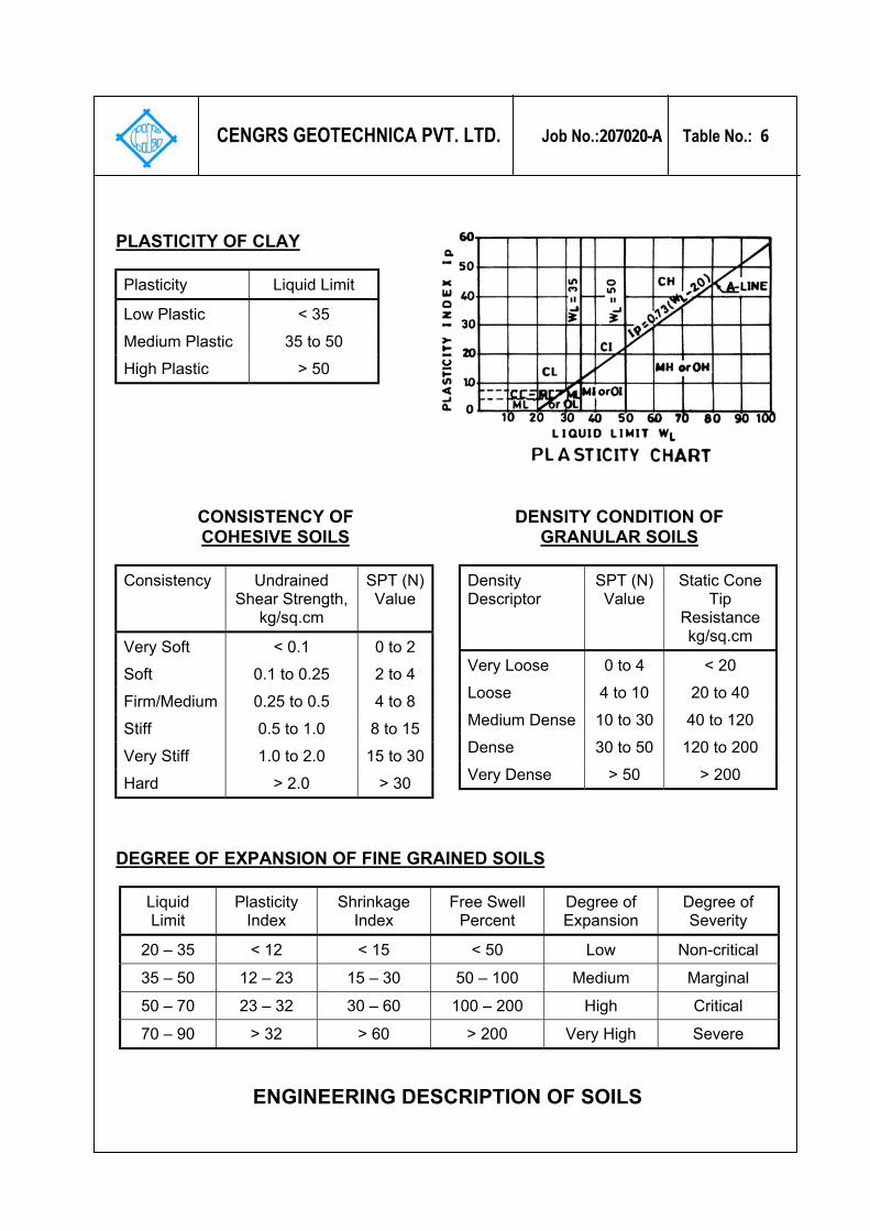
Low Plastic < 35 Medium Plastic 35 to 50 High Plastic > 50
CONSISTENCY OF COHESIVE SOILS
Consistency Undrained Shear Strength,
kg/sq.cm
SPT (N) Value
Very Soft < 0.1 0 to 2 Soft 0.1 to 0.25 2 to 4 Firm/Medium 0.25 to 0.5 4 to 8 Stiff 0.5 to 1.0 8 to 15 Very Stiff 1.0 to 2.0 15 to 30 Hard > 2.0 > 30
DENSITY CONDITION OF GRANULAR SOILS
Density Descriptor
SPT (N) Value
Static Cone Tip
Resistance kg/sq.cm
Very Loose 0 to 4 < 20 Loose 4 to 10 20 to 40 Medium Dense 10 to 30 40 to 120 Dense 30 to 50 120 to 200 Very Dense > 50 > 200
DEGREE OF EXPANSION OF FINE GRAINED SOILS
Liquid Limit
Plasticity Index
Shrinkage Index
Free Swell Percent
Degree of Expansion
Degree of Severity
20 – 35 < 12 < 15 < 50 Low Non-critical
35 – 50 12 – 23 15 – 30 50 – 100 Medium Marginal
50 – 70 23 – 32 30 – 60 100 – 200 High Critical
70 – 90 > 32 > 60 > 200 Very High Severe
ENGINEERING DESCRIPTION OF SOILS
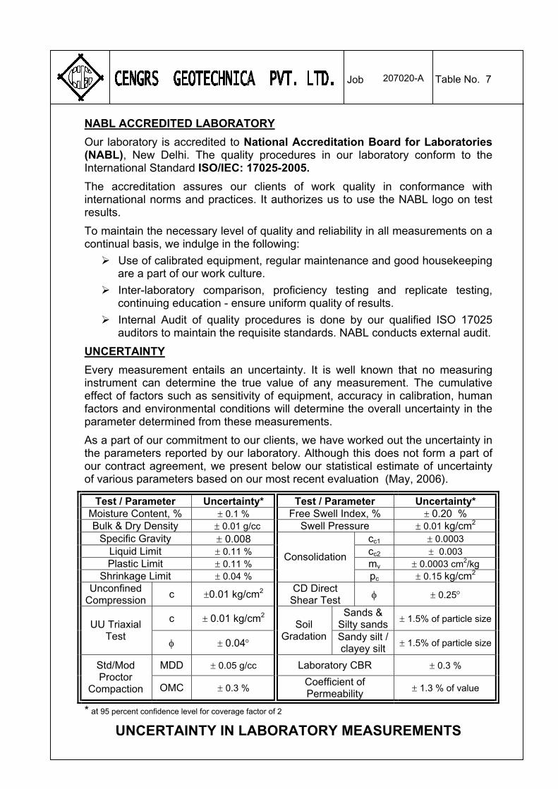
NABL ACCREDITED LABORATORY
207020-A Table No. 7 Job
Our laboratory is accredited to National Accreditation Board for Laboratories (NABL), New Delhi. The quality procedures in our laboratory conform to the International Standard ISO/IEC: 17025-2005.
The accreditation assures our clients of work quality in conformance with international norms and practices. It authorizes us to use the NABL logo on test results.
To maintain the necessary level of quality and reliability in all measurements on a continual basis, we indulge in the following:
Use of calibrated equipment, regular maintenance and good housekeeping are a part of our work culture.
Inter-laboratory comparison, proficiency testing and replicate testing, continuing education - ensure uniform quality of results.
Internal Audit of quality procedures is done by our qualified ISO 17025 auditors to maintain the requisite standards. NABL conducts external audit.
UNCERTAINTY
Every measurement entails an uncertainty. It is well known that no measuring instrument can determine the true value of any measurement. The cumulative effect of factors such as sensitivity of equipment, accuracy in calibration, human factors and environmental conditions will determine the overall uncertainty in the parameter determined from these measurements.
As a part of our commitment to our clients, we have worked out the uncertainty in the parameters reported by our laboratory. Although this does not form a part of our contract agreement, we present below our statistical estimate of uncertainty of various parameters based on our most recent evaluation (May, 2006).


![v. Nanjing Auchan Hypermarket Co., Ltd. Jiangning Store, A ... · Hypermarket Jiangning Store’s defense, claiming that SUN Yinshan was not a consumer [because he purposefully] “bought](https://static.documents.pub/doc/80x56/601f00f7a9975b28614dbc64/v-nanjing-auchan-hypermarket-co-ltd-jiangning-store-a-hypermarket-jiangning.jpg)