Christopher L. Holloway, Senior Member, IEEE, M. Sabrina Sarto, Senior Member, IEEE, andMartin Johansson, Member, IEEE
Abstract—The purpose of this paper is to investigate the useof equivalent-layer models for the analysis of carbon-fiber com-posite materials. In this paper, we present three different modelsfor the electromagnetic characterization (effective material prop-erties) of fiber composites that are commonly used in aircraft andEMC/EMI shielding materials. These three models represent vari-ous orders (or levels) of detail in the fiber composite structure and,hence, capture various physical aspects of the composite. Thesemodels can be used to efficiently calculate the reflection and trans-mission coefficients, as well as the shielding effectiveness, of thesefiber composites. We compare results of the reflection coefficientand shielding effectiveness obtained from these effective-propertymodels to results obtained from a full numerical solution based onthe finite-element (FE) method of the actual periodic fiber com-posite. We show that, as expected, as more of the geometric detailof the fiber composite is captured with the different models, theupper frequency limit of validity increases.
Index Terms—Carbon fiber composites, effective material prop-erties, effective media, homogenization, shielding effectiveness,shielding materials.
I. INTRODUCTION
ADVANCED composite materials (ACM) have madetremendous inroads into the spacecraft and aircraft indus-
tries [1]–[13] as replacements for metals. The composites offerlow-weight construction and electromagnetic shielding materi-als. In recent years, composites have begun to spill over intoother applications such as casings and housings used in elec-tronics, computer, and business equipment; in the naval and in-dustrial environments; and for transportation and construction(including infrastructure applications such as bridges, pipeline,and buildings) [8], [9]. Composite materials are typically com-posed of a binding matrix of various different materials (e.g.,metallic, polymeric, ceramic, etc.), reinforced by inclusions hav-ing different shapes (long and short fibers, whiskers, flakes,filaments). Advanced composite materials are relatively newmaterials that derive their origin from the fiberglass-reinforcedplastics industry. They are realized by a resin matrix reinforcedby high strength fibers, such as graphite, boron, glass, carbon,or aramid [5].
Manuscript received October 29, 2003; revised May 17, 2005. This work wassupported in part by the U.S. Department of Commerce.
C. L. Holloway is with the National Institute of Standards and Technology,Electromagnetics Division, U.S. Department of Commerce, Boulder Laborato-ries, Boulder, CO 80305 USA (e-mail: [email protected]).
M. S. Sarto is with the Department of Electrical Engineering, University ofRoma “La Sapienza,” 00184 Rome, Italy.
M. Johansson is with the Antenna Research Center, Ericsson AB, SE-41756Gothenburg, Sweden.
Digital Object Identifier 10.1109/TEMC.2005.854101
Fig. 1. Multiple-panel composite structure. The subscript “i” indicates thelayer number, and “m” is the total number of layers.
Composite panels are manufactured by pressing and bindingtogether several matrix-reinforced laminates that have differentfiber orientations. Each ACM layer is realized by unidirectionalreinforcement or by woven fabric. Due to the nonhomogeneousnature of composites, the surface and volume resistivity of acarbon-fiber composite panel can be defined only in an averagesense. Both the surface and volume resistivity and the shieldingeffectiveness of composite structures are strongly affected bythe fiber-composition fraction or percentage.
The main advantages of these materials with respect to met-als are the superior mechanical and chemical properties suchas lower weight, higher stiffness and strength, lower corrosion,lower tooling costs, and greater ease of fabrication. Despitethese benefits, composite materials are not as electrically con-ductive as traditional metallic ones. For example, a carbon-fiber-reinforced composite (CFRC) has an electrical conductivity thatis nearly 1000 times lower than that of most metals [6], [7].
The electrical performance of ACMs depends strongly on thecharacteristics of fabrication. One type of fiber-reinforced com-posite is made from loose fibers that are mixed with resins anda hardening agent to form a solid composite; see Figs. 1 and 2.Another type is made from unidirectional fibers prepackagedwith resins as tape or woven fabric. The tape or fabric is placedin layers to form the finished composite material. Electrical con-ductivity and mechanical strength are higher in the direction offiber reinforcement; see Fig. 1.
Due to the fact that ACMs are being used more frequentlyfor the packaging and shielding of electrical and electronic
834 IEEE TRANSACTIONS ON ELECTROMAGNETIC COMPATIBILITY, VOL. 47, NO. 4, NOVEMBER 2005
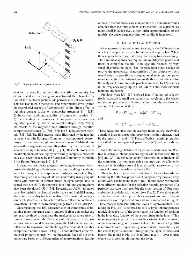
Fig. 2. Single-panel fiber composite structure.
devices for complex systems, the scientific community hasdemonstrated an increasing interest toward the characteriza-tion of the electromagnetic (EM) performances of composites.This has lead to both theoretical and experimental investigationon several EM aspects of composites: 1) the direct effect oflightning current stroke on composite structures [14]–[21];2) the current-handling capability of composite materials [7];3) the shielding performances of composite structures hav-ing either planar, cylindrical, or complex shapes [22]–[29]; 4)the effects of the magnetic field diffusion through metallic-composite enclosures [9], [30]–[37]; and 5) measurement meth-ods [38]–[52]. The EM interest is also illustrated by the fact thatin recent years the European Community has supported researchprojects to analyze the lightning interaction and EM-field haz-ards with new-generation aircraft realized by the inclusion ofadvanced composite materials [10], [11]. Research projects forthe development of new highly performing composite materialshave also been financed by the European Community within theBrite-Euram Programme [12], [13].
In fact, new composite materials are being developed to im-prove the shielding effectiveness, current-handling capability,and electromagnetic absorption of existing composites. Highelectromagnetic shielding ACMs are achieved by using graphitefibers with bromine or similar mixed halogen compounds, orcoated with nickel. To this purpose, thin films and coatings havealso been developed [53], [54]. Recently, an ACM laminatedpanel having high mechanical performance and high EM energyabsorption capability has been realized. This material, having asandwich structure, is characterized by a reflection coefficientlower than−17 dB in the frequency range from 7 to 18 GHz [55].
Understanding the EM characteristics of composites is be-coming more important and is required if fiber composites aregoing to continue to penetrate the market as an alternative tostandard metal materials. The intent of this paper is to discussvarious efficient models for analyzing the EM interaction (i.e.,reflection, transmission, and shielding effectiveness) of the fibercomposite material shown in Fig. 1. Three different effective-material-property models will be presented. Each of the threemodels are based on different orders of approximations. Results
of these different models are compared to full numerical resultsobtained from the finite-element (FE) method . As expected, asmore detail is added (i.e., a high-order approximation) to themodels, the upper frequency limit of validity is increased.
II. EQUIVALENT-LAYER MODELS
One approach that can be used to analyze the EM interactionof a fiber composite is to use full numerical approaches. Whilethese approaches are accurate, they can be very time-consuming.The numerical approaches require thin multilayered panels andfibers of composite material to be spatially resolved by verysmall discretization steps. The discretization steps needed toresolve the geometrical characteristics of the composite fiberswould result in prohibitive computational time and computermemory needs. Even subgridding methods are not efficient forthe analysis of thin composite panels illuminated by EM sourcesin the frequency range up to a 100 MHz. Thus, more efficientmethods are needed.
Previous work [56]–[59] showed that, if the period of a pe-riodic structure is small compared to a wavelength, the wavessee the composite as an effective medium, and the zeroth-orderaverage fields are related by
∇× (Eo)avg = −jω[µh ] · (Ho)avg
and
∇× (Ho)avg = jω[εh ] · (Eo)avg.
These equations state that the average fields satisfy Maxwell’sequations in an anisotropic homogeneous medium characterizedby the tensors [εh ] and [µh ]. These effective material propertiesare called the homogenized permittivity [εh ] and permeability[µh ].
Since the average fields treat the periodic medium as an effec-tive anisotropic inhomogeneous region with tensor permittivity[εh ] and [µh ], the reflection and/or transmission coefficients ofthe composite (or homogenized) structures can be efficientlyobtained with either classical layered media approaches or byclassical transmission-line methods [56].
There has been a great deal of attention in the past towards de-termining the effective properties of composite regions; a surveyof this work can be found in [60]–[62]. In this paper, we presentthree different models for the effective material properties of aperiodic structure that resemble the cross-section of fiber rodsembedded in a dielectric medium (see Fig. 2). These three mod-els are based on reducing the fiber composite to three differentequivalent-layer representations and are summarized in Fig. 3.These models represent different levels of approximation. Themodel in Fig. 3(a) is referred to as a 3-layer inhomogeneousmodel, since the εeff of the center layer is a function of positionin the layer (i.e., function of the y-coordinate in the layer). Thisinhomogeneity in y is attributed to the variation in the geometryof the structure in y, as discussed below. The model in Fig. 3(b)is referred to as a 3-layer homogeneous model, since the εeff ofthe center layer is constant throughout the layer, as discussedbelow. The model in Fig. 3(c) is referred to as a 1-layer model,where εeff is constant throughout the layer.
HOLLOWAY et al.: ANALYZING CARBON-FIBER COMPOSITE MATERIALS WITH EQUIVALENT-LAYER MODELS 835
Fig. 3. Single-panel fiber composite models: (a) 3-layer inhomogeneousmodel, where εeff = f (y) in layer 2, (b) 3-layer homogeneous model, whereεeff is constant throughout layer 2, and (c) 1-layer model.
A. 3-Layer Inhomogeneous Model
In this model the fiber composite panel shown in Fig. 2 isrepresented by the 3-layer model shown in Fig. 3(a). As thewave propagates into the fiber composite panel shown in Fig. 2,it experiences three separate regions. The wave first enters thepanel and sees a homogeneous layer [region 1 in Fig. 3(a)].This layer has constant material properties which correspondto that of the matrix, or resin, that surrounds the fiber. Thelayer has a thickness t which corresponds to the distance fromthe edge of the panel to the edge of the fiber, and ε = εm . As awave propagates into the second region [the region defined fromone edge of the fiber to the other edge, region 2 in Fig. 3(a)],
Fig. 4. Typical cross section of the fiber matrix.
Fig. 5. Periodic laminated medium, where s = 2√
Dy ′ − y ′2, y ′ is the dis-tance into region 2, and D is the diameter of the fibers.
the wave sees an increasing cross-section of the fiber until thecenter of the fiber is reached. At that point, the wave sees adecreasing cross-section of the fiber. An illustration of this isdepicted in Fig. 4. This suggests an inhomogeneous layer, andmaterial properties of such a layer are given below. The thicknessof the layer is D (the diameter of the fibers). The wave finallyenters a homogeneous layer [region 3 in Fig. 3(a)]. This layeris identical to layer 1 (i.e., constant material properties ε = εm
and thickness t).At any given cross-section in the inhomogeneous layer
(region 2), the material properties are approximated by theeffective material properties of the periodic laminated mediumshown in Fig. 5. It is known [62]–[67] that this type of mediumbehaves like a uniaxially anisotropic but homogeneous materialwith the following (possibly complex) tensor permittivity andpermeability
[ε] =
εx 0 0
0 εy 00 0 εz
(1)
836 IEEE TRANSACTIONS ON ELECTROMAGNETIC COMPATIBILITY, VOL. 47, NO. 4, NOVEMBER 2005
Fig. 6. Coordinate transformation for single-panel fiber composite structure.
[µ] =
µx 0 0
0 µy 00 0 µz
(2)
where
ε−1x = (1 − g)ε−1
a + gε−1b
µ−1x = (1 − g)µ−1
a + gµ−1b
εy = εz = (1 − g)εa + gεb
µy = µz = (1 − g)µa + gµb (3)
εa , µa , εb , and µb are defined in Fig. 5, and g is the relativevolume of space occupied by the material with εb or µb .
The effective material properties of the inhomogeneous layer(region 2) can be approximated by the expressions given in (3)by allowing εa to represent the material surrounding the rods(or εm ), and allowing εb to represent the permittivity of the rods(or εf ), where g is the relative volume of space occupied bythe rods at a given distance y′ as defined in Fig. 4. Unlike thelaminated medium, g for region 2 in Fig. 3(a) is a function ofthe distance (y′) measured from the surface to back edge of therods and is given by
g =2√
Dy′ − y′2
p(4)
where y′ ranges from 0 to D (see Fig. 4). This model capturesthe most detail of the fiber panel of the three models presentedin this paper. Hence, this model is more accurate than the othermodels for higher frequencies.
In some situations, the principal coordinates of the fiber maynot correspond to the coordinates of the electromagnetic fieldsincident on the composite structure, as shown in Fig. 6. In thisfigure, the ψ−ξ axis corresponds to the x−z axis rotated by anangle α. When this occurs, the following coordinate transform
can be used:
Ez
Hx
Ex
Hz
= [R]
Eψ
Hξ
Eξ
Hψ
(5)
where [R] is a 4× 4 transformation matrix, given by
[R] =
cos(α) 0 sin(α) 00 cos(α) 0 − sin(α)
− sin(α) 0 cos(α) 00 sin(α) 0 cos(α)
. (6)
B. 3-Layer Homogeneous Model
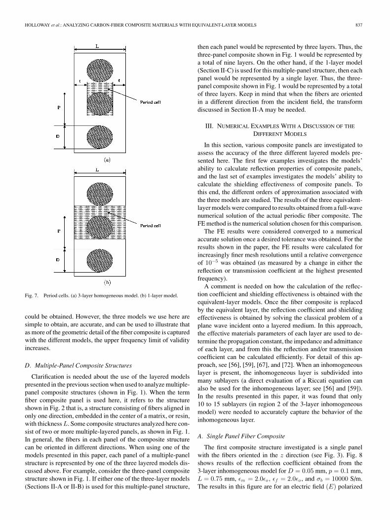
In this model, the composite panel shown in Fig. 2 is rep-resented by the 3-layer model shown in Fig. 3(b). This modeldiffers from the model in the previous section by the fact that thecenter layer is homogeneous (i.e., εeff is constant in region 2).Hence, it is named the 3-layer homogeneous model. In thismodel, layers 1 and 3 have a thickness t and constant materialproperties of εm . Layer 2 has a thickness of D and the materialproperties of this layer are given in (3). The fill factor g neededin these expressions for this 3-layer homogeneous model is con-stant, with y′, is simply the relative volume of space occupiedby the fiber in the period cell shown in Fig. 7(a), and is given by
g =πD2
4PD=
πD
4P. (7)
This model captures less detail of the fiber panel than the pre-vious 3-layer inhomogeneous model, and it will be shown thatin some cases the 3-layer homogeneous model is less accuratefor higher frequencies than the 3-layer inhomogeneous model.
C. 1-Layer Homogeneous Model
This is the simplest of the three models discussed in thispaper and consists of representing the fiber composite panelas a single-layer material [see Fig. 3(c)]. This single layer hasthickness L and the material properties of this layer are givenin expressions shown in (3). The fill factor g needed in theseexpressions for this model is constant, is the relative volume ofspace occupied by the fiber in the period cell shown in Fig. 7(b),and is given by
g =πD2
4PL. (8)
This type of model (i.e., modeling the single panel as one equiv-alent layer) is the approach used in the model presented byCasey [22], [23]. The difference between Casey’s model andour 1-layer model is in the expressions used for the effectiveproperties of the layer. This type of 1-layer model captures lessdetail of the fiber than the previous two 3-layer models, andit will be shown that this 1-layer homogeneous model is lessaccurate for higher frequencies than the two previous models.
The three models presented in Sections II-A–C are by nomeans the only effective layer models one could obtain. If dif-ferent forms of averaging are used, different effective parameters
HOLLOWAY et al.: ANALYZING CARBON-FIBER COMPOSITE MATERIALS WITH EQUIVALENT-LAYER MODELS 837
could be obtained. However, the three models we use here aresimple to obtain, are accurate, and can be used to illustrate thatas more of the geometric detail of the fiber composite is capturedwith the different models, the upper frequency limit of validityincreases.
D. Multiple-Panel Composite Structures
Clarification is needed about the use of the layered modelspresented in the previous section when used to analyze multiple-panel composite structures (shown in Fig. 1). When the termfiber composite panel is used here, it refers to the structureshown in Fig. 2 that is, a structure consisting of fibers aligned inonly one direction, embedded in the center of a matrix, or resin,with thickness L. Some composite structures analyzed here con-sist of two or more multiple-layered panels, as shown in Fig. 1.In general, the fibers in each panel of the composite structurecan be oriented in different directions. When using one of themodels presented in this paper, each panel of a multiple-panelstructure is represented by one of the three layered models dis-cussed above. For example, consider the three-panel compositestructure shown in Fig. 1. If either one of the three-layer models(Sections II-A or II-B) is used for this multiple-panel structure,
then each panel would be represented by three layers. Thus, thethree-panel composite shown in Fig. 1 would be represented bya total of nine layers. On the other hand, if the 1-layer model(Section II-C) is used for this multiple-panel structure, then eachpanel would be represented by a single layer. Thus, the three-panel composite shown in Fig. 1 would be represented by a totalof three layers. Keep in mind that when the fibers are orientedin a different direction from the incident field, the transformdiscussed in Section II-A may be needed.
III. NUMERICAL EXAMPLES WITH A DISCUSSION OF THE
DIFFERENT MODELS
In this section, various composite panels are investigated toassess the accuracy of the three different layered models pre-sented here. The first few examples investigates the models’ability to calculate reflection properties of composite panels,and the last set of examples investigates the models’ ability tocalculate the shielding effectiveness of composite panels. Tothis end, the different orders of approximation associated withthe three models are studied. The results of the three equivalent-layer models were compared to results obtained from a full-wavenumerical solution of the actual periodic fiber composite. TheFE method is the numerical solution chosen for this comparison.
The FE results were considered converged to a numericalaccurate solution once a desired tolerance was obtained. For theresults shown in the paper, the FE results were calculated forincreasingly finer mesh resolutions until a relative convergenceof 10−5 was obtained (as measured by a change in either thereflection or transmission coefficient at the highest presentedfrequency).
A comment is needed on how the calculation of the reflec-tion coefficient and shielding effectiveness is obtained with theequivalent-layer models. Once the fiber composite is replacedby the equivalent layer, the reflection coefficient and shieldingeffectiveness is obtained by solving the classical problem of aplane wave incident onto a layered medium. In this approach,the effective materials parameters of each layer are used to de-termine the propagation constant, the impedance and admittanceof each layer, and from this the reflection and/or transmissioncoefficient can be calculated efficiently. For detail of this ap-proach, see [56], [59], [67], and [72]. When an inhomogeneouslayer is present, the inhomogeneous layer is subdivided intomany sublayers (a direct evaluation of a Riccati equation canalso be used for the inhomogeneous layer; see [56] and [59]).In the results presented in this paper, it was found that only10 to 15 sublayers (in region 2 of the 3-layer inhomogeneousmodel) were needed to accurately capture the behavior of theinhomogeneous layer.
A. Single Panel Fiber Composite
The first composite structure investigated is a single panelwith the fibers oriented in the z direction (see Fig. 3). Fig. 8shows results of the reflection coefficient obtained from the3-layer inhomogeneous model for D = 0.05 mm, p = 0.1 mm,L = 0.75 mm, εm = 2.0εo , εf = 2.0εo , and σb = 10000 S/m.The results in this figure are for an electric field (E) polarized
838 IEEE TRANSACTIONS ON ELECTROMAGNETIC COMPATIBILITY, VOL. 47, NO. 4, NOVEMBER 2005
Fig. 8. Magnitude of the reflection coefficient for a single-layer fiber compositewith D = 0.05 mm, P = 0.1 mm, L = 0.75 mm, εm = 2.0εo , εf = 2.0εo ,and σ = 1 · 104 S/m.
in both the z and x direction. Also shown in this figure are thereflection coefficients obtained from the FE solution for an E-field propagating through the fiber composite. The comparisonto the numerical results indicate that the 3-layer inhomoge-neous model is quite accurate in approximating the reflectionsof the fiber composite. The strong anisotropic nature of thereflections indicate that this conducting fiber composite behaveslike an electromagnetic periodic grating [68]–[70]. When thewavelength is large compared to the period, incident E-fieldsparallel to the fibers will not penetrate the fiber composite andare totally reflected, whereas incident E-fields perpendicular tothe fibers are almost totally transmitted. Fig. 9 shows results ofthe same structure for various conductivities of the fibers (z-polarized). Once again, notice the excellent correlation betweenthe two solutions over a large frequency range and for variousvalues of σ.
This comparison indicates that the 3-layer inhomogeneousmodel is accurate, but what about less accurate models? Also inFig. 9 are the results obtained from the 1-layer model discussedin Section II-C. For this particular structure it is shown thatthe 1-layer model captures enough physical detail of the panelto be accurate for the frequencies shown. However, this is notthe case if the dimensions of the panel increase, if the structurebecomes more complicated, and/or if the frequency of operationis increased, as will be seen below.
The next composite structure in the investigation is a singlepanel with fibers oriented in the z direction (see Fig. 3) and fieldpolarized in the x direction. For this example D = 7.5 mm, P =15 mm, L = 15 mm, t = 3.75 mm, εm = 2.0εo , εf = 4.0εo ,and σ = 0. Fig. 10 shows the reflection coefficient obtained forthe three different models. Also shown in this figure are the
Fig. 9. Magnitude of the reflection coefficient for a single-layer fiber compositewith D = 0.05 mm, P = 0.1 mm, L = 0.75 mm, εm = 2.0εo , εf = 2.0εo ,and various values of σ.
Fig. 10. Magnitude of the reflection coefficient for a single-layer fiber compos-ite with D = 7.5 mm, P = 15 mm, L = 15 mm, t = 3.75 mm, εm = 2.0εo ,εf = 4.0εo , and σ = 0 S/m. λ is the wavelength in free space and the E-fieldis orthogonal to fibers.
results obtained from the FE solution. Notice that the 3-layerinhomogeneous model is the most accurate. The results for the3-layer homogeneous model start to break down at 4 GHz, andthe results for the 1-layer model start to break down at 2.5 GHz.Fig. 11 shows results for the same structure but for the E-fieldpolarized parallel to the fiber.
HOLLOWAY et al.: ANALYZING CARBON-FIBER COMPOSITE MATERIALS WITH EQUIVALENT-LAYER MODELS 839
Fig. 11. Magnitude of the reflection coefficient for a single-layer fiber compos-ite with D = 7.5 mm, P = 15 mm, L = 15 mm, t = 3.75 mm, εm = 2.0εo ,εf = 4.0εo , and σ = 0 S/m. λo is the wavelength in free space and the E-fieldis parallel to fibers.
B. Multiple Panel Fiber Composite
The examples up to this point have been for single compositepanels (see Fig. 2). The real distinction between the three differ-ent models is seen for more complicated composite structures.In the next example, the two-panel composite shown in Fig. 12is analyzed. In this structure, the fibers in the two panels arealigned orthogonal to one another. One set of fibers is alignedalong the x-axis and the other is aligned along the z-axis. Foreach panel, D = 7.5 mm, P = 15 mm, L = 15 mm, t = 3.75mm, εm = 2.0εo , εf = 4.0εo , and σ = 0 S/m. Each panel ofthis two-panel composite structure is replaced with the threedifferent models discussed in Section II. For the 3-layer inho-mogeneous model and the 3-layer homogeneous model, eachpanel is represented by three layers. Therefore, the two-panelstructure is modeled by a total of six-layers, referred to as thesix-layer inhomogeneous model and the six-layer homogeneousmodel, respectively. While for the 1-layer model, two differentlayers are used for the two-layered composite panel, resultingin a total of two layers and referred to as a two-layer model inthis example. Fig. 13 shows the reflection coefficient obtainedfrom our three models. Also shown in this figure are the resultsobtained from the FE solution. The six-layer inhomogeneousmodel is very accurate at frequencies up to about 9.5 GHz,while the other two models break down at lower frequencies.The two-layer panel model breaks down at about 3 GHz, and thesix-layer homogeneous model breaks down at about 7.5 GHz.
The reason why the different models break down at differentfrequencies can be explained by physical arguments. Note thatfor frequencies up to 10 GHz, the reflection coefficients experi-ence several resonances. The different models exhibit differentresonant behaviors, which are a direct result of the number
Fig. 12. Two-layer fiber composite with D = 7.5 mm, P = 15 mm, L = 15mm, t = 3.75 mm, εm = 2.0εo , εf = 4.0εo , and σ = 0 S/m. The angles inthe figure indicate the orientation of the fibers in the xz plane relative to thex-axis.
Fig. 13. Magnitude of the reflection coefficient for a two-layer fiber com-posite with D = 7.5 mm, P = 15 mm, L = 15 mm, t = 3.75 mm, εm =2.0εo , εf = 4.0εo , σ = 0 S/m. The E-field is polarized in the x direction, withthe fibers in the first layer aligned perpendicular in the incident field and thefibers in the second layer aligned parallel to the incident field.
and thickness of each layer used in the different models. Thesedifferent models will capture different levels or orders of theresonant phenomenon in the two-panel composite structure.
To illustrate this point, let us look at how each panel of thetwo-panel composite structure is modeled. For example, wheneach panel is modeled as a single layer, the resonance in eachpanel is governed by the single layer thickness of 15 mm. On theother hand, when each panel is modeled with either the 3-layerinhomogeneous or 3-layer homogeneous model, the resonancein each panel is governed by the resonance of a three-layermedium. In the true composite panel, there is a complicated res-onant behavior resulting from the wave propagating through thepanel. First of all, once the wave enters the panel and propagates
840 IEEE TRANSACTIONS ON ELECTROMAGNETIC COMPATIBILITY, VOL. 47, NO. 4, NOVEMBER 2005
toward the fibers, a reflection occurs at the location of the fibersurface. The wave continues to propagate across the fibers, anda reflection will occur at the point the fibers end. Continuous re-flections will occur as the wave propagates across the inhomoge-neous fiber region (i.e., the wave sees different cross-sections ofthe fiber as it propagates across the fiber). This complicated fieldinteraction is best represented by the inhomogeneous model, asseen is Fig. 13. The 3-layer homogeneous model captures mostof the layered resonant phenomenon, but does not capture theresonance that occurs as the wave propagates across the fiber.
The importance of capturing more detail of a layered compos-ite panel, especially at higher frequencies, is emphasized next.One approach that can be used to model a multiple-panel com-posite structure is to model the entire multiple-panel structureas a single layer, regardless of the number of fiber panels. Sucha model would be valid only at very low frequencies since noneof the layered resonances would be captured. For example, thetwo-panel composite shown in Fig. 12 could be modeled as asingle layer of thickness equal to 2L, with the material propertiesgiven by [58] and [71]
εeff =√
εxεz (9)
where εx and εz are given in (3), and the value of g needed in (3)is given in (8). In such a simple model, the strong anisotropicnature of the orthogonal-oriented fiber is averaged out by thegeometric mean of the two orthogonal material properties (i.e.,εx and εz ). Fig. 13 shows the results for this simple single-layer model of the two-panel composite structure compared tothe other models and to the FE results. The single-layer modelcannot capture the complicated resonances of the two-panelcomposite structure. Therefore, as expected, the model that cap-tures more of the fundamental resonances of the multiple-panelstructure (i.e., the inhomogeneous model) is more accurate asfrequencies increase. These points are further illustrated in forth-coming examples.
We now turn our attention to calculating shielding effective-ness (SE) with these equivalent layer models. SE is defined asthe ratio (in decibel units) of the transmitted E-field through acomposite to the incident E-field
SE = −20Log10
(|Et ||Ei |
)(10)
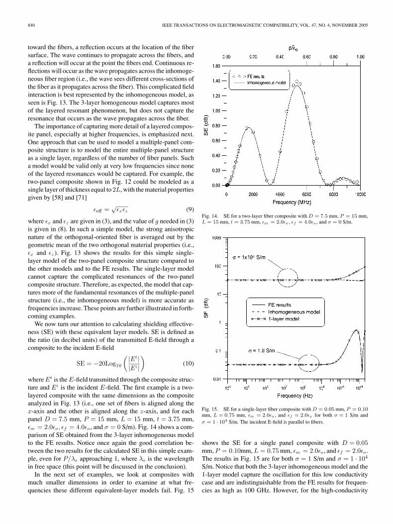
where Et is the E-field transmitted through the composite struc-ture and Ei is the incident E-field. The first example is a two-layered composite with the same dimensions as the compositeanalyzed in Fig. 13 (i.e., one set of fibers is aligned along thex-axis and the other is aligned along the z-axis, and for eachpanel D = 7.5 mm, P = 15 mm, L = 15 mm, t = 3.75 mm,εm = 2.0εo , εf = 4.0εo , and σ = 0 S/m). Fig. 14 shows a com-parison of SE obtained from the 3-layer inhomogeneous modelto the FE results. Notice once again the good correlation be-tween the two results for the calculated SE in this simple exam-ple, even for P/λo approaching 1, where λo is the wavelengthin free space (this point will be discussed in the conclusion).
In the next set of examples, we look at composites withmuch smaller dimensions in order to examine at what fre-quencies these different equivalent-layer models fail. Fig. 15
Fig. 14. SE for a two-layer fiber composite with D = 7.5 mm, P = 15 mm,L = 15 mm, t = 3.75 mm, εm = 2.0εo , εf = 4.0εo , and σ = 0 S/m.
Fig. 15. SE for a single-layer fiber composite with D = 0.05 mm, P = 0.10mm, L = 0.75 mm, εm = 2.0εo , and εf = 2.0εo for both σ = 1 S/m andσ = 1 · 104 S/m. The incident E-field is parallel to fibers.
shows the SE for a single panel composite with D = 0.05mm, P = 0.10mm, L = 0.75 mm, εm = 2.0εo , and εf = 2.0εo .The results in Fig. 15 are for both σ = 1 S/m and σ = 1 · 104
S/m. Notice that both the 3-layer inhomogeneous model and the1-layer model capture the oscillation for this low conductivitycase and are indistinguishable from the FE results for frequen-cies as high as 100 GHz. However, for the high-conductivity
HOLLOWAY et al.: ANALYZING CARBON-FIBER COMPOSITE MATERIALS WITH EQUIVALENT-LAYER MODELS 841
Fig. 16. SE for a four-panel fiber composite with each panel of the compos-ite having D = 0.05 mm, P = 0.10 mm, L = 0.75 mm, εm = 2.0εo , andεf = 2.0εo for both σ = 1 S/m and σ = 1 · 104 S/m. The incident E-field isorthogonal to the fibers in the first panel.
case, the 1-layer model fails at a frequency that is about an or-der of magnitude lower than where the 3-layer inhomogeneousmodel breaks down. Thus, we see that as the conductivity in-creases, the inhomogeneous model performs better at capturingthe internal resonances than does the 1-layer model.
For multiple-panel fiber composites, the internal resonancesof the different layers become important, and the 1-layer modelcannot capture this behavior, whereas the 3-layer inhomoge-neous model does an excellent job of representing the multiple-panel composite. This is illustrated in the final examples. Thestructure analyzed next consists of four panels with fibers ori-ented in different directions. In the first panel, the fibers areoriented along the x-axis. In the second panel, the fibers are ori-ented along the z-axis. The third panel has fibers oriented alongthe x-axis, and the last panel has fibers oriented along the z-axis.For each panel L = 0.75 mm, D = 0.05 mm, P = 0.10mm, andεm = εf = 2εo . Each panel of the four-panel structure is rep-resented by one of the three models discussed in Section II.The SE obtained from two of these models is shown in Fig. 16for both σ = 1 S/m and σ = 1 · 104 S/m. Also shown in thesefigures are the FE results. Notice that for the low-conductivitycase, both the inhomogeneous model and the 1-layer modelproduce very good correlation. On the other hand, for the high-conductivity case, the 1-layer model fails at about 2 GHz, whileresults from inhomogeneous model are indistinguishable (evencapturing the resonances) from the FE results for frequencies ashigh as 100 GHz. Comparison to the numerical results indicatethat the inhomogeneous model is quite accurate in approximat-ing the SE of the multiple-panel fiber composite. We see thatas the conductivity becomes higher, the inhomogeneous modeldoes a much better job than the 1-layer model of capturing the
Fig. 17. SE for a two-panel fiber composite with each panel of the compos-ite having D = 0.05 mm, P = 0.10 mm, L = 0.75 mm, εm = 2.0εo , andεf = 2.0εo for both σ = 1 S/m and σ = 1 · 104 S/m. The incident E-field isorthogonal to the fibers in the first panel.
internal resonances of this multiple-panel composite structure,especially for the higher frequencies.
Similar conclusions as above can be made about a two-panelcomposite structure. Fig. 17 shows the SE for a two-panel com-posite structure where for each panel L = 0.75 mm, D = 0.05mm, P = 0.10 mm, and εm = εf = 2εo . As in the last exam-ple, notice that for the low-conductivity case, both the inho-mogeneous model and the 1-layer model produce very goodcorrelation. On the other hand, for the high-conductivity case,the 1-layer model fails at about 2 GHz, while results fromthe inhomogeneous model are indistinguishable (even capturingthe resonances) from the FE results for frequencies as high as100 GHz. Once again this indicates that the inhomogeneousmodel is quite accurate in approximating the SE of the multiple-panel fiber composite. Each individual panel for the three com-posite structures analyzed in Figs. 15–17 are the same. Thedifference is in the total number of panels. It is interesting toobserve the results in these three figures; we see that, as thenumber of panels increases (i.e., an increase in the total thick-ness of the composite structure), the frequency location of thefirst resonance in the response of the composite decreases.
The results presented here are for normal incidence only.However, the tensor representation of ε and µ, as shown is (1) and(2), makes the effective parameters work for arbitrary incidenceangles. For more details on this point, see [56] and discussionsin [58]. Note, however, that as the incidence angle changes from0◦ (normal incidence) to ∼90◦ (close to grazing incidence), themaximum period for which the effective parameters will workis decreased, since grating lobes (the first-order Floquet modes)will appear “earlier” for near-grazing incidence. The last sectionof this paper addresses this in more detail.
842 IEEE TRANSACTIONS ON ELECTROMAGNETIC COMPATIBILITY, VOL. 47, NO. 4, NOVEMBER 2005
IV. TRANSITION BOUNDARY CONDITIONS
The equivalent homogeneous formulation of the materialproperties is also very useful in numerical codes for the analysisof field penetration (shielding effectiveness) inside compositestructures, eliminating the need to spatially resolve the fibers.With these effective layer models, it is possible to develop ef-ficient transfer-matrix boundary conditions (TMBC) for largecomputational codes for analyzing EM coupling for variousproblems, including coupling into composite structures (for de-tails, see [9] and [72]). In these papers, a technique for devel-oping efficient transform matrices for the transfer impedanceand admittance of layer composites is presented. The use of theTMBC eliminates the need to spatially resolve the fine detailsof the composite material which decreases the computationalrun-time of the coupling problem.
The TMBC approach still requires a solution of a layeredmedium in its implementation. An alternative is the use of ageneralized impedance boundary condition (GIBC) in whichthe composite structure would be replaced with a transitionboundary condition without the need to solve a layered medium.Two examples of these types of GIBC are found in [73], [74],and [75], where GIBCs have been developed for analyzing scat-tering of metafilms (the two-dimensional equivalent of metama-terials) [74], and analyzing scattering from conducting roughsurfaces [73] and [75]. In the GIBC, the scattering effects arerepresented by effective electrical and magnetic polarizabilitydensities. Presently, we are continuing the work in [73]–[75] inorder to develop GIBC for thin fiber composites.
V. CONCLUSION
In this paper, we have presented three different equivalent-layer models for the effective material properties of fiber com-posite structures. These models can be used to efficiently calcu-late the reflection and transmission coefficients, as well as theshielding effectiveness, of fiber composites. Each of these threemodels captures different levels of detail of the fiber compositepanel, and as such the three models break down at different fre-quencies. The paper discussed how the different models capturedifferent levels of accuracy associated with the resonance phe-nomenon of the panel composite. The most accurate of the threemodels presented here is the 3-layer inhomogeneous model. Wecompared and contrasted the three equivalent-layer models withresults obtained from the FE numerical method. Comparisonsto the FE results indicate that the 3-layer inhomogeneous modelis quite accurate in approximating the reflection coefficient andthe SE of the multiple-panel fiber composite.
We have discussed how these different models capture thephysical resonance behavior of the fiber composite panel in var-ious ways. As such, we have illustrated some of the deficienciesof equivalent-layer models for the analysis of fiber compositesand have shown that the 3-layer inhomogeneous model extendsthe use of the equivalent-layers to higher frequencies. The in-homogeneous model does a much better job of capturing theinternal resonances of this multiple-panel composite structurethan the 1-layer model, especially for higher frequencies andconductivities. We showed that for multiple-panel fiber com-
posites, the internal resonances of the different layers becomeimportant, and the 1-layer model cannot capture this behavior,whereas the 3-layer inhomogeneous model does an excellent jobof simulating the behavior of the multiple-panel composites.
In previous work [56], [58], [76], it was shown that repre-senting a periodic structure as an equivalent-layer is valid aslong as the period is small compared to the wavelength in thedense material. This is demonstrated in Figs. 13 and 14, whereeven the 3-layer inhomogeneous model breaks down at 9.5 GHz(where P/λ is approaching 1). However, the period of the struc-ture analyzed in Figs. 15 and 16 is small enough such that, evenat 10 GHz, the equivalent-layer models are still accurate.
When the fiber rods become highly conducting, fine localvariations in the fields develop in the vicinity of the rods. Thisso-called boundary-layer behavior of the fields cannot be han-dled properly with standard homogenization techniques; as a re-sult, an equivalent-layer model would not be valid (as discussedin [76] for a related periodic structure). When boundary layerfields are present, modifications of standard homogenizationtechniques are required. Such a modification to the homogeniza-tion technique has been applied to highly conducting periodicrough surfaces [73]. We are presently extending this work toanalyze propagation through concrete with reinforced metal re-bar and other highly conducting periodic structures, which willallow the analysis of highly conducting fiber composites. Noticethat the period of the fibers analyzed in Figs. 13 and 14 is smallenough compared to a wavelength such that the boundary-layerfields behavior is not influencing the results from the equivalent-layer model. However, once the period of this structure becomescomparable to a wavelength, the boundary-layer field behaviorwill become important. The effect of the so-called boundary-layer fields resulting from highly conducting fibers can have aninfluence on the accuracy of the equivalent-layer model, whichwe begin to see in the high-conductivity case of Fig. 15. Weare presently trying to quantify the value of P/λ where thisoccurs. In fact, we have found that for highly conducting com-posite structures, the effective-material properties can becomebianisotropic or chiral in nature. Details will be published else-where. Finally, other techniques are also being investigated inorder to extend the range of these equivalent-layer models. Forexample, techniques for taking into account the currents flowingon the conducting fibers are presented in [77].
REFERENCES
[1] R. E. Evans, D. E. Hall, and B. A. Luxon, “Nickel coated graphite fiberconductive composites,” Sampe Quarterly, vol. 17, no. 4, 1986.
[2] J. R. Gaier and J. Terry, “EMI shields made from intercalated graphitecomposites,” in Proc. 7th Int. SAMPE Electronics Conf., vol. 7, Parsip-pany, NJ, Jun. 20–23, 1994, pp. 221–233, Critical Materials and Processesin a Changing World.
[3] H.-C. Chu, S.-K. Jeng, and C.-H. Chen, “Reflection and transmission char-acteristics of lossy periodic composite structures,” IEEE Trans. AntennasPropag., vol. 44, no. 3, pp. 580–587, Mar. 1996.
[4] K. Naishadham, “Shielding effectiveness of conductive polymers,” IEEETrans. Electromagn. Compat., vol. 34, no. 1, pp. 47–50, Feb. 1992.
[5] L. A. Pilato and M. J. Michno, Advanced Composite Materials. Berlin:Springer-Verlag, 1994.
[6] H. M. Flower, High Performace Materials in Aerospace. Chapman & Hall,1995.
HOLLOWAY et al.: ANALYZING CARBON-FIBER COMPOSITE MATERIALS WITH EQUIVALENT-LAYER MODELS 843
[7] R. W. Evans, “Design Guidelines for Shielding Effectiveness, CurrentCarrying Capability, and the Enhancement of Conductivity of CompositeMaterials,” NASA Contractor Report, no. 4784, Aug. 1997.
[8] M. S. Sarto, S. Di Michele, and P. Leerkamp, “Electromagnetic perfor-mance of innovative lightweight shields to reduce radiated emissions fromPCBs,” IEEE Trans. Electromagn. Compat., vol. 44, no. 2, pp. 353–363,May 2002.
[9] M. D’Amore and M. S. Sarto, “Theoretical and experimental characteri-zation of the EMP-interaction with composite-metallic enclosures,” IEEETrans. Electromagn. Compat., vol. 42, pp. 152–163, May 2000.
[11] Methods and Technologies for Aircraft Safety and Protection AgainstElectromagnetic Hazards (EM-HAZ), 1999 Fifth Framework Program,Growth Programme, RTD Contract Ref. G4RD-CT-1999-00093.
[12] Analysis of Experimental Data and Models for Upgraded LightningProtection Requirements (FULMEN), 1996 Fourth Framework Program,Transport, RTD Programme.
[13] Creation of a New Fully Conducting Thermoplastic Polymeric for Aero-nautics, Electronics and Telecommunications Industries Fourth Frame-work Program, Brite/Euram 3, BRST970748.
[14] R. W. Evans, “Test Report 3/4 Direct and Indirect Lightning Effects onComposite Materials,” NASA Contractor Report, no. 4783, Jul. 1997.
[15] “Test Report 3/4 Fault Current Through Graphite Filament Rein-forced Plastics,” NASA Contractor Report, no. 4774, Apr. 1997.
[16] Aircraft Lightning Protection Handbook. F. A. Fisher, and J. A. Plumer,eds., Federal Adviation Administration, Dept. of Transportation, Rep. no.DOT/FAA/CT-89/22, Sep. 1989.
[17] M. D’Amore and M. S. Sarto, “Numerical modeling of lightning tests onthin advanced composite panels,” in Proc. 23rd Int. Conf. on LightningProtection—ICLP, Firenze, Sep. 23–27, 1996.
[18] , “Time-domain analysis of lightning interaction to aeronautical struc-tures composite materials,” in Proc. 1997 IEEE Int. Symp. ElectromagneticCompat., Austin, TX, Aug. 18–22, 1997, pp. 397–402.
[19] , “Time-domain analysis of the lightning induced effects on wirenetworks inside carbon fiber composite enclosures,” in Proc. Int. Conf.Lightning Protection—ICLP 2000, Rhodos, Greece, Sep. 2000.
[20] V. Volpi, M. Apr., M. D’Amore, M. S. Sarto, and A. Scarlatti, “Lightningstroke to a metallic-composite aircraft: Certification feasibility by simula-tion. Part I: Prediction of the electromagnetic field,” in Proc. EMC Europe2000 Brugge: 4th Int. Symp. EMC, Brugge, Belgium, Sep. 11–15, 2000,pp. 173–178.
[21] M. D’Amore and M. S. Sarto, “Experimental characterization of EMdiffusion through metallic-composite enclosures excited by impulsivecurrent injection,” in Proc. Int. Conf. Electromagnetics in AdvancedApplications—ICEAA’99, Torino, Italy, Sep. 13–17, 1999, pp. 693–696.
[22] K. F. Casey, “EMP Penetration Through Advanced Composite Skin Pan-els,” Interaction Notes 315, Dec. 1976.
[23] , “Advanced composite materials and electromagnetic shielding,”in Proc. 1978 IEEE Int. Symp. EMC, Atlanta, GA, Jun. 20–22, 1978,pp. 228–232.
[24] C. L. Holloway, M. Johansson, and M. S. Sarto, “An effective layermodel for analyzing fiber composites,” in Proc. Int. Symp. ElectromagneticCompat., EMC’98 ROMA, Rome, Italy, Sep. 14–18, 1998.
[25] A. N. Lagarkov and A. K. Sarychev, “Electromagnetic properties of com-posites containing elongated conducting inclusions,” Phys. Rev. B Con-dens. Matter, vol. 53, no. 10, pp. 6318–6335, Mar. 1996.
[26] M. S. Lin and C. H. Chen, “Transient propagation in anisotropic laminatedcomposites,” IEEE Trans. Electromagn. Compat., vol. 35, no. 3, pp. 357–364, Aug. 1993.
[27] H. C. Chu and C. H. Chen, “Shielding and reflection properties of periodicfiber-matrix composite structures,” IEEE Trans. Electromagn. Compat.,vol. 38, no. 1, pp. 1–6, Feb. 1996.
[28] C. N. Chiu and C. H. Chen, “Plane-wave shielding properties of anisotropiclaminated composite cylindrical shells,” IEEE Trans. Electromagn. Com-pat., vol. 37, no. 1, pp. 109–113, Feb. 1995.
[29] P. M. McKenna, T. H. Rudolph, and R. A. Perala, “A time domain rep-resentation of surface and transfer impedances useful for analysis of ad-vanced composite aircraft,” in Proc. 1984 Int. Conf. Lightning and StaticElectricity, Orlando, FL, Jun. 1984, pp. 37.1–37.6.
[30] M. S. Sarto, “A new model for the FDTD analysis of the shielding perfor-mances of thin composite structures,” IEEE Trans. Electromagn. Compat.,vol. 41, no. 4, pp. 298–306, Nov. 1999.
[31] M. S. Sarto, “Hybrid MFIE/FDTD analysis of the shielding effectivenessof a composite enclosure excited by a transient plane wave,” IEEE Trans.
Magn., vol. 36, no. 4, pp. 946–950, Jul. 2000.[32] , “A matrix surface impedance formulation for the analysis of EM-
interactions to finite laminated composite slabs,” in Proc. 1996 IEEE Int.Symp. EMC, CA, Aug. 23–27, 1996, pp. 168–173.
[33] , “FDTD analysis of field penetration inside thin composite shells,”in Proc. 1998 URSI Electromagnetic Theory Symp., Thessaloniki, Greece,May 24–28, 1998, pp. 674–676.
[34] M. S. Sarto and C. L. Holloway, “On the use of a hybrid MFIE/FDTDmethod for the analysis of electromagnetic scattering and coupling prob-lems,” in Proc. 2000 IEEE Int. Symp. EMC, Washington, DC, Aug. 2000,pp. 801–806.
[35] J. A. Cole, J. F. Dawson, and S. J. Porter, “Efficient modelling of thinconducting sheets within the TLM method,” in Proc. IEE 3rd Int. Conf.Computation in Electromagnetics, Bath, Apr. 10–12, 1996, pp. 45–50.
[36] , “A digital filter technique for electromagnetic modelling of thincomposite layers in TLM,” in Proc. 13th Annual Review of Progress inApplied Computational Electromagnetics, Monterey, CA, Mar. 17–21,1997, pp. 686–693.
[37] A. C. Cangellaris and C. Jin, “Macro-elements for accurate dispersivemodeling of thin material sheets and impedance boundary conditions inFDTD,” in Proc. 13th Int. Zurich Symp. on EMC, Zurich, Switzerland,Feb. 16–18, 1999, pp. 357–362.
[38] C. L. Holloway, D. Hill, J. Ladbury, G. Koepke, and R. Garzia, “Shieldingeffectiveness measurements of materials in nested reverberation cham-bers,” IEEE Trans. Electromagn. Compat., vol. 44, no. 2, pp. 350–356,May 2002.
[39] J. Baker-Jarvis, “Transmission/Reflection and Short Circuit Permittiv-ity Measurements,” U.S. Department of Commerce, Boulder, CO, NISTTechnical Note, no. 1341, Jul. 1990.
[40] J. A. Catrysse, M. de Goeije, W. Steenbakkers, and L. Anaf, “Correlationbetween shielding effectiveness measurements and alternative methodsfor the characterization of shielding materials,” IEEE Trans. Electromagn.Compat., vol. 35, no. 4, pp. 440–444, Nov. 1993.
[41] B. J. Cahill, A. C. Marvin, and J. F. Dawson, “Complex permittivitymeasurement of foam materials using a one-port network analyser mea-surement,” in Proc. Int. Symp. Electromagnetic Compatibility, EMC’98ROMA, Rome, Italy, Sep. 14–18, 1998, pp. 505–510.
[42] C. L. Gardner and Y. F. C. Poissant, “Measurement of the shielding prop-erties of composite materials: Comparison of the dual TEM and noncon-tact probe-methods,” IEEE Trans. Electromagn. Compat., vol. 40, no. 4,pp. 364–369, Nov. 1998.
[43] “Standard method for measuring the electromagnetic shielding effective-ness of planar materials,” reprinted from the Annual Book of ASTM Stan-dards in AMST Commmittee D-9, ASTM D-4935, Sep. 1989.
[44] “ASTM-ES7 and ASTM-D4935 standard for measuring the shieldingeffectiveness in the far field,” 1995 Annual Book of ASTM Standards,vol. 10.02, 1995.
[45] P. F. Wilson and M. T. Ma, “A Study of Techniques for Measuring theElectromagnetic Shielding Effectiveness of Materials,” U.S. Dep. of Com-merce, National Bureau of Standards, Boulder, CO, NBS Tech. Note 1095,1986.
[46] , “Techniques for measuring the electromagnetic shielding effec-tiveness of materials: Part I: Far-field source simulation,” IEEE Trans.Electromagn. Compat., vol. 30, no. 3, pp. 239–250, Aug. 1988.
[47] J. Baker-Jarvis and M. D. Janezic, “Analysis of a two-port flanged coaxialholder for shielding effectiveness and dielectric measurements of thinfilms and thin materials,” IEEE Trans. Electromagn. Compat., vol. 38,no. 1, pp. 67–70, Feb. 1996.
[48] P. F. Wilson and M. T. Ma, “Techniques for measuring the electromagneticshielding effectiveness of materials: Part II: Near-field source simulation,”IEEE Trans. Electromagn. Compat., vol. 30, no. 3, pp. 251–259, Aug.1988.
[49] M. O. Hatfield, “Shielding effectiveness measurements using mode-stirredchambers: A comparison of two approaches,” IEEE Trans. Electromagn.Compat., vol. 30, no. 3, pp. 229–238, Aug. 1988.
[50] W. Kurner and A. Schwab, “Parameters and results of SE-measurementsperformed in mode-stirred chambers,” in Proc. 2000 IEEE Int. Symp. Elec-tromagnetic Compatibility, Washington, DC, Aug. 21–25, 2000, pp. 611–614.
[51] T. A. Loughry and S. H. Gurbazani, “The effects of intrinsic test fixtureisolation on material shielding effectiveness measurements using nestedmode-stirred chambers,” IEEE Trans. Electromagn. Compat., vol. 37,no. 3, pp. 449–452, Aug. 1995.
[52] A. Manara, “Measurement of material shielding effectiveness using adual TEM cell and vector network analyzer,” IEEE Trans. Electromagn.Compat., vol. 38, no. 3, pp. 327–333, Aug. 1996.
844 IEEE TRANSACTIONS ON ELECTROMAGNETIC COMPATIBILITY, VOL. 47, NO. 4, NOVEMBER 2005
[53] D. S. Dixon and J. Masi, “Thin coatings can provide significant shieldingagainst low frequency EMF/magnetic fields,” in Proc. 1998 IEEE Int.Symp. Electromagnetic Compatibility, Denver, CO, Aug. 24–28, 1998,pp. 1035–1040.
[54] J. R. Gaier, W. C. Hardebeck, J. R. T. Bunch, M. L. Davidson, and D.B. Beery, “Effect of intercalation in graphite epoxy composites on theshielding of high energy radiation,” J. Mater. Res., vol. 13, no. 8, pp. 2297–301, Aug. 1998.
[55] C. Caneva, F. Nanni, and M. S. Sarto, “Electromagnetic and mechanicalproperties of a new composite material” in Proc. Int. Symp. on Electro-magnetic Compatibility, EMC’98 ROMA, Rome, Italy, Sep. 14–18, 1998.
[56] E. F. Kuester and C. L. Holloway, “A low-frequency model for wedgeand pyramidal absorbers-I: Theory,” IEEE Trans. Electromagn. Compat.,vol. 36, no. 4, pp. 300–306, Nov. 1994.
[57] C. L. Holloway and E. F. Kuester, “A low-frequency model for wedge andpyramidal absorbers—II: Computer and measured results,” IEEE Trans.Electromagn. Compat., vol. 36, no. 4, pp. 307–313, Nov. 1994.
[58] M. Johansson, C. L. Holloway, and E. F. Kuester, “Effective electro-magnetic properties of honeycomb composite, and hollow pyramidal andalternating wedge absorbers,” IEEE Trans. Antennas Propag., vol. 53,no. 2, pp. 728–736, Feb. 2005.
[59] C. L. Holloway, R. R. DeLyser, R. F. German, P. McKenna, and M. Kanda,“Comparison of electromagnetic absorber used in anechoic and semi-anechoic chambers for emissions and immunity testing of digital devices,”IEEE Trans. Electromagn. Compat., vol. 39, no. 1, pp. 33–47, Feb. 1997.
[60] Handbook of Electromagnetic Materials: Monolithic and Composite Ver-sions and Their Applications, P. S. Neelakanta ed., CRC Press, BocaRaton, FL, 1995.
[61] A. H. Sihvola, Electromagnetic Mixing Formulas and Application. Lon-don, U.K.: IEE, 1999.
[62] E. F. Kuester and C. L. Holloway, “Comparison of approximations foreffective parameters of artificial dielectrics,” IEEE Trans. Microw. TheoryTech., vol. 38, no. 11, pp. 1752–1755, Nov. 1990.
[63] O. Wiener, “Lamellare Doppelbrechung,” Phys. Z., vol. 5, pp. 332–338,1904.
[64] H.-G. Haddenhorst, “Durchang von elektromagnetischen Wellen durchinhomogene Schichten,” Z. Angew. Phys., vol. 7, pp. 487–496, 1955.
[65] S. M. Rytov, “Electromagnetic properties of a finely stratified medium,”Zh. Eksp. Teor. Fiz., vol. 29, pp. 605–616, 1955. (in Russian), (Englishtrans. in Sov. Phys., JETP, vol. 2, pp. 466–475, 1956).
[66] R. Pottel, “Absorption elektromagnetischer zeentimeterwellen in kunstlichanisotropen Medien,” Z. Angew. Phys., vol. 10, pp. 8–16, 1958.
[67] L. M. Brekhovskikh, Wave in Layered Media. New York: Academic, 1960,pp. 79–86, 215–233.
[68] T. Larsen, “A survey of the theory of wire grids,” IRE Trans. Microw.Theory Tech., vol. 10, no. 3, pp. 191–201, May 1962.
[69] Waveguide Handbook, N. Marcuvitz, Ed., Boston Technical Publishers,Lexington, MA, 1964, pp. 88–89, 280–285.
[70] L. A. Wainshtien, “On the electrodynamic theory of grids,” in High-PowerElectronics. Oxford: Pergamon Press, 1966, pp. 14–48.
[71] J. Nevard and J. Keller, “Reciprocal relations for effective conductivitesof anistotropic media,” J. Math. Phys., vol. 26, no. 11, pp. 2761–2765,1895.
[72] M. S. Sarto and C. L. Holloway, “Effective boundary conditions for thetime-domain analysis of the EMC performances of fiber composites,” inProc. IEEE 1999 Int. Symp. Electromagnetic Compatibility, Seattle, WA,Aug. 2–6, 1999, pp. 462–467.
[73] C. L. Holloway and E. F. Kuester, “Impedance-type boundary condi-tions for periodic interface between a dielectric and a highly conductingmedium,” IEEE Trans. Antenna Propag. Special Issue Honoring J. R.Wait, vol. 48, no. 10, pp. 1660–1672, Oct. 2000.
[74] E. F. Kuester, M. A. Mohamed, and C. L. Holloway, “Averaged transitionconditions for electromagnetic fields at a metafilm,” IEEE Trans. AntennasPropag. (Special Issue on Metamaterials), vol. 51, no. 10, pp. 2641–2651,Oct. 2003.
[75] C. L. Holloway and E. F. Kuester, “The homogenization-based derivationof effective boundary conditions for perfectly conducting periodic surfaceswith a cover layer,” Radio Sci., vol. 35, no. 3, pp. 661–681, May–Jun. 2000.
[76] C. L. Holloway, P. McKenna, and R. R. DeLyser, “A numerical investi-gation on the accuracy of the use of homogenization for analyzing peri-odic absorbing arrays,” in Proc. 1995 Int. Symp. Electromagnetic Theory,St.Petersburg, Russia, 1995, pp. 296–298.
[77] M. Parise and M. S. Sarto, “Efficient formulation of high-order bound-ary conditions for the high-frequency modeling of multilayer compositeslabs,” in Proc. 2003 IEEE Symp. Electromagentic Compatibility, Boston,MA, Aug. 11–22, 2003, pp. 753–758.
Christopher L. Holloway (S’86–M’92–SM’04) wasborn in Chattanooga, TN, on March 26, 1962. Hereceived the B.S. degree from the University of Ten-nessee at Chattanooga in 1986, and the M.S. andPh.D. degrees in electrical engineering from the Uni-versity of Colorado at Boulder in 1988 and 1992,respectively.
During 1992, he was a Research Scientist withElectro Magnetic Applications, Inc., in Lakewood,CO. His responsibilities included theoretical analysisand finite-difference time-domain modeling of var-
ious electromagnetic problems. From the fall of 1992 to 1994, he was withthe National Center for Atmospheric Research (NCAR) in Boulder, CO. Whileat NCAR, his duties included wave propagation modeling, signal processingstudies, and radar systems design. From 1994 to 2000, he was with the Institutefor Telecommunication Sciences (ITS) at the U.S. Department of Commerce inBoulder, CO, where he was involved in wave propagation studies. Since 2000,he has been with the National Institute of Standards and Technology (NIST),Boulder, CO, where he works on electromagnetic theory. He is also on theGraduate Faculty at the University of Colorado at Boulder.
Dr. Holloway was awarded the 1999 Department of Commerce Silver Medalfor his work in electromagnetic theory and the 1998 Department of CommerceBronze Medal for his work on printed circuit boards. His research interestsinclude electromagnetic field theory, wave propagation, guided wave structures,remote sensing, numerical methods, and EMC/EMI issues. He is a member ofCommission A of the International Union of Radio Science and is an Asso-ciate Editor for the IEEE Transactions on Electromagnetic Compatibility. Dr.Holloway is the chairman for the Technical Committee on Computational Elec-tromagnetics (TC-9) of the IEEE Electromagnetic Compatibility Society.
He is presently serving as a Distinguished Lecturer of the IEEE EMC Society.
Maria Sabrina Sarto (M’93–SM’00) received thePh.D. degree in electrical engineering from the Uni-versity of Rome “La Sapienza” in 1997.
She has been Associate Professor of Electrotech-nics since 1998, Head of the EMC Laboratory of theDepartment of Electrical Engineering since 1999, andFull Professor of Electrotechnics since 2005. She isauthor of over ninety technical and scientific papers,covering several EMC topics. Her recent research in-terests include shielding, nanotechnology, compositematerials and thin films, EMC on aircraft, and numer-
ical modeling. She received the IEEE EMC Society Past President’s MemorialAwards in 1996 and 1997, the 1997 and the 2000 Prize Paper Award of IEEETransactions on Electromagnetic Compatibility, and the SAE Wright BrothersMedal Award in 2001.
Prof. Sarto has been Associate Editor of the IEEE TRANSACTIONS ON
ELECTROMAGNETIC COMPATIBILITY since 1999. She was Distinguished Lec-turer of the IEEE EMC Society in 2001–2002. She is Chairman of the WorkingGroup IEEE Std. 299, Representative of the IEEE EMC Society in the Nanotech-nology Council for the years 2005–2006, and Chairman of the NanotechnologyWorking Group of AEIT-ASTRI.
Martin Johansson (M’93) received the M.Sc. de-gree in engineering physics and the Ph.D. degree inelectromagnetics from Chalmers University of Tech-nology, Gothenburg, Sweden, in 1986 and 1997, re-spectively.
From 1987 to 1992, he was with Ericsson RadarElectronics AB, Molndal, Sweden, designing anten-nas for airborne and satellite applications. During1991, he worked for Cirrus Consulting AB on thedual-reflector feed for the Arecibo radio telescope.After spending one year on a Fulbright research grant
at the University of Colorado, Boulder, he joined the Antenna Research Centerat Ericsson AB, Gothenburg, Sweden, in 1997, where he now serves as Se-nior Specialist on advanced basestation antennas. His current research interestsinclude antennas for mobile communications, antenna system modeling andoptimization, and conformal array antennas.