IEEE TRANSACTIONS ON ROBOTICS, VOL. 28, NO. 2, APRIL 2012 341
A Positive Pressure Universal Gripper Based on theJamming of Granular Material
John R. Amend, Jr., Student Member, IEEE, Eric Brown, Nicholas Rodenberg, Heinrich M. Jaeger,and Hod Lipson, Member, IEEE
Abstract—We describe a simple passive universal gripper, con-sisting of a mass of granular material encased in an elastic mem-brane. Using a combination of positive and negative pressure, thegripper can rapidly grip and release a wide range of objects thatare typically challenging for universal grippers, such as flat ob-jects, soft objects, or objects with complex geometries. The gripperpassively conforms to the shape of a target object, then vacuum-hardens to grip it rigidly, later utilizing positive pressure to reversethis transition—releasing the object and returning to a deformablestate. We describe the mechanical design and implementation ofthis gripper and quantify its performance in real-world testing sit-uations. By using both positive and negative pressure, we demon-strate performance increases of up to 85% in reliability, 25% inerror tolerance, and the added capability to shoot objects by fastejection. In addition, multiple objects are gripped and placed atonce while maintaining their relative distance and orientation. Weconclude by comparing the performance of the proposed gripperwith others in the field.
Index Terms—End effectors, grain size, jamming, manipulators,pressure control.
I. INTRODUCTION
UNIVERSAL robot grippers are robotic end effectors thatcan grip a wide variety of arbitrarily shaped objects. Pro-
posed universal grippers have ranged from vacuum-based suc-tion grippers to multifingered hands, and these can be divided
Manuscript received January 31, 2011; revised July 19, 2011; acceptedSeptember 27, 2011. Date of publication January 31, 2012; date of current ver-sion April 9, 2012. This paper was recommended for publication by AssociateEditor K. Iagnemma and Editor B. J. Nelson upon evaluation of the review-ers’ comments. This work was supported by a National Science FoundationGraduate Research Fellowship and by the Defense Advanced Research ProjectsAgency, Defense Sciences Office, under the Programmable Matter programGrant W911NF-08-1-0140.
J. R. Amend, Jr. is with the Sibley School of Mechanical andAerospace Engineering, Cornell University, Ithaca, NY 14853 USA (e-mail:[email protected]).
E. Brown was with the James Franck Institute and the Department of Physics,University of Chicago, Chicago, IL 60637 USA. He is now with the Schoolof Natural Sciences, University of California, Merced, CA, USA (e-mail:[email protected]).
H. M. Jaeger is with the James Franck Institute and the Departmentof Physics, University of Chicago, Chicago, IL 60637 USA (e-mail: [email protected]).
N. Rodenberg was with the James Franck Institute and the Department ofPhysics, University of Chicago, Chicago, IL 60637 USA. He is now with BostonDynamics, Waltham, MA 02451-7507 USA (e-mail: [email protected]).
H. Lipson is with the Sibley School of Mechanical and Aerospace Engineer-ing and the Faculty of Computing and Information Science, Cornell University,Ithaca, NY 14853 USA (e-mail: [email protected]).
Color versions of one or more of the figures in this paper are available onlineat http://ieeexplore.ieee.org.
Digital Object Identifier 10.1109/TRO.2011.2171093
Fig. 1. A universal jamming gripper is able to grip a wide variety of objectswithout grasp planning or sensory feedback. Multiple objects can be gripped atonce, as demonstrated here with salt and pepper shakers.
along a spectrum from active universal grippers to passive uni-versal grippers [1].
Most active universal grippers typically have an anthropo-morphic multifingered design with many independently actu-ated joints. Many such grippers have been developed, and mul-tifingered grasping is an active area of research [2]. The ac-tive universal grippers that have been proposed are capableof both grasping and manipulation but also engender exten-sive physical and computational complexity, which is evidentin grasp algorithm research [3]–[5]. The complexities of ac-tive universal grippers, coupled with their correspondingly highcosts, have limited their adoption among commercial roboticsindustries.
Passive universal grippers [6]–[8] require minimal grasp plan-ning. They often have ten or more degrees of freedom (DOF)per actuator and include components that passively conform tounique object geometries, giving them the ability to grip widelyvarying objects without readjustment. For example, Scott [6]presented a gripper design in which many independent tele-scoping pins could each passively slide in or out to conform tothe shape of a target object, before pinching from the side togrip the object.
Passive universal grippers are generally simpler to use andrequire minimal visual preprocessing of their environment, butthey too have had limited success gaining widespread adoption.
342 IEEE TRANSACTIONS ON ROBOTICS, VOL. 28, NO. 2, APRIL 2012
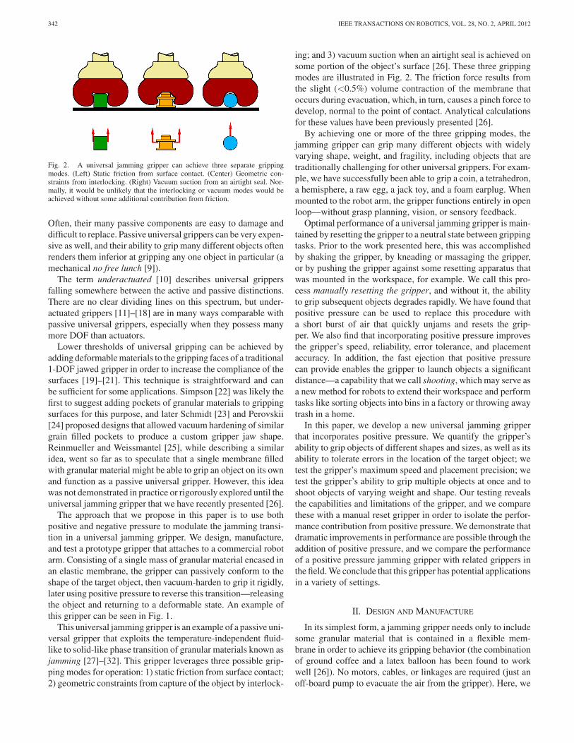
Fig. 2. A universal jamming gripper can achieve three separate grippingmodes. (Left) Static friction from surface contact. (Center) Geometric con-straints from interlocking. (Right) Vacuum suction from an airtight seal. Nor-mally, it would be unlikely that the interlocking or vacuum modes would beachieved without some additional contribution from friction.
Often, their many passive components are easy to damage anddifficult to replace. Passive universal grippers can be very expen-sive as well, and their ability to grip many different objects oftenrenders them inferior at gripping any one object in particular (amechanical no free lunch [9]).
The term underactuated [10] describes universal grippersfalling somewhere between the active and passive distinctions.There are no clear dividing lines on this spectrum, but under-actuated grippers [11]–[18] are in many ways comparable withpassive universal grippers, especially when they possess manymore DOF than actuators.
Lower thresholds of universal gripping can be achieved byadding deformable materials to the gripping faces of a traditional1-DOF jawed gripper in order to increase the compliance of thesurfaces [19]–[21]. This technique is straightforward and canbe sufficient for some applications. Simpson [22] was likely thefirst to suggest adding pockets of granular materials to grippingsurfaces for this purpose, and later Schmidt [23] and Perovskii[24] proposed designs that allowed vacuum hardening of similargrain filled pockets to produce a custom gripper jaw shape.Reinmueller and Weissmantel [25], while describing a similaridea, went so far as to speculate that a single membrane filledwith granular material might be able to grip an object on its ownand function as a passive universal gripper. However, this ideawas not demonstrated in practice or rigorously explored until theuniversal jamming gripper that we have recently presented [26].
The approach that we propose in this paper is to use bothpositive and negative pressure to modulate the jamming transi-tion in a universal jamming gripper. We design, manufacture,and test a prototype gripper that attaches to a commercial robotarm. Consisting of a single mass of granular material encased inan elastic membrane, the gripper can passively conform to theshape of the target object, then vacuum-harden to grip it rigidly,later using positive pressure to reverse this transition—releasingthe object and returning to a deformable state. An example ofthis gripper can be seen in Fig. 1.
This universal jamming gripper is an example of a passive uni-versal gripper that exploits the temperature-independent fluid-like to solid-like phase transition of granular materials known asjamming [27]–[32]. This gripper leverages three possible grip-ping modes for operation: 1) static friction from surface contact;2) geometric constraints from capture of the object by interlock-
ing; and 3) vacuum suction when an airtight seal is achieved onsome portion of the object’s surface [26]. These three grippingmodes are illustrated in Fig. 2. The friction force results fromthe slight (<0.5%) volume contraction of the membrane thatoccurs during evacuation, which, in turn, causes a pinch force todevelop, normal to the point of contact. Analytical calculationsfor these values have been previously presented [26].
By achieving one or more of the three gripping modes, thejamming gripper can grip many different objects with widelyvarying shape, weight, and fragility, including objects that aretraditionally challenging for other universal grippers. For exam-ple, we have successfully been able to grip a coin, a tetrahedron,a hemisphere, a raw egg, a jack toy, and a foam earplug. Whenmounted to the robot arm, the gripper functions entirely in openloop—without grasp planning, vision, or sensory feedback.
Optimal performance of a universal jamming gripper is main-tained by resetting the gripper to a neutral state between grippingtasks. Prior to the work presented here, this was accomplishedby shaking the gripper, by kneading or massaging the gripper,or by pushing the gripper against some resetting apparatus thatwas mounted in the workspace, for example. We call this pro-cess manually resetting the gripper, and without it, the abilityto grip subsequent objects degrades rapidly. We have found thatpositive pressure can be used to replace this procedure witha short burst of air that quickly unjams and resets the grip-per. We also find that incorporating positive pressure improvesthe gripper’s speed, reliability, error tolerance, and placementaccuracy. In addition, the fast ejection that positive pressurecan provide enables the gripper to launch objects a significantdistance—a capability that we call shooting, which may serve asa new method for robots to extend their workspace and performtasks like sorting objects into bins in a factory or throwing awaytrash in a home.
In this paper, we develop a new universal jamming gripperthat incorporates positive pressure. We quantify the gripper’sability to grip objects of different shapes and sizes, as well as itsability to tolerate errors in the location of the target object; wetest the gripper’s maximum speed and placement precision; wetest the gripper’s ability to grip multiple objects at once and toshoot objects of varying weight and shape. Our testing revealsthe capabilities and limitations of the gripper, and we comparethese with a manual reset gripper in order to isolate the perfor-mance contribution from positive pressure. We demonstrate thatdramatic improvements in performance are possible through theaddition of positive pressure, and we compare the performanceof a positive pressure jamming gripper with related grippers inthe field. We conclude that this gripper has potential applicationsin a variety of settings.
II. DESIGN AND MANUFACTURE
In its simplest form, a jamming gripper needs only to includesome granular material that is contained in a flexible mem-brane in order to achieve its gripping behavior (the combinationof ground coffee and a latex balloon has been found to workwell [26]). No motors, cables, or linkages are required (just anoff-board pump to evacuate the air from the gripper). Here, we
AMEND, JR. et al.: POSITIVE PRESSURE UNIVERSAL GRIPPER BASED ON THE JAMMING OF GRANULAR MATERIAL 343
Fig. 3. Assembly drawing of the positive pressure jamming gripper, includingcomponents: 1) base, 2) external collar, 3) balloon membrane, 4) coffee grains,5) air filter, 6) vacuum line port, and 7) high pressure port. The balloon ispinched between the base and the collar producing an airtight seal.
have developed a slightly more complex jamming gripper thatinterfaces with a commercial robot arm and includes a rigid col-lar surrounding the membrane, as well as a positive pressure portand an air filter. An assembly drawing of the design is shown inFig. 3.
One of the primary benefits of this design is its mechanicalsimplicity. The gripper is composed of just 12 components (theseven shown in Fig. 3 plus five machine screws). This con-tributes to its low cost and easy manufacturability. The collar isan important element of the design because it helps guide thegripper as it conforms to an object, increasing the surface con-tact on vertical faces of the object and maximizing the potentialfor the interlocking gripping mode. In this prototype, the collarand the base are both manufactured from 3-D printed plastic,which permits the intricate internal structures of the base.
The latex balloon membrane is pinched between the base andthe collar producing an airtight seal. The balloon membranethickness is 0.33 mm, and it is filled with ground coffee beansto a volume of 350 cm3 . At this volume, the gripper is full but themembrane is not significantly stretched; therefore, the grippercan be easily deformed in the unjammed state. The gripper isapproximately spherical, with a radius of 43 mm. The relativelylow density of ground coffee is advantageous because it can beused in larger quantities without weighing down the gripper orstraining the membrane in the way that a heavier material likesand would, for example.
III. PERFORMANCE
The jamming gripper was mounted on a commercial robotarm for testing. Positive pressure was provided at 620 kPa anda flow rate of 2.16 L/s. Vacuum was achieved with an off-board vacuum pump. A maximum vacuum flow rate of 0.25
Fig. 4. Hemispheres used in this test ranging from 5-mm radius to 38-mm ra-dius (left to right at top). Experimental setup showing key dimensions (bottom).The gripper picks the object at the pick location (P1 ) and then moves to placethe object at the place location (P2 ). The contact angle between the gripper andthe object is indicated by θ.
L/s was achieved with a pump rated for a maximum vacuum of25 microns. For gripping, the jamming transition was consideredcomplete when the pressure in the gripper dropped to −85 kPa,which took 1.1 s. The pressure in the gripper could also beneutralized with the atmosphere, and this state was used when-ever the gripper was pressed onto an object. Solenoid valvesthat are controlled by serial communication through the robotarm were used to modulate the pressure in the gripper. All testswere performed at 100% joint angle speed for the robot arm,which corresponds to approximately 240 mm/s linear speed ofthe gripper. When the manual reset gripper was tested, a 2 smassage was given between each gripping task to return it toa uniform neutral state. This setup was used throughout thefollowing subsections, except where otherwise noted.
A. Size and Reliability
The positive pressure jamming gripper was first evaluatedfor its reliability in gripping objects of varying size. All objectswere located at a position on a table that was hard-coded into therobot’s software (the pick position). The robot was instructed tomove to the pick position and press the jamming gripper ontoan object and to then actuate the gripper to induce the rigidstate. Next, the robot was instructed to move to a place position,release the vacuum, and apply a 0.1 s burst of positive pressureto eject the object. All tests were performed in open loop.
Spheres have been used as test objects for jamming grip-pers [26], but here, we have chosen to use hemispheres (ori-ented flat side down) so that the surface geometry of a spheretest would be preserved, but the height of the test objects wouldbe reduced. Wooden hemispheres ranging from 5 mm radius to38 mm radius were chosen, with a surface texture that was notsmooth enough to permit an airtight seal between the gripperand the hemisphere, therefore, not inducing the vacuum modeof gripping. Since the objects are hemispheres, it is also im-possible to achieve the interlocking gripping mode in this test.Each hemisphere was located in line with the central axis of the
344 IEEE TRANSACTIONS ON ROBOTICS, VOL. 28, NO. 2, APRIL 2012
Fig. 5. Results of gripping tests on hemispheres of varying radius using amanually reset gripper and a gripper reset with positive pressure. (a) Successrate for gripping objects of varying size. (b) Force that the gripper applies to anobject while deforming around it. (c) Contact angle that the gripper achieves.The horizontal dotted line in (c) indicates the critical 45◦ contact angle.
gripper so that the contact angle θ would be as consistent as pos-sible around the hemisphere. The test setup and the hemispheresthat are used for this test can be seen in Fig. 4. The dimensionsassociated with Fig. 4 were as follows: h1 = 48 mm, h2 =115 mm, h3 = 130 mm, and d = 200 mm.
Test results are shown in Fig. 5. The ordinate of each plot ispresented as a percentage of the gripper size in order to accountfor the scalability of the gripper [26]. Fig. 5 shows the perfor-mance of the new positive pressure gripper compared with amanually reset gripper. Plots of success rate, applied force, andcontact angle are shown. Success rate was determined over 30trials for each hemisphere and represents how reliably the grip-pers could grip hemispheres of varying size. Applied force isthe maximum force that a gripper applies to an object as it isdeformed around it. This force is measured with a scale that islocated beneath the test object. Contact angle is the maximumangle at which the gripper membrane and the object touch (asindicated by θ in Fig. 4). Contact angle was measured with thegripper pressed against the hemisphere and evacuated but be-fore the hemisphere was lifted. For the applied force and contactangle tests, ten trials were performed on each hemisphere. Forall three plots, the data points represent the average of the trials,and the error bars indicate the maximum and minimum mea-surements that are recorded during the test. Hemispheres weretested in random order for all tests.
It can be seen that for a gripper without positive pressure,the gripper’s success rate falls off sharply as the object radiusreaches about 65% of the gripper radius and falls to 0% forcontact angles near 45◦ (i.e., the critical angle for gripping tooccur [26]). No minimum object radius was observed in this test,although no hemispheres under 5 mm radius were tested becauseof their lack of availability in wood. We also see that the appliedforce increases with increasing object size, as more grains inside
the gripper need to be displaced around larger objects. Addingpositive pressure dramatically increases the success rate of thegripper by as much as 85% for some hemispheres by increasingcontact angle. Positive pressure also decreases the force that isapplied to the object by as much as 90%. These performanceincreases are most likely because of increased fluidization of thegranular material, which allows it to flow more easily aroundthe target object.
B. Error Tolerance
In this second test, the jamming gripper was evaluated fortolerance to errors in the location of the target object. The sametest setup from Fig. 4 was used, with hemispheres that are againemployed as test objects. In this test, however, the target objectwas located between 0 and 45 mm away from the pick loca-tion P1 , thus, causing the hemisphere to be unaligned with thegripper’s central axis. Results from this test are shown in Fig. 6.In Fig. 6(a), only results for the 25 mm radius hemisphere areshown, and 30 trials were performed for each data point. Wecan observe an increased error tolerance of up to 25% from theaddition of positive pressure. Fig. 6(b) illustrates a more gen-eral relationship between target object size, location error, andgripping success rate, and ten trials were performed for eachdata point shown, with errors ranging from 0 to 45 mm andhemispheres ranging from 5 to 38 mm radius.
Fig. 6(a) could be redrawn for any of the hemispheres thatwe tested, and a similar improvement for the positive pressuregripper would be shown. However, we find that the expression√
e2 + r2/R allows us to observe the error tolerance and re-liability of the gripper more generally. This expression can beunderstood as the Euclidean distance from the apex of the targetobject to the point where the gripper touches the table alongits central axis, compared with the radius of the gripper. It is asimple approximation of the total surface area the gripper willcontact (table plus target object), as it attempts to wrap aroundthe object to the critical contact angle, compared with the avail-able surface area of the gripper. An analytical calculation ofthese two surface areas would likely produce a more accuratequantity, but such a calculation is prohibitively difficult becauseof the deformation and stretching of the gripper membrane thatoccurs during the gripping process. We see in Fig. 6(b) that ourapproximation is sufficiently simple and accurate to collapse thedata and allow for quick estimations of gripping success rate. Inaddition, the close similarity between Figs. 5(a) and 6(b) shouldbe noted. This result is expected because
√e2 + r2/R reduces
to r/R for e = 0.The error tolerance that we observe for the jamming gripper
is very large considering its open-loop function. In Fig. 6(a),for example, we see that with the use of positive pressure, our43 mm radius gripper can successfully pick up a 25 mm radiushemisphere 100% of the time, even when the hemisphere is25 mm away from its target location. Furthermore, the ability ofjamming grippers to resist torques and off-axis forces has beenpreviously shown [26]. It is likely that this large error toler-ance would prove very useful for gripping tasks in unstructured
AMEND, JR. et al.: POSITIVE PRESSURE UNIVERSAL GRIPPER BASED ON THE JAMMING OF GRANULAR MATERIAL 345
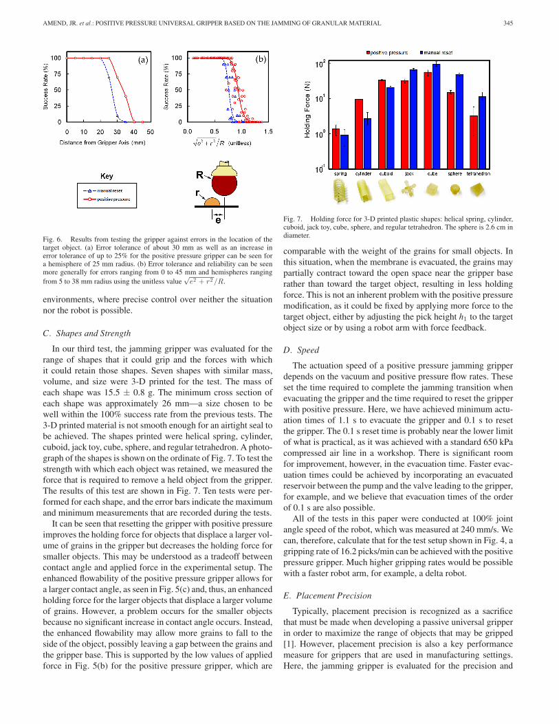
Fig. 6. Results from testing the gripper against errors in the location of thetarget object. (a) Error tolerance of about 30 mm as well as an increase inerror tolerance of up to 25% for the positive pressure gripper can be seen fora hemisphere of 25 mm radius. (b) Error tolerance and reliability can be seenmore generally for errors ranging from 0 to 45 mm and hemispheres rangingfrom 5 to 38 mm radius using the unitless value
√e2 + r2 /R.
environments, where precise control over neither the situationnor the robot is possible.
C. Shapes and Strength
In our third test, the jamming gripper was evaluated for therange of shapes that it could grip and the forces with whichit could retain those shapes. Seven shapes with similar mass,volume, and size were 3-D printed for the test. The mass ofeach shape was 15.5 ± 0.8 g. The minimum cross section ofeach shape was approximately 26 mm—a size chosen to bewell within the 100% success rate from the previous tests. The3-D printed material is not smooth enough for an airtight seal tobe achieved. The shapes printed were helical spring, cylinder,cuboid, jack toy, cube, sphere, and regular tetrahedron. A photo-graph of the shapes is shown on the ordinate of Fig. 7. To test thestrength with which each object was retained, we measured theforce that is required to remove a held object from the gripper.The results of this test are shown in Fig. 7. Ten tests were per-formed for each shape, and the error bars indicate the maximumand minimum measurements that are recorded during the tests.
It can be seen that resetting the gripper with positive pressureimproves the holding force for objects that displace a larger vol-ume of grains in the gripper but decreases the holding force forsmaller objects. This may be understood as a tradeoff betweencontact angle and applied force in the experimental setup. Theenhanced flowability of the positive pressure gripper allows fora larger contact angle, as seen in Fig. 5(c) and, thus, an enhancedholding force for the larger objects that displace a larger volumeof grains. However, a problem occurs for the smaller objectsbecause no significant increase in contact angle occurs. Instead,the enhanced flowability may allow more grains to fall to theside of the object, possibly leaving a gap between the grains andthe gripper base. This is supported by the low values of appliedforce in Fig. 5(b) for the positive pressure gripper, which are
Fig. 7. Holding force for 3-D printed plastic shapes: helical spring, cylinder,cuboid, jack toy, cube, sphere, and regular tetrahedron. The sphere is 2.6 cm indiameter.
comparable with the weight of the grains for small objects. Inthis situation, when the membrane is evacuated, the grains maypartially contract toward the open space near the gripper baserather than toward the target object, resulting in less holdingforce. This is not an inherent problem with the positive pressuremodification, as it could be fixed by applying more force to thetarget object, either by adjusting the pick height h1 to the targetobject size or by using a robot arm with force feedback.
D. Speed
The actuation speed of a positive pressure jamming gripperdepends on the vacuum and positive pressure flow rates. Theseset the time required to complete the jamming transition whenevacuating the gripper and the time required to reset the gripperwith positive pressure. Here, we have achieved minimum actu-ation times of 1.1 s to evacuate the gripper and 0.1 s to resetthe gripper. The 0.1 s reset time is probably near the lower limitof what is practical, as it was achieved with a standard 650 kPacompressed air line in a workshop. There is significant roomfor improvement, however, in the evacuation time. Faster evac-uation times could be achieved by incorporating an evacuatedreservoir between the pump and the valve leading to the gripper,for example, and we believe that evacuation times of the orderof 0.1 s are also possible.
All of the tests in this paper were conducted at 100% jointangle speed of the robot, which was measured at 240 mm/s. Wecan, therefore, calculate that for the test setup shown in Fig. 4, agripping rate of 16.2 picks/min can be achieved with the positivepressure gripper. Much higher gripping rates would be possiblewith a faster robot arm, for example, a delta robot.
E. Placement Precision
Typically, placement precision is recognized as a sacrificethat must be made when developing a passive universal gripperin order to maximize the range of objects that may be gripped[1]. However, placement precision is also a key performancemeasure for grippers that are used in manufacturing settings.Here, the jamming gripper is evaluated for the precision and
346 IEEE TRANSACTIONS ON ROBOTICS, VOL. 28, NO. 2, APRIL 2012
Fig. 8. Placement test results for the calibration of the robot arm, test ofthe positive pressure gripper, and test of the manually reset gripper. Ellipsesrepresent 95% confidence regions.
accuracy with which it can place objects, again using the sametest setup from Fig. 4 with slight modifications.
We first performed a calibration procedure to determine theprecision and accuracy of the robot arm itself. A pen was firmlymounted to the wrist of the robot, extending to approximatelythe same point at which a fully reset gripper would make con-tact with the table. A similar test procedure to Fig. 4 was thenexecuted, with the pen marking a fixed piece of paper at thepick and place positions P1 and P2 . With this setup, we wereable to determine the precision of the arm to be ±0.35 mm inthe worst case for 95% confidence, with an average offset of0.76 mm from the goal. This result is seven times larger thanthe manufacturers reported repeatability of ±0.05 mm, whichis likely due to the dynamic effects that are caused by movingthe robot arm at full speed.
Next, the pen was removed from the robot arm, and the gripperwas reattached. The robot arm was programmed to execute apick and place routine with the hemisphere, again using the testsetup from Fig. 4. Following placement of the hemisphere, wewere able to measure its deviation from its intended positionin the plane of the table. In this test, only the 18 mm radiushemisphere was used. This hemisphere is similar to the partsizes that are used in the shape test and is well within the 100%success rate range in the reliability test. The dimensions of Fig. 4were slightly modified for this test: When testing the positivepressure gripper, h2 was set at 88 mm, and When testing themanually reset gripper, h2 was set at 71 mm. The results areshown in Fig. 8.
We see from Fig. 8 that the positive pressure gripper placesthe hemisphere more accurately than the manually reset gripper,while the manually reset gripper is slightly more precise. Specif-ically, the average deviation of the positive pressure gripper is0.98 mm from the arm’s calibration center, with a precision of±1.00 mm in the worst case for 95% confidence, while the av-erage deviation for the manually reset gripper is 2.63 mm from
Fig. 9. Nine starting configurations that are used to test the jamming gripper’sability to grip multiple objects at once, shown from a top view.
the arm’s calibration center, with a precision of ±0.76 mm inthe worst case for 95% confidence.
The precision and accuracy in angular placement is compara-ble between the two grippers. Here, however, the manually resetgripper slightly was more accurate, while the positive pressuregripper was slightly more precise. The manually reset gripperrotated the hemisphere by 5.4◦ on average, ±3.4◦ for 95% con-fidence. The positive pressure gripper rotated the hemisphere by7.5◦ on average, ±1.8◦ for 95% confidence.
The placement accuracy improvement that we observe for thepositive pressure jamming gripper enables repeatable shootingbehavior presented later in Section III-G. It should be notedthat it is not strictly necessary to apply the positive pressureexactly at the moment of object release and that releasing theobject and resetting the gripper can be separated into distinctoperations. If the improved placement precision of the manualreset gripper is preferred, one could calibrate for the constantoffset in placement accuracy and then simply release the vacuumto drop the object and pressurize the gripper later to reset it.
F. Multiple Objects
A unique feature of jamming grippers is their ability to gripmultiple closely spaced objects simultaneously while maintain-ing their relative position and orientation. An example of thiswas shown in Fig. 1. To quantify this capability, we used twocuboids as test parts—each 13 × 13 × 45 mm. The gripper wasevaluated to pick these objects at the nine starting configurationsthat are shown in Fig. 9. We again implemented the test proce-dure from Fig. 4 with the same modifications that are specifiedin the placement precision test. For each test, the centroid of thecombined shape was located on the central axis of the gripper.The relative distance and angle between the two objects wasrecorded before and after the gripping operation.
We found that for relative distance, the manually reset grippertended to increase the separation between the objects by 0.8 mmon average, ±8.6 mm for 95% confidence, while the positivepressure gripper tended to increase the separation between theobjects by 7.7 mm on average, ±10.7 mm for 95% confidence.In terms of relative angle, the manually reset gripper changed
AMEND, JR. et al.: POSITIVE PRESSURE UNIVERSAL GRIPPER BASED ON THE JAMMING OF GRANULAR MATERIAL 347
the angle between the objects by 6.7◦ on average, ±20.5◦ for95% confidence, while the positive pressure gripper changedthe angle between the objects by 5.2◦ on average, ±22.2◦ for95% confidence.
This test shows a significant decrease in accuracy from theprevious test, where only one object was used. The increase inerror is likely the result of grips that occur away from the centralaxis of the gripper, where off-axis forces that tend to rotateor translate the gripped objects are more likely to occur. Theperformance of the positive pressure gripper is slightly inferiorto the manually reset gripper in this test, presumably becausethe rapid expansion of the membrane during the ejection ofthe object magnifies these off-axis forces, producing increasedrotations and translations of the gripped objects. This test revealsthe importance of centering objects on the gripper’s central axisin order to maximize placement accuracy.
The performance of both the positive pressure gripper and themanually reset gripper in this test indicates that they can be usedto grip multiple objects at once but that their ability to maintainthe relative distance and angle between the objects is only suit-able for tasks where a lower degree of accuracy is required. Forexample, this capability may be useful for transferring multiplealigned parts prior to a more accurate assembly operation.
G. Shooting
The fast ejection of objects by positively pressurizing thegripper enables the gripper to launch or shoot objects a signif-icant distance. Other grippers are typically unable to throw orshoot objects on their own, instead relying on the robot armto provide the momentum for throwing. To study the shootingcapability of the positive pressure jamming gripper, we devel-oped the test that is shown in Fig. 10. The gripper picks up theobject at a known location and then moves to the shooting loca-tion (h4 = 290 mm, φ = 45◦). A 0.1 s burst of pressurized air(2.16 L/s at 620 kPa) is then applied, and the shooting distance Lis measured. Seven 38 mm diameter spheres weighing between5 and 45 g were tested, along with the six additional shapes thatwere used in the holding force test. Results are shown in Fig. 10.
It can be seen that mass does not to have a significant in-fluence on the travel distance of ejected spheres. We can theninfer that the jamming gripper acts as a velocity source ratherthan a force source. This is useful because it means the angleφ is the relevant control parameter for shooting. It can also beseen that other objects tend not to travel as far as spheres. Thiscan be explained by the increased likelihood that the ejectionvelocity vector is not aligned with the center of these objectsand is instead partially lost in rotating the object. In addition,these nonspherical objects will likely experience increased at-mospheric drag. Furthermore, the four objects that travel theshortest distance have the sharpest corners. This could indicatethat a sharply bent membrane cannot relax as quickly and, thus,gives the object a lower initial velocity.
In general, for angle φ = 45◦ and h4 = 290 mm, objectsof varying size and weight can be ejected 602 mm ± 127 mmwith 95% confidence, which can be improved if the shape ofthe object is known. Precision in the perpendicular direction is
Fig. 10. Shooting test (top) results and (bottom) setup. The gripper shoots theobject from angle φ and height h4 so that distance L can be measured. Resultsshow the shooting distance for seven spheres of varying mass and six otherobjects with the same mass and varying shape.
±60 mm for 95% confidence. This is certainly too coarse forhigh-precision manufacturing tasks but could be useful for taskslike sorting objects into bins in a factory or throwing away trashin a home.
IV. RELATED GRIPPERS
To compare passive- and underactuated-type universal grip-pers with one another is a surprisingly difficult task. Grippersin this group often derive their utility from a unique grippingapproach, and this, in turn, necessitates an equally unique set oftests to demonstrate the gripper’s capabilities. No standard setof benchmark tests is followed in the literature. Further, manyof the references in this field focus primarily on the design,manufacturing, and control strategies that are implemented intheir particular gripper and, thus, provide minimal quantitativeperformance data. Some of the seemingly critical performanceparameters that we have presented here (especially placementprecision) are mostly absent from the related literature. Finally,most all of these grippers are singular prototypes that are pro-duced for research purposes and, therefore, cannot be obtainedfor further testing.
In this paper, we too have devised a customized set of teststhat we believe objectively and quantitatively reveal both thecapabilities and limitations of our proposed gripper. We are ableto compare the positive pressure jamming gripper with otherpassive- and underactuated-type universal grippers, as shownin Table I. Here, the DOF at Joints column indicates the num-ber of DOF at traditional joints, such as revolute or ball and
348 IEEE TRANSACTIONS ON ROBOTICS, VOL. 28, NO. 2, APRIL 2012
TABLE ICOMPARISON OF PASSIVE- AND UNDERACTUATED-TYPE UNIVERSAL GRIPPERS
socket joints. Flexural joints or members that can bend, stretch,or twist in multiple directions are included in the AdditionalCompliance column. The Object Size Range column specifiesthe range of objects that the gripper can pick up. This is normal-ized to the gripper size by dividing approximate object radius byapproximate gripper radius (r/R). If the gripper is a five-fingeredhand based closely on the dimensions of a human hand, thenwe replace otherwise unreported size ranges with ∼human. TheError Tolerance column is also normalized to the gripper sizeusing an object with approximately half the radius of the gripper.With this constant object size, error tolerance is the maximumtolerable error in object location divided by gripper radius (e/R).For grippers that are intended specifically for prosthetic uses, wereplace unreported values in the Error Tolerance and PlacementPrecision columns with NA, as these are typically the responsi-bility of the prosthesis operator rather than the hand itself. Anyvalues that are not specifically reported in the literature but thatcould be closely estimated were added to the table.
We have limited our survey to grippers that have two actu-ators or less and at least three times as many DOF as actua-tors. We believe this is the appropriate bound for comparisonbecause at the cutoff, it includes multifingered hands such asSARAH [16]–[18], which have some meaningful similarities inthe area of shape adaptation, but it excludes others like the Bar-rett Hand [33], which are more highly actuated and with which acomparison would have little utility. This survey is not exhaus-tive (particularly, in the area of prosthetics and five-fingeredhands) but serves to illustrate the trend of underreported andunknown performance metrics in the related literature. We hopethat the performance-centric approach of this paper will providesome new benchmarks for future work in the field.
From Table I, we can see that the positive pressure jamminggripper is the top performer in both error tolerance and place-ment precision, and its performance on the remaining tests isalso very good. There is no column in which the positive pres-sure jamming gripper is an obvious underperformer. These re-
sults further support the potential adoption of universal jamminggrippers for tasks where low complexity but high versatility arerequired.
V. CONCLUSION
In this paper, we have presented a passive universal jamminggripper that incorporates both positive and negative pressure.The design and manufacture of a prototype gripper were de-scribed, and this prototype was evaluated against five metricsthat revealed its capabilities for real-world applications. Thepositive pressure gripper proved capable at gripping objects ofdifferent size and shape, and when compared with a versionwithout positive pressure, it showed an increase in reliability ofup to 85% and an increase in error tolerance of up to 25%. Thepositive pressure gripper also applied up to 90% less force ontarget objects, demonstrated an increase in placement accuracy,and was able to extend its workspace up to 600 mm by shoot-ing objects. This ability to manipulate objects by shooting maybe useful for tasks like sorting objects into bins in a factory orthrowing away trash in a home.
With this jamming gripper, objects of very different shape,weight, and fragility can be gripped, and multiple objects canbe gripped at once while maintaining their relative distance andorientation. This diversity of abilities may make the gripper wellsuited for use in unstructured domains ranging from militaryenvironments to the home and, perhaps, for variable industrialtasks, such as food handling. The gripper’s airtight constructionalso provides the potential for use in wet or volatile environmentsand permits easy cleaning. Its thermal limits are determinedonly by the latex rubber membrane, because of the temperatureindependence of the jamming phase transition; therefore, usein high- or low-temperature environments may also be possiblewith a modified design. Furthermore, the soft malleable statethat the gripper assumes between gripping tasks could providean improvement in safety when deployed in close proximitywith humans, as in the home, for example.
AMEND, JR. et al.: POSITIVE PRESSURE UNIVERSAL GRIPPER BASED ON THE JAMMING OF GRANULAR MATERIAL 349
The durability of a single latex membrane could be a concern,and we believe that future work in this area will lead to improvedmembrane materials. It should be noted, however, that through-out our several hundreds of tests conducted for this paper, thelatex membrane never failed and showed no visible signs ofwear.
We have demonstrated a jamming-based gripper with a num-ber of unique capabilities and adept performance. However, thegripper that is presented here is still a fairly early prototype. Webelieve that significant performance gains are possible and thatfurther research will serve to optimize the gripper membrane,jamming material, and overall design to produce a gripper thatfar surpasses the capabilities and performance that are demon-strated here.
REFERENCES
[1] D. T. Pham and S. H. Yeo, “Strategies for gripper design and selection inrobotic assembly,” Int. J. Prod. Res., vol. 29, pp. 303–316, Feb. 1991.
[2] A. Bicci and V. Kumar, “Robotic grasping and contact: A review,” inProc. IEEE Int. Conf. Robot. Autom., Apr., 2000, pp. 348–353.
[3] A. T. Miller, S. Knoop, P. K. Allen, and H. I. Christensen, “Automaticgrasp planning using shape primitives,” in Proc. IEEE Int. Conf. Robot.Autom., Sep., 2003, pp. 1824–1829.
[4] K. B. Shimoga, “Robot grasp synthesis algorithms: A survey,” Int. J.Robot. Res., vol. 15, pp. 230–266, Jun. 1996.
[5] A. Saxena, J. Driemeyer, and A. Y. Ng, “Robotic grasping of novel objectsusing vision,” Int. J. Robot. Res., vol. 27, pp. 157–173, Feb. 2008.
[6] P. B. Scott, “The ‘Omnigripper’: A form of robot universal gripper,”Robotica, vol. 3, pp. 153–158, Sep. 1985.
[7] R. Tella, J. Birk, and R. Kelley, “A contour-adapting vacuum gripper,” inRobot Grippers, D. T. Pham and W. B. Heginbotham, Eds. New York:Springer-Verlag, 1986, pp. 86–100.
[8] F. Ilievski, A. D. Mazzeo., R. F. Shepherd, X. Chen, and G. M. Whitesides,“Soft robotics for chemists,” Angewandte Chemie International Edition,vol. 50, pp. 1890–1895, Feb. 2011.
[9] D. H. Wolpert and W. G. Macready, “No free lunch theorems for opti-mization,” IEEE Trans. Evol. Comput., vol. 1, no. 1, pp. 67–82, Apr.1997.
[10] L. Birglen, T. Laliberte, and C. Gosselin, Underactuated Robotic Hands.Berlin, Germany: Springer-Verlag, 2008.
[11] S. Hirose and Y. Umetani, “The development of soft gripper for the ver-satile robot hand,” Mech. Mach. Theory, vol. 13, pp. 351–359, 1978.
[12] S. Hirose, “Connected differential mechanism and its applications,” inRobot Grippers, D. T. Pham and W. B. Heginbotham, Eds. New York:Springer-Verlag, 1986, pp. 141–153.
[13] A. M. Dollar and R. D. Howe, “A robust compliant grasper via shapedeposition manufacturing,” IEEE/ASME Trans. Mechatron., vol. 11, no. 2,pp. 154–161, Apr. 2006.
[14] A. M. Dollar and R. D. Howe, “Simple, robust autonomous grasping inunstructured environments,” in Proc. IEEE Int. Conf. Robot. Autom., Apr.2007, pp. 4693–4700.
[15] A. M. Dollar and R. D. Howe, “The SDM Hand as a prosthetic terminaldevice: A feasibility study,” in Proc. IEEE Int. Conf. Rehabil. Robot.,Jun., 2007, pp. 978–983.
[16] T. Laliberte and C. Gosselin, “Underactuation in space robotic hands,” inProc. 6th Int. Symp. Artif. Intell., Robot., Autom. Space, Jun. 2001.
[17] T. Laliberte, L. Birglen, and C. Gosselin, “Underactuation in robotic grasp-ing hands,” Mach. Intell. Robot. Control, vol. 4, pp. 1–11, Sep. 2002.
[18] B. Rubinger, M. Brousseau, J. Lymer, C. Gosselin, T. Laliberte, andJ. C. Piedbœuf, “A novel robotic hand-SARAH for operations on theInternational Space Station,” in Proc. 7th Workshop Adv. Space Technol.Robot. Autom., Nov. 2002.
[19] H. J. Warnecke and I. Schmidt, “Flexible gripper for handling systems:Design possibilities and experiences,” Int. J. Prod. Res., vol. 18, pp. 525–537, Sep./Oct. 1980.
[20] P. K. Wright and M. R. Cutkosky, “Design of grippers,” in Handbook ofIndustrial Robotics, S. F. Nof, Ed. New York: Wiley, 1985, pp. 91–111.
[21] H. Choi and M. Koc, “Design and feasibility tests of a flexible gripperbased on inflatable rubber pockets,” Int. J. Mach. Tools Manuf., vol. 46,pp. 1350–1361, Oct. 2006.
[22] D. C. Simpson, “Gripping surfaces for artificial hands,” Hand, vol. 3,pp. 12–14, Feb. 1971.
[23] I. Schmidt, “Flexible moulding jaws for grippers,” Ind. Robot, vol. 5,pp. 24–26, Mar. 1978.
[24] A. P. Perovskii, “Universal grippers for industrial robots,” Russian Eng.J., vol. 60, pp. 9–11, Aug. 1980.
[25] T. Reinmuller and H. Weissmantel, “A shape adaptive gripper finger forrobots,” Proc. Int. Symp. Ind. Robots, pp. 241–250, Apr. 1988.
[26] E. Brown, N. Rodenberg, J. Amend, A. Mozeika, E. Steltz, M. Zakin,H. Lipson, and H. Jaeger, “Universal robotic gripper based on the jam-ming of granular material,” Proc. Nat. Acad. Sci., Nov. 2010, vol. 107,pp. 18809–18814.
[27] T. S. Majmudar, M. Sperl, S. Luding, and R. P. Behringer, “Jammingtransition in granular systems,” Phys. Rev. Lett., vol. 98, pp. 058001–058004, Feb. 2007.
[28] A. J. Liu and S. R. Nagel, “Jamming is not just cool any more,” Nature,vol. 396, pp. 21–22, Nov. 1998.
[29] M. E. Cates, J. P. Wittmer, J. P. Bouchaud, and P. Claudin, “Jamming, forcechains, and fragile matter,” Phys. Rev. Lett., vol. 81, pp. 1841–1844, Aug.1998.
[30] A. J. Liu and S. R. Nagel, Jamming and Rheology: Constrained Dynam-ics on Microscopic and Macroscopic Scales. London, U.K.: Taylor &Francis, 2001.
[31] C. S. O’Hern, L. E. Silbert, A. J. Liu, and S. R. Nagel, “Jamming at zerotemperature and zero applied stress: The epitome of disorder,” Phys. Rev.E, vol. 68, pp. 011306–011336, Jul. 2003.
[32] E. I. Corwin, H. M. Jaeger, and S. R. Nagel, “Structural signature ofjamming in granular media,” Nature, vol. 435, pp. 1075–1078, Apr.2005.
[33] W. Townsend, “The BarrettHand grasper—Programmably flexible parthandling and assembly,” Ind. Robot, vol. 27, pp. 181–188, 2000.
[34] M. Kaneko, M. Higashimori, R. Takenaka, A. Namiki, and M. Ishikawa,“The 100 G capturing robot—Too fast to see,” IEEE/ASME Trans. Mecha-tronics, vol. 8, no. 1, pp. 37–44, Mar. 2003.
[35] M. Higashimori, M. Kaneko, A. Namiki, and M. Ishikawa, “Design of the100G capturing robot based on dynamic preshaping,” Int. J. Robot. Res.,vol. 24, pp. 743–753, Sep. 2005.
[36] R. Tella, J. R. Birk, and R. B. Kelley, “General purpose hands for bin-picking robots,” IEEE Trans. Syst., Man, Cybern., vol. SMC-12, no. 6,pp. 828–837, Nov./Dec. 1982.
[37] Y. Kamikawa and T. Maeno, “Underactuated five-finger prosthetic handinspired by grasping force distribution of humans,” in Proc. IEEE/RSJ Int.Conf. Intell. Robots Syst., Sep. 2008, pp. 717–722.
[38] C. Gosselin, F. Pelletier, and T. Laliberte, “An anthropomorphic underac-tuated robotic hand with 15 DOFs and a single actuator,” in Proc. IEEEInt. Conf. Robot. Autom., May 2008, pp. 749–754.
[39] B. Massa, S. Roccella, M. C. Carrozza, and P. Dario, “Design and devel-opment of an underactuated prosthetic hand,” in Proc. IEEE Int. Conf.Robot. Autom., May 2002, vol. 4, pp. 3374–3379.
[40] M. C. Carrozza, F. Vecchi, F. Sebastiani, G. Cappiello, S. Roccella,M. Zecca, R. Lazzarini, and P. Dario, “Experimental analysis of an in-novative prosthetic hand with proprioceptive sensors,” in Proc. IEEE Int.Conf. Robot. Autom., Sep. 2003, vol. 2, pp. 2230–2235.
[41] M. C. Carrozza, C. Suppo, F. Sebastiani, B. Massa, F. Vecchi, R. Lazzarini,M. R. Cutkosky, and P. Dario, “The SPRING hand: Development of a self-adaptive prosthesis for restoring natural grasping,” Auton. Robots, vol. 16,pp. 125–141, Mar. 2004.
[42] N. Dechev, W. L. Cleghorn, and S. Naumann, “Multiple finger, passiveadaptive grasp prosthetic hand,” Mech. Mach. Theory, vol. 36, pp. 1157–1173, Oct. 2001.
[43] N. Fukaya, S. Toyama, T. Asfour, and R. Dillmann, “Design of theTUAT/Karlsruhe humanoid hand,” in Proc. IEEE/RSJ Int. Conf. Intell.Robots Syst., Oct./Nov. 2000, vol. 3, pp. 1754–1759.
John R. Amend, Jr. (S’10) received the B.S. degreein mechanical engineering from the State Universityof New York at Buffalo (SUNY Buffalo) in 2008. Heis currently working toward the Ph.D. degree with theCreative Machines Lab, Cornell University, Ithaca,NY.
In 2007 and 2008, he was involved in researchactivities with the Automation Robotics and Mecha-tronics Laboratory, and the Design of Open Engi-neering Systems Laboratory, both at SUNY Buffalo.His current research interests include using controlled
granular jamming for physically adaptive robots.Mr. Amend is a Student Member of the American Society of Mechanical
Engineers and the American Society for Engineering Education, as well as aNational Science Foundation Graduate Research Fellowship recipient.
350 IEEE TRANSACTIONS ON ROBOTICS, VOL. 28, NO. 2, APRIL 2012
Eric Brown was born in Wilmington, DE. He re-ceived the B.S. degree in physics from Harvey MuddCollege, Claremont, CA, in 2002 and the Ph.D. de-gree in physics from the University of California,Santa Barbara, in 2007.
He is currently an Assistant Professor with theSchool of Natural Sciences, University of Califor-nia, Merced. He was a Postdoctoral Scholar with theJames Franck Institute, The University of Chicago,Chicago, IL. His current research interests includerheology, granular materials, and turbulence.
Dr. Brown is a member of the American Physical Society and the Society ofRheology.
Nicholas Rodenberg received the B.A. degree inphysics from the University of Chicago, Chicago,IL, in 2010.
He is currently a Robotic Technician for the LS3Program with Boston Dynamics, Waltham, MA. Heperformed research as an undergraduate with the Uni-versity of Chicago under Dr. H. Jaeger in the fieldsof granular behavior and materials science. He spentfive years as a Helicopter Mechanic in the UnitedStates Marine Corps.
Heinrich M. Jaeger received the Vordiplom de-gree in physics from the University of Kiel, Kiel,Germany, in 1979 and the Ph.D. degree in physicsfrom the University of Minnesota, Minneapolis, in1987.
He is currently the William J. Friedman and AliciaTownsend Professor of physics with the University ofChicago, Chicago, IL. On the faculty with the Uni-versity of Chicago since 1991, he has been a Directorof the Chicago Materials Research Science and Engi-neering Center and of the James Franck Institute. His
current research interests focus on using particle assemblies, from nanoparticlesto macroscopic granular matter, for the design of functional materials.
Hod Lipson (M’98) received the B.Sc. degree in me-chanical engineering and the Ph.D. degree in me-chanical engineering in computer-aided design andartificial intelligence in design from the Technion–Israel Institute of Technology, Haifa, Israel, in 1989and 1998, respectively.
He is currently an Associate Professor with theSibley School of Mechanical and Aerospace Engi-neering and Computing and Information Science,Cornell University, Ithaca, NY. He was a Postdoc-toral Researcher with the Department of Computer
Science, Brandeis University, Waltham, MA. He was a Lecturer with the De-partment of Mechanical Engineering, Massachusetts Institute of Technology,Cambridge, where he was involved in conducting research in design automa-tion. His current research interests include computational methods to synthesizecomplex systems out of elementary building blocks and the application of suchmethods to design automation and their implication toward understanding theevolution of complexity in nature and in engineering.