43
IMPLEMENTATION OF AN IEEE 802.11A TRANSMITTER IN VHDL FOR ALTERA STRATIX II FPGA Examensarbete utfört i Elektroniksystem av Johannes Brännström LiTH-ISY-EX--06/3920--SE Linköping 2006
IMPLEMENTATION OF AN IEEE
802.11A TRANSMITTER IN VHDL FOR
ALTERA STRATIX II FPGA
Examensarbete utfört i Elektroniksystem
av
Johannes Brännström
LiTH-ISY-EX--06/3920--SE
Linköping 2006

IMPLEMENTATION OF AN IEEE
802.11A TRANSMITTER IN VHDL FOR
ALTERA STRATIX II FPGA
Examensarbete utfört i Elektroniksystem
vid Linköpings Tekniska Högskola
av
Johannes Brännström
LiTH-ISY-EX--06/3920--SE
Supervisor: Jonas Carlsson
Examiner: Kent Palmkvist
Linköping, 29 August 2006.


Presentationsdatum
2006-08-24Publiceringsdatum (elektronisk version)
2006-06-29
Institution och avdelning
Institutionen för systemteknikAvdeldningen för elektronik system58183 Linköping
URL för elektronisk versionhttp://urn.kb.se/resolve?urn=urn:nbn:se:liu:diva-3920
Publikationens titelImplementation of an IEEE 802.11a transmitter in VHDL for Altera Stratix II FPGA
FörfattareJohannnes Brännström
Sammanfattning
The fast growth of wireless local area networks today has opened up a whole new market for wireless solutions. Released in1999, the IEEE 802.11a is a standard for high-speed wireless data transfer that much of modern Wireless Local AreaNetwork technology is based on.
This project has been about implementing the transmitter part of the 802.11a physical layer in VHDL to run on the AlteraStratix II FPGA. Special consideration was taken to divide the system into parts based on sample rate. This report contains abrief introduction to Orthogonal Frequency Division Multiplexing and to the IEEE 802.11a physical layer as well as adescription of the implemented system.
Antal sidor: 34
Nyckelord
OFDM, WLAN, 802.11a, VHDL, FPGA

ABSTRACT
The fast growth of wireless local area networks today has opened up a wholenew market for wireless solutions. Released in 1999, the IEEE 802.11a is astandard for high-speed wireless data transfer that much of modern WirelessLocal Area Network technology is based on.
This project has been about implementing the transmitter part of the 802.11aphysical layer in VHDL to run on the Altera Stratix II FPGA. Special consid-eration was taken to divide the system into parts based on sample rate. Thisreport contains a brief introduction to Orthogonal Frequency Division Multi-plexing and to the IEEE 802.11a physical layer as well as a description of theimplemented system.
Keywords: OFDM, WLAN, 802.11a, VHDL, FPGA


ACKNOWLEDGEMENTS
First I want to thank my supervisor Jonas Carlsson, for invaluable supportduring the process.I would also like to thank all the people working at Electronics systems, espe-cially the other undergraduate students working in ES Fo-lab. In particular, Iwould like to thank Kaj Rosengren for being my opponent and for proofread-ing this report.I also want to thank my family for their constant support.


ix
TABLE OF CONTENTS
1 Introduction 11.1 Background . . . . . . . . . . . . . . . . . . . . . . . . . . . . . . 11.2 Goal . . . . . . . . . . . . . . . . . . . . . . . . . . . . . . . . . . . . 1
2 Theory 32.1 Orthogonal Frequency Division Multiplexing. . . . 32.2 Wireless LAN . . . . . . . . . . . . . . . . . . . . . . . . . . . . 4
2.2.1 Transmitter. . . . . . . . . . . . . . . . . . . . . . . . . . . . 52.2.2 Coding . . . . . . . . . . . . . . . . . . . . . . . . . . . . . . . 62.2.3 Interleaving . . . . . . . . . . . . . . . . . . . . . . . . . . . 72.2.4 Mapping. . . . . . . . . . . . . . . . . . . . . . . . . . . . . . 92.2.5 IFFT . . . . . . . . . . . . . . . . . . . . . . . . . . . . . . . . 102.2.6 Cyclic Prefix . . . . . . . . . . . . . . . . . . . . . . . . . 112.2.7 Windowing . . . . . . . . . . . . . . . . . . . . . . . . . . 13
3 Design Environment 153.1 Design Flow . . . . . . . . . . . . . . . . . . . . . . . . . . . . . 153.2 VHDL . . . . . . . . . . . . . . . . . . . . . . . . . . . . . . . . . 153.3 Field-Programmable Gate Array . . . . . . . . . . . . . 163.4 Design Tools . . . . . . . . . . . . . . . . . . . . . . . . . . . . 16
3.4.1 Emacs. . . . . . . . . . . . . . . . . . . . . . . . . . . . . . . 163.4.2 Matlab . . . . . . . . . . . . . . . . . . . . . . . . . . . . . . 163.4.3 ModelSim . . . . . . . . . . . . . . . . . . . . . . . . . . . 173.4.4 Precision RTL Synthesis . . . . . . . . . . . . . . . . 173.4.5 Quartus II . . . . . . . . . . . . . . . . . . . . . . . . . . . . 17
4 Implementation 194.1 Transmitter . . . . . . . . . . . . . . . . . . . . . . . . . . . . . . 19
4.1.1 Preamble . . . . . . . . . . . . . . . . . . . . . . . . . . . . 204.1.2 FEC coder . . . . . . . . . . . . . . . . . . . . . . . . . . . 204.1.3 Interleaving . . . . . . . . . . . . . . . . . . . . . . . . . . 214.1.4 Mapping. . . . . . . . . . . . . . . . . . . . . . . . . . . . . 224.1.5 Pilot-insertion . . . . . . . . . . . . . . . . . . . . . . . . 244.1.6 Rotation . . . . . . . . . . . . . . . . . . . . . . . . . . . . . 244.1.7 Zero-insertion . . . . . . . . . . . . . . . . . . . . . . . . 25

x
4.1.8 IFFT . . . . . . . . . . . . . . . . . . . . . . . . . . . . . . . . 254.1.9 Shifting . . . . . . . . . . . . . . . . . . . . . . . . . . . . . 254.1.10 Cyclic prefix . . . . . . . . . . . . . . . . . . . . . . . . . 264.1.11 Windowing . . . . . . . . . . . . . . . . . . . . . . . . . . 26
5 Testing 275.1 Test Setup. . . . . . . . . . . . . . . . . . . . . . . . . . . . . . . 27
5.1.1 Simulation . . . . . . . . . . . . . . . . . . . . . . . . . . . 275.1.2 Hardware . . . . . . . . . . . . . . . . . . . . . . . . . . . . 28
5.2 Test result. . . . . . . . . . . . . . . . . . . . . . . . . . . . . . . 28
6 Conclusion 296.1 Summary . . . . . . . . . . . . . . . . . . . . . . . . . . . . . . . 296.2 Result . . . . . . . . . . . . . . . . . . . . . . . . . . . . . . . . . . 296.3 Future Work . . . . . . . . . . . . . . . . . . . . . . . . . . . . . 30
References 31

1
1
INTRODUCTION
The fast growth of wireless local area networks today has opened up a wholenew market for wireless solutions. Released in 1999, the IEEE 802.11a [1] isa standard for high-speed wireless data transfer that much of modern Wire-less Local Area Network (WLAN) technology is based on.
To shorten developement cycles of new products fast prototyping is essential.By using FPGAs and industry-standard developement software for prototyp-ing, costs and time-to-market can be reduced.
1.1 BACKGROUND
This undergraduate thesis has been carried out at the Division of ElectronicsSystems at Linköpings University. The research and education at the divisionof Electronics Systems are focused on methodologies for efficient design andimplementation of digital and analog signal processing as well as communi-cation systems. One of the research topics of the division is design and imple-mentation of systems using the GALS approach [6]. The purpose of thisundergraduate thesis is to create a globally synchronous system, similar instructure to a GALS system, to facilitate comparison of the metodologies.
1.2 GOAL
This project has been about implementing the transmitter part of the 802.11aphysical layer in VHDL to run on the Altera Stratix II FPGA [2]. The imple-mentation has been done using a Simulink [3] model by Jonas Carlsson [4]for reference, design software such as Quartus II from Altera and ModelSimand Precision RTL Synthesis from Mentor Graphics [5]. While most of the

2 Implementation of an IEEE 802.11a transmitter in VHDL for Altera Stratix II FPGA
code has been written using Emacs, some has been generated by MATLABscripts.
3
2
THEORY
This chapter is to be seen as a short introduction to the underlying theory andconcepts required to understand the implementation. To fully understand theconcepts the reader is advised to look to other sources, [7, 8] for example.The source of some illustrations is the IEEE 802.11a document and aremarked by this reference [1].
2.1 ORTHOGONAL FREQUENCY DIVISION MULTI-
PLEXING
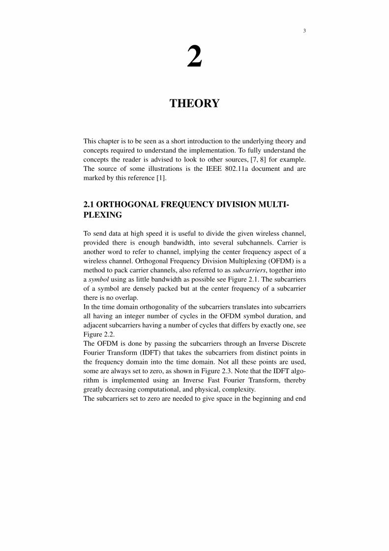
To send data at high speed it is useful to divide the given wireless channel,provided there is enough bandwidth, into several subchannels. Carrier isanother word to refer to channel, implying the center frequency aspect of awireless channel. Orthogonal Frequency Division Multiplexing (OFDM) is amethod to pack carrier channels, also referred to as subcarriers, together intoa symbol using as little bandwidth as possible see Figure 2.1. The subcarriersof a symbol are densely packed but at the center frequency of a subcarrierthere is no overlap.In the time domain orthogonality of the subcarriers translates into subcarriersall having an integer number of cycles in the OFDM symbol duration, andadjacent subcarriers having a number of cycles that differs by exactly one, seeFigure 2.2.The OFDM is done by passing the subcarriers through an Inverse DiscreteFourier Transform (IDFT) that takes the subcarriers from distinct points inthe frequency domain into the time domain. Not all these points are used,some are always set to zero, as shown in Figure 2.3. Note that the IDFT algo-rithm is implemented using an Inverse Fast Fourier Transform, therebygreatly decreasing computational, and physical, complexity.The subcarriers set to zero are needed to give space in the beginning and end
4 Implementation of an IEEE 802.11a transmitter in VHDL for Altera Stratix II FPGA
of the frequency space because of filtering needed after Digital to AnalogConversion (DAC). With little space the filter would need very steep edgesand therefore become complex, see Figure 2.4.
2.2 WIRELESS LAN
Sending data over a wireless channel is simple. Making the informationretreiveable is not, and yet more difficult is to do this using limited band-width. WLAN is designed to provide high speed data transfer within a rela-tively short distance of the access point, ideally in a building or a room where
Figure 2.1: Orthogonal Frequency Division Multiplexing.
Figure 2.2: Subcarriers within an OFDM symbol.
f
t

Chapter 2 – Theory 5
it can also be assumed that sender and receiver are not moving very fast rela-tive to each other. The main things here are the coding, interleaving, mappingand the IFFT/FFT. None are particulary new but they make up a powerfulwhole.
2.2.1 TRANSMITTER
Here are descriptions of the different stages of the sending system. It is essen-tially a pipeline taking bits as input and delivering analog waveforms as out-put, see Figure 2.5.
Figure 2.3: Inverse Fast Fourier Transform.[1]
Figure 2.4: Frequency view of a symbol.
Figure 2.5: Flowchart of the transmitter.
-26 to -11 to 26 Filter after the DAC.
-26 26-32 32
FFT period = 64 samples
f
Coding Interleaving Mapping IFFT CyclicPrefix Windowing RF MAC

6 Implementation of an IEEE 802.11a transmitter in VHDL for Altera Stratix II FPGA
The output, grouped in frames, consists of two parts, preamble and data asshown in Figure 2.6. The first data symbol, also referred to as the signal field,contains parameters such as the data rate of the frame, the intitial state used inthe scrambler and the length of the frame in number of data symbols. Theframe can have from 1 to 4096 data symbols. The preamble part is there tocalibrate the receiver because we want to send time and frequency sensitivedata under conditions that can vary. The preamble is always the same and hastwo parts, short and long training symbols. The short symbols have a shortperiod and repeat every 16 subcarriers while the long ones repeat every 64.The short training symbols (t1 to t10) are used to give a rough estimate of thetime and frequency conditions while the long (T1 to T2) provide finer tuning.
The preamble imposes limits on how much the time and frequency offsetsmay change. A user who is constantly changing his speed relative to theaccesspoint while communicating a frame could get strange results, the cali-brated offsets are not valid if the changes in speed are too large. The receivercan compensate constant phase offsets, created by moving at constant speed,by comparing the preamble. However, there is a limit. At the lowest data rate,moving at a speed that results in a phase offset of more than 90 degrees willcause the receiver to fail. Together this means moving is bad for the data rate.
2.2.2 CODING
The data is encoded in several steps, the first being the scrambing, seeFigure 2.7. The scrambler adds noise to the data in a pseudo-randomsequence determined by an initial state. The initial state is sent to the receiverembedded in the first data symbol, also referred to as the signal field, seeFigure 2.6. The scrambler reduces the risk of long sequences of ones orzeroes being passed on to later stages.
The second is the convolutional encoder, see Figure 2.8. This unit spreads thedata in one bit, over several consecutive bits and adds redundancy to allow
Figure 2.6: A frame consists of preamble and data symbols.
Short training symbols Long training symbols
CP2 T1 T2 CP CPSIGNAL DATA1
t10t5t1
160 samples 160 80 80
. . .CP DATA2
80
Data symbols

Chapter 2 – Theory 7
Forward Error Correction (FEC) in the receiver [7, 8]. This way a bit-errormay be recovered based only on previously received bits.
The third is puncturing. To increase the transmission throughput, redundan-cybits are taken away from the datastream according to a specified schemeselected by the coding rate and inserted in the receiver see Figure 2.9. Therate of data bits per bits transferred can be 1/2, that is one data bit per twobits, 2/3 or 3/4.
2.2.3 INTERLEAVING
To help ensure that a sequence of errors in the reception does not cause errorsin the convolutional decoder, using the Viterbi algorithm [7, 8], this unit
Figure 2.7: Scrambler.[1]
Figure 2.8: Convolutional encoder.[1]

8 Implementation of an IEEE 802.11a transmitter in VHDL for Altera Stratix II FPGA
Figure 2.9: Puncturing.[1]

Chapter 2 – Theory 9
changes the sequence of the bits coming from the puncturing. There are twopermutations; the first so that adjacent bits are mapped to non-adjacent sub-carriers, the second so that adjacent coded bits are mapped alternately ontoless and more significant bits. This way adjacent data is spread over the wholesymbol and thereby makes more efficient use of the convolutional encoder,see Figure 2.10.
2.2.4 MAPPING
To make proper use of the IFFT in the next section, we feed data in the formof complex numbers. Each complex number represents a subcarrier. Themapper essentially maps bits or groups of bits onto complex numbers basedon the data rate, see Table 2.1.
In Figure 2.11 combinations of bits are mapped to complex numbers. Themodulation is one of Binary Phase Shift Keying (BPSK), Quadrature PSK
Figure 2.10: Schematic of the first interleaver permutation.
Table 2.1: Data rates and their modulation
Data Rate(Mbits/s)
ModulationCoding
rate
Coded bitsper
subcarrier
Coded bitsper OFDM
symbol
Data bitsper OFDM
symbol
6 BPSK 1/2 1 48 24
9 BPSK 3/4 1 48 36
12 QPSK 1/2 2 96 48
18 QPSK 3/4 2 96 72
24 16-QAM 1/2 4 192 96
36 16-QAM 3/4 4 192 144
48 64-QAM 2/3 6 288 192
54 64-QAM 3/4 6 288 216
SUBCARRIER:1 2 3 4

10 Implementation of an IEEE 802.11a transmitter in VHDL for Altera Stratix II FPGA
(QPSK), 16-Quadrature Amplitude Modulation (QAM) or 64-QAM. PSKuses only phase to separate points, QAM also uses amplitude, seen as the dis-tance to (0,0). QAM is useful to more evenly distribute points as more data issent per subcarrier, but increases interference. 64-QAM is similar to 16-QAMbut has a higher density of points.
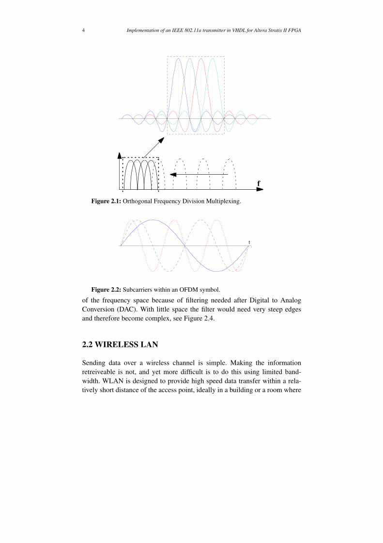
An error in the reception of a complex value at 16-QAM would cause error inup to 4 bits. However, because the constellation is gray-coded the receivedsignal would have to be completely different from the original one to give thefull 4 bit error. In common cases of error there are several complex values thatare slightly off, perhaps generating errors in one bit each. Such errors may berecovered if many bits are coded per subcarrier and the coding rate is low, at3/4 it may be difficult but at 1/2 it is much easier. However, more dense con-stellations make errors in more than one bit more likely. In Figure 2.12 themeasured is slightly off.
2.2.5 IFFT
In the 802.11a standard, the OFDM is implemented using an Inverse FastFourier Transform (IFFT) as IDFT see section 2.1. The IFFT transforms thesubcarriers from the frequency domain into the time domain. Since a 64-pointIFFT is used 64 samples designate the OFDM symbol duration, or period.
Figure 2.11: Rate dependent constellation mapping.[1]
1110 = k16 * (3 + 3i)
Chapter 2 – Theory 11
The corresponding time, TFFT, is . The bandwidth of the symbol is lim-ited to 20 MHz [1].
2.2.6 CYCLIC PREFIX
If a reflection of an OFDM symbol is arriving at a certain delay or offset, theOFDM will suffer from Inter Carrier Interference (ICI). For the OFDM toretain orthogonality, the FFT in the receiver needs an OFDM symbol periodof the subcarriers which is free from the phase shifts that occur at the end ofeach OFDM symbol as a result of the modulation. To address this, the OFDMsymbol is extended by copying the last part to the front. Now a reflectionmust arrive later than this guard interval created by the extension if the phaseshift is to interfere, see Figure 2.13.
The extension is done by a unit that copies the last 16 samples of an OFDMsymbol and inserts them first, see Figure 2.14.
This way the receiver has 80 samples from where to detect the 64-sampleslong signal, since the waveform has a period equal to 64 samples the last 16are the exact same as those which would be found before the 64 samples, seeFigure 2.15. If there was no cyclic prefix, a symbol arriving at a small offsetwould mean the phase shifts of the late symbol would be within the windowof the FFT. The undefined frequency at the phase shift causes widespreadinterference in the frequency domain and spreds the subcarrier data over all
Figure 2.12: Constellation error.[1]
3.2µs

12 Implementation of an IEEE 802.11a transmitter in VHDL for Altera Stratix II FPGA
frequencies, thereby causing ICI. Windowing is used to somewhat limit theimpact of such noise, see 2.2.7.
When a signal arrives at a delay the delay introduces a phase offset. This isthe case even for a delay smaller than the interval provided by the cyclic pre-fix.
Figure 2.13: Cyclic prefix increases offset tolerance.
Figure 2.14: The cyclic prefix unit.
Figure 2.15: Offset, time view.
FFT period = 64 samplesCyclic Prefix = 16 samples Phase shifts
Earliest start of phase shift free FFT
Offset
Cyclic Prefix Unit
48:33 32:17 16:164:49 48:33 32:17 16:164:49 64:49
5 sampleoffset 64 samples, FFT period
Cyclic Prefix

Chapter 2 – Theory 13
To compensate for the phase offset, a rotation is made after the FFT in thereceiver, see Figure 2.16. There is then a certain tolerance to reflections arriv-ing at delays, but the problem is not eliminated. However due to the limitedrange of WLAN it is generally assumed sufficient as the 16 samples take up0.8 (TGI [1]). To standard get that delay, the signal needs to travel 240 mfarther at the speed of light in vacuum. Assuming an indoor environment andlow signal power, it is rare that the signal will reflect off surfaces farther awaythan 100 m and reach the receiver with sufficient power left.
2.2.7 WINDOWING
The OFDM symbol spectrum consists of a group of sinc functions. The spec-trum of the sinc functions does not decrease very rapidly outside the band-width used by the OFDM. To reduce Inter Symbol Interference (ISI) andincrease the power efficiency a kind of filter is used to make the spectrum ofan OFDM symbol decrease faster. However, a window that is efficient atreducing the spectrum means the edges of a symbol are relatively weak. Thisdecreases the tolerance to delays introduced by the cyclic prefix, as propersignal strength is needed by the FFT and demodulation. The window filtercan be very complex but the simplest version is to take the average of the lastsample of the previous symbol and the first sample of the next symbol.
Figure 2.16: Rotating in the complex plane.
Schematic of the rotation of aQPSK constellation diagram
Re
Im
With offsetWithout offset
µs
5
64------ 360°× 7°=

14 Implementation of an IEEE 802.11a transmitter in VHDL for Altera Stratix II FPGA

15
3
DESIGN ENVIRONMENT
3.1 DESIGN FLOW
The design flow can be divided into stages, each stage requiring new testing.Before moving to a later stage, the system is simulated using Modelsim.
1) VHDL code is produced using Emacs or Matlab.
2) The system is mapped to standard modules, synthesised, using Preci-
sion.
3) Placement and routing of the system modules is determined using
Quartus II.
4) System running on the hardware.
Errors found in later stages required going back to earlier stages to fix them,see Figure 3.1.
3.2 VHDL
The code for this project has been written in Very High-Speed Integrated Cir-cuit Hardware Description Language (VHDL). The language (VHDL’97)will generally allow more constructs than can be realised by synthesis tools inhardware. Thus it is possible to write special code for simulation, a file readerin the testbench for example, which cannot be implemented the same way inhardware. In addition, code accepted both in simulation and synthesis canbehave unexpectedly. For example, a sensitivity list that is not properly speci-fied can cause errors. This leads to a need to simulate after synthesis, to verifythat the result is indeed the same as in the previous simulation. After perform-ing place and route it is again a good idea to simulate the result before thefinal tests on the FPGA.

16 Implementation of an IEEE 802.11a transmitter in VHDL for Altera Stratix II FPGA
3.3 FIELD-PROGRAMMABLE GATE ARRAY
A Field-Programmable Gate Array (FPGA) has the advantage that hardwaredesigns can be instantiated and run in an actual hardware environment with-out the need to manufacture a new chip. In this project an Altera Stratix IIFPGA was used for the prototyping.
3.4 DESIGN TOOLS
3.4.1 EMACS
Nearly all hand-written code produced in this project was written using theVHDL-mode of this advanced text-editor. This mode has convenient syntax-highlighting rules and macros.
3.4.2 MATLAB
The program-generated code was produced using scripts written in MAT-LAB. This offers many advantages concerning reusability and maintenance.
Figure 3.1: System design flow.
Emacs/Matlab
Precision
Quartus
Modelsim
FPGA
Code Simulation
Synthesis
Place and Route
Hardware

Chapter 3 – Design Environment 17
When VHDL is generated, all interesting parameters are set once then repli-cated through the generated code. As an example, the barrelshifter entity canbe generated with capacity to do from one up to any number of shifts, the restof its architecture is scaled accordingly. In addition, large sets of test and ref-erence data were prepared and examined using MATLAB.
3.4.3 MODELSIM
Simulating the design is crucial to ensure proper operation, here all simula-tions have been done using ModelSim. This program is very powerful andhas built-in tools to aid in debugging, but has mainly been used to monitorselected signals.
3.4.4 PRECISION RTL SYNTHESIS
To synthesise the design Precision RTL synthesis was used. While offering anice graphical overview of the design and an intuitive interface, an old ver-sion in use at the time did not always provide sufficient information on thesynthesis process and sometimes genereated erroneous VHDL-output whensuch a file was requested. This resulted in crashes or files where IntellectualProperty (IP) blocks had unused port signals mapped to dangling where theyshould not be at all, causing simulation to fail. Fortunately, the current ver-sion (2005c.99) seems to be reliable.
3.4.5 QUARTUS II
This software was used to do place and route for Altera devices, as well asgenerating Altera device-specific memory, memory handlers and FIFO’s forthe testbench and an embedded Signal Tap II Logic Analyzer. The logic ana-lyzer was used much like an embedded Modelsim, signals were saved tomemory and monitored in Quartus after a test-run. Had this data been easilyextracted to matlab, much of the hardware test setup would not be necessary.Quartus has a lot of functionality but is still easy to use.

18 Implementation of an IEEE 802.11a transmitter in VHDL for Altera Stratix II FPGA

19
4
IMPLEMENTATION
4.1 TRANSMITTER
The system is built part by part with uniform interfaces connecting themtogether, see Figure 4.1.
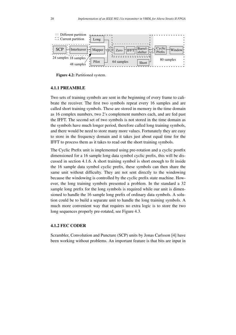
This to simplify test and verification by limiting the scope of the testingneeded and because the first parts, the scrambler, convolutional encoder andpuncturing, (SCP) had already been placed in a group. In addition, this designwould allow the parts to run at different sample rates, for an example seeFigure 4.2. However, this is not an advantage in this globally synchronoussystem using the same clock everywhere. When a subsystem could go sloweror be turned off it is instead in a waiting state. As an example, the IFFT mustwait samples. For information on a system partitioned to runwithout waiting states using a Global Asynchronous Locally Synchronous(GALS) approach, see Jonas Carlsson [6].With the whole system implemented it can be said that a different partitioningplacing the mapper unit and the Cyclic Prefix and Window units in newblocks could have been a good partitioning based on sample rate but theywere put together with the IFFT to facilitate abstraction of the precision of thecomplex number representation.
Figure 4.1: Synchronous interface.
data valid
ready
data
block 1 block 2
80 64– 16=
20 Implementation of an IEEE 802.11a transmitter in VHDL for Altera Stratix II FPGA
4.1.1 PREAMBLE
Two sets of training symbols are sent in the beginning of every frame to cali-brate the receiver. The first two symbols repeat every 16 samples and arecalled short training symbols. These are stored in memory in the time domainas 16 complex numbers, two 2’s complement numbers each, and are fed pastthe IFFT. The second set of two symbols is not stored in the time domain asthe symbols have much longer period, therefore called long training symbols,and there would be need to store many more values. Fortunately they are easyto store in the frequency domain and it takes just about equal time for theIFFT to process them as it takes to read out the short training symbols.
The Cyclic Prefix unit is implemented using pre-rotation and a cyclic postfixdimensioned for a 16 sample long data symbol cyclic prefix, this will be dis-cussed in section 4.1.6. A short training symbol is short enough to fit insidethe 16 sample data symbol cyclic prefix, these symbols can then share thesame unit without difficulty. They are not sent directly to the windowingbecause the windowing is controlled by the cyclic prefix state machine. How-ever, the long training symbols presented a problem. In the standard a 32sample long prefix for the long symbols is required while our unit is dimen-sioned to handle the 16 sample long prefix of ordinary data symbols. A solu-tion could be to build a separate unit to handle the long training symbols. Amuch more convenient way that requires no extra logic is to store the twolong sequences properly pre-rotated, see Figure 4.3.
4.1.2 FEC CODER
Scrambler, Convolution and Puncture (SCP) units by Jonas Carlsson [4] havebeen working without problems. An important feature is that bits are input in
Figure 4.2: Partitioned system.
SCP Interleaver Mapper
Pilot
Zero IFFT Barrel-shifter
CyclicPrefix
Window
Long
Short
+
Different partitionCurrent partition
64 samples48 samples
24 samples80 samples18 samples

Chapter 4 – Implementation 21
chunks of 8 at a time instead of one by one and output in chunks of 16 bits.The only addition needed was the interface to other synchronous blocks asseen in Figure 4.1.
4.1.3 INTERLEAVING
Our FFT/IFFT requires data to be fed in an order different from that specifiedin the standard, see Figure 4.4. To solve this, the interleaver is modified tooutput data in the required order. In addition, the order in which referencesubcarriers, called pilots, are inserted needed to be changed accordingly, seesection 4.1.5.
This data manipulation was done using a block interleaver by Jonas Carlsson
Figure 4.3: Reordering of the long training symbols.
Figure 4.4: The IFFT requires a different input pattern.
1:16 17:32 33:4849:64 49:64
Cyclic Postfix UnitNormal operation:
Cyclic Postfix Unit
Result:
First Long symbol
Second Long symbol
Pre-rotated symbol.
1:16 17:32 33:4849:64
1:16 17:3233:48 49:641:16 17:3233:48 49:64 33:48
1:16 17:32 33:4849:641:16 17:32 33:4849:64 49:64
1:16 17:32 33:4849:64 49:641:16 17:3233:48 49:64 33:48
#1#2:
#26Null
Null#-26
:#-2#-1Null
:
:

22 Implementation of an IEEE 802.11a transmitter in VHDL for Altera Stratix II FPGA
[4]. The interleaver is using an input buffer block where input data isordered.
At 64-QAM, 288 bits are written per symbol. With an input bus of 16 bits andan encoding rate of it takes clock cycles (cc) to fill the buffer.The interleaving operation reads output from the buffer in a different patternthan writing input, so it requires all bits of a symbol to be in the buffer. Whenall bits are in the buffer, output can be delivered immediately. Data for thenext symbol cannot be written to the buffer until all bits of the current symbolhave been delivered to the next unit, the mapper. The mapper takes 64 cc tocomplete a symbol and then waits 16 cc. These 16 cc are insufficient to com-plete writing to the interleaver buffer, output delivery must start at least
cc before the memory is available. The simple solutionapplied is to pipeline the interleaver by adding another buffer thereby givingus 64 more cc to fill the buffer. This setup allows higher throughput as inputcan be written and output can be read simultaneously. In fact, without thissetup the interleaver would be the bottleneck of the design.
Another issue is the logic depth created by the interleaving in conjunctionwith the mapping and rotation. The critical path is driven by the interleavercontrol unit and controls logic all the way to the IFFT. This critical path limitsthe system maximum clock frequency to 66 MHz. Fortunately this is wellwithin the requiremements as a 20 MHz clock will give the desired through-put. With interleaving logic placed before the output buffer, the logic depthwould be reduced. Such a solution has been designed but not integrated as thecurrent design already fulfills the requirements.
4.1.4 MAPPING
This is where the bits are mapped to complex numbers. The mapping is doneby tables using the bits and the data rate as input, see Table 4.1 to Table 4.4.Mapping tables. I- and Q-values are multiplied by a data rate dependent fac-tor to make the mean signal power equal to 1.
2
3---
288
16---------
2
3---÷ 27=
27 16– 11=

Chapter 4 – Implementation 23
The mapper control unit was assigned the task of controlling both the pilotinsertion and the rotation. This was done because the control unit holds the
Table 4.1: BPSK encoding table
Input bit(b0) I Q
0 -1 0
1 1 0
Table 4.2: QPSK encoding table
Input bit(b0) I Input bit(b1) Q
0 -1 0 -1
1 1 1 1
Table 4.3: 16-QAM encoding table
Input bit(b0b1) I Input bit(b2b3) Q
00 -3 00 -3
01 -1 01 -1
11 1 11 1
10 3 10 3
Table 4.4: 64-QAM encoding table
Input bit(b0b1b2) I Input bit(b3b4b5) Q
000 -7 000 -7
001 -5 001 -5
011 -3 011 -3
010 -1 010 -1
110 1 110 1
111 3 111 3
101 5 101 5
100 7 100 7

24 Implementation of an IEEE 802.11a transmitter in VHDL for Altera Stratix II FPGA
information of which subcarrier is being fed to the FFT. It could also becharged with keeping control of zero-insertion for the same reason. Howeveras consideration was taken with respect to sample rate, the zero-insertion wasplaced with the IFFT. The zero-insertion then knows which subcarrier isbeing fed to the IFFT, and could then also have controlled rotation and pilot-insertion. However, the pilot-insertion was left with the mapper because itrequires information on which symbol is the last, to restart itself, and thisinformation would then not need to be sent to the IFFT-block. Currently themapper runs at 52 samples but could in a different implementation run ateither 48 or 64.
4.1.5 PILOT-INSERTION
The pilots are generated using a scrambler with the “all ones” initial state, seesection 2.2.2. The subcarriers are inserted at positions -21, -7, 7, 21, seeFigure 4.4. Subcarrier at position 21 is always negated compared to the otherpilots. When the last data of the frame is sent this unit is restarted.
4.1.6 ROTATION
There was an issue that arose from the way the cyclic prefix (CP) is working.As said in 2.2.6 the Cyclic Prefix unit should copy the last 16 samples of thesymbol containing 64 samples and place them first to extend the symbol. Aneasy way to do this would be to delay and save all the samples from the IFFTby using a buffer and read the samples out in the right order. The buffer wouldthen delay output by 64 samples and take up bits. Thedelay would mean that the transmitter has increased latency from a request totransmission start or that the long training symbols must be stored in thememory-expensive time domain. For comparison, the interleaver takes up
bits. However, a delay can be seen as a time shift in the timedomain. In the frequency domain this is equivalent to a phase shift,
. (4.1)
By inserting a phase shift, or rotation as it can be seen in the complex plane,before the IFFT, the subcarriers come out of the IFFT with the last 16 sam-ples first. Now, only 16 samples need saving, no latency is created and thebuffer memory requirement is cut by four.
2 16 64×× 2048=
2 288 576=×
FourierTransform f x α–( )( ) F Ω( ) eαΩi–×=

Chapter 4 – Implementation 25
The 16 samples are a quarter of an IFFT period , a quarterperiod of a sine wave is . Subcarrier is multiplied by
. (4.2)
The implementation is done using a state machine that alternates betweenmultiplying by
, , and . (4.3)
In hardware means and . For allthe multiplication states the result can be obtained by using +1 adders, invert-ers and swapping of real and imaginary data buses as needed.
4.1.7 ZERO-INSERTION
To supply the zeroes needed, see Figure 2.3, this unit inserts zeroes andrequests data from the mapper when needed. As zero-insertion, IFFT andshifting are hidden within a single entity, managment of the zeroes isabstracted from the external flow.
4.1.8 IFFT
This unit preforms the IDFT needed for the OFDM. It is implemented as anFFT/IFFT IP-core provided by Altera [2]. Its frequency-domain input is asequence of 64 complex numbers, each represented as two 16-bit 2’s comple-ment numbers with 15 decimal bits, forming a fix-point representation. Thetime-domain output is a sequence of 64 complex numbers each represented astwo 16-bit 2’s complement numbers with 15 decimal bits both scaled as ablock by a 6-bit exponent, forming a block floating-point representation.
4.1.9 SHIFTING
The IFFT produces block floating-point output, this unit converts it back tofix-point representation. It removes the need of passing the exponent along byshifting the output back into its proper range using the exponent, seeequation (4.4). The unit is implemented as a barrelshifter and code can be
16 64⁄ 1 4⁄=( )2π 4⁄ π 2⁄= m
e
π2---– mi n2π±
n N∈,
e
π2--- i–
i–= eπi
1–= e
π2--- i
i= e0i
1=
a bi+( ) i–× b ai–= re im⇐ im not re( ) 1+⇐

26 Implementation of an IEEE 802.11a transmitter in VHDL for Altera Stratix II FPGA
generated to manage shifts where . However, testing indicated to be sufficient.
, (4.4)
where e is the exponent and s is the number of shifts.
4.1.10 CYCLIC PREFIX
This unit copies the first 16 values from the IFFT into a buffer and writesthem back when the IFFT has finished clock cycles later, inpractice producing a postfix, see Figure 4.5. This is made possible by the therotation, see section 4.1.6. After adding a cyclic prefix by producing a postfixof the prerotated symbol, each symbol is samples long. TheIFFT period of 64 samples means that the IFFT must be in a 16 clock cyclelong waiting state while the Cyclic Postfix unit adds the last 16 samples to thesequence. As can be seen in Figure 4.2, this part has the highest sample rate.However, with proper buffering the Cyclic Postfix unit could run at 32 sam-ples, (16 for copying to the buffer and 16 to write from the buffer) and allowthe IFFT to work without waiting states.
4.1.11 WINDOWING
This unit trims the edges of the symbol by taking the average of the last sam-ple of the previous symbol and the first sample of the next symbol and plac-ing it at the first sample of the next symbol. This can be described as
(4.5)
where a is the previous symbol and b is the next symbol. The last term isadded only to the last symbol of a frame.
Figure 4.5: Cyclic Prefix by postfix.
n± n N∈n 2=
s e– 6– not e( ) 1+( ) 6– not e( ) 2′s complement 5–( )+= = =
64 16– 48=
16 64+ 80=
1:16 17:32 33:4849:64 49:64
Cyclic Postfix Unit Pre-rotated symbol.
1:16 17:32 33:4849:64
1
2--- b0 a16+( )δ t[ ] b1δ t 1+[ ] … b79+ δ t 79+[ ]
1
2---b
16δ t 80+[ ]
++ +

27
5
TESTING
5.1 TEST SETUP
The testing can be divided into two phases, a simulation phase where all test-ing is done on the PC and a hardware phase where testing is done on the hard-ware. In Figure 5.1 an overview can be seen. Note that there are more stepsinvolved in extracting testdata in the hardware phase.
5.1.1 SIMULATION
Modelsim tests were run when changes were made to the system. Test-benches were developed to read test input data produced by a MATLABmodel and to gererate MATLAB-readable output data. Data representationcould then be changed to allow comparison with reference data produced by
Figure 5.1: Test setup overview.
Matlab
Simulation:
Matlab
Hardware:
Minicom 2.0
SRAMFlow control
RS232
FPGA
FIFOs
SystemInterface
Serial bus
PC
PCSystem
Testbench
Modelsim

28 Implementation of an IEEE 802.11a transmitter in VHDL for Altera Stratix II FPGA
the MATLAB model and error patterns were studied to determine the causeof errors.
5.1.2 HARDWARE
In the later stages where all components had been developed data was readand stored in on-chip SRAM memory and accessed using scripts for Minicom2.0 through a serial port (RS232) interface [9].
5.2 TEST RESULT
The IEEE 802.11a standard contains a conformance test consisting of a 108octet long data stream encoded with a data rate of 6 MBit/s. To test also theother data rates, other data streams and sending of multiple frames insequence, many more test suites were produced by the simulink model. Allthe tests have been passed successfully. It can be mentioned that the currentimplementation has very low latency, the first output is produced only 2 clockcycles after a request is made, and the rest of the frame can be delivered insequence without any further delay.

29
6
CONCLUSION
6.1 SUMMARY
Some telecommunications theory and WLAN theory in particular was intro-duced. An implementation of the transmitter part of a 802.11a physical layerand problems encountered were described and the testing procedures wereoutlined.
6.2 RESULT
An implementation of the transmitter part of a 802.11a PHY layer was com-pleted and tested successfully on the FPGA. It can be said that the vast major-ity of time spent was on the synthesis and verification, especially verification.VHDL code operating correctly after unit testing was largely left unchangedthrough the design process, the main problems were to make sure the systembehaved as expected in later stages, and to add new functionality to allowembedded verification. A solid VHDL experience is recommended beforetaking on a project like this as many errors could have been avoided.
Another version of a block interleaver was designed and unit-tested but notintegrated, and a convolutional interleaver considered but not designed sincethe current design proved satisfactory. There are many different partitioningsleft untested, but although it is recognised that some may be more efficient interms of sample rate, the current partitioning is very efficient in terms ofabstraction.
The testing with data processing in MATLAB proved very useful. The stand-ard and the MATLAB model producing reference data both used a data repre-sentation different from what the implementation produced.

30 Implementation of an IEEE 802.11a transmitter in VHDL for Altera Stratix II FPGA
6.3 FUTURE WORK
To complete a 802.11a PHY layer system a receiver and interfaces conform-ing to the standard would need to be implemented and tested.

31
REFERENCES
[1]International Standard ISO/IEC 8802-11:1999/Amd 1:2000(E) IEEE Std 802.11a-1999.
[2]Altera, http://www.altera.com (2006, Apr.)
[3]www.mathworks.com (2006, Feb.)
[4]Discussions with Jonas Carlsson.
[5]www.mentorgraphics.com (2006, Feb.)
[6]J. Carlsson, Studies on Asynchronous Communication Ports for GALS systems,Lic. thesis, Linköpings universitet, June 2005.
[7]Richard van Nee and Ramjee Prasad, OFDM for Wireless Multimedia Communi-cations, Artech House, 2000.
[8]Juha Heiskala and John Terry, OFDM Wireless LANs: A theoretical and PracticalGuide, Sams Publishing, 2002.
[9]P. Kröger, Design of a debugging interface between FPGA Design and SRAMdevice, documentation and manual, ISY, Linköpings universitet, Feb 2006.

32 Implementation of an IEEE 802.11a transmitter in VHDL for Altera Stratix II FPGA

På svenska
Detta dokument hålls tillgängligt på Internet – eller dess framtida ersättare – under en längre tid frånpubliceringsdatum under förutsättning att inga extra-ordinära omständigheter uppstår.
Tillgång till dokumentet innebär tillstånd för var och en att läsa, ladda ner, skriva ut enstaka kopior förenskilt bruk och att använda det oförändrat för ickekommersiell forskning och för undervisning. Över-föring av upphovsrätten vid en senare tidpunkt kan inte upphäva detta tillstånd. All annan användningav dokumentet kräver upphovsmannens medgivande. För att garantera äktheten, säkerheten ochtillgängligheten finns det lösningar av teknisk och administrativ art.
Upphovsmannens ideella rätt innefattar rätt att bli nämnd som upphovsman i den omfattning som godsed kräver vid användning av dokumentet på ovan beskrivna sätt samt skydd mot att dokumentet ändraseller presenteras i sådan form eller i sådant sammanhang som är kränkande för upphovsmannens lit-terära eller konstnärliga anseende eller egenart.
För ytterligare information om Linköping University Electronic Press se förlagets hemsida http://www.ep.liu.se/
In English
The publishers will keep this document online on the Internet - or its possible replacement - for a con-siderable time from the date of publication barring exceptional circumstances.
The online availability of the document implies a permanent permission for anyone to read, to down-load, to print out single copies for your own use and to use it unchanged for any non-commercialresearch and educational purpose. Subsequent transfers of copyright cannot revoke this permission. Allother uses of the document are conditional on the consent of the copyright owner. The publisher hastaken technical and administrative measures to assure authenticity, security and accessibility.
According to intellectual property law the author has the right to be mentioned when his/her work isaccessed as described above and to be protected against infringement.
For additional information about the Linköping University Electronic Press and its procedures for pub-lication and for assurance of document integrity, please refer to its WWW home page: http://www.ep.liu.se/
© Johannes Brännström


