Abstract— This article presents an ac efficient Automobile (especially Car) secu improve the owner’s ease. This system sensor network (WSN). A WSN co autonomous sensors to monitor physic vibration, pressure, motion and to cooper through the network to a main locatio Keyless Entry (RKE) System was deve door locking and ignition starter, whic overcome them Car Security System (C and this is achieved by employing lo wireless sensors inside the car. Lockin Central locking, Ignition circuit breaker Transmission lock. Different wireless se sensors, Pressure sensors which contin physical changes occurring in the car, c Electronic Control Module (ECM) h controlled by owner’s computer via (49 M Index Terms— CSS, RF, RKE, WSN. I. INTRODUCTIO The recent tremendous growth in c develop security systems which can ra as protect the car. Due to this, car comp keyless entry system. An RKE [1] syst transmitter in the key fob (or key) that digital data to a receiver in the vehicle and made to open or close the vehicle d receivercontrolled actuators. The wire [7]is currently 433.92MHz (ISM band) modulation is frequency-shift keying other parts of the world, ampli orASKisused.The carrierisamplitude m levels: To save power, the lower level producing complete on-off keying (OO In the vehicle, an RF [4] receiver ca directs it to another microcontroller, w and sends an appropriate message to sta the door. Multi-buttons key fobs give t the driver's door, or all doors, or the tru Improvement in Controlled by Dependra Nat International Journal of Electronics, Communication & S 26 ccurate, fast and very urity system which will m is based on wireless onsists of distributed cal conditions such as ratively pass their data on. Previously Remote eloped which provides ch had drawbacks. To CSS) can be developed ocking techniques and ng techniques include r, Fuel supply lock and ensors utilized are Tilt nuously monitor the communicated with the having software CSS MHz) RF link. ON car thieves leads to ang the alarm as well panies develop remote tem consists of an RF sends a short burst of e, where it is decoded doors or the trunk via eless carrierfrequency ) inIndia. In India the (FSK), but in most itude -shift keying, modulated between two l is usually near zero, OK). aptures that data and which decodes the data art the engine or open the choice of opening unk, etc. The digital data stream, trans 20kbps, usually consists of a code, some check bits, and a vehicle security by altering itsel rolling code, your transmitted unlock another vehicle or fall who could use it to gain entry la RKE [6] is strictly a short- meters, or 1 to 2 meters for pas even a short transmission distan cost design Figure 1.1: An RKE system consists o figure) transmitting to a r (upper part of challenging the RF circuitry. F and receiver antennas consist loop of copper trace on a small network to match the antenna i receive chip. The system [5] shown in fig. The transmitter's and receive memory location that holds the push a button on your key fob, with a function code that tells (lock the doors, unlock the door Both the transmitter and the re random number generator. Whe bit code, it uses the pseudo-r pick a new code, which it stor end, when the receiver receives pseudo-random number generat n Automobile Security y Personal Computer v Link th Saikia, Abhilasha Choudhary, Aditi Sardesai Soft Computing Science and Engineering ISSN: 2277-9477, Volume 2, Issue1 smitted between 2.4kbps and data preamble, a command "rolling code" that ensures lf with each use. Without this d signal might accidentally into the hands of a car thief ater. -range technology, up to 20 ssive RKE systems. Ensuring nce on low power and a low- budgetcan be of a key fob circuit (lower part of the receiver in the vehicle the figure). For simplicity, the transmitter of a circular or rectangular l PC board, with a simple LC impedance to the transmit or .1.1 uses 8-bits rolling code. er’s controller chip has a current 8-bit code. When you it sends that 8-bit code along the car what you want to do rs, open the trunk, etc.). eceiver use the same pseudo- en the transmitter sends a 40- random number generator to res in memory. On the other a valid code, it uses the same tor to pick a new one. In this y System via RF
Transcript
International Journal of Electronics, Communication & Soft Computing Science and EngineeringISSN: 2277-9477, Volume 2, Issue1
26
Abstract— This article presents an accurate, fast and veryefficient Automobile (especially Car) security system which willimprove the owner’s ease. This system is based on wirelesssensor network (WSN). A WSN consists of distributedautonomous sensors to monitor physical conditions such asvibration, pressure, motion and to cooperatively pass their datathrough the network to a main location. Previously RemoteKeyless Entry (RKE) System was developed which providesdoor locking and ignition starter, which had drawbacks. Toovercome them Car Security System (CSS) can be developedand this is achieved by employing locking techniques andwireless sensors inside the car. Locking techniques includeCentral locking, Ignition circuit breaker, Fuel supply lock andTransmission lock. Different wireless sensors utilized are Tiltsensors, Pressure sensors which continuously monitor thephysical changes occurring in the car, communicated with theElectronic Control Module (ECM) having software CSScontrolled by owner’s computer via (49 MHz) RF link.
Index Terms— CSS, RF, RKE, WSN.
I. INTRODUCTION
The recent tremendous growth in car thieves leads todevelop security systems which can rang the alarm as wellas protect the car. Due to this, car companies develop remotekeyless entry system. An RKE [1] system consists of an RFtransmitter in the key fob (or key) that sends a short burst ofdigital data to a receiver in the vehicle, where it is decodedand made to open or close the vehicle doors or the trunk viareceivercontrolled actuators. The wireless carrierfrequency[7]is currently 433.92MHz (ISM band) inIndia. In India themodulation is frequency-shift keying (FSK), but in mostother parts of the world, amplitude -shift keying,orASKisused.The carrierisamplitude modulated between twolevels: To save power, the lower level is usually near zero,producing complete on-off keying (OOK).In the vehicle, an RF [4] receiver captures that data anddirects it to another microcontroller, which decodes the dataand sends an appropriate message to start the engine or openthe door. Multi-buttons key fobs give the choice of openingthe driver's door, or all doors, or the trunk, etc.
The digital data stream, transmitted between 2.4kbps and20kbps, usually consists of a data preamble, a commandcode, some check bits, and a "rolling code" that ensuresvehicle security by altering itself with each use. Without thisrolling code, your transmitted signal might accidentallyunlock another vehicle or fall into the hands of a car thiefwho could use it to gain entry later.
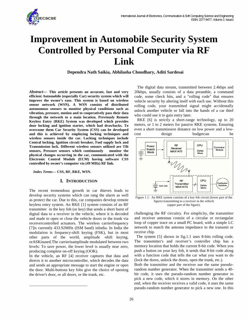
RKE [6] is strictly a short-range technology, up to 20meters, or 1 to 2 meters for passive RKE systems. Ensuringeven a short transmission distance on low power and a low-cost design budgetcan be
Figure 1.1: An RKE system consists of a key fob circuit (lower part of thefigure) transmitting to a receiver in the vehicle
(upper part of the figure).
challenging the RF circuitry. For simplicity, the transmitterand receiver antennas consist of a circular or rectangularloop of copper trace on a small PC board, with a simple LCnetwork to match the antenna impedance to the transmit orreceive chip.
The system [5] shown in fig.1.1 uses 8-bits rolling code.The transmitter's and receiver’s controller chip has amemory location that holds the current 8-bit code. When youpush a button on your key fob, it sends that 8-bit code alongwith a function code that tells the car what you want to do(lock the doors, unlock the doors, open the trunk, etc.).Both the transmitter and the receiver use the same pseudo-random number generator. When the transmitter sends a 40-bit code, it uses the pseudo-random number generator topick a new code, which it stores in memory. On the otherend, when the receiver receives a valid code, it uses the samepseudo-random number generator to pick a new one. In this
Improvement in Automobile Security SystemControlled by Personal Computer via RF
International Journal of Electronics, Communication & Soft Computing Science and EngineeringISSN: 2277-9477, Volume 2, Issue1
26
Abstract— This article presents an accurate, fast and veryefficient Automobile (especially Car) security system which willimprove the owner’s ease. This system is based on wirelesssensor network (WSN). A WSN consists of distributedautonomous sensors to monitor physical conditions such asvibration, pressure, motion and to cooperatively pass their datathrough the network to a main location. Previously RemoteKeyless Entry (RKE) System was developed which providesdoor locking and ignition starter, which had drawbacks. Toovercome them Car Security System (CSS) can be developedand this is achieved by employing locking techniques andwireless sensors inside the car. Locking techniques includeCentral locking, Ignition circuit breaker, Fuel supply lock andTransmission lock. Different wireless sensors utilized are Tiltsensors, Pressure sensors which continuously monitor thephysical changes occurring in the car, communicated with theElectronic Control Module (ECM) having software CSScontrolled by owner’s computer via (49 MHz) RF link.
Index Terms— CSS, RF, RKE, WSN.
I. INTRODUCTION
The recent tremendous growth in car thieves leads todevelop security systems which can rang the alarm as wellas protect the car. Due to this, car companies develop remotekeyless entry system. An RKE [1] system consists of an RFtransmitter in the key fob (or key) that sends a short burst ofdigital data to a receiver in the vehicle, where it is decodedand made to open or close the vehicle doors or the trunk viareceivercontrolled actuators. The wireless carrierfrequency[7]is currently 433.92MHz (ISM band) inIndia. In India themodulation is frequency-shift keying (FSK), but in mostother parts of the world, amplitude -shift keying,orASKisused.The carrierisamplitude modulated between twolevels: To save power, the lower level is usually near zero,producing complete on-off keying (OOK).In the vehicle, an RF [4] receiver captures that data anddirects it to another microcontroller, which decodes the dataand sends an appropriate message to start the engine or openthe door. Multi-buttons key fobs give the choice of openingthe driver's door, or all doors, or the trunk, etc.
The digital data stream, transmitted between 2.4kbps and20kbps, usually consists of a data preamble, a commandcode, some check bits, and a "rolling code" that ensuresvehicle security by altering itself with each use. Without thisrolling code, your transmitted signal might accidentallyunlock another vehicle or fall into the hands of a car thiefwho could use it to gain entry later.
RKE [6] is strictly a short-range technology, up to 20meters, or 1 to 2 meters for passive RKE systems. Ensuringeven a short transmission distance on low power and a low-cost design budgetcan be
Figure 1.1: An RKE system consists of a key fob circuit (lower part of thefigure) transmitting to a receiver in the vehicle
(upper part of the figure).
challenging the RF circuitry. For simplicity, the transmitterand receiver antennas consist of a circular or rectangularloop of copper trace on a small PC board, with a simple LCnetwork to match the antenna impedance to the transmit orreceive chip.
The system [5] shown in fig.1.1 uses 8-bits rolling code.The transmitter's and receiver’s controller chip has amemory location that holds the current 8-bit code. When youpush a button on your key fob, it sends that 8-bit code alongwith a function code that tells the car what you want to do(lock the doors, unlock the doors, open the trunk, etc.).Both the transmitter and the receiver use the same pseudo-random number generator. When the transmitter sends a 40-bit code, it uses the pseudo-random number generator topick a new code, which it stores in memory. On the otherend, when the receiver receives a valid code, it uses the samepseudo-random number generator to pick a new one. In this
Improvement in Automobile Security SystemControlled by Personal Computer via RF
International Journal of Electronics, Communication & Soft Computing Science and EngineeringISSN: 2277-9477, Volume 2, Issue1
27
way, the transmitter and the receiver are synchronized. Thereceiver only opens the door if it receives the code itexpects.If you are a mile away from your car and accidentally pushthe button on the transmitter [2], thetransmitterandreceiverareno longer synchronized. Thereceiver solves this problem by accepting any of the next256 possible valid codes in the pseudo-random numbersequence. This way, you (or your three-year-old child)could"accidentally" push a button on the transmitter up to 256times and it would be okay -- the receiver would still acceptthe transmission and perform therequestedfunction.However,ifyou accidentally push thebutton 257 times, the receiver will totally ignore yourtransmitter. It won't work anymore.But this system has limitations, like:
It wouldn’t work more than 20m range [3]. If a thief monitors the signal sent by the same key
fob for 20-30 times, then he could easilyunderstand the pattern of code generation by thepseudo code generator and easily copy on RadioFrequency transmitter.
Desynchronizing problem causes headache to theuser.
II. PROPOSEDCARSECURITYSYSTEM
Figure 2.1: Proposed car security system.
In the above figure 2.1, there are two parts: one at thecomputer side and the other at the car side. Now at the carside, the ECM comprises of Transmitter/Receiver, CPU andMemory module. At the computer side, CSS softwarecontrols all operations of ECM. It communicates with theReceiver/ Transmitter at the computer side through RF Link.
Moreover, the CPU at the ECM commands the various locksand sensors connected to it. ECM is mounted on the lowerpart of the bonnet.
A. Different Locks and Sensors Utilized-
Figure 2.2: Various sensors used for car security
1) Centraldoorlock
Figure 2.3: An actuator used in modern cars.
The locking/unlocking of power doors lock is actuallyperformed by actuators shown in fig.2.3.These are placed inthe doors. Two types of actuators are in common use:1. Solenoid: The solenoid is an electromagnetic switch. Itlocks the doors when current passed in it by the ECM in onedirection and unlocks when the direction of current isreversed.2. Motor: In place of solenoid, DC motors can also be usedas actuator as shown in fig.2.4. The rotary motion of themotor is converted to linear motion by means of rack andpinion mechanisms. Again by changing the directions ofcurrent rotation direction of motor is changed .Thus it locksfor one direction of current decided by the ECM and unlocksfor opposite direction.
International Journal of Electronics, Communication & Soft Computing Science and EngineeringISSN: 2277-9477, Volume 2, Issue1
28
Figure 2.4: Internal view of actuator
2) Ignition Lock
Figure 2.5: Ignition circuit of a car.
An ignition system is mainly a circuit comprising ofbattery, relay, connector to crank shaft shown if fig.2.5.Until completion of circuit, it will not work; this feature isused in ignition lock system. Even if key is inserted andRelay is not on, circuit not completed. Relay is controlled byCar Electronic Control Module (ECM).ECM is command bycar’s owner computer.
3) Fuel SupplyLockAs Shown in fig.2.6, Motor controlled valve is present in thepipe from petrol tank to engine. The motor’s linearmovement is used to open/close the valve. When relay ismagnetized, it completes the circuit and motor works inforward direction to close the valve.
Figure 2.6: Relay controlling the valve in petrol pipeline byusing motor.
When relay is demagnetized, motor gets positive chargefrom current line and open relay connection work as groundand circuit is complete, motor works in reverse direction andopen the valve.By this, if a thief able to break the ignitionbreak then also he couldn’t start the car.
4) Transmission Lock
Figure 2.7: Drive Shaft lock in a car.
Transmission power of engine goes to rear wheels of a carthrough the drive shaft. If a thiefis able to hijack fuel supplylock and starts engine, he can take away the car. But wecreated Transmission locking system shown in fig. 2.7.,which blocks supply to the rear wheels by locking the driveshaft.
International Journal of Electronics, Communication & Soft Computing Science and EngineeringISSN: 2277-9477, Volume 2, Issue1
29
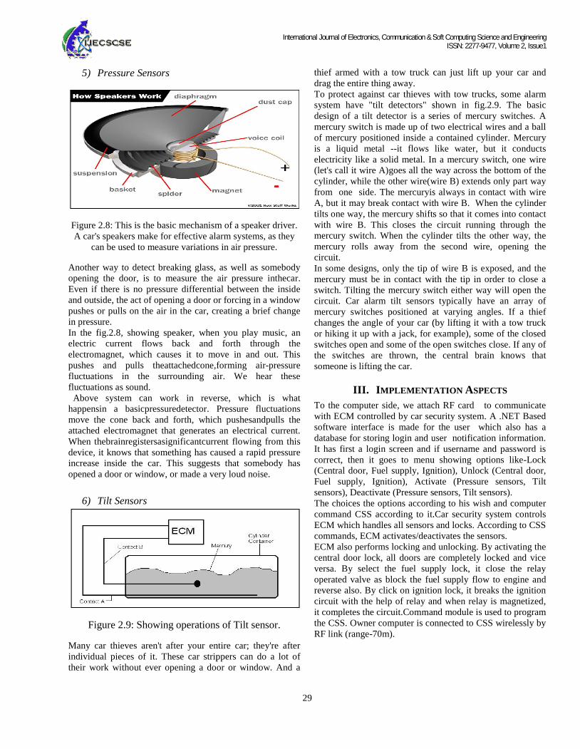
5) Pressure Sensors
Figure 2.8: This is the basic mechanism of a speaker driver.A car's speakers make for effective alarm systems, as they
can be used to measure variations in air pressure.
Another way to detect breaking glass, as well as somebodyopening the door, is to measure the air pressure inthecar.Even if there is no pressure differential between the insideand outside, the act of opening a door or forcing in a windowpushes or pulls on the air in the car, creating a brief changein pressure.In the fig.2.8, showing speaker, when you play music, anelectric current flows back and forth through theelectromagnet, which causes it to move in and out. Thispushes and pulls theattachedcone,forming air-pressurefluctuations in the surrounding air. We hear thesefluctuations as sound.
Above system can work in reverse, which is whathappensin a basicpressuredetector. Pressure fluctuationsmove the cone back and forth, which pushesandpulls theattached electromagnet that generates an electrical current.When thebrainregistersasignificantcurrent flowing from thisdevice, it knows that something has caused a rapid pressureincrease inside the car. This suggests that somebody hasopened a door or window, or made a very loud noise.
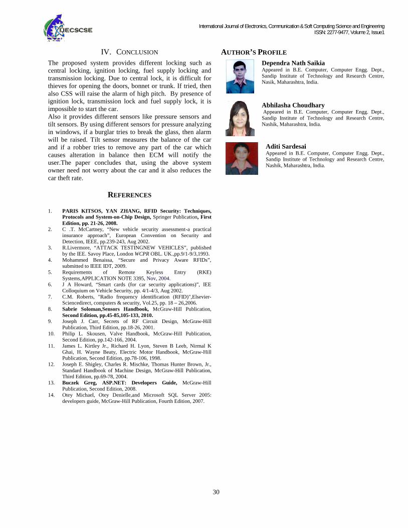
6) Tilt Sensors
Figure 2.9: Showing operations of Tilt sensor.
Many car thieves aren't after your entire car; they're afterindividual pieces of it. These car strippers can do a lot oftheir work without ever opening a door or window. And a
thief armed with a tow truck can just lift up your car anddrag the entire thing away.To protect against car thieves with tow trucks, some alarmsystem have "tilt detectors" shown in fig.2.9. The basicdesign of a tilt detector is a series of mercury switches. Amercury switch is made up of two electrical wires and a ballof mercury positioned inside a contained cylinder. Mercuryis a liquid metal --it flows like water, but it conductselectricity like a solid metal. In a mercury switch, one wire(let's call it wire A)goes all the way across the bottom of thecylinder, while the other wire(wire B) extends only part wayfrom one side. The mercuryis always in contact with wireA, but it may break contact with wire B. When the cylindertilts one way, the mercury shifts so that it comes into contactwith wire B. This closes the circuit running through themercury switch. When the cylinder tilts the other way, themercury rolls away from the second wire, opening thecircuit.In some designs, only the tip of wire B is exposed, and themercury must be in contact with the tip in order to close aswitch. Tilting the mercury switch either way will open thecircuit. Car alarm tilt sensors typically have an array ofmercury switches positioned at varying angles. If a thiefchanges the angle of your car (by lifting it with a tow truckor hiking it up with a jack, for example), some of the closedswitches open and some of the open switches close. If any ofthe switches are thrown, the central brain knows thatsomeone is lifting the car.
III. IMPLEMENTATION ASPECTS
To the computer side, we attach RF card to communicatewith ECM controlled by car security system. A .NET Basedsoftware interface is made for the user which also has adatabase for storing login and user notification information.It has first a login screen and if username and password iscorrect, then it goes to menu showing options like-Lock(Central door, Fuel supply, Ignition), Unlock (Central door,Fuel supply, Ignition), Activate (Pressure sensors, Tiltsensors), Deactivate (Pressure sensors, Tilt sensors).The choices the options according to his wish and computercommand CSS according to it.Car security system controlsECM which handles all sensors and locks. According to CSScommands, ECM activates/deactivates the sensors.ECM also performs locking and unlocking. By activating thecentral door lock, all doors are completely locked and viceversa. By select the fuel supply lock, it close the relayoperated valve as block the fuel supply flow to engine andreverse also. By click on ignition lock, it breaks the ignitioncircuit with the help of relay and when relay is magnetized,it completes the circuit.Command module is used to programthe CSS. Owner computer is connected to CSS wirelessly byRF link (range-70m).
International Journal of Electronics, Communication & Soft Computing Science and EngineeringISSN: 2277-9477, Volume 2, Issue1
29
5) Pressure Sensors
Figure 2.8: This is the basic mechanism of a speaker driver.A car's speakers make for effective alarm systems, as they
can be used to measure variations in air pressure.
Another way to detect breaking glass, as well as somebodyopening the door, is to measure the air pressure inthecar.Even if there is no pressure differential between the insideand outside, the act of opening a door or forcing in a windowpushes or pulls on the air in the car, creating a brief changein pressure.In the fig.2.8, showing speaker, when you play music, anelectric current flows back and forth through theelectromagnet, which causes it to move in and out. Thispushes and pulls theattachedcone,forming air-pressurefluctuations in the surrounding air. We hear thesefluctuations as sound.
Above system can work in reverse, which is whathappensin a basicpressuredetector. Pressure fluctuationsmove the cone back and forth, which pushesandpulls theattached electromagnet that generates an electrical current.When thebrainregistersasignificantcurrent flowing from thisdevice, it knows that something has caused a rapid pressureincrease inside the car. This suggests that somebody hasopened a door or window, or made a very loud noise.
6) Tilt Sensors
Figure 2.9: Showing operations of Tilt sensor.
Many car thieves aren't after your entire car; they're afterindividual pieces of it. These car strippers can do a lot oftheir work without ever opening a door or window. And a
thief armed with a tow truck can just lift up your car anddrag the entire thing away.To protect against car thieves with tow trucks, some alarmsystem have "tilt detectors" shown in fig.2.9. The basicdesign of a tilt detector is a series of mercury switches. Amercury switch is made up of two electrical wires and a ballof mercury positioned inside a contained cylinder. Mercuryis a liquid metal --it flows like water, but it conductselectricity like a solid metal. In a mercury switch, one wire(let's call it wire A)goes all the way across the bottom of thecylinder, while the other wire(wire B) extends only part wayfrom one side. The mercuryis always in contact with wireA, but it may break contact with wire B. When the cylindertilts one way, the mercury shifts so that it comes into contactwith wire B. This closes the circuit running through themercury switch. When the cylinder tilts the other way, themercury rolls away from the second wire, opening thecircuit.In some designs, only the tip of wire B is exposed, and themercury must be in contact with the tip in order to close aswitch. Tilting the mercury switch either way will open thecircuit. Car alarm tilt sensors typically have an array ofmercury switches positioned at varying angles. If a thiefchanges the angle of your car (by lifting it with a tow truckor hiking it up with a jack, for example), some of the closedswitches open and some of the open switches close. If any ofthe switches are thrown, the central brain knows thatsomeone is lifting the car.
III. IMPLEMENTATION ASPECTS
To the computer side, we attach RF card to communicatewith ECM controlled by car security system. A .NET Basedsoftware interface is made for the user which also has adatabase for storing login and user notification information.It has first a login screen and if username and password iscorrect, then it goes to menu showing options like-Lock(Central door, Fuel supply, Ignition), Unlock (Central door,Fuel supply, Ignition), Activate (Pressure sensors, Tiltsensors), Deactivate (Pressure sensors, Tilt sensors).The choices the options according to his wish and computercommand CSS according to it.Car security system controlsECM which handles all sensors and locks. According to CSScommands, ECM activates/deactivates the sensors.ECM also performs locking and unlocking. By activating thecentral door lock, all doors are completely locked and viceversa. By select the fuel supply lock, it close the relayoperated valve as block the fuel supply flow to engine andreverse also. By click on ignition lock, it breaks the ignitioncircuit with the help of relay and when relay is magnetized,it completes the circuit.Command module is used to programthe CSS. Owner computer is connected to CSS wirelessly byRF link (range-70m).
International Journal of Electronics, Communication & Soft Computing Science and EngineeringISSN: 2277-9477, Volume 2, Issue1
30
IV. CONCLUSION
The proposed system provides different locking such ascentral locking, ignition locking, fuel supply locking andtransmission locking. Due to central lock, it is difficult forthieves for opening the doors, bonnet or trunk. If tried, thenalso CSS will raise the alarm of high pitch. By presence ofignition lock, transmission lock and fuel supply lock, it isimpossible to start the car.Also it provides different sensors like pressure sensors andtilt sensors. By using different sensors for pressure analyzingin windows, if a burglar tries to break the glass, then alarmwill be raised. Tilt sensor measures the balance of the carand if a robber tries to remove any part of the car whichcauses alteration in balance then ECM will notify theuser.The paper concludes that, using the above systemowner need not worry about the car and it also reduces thecar theft rate.
REFERENCES
1. PARIS KITSOS, YAN ZHANG, RFID Security: Techniques,Protocols and System-on-Chip Design, Springer Publication, FirstEdition, pp. 21-26, 2008.
2. C .T. McCartney, “New vehicle security assessment-a practicalinsurance approach”, European Convention on Security andDetection, IEEE, pp.239-243, Aug 2002.
3. R.Livermore, “ATTACK TESTINGNEW VEHICLES”, publishedby the IEE. Savoy Place, London WCPR OBL. UK.,pp.9/1-9/3,1993.
4. Mohammed Benaissa, “Secure and Privacy Aware RFIDs”,submitted to IEEE IDT, 2009.
9. Joseph J. Carr, Secrets of RF Circuit Design, McGraw-HillPublication, Third Edition, pp.18-26, 2001.
10. Philip L. Skousen, Valve Handbook, McGraw-Hill Publication,Second Edition, pp.142-166, 2004.
11. James L. Kirtley Jr., Richard H. Lyon, Steven B Leeb, Nirmal KGhai, H. Wayne Beaty, Electric Motor Handbook, McGraw-HillPublication, Second Edition, pp.78-106, 1998.
12. Joseph E. Shigley, Charles R. Mischke, Thomas Hunter Brown, Jr.,Standard Handbook of Machine Design, McGraw-Hill Publication,Third Edition, pp.69-78, 2004.
13. Buczek Greg, ASP.NET: Developers Guide, McGraw-HillPublication, Second Edition, 2008.
14. Otey Michael, Otey Denielle,and Microsoft SQL Server 2005:developers guide, McGraw-Hill Publication, Fourth Edition, 2007.
AUTHOR’S PROFILE
Dependra Nath SaikiaAppeared in B.E. Computer, Computer Engg. Dept.,Sandip Institute of Technology and Research Centre,Nasik, Maharashtra, India.
Abhilasha ChoudharyAppeared in B.E. Computer, Computer Engg. Dept.,
Sandip Institute of Technology and Research Centre,Nashik, Maharashtra, India.
Aditi SardesaiAppeared in B.E. Computer, Computer Engg. Dept.,Sandip Institute of Technology and Research Centre,Nashik, Maharashtra, India.