In-Situ Test of a Precast Pier of an Elevated Viaduct in Mexico City D. Murià-Vila, A.R. Sánchez-Ramírez & C. H. Huerta-Carpizo Instituto de Ingeniería, UNAM, Ciudad Universitaria, Coyoacán, 04510 México, D.F. L. R. Fernández-Sola Instituto de Ingeniería, UNAM, Ciudad Universitaria, Coyoacán, 04510 México, D.F Now at Departamento de Materiales, UAM-Azcapotzalco, Av. San Pablo 180, Reynosa Tamaulipas, 02200, México, D.F. SUMMARY: This paper presents the analysis of the lateral-load tests applied to a precast pier of an elevated viaduct in two stages of construction: one with the pier isolated and the other when the construction of the viaduct was concluded. The purpose was to identify the main mechanical properties of the pier and the soil-structure interaction effect, in order to determine the existence of any discrepancy between design and construction that might affect the structural safety of this and similar viaducts. The study allowed the verification of fundamental parameters considered for the design, detection of some construction aspects that can be simplified in similar future works, and increased the knowledge about the behavior of these types of structures. Keywords: Elevated viaduct, precast concrete, prestressed concrete, load test, soil-structure interaction effect 1. INTRODUCTION Addressing a special request of the local government of Mexico State, the Institute of Engineering of UNAM carried out a series of field tests on an elevated viaduct. The project consisted of the construction of a 32-km long superstructure with three lanes, which will help alleviating traffic problems in one of the busiest expressways of the city. The leading construction company adopted a system of precast prestressed concrete box girders resting on isolated supports formed by a precast prestressed pier-footing assembly that was founded on four reinforced concrete piles (Fig. 1.1). The superstructure was formed by Gerber-type girders, which were composed of several elements assembled in situ. Structure was designed based on AASHTO (2002) specifications, ACI (2008), SCT(2001) norms and the Mexico City construction code (NTCDF, 2004). Considering the importance of the structure and the seismic environment in Mexico City, a special field test program was designed and carried out. This paper presents the analysis of the lateral-load test carried out in a precast pier in two stages. The first-stage test was conducted during the construction of the viaduct (isolated pier) while the second-stage test took place after the construction of the viaduct was concluded. The objectives of the test were: a) to identify the main mechanical properties of the pier, b) to corroborate the seismic design hypotheses used, c) to determine the existence of any discrepancy between design and construction that might affect the structural safety of this and similar elevated expressways under construction, and d) to outline the need for adjustments in the design and construction cycles for similar future projects. In this paper the main results obtained from lateral-load test of the pier corresponding to axis A241 are presented. Tests were developed in two different stages of the construction (Fig. 1.2), in order of establish some of the main properties of its structural behavior.
Transcript
In-Situ Test of a Precast Pier of an
Elevated Viaduct in Mexico City
D. Murià-Vila, A.R. Sánchez-Ramírez & C. H. Huerta-Carpizo Instituto de Ingeniería, UNAM, Ciudad Universitaria, Coyoacán, 04510 México, D.F.
L. R. Fernández-Sola Instituto de Ingeniería, UNAM, Ciudad Universitaria, Coyoacán, 04510 México, D.F
Now at Departamento de Materiales, UAM-Azcapotzalco, Av. San Pablo 180, Reynosa
Tamaulipas, 02200, México, D.F.
SUMMARY:
This paper presents the analysis of the lateral-load tests applied to a precast pier of an elevated viaduct in two
stages of construction: one with the pier isolated and the other when the construction of the viaduct was
concluded. The purpose was to identify the main mechanical properties of the pier and the soil-structure
interaction effect, in order to determine the existence of any discrepancy between design and construction that
might affect the structural safety of this and similar viaducts. The study allowed the verification of fundamental
parameters considered for the design, detection of some construction aspects that can be simplified in similar
future works, and increased the knowledge about the behavior of these types of structures.
Figure 1.2. Lateral-loading tests with 500 t crane
2. DESCRIPTION OF THE STRUCTURE ON THE FIELD
The instrumented section covers three piers of the viaduct, A240, A241 and A242 (Figs. 1.1 and 2.1),
with heights of 11.0, 10.75 and 9.75 m each one. Precast piers have a height-variable rectangular
hollow cross section that goes from 1.83 by 2.50 m on the base to 1.40 by 2.50 m on the narrow
section and finishes with a section of 3.40 by 2.50 m at the top of the pier. Footings and piers were
precast together. The typical deck section consists on a beam (TC) that is simply supported on the ends
of two cantilever beams (TA). Each one of these beams is connected to a pair of piers, forming two
monolithic frames in the longitudinal direction. The main span of the deck is 34 m and the TC beam
length is of 25 m. Beam cross section has a depth of 2.40 m and a base of 12.35 m in order to support
three lanes. Structural concrete has a resistance of f’c=600 kg/cm2, prestress steel has a resistance of
fy=16,000 kg/cm2 and reinforce steel has resistance of fy=4,200 kg/cm
2.
Square footings have dimension of 4.60 by 3.60 m and a depth of 1.70 m. They were monolithically
casted leaving four 0.9 m diameter holes. Reinforcement of piles heads are introduced in to the
footing-holes in order to achieve a correct connection. Pile lengths are of 22.60, 22.60 and 24.10 m for
the footings of the piers A240, A241 and A242, respectively. Each footing is supported on a
reinforced concrete template of 0.25 m thickness and an unreinforced concrete infill on 1.70 m height
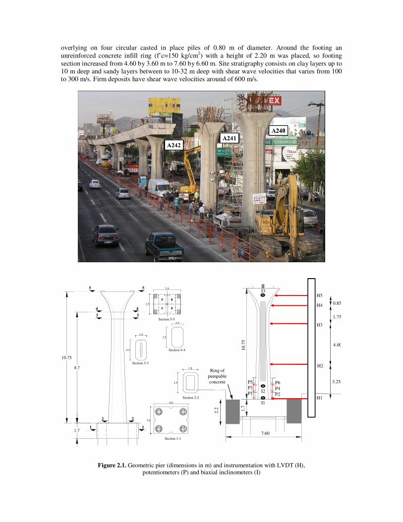
overlying on four circular casted in place piles of 0.80 m of diameter. Around the footing an
unreinforced concrete infill ring (f’c=150 kg/cm2) with a height of 2.20 m was placed, so footing
section increased from 4.60 by 3.60 m to 7.60 by 6.60 m. Site stratigraphy consists on clay layers up to
10 m deep and sandy layers between to 10-32 m deep with shear wave velocities that varies from 100
to 300 m/s. Firm deposits have shear wave velocities around of 600 m/s.
1.7
2.5
1.4
1.8
2.5
3.6
4.6
1 1
2 2
Section 1-1
Section 2-2
Section 3-3
Section 4-4
Section 5-53
4
5 5
4
3
2.5
1.4
2.5
3.4
10.75
8.7
10,7
5
0,5
3
0,9
7,34
1,7
P5
P3
P1
P6
P4
P2H1
H2
H3
H4
H5
0.85
3.25
1.75
4.00
I3
I2
I1
7.60
10.7
5
0.5
3
1.7
2.2
Ring of
pumpable
concrete
Figure 2.1. Geometric pier (dimensions in m) and instrumentation with LVDT (H), potentiometers (P) and biaxial inclinometers (I)
3. TEST PROGRAM
The lateral-loading test consisted of the application of a nearly horizontal load at the top of the pier
while the lateral displacement and tilting of the pier-footing assembly were measured. The first-stage
test was conducted with isolated pier-footing while the second-stage test took place after the
construction of the viaduct was concluded (Fig. 1.2). A 500 t crane was used to apply an increasing
monotonic load up to 56.6 t. An independent steel frame with adequate lateral stiffness was used to set
the LVDT’s to measure the lateral displacement. During the test, this frame was set next to the pier-
footing assembly with proper care to avoid its interaction with the test specimen
Test main goal was to determine the lateral deflection of the pier-footing structural system in the
perpendicular direction to viaduct axis under different lateral loads. With the implemented
instrumentation, deformations for the three piers were defined, the one were the load was applied
(A241) and the two adjacent (A240 and A242) (Fig. 2.1).
The isolated pier test consisted on apply two monotonic tension lateral loads arising from 0 to 24.0 t
(Ti1) and from 0 to 56.6 t (Ti2). Maximum load is less than 25% of design load. Load was applied in a
perpendicular direction to viaduct axis in order to produce a lateral deflection with the crane (Fig. 1.2).
Crane cable had an inclination angle with respect to the horizontal of 28º and 18º for the first and
second load cycles, respectively. For the second-stage test, with the structure concluded, four
monotonic loads were applied with values of 49.0 t (Tc1), 53.7 t (Tc2), 44.0 t (Tc3) y 44.6 t (Tc4).
Cable crane inclination was of 24º for these tests. These loads are less than 10% the design load.
Pier displacements and rotations were measured during the whole load application. For this, pier A241
was instrumented with five LVDT displacement transducers (H), six potentiometers (P) and three
biaxial inclinometers (I) (Fig. 2.1). Piers A240 and A242 were instrumented with five LVDT
displacement transducers and three biaxial inclinometers.
In order to define the structure and soil main frequencies of vibration, ambient vibration test were
conducted with servoaccelerometers arrays.
4. ANALYSIS OF RESULTS
Pier lateral deformation shape was outlined with the values measured by LVDT’s. Fig. 4.1a compares
the lateral deformation profiles of all loads applied of the both stages test for the A241 pier. These
profiles are outlined for horizontal loads of 23.5 and 44 t. Fig. 4.1b compares the same data of lateral
deformation profiles with the normalized displacement and shows that deformation of the structure is
the same in all tests, differing only in the displacements and rotations of the base.
The instrumentation allowed for the acquisition of data to estimate the horizontal and rocking
stiffnesses associated with soil-structure interaction.
First-stage test data, corresponding to the isolated pier (A241), allows estimating the translation (Kt)
and rocking (Kr) stiffness associated with soil-structure interaction (SSI) in the transversal direction.
For Kt estimation, the curves presented in Fig. 4.2a were used. These curves relate the lateral load
with horizontal base displacement recorded for two load cycles. First load cycle (Ti1), which goes up
to 24 t, shows a quasi-linear behavior. On the other hand, second load cycle (Ti2), which goes up to
56.6 t, manifests a trilinear behavior, characterized by two thresholds, one at 15 t and other at 35 t.
Stiffness for each branch are presented on Table 4.1.
For Kr estimation, the curves that relate the base moment and footing rotation were used. These curves
are presented in Fig. 4.2b for the two load cycles. The behavior for both load cycles is quasi-linear for
load values less than 35 t. On the second load cycle, for a load value around 35 t, which corresponds to
a base moment value of 350 t-m, a singularity occurs. This singularity matches the second threshold
defined before, and there is a slope change too. Slope values are presented in Table 4.1.
(a) (b)
Figure 4.1. Lateral deformation profiles of A241 pier for 1st and 2
nd stage under lateral loads of 23.5 and 44 t
0 0.2 0.4 0.6 0.8 1Displacements, in mm
0
10
20
30
40
50
60
Late
ral
load
, in
t
Ti1
Ti2
Fitted Ti1
Fitted Ti2
0.0000 0.0001 0.0002Rotation, in radians
0
100
200
300
400
500
600
700
Mo
men
t, i
n t
-m
Ti1
Ti2
Fitted Ti1
Fitted Ti2
(a) (b)
Figure 4.2. Lateral load-base displacement (a) and moment-rotation (b) curves for A241 pier and estimation of
translation (Kt) and rocking (Kr) stiffnesses
Table 4.1. Experimental values of horizontal and rocking stiffnesses
Stiffness Units Lateral load
< 15 t 15 to 35 t 35 to 57 t
Kt t/m 462,000 90,000 42,000
Kr t-m/rad 6,270,000 6,270,000 4,770,000
Fundamental frequencies for transversal direction from ambient vibration test for 1st and 2
nd stages are
fpier=5.9 Hz and fs=1.4 Hz, respectively. Site dominant frequency is approximated to fsoil=1.08 Hz.
5. THEORETICAL ANALYSIS
The translation and rocking analytical stiffness associated with SSI effects was calculated with the
software DYNA5 (Novak et al., 1995). The soil profile is defined and the group effect on piles is taken in to account. In order to define the piles-footing system stiffness, a direct sum of the pile group
and footing stiffness evaluated separately was performed. Following this consideration, two cases
were assumed: one without ring of unreinforced concrete infill and other considering the contribution
of this ring. Results are shown in Table 5.1 for static and dynamic considerations. Static condition
means non-frequency-dependent, and dynamic values are those that belong to estimation according
with the identified system frequencies that mention in the last section.
Table 5.1
Stiffness Units Foundation without ring Foundation with ring (7.6 x 6.6 m)
Figure 5.1. Comparison of experimental values of the Kt and Kr and the analytical impedance curve of the foundation obtained with DYNA5
Some important aspects from values in Table 5.1 stand out. Differences between static and dynamic
stiffness are practically negligible. In the case of foundation unreinforced concrete ring influence, it is seen that for translation and rocking stiffness values are about 30 and 60 % less when not considering
the ring. Comparing with the experimental values is observed that consideration of the ring is more
appropriate. Fig. 5.1 shows experimental values of the translation and rocking dynamic stiffness and
the analytical curve of the translation and rocking dynamic stiffness of piles-footing system as a
function of frequency obtained with DYNA5. Dynamic stiffness of foundations is frequency-
dependent, such as is shown in Fig. 5.1. In this study a range of frequencies from 0 to 25 Hz is
considered in order to cover the most significant motions involved in the dynamic response of the
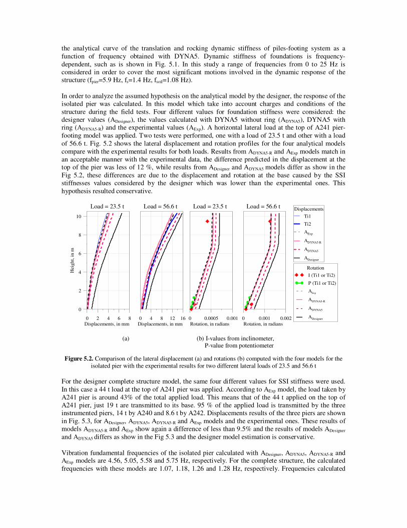
In order to analyze the assumed hypothesis on the analytical model by the designer, the response of the
isolated pier was calculated. In this model which take into account charges and conditions of the
structure during the field tests. Four different values for foundation stiffness were considered: the
designer values (ADesigner), the values calculated with DYNA5 without ring (ADYNA5), DYNA5 with
ring (ADYNA5-R) and the experimental values (AExp). A horizontal lateral load at the top of A241 pier-
footing model was applied. Two tests were performed, one with a load of 23.5 t and other with a load
of 56.6 t. Fig. 5.2 shows the lateral displacement and rotation profiles for the four analytical models
compare with the experimental results for both loads. Results from ADYNA5-R and AExp models match in
an acceptable manner with the experimental data, the difference predicted in the displacement at the
top of the pier was less of 12 %, while results from ADesigner and ADYNA5 models differ as show in the
Fig 5.2, these differences are due to the displacement and rotation at the base caused by the SSI
stiffnesses values considered by the designer which was lower than the experimental ones. This
hypothesis resulted conservative.
0 0.0005 0.001Rotation, in radians
Load = 23.5 t
Rotation
I (Ti1 or Ti2)
P (Ti1 or Ti2)
AExp
ADYNA5-R
ADYNA5
ADesigner0 0.001 0.002Rotation, in radians
Load = 56.6 t
0 2 4 6 8Displacements, in mm
0
2
4
6
8
10
Hei
gh
t, i
n m
Load = 23.5 t Displacements
Ti1
Ti2
AExp
ADYNA5-R
ADYNA5
ADesigner
0 4 8 12 16Displacements, in mm
Load = 56.6 t
(a) (b) I-values from inclinometer, P-value from potentiometer
Figure 5.2. Comparison of the lateral displacement (a) and rotations (b) computed with the four models for the
isolated pier with the experimental results for two different lateral loads of 23.5 and 56.6 t
For the designer complete structure model, the same four different values for SSI stiffness were used.
In this case a 44 t load at the top of A241 pier was applied. According to AExp model, the load taken by
A241 pier is around 43% of the total applied load. This means that of the 44 t applied on the top of
A241 pier, just 19 t are transmitted to its base. 95 % of the applied load is transmitted by the three
instrumented piers, 14 t by A240 and 8.6 t by A242. Displacements results of the three piers are shown
in Fig. 5.3, for ADesigner, ADYNA5, ADYNA5-R and AExp models and the experimental ones. These results of
models ADYNA5-R and AExp show again a difference of less than 9.5% and the results of models ADesigner
and ADYNA5 differs as show in the Fig 5.3 and the designer model estimation is conservative.
Vibration fundamental frequencies of the isolated pier calculated with ADesigner, ADYNA5, ADYNA5-R and AExp models are 4.56, 5.05, 5.58 and 5.75 Hz, respectively. For the complete structure, the calculated
frequencies with these models are 1.07, 1.18, 1.26 and 1.28 Hz, respectively. Frequencies calculated
with models ADYNA5-R and AExp differs from the measured frequency less than 10% whereas the
frequency calculated with ADesigner and ADYNA5 models differs 16 to 24%.
0 0.4 0.8 1.2Displacements, in mm
A-242
2nd StageTc1
Tc2
Tc3
Tc4
AnalyticalAExp
ADYNA5-R
ADYNA5
ADesigner
0 1 2 3 4Displacements, in mm
A-241
0 1 2 3Displacements, in mm
0
2
4
6
8
10
Hei
gh
t, i
n m
A-240
Figure 5.3. Comparison of the lateral displacement (a) and rotations (b) computed with the four models for the
complete structure with the experimental results for lateral loads of 44 t applied at the top of A241 pier
6. CONCLUSIONS
First-stage test results, with isolated pier-footing, show a stiffness variation at a certain point. This
variation could be due to a foundation accommodation and evidences a non-linear behavior of soil-
structure interaction due to contact effects between the soil and the foundation. With these tests was
possible to establish the experimental values of translational and rocking stiffness. Second-stage test,
with the complete structure, experimental responses of the four load cycles were similar among them
and manifest a linear behavior.
In the studied piers, the infill unreinforced concrete ring placed around the footing seems to be
important on the definition of SSI foundation stiffness. According to theoretical results, this ring
provides a larger stiffness to foundation. Furthermore, this ring is expected to be an additional source
of no-linear behavior due to its unreinforced nature.
Considering the experimental foundation SSI stiffness or the ones calculated with DYNA5 taking in to
account the infill ring of unreinforced concrete in the designer model of the structure, consistent values
were achieved between the analytical and experimental results in terms of displacements and rotations.
It suggests that the foundation SSI stiffness considered by the designer, which are smaller than the
experimental ones, produced a more flexible structure. In this study, this assumption was found to be
conservative.
Therefore it is recommended to conduct a field tests program to a more typical isolated piers on soft
soils subjected to lateral design loads. In the test different base conditions should be considered such as the influence of material used to support the footings and to fill the gap between footing perimeter
and the excavation made for its construction. The evaluation of the foundation basis and the lateral
infill characteristics in order to obtain an adequate perform of the pier-foundation system must be
studied too. These studies are justified, given the hundreds of piers that are necessary for the
construction of an elevated viaduct, as those built in Mexico City.
ACKNOWLEDGEMENT This research was funded by Government of State of Mexico. We wish to thank José María Rioboo, Luis
Cabrera and Arturo Padilla who provided the designer models and the structural and geotechnical documentation
required. A special acknowledge to Esther Garcés, Marisol Casas, Alberto Borrego and Carlos Guerra for their
support in the field tests and the technical information of the constructions provided. Authors also thank to
Miguel A. Mendoza, Gerardo Rodríguez, José A Escobar, José Camargo, Navani N Cadena, Irepani A López,
Luis A Ibáñez and Joel Cortes for their invaluable help. A grateful recognition to Raymundo Mondragón,
Ponciano Trinidad, José Rosales and Oscar Rosales for their collaboration during the field tests. The comments
of Santiago Loera and Gerardo Aguilar are well appreciated.
REFERENCES
AASHTO (2002). American Association of State Highways and Transportation Officials, 17th Edition.
ACI (2008). Building Code Requirements for Structural Concrete and Commentary. American Concrete Institute
Standard, ACI 318-08.
Novak M, Sheta M, El-Hifnawi L, El Marsafawi H, El Naggar H, Ramadan O, and El-Sawy K (1995). DYNA5.
Geotechnical Research Centre. University of Western Ontario.
NTCDF (2004).“Complementary Technical Norms for the Design and Construction of Concrete Structures”, and
“Complementary Technical Norms for Earthquake Design” of the Reglamento de Construcciones para el
Distrito Federal”. Gaceta Oficial del Gobierno del Distrito Federal, nº103-BIS, October 6.