U.S. Department of the Interior Bureau of Reclamation Denver, Colorado January 2012 Facilities Instructions, Standards, and Techniques Volume 3-33 Industrial Control Systems (ICS) Including Supervisory Control and Data Acquisition (SCADA) Systems Operation and Maintenance
Transcript
U.S. Department of the Interior Bureau of Reclamation Denver, Colorado January 2012
Facilities Instructions, Standards, and Techniques Volume 3-33
Industrial Control Systems (ICS) Including Supervisory Control and Data Acquisition (SCADA) Systems Operation and Maintenance
REPORT DOCUMENTATION PAGE Form Approved
OMB No. 0704-0188 Public reporting burden for this collection of information is estimated to average 1 hour per response, including the time for reviewing instructions, searching existing data sources, gathering and maintaining the data needed, and completing and reviewing this collection of information. Send comments regarding this burden estimate or any other aspect of this collection of information, including suggestions for reducing this burden to Department of Defense, Washington Headquarters Services, Directorate for Information Operations and Reports (0704-0188), 1215 Jefferson Davis Highway, Suite 1204, Arlington, VA 22202-4302. Respondents should be aware that notwithstanding any other provision of law, no person shall be subject to any penalty for failing to comply with a collection of information if it does not display a currently valid OMB control number. PLEASE DO NOT RETURN YOUR FORM TO THE ABOVE ADDRESS.
1. REPORT DATE (DD-MM-YYYY)
January 17, 2012 2. REPORT TYPE
Final 3. DATES COVERED (From - To)
Implementation Date:
January 1, 2013 4. TITLE AND SUBTITLE
FIST 3-33, Industrial Control Systems (ICS) Including Supervisory Control and Data Acquisition (SCADA) Systems Operation and Maintenance
5a. CONTRACT NUMBER
5b. GRANT NUMBER
5c. PROGRAM ELEMENT NUMBER
6. AUTHOR(S) Bureau of Reclamation Power Resources Office Denver, Colorado
5d. PROJECT NUMBER
5e. TASK NUMBER
5f. WORK UNIT NUMBER
7. PERFORMING ORGANIZATION NAME(S) AND ADDRESS(ES) Hydropower Technical Services Group, Bureau of Reclamation Denver Federal Center P.O. Box 25007 Denver CO 80225-0007
8. PERFORMING ORGANIZATION REPORT NUMBER
FIST 3-33
9. SPONSORING / MONITORING AGENCY NAME(S) AND ADDRESS(ES) Power Resources Office, Office of Policy Bureau of Reclamation Mail Code 86-68450 PO Box 25007 Denver CO 80225-0007
12. DISTRIBUTION / AVAILABILITY STATEMENT Available from the National Technical Information Service, Operations Division, 5285 Port Royal Road, Springfield, Virginia 22161 13. SUPPLEMENTARY NOTES
14. ABSTRACT This document establishes guidance on recommended and required (i.e., subject to onsite reviews) practices for operating and maintaining Industrial Control Systems (ICSs) installed in Reclamation facilities. This guidance is for both operations personnel that use ICS equipment and support personnel that maintain ICS equipment. For the purposes of this document, the ICS includes all equipment within the boundary defined in the System Security Plan. Reclamation ICSs are diverse in size, complexity, technology, and architecture. This document also addresses basic practices that provide a standard framework for the periodic review and improvement of ICS operation and maintenance programs.
15. SUBJECT TERMS Industrial Control Systems, ICS, Supervisory Control and Data Acquisition Systems, SCADA, operation and maintenance, powerplant facilities
16. SECURITY CLASSIFICATION OF: 17. LIMITATION OF ABSTRACT
UL
18. NUMBER OF PAGES
46
19a. NAME OF RESPONSIBLE PERSON Power Resources Office
a. REPORT
b. ABSTRACT
c. THIS PAGE
19b. TELEPHONE NUMBER (include area code)
303-445-2922 Standard Form 298 (Rev. 8/98)
Prescribed by ANSI Std. 239-18
U.S. Department of the Interior Bureau of Reclamation Power Resources Office Denver, Colorado January 2012
Facilities, Instructions, Standards, and Techniques Volume 3-33
Industrial Control Systems (ICS) Including Supervisory Control and Data Acquisition (SCADA) Systems Operation and Maintenance
Disclaimer This written material consists of general information for internal Bureau of Reclamation operations and maintenance staff use. Information contained in this document regarding commercial products or firms may not be used for advertising or promotional purposes and is not to be construed as an endorsement or of any product or firm by the Bureau of Reclamation.
iii
Table of Contents Page
1. Introduction ............................................................................................... 11.1 Purpose ............................................................................................ 1 1.2 Scope ............................................................................................... 1 1.3 Document Organization .................................................................. 2 1.4 Reclamation Standard Practices ...................................................... 3 1.5 Effect of Section Headings ............................................................. 4 1.6 Description of Industrial Control Systems ...................................... 4
2. Power Operations and Maintenance Reviews........................................... 5
6. Operations ................................................................................................. 10 6.1 Control Consoles and Displays ....................................................... 10 6.2 Equipment and Facility Monitoring ................................................ 11 6.3 Control Modes and Unit Controls ................................................... 11
8. Technical Support Documentation and Training ...................................... 23 8.1 Documentation ................................................................................ 23
8.2 Documentation Storage ................................................................... 26 8.3 Training ........................................................................................... 26
8.3.1 Operations Training ............................................................ 27 8.3.2 ICS Support Staff Programming and Software
Engineering Training .......................................................... 28 8.3.3 System Administrator Training........................................... 28 8.3.4 Security General Awareness Training ................................ 29
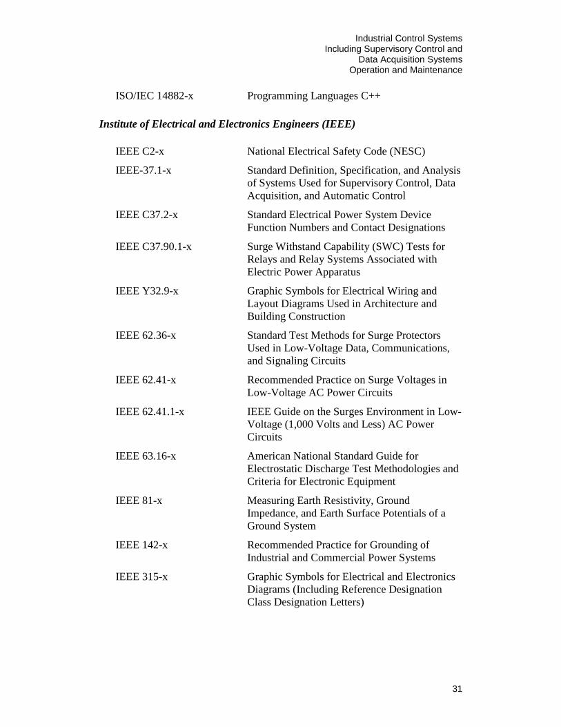
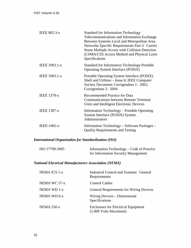
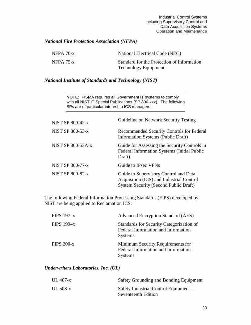
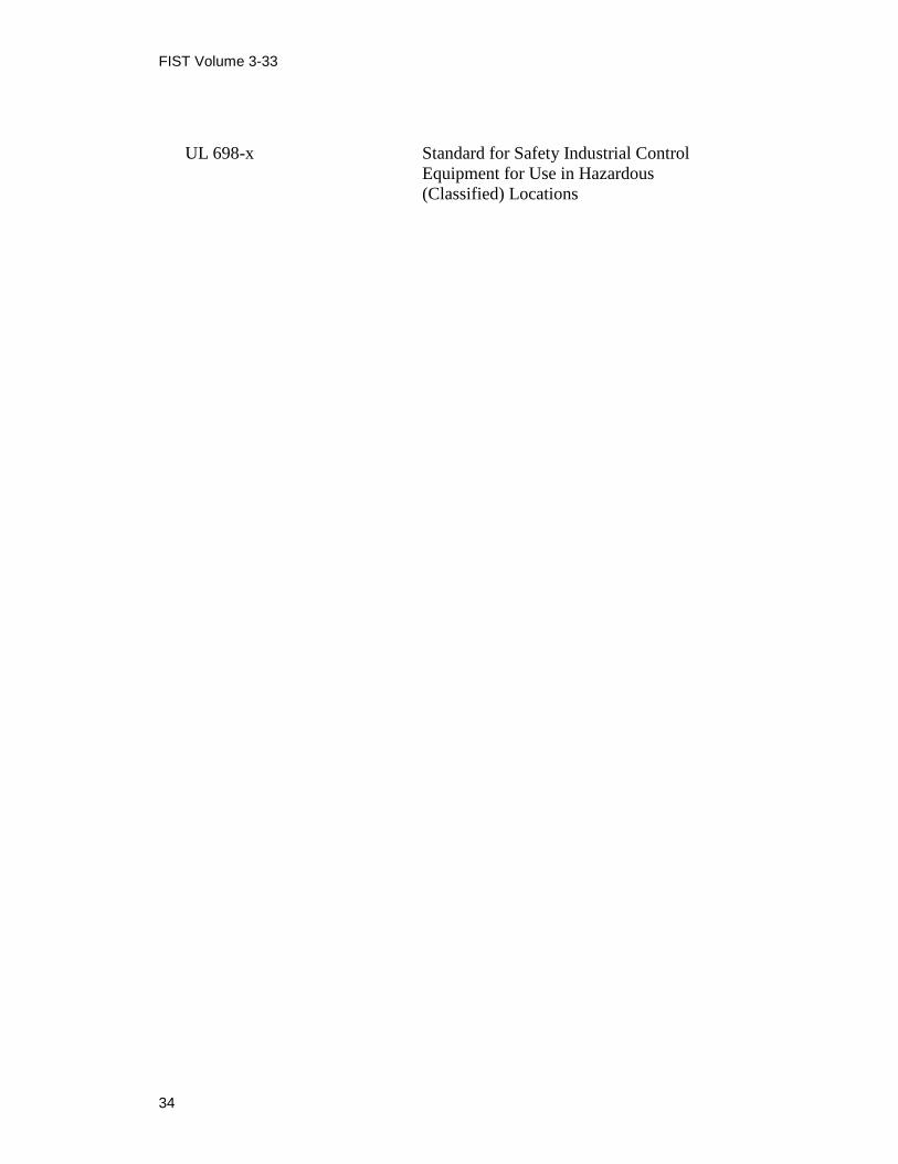
8.4 Standards and References ............................................................... 29
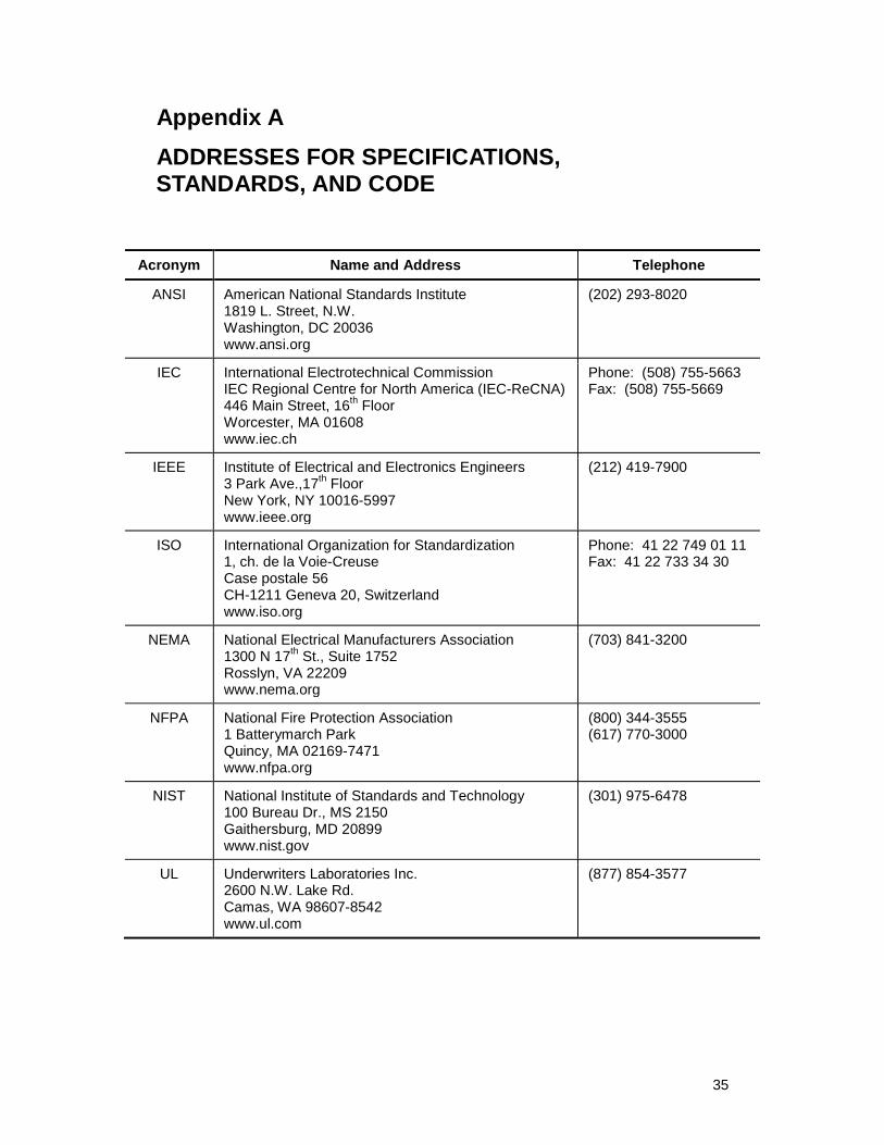
Appendix A – Addresses for Specifications, Standards, and Code ................ 35
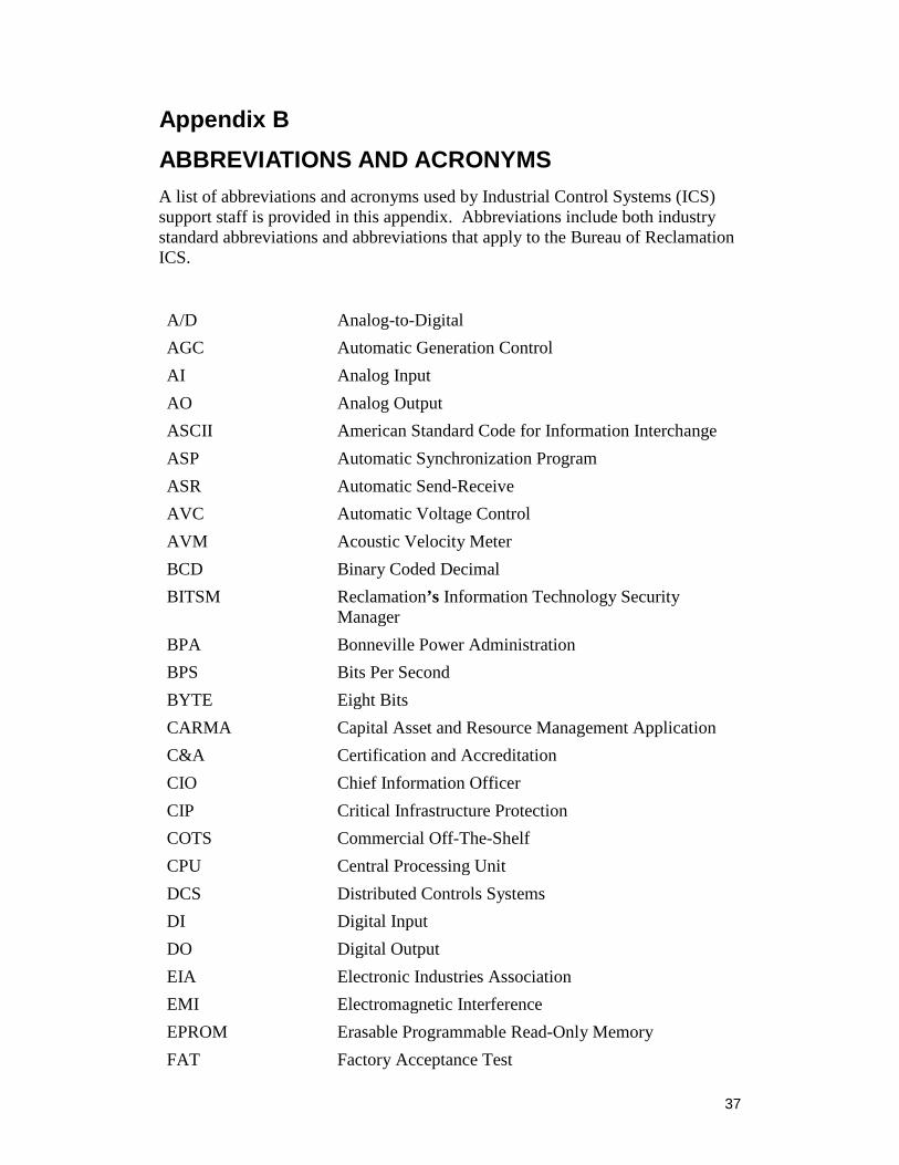
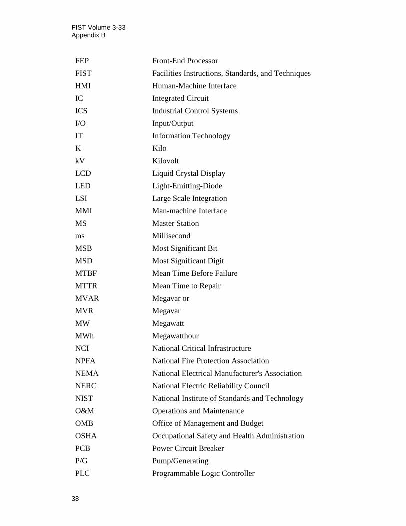
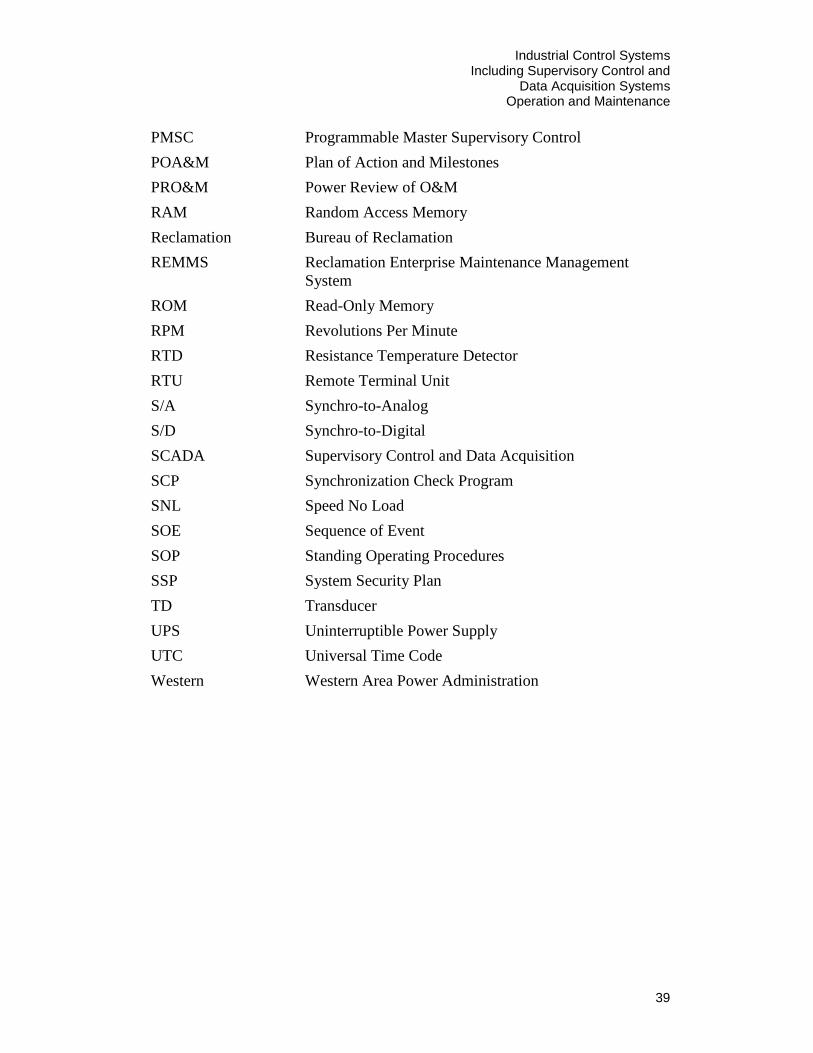
Appendix B – Abbreviations and Acronyms .................................................. 37
Industrial Control Systems Including Supervisory Control and
Data Acquisition Systems Operation and Maintenance
1
1. Introduction The Bureau of Reclamation (Reclamation) has constructed more than 600 dams and reservoirs in 17 Western States since its establishment in 1902. As the largest wholesale provider of water in the Nation, we serve more than 31 million people and provide irrigation water for 10 million acres of farmland. Reclamation is also the second largest producer of hydroelectric power in the Nation. Our 53 powerplants generate more than 42 billion kilowatt-hours annually.
Reclamation has used Industrial Control Systems (ICSs), which include Supervisory Control and Data Acquisition (SCADA) systems, for more than 35 years to monitor and control water and power operations at our dams, canals, pumping plants, powerplants, and other related facilities.1
These ICSs have evolved from the early, dedicated systems based almost entirely on custom, proprietary hardware and software to modern network-based systems comprised of commercial off-the-shelf (COTS) hardware and operating systems, which support a mixture of COTS and custom-developed software. Our ongoing facility modernization programs have resulted in using new technologies that increase the level of automation and expand equipment-monitoring capabilities. ICSs are described in detail later in this document.
Reclamation currently operates, maintains, and performs security accreditation for approximately sixteen ICSs (SCADA systems); including four systems designated as National Critical Infrastructure Information Systems.
1.1 Purpose
This document establishes guidance on recommended and required (i.e., subject to onsite reviews—see sections 1.4 and 2.0) practices for operating and maintaining ICSs installed in Reclamation facilities. This guidance is for both operations personnel that use ICS equipment and support personnel that maintain ICS equipment. For the purposes of this document, the ICS includes all equipment within the boundary defined in the System Security Plan (SSP) (see section 1.6).
1.2 Scope
Reclamation ICSs are diverse in size, complexity, technology, and architecture. ICSs designed solely to control irrigation systems or other water projects can apply the recommended practices where appropriate for these facilities. Therefore, this Facilities Instructions, Standards, and Techniques (FIST)
1 SCADA systems have also been referred to as Programmable Master Supervisory Control
(PMSC) systems within Reclamation.
FIST Volume 3-33
2
Volume 3-33, Industrial Control Systems (ICS) Including Supervisory Control and Data Acquisition (SCADA) Systems Operation and Maintenance, addresses basic practices that provide a standard framework for the periodic review and improvement of ICS operation and maintenance (O&M) programs. This FIST addresses Reclamation ICS O&M practices as follows:
• Addresses operating and maintaining Reclamation ICSs used to control and monitor Reclamation-owned power equipment such as powerplants, pumping plants, switchyards, and other related power facilities. It will not address ICS systems that operate Reclamation facilities that are not owned by Reclamation.
• Does not cover the specific operational requirements for the water and electrical power systems controlled and monitored using an ICS. Refer to the Standing Operating Procedures (SOPs) or technical equipment manuals for the particular site to obtain this information.
• Describes some basic training requirements for operators. However, more detailed training requirements that relate to ICS operations are addressed and reviewed from an operations perspective in other documents (see FIST Volumes 1-1, 1-2, and 1-11). It is important to ensure control center and powerplant operators have the skills necessary to operate the ICSs used to control their facilities.
• Is not a reference for the physical, information technology (IT) or any other regulatory security requirements that apply to Reclamation ICSs. It is important to consider security requirements during all phases of an ICSs life cycle. However, no effort will be made to cover specific security requirements within this document. For additional information concerning security issues, see section 4.
1.3 Document Organization
This FIST is organized into four sections:
The “Management” section covers key management practices for the operation and maintenance phase of ICSs.
• The normal lifecycle of an ICS includes the following phases:
o Planning – Planning is the process where the needs of a new system or an incremental change to an existing system are determined and how the change is to be accomplished. Planning also is used to identify how and when the operational and maintenance needs are determined for an operational system.
Industrial Control Systems Including Supervisory Control and
Data Acquisition Systems Operation and Maintenance
3
o Design – Design is where the planned system and scope of the system are identified, so that the system can be modified or procured.
o Procurement/Construction/Testing –
Procurement is how the hardware and software for a system or update is obtained.
Construction is where a new system or major maintenance evolution is put into place.
Testing is to make sure a new system works as intended or a change to a system is verified as effective before being implemented on the operational system.
o Commissioning – Commissioning is the process of ensuring that all systems, components, and software of an ICS are designed, installed, inspected, tested, operated, and maintained according to the operational requirements, prior to being handed over to the operations and maintenance staff.
o Operations and Maintenance – Primary state of an operational system, with parts of the hardware and software possibly moving into and out of the other parts of the cycle to correct problems or implement manufacturer identified corrections.
o Decommissioning/Retirement – The system has been replaced, or a part of the system has been replaced or superseded; the equipment or software is shutdown or removed from service, prepared for disposal, and then disposed.
Several of these phases are covered in this document, at least in part, but the primary focus is on the operations and maintenance phase of an ICS.
The “Operations” section will cover standards for operation of the ICS.
The “Maintenance” section covers general maintenance, preventative maintenance, trouble-shooting, and response to major incidents or failures.
The “Technical Support Documentation and Training” section covers documentation and training requirements for effective technical support.
1.4 Reclamation Standard Practices
FIST procedures, practices, and schedules that appear in black bold and bracketed text are considered Reclamation standard practice. FIST procedures, practices, and schedules that appear in red bold and bracketed text are related to compliance
FIST Volume 3-33
4
issues, such as safety (Occupational Safety and Health Administration [OSHA]) or reliability (North American Electric Reliability Corporation [NERC]) and cannot be varied from.
1.5 Effect of Section Headings
Section headings or titles appearing in this document are inserted for convenience only and must not be construed as interpretations of text or a standard practice.
1.6 Description of Industrial Control Systems
In this document, the term “ICSs” includes systems called “SCADA systems” and Distributed Controls Systems (DCSs). ICSs refers to computer-based systems that provide automated equipment control and perform the data collection and processing required to support those control functions. Some Reclamation ICSs do not perform any control functions but solely are dedicated to collecting data. Other remote independent systems require operators to supervise actual equipment control.
Primarily, ICS software includes all software for remote and local automated equipment control and for collecting and processing data to directly support control functions. In addition, the ICS software facilitates data collection and control as required by external entities such as Western Area Power Administration (Western), Bonneville Power Administration (BPA), other Federal agencies, other interconnected system operating authorities, local irrigation districts, and local power customers. ICS software typically includes:
1. Real-time data acquisition software
2. Report generation software
3. Real-time unit and plant control software
4. Standard control software (logic controls, feedback controls)
5. Database software
6. Communication software
7. Human-machine interface (HMI) software for the display of real-time, alarm, and trend-data and for the control of the units and plant
8. A variety of software development tools and system configuration tools
For each ICS, it will be important to determine the boundary of that particular ICS. Typically, historical archiving, maintenance management, and water
Industrial Control Systems Including Supervisory Control and
Data Acquisition Systems Operation and Maintenance
5
scheduling functions are not considered part of the ICS. In the past, Reclamation ICS support normally extended to a remote terminal unit (RTU) or other device such as a programmable logic controller (PLC) that supports data acquisition and control for a particular turbine/generator, switchyard, or other powerplant equipment. As plants begin to install intelligent devices at the local equipment level, the RTU functions are being distributed among a set of computerized devices that are no longer purchased as part of the plant ICS.
The boundary for the ICS should include all ICS equipment within the boundary used for ICS Assessment and Authorization (A&A—formerly referred to as Certification and Accreditation), which is required for authority to operate by Reclamation. This boundary can include a diversity of equipment depending on the network configuration, but is ultimately defined in the System Security Plan as stipulated by the A&A. Note that the local intelligent devices are subject to similar requirements as the ICS itself. They require many of the same safeguards to ensure proper operation and maintenance goals are achieved. Roles and responsibilities with respect to the ICS are described in section 5.1 below.
2. Power Operations and Maintenance Reviews O&M standards, FIST procedures, practices, and schedules that are in bold and bracketed are considered minimum requirements. Meeting these requirement is to be verified at power facilities during onsite reviews performed under the Power Review of O&M (PRO&M) process as defined by Directive and Standard FAC 04-01. Reviews of ICSs present additional challenges for the PRO&M process. Sensitive information is to be protected during the review process. ICSs can involve multiple powerplants with a centralized control center that may or may not be located at a Reclamation powerplant. Contact the Power Resources Office at 303-445-3565, or visit the Web site at http://intranet.usbr.gov/~hydrores/for more information.
3. Limitations This FIST summarizes operations and maintenance standards for ICSs and directs the reader to related references. It should not be the sole source of information used in conducting maintenance activities. Other references, training, and work experience also are necessary to fully understand and carry out the recommended operations and maintenance activities.
4. Security All Reclamation ICSs are subject to the requirements contained in the Office of Management and Budget (OMB) Circular A-130 (Appendix III, as amended) and the Federal Information Security Management Act (FISMA) of 2002 (44 United
FIST Volume 3-33
6
States Code [U.S.C.] Section (§) 3541). Beginning with the passage of the Energy Policy Act of 2005, a number of new Federal cyber security requirements became effective. These new requirements, identified in the NERC Critical Infrastructure Protection (CIP) Standards, are directly applicable to a subset of Reclamation cyber systems, where those systems specifically support bulk electric system (BES) reliability. ICS security requirements are critical to operate and maintain Reclamation ICSs properly. The primary goal of ICS security reviews is to protect the ICS rather than to address system proper operation and maintenance.
The goal of this FIST is not to duplicate those requirements for physical and IT security addressed in existing ICS security plans and policies, but rather to document requirements and procedures to properly operate and maintain Reclamation ICSs. When the operations and maintenance practices identified in this FIST have been appropriately addressed, documentation of those practices can be used to satisfy relevant security requirements.
Information technology security requirements for ICSs are addressed through implementing Federal requirements as directed and interpreted by Reclamation’s Chief Information Office (CIO). Standards have been developed for a variety of security controls, including both physical security and computer security requirements. Some of the key requirements include those published by:
1. The National Institute of Standards and Technology (NIST) – Specifically, Special Publication 800-53 addressing the security of Federal information technology systems.
2. Interior’s IT Security Policy Handbook establishes the minimum requirements for all IT systems operated by Interior. The document, entitled Current IT Security Policy Handbook, can be found at http://intra.usbr.gov/usbrit/security/.
3. The NERC Reliability Standards – Specifically, the NERC CIP Standards. These standards, while they are applicable to many ICSs, primarily are intended to address the security requirements of ICSs controlling power facilities.
It should be noted that these security standards (with the exception of the NERC Standards) typically focus on requirements for administrative IT systems and their applications. Applying these requirements to the security of ICSs and ICS applications is to be done carefully so as not to compromise the operational usefulness, integrity, and reliability of the ICS and its associated applications. Due to the critical real-time operational requirements of ICSs, some flexibility in addressing the security controls in the standards is sometimes necessary to support their operation. For more information, please contact Reclamation’s IT Security Policy Office:
Industrial Control Systems Including Supervisory Control and
Data Acquisition Systems Operation and Maintenance
7
IT Risk and Portfolio Management Division Mail Code 84-21200 Denver, Colorado
The IT Security Policy Web site also provides additional information on directives and standards, accreditation, and training: http://intra.usbr.gov/usbrit/security/.
5. Management Effective ICS operations and maintenance programs depend on key management practices that include: 1) roles and responsibilities, 2) planning, and 3) monitoring. This “Management” section covers the general requirements for ICSs. It is important to note that the scope of the requirements varies with size and criticality of the ICS.
5.1 Roles and Responsibilities
Responsibilities for ICS operations and maintenance are to be formally assigned and documented. Suggested key roles and responsibilities are listed here:
1. Reclamation’s Commissioner formally authorizes the operation of ICSs, based on their meeting minimum IT security requirements as established in Federal law.
2. Reclamation’s Chief Information Officer is responsible for certifying the security of ICSs and recommending investments for information technology used in ICSs.
3. ICS executive owners (e.g., regional directors) ensure systems support Reclamation’s mission and are operated and maintained in compliance with relevant regulations.
4. ICS business owners (e.g., area managers, power managers, operations managers, etc.) are responsible for providing guidance on mission requirements, support, and resources (funding and staff) for ICS operations and maintenance activities.
5. ICS project manager’s plan and implement operations and maintenance programs for ICSs to support mission goals and objectives, monitor performance, and provide training for system users and support staff.
6. ICS support personnel (system managers, ICS engineers, ICS programmers, technicians, etc.) are responsible for performing system replacements, software and equipment maintenance, system administration, communications support, and system health monitoring.
7. ICS security managers are responsible for identifying, configuring, and managing ICS security safeguards that include day-to-day reviews to ensure security controls are working and technical advice on security documentation, policy, and issues.
8. ICS users (e.g., operators, controllers, dispatchers, engineers, etc.) are responsible for following ICS operating procedures and criteria contained in SOPs and for notifying system support staff when ICS problems are observed.
5.2 Planning
Planning is required to manage ICSs effectively in the operations and maintenance phase of their lifecycle. [ICSs that are classified to be major Reclamation systems or ICSs as identified by Reclamation policy must have system plans to manage operational costs, risks, and performance results.] Other ICSs should be grouped within larger systems for efficient planning. [Business cases and maintenance plans must be developed and reviewed annually or as directed by policy. Contingency plan tests also must be performed on a periodic basis. Assessments and Authorization, as required by Interior’s IT Security Policy Handbook, includes reviews of contingency plans, configuration management plans, and ICS security plans.]
1. [A business case for the ICS (e.g., see OMB Circular A-11, Exhibit 300) must be developed for the annual budget formulation and investment review process.] The business case planning process is a long-range justification and report on ICS O&M costs, mission value (to support mission performance goals and measures), security costs and compliance status, inclusion in agency target enterprise architecture, risk management, and cost/schedule performance.
2. [Annual maintenance plans for ICS, including revisions and upgrades, shall be developed and then coordinated with plant operations and maintenance staff.] Reclamation’s Capital Asset and Resource Management Application (CARMA™)2
3. [A configuration management plan is required to: define the criteria and approval procedure for changes to an ICS, inventory the managed components, describe the change process, and assign responsibilities.] See Directive and Standard IRM 08-17.
should be used when possible to implement the plan. ICS maintenance procedures entered into CARMA™ should be reviewed for sensitivity and handling requirements; refer to Reclamation Manual Directive and Standard SLE 02-01.
2 Formerly, Reclamation Enterprise Maintenance Management System (REMMS).
Industrial Control Systems Including Supervisory Control and
Data Acquisition Systems Operation and Maintenance
9
4. [A contingency plan must be developed to identify responsibilities, resources, and procedures for response and recovery from a variety of failures and disaster scenarios.] Examples of failure contingencies include station power failure, failure of particular elements of the ICS, or loss of the ICS from fire or flooding hazards. ICS contingency plans should consider operating with a backup control center if required. Contingency plans should be developed and tested with ICS operations personnel participation. ICS contingency plans should be referenced in the Continuity of Operations Plans for the facility where the ICS is located. Refer to Interior’s IT Security Policy Handbook for additional information.
5. [An ICS security plan must be developed to identify assigned responsibilities and the security controls implemented to protect the system.] Refer to Interior’s IT Security Policy Handbook for additional information.
5.3 Monitoring
Managing an ICS’s O&M phase requires monitoring costs, schedule, safeguards, and how well the system meets stakeholder and mission needs. Monitoring of planned maintenance versus actual improvements is performed periodically and on an annual cycle when business cases and maintenance plans are developed.
1. [Major ICSs are required to monitor and report system cost, schedule performance, and conduct an operational analysis periodically as required by policy.] The operational analysis is a standard methodology to assess and quantify the system’s value in supporting mission goals and objectives (e.g., see OMB Circular A-11, Exhibit 300).
2. [An Internal Control Review is required per Reclamation policy for ICSs.] Identified deficiencies must be evaluated, and a corrective action plan must be developed and reported on in the system’s Plan of Action and Milestones (POA&M). See Interior’s IT Security Policy Handbook.
3. [ICS contingency plans, incident response plans, and recovery plans must be exercised as required by Reclamation policy.] Reports of exercises are required. See Interior’s IT Security Policy Handbook.
4. Recommendations identified during onsite reviews conducted under the PRO&M program for ICS operations and maintenance are to be evaluated, actionable improvements must be planned, and status must be reported at annual regional Reclamation Power O&M meetings until completed.
FIST Volume 3-33
10
6. Operations The most important goal for any ICS is to provide operations staff with a tool that allows them to efficiently and reliably monitor and control their plant and facility equipment under normal conditions. This section provides general requirements for normal operations tasks when the ICS is functioning properly and no problems or failures exist. Section 7 discusses tasks associated with identification and repair of failures. Therefore, this section focuses on the consoles, displays, plant equipment monitoring, controls, and other normal operations requirements.
A particular ICS’s performance normally is defined in the original design specifications. However, differences from those specifications do occur, and those differences can be found in design updates or “as-built.” The current documentation for the system is the most reliable source for ICS performance. Please refer to those documents when addressing any system performance issues.
Training for operations and ICS support personnel is described in section 8.3.
6.1 Control Consoles and Displays
The primary interface between the operator and the ICS is via control consoles and various types of displays. The control consoles allow the operator to input commands and data to the ICS as well as to provide the operator with the status of the powerplant and facility equipment. Displaying data is the most critical element of the consoles. Critical functions include:
• Display of real-time data
• Operator command interface to control equipment and processes
• Data input capabilities
• Screen navigation tools
As the consoles and displays are key technical components for “supervisory control,” normal performance characteristics should be reviewed. Characteristics that should be reviewed include: reliability, ease of use, visibility or clarity, effectiveness, and training on modifications or revisions to consoles and displays. Large displays such as mimic boards or panel displays may be used for system overviews, video monitoring for security, and access to local news and weather conditions. Displays, control consoles, and input devices function as operators need; they are maintained, and losses of visibility of displays are to be corrected in a timely manner.
It is recommended that redundancy be provided where possible, so that a single display failure can be tolerated and still leave the operator able to view system
Industrial Control Systems Including Supervisory Control and
Data Acquisition Systems Operation and Maintenance
11
data and perform controls. Multiple consoles and/or multiple view terminals should be provided as necessary to maintain operator functions through display equipment failures.
System overviews and menus should be provided to allow the operator to navigate easily through the input options. Input devices such as console cursor controls (trackball, mouse, etc.) must be provided to perform screen control and input selection. Data is entered with keyboards. Refer to Section 8.4, Standards and References, for additional information.
6.2 Equipment and Facility Monitoring
Monitoring equipment and facility status is a critical element of all ICSs. If the operator is given inaccurate status information, equipment misoperation could result, disrupting key processes such as power generation and water releases. Data reliability and refresh rates from plant equipment and generators should be maintained at an adequate level. Reliability of the ICSs that support powerplant operations at National Critical Infrastructure (NCI) sites, which include Hoover, Grand Coulee, Glen Canyon, and the Central Valley Project (Folsom and Shasta), should be maintained above 99.5 percent (%) on average for normal operations. This is approximately 44 hours of down time in 1 year. Reliability of the ICS may be defined in a variety of ways, depending on the system architecture. However, reliability goals should relate to the ability to provide critical operations support. [Reliability goals should be set for all systems.] This may depend on the critical nature of the controls, or the original system specification goal may be used. Information about reliability should be calculated and recorded so that corrections can be made if the reliability reaches unacceptable levels.
Refresh rates for the data also are important. [For ICSs that support powerplant operations, the data display for the operator always must reflect any change in status within a reasonable period as required by the system design specifications.] Most ICSs within Reclamation require data updates to the operator to occur within a maximum of 2 to 4 seconds.
The quality of status data always should be provided to the operator. Data quality monitoring should include failure conditions (not being updated), alarm conditions, and out-of-range conditions as a minimum. Data failures should be tracked and time tagged.
6.3 Control Modes and Unit Controls
[The capability to override ICS controls must be provided at the unit controls for a particular generator or at the local controls for any type of equipment.] This feature is provided by a control switch such as the unit control, mode selector switch, or the “43CS” selector switch. The 43CS has three switch
FIST Volume 3-33
12
positions or modes: Manual, Local Automatic, and Supervisory. In addition, where a system is digital, a physical 43CS switch is required to allow the generator and its ICS to be separated from the plant or system ICS. [Where a system is fully digital, a physical means of switching the machine to local automatic shall be provided to prohibit the plant or system ICS from causing the machine ICS to operate.] Also, see Section 6.8, Special Operating Procedures.
6.3.1 Manual This mode disables all ICS controls. In this mode, only manual controls can be performed from the control board or near the local equipment.
6.3.2 Local Automatic This mode provides for automatic controls locally for the generator or other plant equipment. For example, the ICS may be used to start a generator or a pump. For some sites, the generator or other equipment also may be controlled using equipment external to the ICS such as relays designed to perform start or stop functions. A local display or panel may be used to allow the operator to initiate the local control functions. No remote control of the generator from a control center or any other remote control room is allowed in this mode.
6.3.3 Supervisory This mode allows the generator or other equipment to be controlled remotely by an operator located at a control room or initiated by control strategy resident within the system application software. All the ICS controls provided can be performed by the remote operator. Manual or local automatic ICS controls are no longer possible in this mode (with the exception of emergency shutdown (86) or headgate close control).
The Standing Operating Procedures for the facility should describe how to use these modes. In addition, the SOPs should note if notifications are required before or after changing the status of the control switch.
6.4 Controls and Applications
[The ICS must provide the operator with the control capabilities necessary to operate the facility.] The control capabilities may include manual operation where applicable. Direct control of equipment such as pumps, breakers, valves, and gates should be provided in a way that allows the operator to perform control tasks reliably, efficiently, and safely. The operator should not use ICS control when the equipment status is questionable. Automatic controls always should be disabled when inputs are questionable and cannot be observed by a reliable source.
Industrial Control Systems Including Supervisory Control and
Data Acquisition Systems Operation and Maintenance
13
Software applications support requirements for controlling equipment such as startup, shutdown, and set point controls (generation, voltage, and flow). Software applications also may support power system control, power system reliability, water system scheduling, and power system scheduling as required. Each system should identify what controls it considers critical. Such controls could include: operation of gates and valves to maintain water delivery, gate control setpoints, generator set points, distribution of automatic generation control, etc. In addition, the frequency of testing of those critical controls should be established. [The critical controls will be tested on their defined frequency.] The controls should be configured to provide the operator with final responsibility for the reliability and safety of the controlled facilities. For Reclamation ICSs that provide powerplant set point controls (generation and automatic voltage), critical features including minimum response requirements should be tested when changes in plant configuration take place.
[Powerplant set point controls must allow governors to respond properly during a frequency disturbance on the power system. Automatic voltage control, as well as facility level voltage control systems or loops, must allow for proper voltage regulator response during power system disturbances.] These controls should not negate the unit’s response to system voltage and frequency deviations during a disturbance, unless it is to keep the unit within its safe operating range. Generally, critical controls should be checked at least every other year.
6.5 Alarms and Event Recording
An alarm system should be provided to display alarm conditions that occur within the plant equipment. The alarm system should allow setting, acknowledging, and clearing alarms. [Operators must be trained to respond to an alarm and what actions are to be taken.] In some cases, methods to disable alarms will be provided to override nuisance alarms. [The cause that requires an alarm to be disabled must be addressed on a timely basis.] The ICS should provide the ability to track overridden alarms.
Every effort should be made to address alarms as they occur as well as to avoid setting alarms that do not require operator attention. ICS staff should work closely with maintenance engineers to minimize the number of alarms presented to the control room operator. A separate maintenance network may be a good option to allow adequate information for engineering purposes while preserving the security and operability of the ICS.
The ICS and management will record significant equipment alarms, events, and ICS changes in a log. The ICS should use time tags for both alarms and events and use a satellite or Global Positioning System clock for time tag accuracy. Error logging and time tagging should use the Universal Time Code (UTC) where practical. In addition, consideration should be made to using universal time for
FIST Volume 3-33
14
the system such that any system covering multiple time zones should use one standard, uniform time across the entire system.
Sequence of Event (SOE) recording should be possible with the ICS. SOE recordings may be an aid to unexpected events investigators in determining what caused an event. See section 7.6 and FIST 6-3, Unexpected Event Reporting. The Regional Power Office or Power Resources Office should be consulted to determine the requirements, if any, for SOE for any power-related unit, plant, or system ICS.
6.6 Shift Change
The ICS should support all requirements for operator shift changes. The ICS should provide log in/out procedures and, if possible, clear previous shift preference settings and initiate settings for the new shift. No loss of data, alarms, or other special conditions should occur during a shift change. Information from previous shifts that a new shift requires should be retained and not lost during the shift change. The exchange of information between operators during the shift change should be accurate and clear.
6.7 Daylight Saving Time
The ICS should support changes to and from daylight saving time where applicable. The time change should occur at the prescribed time, and all ICS features should continue to operate properly with the new time setting. Ensure that there is no loss or overlap of data. All schedule features and time tagging features should adjust properly when the time change occurs. If manual intervention is necessary to perform the time change, then those procedures should be documented.
6.8 Special Operating Procedures
The ICS should provide a visual tag to indicate any special condition for the operator during special operations associated with facility equipment. Any condition that requires physical tagging of equipment should be supported, including clearances, hot line orders, and special conditions. [The visual tags must provide a visual indication of the condition for the operator, are in addition to the actual equipment tags, and are not used to provide the actual lockout features.] It is important that the tagging features are used properly, so that the current condition is indicated to the operator. See FIST 1-1 for additional information regarding the Hazardous Energy Control Program and ICS tagging.
Lockout and tagout conditions for equipment always should be coordinated so that no automatic ICS operations can occur during these conditions. Isolating the equipment using the “43CS” control switch should be incorporated into the
Industrial Control Systems Including Supervisory Control and
Data Acquisition Systems Operation and Maintenance
15
switching orders. Switching to manual or local automatic may allow data to be transmitted from the unit or equipment to the ICS but should preclude any data being transmitted to the unit from the ICS. If status of equipment can be monitored safely during outage conditions, the ICS should provide the operator with that status. The operator should be provided with an indication of all special condition tags if they affect ICS operations.
7. Maintenance There are issues that should be considered when maintaining Reclamation ICSs. Every effort should be made to avoid failures by performing: 1) general maintenance, 2) proper system monitoring and health checks, and 3) recommended preventive maintenance. When failures occur, sound methods of trouble-shooting and performing repairs should be used. Contingency plans and backup/recovery procedures should be in place to recover from failures quickly.
Consider when and how maintenance is performed and what the impact of the maintenance might be to the system being operated. Taking an outage when maintenance is performed that will place key capabilities of the system temporarily out of service should be scheduled when it will have the least impact and when staff can be available to manually operate the controlled facilities if necessary.
7.1 General Maintenance
FIPS-200, Minimum Security Requirements for Federal Information and Information Systems, mandates the use of security controls defined in NIST SP 800-53, Recommended Security Controls for Federal Information Systems. Six controls are defined in the maintenance family of the 800-53 security controls catalog: System Maintenance Policy and Procedures, Controlled Maintenance, Maintenance Tools, Remote Maintenance, Maintenance Personnel, and Timely Maintenance. Therefore, the maintenance recommendations provided in this FIST may be used to satisfy the NIST 800-53 requirements. The recommendations provided are specific to Reclamation ICSs.
[Contracted maintenance services and procedures for ICSs, including remote maintenance processes and practices, must be thoroughly documented.] The use of these services is particularly sensitive for ICSs, typically due to the isolation of the systems and considering the importance the system has when determining to use these services. Remote maintenance processes and practices may require additional security considerations. [The protection measures, mitigation activities, and safeguards that are used for remote maintenance processes and practices for equipment that is part of the ICS shall be documented and enforced.]
FIST Volume 3-33
16
7.1.1 Maintenance Log [A maintenance log for the ICS always must be maintained.] The type of maintenance log (e.g., physical or electronic) and where it is kept (e.g., at each site or at a central location) is to be determined by the system manager. The maintenance log should outline all maintenance activities performed on the system. The record should include, as a minimum, the date of the activity, the responsible party, a brief description of the activity performed, and a list of system component(s) affected. Maintenance logs may be combined with a version control function required to coordinate system upgrades as desired. For more information, see Section 7.5, Configuration Management and Backup/Restore.
7.1.2 Physical Plant Maintenance Requirements
7.1.2.1 Environmental Controls and Fire Protection The environmental controls for the ICS should be checked annually for proper operation and maintained per requirements set by the manufacturer. Operating an ICS at high temperatures can degrade the computer equipment. Cooling systems should be maintained in good condition, and ICS equipment should be maintained at environmental conditions that meet the recommended limits set by the manufacturer.
Fire protection systems should be provided for ICS equipment and maintained per manufacturer requirements. The operability of any fire protection system should be verified at least annually. The proper class of fire retardants should be employed to ensure that fires can be extinguished while minimizing shock hazards and ICS equipment damage. Refer to the National Fire Protection Association (NPFA) in the standards and reference list.
Storage areas should provide appropriate environments and fire protection for the documents and equipment they contain. The ICS and storage areas should be kept clean and orderly and free of unnecessary hazards.
7.1.2.2 Plant Conditioning/Wiring Issues ICSs require proper interface to the powerplant to operate correctly. All transducers shall be functional, and calibration must be maintained. [ICS transducers shall be calibrated and tested on a cycle consistent with FIST 4-1B] It is recommended that all transducer inputs be checked at least once every 3 to 5 years to verify accuracy. [Calibration of transducers, which have a critical nature of the input, shall be documented at least as to the setting found, setting established, and time and date of calibration.]
[Functionally test all ICS control, protection, and alarm circuits, including all control-related, protection-related, alarm-related, and other critical inputs and
Industrial Control Systems Including Supervisory Control and
Data Acquisition Systems Operation and Maintenance
17
outputs and all status inputs, upon commissioning and every 2 years thereafter.] However, it is recommended that critical alarm inputs be checked annually.3
Digital communications to intelligent subsystems such as digital governors, digital relays, flowmeters, and energy meters should be monitored for errors. The monitors should be used to detect performance problems as soon as possible.
Wiring between the plant transducers and sensors should be maintained in good condition. [All wiring and cables, including network cables, shall be legibly labeled.] All wires and cables must be terminated properly. Cable should be confined to trays, conduit, and raised floor areas. Where practical, electric power provided to plant conditioning inputs (status inputs to the SCADA) should be uninterruptable to improve the likelihood that critical status information will be available under various failure scenarios.
7.1.2.3 Equipment Power Three options are normally available when selecting power to be used for ICS equipment.
1. An Uninterruptible Power Supply (UPS) (station class) is used to power computers and equipment at a control center and at plant locations. A UPS normally is powered from a station alternating current (ac) power source. [UPS systems must be maintained to ensure it is capable of maintaining the ICS operational for a preset minimum period following a failure of station power.] UPS testing should be performed based on the manufacturer’s requirements; or if no manufacturer’s requirement is available, it should be tested annually per FIST 4-1B, section 27. For details on UPS battery maintenance and testing, see FIST 3-6, Storage Battery Maintenance and Principles.
In many cases, the UPS may support only a percentage of ICS functionality during a power failure. It is important that this functionality be defined and that operations and support staff understand what will function when the ICS is operating only on the UPS. When possible, testing should be performed to verify the ICS functions as designed. The UPS must be capable of maintaining the ICS operational for a preset minimum period following a failure of station power. The minimum period for ICS operation by the battery system will vary from site to site but should be set based on the time needed to complete facility emergency power procedures or to prepare for manual operations without the ICS functions. Tests of an input power failure for the ICS should be performed once the system is operational, and tests should be repeated when a change in UPS configuration or potential battery draw occurs or as specified by the manufacturer. In addition, annually, the input power
3 Note that inputs cover more than just ICS circuits.
FIST Volume 3-33
18
should be switched off, and the load on the UPS and the duration that load can be supported should be measured. Consideration should be made to doing an infrared scan of the UPS during this test. If an actual event occurs during a year for which sufficient information was obtained, such an event can substitute for the annual test. See FIST 3-6, Storage Batteries Maintenance and Principles, for more information. During these tests, measure current draw on the batteries and verify the minimum ICS operational period.
2. Station direct current (dc) power with an inverter is used to develop the ac power required for ICS or other critical equipment. This approach may be used for RTUs or remote equipment where access to the station battery makes this solution an option. When this option is used, maintenance and testing should be performed as previously described for the UPS.
3. The equipment is powered directly by station ac power. This option may be selected for noncritical ICS equipment that will not have to operate during a station service failure.
7.2 System Monitoring and Health Checks
When maintaining a reliable ICS, developing and using the proper system monitoring tools are important. Health monitoring of all software and hardware elements is recommended. A full system monitor that allows ICS maintenance staff and operations staff to determine the status of modules or elements of the system also is recommended. Operations staff should understand the alarms associated with health checks and failure detections. A log of these failures should be maintained. Health monitors should be tested when placed in service or if system hardware or software configuration changes to the ICS warrant repeating the testing.
Monitoring of functionality should be provided for the ICS elements discussed in these subsections.
7.2.1 Hardware Functionality The proper function of individual hardware elements of the ICS should be monitored continuously. For example, individual computer nodes in the system should have a status monitor to indicate when the node is functioning properly. Input and output equipment also should be monitored for proper function or have status monitors to detect problems.
7.2.2 Application Functionality Software applications also should indicate when they are functioning properly. Control applications, such as automatic generation control, can fail without a
Industrial Control Systems Including Supervisory Control and
Data Acquisition Systems Operation and Maintenance
19
corresponding hardware failure. It should be possible to detect these application failures by viewing or monitoring a status indication.
7.2.3 Communication Functionality Communication systems are an important part of all ICSs, and the proper performance of these systems is critical. Communication systems may include microwave, radio, telephone, cellular telephone, satellite, and fiber optic systems. These systems also include equipment such as modems, radios, multiplexers, switches, and routers. Generally, both online monitoring and test procedures are used to verify proper operation of communication systems. Periodic reviews and tests should be employed to detect any changes in equipment performance. Those changes should be investigated to determine equipment degradation that could lead to ultimate failure.
7.3 Preventive Maintenance
Preventive maintenance on various elements of the ICS equipment is required to maintain equipment performance. Maintenance should be performed on the hardware, the software, and the communication to ensure proper functionality. Maintenance intervals should be set based on the type of equipment, manufacture recommendations, potential for failure, and risks associated with failure. At least 90% of maintenance work identified and scheduled, as part of the maintenance plan, should be completed on an annual basis. However, individual recommendations should not be used blindly without thorough consideration and testing to gauge their impact on an in-production system. Preventative maintenance must be completed as scheduled while considering the effects to the online system.
7.3.1 Hardware The manufacturer of individual ICS components normally provides recommendations for hardware components that require either periodic maintenance or periodic testing. Internal equipment such as fans, batteries, or cabinet filters all may require periodic checks and/or maintenance. In some cases, such as input/output hardware, hardware may need to be tested. This maintenance always should be performed based on manufacturer recommendations wherever possible. For example, equipment cleaning should be performed based on manufacturer recommended intervals. Test procedures should follow manufacturer recommendations as well.
7.3.2 Software Testing actions should be performed to ensure that the system software performs properly. Normally, the most critical time to perform these actions is when the system is changed. For some control functions, changes may cause a noticeable variation in plant or generator control performance.
FIST Volume 3-33
20
[Functional testing of the ICS must be performed to verify proper operation after ICS software changes have been made.] Testing of software operation should be performed on a separate (nonproduction) system wherever possible. Testing should include software and firmware updates to RTUs, PLCs, and other intelligent electronic devices before they are deployed on the production device(s). Testing should confirm proper operation in a test environment over at least a 24- to72-hour period. Ensure firmware and software updates come directly from the vendor or another trusted resource.
7.3.2.1 Failure Mode Tests Many ICSs provide redundancy and/or distribution of software functions to overcome failures. [Failure mode tests must be identified and performed to ensure failures can be overcome.] These tests should be performed when the systems are placed in service and when configuration changes warrant retesting.
7.3.2.2 Critical Operations Functional Tests [Critical functions will be identified and tested for each ICS.] For example, generation control functions may be considered critical. Performance measures and monitoring normally are built into these critical functions. Tests should be identified and performed to verify proper operation when changes occur that affect the performance of these functions.
ICSs should have a number of parameters that can be monitored, that can be used to measure the general health of the system, and that can send an alarm when failures occur. Critical hardware and software should be monitored through an independent process to measure and assess the general health of any monitored condition. The appropriate alarms should be defined to indicate failures to operations staff.
7.3.3 Communications Communication equipment and error logs should be monitored on a periodic basis to make sure performance is maintained. Procedures should be available to monitor communication system errors so any increased number of errors can be investigated. Bandwidth also should be monitored to determine if system performance is degrading. When degradation is detected, it should be tested and corrected. Communication system hardware also should be maintained per manufacturer requirements.
Data exchange agreements with partner entities (e.g., memorandum of understanding, contracts, etc.) should be prepared where practical. These agreements also may have requirements for monitoring, security arrangements, and contact procedures in the event of operational or security problems.
Industrial Control Systems Including Supervisory Control and
Data Acquisition Systems Operation and Maintenance
21
7.3.4 Equipment Replacement/Spares Spares must be acquired and maintained in proper working order in anticipation of a failure. [Spare hardware for all critical single point failure items must be maintained. At least a single spare or provisions of equipment replacement must be maintained for all critical equipment.] For hardware that occurs in large numbers within an ICS, a minimum of 10% of the hardware should be maintained as spares. Spare equipment should be fully configured and operational when possible. If configuration is required prior to operation, then configuration procedures must be clearly documented. Documentation should be current and should apply to the existing configuration. Spares should be tested periodically or as required by Reclamation policy to ensure they are functional. Spares should be stored in a manner to minimize exposure to fire or other hazards.
7.4 Trouble-Shooting and Repairs
Repair and trouble-shooting methods are an important element in performing proper ICS maintenance. Problems may involve either hardware or software failures. It is generally difficult to detect and repair problems until they occur. As ICSs and their real-time components are complex, a particular failure may not occur until the system has been operational for days, weeks, or even a longer period. Therefore, detection and identification of system problems become critical.
7.4.1 Remedial Actions for Operations Staff Initial failure responses often are performed by the operations staff. When possible, failures should be planned for, and appropriate remedial action procedures to be used by the operations staff should be developed, documented, and tested. [ICS corrective procedures shall be documented.] [ICS corrective procedures shall be reviewed at least annually.]
7.4.2 Trouble-Shooting Procedures A set of trouble-shooting procedures must be developed to diagnose problems when they occur. These procedures must be known to operations staff, when applicable, and software maintenance staff. In some cases, it may be important to leave system conditions in the failure state until ICS support staff can accurately diagnose the problem. These procedures must be understood and clearly documented. These trouble-shooting procedures should be reviewed with all affected staff members prior to implementation. [Development, use, and application of a trouble-shooting procedure will be documented to assist in identifying trends or recurring failures.]
7.4.3 Trouble-Shooting Tools Trouble-shooting tools should be acquired and maintained to detect performance problems and failures. Alarms and failure indications provided by these tools,
FIST Volume 3-33
22
where it is feasible, should be integrated into the ICS and its software elements. These tools may include software-based monitors, performance monitors, communication monitors, task managers, and system diagnostic tools. The operation of these trouble-shooting tools must be clearly documented.
7.4.4 Failure Response Goals for timely response to failures should be set for technical support staff. Operations staff and ICS maintenance staff must work together to develop procedures and requirements for failure response. General procedures for responding to failures are provided in the contingency plan developed for the ICS. See subsection 5.2 for the contingency plan requirements.
7.5 Configuration Management and Backup/Restore
[Each ICS must have a formal configuration management plan that inventories hardware, software, and system configuration items, baseline configurations, change authorization procedures, and the periodic review process.] The version control process should be used to document all changes to the system and should allow roll back to previous versions if a new version installation fails. The version control process also should protect ICS maintenance staff from making changes that are not properly coordinated, such as a database change that does not match an input/output driver configuration.
Backup and restore procedures also should be in place and kept current. If a failure of any component occurs, backups should be provided that allow recovery using the most recent system configuration.
On critical systems that have control capability, there should be at least a minimal offline test system or procedures for testing applications offline. The test system should have enough capability to allow for thorough testing of any new configurations before deploying the actual system.
7.6 Unexpected Event Reporting
An Unexpected Event is an unanticipated action involving components or systems4
4 Examples of the components or systems of concern that affect the ability to deliver water,
generate power, transmit power, or would render that equipment inoperable include:
related to power generation or water delivery. In some cases, an ICS
• Data and voice communication systems relating to the operation of gates and/or automatic generation control in powerplants, including data telemetry required by the transmission operator.
• Incorrect operation or failure to operate, when called for, of gates or valves that are used to release or control the flow of water in conveyance systems.
• Pumps and generators,
Industrial Control Systems Including Supervisory Control and
Data Acquisition Systems Operation and Maintenance
23
may be involved. Any other event involving an ICS or its components should be reported and documented in accordance with local reporting procedures and Reclamation incident response policy.
The Unexpected Event Reporting Program is a structured approach to evaluating and documenting events, including potential sabotage. Foremost, this Unexpected Event Reporting Program is intended to be a learning tool for the betterment of our operations and maintenance programs through self-examination and information sharing (see FIST 6-3, Unexpected Event Reporting).
8. Technical Support Documentation and Training Technical support for Reclamation ICSs is facilitated by good quality documentation and training for operators and support staff to equip them for performing operations and maintenance tasks. A list of industry standards that may be used to support Reclamation ICSs is provided in section 8.4.
8.1 Documentation
Proper documentation is critical to the performance of operations and maintenance of an ICS. Documentation will be kept in a location that is available to the ICS support staff and/or operations staff as appropriate, including IT support staff for projects where IT support staff augment the ICS support staff. Documentation will be kept current; and as changes to the ICS occur, documentation will be updated to reflect those changes. As the documentation for the ICS may consist of sensitive materials, consideration should be given to marking them in accordance with the requirements of SLE 02-01, Identifying and Safeguarding FOR OFFICIAL USE ONLY (FOUO) Information. The following list is intended as a general guide for documents that are to be maintained for the system. The actual system documentation may be organized differently, but the elements described should be included.
8.1.1 Manufacturer’s Operation and Maintenance Manuals ICSs generally have both hardware and software components that have been supplied by a manufacturer and delivered with documentation.
8.1.2 Operation Documents [A set of documentation that is provided strictly for the operators of the ICS must be available.] These documents should describe all the operational features of the ICS, including display definitions, input procedures, and procedures to
• Associated primary power system components like main unit breakers and transformers,
stations service breakers, and transformers whose failure or inoperability prevent the operation of generators and pumps.
FIST Volume 3-33
24
perform special functions such as tagging. Documentation to support all trouble-shooting activities performed by operation staff and the protocol for interaction with maintenance staff should be included.
8.1.3 General System Maintenance Documents [A set of documents must be provided that describes maintenance necessary for the entire system.] Normally, ICSs are made up of several components, which might include communications systems, application nodes, display systems, RTUs, etc. The documents referred to here are documents that describe maintenance requirements for the entire system rather than the individual components.
8.1.3.1 System Overview This document describes the entire ICS and integration of its components. Interconnection of the system components should be provided.
8.1.3.2 System Trouble-Shooting This document provides guidance on how to detect problems at the system level such as which module might be contributing to a particular problem.
8.1.3.3 System Start-Up Procedures The procedures used to start up and/or shut down the entire system should be documented.
8.1.3.4 System Periodic Maintenance and Testing [Procedures associated with periodic testing of the entire system must be documented. If periodic maintenance must be performed on the system, those procedures also must be documented.]
8.1.3.5 Spare Parts Inventory [A spare parts inventory must be maintained for the ICS.]
8.1.3.6 Initial System Inventory An inventory of the hardware and software delivered as a part of the operational system should be maintained. That is, a list of everything that makes up the delivered and operational ICS—hardware, software (including version), firmware (including version), and all tools and diagnostic devices that were provided.
8.1.4 Hardware Maintenance Documentation [Hardware manuals for all ICS components must be available for ICS maintenance staff.] System hardware might include computers, displays, printers, keyboards/ mouse/ trackball, switches, routers, modems, front-end processors, remote terminal units, input/output equipment, and plant wiring. Hardware manuals also should be provided for auxiliary equipment used for ICS maintenance such as simulators, separate software development stations, and
Industrial Control Systems Including Supervisory Control and
Data Acquisition Systems Operation and Maintenance
25
maintenance monitoring equipment. As appropriate, each hardware manual for each hardware module in the systems should provide:
1. Equipment hardware descriptions and features
2. Periodic maintenance and testing requirements
3. Trouble-shooting guides and procedures
4. Replacement and reconfiguration procedures
5. Network information including:
• Network drawings
• Network configuration manual
8.1.5 Software Maintenance Documentation Software maintenance documentation is a key element in performing maintenance on any ICS. The two areas of required documentation for software maintenance for the ICS include COTS and custom application software.
8.1.5.1 COTS Software [Documentation must be available to the ICS support personnel for the COTS software or the basic portions of the system that includes operating systems, applications, development tools, drivers, etc. ] Normally, this software is directly associated with the equipment hardware and is provided by the manufacturer. This documentation includes the following items listed below.
8.1.5.1.1 Operating System Software Manuals. The operating system provides the basic operations for the computers that support the ICS. These basic operations include disk management, user management, display drivers, printer drivers, system startup, network management, diagnostics, and system error logs. The manuals provide information about operations, configuration, and maintenance associated with the operating system.
8.1.5.1.2 Communication Driver Manuals. The COTS manufacturer may supply input/output drivers for the ICS. Software manuals should describe configuration and functional features of these drivers.
8.1.5.1.3 Software Development Tools. Supporting documentation for the tools used to perform software development such as editors, compilers, build tools, and system debug tools must be available. This includes software development tools for RTUs and other programmable remote control devices.
8.1.5.2 Software Applications Documentation must be available for the software applications running on the ICS. These applications deal with software functions that are normally associated with the facilities that the ICS controls. Software applications might include: unit
FIST Volume 3-33
26
controls (start, stop, condense, generate, gate control, generation control, etc.), plant generation controls, bus voltage controls, dam gate or valve controls, historical data functions, sequence of events recording, water and power calculations (energy, releases, inflows, efficiency, etc.), scheduling tools, database tools, trending, alarming, and equipment tagging. For each application, software maintenance documentation listed below must be available.
8.1.5.2.1 Design Documentation. These documents provide information on how the application functions and include overviews, flowcharts, and interface requirements.
8.1.5.2.2 User’s Manual. Documentation must be provided to describe installation, configuration, and re-build procedures for ICS support staff that are to maintain the system.
8.1.5.2.3 Trouble-Shooting. Each application must have documented procedures for diagnosing potential problems, errors, and/or alarms. Debug procedures also must be documented.
8.1.6 Plant Drawings [Plant drawings must show the current ICS interface points to plant and unit control equipment. Interface points include discrete or contact inputs, contact outputs, analog inputs, and analog outputs.] These interface points are used to monitor alarms, monitor equipment status, and perform control. Interface points also may include data interfaces to intelligent devices such as flowmeters, energy meters, governors, regulators, and digital relays. Due to the sensitive nature of the interface information, consideration should be made to marking drawings with “FOR OFFICIAL USE ONLY.”
8.2 Documentation Storage
Documents associated with the ICS, including, but not limit to, reports, logs, media, and manuals, should be stored in appropriate locations. Such locations should be appropriate for each document. For example, the ICS disaster recovery plan and procedures should not be stored in the room with the ICS, as a disaster also could destroy the recovery plan. Storage in the same location as the ICS should not impede operation and maintenance of the ICS. The documents should be stored in a neat and orderly manner, with sufficient labeling, so that a given document can be readily located.
8.3 Training
ICS operations and support staff should have the knowledge necessary to maintain performance, reliability, and security of the ICS. This document only
Industrial Control Systems Including Supervisory Control and
Data Acquisition Systems Operation and Maintenance
27
discusses the various types of training that should be provided. The training requirements for each staff member should be reviewed annually.
8.3.1 Operations Training [Operations staff must be knowledgeable concerning all of the ICS-related responsibilities given to them.] This training includes the normal ICS operations, system monitoring and health checks, and trouble-shooting and repair tasks. All new operators should receive initial training on all of the topics. Training for existing staff should be reviewed yearly and refresher training performed as dictated by that review. Daily use of the ICS by operators may be considered as training, but any changes to the operator interfaces requirements will require training to make sure operators understand procedures associated with the changes. When on-the-job training is performed, it should be documented to ensure training requirements for all of the operations staff are completed and performed under proper supervision. Training should be provided in the areas listed below.
8.3.1.1 Normal Operations This training should cover areas such as control console operation, display layouts, input methods, control systems, alarms, events, authentication procedures, and tagging. This training should cover all the areas required to perform ICS operations under normal ICS conditions. Training also should provide an understanding of alarms, events, and procedures for response. [Operators must be knowledgeable concerning the impact of ICS operation on the facility(s) and its equipment, including required actions prior to overriding ICS Control.] [Operators must be knowledgeable concerning the use of any informational Hazardous Energy Control Procedure tagging provided by the ICS.]
8.3.1.2 System Monitoring and Health Checks This training will cover issues associated with determining the condition of various elements of the ICS hardware, software, and communications. Training for operators should include local procedures for reporting inaccurate data to system support staff. See Section 7.2, System Monitoring and Health Checks. [Operations staff must be knowledgeable concerning the use of any system monitoring tools they are expected to apply.]
8.3.1.3 Trouble-Shooting and Repairs Training should be provided to operators in the areas where they are asked to perform trouble-shooting tasks. Remedial tasks associated with ICS failure response performed by operators also should be reviewed. Coordination procedures with ICS support staff during testing, repairs, and system upgrades should be discussed. [Operators must be knowledgeable concerning those ICS corrective procedures they are expected to perform.]
FIST Volume 3-33
28
8.3.2 ICS Support Staff Programming and Software Engineering Training
The primary maintenance functions for the ICS are performed by programmers and software engineers tasked with performing repairs and upgrades. In general, training requirements should follow the documentation requirements presented in section 8.1. Maintenance staff should have knowledge of each element or module of the system. Training should be provided for maintaining the integrated system as well. All new support staff should receive a full set of training as defined by the ICS Manager and/or the ICS SSP. Training requirements should be reviewed on a yearly basis, and new training or refresher training should be performed as required. Maintenance staff should be knowledgeable concerning any upgrades that are made to the system. Training should include the topics listed below.
8.4.2.1 General System This training should describe procedures to perform system start up, shut down, and system level trouble-shooting.
8.4.2.2 Hardware Training covering the various hardware elements of the system should be provided. The hardware elements might include consoles, display panels, computer equipment, communications equipment, and RTUs. The training should cover hardware maintenance, configuration, and trouble-shooting procedures.
8.4.2.3 Application and Control Software This training should focus on the ICS application software. All applications such as generation control, voltage control, and unit controls should be covered during this training.
8.4.2.4 Software Development Tools Training also should be provided on how to use development tools as required for maintaining, repairing, and upgrading the application software.
8.3.3 System Administrator Training The training provided to the ICS administrator should focus on the basic portions of the system, including the COTS software, operating systems, etc. System administrators should have training on all hardware, operating systems, and driver configurations. For systems based on network backbones, basic network training, such as addressing, routing, protocols, masks, MAC addresses, access control lists, elementary firewalls, network security, etc., should be included in the administrators training. The system administrator training does not need to focus as heavily on the internal functionality of the ICS application software, but it should focus more on the system requirements for the software. New staff always should receive the full set of training as defined by the ICS manager and/or in the ICS SSP. Training for upgrades also should be performed in preparation for
Industrial Control Systems Including Supervisory Control and
Data Acquisition Systems Operation and Maintenance
29
placing them in service. Reviews of training requirements for system administrators should be made yearly and refresher training performed as required.
8.3.4 Security General Awareness Training Security training also must be provided as required in the ICS security plan. Both operations and maintenance staff will be required to perform security training on a periodic basis to maintain expertise as it relates to their areas of responsibility. In addition, training related to personnel security, public trust responsibilities, and background investigations may be necessary. For more details, consult the ICS SSP and Section 4, Security.
8.4 Standards and References
Reclamation ICSs should be developed to open published standards. This means that any vendor can manufacture products conforming to these standards and will make the selection of products used in ICSs more competitive. In general, try to avoid purchasing ICS components that adhere to proprietary standards and, thus, avoid vendor lock-in. The following list illustrates acceptable standards to be used; contact information is provided in appendix A.
Note: In the listing of a standard where “x” appears at the end of the standard identifier, it should be read as the latest revision.
American National Standards Institute (ANSI)
ANSI 304-x Information Technology – SCSI-3 Multimedia Commands
ANSI 2382-26-x Open Systems Interconnection
ANSI 9075-x Information Technology – Database Languages SQL Part 1: Framework (SQL/Framework)
ANSI 10026-x Information Technology – Open Systems Interconnection Distributed Transaction Processing Parts 1, 2, 3, 4, and 5
FIST Volume 3-33
30
International Electrotechnical Commission (IEC)
IEC 801-3-x Electromagnetic Compatibility for Industrial-Process Measurement and Control Equipment
IEC 13817-x Information Technology – Programming Languages, Their Environments and System Software Interfaces
IEC 60870-6 ICCP – Telecontrol Protocols Compatible with ISO Standards and ITU-T Recommendations – TASE.2 Services and Protocol
IEC 60870-6-503-x Telecontrol Equipment and Systems – Part 6-503: Telecontrol Protocols Compatible with ISO Standards and ITU-T Recommendations – TASE.2 Services and Protocol – Second Edition
IEC 60870-6-802-x Telecontrol Equipment and Systems – Part 6-802: Telecontrol Protocols Compatible with ISO Standards and ITU-T Recommendations – TASE.2 Object Models
IEC 61000-4-4-x Electromagnetic Compatibility (EMC) Part 4-4: Testing and Measurement Techniques Electrical Fast Transient/Burst Immunity Test
IEC 61000-4-5-x Electromagnetic Compatibility (EMC) – Part 4-5: Testing and Measurement Techniques – Surge Immunity Test
IEC 61131-x Programmable Controllers
IEC 61499-x Function Blocks
ISO/IEC 1539-x Information Technology – Programming Languages – FORTRAN – Part 1: Base Language – Adopted by INCITS
ISO/IEC 9797-x Information Technology – Security Techniques Message Authentication Codes
ISO/IEC 9899-x Programming Languages C
ISO/IEC 13817-1-x Information Technology – Programming Languages, Their Environments and System Software Interfaces
ISO/IEC 14364-x Information Technology – Open Systems Interconnection (OSI) Abstract Data Manipulation C Language Interfaces
Industrial Control Systems Including Supervisory Control and
Data Acquisition Systems Operation and Maintenance
31
ISO/IEC 14882-x Programming Languages C++
Institute of Electrical and Electronics Engineers (IEEE)
IEEE C2-x National Electrical Safety Code (NESC)
IEEE-37.1-x Standard Definition, Specification, and Analysis of Systems Used for Supervisory Control, Data Acquisition, and Automatic Control
IEEE C37.2-x Standard Electrical Power System Device Function Numbers and Contact Designations
IEEE C37.90.1-x Surge Withstand Capability (SWC) Tests for Relays and Relay Systems Associated with Electric Power Apparatus
IEEE Y32.9-x Graphic Symbols for Electrical Wiring and Layout Diagrams Used in Architecture and Building Construction
IEEE 62.36-x Standard Test Methods for Surge Protectors Used in Low-Voltage Data, Communications, and Signaling Circuits
IEEE 62.41-x Recommended Practice on Surge Voltages in Low-Voltage AC Power Circuits
IEEE 62.41.1-x IEEE Guide on the Surges Environment in Low-Voltage (1,000 Volts and Less) AC Power Circuits
IEEE 63.16-x American National Standard Guide for Electrostatic Discharge Test Methodologies and Criteria for Electronic Equipment
IEEE 81-x Measuring Earth Resistivity, Ground Impedance, and Earth Surface Potentials of a Ground System
IEEE 142-x Recommended Practice for Grounding of Industrial and Commercial Power Systems
IEEE 315-x Graphic Symbols for Electrical and Electronics Diagrams (Including Reference Designation Class Designation Letters)
FIST Volume 3-33
32
IEEE 802.3-x Standard for Information Technology Telecommunications and Information Exchange Between Systems Local and Metropolitan Area Networks Specific Requirements Part 3: Carrier Sense Multiple Access with Collision Detection (CSMA/CD) Access Method and Physical Layer Specifications
IEEE 1003.1-x Standard for Information Technology Portable Operating System Interface (POSIX)
IEEE 1003.1-x Portable Operating System Interface (POSIX) Shell and Utilities – Issue 6; IEEE Computer Society Document; Corrigendum 1: 2002; Corrigendum 2: 2004
IEEE 1379-x Recommended Practice for Data Communications between Remote Terminal Units and Intelligent Electronic Devices
IEEE 1387-x Information Technology – Portable Operating System Interface (POSIX) System Administration
IEEE-1465-x Information Technology – Software Packages – Quality Requirements and Testing
International Organization for Standardization (ISO)
ISO 17799-2005 Information Technology – Code of Practice for Information Security Management
National Electrical Manufacturers Association (NEMA)
NEMA ICS 1-x Industrial Control and Systems: General Requirements
NEMA WC 57-x Control Cables
NEMA WD 1-x General Requirements for Wiring Devices
NEMA WD 6-x Wiring Devices – Dimensional Specifications
NEMA 250-x Enclosures for Electrical Equipment (1,000 Volts Maximum)
Industrial Control Systems Including Supervisory Control and
Data Acquisition Systems Operation and Maintenance
33
National Fire Protection Association (NFPA)
NFPA 70-x National Electrical Code (NEC)
NFPA 75-x Standard for the Protection of Information Technology Equipment
National Institute of Standards and Technology (NIST)
NOTE: FISMA requires all Government IT systems to comply with all NIST IT Special Publications (SP 800-xxx). The following SPs are of particular interest to ICS managers.
NIST SP 800-42-x Guideline on Network Security Testing
NIST SP 800-53-x Recommended Security Controls for Federal Information Systems (Public Draft)
NIST SP 800-53A-x Guide for Assessing the Security Controls in Federal Information Systems (Initial Public Draft)
NIST SP 800-77-x Guide to IPsec VPNs
NIST SP 800-82-x Guide to Supervisory Control and Data Acquisition (ICS) and Industrial Control System Security (Second Public Draft)
The following Federal Information Processing Standards (FIPS) developed by NIST are being applied to Reclamation ICS:
FIPS 197–x Advanced Encryption Standard (AES)
FIPS 199–x Standards for Security Categorization of Federal Information and Information Systems
FIPS 200-x Minimum Security Requirements for Federal Information and Information Systems
Underwriters Laboratories, Inc. (UL)
UL 467-x Safety Grounding and Bonding Equipment
UL 508-x Safety Industrial Control Equipment – Seventeenth Edition
FIST Volume 3-33
34
UL 698-x Standard for Safety Industrial Control Equipment for Use in Hazardous (Classified) Locations
35
Appendix A ADDRESSES FOR SPECIFICATIONS, STANDARDS, AND CODE
Acronym Name and Address Telephone
ANSI American National Standards Institute 1819 L. Street, N.W. Washington, DC 20036 www.ansi.org
(202) 293-8020
IEC International Electrotechnical Commission IEC Regional Centre for North America (IEC-ReCNA) 446 Main Street, 16th Floor Worcester, MA 01608 www.iec.ch
Phone: (508) 755-5663 Fax: (508) 755-5669
IEEE Institute of Electrical and Electronics Engineers 3 Park Ave.,17th Floor New York, NY 10016-5997 www.ieee.org
(212) 419-7900
ISO International Organization for Standardization 1, ch. de la Voie-Creuse Case postale 56 CH-1211 Geneva 20, Switzerland www.iso.org
Phone: 41 22 749 01 11 Fax: 41 22 733 34 30
NEMA National Electrical Manufacturers Association 1300 N 17th St., Suite 1752 Rosslyn, VA 22209 www.nema.org
(703) 841-3200
NFPA National Fire Protection Association 1 Batterymarch Park Quincy, MA 02169-7471 www.nfpa.org
(800) 344-3555 (617) 770-3000
NIST National Institute of Standards and Technology 100 Bureau Dr., MS 2150 Gaithersburg, MD 20899 www.nist.gov
(301) 975-6478
UL Underwriters Laboratories Inc. 2600 N.W. Lake Rd. Camas, WA 98607-8542 www.ul.com
Appendix B ABBREVIATIONS AND ACRONYMS A list of abbreviations and acronyms used by Industrial Control Systems (ICS) support staff is provided in this appendix. Abbreviations include both industry standard abbreviations and abbreviations that apply to the Bureau of Reclamation ICS.
A/D Analog-to-Digital AGC Automatic Generation Control AI Analog Input AO Analog Output ASCII American Standard Code for Information Interchange ASP Automatic Synchronization Program ASR Automatic Send-Receive AVC Automatic Voltage Control AVM Acoustic Velocity Meter BCD Binary Coded Decimal BITSM Reclamation’s Information Technology Security
Manager BPA Bonneville Power Administration BPS Bits Per Second BYTE Eight Bits CARMA Capital Asset and Resource Management Application C&A Certification and Accreditation CIO Chief Information Officer CIP Critical Infrastructure Protection COTS Commercial Off-The-Shelf CPU Central Processing Unit DCS Distributed Controls Systems DI Digital Input DO Digital Output EIA Electronic Industries Association EMI Electromagnetic Interference EPROM Erasable Programmable Read-Only Memory FAT Factory Acceptance Test
FIST Volume 3-33 Appendix B
38
FEP Front-End Processor FIST Facilities Instructions, Standards, and Techniques HMI Human-Machine Interface IC Integrated Circuit ICS Industrial Control Systems I/O Input/Output IT Information Technology K Kilo kV Kilovolt LCD Liquid Crystal Display LED Light-Emitting-Diode LSI Large Scale Integration MMI Man-machine Interface MS Master Station ms Millisecond MSB Most Significant Bit MSD Most Significant Digit MTBF Mean Time Before Failure MTTR Mean Time to Repair MVAR Megavar or MVR Megavar MW Megawatt MWh Megawatthour NCI National Critical Infrastructure NPFA National Fire Protection Association NEMA National Electrical Manufacturer's Association NERC National Electric Reliability Council NIST National Institute of Standards and Technology O&M Operations and Maintenance OMB Office of Management and Budget OSHA Occupational Safety and Health Administration PCB Power Circuit Breaker P/G Pump/Generating PLC Programmable Logic Controller
Industrial Control Systems Including Supervisory Control and
Data Acquisition Systems Operation and Maintenance
39
PMSC Programmable Master Supervisory Control POA&M Plan of Action and Milestones PRO&M Power Review of O&M RAM Random Access Memory Reclamation Bureau of Reclamation REMMS Reclamation Enterprise Maintenance Management
System ROM Read-Only Memory RPM Revolutions Per Minute RTD Resistance Temperature Detector RTU Remote Terminal Unit S/A Synchro-to-Analog S/D Synchro-to-Digital SCADA Supervisory Control and Data Acquisition SCP Synchronization Check Program SNL Speed No Load SOE Sequence of Event SOP Standing Operating Procedures SSP System Security Plan TD Transducer UPS Uninterruptible Power Supply UTC Universal Time Code Western Western Area Power Administration