INFLUENCE OF HEAD BOUNDARY CONDITIONS IN PEDESTRIAN REAL WORLD HEAD TRAUMA SIMULATIONS Marie Munsch (a) , Robert Anderson (b) , Caroline Deck (a) , Bertrand Ludes (c) , Rémy Willinger (a) (a) University of Strasbourg, IMFS-CNRS, Strasbourg, France (b) Centre for Automotive Safety Research, University of Adelaide, Australia (c) University of Strasbourg, IML, Strasbourg, France ABSTRACT The aim of this work is to study the influence of head boundary conditions during real-world pedestrian head trauma simulation. Both Multi-Body System (MBS) and Finite Element (FE) models are used for pedestrian-versus-vehicle accident reconstructions. Four head boundary conditions are studied (from an isolated head to a head attached to the whole body). The effect of each configuration on head mechanical response parameters is computed. The responses include rigid-body kinematics responses as well as the intra-cerebral responses of a head FE model. It appears that head boundary conditions at neck level are significant, especially in terms of intra-cerebral response. Keywords: Head trauma simulation, Pedestrian, Multi Body System, Finite Element Head Model. THE ASSESSMENT OF PEDESTRIAN HEAD IMPACT PROTECTION provided by passenger vehicles has come to involve the use of free-flight, subsystem head-forms (UNECE, 2009, EuroNCAP, 2004). In these tests, rigid head-forms representing adult and child pedestrians are launched at the hood and lower windscreen area of the vehicle, to assess injury potential. For the reconstruction of real-world cases, sub-system tests have also been used to indicate the relative severity of impacts and the appropriateness of test criteria (Anderson et al., 2002). Of course, the head of a pedestrian in an actual collision with a passenger vehicle is not in free flight upon impact, and has constraints placed upon it by the rest of the pedestrian’s body. The methodology used for the simulation of pedestrian head trauma, in particular at neck boundary conditions, may influence the head response and in turn may have an effect on model based head injury criteria based on such reconstructions. Deck et al. (2008) and Takhounts et al. (2008) proposed tolerance limits for head injuries during head impact based on a FE model without regard to head boundary conditions. Kleiven in 2007 published a head neck model but without any coupling with the thorax. It is the influence of the boundary conditions that the body provides that is the topic of this paper. Few studies have been carried out about head boundary conditions. Ishikawa et al. (2003) and Okamoto et al. (2000, 2006) conducted crash tests with a standard impactor and a dummy on two different front shapes of vehicle. These tests show differences between the two kinds of test using two different head conditions. Their main conclusion was that the current procedures based on subsystem tests should be improved to better represent the real life accidents. The effects of the boundary condition placed on the head during test or simulation can be categorised according to whether absolute measures of injury risk are affected, and/or whether relative measures of injury risk are affected. An effect on absolute measures might be of concern in biomechanical studies of the tolerance of the head to impact, such as using reconstruction in FE modelling of the head, whereas an effect on relative measures of risk might be of more concern where the objective is to rank tests according to severity (such as in EuroNCAP assessments). In ranking tests, some threshold of acceptability is required and so these considerations are not unconnected. IRCOBI Conference - York (UK) - September 2009 287
Transcript
INFLUENCE OF HEAD BOUNDARY CONDITIONS IN PEDESTRIAN REAL WORLD HEAD TRAUMA SIMULATIONS
Marie Munsch (a), Robert Anderson (b), Caroline Deck (a), Bertrand Ludes (c), Rémy Willinger (a)
(a)University of Strasbourg, IMFS-CNRS, Strasbourg, France (b)Centre for Automotive Safety Research, University of Adelaide, Australia
(c) University of Strasbourg, IML, Strasbourg, France ABSTRACT The aim of this work is to study the influence of head boundary conditions during real-world pedestrian head trauma simulation. Both Multi-Body System (MBS) and Finite Element (FE) models are used for pedestrian-versus-vehicle accident reconstructions. Four head boundary conditions are studied (from an isolated head to a head attached to the whole body). The effect of each configuration on head mechanical response parameters is computed. The responses include rigid-body kinematics responses as well as the intra-cerebral responses of a head FE model. It appears that head boundary conditions at neck level are significant, especially in terms of intra-cerebral response. Keywords: Head trauma simulation, Pedestrian, Multi Body System, Finite Element Head Model. THE ASSESSMENT OF PEDESTRIAN HEAD IMPACT PROTECTION provided by passenger vehicles has come to involve the use of free-flight, subsystem head-forms (UNECE, 2009, EuroNCAP, 2004). In these tests, rigid head-forms representing adult and child pedestrians are launched at the hood and lower windscreen area of the vehicle, to assess injury potential. For the reconstruction of real-world cases, sub-system tests have also been used to indicate the relative severity of impacts and the appropriateness of test criteria (Anderson et al., 2002). Of course, the head of a pedestrian in an actual collision with a passenger vehicle is not in free flight upon impact, and has constraints placed upon it by the rest of the pedestrian’s body. The methodology used for the simulation of pedestrian head trauma, in particular at neck boundary conditions, may influence the head response and in turn may have an effect on model based head injury criteria based on such reconstructions. Deck et al. (2008) and Takhounts et al. (2008) proposed tolerance limits for head injuries during head impact based on a FE model without regard to head boundary conditions. Kleiven in 2007 published a head neck model but without any coupling with the thorax. It is the influence of the boundary conditions that the body provides that is the topic of this paper. Few studies have been carried out about head boundary conditions. Ishikawa et al. (2003) and Okamoto et al. (2000, 2006) conducted crash tests with a standard impactor and a dummy on two different front shapes of vehicle. These tests show differences between the two kinds of test using two different head conditions. Their main conclusion was that the current procedures based on subsystem tests should be improved to better represent the real life accidents. The effects of the boundary condition placed on the head during test or simulation can be categorised according to whether absolute measures of injury risk are affected, and/or whether relative measures of injury risk are affected. An effect on absolute measures might be of concern in biomechanical studies of the tolerance of the head to impact, such as using reconstruction in FE modelling of the head, whereas an effect on relative measures of risk might be of more concern where the objective is to rank tests according to severity (such as in EuroNCAP assessments). In ranking tests, some threshold of acceptability is required and so these considerations are not unconnected.
IRCOBI Conference - York (UK) - September 2009 287
The objective of this study is to examine the influence of head boundary conditions on head impacts responses in reconstruction of actual collisions between pedestrians and passenger vehicles. In this way, four different head boundary conditions with different head loading are implemented on pedestrian models using both multibody system (MBS) and finite element (FE) method. Head impact conditions as output linear and angular accelerations are implemented in the Strasbourg University Finite Element Head Model (SUFEHM) under Radioss code. METHODOLOGY Both multibody system reconstructions were made using MADYMO® to reproduce the pedestrian kinematics and loadings in each case. FE reconstructions were made using RADIOSS. The linear and angular accelerations of the head estimated from the MBS reconstructions were used as input for FE reconstructions, and so particular attention was paid to ensuring appropriate contact properties for the head impacts in each case. Eight pedestrian accident cases are reconstructed and four different body configurations were implemented in both models. The mechanical responses of the head – maximal linear and angular accelerations, HIC and SUFEHM Criteria – were then evaluated in each case for each of the different body configurations. The methodology used in this study falls to into the following phases:
• Accident investigation, • MBS modelling of the collision, • Physical reconstruction of the leg and head impact using subsystem tests, and MBS
characterisation of the stiffness of the passenger vehicles • Further MBS modelling to estimate head accelerations, and other impact parameters in the
accident • FE simulation of head impacts to compute intracranial response for each case • Further MBS and FE modelling to examine the effects of body mass on the head kinematics
and intracranial response computed in the simulations. ACCIDENT DATA: The cases for this study came from a series of 77 pedestrian collisions investigated at the scene by the Centre for Automotive Safety Research. Investigations were ‘at the scene’ with the Centre’s crash investigation team immediately deployed on notification from the South Australian emergency radio network. Accident data collection included physical evidence at the scene (skid-marks left by the vehicle were measured, along with the location of the impact point and final position of the pedestrian, scuff marks on the road, debris, and any other feature of relevance), injury data from hospital records and/or autopsy, pedestrian dimensions, and interview data. Collection of data was approved by the University Human Ethics Committee. The vehicle involved in the accident was inspected, either at the scene of the accident, or if the accident was fatal, at the vehicle compound of the South Australian Police. The vehicle was inspected for signs of contact with the pedestrian, which could usually be identified by dents, scratches and scuffs in the body of the vehicle. The location of each contact location was also measured, so that the fidelity of the motion of the computer simulation could be verified, and for identifying the test point on the test vehicle. Eight cases were selected for simulation and reconstruction on the basis of some relevance to vehicle design, and on the basis that the injuries sustained were known and could be related to impacts with the vehicle.
288 IRCOBI Conference - York (UK) - September 2009
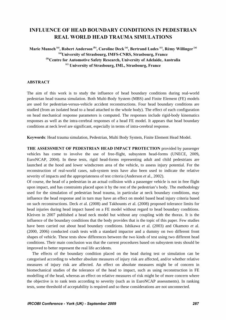
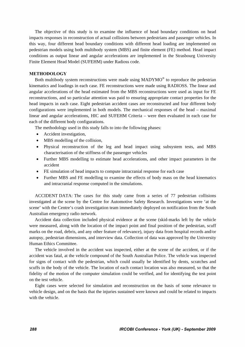
ACCIDENT RECONSTRUCTION: Multi-Body System: The MBS model that was used for the simulation part of this study was developed specifically to simulate pedestrians in car-pedestrian collisions. The model was originally developed a decade ago (Garrett, 1996; Garrett, 1998), and has been improved and has used for accident simulation purposes (Anderson et al., 2005). The model consists of 17 rigid segments linked by kinematic joints, which are largely based on the model proposed by (Ishikawa et al., 1993) although some joints have been added while others have been modified. The cases that were modelled in this study involved pedestrians of varying ages and statures. The model was validated against the behaviour of a fiftieth percentile adult male, with focus on segment trajectories measured in PMHS tests by JARI (Garrett, 1996). Therefore the model had to be scaled appropriately for the simulation of each case. The anthropometric data for each pedestrian (segment dimensions, masses and moments of inertia) were derived from GEBOD (Baughman, 1983), a program which generates anthropometric segment data using regression equations derived from a database of human body measurements. In several cases, the resulting dimensions could be checked against body dimensions of the actual pedestrians, measured by a member of the research team, either during interview, or at autopsy for fatal cases. In cases where the dimensions could be cross-referenced, the dimensions corresponded closely. Joint properties were not scaled in this process as it was supposed in this study that this would not affect significantly the results. The next step in the simulation process was to determine the posture of the pedestrian prior to impact. It was assumed that the both the walking velocity and the velocity of the limbs during locomotion could be ignored. The general orientation of the pedestrian relative the car was known in each of these cases, either from the pedestrian themselves or from drivers, witnesses and/or marks on the body of the pedestrian. In some cases the posture of the body of the pedestrian could be similarly determined. The impression of the bumper or grille, often indicated the orientation of the pedestrian, and the alignment of marks often indicate the position of limbs and torso as they were struck. However, in many cases it was not possible to determine the exact position or posture of the pedestrian. In these cases, several variations of the body postures, that we judged to be the most probable in each case, were modelled. The presence of ankle fractures thought to have occurred due to inversion/eversion type deformations of the ankle were used to determine the weight bearing leg at the time of impact. This reduced the number of simulations required in some cases. Each variant of the simulation was checked for plausibility against the physical evidence, to discount variants that did not produce kinematics consistent with the physical evidence. The remaining variants were analysed to check that the head impact velocity did not vary significantly between them. In all cases, this process produced simulations that could account for both the pedestrian kinematics in the actual crash and the contacts and location of injuries that resulted from the collision. An illustrative example of Madymo simulation is presented in Figure 1. Impact Configurations: Four different body configurations representing various boundary conditions (Figure 2) were implemented in the MBS reconstructions. Configurations were obtained by removing some joints 5 ms before head impact. This removing is used to disconnect the body region proximal from this point from distal. There are no forces transmitted when the joint is removed. The four configurations were:
- Body configuration: the whole body impact the vehicle. - Head configuration: upper neck joint is removed. The head alone impacts vehicle surface. - Neck configuration: lower neck joint is removed. Only neck is linked to the head. - Thorax configuration: three joints are removed: left shoulder, right shoulder and
thorax/abdomen joints. Neck and thorax are linked to the head.
IRCOBI Conference - York (UK) - September 2009 289
The mechanical responses of the head in each simulation were defined by the maximum linear and angular acceleration measured at the centre of gravity of the head rigid body. HIC criterion was calculated from linear acceleration temporal curve.
Figure 1. An illustrative example of MADYMO simulation reconstructing one of the pedestrian cases in this study. The top frame is just before the collision and the bottom frame is at head impact.
(a) (b) (c) (d)
Figure 2. An illustrative example of the four head boundary conditions or configurations for multi-body
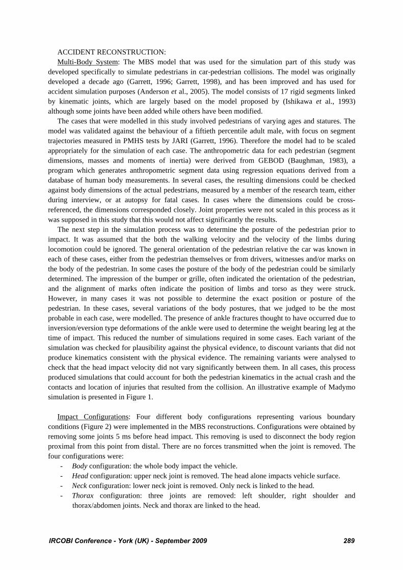
pedestrian model at 5 ms before head impact: (a) body conf., (b) thorax conf., (c) neck conf., (d) head conf. Vehicle MBS model: Vehicles that corresponded to the make, model and series of those involved in each case were obtained for the physical reconstruction process. The cars also provided the geometry of the vehicle model for the MADYMO simulation phase. A digital prismless theodolite (usually used in surveying) was used to pick out the main geometrical features of the car. These were linked with lines and these were used as a basis of the geometry created in MADYMO. The geometry was imported into Easi-CrashMAD in IGES format. The vehicle geometry was then approximated by defining planes, elliptical cylinders and ellipsoids.
Figure 3. Illustrative example of tests to determine contact-impact properties. The location is that identified in the accident investigation. The speed and angle are determined from the preliminary
MADYMO simulation.
290 IRCOBI Conference - York (UK) - September 2009
Contact-impact properties for the interaction between the pedestrian and the vehicle bumper, leading edge, hood and windscreen were determined from impact tests on the exemplar vehicle for each case. Preliminary simulations provided estimates of impact speed and energy for the leg-bumper, upper leg bumper, and head-vehicle impacts. These conditions were replicated in laboratory impact tests using EEVC WG17 subsystem impactors. The structures of each vehicle that came into contact with the pedestrian were tested with the EEVC WG17 upper leg impactor, child headform or adult headform as appropriate. An illustrative example of tests to determine contact-impact properties of vehicle is presented in Figure 3. The results of each test (leg and head impacts) were analysed to provide rate-dependent contact properties that conformed to Equation 1:
,
,
1 0
1 0
Elastic load
Elastic unload
F cF
F c
δ δ
δ δ
−
−
⎧ ⎫⎡ ⎤+ ≥⎣ ⎦⎪ ⎪= ⎨ ⎬⎡ ⎤+ ≤⎪ ⎪⎣ ⎦⎩ ⎭
(Equation 1.)
where FElastic−* are numerically defined loading curves and c is a damping parameter; all quantities were determined from the experimental test using methods described in Anderson et al. (2009). Essentially, the contact model provides realistic pulses over a range of impact energies. In some cases, more than one test was made at different impact energies to ensure the validity of the contact model. FE head model: The Strasbourg University Finite Element Head Model (SUFEHM) is a FE model developed by Kang et al. (1997) using the RADIOSS® code.
Figure 4. Strasbourg University Finite Element Head Model (SUFEHM) components.
As shown in Figure 4, this model includes the main anatomical features such as skull, falx, tentorium, subarachnoid space (dura mater, CSF and arachnoid), cerebral hemisphere, and brain stem associated with the corpus callosum. The mechanical properties of this model are detailed in Kang et al. (1997).This model of an anatomic head has been validated by Willinger et al. (1999) with regard to experimental tests (Nahum et al. 1997, Trosseille et al. 1992, Yoganandan et al. 1994). Tolerance limits have been established for this model by reconstructing 68 real world accident cases. These tolerance limits are specific to defined injury mechanisms. The first mechanical parameter is the minimum pressure in Cerebral Spinal Fluid (CSF) which is correlated to subdural or subarachnoid haematoma. The second one is the brain Von Mises stress which is correlated to diffuse axonal injury (DAI). Proposed tolerance limits (Deck et al. 2008) for a 50% risk of subdural haematoma, mild and severe DAI injuries are respectively -135 kPa, 26 kPa and 33 kPa. It should be mentioned that the injury parameters can be computed either by simulating a direct impact against an impacted structure or in the present study by driving the model with an acceleration
IRCOBI Conference - York (UK) - September 2009 291
field applied to a rigid skull. The acceleration field consists in three linear accelerations and three angular accelerations extracted from the MBS simulation and applied at the centre of gravity of the head. In such acceleration field, no consideration was made on skull strain as a rigid skull assumption has been made in the framework of the present study. Therefore, none of the cases considered sustained skull fracture. RESULTS In order to compare results obtained for the different configurations, a difference ratio R in percentage (Equation 2) is calculated for the values X (linear or angular acceleration, HIC,...) and for a given configuration i (head, neck and thorax), on the referenced body configuration.
( ) 1 .100iR Xi Xbody= −⎡ ⎤⎣ ⎦ (Equation 2.)
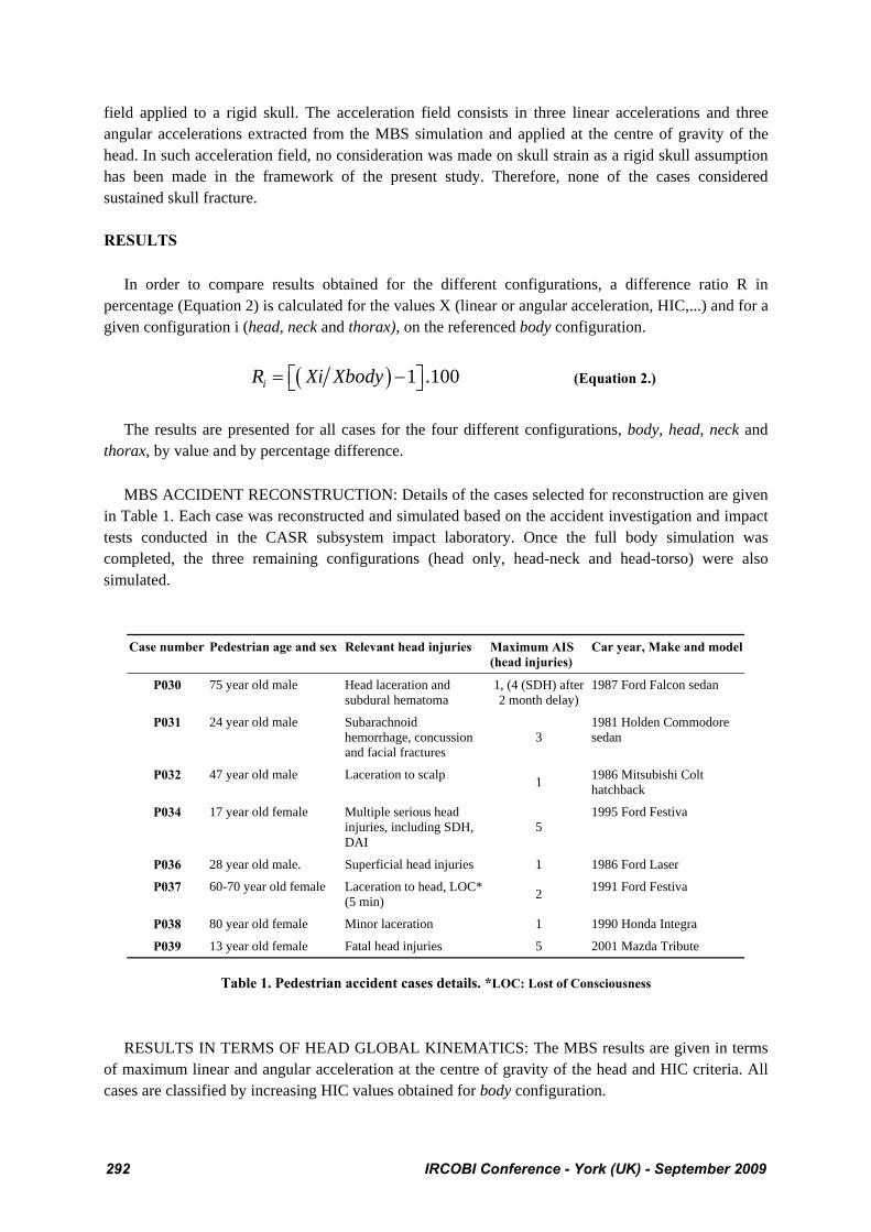
The results are presented for all cases for the four different configurations, body, head, neck and thorax, by value and by percentage difference. MBS ACCIDENT RECONSTRUCTION: Details of the cases selected for reconstruction are given in Table 1. Each case was reconstructed and simulated based on the accident investigation and impact tests conducted in the CASR subsystem impact laboratory. Once the full body simulation was completed, the three remaining configurations (head only, head-neck and head-torso) were also simulated.
Case number Pedestrian age and sex Relevant head injuries Maximum AIS (head injuries)
Car year, Make and model
P030 75 year old male Head laceration and subdural hematoma
1, (4 (SDH) after 2 month delay)
1987 Ford Falcon sedan
P031 24 year old male Subarachnoid hemorrhage, concussion and facial fractures
3 1981 Holden Commodore sedan
P032 47 year old male Laceration to scalp 1 1986 Mitsubishi Colt hatchback
P034 17 year old female Multiple serious head injuries, including SDH, DAI
5 1995 Ford Festiva
P036 28 year old male. Superficial head injuries 1 1986 Ford Laser
P037 60-70 year old female Laceration to head, LOC* (5 min) 2 1991 Ford Festiva
P038 80 year old female Minor laceration 1 1990 Honda Integra
P039 13 year old female Fatal head injuries 5 2001 Mazda Tribute
Table 1. Pedestrian accident cases details. *LOC: Lost of Consciousness RESULTS IN TERMS OF HEAD GLOBAL KINEMATICS: The MBS results are given in terms of maximum linear and angular acceleration at the centre of gravity of the head and HIC criteria. All cases are classified by increasing HIC values obtained for body configuration.
292 IRCOBI Conference - York (UK) - September 2009
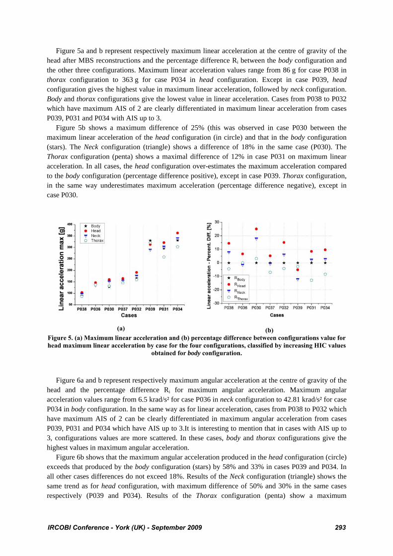
Figure 5a and b represent respectively maximum linear acceleration at the centre of gravity of the head after MBS reconstructions and the percentage difference Ri between the body configuration and the other three configurations. Maximum linear acceleration values range from 86 g for case P038 in thorax configuration to 363 g for case P034 in head configuration. Except in case P039, head configuration gives the highest value in maximum linear acceleration, followed by neck configuration. Body and thorax configurations give the lowest value in linear acceleration. Cases from P038 to P032 which have maximum AIS of 2 are clearly differentiated in maximum linear acceleration from cases P039, P031 and P034 with AIS up to 3. Figure 5b shows a maximum difference of 25% (this was observed in case P030 between the maximum linear acceleration of the head configuration (in circle) and that in the body configuration (stars). The Neck configuration (triangle) shows a difference of 18% in the same case (P030). The Thorax configuration (penta) shows a maximal difference of 12% in case P031 on maximum linear acceleration. In all cases, the head configuration over-estimates the maximum acceleration compared to the body configuration (percentage difference positive), except in case P039. Thorax configuration, in the same way underestimates maximum acceleration (percentage difference negative), except in case P030.
(a)
(b) Figure 5. (a) Maximum linear acceleration and (b) percentage difference between configurations value for head maximum linear acceleration by case for the four configurations, classified by increasing HIC values
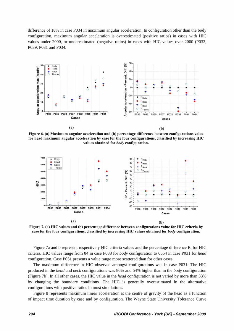
obtained for body configuration. Figure 6a and b represent respectively maximum angular acceleration at the centre of gravity of the head and the percentage difference Ri for maximum angular acceleration. Maximum angular acceleration values range from 6.5 krad/s² for case P036 in neck configuration to 42.81 krad/s² for case P034 in body configuration. In the same way as for linear acceleration, cases from P038 to P032 which have maximum AIS of 2 can be clearly differentiated in maximum angular acceleration from cases P039, P031 and P034 which have AIS up to 3.It is interesting to mention that in cases with AIS up to 3, configurations values are more scattered. In these cases, body and thorax configurations give the highest values in maximum angular acceleration. Figure 6b shows that the maximum angular acceleration produced in the head configuration (circle) exceeds that produced by the body configuration (stars) by 58% and 33% in cases P039 and P034. In all other cases differences do not exceed 18%. Results of the Neck configuration (triangle) shows the same trend as for head configuration, with maximum difference of 50% and 30% in the same cases respectively (P039 and P034). Results of the Thorax configuration (penta) show a maximum
IRCOBI Conference - York (UK) - September 2009 293
difference of 18% in case P034 in maximum angular acceleration. In configuration other than the body configuration, maximum angular acceleration is overestimated (positive ratios) in cases with HIC values under 2000, or underestimated (negative ratios) in cases with HIC values over 2000 (P032, P039, P031 and P034.
(a)
(b)
Figure 6. (a) Maximum angular acceleration and (b) percentage difference between configurations value for head maximum angular acceleration by case for the four configurations, classified by increasing HIC
values obtained for body configuration.
(a)
(b) Figure 7. (a) HIC values and (b) percentage difference between configurations value for HIC criteria by
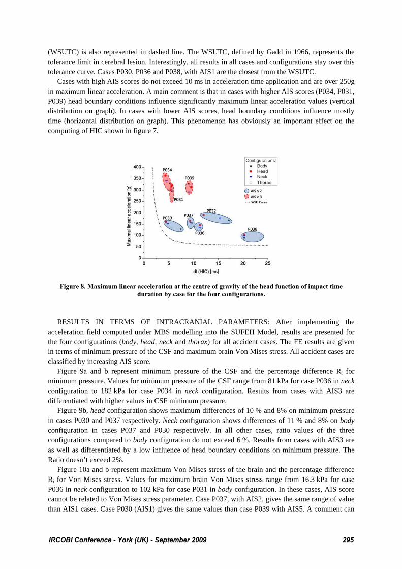
case for the four configurations, classified by increasing HIC values obtained for body configuration. Figure 7a and b represent respectively HIC criteria values and the percentage difference Ri for HIC criteria. HIC values range from 84 in case P038 for body configuration to 6554 in case P031 for head configuration. Case P031 presents a value range more scattered than for other cases. The maximum difference in HIC observed amongst configurations was in case P031: The HIC produced in the head and neck configurations was 86% and 54% higher than in the body configuration (Figure 7b). In all other cases, the HIC value in the head configuration is not varied by more than 33% by changing the boundary conditions. The HIC is generally overestimated in the alternative configurations with positive ratios in most simulations. Figure 8 represents maximum linear acceleration at the centre of gravity of the head as a function of impact time duration by case and by configuration. The Wayne State University Tolerance Curve
294 IRCOBI Conference - York (UK) - September 2009
(WSUTC) is also represented in dashed line. The WSUTC, defined by Gadd in 1966, represents the tolerance limit in cerebral lesion. Interestingly, all results in all cases and configurations stay over this tolerance curve. Cases P030, P036 and P038, with AIS1 are the closest from the WSUTC. Cases with high AIS scores do not exceed 10 ms in acceleration time application and are over 250g in maximum linear acceleration. A main comment is that in cases with higher AIS scores (P034, P031, P039) head boundary conditions influence significantly maximum linear acceleration values (vertical distribution on graph). In cases with lower AIS scores, head boundary conditions influence mostly time (horizontal distribution on graph). This phenomenon has obviously an important effect on the computing of HIC shown in figure 7.
Figure 8. Maximum linear acceleration at the centre of gravity of the head function of impact time duration by case for the four configurations.
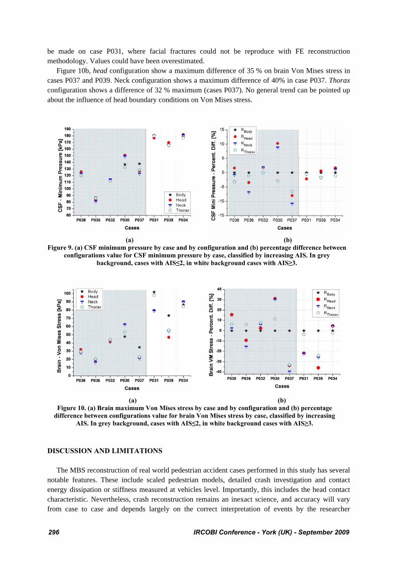
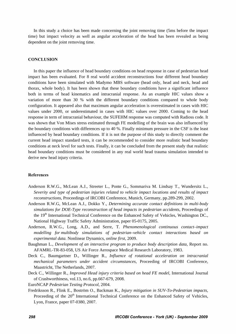
RESULTS IN TERMS OF INTRACRANIAL PARAMETERS: After implementing the acceleration field computed under MBS modelling into the SUFEH Model, results are presented for the four configurations (body, head, neck and thorax) for all accident cases. The FE results are given in terms of minimum pressure of the CSF and maximum brain Von Mises stress. All accident cases are classified by increasing AIS score. Figure 9a and b represent minimum pressure of the CSF and the percentage difference Ri for minimum pressure. Values for minimum pressure of the CSF range from 81 kPa for case P036 in neck configuration to 182 kPa for case P034 in neck configuration. Results from cases with AIS3 are differentiated with higher values in CSF minimum pressure. Figure 9b, head configuration shows maximum differences of 10 % and 8% on minimum pressure in cases P030 and P037 respectively. Neck configuration shows differences of 11 % and 8% on body configuration in cases P037 and P030 respectively. In all other cases, ratio values of the three configurations compared to body configuration do not exceed 6 %. Results from cases with AIS3 are as well as differentiated by a low influence of head boundary conditions on minimum pressure. The Ratio doesn’t exceed 2%. Figure 10a and b represent maximum Von Mises stress of the brain and the percentage difference Ri for Von Mises stress. Values for maximum brain Von Mises stress range from 16.3 kPa for case P036 in neck configuration to 102 kPa for case P031 in body configuration. In these cases, AIS score cannot be related to Von Mises stress parameter. Case P037, with AIS2, gives the same range of value than AIS1 cases. Case P030 (AIS1) gives the same values than case P039 with AIS5. A comment can
IRCOBI Conference - York (UK) - September 2009 295
be made on case P031, where facial fractures could not be reproduce with FE reconstruction methodology. Values could have been overestimated. Figure 10b, head configuration show a maximum difference of 35 % on brain Von Mises stress in cases P037 and P039. Neck configuration shows a maximum difference of 40% in case P037. Thorax configuration shows a difference of 32 % maximum (cases P037). No general trend can be pointed up about the influence of head boundary conditions on Von Mises stress.
(a) (b) Figure 9. (a) CSF minimum pressure by case and by configuration and (b) percentage difference between
configurations value for CSF minimum pressure by case, classified by increasing AIS. In grey background, cases with AIS≤2, in white background cases with AIS≥3.
(a) (b)
Figure 10. (a) Brain maximum Von Mises stress by case and by configuration and (b) percentage difference between configurations value for brain Von Mises stress by case, classified by increasing
AIS. In grey background, cases with AIS≤2, in white background cases with AIS≥3. DISCUSSION AND LIMITATIONS The MBS reconstruction of real world pedestrian accident cases performed in this study has several notable features. These include scaled pedestrian models, detailed crash investigation and contact energy dissipation or stiffness measured at vehicles level. Importantly, this includes the head contact characteristic. Nevertheless, crash reconstruction remains an inexact science, and accuracy will vary from case to case and depends largely on the correct interpretation of events by the researcher
296 IRCOBI Conference - York (UK) - September 2009
performing the reconstruction. While every care was taken in these reconstructions, there will always remain some uncertainty over the fidelity of any given reconstruction in terms of assumptions and unknowns. In some cases, the locomotion of the pedestrian may have influenced the kinematics of the pedestrian in the collision, and these effects are not included in the simulations in this study. Cases here reconstructed are illustrative rather than exhaustive and merely provide data for this study. The exactness of the reconstructions is therefore not the most important point as the objective was to analyse head boundary conditions in some representative accident conditions. Therefore, the influence of head boundary conditions on head impacts responses has been investigated under real-world pedestrian accident reconstruction. This work shows that head boundary conditions influence significally the head responses in terms of acceleration field, HIC and head FEM response and therefore on head injury prediction assessment. The multibody results seem to show clearly that the relationship between linear and angular acceleration is influenced by the neck boundary conditions. Linear acceleration values varied up to 25 % as a function of head boundary loading. HIC criteria and angular accelerations values varied up to 35 % from the whole body configuration (except in one case where the variation was greater). Linear acceleration values are generally underestimated when head is treated as a free body. Von Mises stress estimated through FE modelling of the brain was also influenced by the boundary conditions with differences up to 40 %. Finally minimum pressure in the CSF is the least influenced. In order to study the influence on head impact duration and maximum linear acceleration relative to AIS scores, a more systematic parametric approach is needed. This parametric approach could also show an influence on FE model intracerebral parameters relative to AIS scores or head injuries, which was not the aim of this current study. Several cases have particular impact characteristics that should be noted in relation to these results. Case P031 presented severe facial fractures that can’t be reproduced with the rigid skull assumption used in this study. The impact parameters estimated for this case are likely to be overestimates, especially HIC and Von Mises stress values. Case P039 presents quit different trends compared to other results, in particular for the acceleration field. In this case, the head impacted the bonnet structure. In all other cases, the head impact the windscreen or the pillars. Finally case P032, in which the pedestrian presented just scalp lacerations, has a HIC value around 2700 for the four configurations. It is suspected that the impact speed estimated in this case is too high, and especially because the subsystem impact tests conducted in connection with this case at 9.4 m/s and 14.0 m/s produced HIC values of 221 and 1307. The impact speed of the vehicle was ascertained after discussions with the driver, in combination with a lack of braking marks on the road. It is possible that the driver overestimated his speed. Errors between estimated and actual speeds in the cases need to be considered particularly when examining the link between injury severity and head injury parameters. It is often difficult a priori to determine if particular cases contain large errors of this type. However such errors affect the examination of the sensitivity of the reconstruction to choices of boundary conditions less, because the vehicle impact speed is constant across all simulations, and if the objective is to evaluate the sensitivity of the simulation to boundary conditions, the case becomes essentially illustrative. An assumption has been made in this study concerning the rigid skull. A study published by Deck et al (2007) shows that this assumption influences the model response for short-duration impacts. Indeed, short impacts correspond to a very rigid impacted surface. In such case, the skull deformation has an influence on the intracranial mechanical behavior. Concerning impacts against softer surfaces, the skull trend to deform is decreased and as a matter of fact, its influence is reduced. In a further step skull structure interaction force must be investigated in parallel with the neck loading in addition to the head kinematics. This would help to have a full understanding of the head boundary condition influence on head injury risk assessment.
IRCOBI Conference - York (UK) - September 2009 297
In this study a choice has been made concerning the joint removing time (5ms before the impact time) but impact velocity as well as angular acceleration of the head has been revealed as being dependent on the joint removing time. CONCLUSION In this paper the influence of head boundary conditions on head response in case of pedestrian head impact has been evaluated. For 8 real world accident reconstructions four different head boundary conditions have been simulated with Madymo MBS software (head only, head and neck, head and thorax, whole body). It has been shown that these boundary conditions have a significant influence both in terms of head kinematics and intracranial response. As an example HIC values show a variation of more than 30 % with the different boundary conditions compared to whole body configuration. It appeared also that maximum angular acceleration is overestimated in cases with HIC values under 2000, or underestimated in cases with HIC values over 2000. Coming to the head response in term of intracranial behaviour, the SUFEHM response was computed with Radioss code. It was shown that Von Mises stress estimated through FE modelling of the brain was also influenced by the boundary conditions with differences up to 40 %. Finally minimum pressure in the CSF is the least influenced by head boundary conditions. If it is not the purpose of this study to directly comment the current head impact standard tests, it can be recommended to consider more realistic head boundary conditions at neck level for such tests. Finally, it can be concluded from the present study that realistic head boundary conditions must be considered in any real world head trauma simulation intended to derive new head injury criteria. References Anderson R.W.G., McLean A.J., Streeter L., Ponte G., Sommariva M. Lindsay T., Wundersitz L.,
Severity and type of pedestrian injuries related to vehicle impact locations and results of impact reconstructions, Proceedings of IRCOBI Conference, Munich, Germany, pp.289-299, 2002.
Anderson R.W.G, McLean A.J., Dokko Y., Determining accurate contact definitions in multi-body simulations for DOE-Type reconstruction of head impacts in pedestrian accidents, Proceedings of the 19th International Technical Conference on the Enhanced Safety of Vehicles, Washington DC., National Highway Traffic Safety Administration, paper 05-0175, 2005.
Anderson, R.W.G., Long, A.D., and Serre, T. Phenomenological continuous contact–impact modelling for multibody simulations of pedestrian–vehicle contact interactions based on experimental data. Nonlinear Dynamics, online first, 2009.
Baughman L., Development of an interactive program to produce body description data, Report no. AFAMRL-TR-83-058, US Air Force Aerospace Medical Research Laboratory, 1983.
Deck C., Baumgartner D., Willinger R., Influence of rotational acceleration on intracranial mechanical parameters under accident circumstances, Proceeding of IRCOBI Conference, Maastricht, The Netherlands, 2007.
Deck C., Willinger R., Improved Head injury criteria based on head FE model, International Journal of Crashworthiness, vol.13, no.6, pp.667-679, 2008.
EuroNCAP Pedestrian Testing Protocol, 2004. Fredriksson R., Flink E., Boström O., Backman K., Injury mitigation in SUV-To-Pedestrian impacts,
Proceeding of the 20th International Technical Conference on the Enhanced Safety of Vehicles, Lyon, France, paper 07-0380, 2007.
298 IRCOBI Conference - York (UK) - September 2009
Gadd C.W., Use of a weighted – impulse criterion for estimating injury hazard, Proceeding of the 10th STAPP Car Crash Conference, pp. 164-174, 1966.
Garrett M., Head impact modelling using computer accident simulation based on cadaver records, 24th International workshop on human subjects for biomechanical research, Albuquerque, New Mexico, US Department of Transportation, National Highways Traffic Safety Administration, 1996.
Garrett M., Head impact modelling using MADYMO simulations of documented pedestrian accidents, Conference on Pedestrian Safety, Melbourne, Victoria, VicRoads, RACV, Federal Office of Road Safety, Australian Hotels Association, 1998.
Ishikawa H., Kajzer J., Schroeder G., Computer simulation of impact response of the human body in car-pedestrian accidents, Proceeding of the 37th Stapp Car Crash Conference, San Antonio, Society of Automotive Engineer, 1993.
Ishikawa T., Kore H., Furumoto A., Kuroda S., Evaluation of pedestrian protection structure using impactors and full-scale dummy tests, Proceedings of the 18th International Technical Conference on the Enhanced Safety of Vehicles, Nagoya, Japan, paper 271, 2003.
Kang H.S., Willinger R., Diaw B., Chinn B., Validation of a 3D anatomic human head model and replication of head impact in motorcycle accident by finite element modelling, Proceeding of the 41st Stapp Car Crash Conference, SAE paper 973339, pp.329-338, 1997.
Kleiven S., Predictors for traumatic brain injuries evaluated through accident reconstructions, Stapp Car Crash Journal, Vol. 51, pp. 81-114, 2007.
Nahum A.., Smith R., Ward C.C., Intracranial pressure dynamics during head impact, Proceedings of the 21th Stapp Car Crash Conference, pp.339-366, 1997.
OkamotoY., Sugimoto T., Enomoto K., Kikuchi Y., Pedestrian head impact conditions depending on the vehicle front shape and its construction – full model simulation, Proceeding of the IRCOBI Conference, Montpellier, France, 2000.
Okamoto Y., Kikuchi Y., A study of pedestrian head injury evaluation method, Proceeding of the IRCOBI Conference, Madrid, Spain, 2006.
Takhounts E.G., Ridella S.A., Hasija V., Tannous R.E., Campbell J.Q., Malone D., Danelson K., Stitzel J., Rowson S., Duma S., Investigation of traumatic brain injuries using the next generation of simulated injury monitor (SIMon) finite element model, Stapp Car Crash Journal, Vol. 52, pp. 1-31, 2008.
Tinard V., Deck C., Meyer F., Bourdet N., Willinger R., Influence of pedestrian head surrogate and boundary conditions on head injury risk prediction, International Journal of Crashworthiness, In Press, 2009.
Trosseille X., Tarrière C., Development of a FEM of the human head according to specific test protocol, Proceedings of the 36th Stapp Car Crash Conference, pp.235-253, 1992.
UNECE, Regulation no. 78/2009 of the European Parliament and of the Council of 14 January 2009 on the type-approval of motor vehicles with regard to the protection of pedestrians and other vulnerable road users, 2009.
Willinger R., Kang H.S., Diaw B.M., 3D human head finite element model validation against two experimental impacts, Annals of Biomed. Eng., vol. 27(3), pp.403-410, 1999.
Yoganandan N., Pintar A., Biomechanics of skull fracture, Proceedings of the Head Injury Symposium, pp.227-236, 1994.
IRCOBI Conference - York (UK) - September 2009 299
300 IRCOBI Conference - York (UK) - September 2009