Inkjet printing of resistively loaded FSS for microwave absorbers Zabri, S. N., Cahill, R., Conway, G., & Schuchinsky, A. (2015). Inkjet printing of resistively loaded FSS for microwave absorbers. Electronics Letters, 51(13), 999-1001. DOI: 10.1049/el.2015.0696 Published in: Electronics Letters Document Version: Peer reviewed version Queen's University Belfast - Research Portal: Link to publication record in Queen's University Belfast Research Portal Publisher rights Copyright 2015 The Institution of Engineering and Technology This paper is a postprint of a paper submitted to and accepted for publication in Electronic Letters and is subject to Institution of Engineering and Technology Copyright. The copy of record is available at IET Digital Library General rights Copyright for the publications made accessible via the Queen's University Belfast Research Portal is retained by the author(s) and / or other copyright owners and it is a condition of accessing these publications that users recognise and abide by the legal requirements associated with these rights. Take down policy The Research Portal is Queen's institutional repository that provides access to Queen's research output. Every effort has been made to ensure that content in the Research Portal does not infringe any person's rights, or applicable UK laws. If you discover content in the Research Portal that you believe breaches copyright or violates any law, please contact [email protected]. Download date:12. Jul. 2018
Transcript
Inkjet printing of resistively loaded FSS for microwave absorbers
Zabri, S. N., Cahill, R., Conway, G., & Schuchinsky, A. (2015). Inkjet printing of resistively loaded FSS formicrowave absorbers. Electronics Letters, 51(13), 999-1001. DOI: 10.1049/el.2015.0696
Published in:Electronics Letters
Document Version:Peer reviewed version
Queen's University Belfast - Research Portal:Link to publication record in Queen's University Belfast Research Portal
Publisher rightsCopyright 2015 The Institution of Engineering and Technology
This paper is a postprint of a paper submitted to and accepted for publication in Electronic Letters and is subject to Institution of Engineeringand Technology Copyright. The copy of record is available at IET Digital Library
General rightsCopyright for the publications made accessible via the Queen's University Belfast Research Portal is retained by the author(s) and / or othercopyright owners and it is a condition of accessing these publications that users recognise and abide by the legal requirements associatedwith these rights.
Take down policyThe Research Portal is Queen's institutional repository that provides access to Queen's research output. Every effort has been made toensure that content in the Research Portal does not infringe any person's rights, or applicable UK laws. If you discover content in theResearch Portal that you believe breaches copyright or violates any law, please contact [email protected].
InkJet Printing of Resistively Loaded FSS for Microwave
Absorbers
Journal: Electronics Letters
Manuscript ID: ELL-2015-0696
Manuscript Type: Letter
Date Submitted by the Author: 27-Feb-2015
Complete List of Authors: Zabri, Siti; Queen's University Belfast, Northern Ireland Science Park Cahill, Robert; Queen's University Belfast, Institute of Electronics, Communications and Information Technology Conway, Gareth; Queens University Belfast, ECIT Schuchinsky, Alexander; Queens University Belfast, ECIT;
Keywords: FREQUENCY-SELECTIVE SURFACES
1
InkJet Printing of Resistively Loaded FSS for Microwave Absorbers S. N. Zabri, R. Cahill, G. Conway, and A. Schuchinsky
Inkjet printing is proposed as a means to create the resistively loaded elements of
a Frequency Selective Surface (FSS) which suppresses radar backscatter when
placed above a metal ground plane. Spectral transmission and reflection measurements from 9 to 18 GHz show that the dot density of the printed features
and the volume ratio of an aqueous vehicle and nano silver ink mixture can be
selected to obtain surface resistances in the range 1.2 - 200 Ω/sq.
Introduction: Thin microwave absorbers composed of metal backed
resistively loaded FSS [1]–[3] provide an attractive solution for radar
cloaking where the main design drivers are weight and thickness. The
equivalent network of the structure consists of a parallel connected FSS
sheet impedance, which can be described by an LCR circuit, and the
inductance which is presented by the ground plane spaced a distance
< λ/4 apart [1]. At resonance the two reactive components of the
complex impedance cancel and the absorber can be impedance matched
to free space (377 Ω) by carefully selecting the resistance which is used
to represent the FSS loss. Therefore unlike conventional bandstop FSS
where it is desirable to employ high conductivity metal to create the
resonant elements that form the periodic array [4], [5], absorbers based
on this technology require selective patterning of material which
exhibits a small surface resistance. For example the authors have
recently reported the design of thin FSS based microwave absorbers
composed of rectangular [6] and nested hexagonal loop [7] elements
with surface resistances in the range 13 -175 Ω/sq. Experimental
prototypes of both arrangements were constructed using commercially
available graphite and carbon based shielding paint, and the required
resistive loading was realised by adjusting the thickness of the ink
features [6]. However the minor variations of micron thick paint layers
deposited on the stencil printed substrates resulted in measured values
that were 20% [6] and 30% [7] higher than the nominal design for
optimum computed backscatter response. In this letter we describe an
alternative manufacturing strategy which provides a low cost, simple
and repeatable means to solve this problem. By employing an ink-jet
printer to simultaneously pattern the FSS elements on the substrate and
digitally control the dot density of a novel solution composed of an
aqueous vehicle and nano silver ink mixture, we show that it is possible
to obtain surface resistances that are much closer to the specified values
for optimum absorber performance.
Characterisation procedure: Very accurate electrical characterisation of
materials at microwave [6] and millimetre wavelengths [8] can be
obtained by curve fitting computed transmission coefficients to the
experimental spectral response of single and multiple layer FSS. In this
study CST Microwave Studio software [9] was employed to obtain the
physical dimensions of a periodic array of copper dipoles which was
designed to resonate at 15.3 GHz when exposed to TE (vertically)
polarised waves at normal incidence. Figure 1 shows the array
arrangement and physical dimensions of the dipoles which were printed
on a 0.14 mm thick coated PET substrate with permittivity 2.5
(NoveleTM
[10]). The surface resistance used in the numerical model
was adjusted to achieve the best fit with either measured transmission or
reflection response plots of inkjet printed FSS with the same
dimensions, but constructed with dipoles that were formed by using
different volume ratios of a solution composed of MetalonTM
JS-B25P
[10] nano silver ink and MetalonTM
aqueous vehicle. This electrically
conductive ink is a water based material with a 25 wt% Ag content that
is formulated to give thin film sheet resistances as low as 60
milliohm/sq. To obtain surface resistance values up to a few hundred
Ω/sq for single pass traces, 1:5, 1:7 and 1:9 (inkmL: aqueous vehiclemL)
mixture compositions were prepared and used in an Epson Stylus C88+
inkjet printer which was set to operate with a single ink cartridge and
digitally configured for black and white printing and best photo quality
resolution. The piezoelectric head delivers ink droplets on request and
achieves resolutions of 360 dots per inch in both the vertical and
horizontal planes. The 180 nozzles in the monochrome head produce
3 pL ink droplets on the substrate with a maximum thickness of 0.27
mm. The artwork for the periodic arrays was generated with DipTrace
software [11] and the RGB colour codes were varied between (0, 0, 0)
and (30, 30, 30) to produce a range of 9 different dot densities. In the
manufacturing process this setting and the silver ink mixture
concentration can be adjusted to obtain precisely the surface resistance
value that is required for optimum design of the FSS absorber elements.
After inkjet printing, the 15×15 cm2
dipole arrays were cured at room
temperature for 24 hours to ensure complete evaporation of the solution
based host material and stabilisation of the connectivity between the
silver nano particles. Experimental data was acquired at normal
incidence with the FSS placed 47 cm from the apertures of a pair of
standard gain horns which cover the frequency range 9 – 18 GHz. For
accurate electrical characterisation of materials, numerical data should
be fitted to curves that exhibit well defined nulls at resonance [8]. This
was achieved by using two different time gated experimental
arrangements in an anechoic chamber:
(i) transmission responses of the FSS for surface resistances in the
range 1.2 - 20 Ω/sq (an example is shown in Figure 2)
(ii) reflection responses of the FSS placed 4-5 mm above a metal plate
were required for surface resistances in the range 20 - 200 Ω/sq
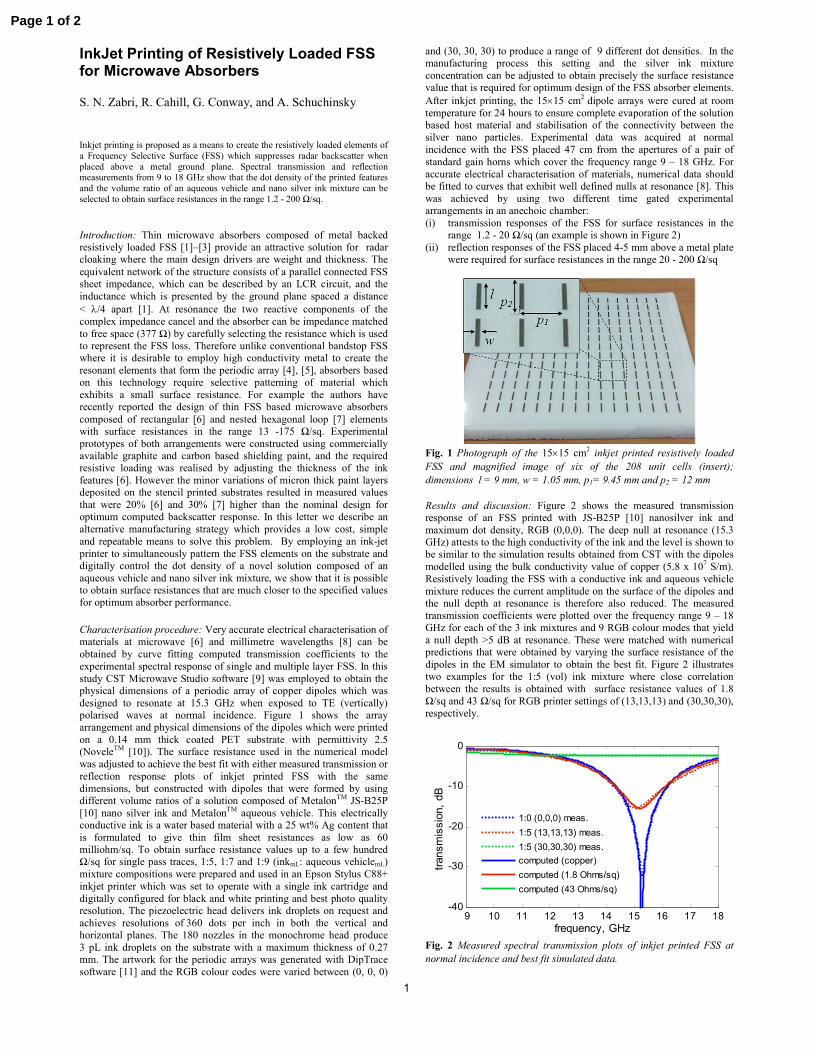
Fig. 1 Photograph of the 15×15 cm
2 inkjet printed resistively loaded
FSS and magnified image of six of the 208 unit cells (insert);
dimensions l = 9 mm, w = 1.05 mm, p1= 9.45 mm and p2 = 12 mm
Results and discussion: Figure 2 shows the measured transmission
response of an FSS printed with JS-B25P [10] nanosilver ink and
maximum dot density, RGB (0,0,0). The deep null at resonance (15.3
GHz) attests to the high conductivity of the ink and the level is shown to
be similar to the simulation results obtained from CST with the dipoles
modelled using the bulk conductivity value of copper (5.8 x 10⁷ S/m).
Resistively loading the FSS with a conductive ink and aqueous vehicle
mixture reduces the current amplitude on the surface of the dipoles and
the null depth at resonance is therefore also reduced. The measured
transmission coefficients were plotted over the frequency range 9 – 18
GHz for each of the 3 ink mixtures and 9 RGB colour modes that yield
a null depth >5 dB at resonance. These were matched with numerical
predictions that were obtained by varying the surface resistance of the
dipoles in the EM simulator to obtain the best fit. Figure 2 illustrates
two examples for the 1:5 (vol) ink mixture where close correlation
between the results is obtained with surface resistance values of 1.8
Ω/sq and 43 Ω/sq for RGB printer settings of (13,13,13) and (30,30,30),
respectively.
Fig. 2 Measured spectral transmission plots of inkjet printed FSS at
normal incidence and best fit simulated data.
9 10 11 12 13 14 15 16 17 18-40
-30
-20
-10
0
frequency, GHz
transmission, dB
1:0 (0,0,0) meas.
1:5 (13,13,13) meas.
1:5 (30,30,30) meas.
computed (copper)
computed (1.8 Ohms/sq)
computed (43 Ohms/sq)
Page 1 of 2
2
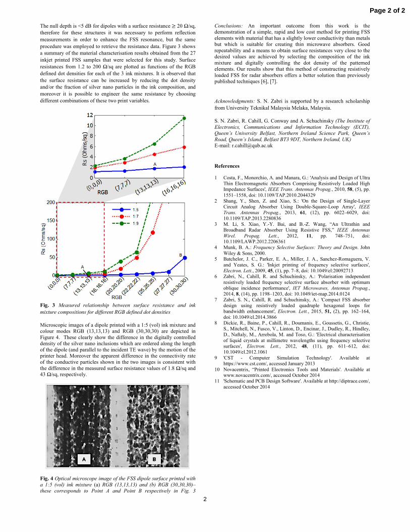
The null depth is <5 dB for dipoles with a surface resistance 20 Ω/sq,
therefore for these structures it was necessary to perform reflection
measurements in order to enhance the FSS resonance, but the same
procedure was employed to retrieve the resistance data. Figure 3 shows
a summary of the material characterisation results obtained from the 27
inkjet printed FSS samples that were selected for this study. Surface
resistances from 1.2 to 200 Ω/sq are plotted as functions of the RGB
defined dot densities for each of the 3 ink mixtures. It is observed that
the surface resistance can be increased by reducing the dot density
and/or the fraction of silver nano particles in the ink composition, and
moreover it is possible to engineer the same resistance by choosing
different combinations of these two print variables.
Fig. 3 Measured relationship between surface resistance and ink
mixture compositions for different RGB defined dot densities
Microscopic images of a dipole printed with a 1:5 (vol) ink mixture and
colour modes RGB (13,13,13) and RGB (30,30,30) are depicted in
Figure 4. These clearly show the difference in the digitally controlled
density of the silver nano inclusions which are ordered along the length
of the dipole (and parallel to the incident TE wave) by the motion of the
printer head. Moreover the apparent difference in the connectivity rate
of the conductive particles shown in the two images is consistent with
the difference in the measured surface resistance values of 1.8 Ω/sq and
43 Ω/sq, respectively.
Fig. 4 Optical microscope image of the FSS dipole surface printed with
a 1:5 (vol) ink mixture (a) RGB (13,13,13) and (b) RGB (30,30,30)–
these corresponds to Point A and Point B respectively in Fig. 3
Conclusions: An important outcome from this work is the
demonstration of a simple, rapid and low cost method for printing FSS
elements with material that has a slightly lower conductivity than metals
but which is suitable for creating thin microwave absorbers. Good
repeatability and a means to obtain surface resistances very close to the
desired values are achieved by selecting the composition of the ink
mixture and digitally controlling the dot density of the patterned
elements. Our results show that this method of constructing resistively
loaded FSS for radar absorbers offers a better solution than previously
published techniques [6], [7].
Acknowledgments: S. N. Zabri is supported by a research scholarship
from University Teknikal Malaysia Melaka, Malaysia.
S. N. Zabri, R. Cahill, G. Conway and A. Schuchinsky (The Institute of
Electronics, Communications and Information Technology (ECIT),
Queen’s University Belfast, Northern Ireland Science Park, Queen’s
Road, Queen’s Island, Belfast BT3 9DT, Northern Ireland, UK)