INSTALLATION, MAINTENANCE, SERVICE INSTRUCTIONS & ILLUSTRATED PARTS LIST THIS MANUAL INCLUDES INFORMATION PROPRIETARY TO AIRGLAS, INC. AND SHALL NOT BE USED TO MANUFACTURE OR REPRODUCE WITHOUT PERMISSION OF AIRGLAS, INC. AIRGLAS MANUAL NO. LH4000-105 MODEL LH4000 Ski Kit For Cessna 180 & 185 Airplanes CODE INDENT. NO. 17564 AIRGLAS INC.®
Transcript
INSTALLATION, MAINTENANCE, SERVICE
INSTRUCTIONS & ILLUSTRATED PARTS LIST
THIS MANUAL INCLUDES INFORMATION PROPRIETARY TO AIRGLAS, INC. AND SHALL NOT BE USED TO MANUFACTURE OR REPRODUCE WITHOUT PERMISSION OF AIRGLAS, INC.
AIRGLAS MANUAL NO. LH4000-105
MODEL LH4000 Ski KitFor
Cessna 180 & 185 Airplanes
CODE INDENT. NO. 17564
AIRGLAS INC.®
AIRGLAS, INC. ANCHORAGE, ALASKA
Revision No. Pages Affected Description DateInitial Release ALL ORIGINAL JANUARY 25 2005 A 1,3,8,14,16,28,29,37 REVISION JULY 11 2005
The aircraft will require brackets and attach fittings to be installed on the fuselage in order for the rigging to attach. This section of the manual describes and depicts these procedures.
DRILL OUT EXISTING (3) RIVETS, REPLACE WITH AN3-5A BOLTS. DRILL UP TO SIZE #12 BIT. MOUNT BRACKET SO THE BACK EDGE IS PARALLEL WITH THE FIREWALL STATION 0.00
DRILL OUT EXISTING (5) RIVETS, REPLACE WITH AN3-5A BOLTS, USE #12 DRILL TO UP-SIZE FOR BOLTS. ALIGN AS NEEDED FOR BEST EDGE DISTANCE.
INSTALL DOUBLER PLATE AT THE (4) FWD. BOLTS. TRIM AS NECESSARY TO FIT.
AIRGLAS, INC. ANCHORAGE, ALASKA
8
1.0 FUSELAGE PREPARATION – REAR ATTACH FITTING
AIRGLAS, INC. ANCHORAGE, ALASKA
9
1.0 FUSELAGE PREPARATION – REAR ATTACH FITTING
DRILL OUT EXISTING (5) RIVETS, REPLACE WITH AN3-5A BOLTS, USE #12 DRILL TO UP SIZE FOR BOLTS. ALIGN AS NEEDED FOR BEST EDGE DISTANCE.
Requires Blind RivetCR 3213-6-4
REAR ATTACH FITTING: Hole Pattern For Older C-180’s & 185’s
AN3-5A BOLTAN960-101 WASHERMS20365-1032 NUT(as shown on page 7)
AIRGLAS, INC. ANCHORAGE, ALASKA 10
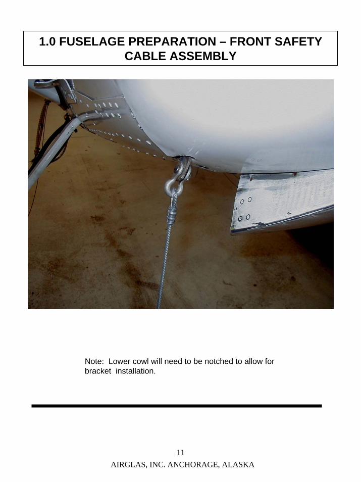
1.0 FUSELAGE PREPARATION – FRONT SAFETY CABLE ASSEMBLY
FRONT SAFETY CABLE ASSY.
AIRGLAS P/N 26-65
Cessna 180 Cessna 185
Note: Lower cowl will need to be notched to allow for bracket installation.
AIRGLAS, INC. ANCHORAGE, ALASKA 11
1.0 FUSELAGE PREPARATION – FRONT SAFETY CABLE ASSEMBLY
Note: Lower cowl will need to be notched to allow for bracket installation.
2.0 STUB AXLE INSTALLATION - OUTBOARD
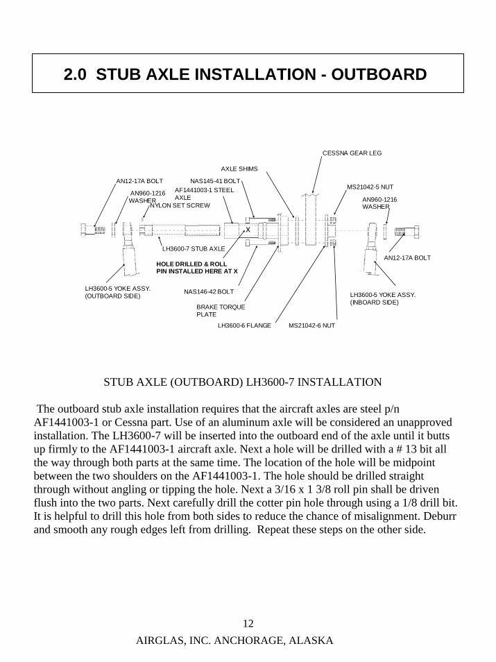
STUB AXLE (OUTBOARD) LH3600-7 INSTALLATION
The outboard stub axle installation requires that the aircraft axles are steel p/n AF1441003-1 or Cessna part. Use of an aluminum axle will be considered an unapproved installation. The LH3600-7 will be inserted into the outboard end of the axle until it butts up firmly to the AF1441003-1 aircraft axle. Next a hole will be drilled with a # 13 bit all the way through both parts at the same time. The location of the hole will be midpoint between the two shoulders on the AF1441003-1. The hole should be drilled straight through without angling or tipping the hole. Next a 3/16 x 1 3/8 roll pin shall be driven flush into the two parts. Next carefully drill the cotter pin hole through using a 1/8 drill bit. It is helpful to drill this hole from both sides to reduce the chance of misalignment. Deburr and smooth any rough edges left from drilling. Repeat these steps on the other side.
AIRGLAS, INC. ANCHORAGE, ALASKA 12
LH3600-5 YOKE ASSY. (OUTBOARD SIDE)
AN12-17A BOLT
AN960-1216 WASHER
NYLON SET SCREW
LH3600-7 STUB AXLE
AF1441003-1 STEEL AXLE
BRAKE TORQUE PLATE
AXLE SHIMS
LH3600-6 FLANGE
CESSNA GEAR LEG
NAS145-41 BOLT
NAS146-42 BOLT
AN960-1216 WASHER
LH3600-5 YOKE ASSY. (INBOARD SIDE)
AN12-17A BOLT
x
HOLE DRILLED & ROLL PIN INSTALLED HERE AT X
MS21042-6 NUT
MS21042-5 NUT
AIRGLAS, INC. ANCHORAGE, ALASKA13
3.0 STUB AXLE INSTALLATION - INBOARD
11
2
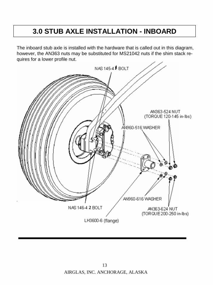
The inboard stub axle is installed with the hardware that is called out in this diagram, however, the AN363 nuts may be substituted for MS21042 nuts if the shim stack re-quires for a lower profile nut.
4.0 HYDRAULIC INSTALLATION
HYDRAULIC LINE & PUMP LOCATIONS IN FUSELAGE
The electro/hydraulic pump will be mounted aft of station 109 (the baggage bulkhead) by means of two (2) 3/8 dia. bolts that mount through the belly skin approximately 5.5” right of center. The bulkhead is reinforced at this location with a piece of 2024-T3 .091”aluminum that is bolted to the bulkhead and through the belly skin. See the hydraulic diagram. The hydraulic lines will run crossways aft of station 27 (gearbox bulkhead) from the AN833-4D fittings to two (2) AN824-4D tees located at station 31 (inspection hole co-pilot’s side floorboard). From this point the lines travel aft through a lightening hole at station 44 (bulkhead) to station 55 (inspection hole co-pilot’s side floorboard) to two (2) more AN824-4D tees. These tees are for an optional hand pump, and can be capped off if no hand pump is installed. From this point the lines will continue aft through lightening holes through remaining bulkheads to the baggage bulkhead, where they will pass through and up to the pump. If a hand pump is installed, a third line will be required to run from the pump reservoir port to the supply inlet on the hand pump.
Special attention must be given to the routing of the lines through the aircraft. All lines must be supported in areas where there may be interference with cables, chains, pulleys or any moving parts. Lines that pass through bulkheads must either be sheathed or the bulkheads must be grommeted at the lightening holes to protect from abrasion and chafing. Allow for proper bend allowances in the hose when necessary.
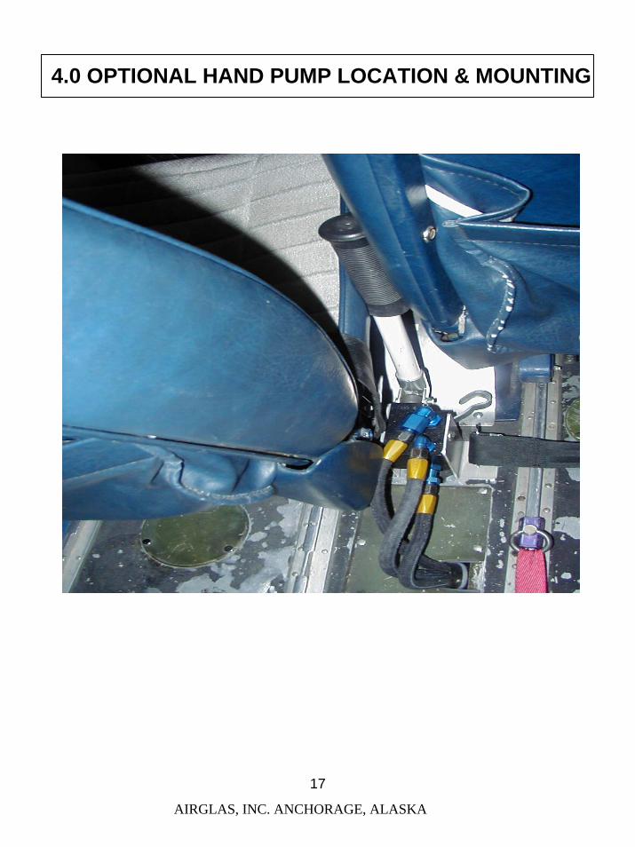
The optional hand pump installation location may vary from aircraft to aircraft. Some will mount at the seatbelt bracket location others may require additional structural enhancement to support the pump. Aircraft with preexisting pumps will tap into the AN824-4D tees or otherwise operate on manual only.
AIRGLAS, INC. ANCHORAGE, ALASKA 14
AIRGLAS, INC. ANCHORAGE, ALASKA
4.0 HYDRAULIC INSTALLATION
15
Emergency
Hand P
ump
ElectricPump
UP
DN DN
UP
UP DNRes.
UP
UP
From R
eservoir
Thru Lightning Holes
DNDNSTATION 48
=
STATION 27 AFT GEARBOX BULKHEAD
STATION 109 BAGGAGE BULKHEAD
STATION 44 BULKHEAD
AIRGLAS, INC. ANCHORAGE, ALASKA
4.0 HYDRAULIC LINE ROUTING
& HYDRAULIC PUMP MOUNTING
16
4.0 OPTIONAL HAND PUMP LOCATION & MOUNTING
AIRGLAS, INC. ANCHORAGE, ALASKA
17
AIRGLAS, INC. ANCHORAGE, ALASKA
5.0 ELECTRICAL INSTALLATION
18
The electrical components must be installed and connected by a certified mechanic in accordance with FAR part 43 and at least CAR 3 regulations. This section describes and depicts the operation and general layout of the system components.
Location of the operating switch & indicator lights.
AIRGLAS, INC. ANCHORAGE, ALASKA
5.0 ELECTRICAL INSTALLATION
19
*SWITCH-UP SKIS-YELLOW
*SWITCH-DOWN WHEELS-GREEN
5.0 ELECTRICAL SCHEMATIC
AIRGLAS, INC. ANCHORAGE, ALASKA
20
BUS 28v DC BREAKER,20 AMPS
SWITCH, 3POSITION
LED YELLOW
LED GREEN LED GREEN
LED YELLOW
HYD. PUMP
PRESSURESWITCHES
UP CIRCUIT
DOWN CIRCUIT
SKI POSITION
WHEEL POSITION
P/N W23-X1A1G-20 P/N MS35059-27
P/N 108BEC32-PLB-1H-08-08-YZ
P/N MS22759/16-14-9
P/N B2191U524V
P/N B2191U724V
1 AMP
P/N B2191U524V
P/N B2191U724V
14 AWG WIRE
MOMENTARY
LH4000 ELECTRICAL SCHEMATIC
SWITCH AND INDICATOR LIGHT OPERATION
The left hand yellow indicator light will illuminate while the skis are in transit to deployment. When the skis are fully deployed, the right hand yellow light will illuminate. When the operator releases the switch, the left hand yellow light will extiguish. The right hand yellow light will remain on as long as the skis are deployed.
When the operator selects the wheel position, the left hand green light will illuminate while the skis are in transit to the retracted position. When the skis are fully retracted the right hand green light will illuminate and stay on as long as the ski is retracted. When the operator releases the switch, the left hand green light will extinguish.
P/N PS80-K2-1166-500-350
AIRGLAS, INC. ANCHORAGE, ALASKA 21
6.0 SKI ATTACHMENT INSTALLATION
This section describes the attachment of the skis to theAircraft. Unlike some skis, with the LH4000 Ski Kit the aircraft requires no jacking or the removal of any parts. Once the sub axles, fittings, brackets, and hydraulics are in place, the aircraft can simply roll up onto the skis. After the skis are in position, the yoke, hydraulic lines and rigging may be attached.
1
2 3
AIRGLAS, INC. ANCHORAGE, ALASKA
6.0 YOKE ATTACHMENT
22
LH3600-5 YOKE ASSY. (OUTBOARD SIDE)
AN12-17A BOLT
AN960-1216 WASHER
NYLON SET SCREW
LH3600-7 STUB AXLE
AF1441003-1 STEEL AXLE
BRAKE TORQUE PLATE
AXLE SHIMS
LH3600-6 FLANGE
CESSNA GEAR LEGNAS145-41 BOLT
NAS146-42 BOLT
AN960-1216 WASHER
LH3600-5 YOKE ASSY. (INBOARD SIDE)
AN12-17A BOLT
TORQUE TO ~ 70 FT. LBS.
AN363-624 or
MS21042 -6 NUT
Torque 200-250 in. lbs.
AN363-524 or
MS21042-5 NUT
Torque 120-145 in. lbs.
This is the layout and relationship between the yoke, the stub axles, and the landing gear leg.Torque values must be adhered to.
AIRGLAS, INC. ANCHORAGE, ALASKA
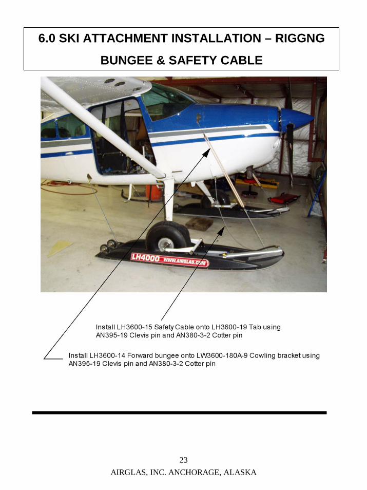
6.0 SKI ATTACHMENT INSTALLATION – RIGGNG
BUNGEE & SAFETY CABLE
23
THIS PAGE, INTENTIONALLY LEFT BLANK
AIRGLAS, INC. ANCHORAGE, ALASKA
24
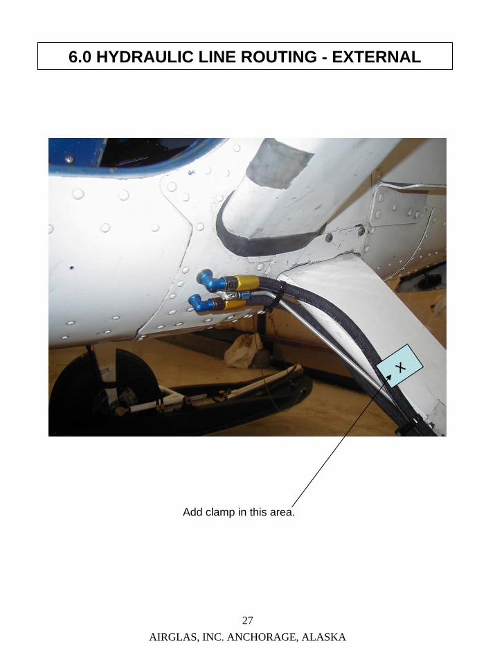
6.0 HYDRAULIC LINES - EXTERNAL
Routing and securing of external hydraulic lines will be explained in this section. It is necessary to install and secure the owner supplied hydraulic lines to the fuselage and the gear legs.1. The gear legs will need additional brake-line clamps bonded to the legs similar
to the factory clamps. The location of the clamps are shown in photos on the next two pages .
2. The leg will have to be prepped in these areas for bonding of the clamps.a. Tape off an area the same size as the clamp on both sides of the leg.b. Rough-up the surface with 80 grit sandpaper inside the taped area.
Remove any corrosion, loose paint, grease, oil, etc.c. Slightly rough-up the inner surface of the clamps.d. Mix and apply Scotch Weld 3M 2216 B/A grey epoxy to the leg and to the
inside of the clamp.e. Push the clamp onto the leg and wipe off the excess with acetone.f. Tape the clamp to the leg to prevent any creep wile curing.g. Allow to cure for 24 hours at room temp, before employing the clamps.h. Follow these steps for all 4 locations on the gear leg. Remove tape when
finished.i. If the preexisting brake line clamps are loose, it is recommended that they
be re-secured in the same fashion. 3. Attach the hose ends to the AN833-4D fittings on the fuselage and to the
AN832-4D fittings on the skis.4. Make sure that there are no twists in the hoses and that they travel in sweeping
arcs.5. Route the lines along the trailing edge of the gear leg.6. Bend the tangs on the added brake line clamps with a duckbill pliers, until they
just make contact with the leg.7. Attach lines to clamps as shown in the photo with Thomas & Betts TY527MX
Ty-Wraps.8. Check for ample slack at lower end of hoses to allow motion of the ski without
pulling on the hoses.9. Cycle skis in both directions when finished and check for leaks at the fitting
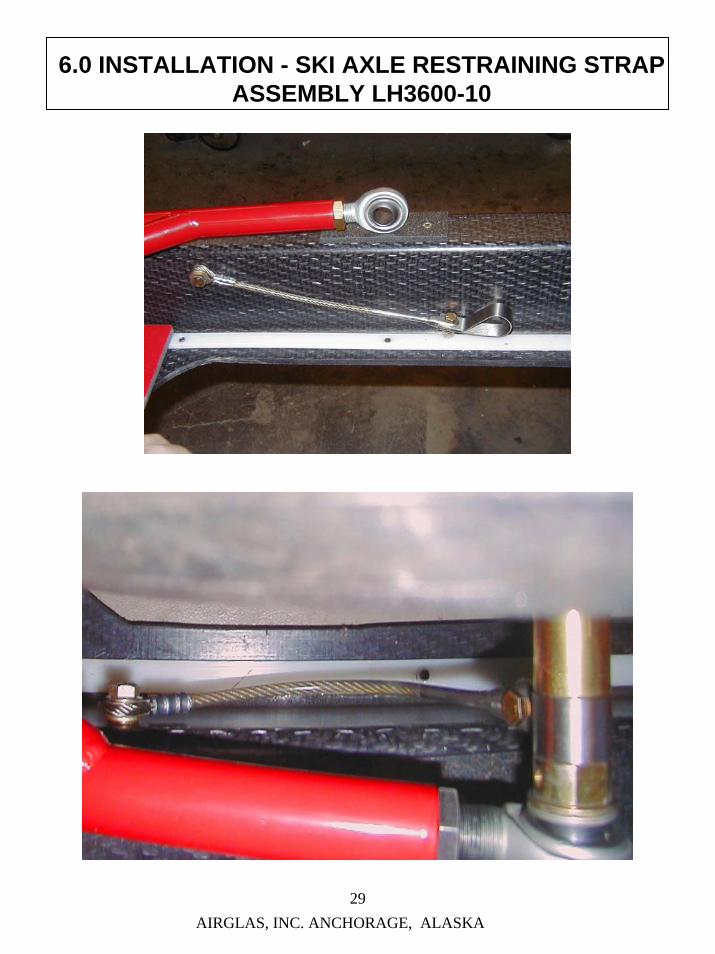
The Ski Axle Restraining Strap Assembly is intended to keep the Yoke Assembly (LH3600-5) from traveling over-center in the unlikely event of a rigging failure. During normaloperations of the ski this component does no work. It is important upon installation of the ski to attach this part to the ski and to the Stub Axle (LH3600-7). The clamp end is held in place with an AN4-7A Bolt, two AN960-4 Washers and an AN365-428 Nut. (This end must be allowed to pivot on the axle.) The pivoting attach point is held to the ski by an AN6-10A Bolt. When this bolt is installed it is imperative that it is installed with REMOVEABLEthread locking compound. (This part must be allowed to pivot.) Failure to follow these instructions may result in damage to the skis.
.
WARNINGAircraft shall not be operated without the (LH3600-10) Ski Axle Restraining Strap Assembly properly installed. Operation without the (LH3600-10) properly installed will be considered an unapproved ski installation.
1. DO NOT – Push or Pull on skis to move aircraft. 2. DO NOT – Subject to flame or high heat. 3. DO NOT – Attempt to jack aircraft with skis installed. 4. DO NOT – Subject to harsh solvents or caustic chemicals.5. DO NOT – Use skis as a tie down for the aircraft. 6. DO NOT – Attempt to change a tire with the skis installed. 7. DO NOT – Use standard wheel chocks with skis installed.
MAINTENANCE OPERATIONAL CHECKS
10-14 Check (10 hour or 14 day inspection)1. CHECK – Bungees, cables, clevis pins, cotter pins, nuts, bolts and attach fittings for
security.
2. CHECK – LH4000 Ski Kit for cracks, excessive wear,fractures and abrasions.
INSPECTION CRITERIA
100-Annual (100 hour or Annual inspection)1. INSPECT – The LH4000 Ski Kit for:
Excessive cracks, wear, fractures and abrasions. Inspect the bottom for cracks, scratches and excess wear. If damaged consult manufacturer.
2. INSPECT – The LH3600-15 safety cable and LH3600-14 bungees for integrity and fraying.The LH3600-13 check cable for cracks, wear, fraying and abrasions. The LH3600-5 yoke assembly for integrity, cracks, dents and corrosion.
3. INSPECT – The main landing gear ski axle assemblies for cracks, fractures and thread integrity and corrosion.
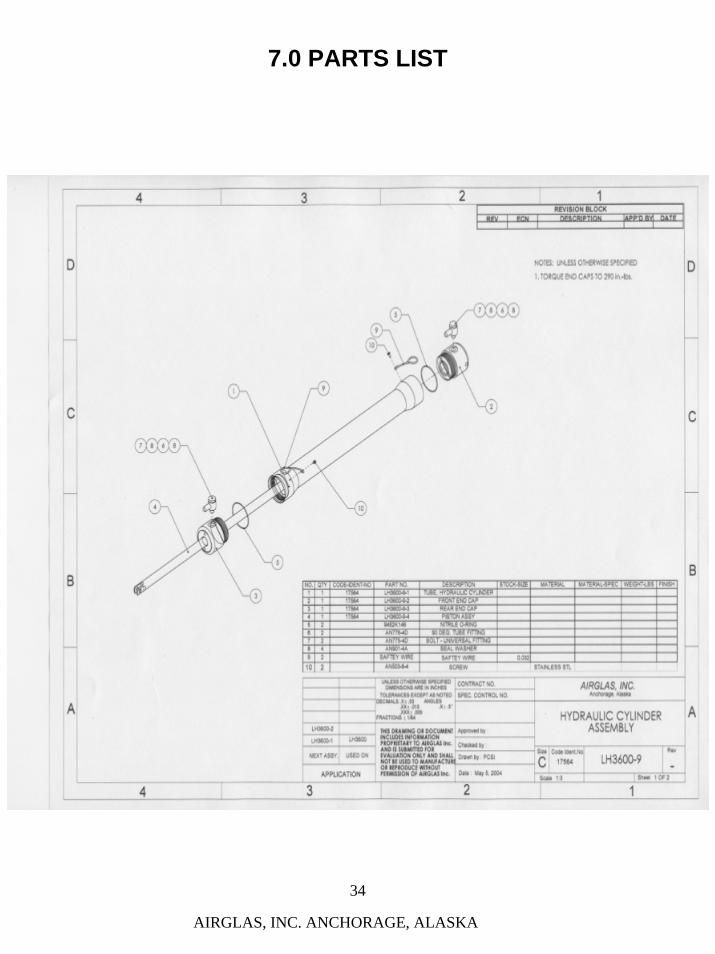
4. INSPECT – The LH3600-9 hydraulic cylinder. Disassemble and clean the components, inspect the o-rings for integrity.
AIRGLAS, INC. ANCHORAGE, ALASKA
8.0 MAINTENANCE - INSTRUCTIONS
36
TOP SURFACE MAINTENANCE
The surface of the ski has a very durable plastic coating that is not affected by gas or oil or environmental conditions. It may be brightened up with rubbing compound and wax occasionally but should not require painting.
BOTTOM SURFACE MAINTENANCE
The UHMW bases are very resistant to damage from abrasion and scuffing. The bases will need no maintenance outside of an occasional waxing.
TYPES OF POSSIBLE DAMAGE
1. Negligible damagea. Small nicks, scratches or abraded areas in top or bottom of ski.
2. Repairable damagea. Cracks or Fractures – Airglas should be consulted on repairs in this area.b. Delamination – Airglas should be consulted on repairs in this area.c. Abrasion – Bottom wear due to contact with rocks etc., bottom surface worn
through to fibers.d. Major bottom damage – Complete new or partial bottom may be factory installed.
3. Damage necessitating replacement a. Major damage in area of ski fittings or hydraulic cylinder bracket.b. Damage to ski structure i.e. The truss area of the top of the ski or in the tail wheel
area. This could be a combination of cracks, fractures delamination, and demolished sections. This type of damage would likely be caused in a crash or accident.
8.0 MAINTENANCE INSTRUCTIONS
SKI ASSEMBLY: The LH4000 Ski has several mechanical aspects to it; the Yoke Assembly, the Door Assembly, the Tail Wheel Bracket and the Rigging components.
1. Yoke Assemblya. The Yoke Assembly P/N (LH3600-5) shall have light grease applied to the Yoke
Buckets P/N (LH3600-5-4) every 25 hours. The Rod Ends P/N (CM-12) shall be lightly oiled every 25 hours.
b. Inspect the attaching bolts P/N (AN12-17A) x2 and (AN5-7A) x12 for corrosion, fretting and proper torque every 25 hours.
c. Inspect the Retaining Rod P/N (LH3600-5-5) attaching nuts for corrosion, fretting and proper torque every 25 hours.
d. Inspect the Ski Axle Restraining Strap Assy. P/N (LH3600-10) for FREEDOM OF MOVEMENT AND SECURITY . The (AN6-10A) Bolt shall be installed with REMOVABLE thread locking compound on the threads.
WARNING: The aircraft shall not be operated without the Ski Axle Restraining Strap Assy. P/N (LH3600-10) installed properly on the skis. Failure to comply with the instructions laid out in this manual will be considered an unapproved installation.
2. Door Assemblya. The Door Assy. P/N (LH3600-8) shall be inspected for wear, deformation, loose
hardware and delaminations.b. The guides and slides should be lubricated with silicone spray at each preflight.
3. The Tail Wheel Bracketa. The Tail Wheel Bracket P/N (LH3600-12) will require greasing annually.b. Inspect for excess wear of the tire and looseness of the wheel bearings at each preflight.c. Inspect attaching hardware for corrosion and security at each preflight.
4. RiggingRigging components shall be inspected for fraying, chafing, kinking and security of hardware, tabs and fittings at each preflight.
AIRGLAS, INC. ANCHORAGE, ALASKA 37
8.0 MAINTENANCE - INSTRUCTIONS
CONTINUED
HYDRAULIC SYSTEM: The hydraulic system is a closed system that should require very little maintenance. Upon initial installation or at any time the lines have been disconnected, the system will need to be purged of air. The OILDYNE pump is a self bleeding pump and requires no special tools. It can be accomplished be one person in the field. Service Steps: 1. Tighten and secure all fittings and lines. 2. Remove the filler cap from the reservoir and top off with (Texaco 5606) or the equivalent of hydraulic fluid. 3. Cycle ski to full travel in both directions until surging stops. Be sure to monitor the fluid level when cycling. When the level reaches ¼ full, add more fluid and top off. This may require several cycles and re-topping of fluid. CAUTION Aircraft will move forward when door closes and rearward when the door opens. Allow ample clearance when cycling the skis. 4. Check the fluid level and look for leaks at the fittings and at both ends of the cylinders at each
preflight. 5. Inspect entire system for security and leaks each 100 hours. ELECTRICAL SYSTEM: The electrical system requires inspection every 500 hours or at annual. 1. Inspect for chafing and wearing of wires through lightening holes, near control cables and fluid
carrying lines. 2. Inspect for loose terminals and solder joints at the circuit breaker, switch, pump-motor, and
indicator lights. 3. If the circuit breaker trips during use, cease operations and inspect system.
Any unresolved questions, problems or defects should be directed to the manufacturer