Installing the Model 3500 Rack Extension Step 1 Dismount the Model RFT9739 from the rack To dismount the Model RFT9739 from the rack: • Switch off power to the Model RFT9739. • Disconnect the power supply wires. - If using DC power, the power supply wires are connected to CN2 pins Z32 and D32. - If using AC power, the power supply wires are connected to CN3. • Disconnect the ground wire from the grounding lug (and from additional I.S. grounding lugs, if present). • Loosen the captive screws that secure the Model RFT9739 front panel to the rack • Slide the transmitter out of the subrack. Step 2 Attach the rack extension to the Model 3500 To attach the rack extension: 1. Align the pins on the back of the Model 3500 with the inward side of the rack extension. 2. Carefully slide the pins into the matching connectors on the extension. 3. Use the three spring-loaded screws to secure the extension to the Model 3500 (Figure 1). 4. Flip the red power source switch to AC or DC to match your power supply (Figure 2). P/N 20003841, Rev. AA September 2005
Transcript
Installing the Model 3500 Rack Extension
Step 1 Dismount the Model RFT9739 from the rack
To dismount the Model RFT9739 from the rack:
• Switch off power to the Model RFT9739.
• Disconnect the power supply wires.
- If using DC power, the power supply wires are connected to CN2 pins Z32 and D32.
- If using AC power, the power supply wires are connected to CN3.
• Disconnect the ground wire from the grounding lug (and from additional I.S. grounding lugs, if present).
• Loosen the captive screws that secure the Model RFT9739 front panel to the rack
• Slide the transmitter out of the subrack.
Step 2 Attach the rack extension to the Model 3500To attach the rack extension:
1. Align the pins on the back of the Model 3500 with the inward side of the rack extension.
2. Carefully slide the pins into the matching connectors on the extension.
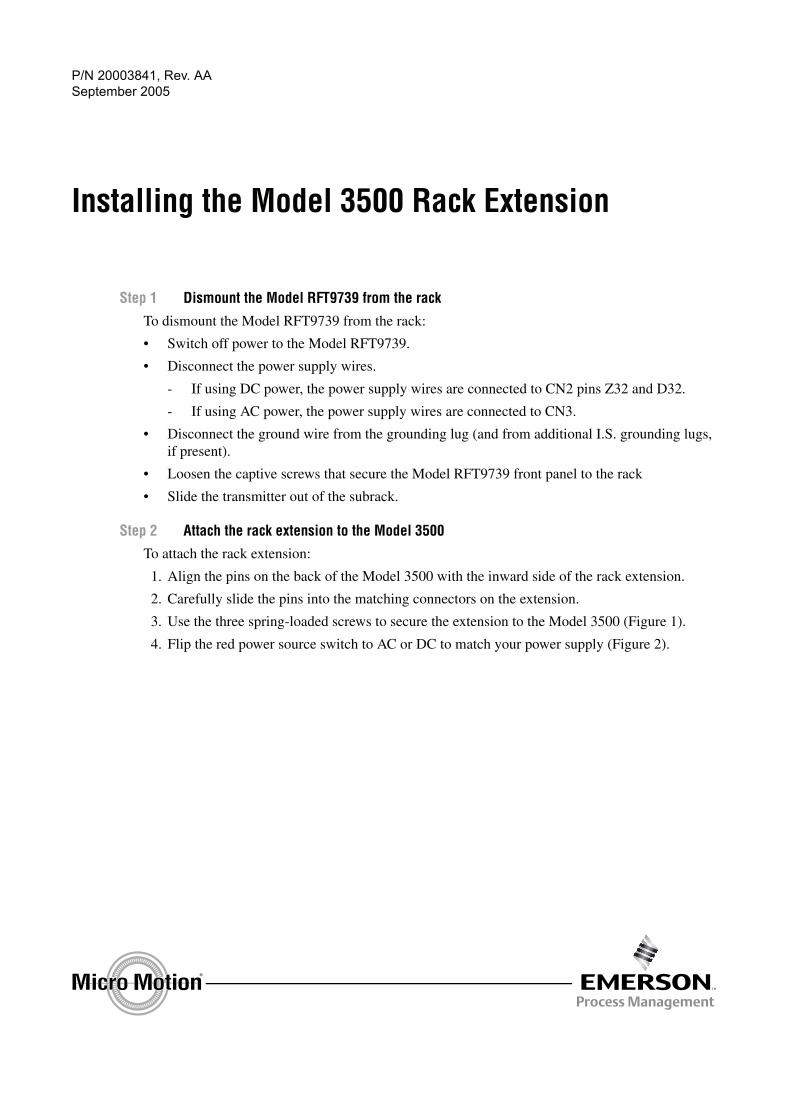
3. Use the three spring-loaded screws to secure the extension to the Model 3500 (Figure 1).
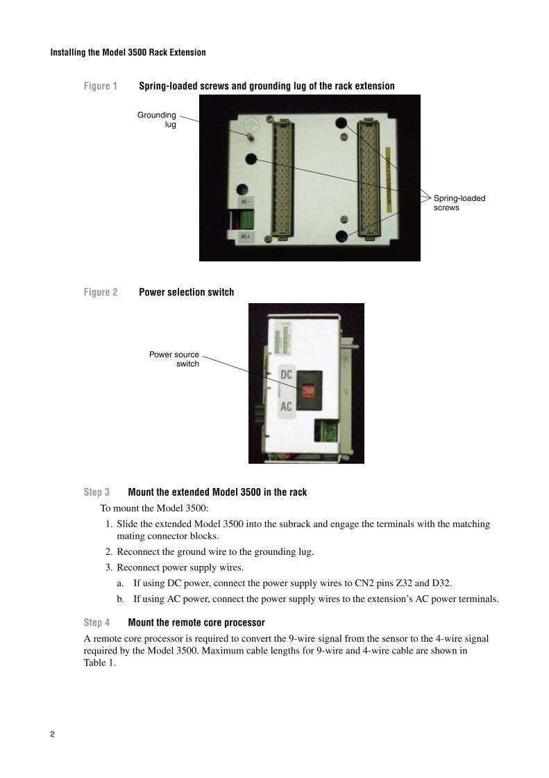
4. Flip the red power source switch to AC or DC to match your power supply (Figure 2).
P/N 20003841, Rev. AASeptember 2005
Installing the Model 3500 Rack Extension
2
Figure 1 Spring-loaded screws and grounding lug of the rack extension
Figure 2 Power selection switch
Step 3 Mount the extended Model 3500 in the rackTo mount the Model 3500:
1. Slide the extended Model 3500 into the subrack and engage the terminals with the matching mating connector blocks.
2. Reconnect the ground wire to the grounding lug.
3. Reconnect power supply wires.
a. If using DC power, connect the power supply wires to CN2 pins Z32 and D32.
b. If using AC power, connect the power supply wires to the extension’s AC power terminals.
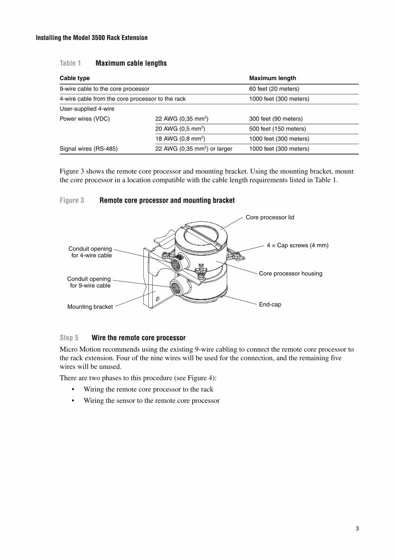
Step 4 Mount the remote core processorA remote core processor is required to convert the 9-wire signal from the sensor to the 4-wire signal required by the Model 3500. Maximum cable lengths for 9-wire and 4-wire cable are shown in Table 1.
Spring-loaded screws
Groundinglug
Power sourceswitch
Installing the Model 3500 Rack Extension
3
Figure 3 shows the remote core processor and mounting bracket. Using the mounting bracket, mount the core processor in a location compatible with the cable length requirements listed in Table 1.
Figure 3 Remote core processor and mounting bracket
Step 5 Wire the remote core processor
Micro Motion recommends using the existing 9-wire cabling to connect the remote core processor to the rack extension. Four of the nine wires will be used for the connection, and the remaining five wires will be unused.
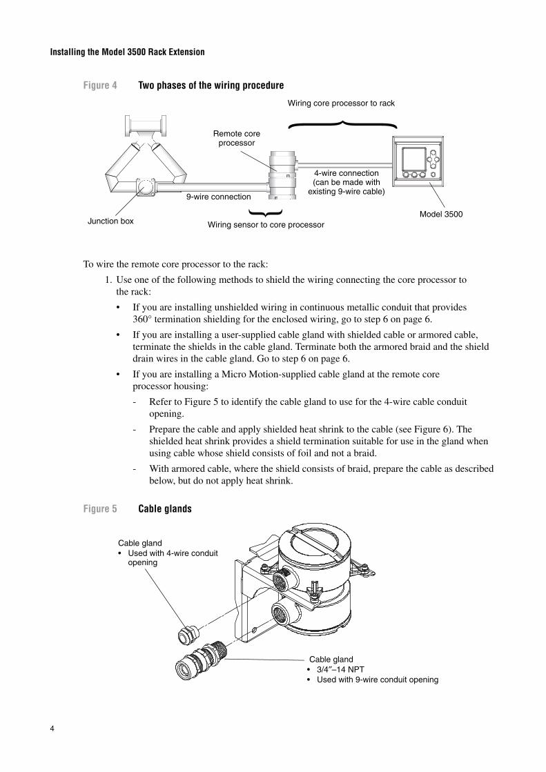
There are two phases to this procedure (see Figure 4):
• Wiring the remote core processor to the rack
• Wiring the sensor to the remote core processor
Table 1 Maximum cable lengths
Cable type Maximum length
9-wire cable to the core processor 60 feet (20 meters)
4-wire cable from the core processor to the rack 1000 feet (300 meters)
Signal wires (RS-485) 22 AWG (0,35 mm2) or larger 1000 feet (300 meters)
End-capMounting bracket
Core processor lid
Core processor housing
Conduit openingfor 4-wire cable
Conduit openingfor 9-wire cable
4 × Cap screws (4 mm)
Installing the Model 3500 Rack Extension
4
Figure 4 Two phases of the wiring procedure
To wire the remote core processor to the rack:
1. Use one of the following methods to shield the wiring connecting the core processor to the rack:
• If you are installing unshielded wiring in continuous metallic conduit that provides 360° termination shielding for the enclosed wiring, go to step 6 on page 6.
• If you are installing a user-supplied cable gland with shielded cable or armored cable, terminate the shields in the cable gland. Terminate both the armored braid and the shield drain wires in the cable gland. Go to step 6 on page 6.
• If you are installing a Micro Motion-supplied cable gland at the remote core processor housing:
- Refer to Figure 5 to identify the cable gland to use for the 4-wire cable conduit opening.
- Prepare the cable and apply shielded heat shrink to the cable (see Figure 6). The shielded heat shrink provides a shield termination suitable for use in the gland when using cable whose shield consists of foil and not a braid.
- With armored cable, where the shield consists of braid, prepare the cable as described below, but do not apply heat shrink.
Figure 5 Cable glands
{{Wiring core processor to rack
Wiring sensor to core processor
Remote core processor
4-wire connection (can be made with
existing 9-wire cable)9-wire connection
Junction boxModel 3500
Cable gland• Used with 4-wire conduit
opening
Cable gland• 3/4″–14 NPT• Used with 9-wire conduit opening
Installing the Model 3500 Rack Extension
5
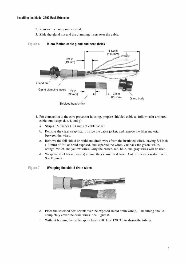
2. Remove the core processor lid.
3. Slide the gland nut and the clamping insert over the cable.
Figure 6 Micro Motion cable gland and heat shrink
4. For connection at the core processor housing, prepare shielded cable as follows (for armored cable, omit steps d, e, f, and g):
a. Strip 4 1/2 inches (114 mm) of cable jacket.
b. Remove the clear wrap that is inside the cable jacket, and remove the filler material between the wires.
c. Remove the foil shield or braid and drain wires from the insulated wires, leaving 3/4 inch (19 mm) of foil or braid exposed, and separate the wires. Cut back the green, white, orange, violet, and yellow wires. Only the brown, red, blue, and gray wires will be used.
d. Wrap the shield drain wire(s) around the exposed foil twice. Cut off the excess drain wire. See Figure 7.
Figure 7 Wrapping the shield drain wires
e. Place the shielded heat shrink over the exposed shield drain wire(s). The tubing should completely cover the drain wires. See Figure 8.
f. Without burning the cable, apply heat (250 °F or 120 °C) to shrink the tubing.
4 1/2 in(114 mm)
3/4 in(19 mm)
7/8 in (22 mm) 7/8 in
(22 mm)
Shielded heat shrink
Gland body
Gland nut
Gland clamping insert
Installing the Model 3500 Rack Extension
6
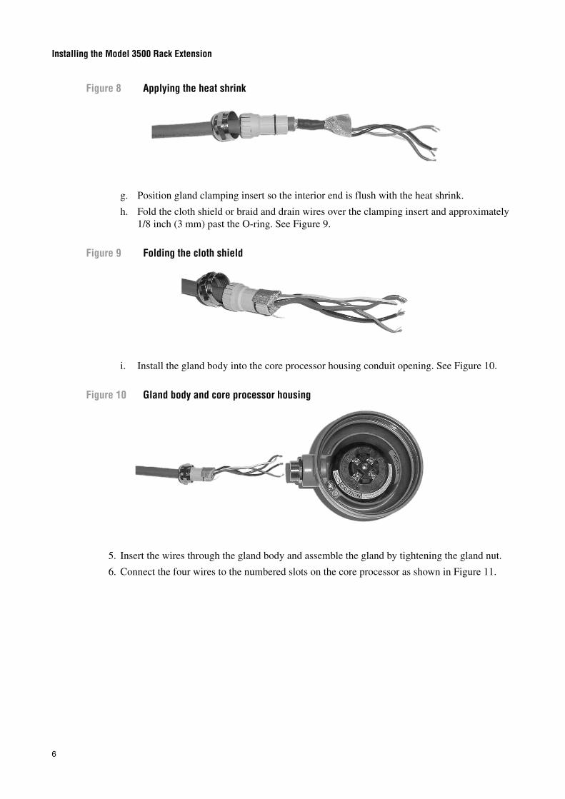
Figure 8 Applying the heat shrink
g. Position gland clamping insert so the interior end is flush with the heat shrink.
h. Fold the cloth shield or braid and drain wires over the clamping insert and approximately 1/8 inch (3 mm) past the O-ring. See Figure 9.
Figure 9 Folding the cloth shield
i. Install the gland body into the core processor housing conduit opening. See Figure 10.
Figure 10 Gland body and core processor housing
5. Insert the wires through the gland body and assemble the gland by tightening the gland nut.
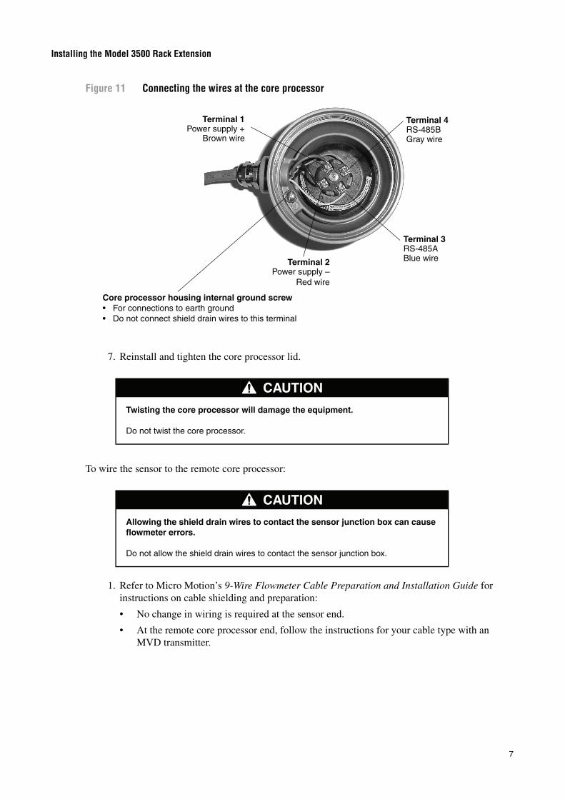
6. Connect the four wires to the numbered slots on the core processor as shown in Figure 11.
Installing the Model 3500 Rack Extension
7
Figure 11 Connecting the wires at the core processor
7. Reinstall and tighten the core processor lid.
To wire the sensor to the remote core processor:
1. Refer to Micro Motion’s 9-Wire Flowmeter Cable Preparation and Installation Guide for instructions on cable shielding and preparation:
• No change in wiring is required at the sensor end.
• At the remote core processor end, follow the instructions for your cable type with an MVD transmitter.
CAUTION
Twisting the core processor will damage the equipment.
Do not twist the core processor.
CAUTION
Allowing the shield drain wires to contact the sensor junction box can cause flowmeter errors.
Do not allow the shield drain wires to contact the sensor junction box.
Terminal 1Power supply +
Brown wire
Terminal 2Power supply –
Red wire
Terminal 3RS-485ABlue wire
Terminal 4RS-485BGray wire
Core processor housing internal ground screw• For connections to earth ground• Do not connect shield drain wires to this terminal
Installing the Model 3500 Rack Extension
8
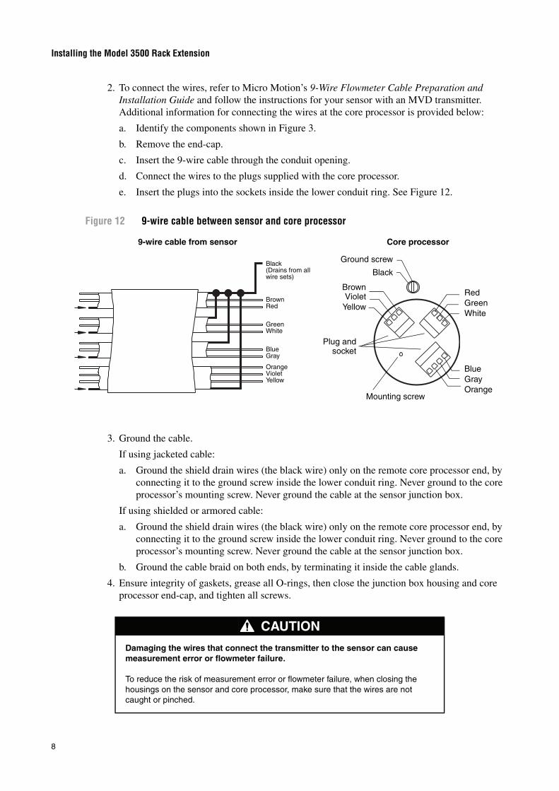
2. To connect the wires, refer to Micro Motion’s 9-Wire Flowmeter Cable Preparation and Installation Guide and follow the instructions for your sensor with an MVD transmitter. Additional information for connecting the wires at the core processor is provided below:
a. Identify the components shown in Figure 3.
b. Remove the end-cap.
c. Insert the 9-wire cable through the conduit opening.
d. Connect the wires to the plugs supplied with the core processor.
e. Insert the plugs into the sockets inside the lower conduit ring. See Figure 12.
Figure 12 9-wire cable between sensor and core processor
3. Ground the cable.
If using jacketed cable:
a. Ground the shield drain wires (the black wire) only on the remote core processor end, by connecting it to the ground screw inside the lower conduit ring. Never ground to the core processor’s mounting screw. Never ground the cable at the sensor junction box.
If using shielded or armored cable:
a. Ground the shield drain wires (the black wire) only on the remote core processor end, by connecting it to the ground screw inside the lower conduit ring. Never ground to the core processor’s mounting screw. Never ground the cable at the sensor junction box.
b. Ground the cable braid on both ends, by terminating it inside the cable glands.
4. Ensure integrity of gaskets, grease all O-rings, then close the junction box housing and core processor end-cap, and tighten all screws.
CAUTION
Damaging the wires that connect the transmitter to the sensor can cause measurement error or flowmeter failure.
To reduce the risk of measurement error or flowmeter failure, when closing the housings on the sensor and core processor, make sure that the wires are not caught or pinched.
BrownRed
GreenWhite
BlueGray
OrangeVioletYellow
Black(Drains from allwire sets)
Plug andsocket
Mounting screw
BlueGrayOrange
RedGreenWhite
BrownViolet
Yellow
Ground screw
Black
9-wire cable from sensor Core processor
Installing the Model 3500 Rack Extension
9
Step 6 Ground the remote core processor Ground the remote core processor according to applicable local standards using either the internal or external grounding screw.
If national standards are not in effect, follow these grounding guidelines:
• Use copper wire, 14 AWG (2,5 mm2) or larger wire size, for grounding.
• Keep all ground leads as short as possible, less than 1 Ω impedance.
• Connect ground leads directly to earth, or follow plant standards.
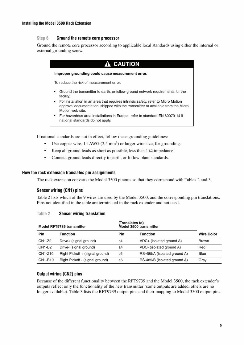
How the rack extension translates pin assignmentsThe rack extension converts the Model 3500 pinouts so that they correspond with Tables 2 and 3.
Sensor wiring (CN1) pins
Table 2 lists which of the 9 wires are used by the Model 3500, and the corresponding pin translations. Pins not identified in the table are terminated in the rack extender and not used.
Output wiring (CN2) pins
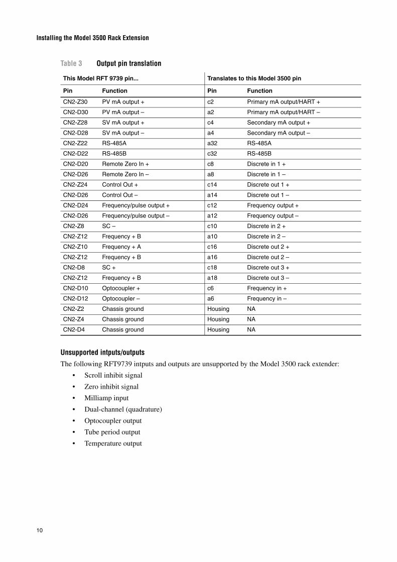
Because of the different functionality between the RFT9739 and the Model 3500, the rack extender’s outputs reflect only the functionality of the new transmitter (some outputs are added, others are no longer available). Table 3 lists the RFT9739 output pins and their mapping to Model 3500 output pins.
CAUTION
Improper grounding could cause measurement error.
To reduce the risk of measurement error:
• Ground the transmitter to earth, or follow ground network requirements for the facility.
• For installation in an area that requires intrinsic safety, refer to Micro Motion approval documentation, shipped with the transmitter or available from the Micro Motion web site.
• For hazardous area installations in Europe, refer to standard EN 60079-14 if national standards do not apply.
Table 2 Sensor wiring translation
Model RFT9739 transmitter(Translates to) Model 3500 transmitter
Wire ColorPin Function Pin Function
CN1-Z2 Drive+ (signal ground) c4 VDC+ (isolated ground A) Brown
CN1-B2 Drive- (signal ground) a4 VDC- (isolated ground A) Red
CN1-Z10 Right Pickoff + (signal ground) c6 RS-485/A (isolated ground A) Blue
CN1-B10 Right Pickoff - (signal ground) a6 RS-485/B (isolated ground A) Gray
Installing the Model 3500 Rack Extension
10
Unsupported intputs/outputsThe following RFT9739 intputs and outputs are unsupported by the Model 3500 rack extender:
• Scroll inhibit signal
• Zero inhibit signal
• Milliamp input
• Dual-channel (quadrature)
• Optocoupler output
• Tube period output
• Temperature output
Table 3 Output pin translation
This Model RFT 9739 pin... Translates to this Model 3500 pin
Pin Function Pin Function
CN2-Z30 PV mA output + c2 Primary mA output/HART +
CN2-D30 PV mA output – a2 Primary mA output/HART –
CN2-Z28 SV mA output + c4 Secondary mA output +
CN2-D28 SV mA output – a4 Secondary mA output –
CN2-Z22 RS-485A a32 RS-485A
CN2-D22 RS-485B c32 RS-485B
CN2-D20 Remote Zero In + c8 Discrete in 1 +
CN2-D26 Remote Zero In – a8 Discrete in 1 –
CN2-Z24 Control Out + c14 Discrete out 1 +
CN2-D26 Control Out – a14 Discrete out 1 –
CN2-D24 Frequency/pulse output + c12 Frequency output +
CN2-D26 Frequency/pulse output – a12 Frequency output –