Doc. No. APP 067U-02 High Viscosity Material Supply Pump 140 / 125 type series SR140P25-P MODEL No.854557(25×1) SR140P38-P MODEL No.854558(38×1) SR140P50-P MODEL No.854559(50×1) SR140P25-D MODEL No.854560(25×1) SR140P38-D MODEL No.854561(38×1) SR140P50-D MODEL No.854562(50×1) SR125D13 MODEL No.854664(13×1) WARNING Prior to operating this pump, be sure to read this operation manual for safety. After reading the manual, please keep it at hand any time for your quick reference. INSTRUCTION
Transcript
Doc. No. APP 067U-02
High Viscosity Material Supply Pump
140 / 125 type series SR140P25-P MODEL No.854557(25×1) SR140P38-P MODEL No.854558(38×1) SR140P50-P MODEL No.854559(50×1) SR140P25-D MODEL No.854560(25×1) SR140P38-D MODEL No.854561(38×1) SR140P50-D MODEL No.854562(50×1) SR125D13 MODEL No.854664(13×1)
WARNING Prior to operating this pump, be sure to read this operation manual for safety. After reading the manual, please keep it at hand any time for your quick reference.
INSTRUCTION
1/3 - Preface
Thank you very much for purchasing Yamada Pump.
SR140 / 125 series pumps are powered by air and designed for pumping low viscosity grease efficiently as well as high
viscosity. The pump can be mounted on a variety of lift units depending on the intended use.
The pump, if used with a lift and an inductor plate, will work more effectively as a complete unit. The pump unit is able to
pump material from a container efficiently, wiping off the material on the inner wall of a container. Due to this function, you can
save the effort of replacing or filling a container.
- For Safe Operation
This document describes the items that are important for the user to operate this product safety, correctly, and efficiently.
Before operating this product, read this manual thoroughly, in particular, “Warnings and Cautions” at the beginning of this
manual, with a good understanding of its contents. Keep this manual carefully in an easy-to-access place so that the user
may refer to it whenever necessary.
- Warnings and Cautions
To use this product safely, be sure to observe the contents of the following description. In this manual, warnings and cautions
are indicated by using symbols. These symbols are intended to prevent death or serious injury that may be caused to the
operator or those who are around the product and damage that may be caused to the articles that are around the product, as
well as to use the product safely and correctly. Each symbol is indicated and has a meaning as shown below. Read the
description with a good understanding of its contents.
WARNING : This indicates the existence of potential hazard which, if not avoided, will result in death or serious injury.
CAUTION : This indicates the existence of potential hazard which, if not avoided, may result in bodily injury or in physical damage.
To indicate the contents of danger and damage, the following symbols are used together with the above indications.
This symbol indicates an act that is prohibited (prohibition). The concrete contents of prohibition are indicated by the side of the indication.
This symbol indicates the contents that must be observed. The concrete contents of observance are indicated by the side of the indication.
2/3 - Precautions on Use
The following warnings and cautions are very important. Be sure to observe them.
WARNING [Operating condition]
- Read this manual thoroughly before use. For your safety, read and understand all information provided in this manual. If you have lost or damaged your instruction manual, please contact us or our distributor to place an order.
- Restriction on handling Never let anyone operate this unit without understanding this manual.
[Operating method]
- Understand this manual completely before operating the machine. Operators and maintenance personnel are required to read this manual thoroughly before operating or servicing. Do not handle this machine without understanding the instructions.
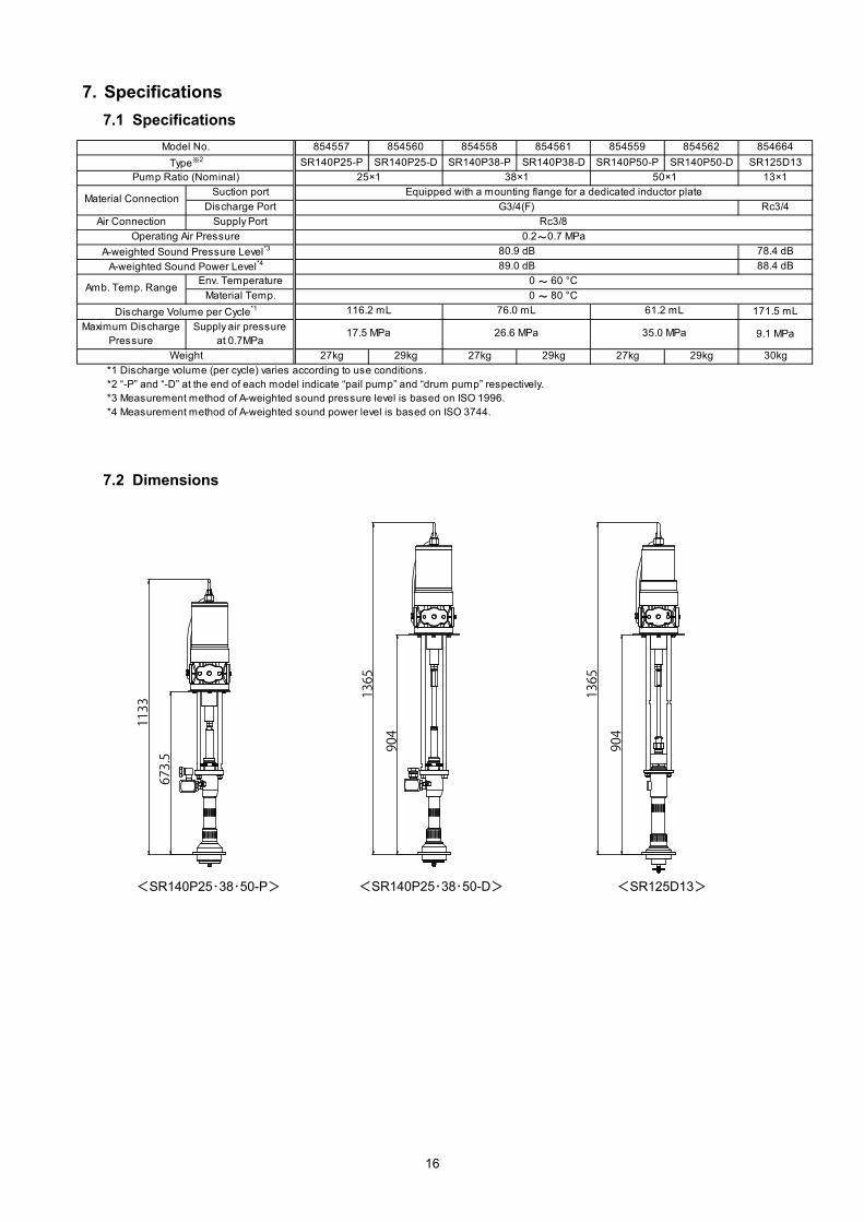
- Do not use inappropriately. Use of the product for any purpose other than those specified in this manual may result in personal injury or property damage. Be sure to use the unit in accordance with the specifications described in “7. Specifications” in this manual.
[Disassembly, maintenance and inspection]
- Shut off air supply. Performing these tasks when air supply is on may cause a sudden movement of the lift or an unexpected discharge of material. Be sure to shut off the air source to stop the machine before servicing.
- No alternation is permitted. Alternating the unit may result in personal injury or product malfunction. Please do not try to alter, modify, or change the machine.
- Some materials can be detrimental to the environment. Be sure to discharge to a container. Never discharge directly to the ground.
- Replacement time for consumables The life of consumables varies depending on operating conditions. Replace a degraded part with a new one.
3/3
CAUTION [Installation and piping]
- Install an emergency stop valve. Attach an emergency stop valve to the air piping (somewhere accessible between the air source and unit) and close this valve in case of emergency.
- Stop operation. If any abnormality is found during operation, immediately stop the machine. Do not restart until the cause has been identified and corrected.
- Shut off air supply. Shut off the air source BEFORE installation and piping.
- Install properly. Install the unit properly according to the requirements for location and material, pressure resistance, and size of hoses and other device, avoiding lift operation failure and pipe leakage or breakage.
- Do not plumb directly. Do not connect the material outlet and piping directly. Attach a flexible tube like a hose to connect the pump to the piping. The pump, if connected directly to the piping, may cause many problems (e.g., noise caused by vibration, damage to the piping, operation failure of the lift, and failure of maintenance).
[Handling]
- In case of emergency Close the emergency stop valve.
- Air pressure to the pump Set the pump air regulator to 0.7MPa or less.
[Shutdown and storage]
- When left unused for a long time (an hour or more) or shutdown In such case, close the air source and open the bleeder valve to release residual pressure inside the pump. (Close the bleeder valve after the residual air and material is removed.) If a drum is not mounted, move the lift to the lower limit and put a plastic bag over the inductor plate to prevent dust.
Table of Contents
- Preface
- For Safe Operation
- Warnings and Cautions
- Precautions on Use
- Table of Contents
1. Part Names 1.1 Part names ········································································································ 1 1.2 Contents of a package ·························································································· 1
3. Preparation of Installation and Operation 3.1 Pump installation ································································································· 2 3.2 Installation of silencer ··························································································· 3 3.3 Connecting suction piping ····················································································· 3 3.4 Connecting suction piping ····················································································· 3 3.5 Discharge piping ································································································· 4 3.6 Air piping ··········································································································· 4 3.7 Preparation for use ······························································································ 4
4. Operating Method 4.1 Description of valve ····························································································· 5 4.2 Solvent cup ········································································································ 5 4.3 Filling delivery piping with material ·········································································· 5 4.4 Operation ·········································································································· 6 4.5 After work ·········································································································· 6
5. Maintenance and Inspection 5.1 Maintenance and inspection ·················································································· 7 5.2 Troubleshooting ·································································································· 8 5.3 Consumables ····································································································· 9 5.4 Design standard use period ··················································································· 10
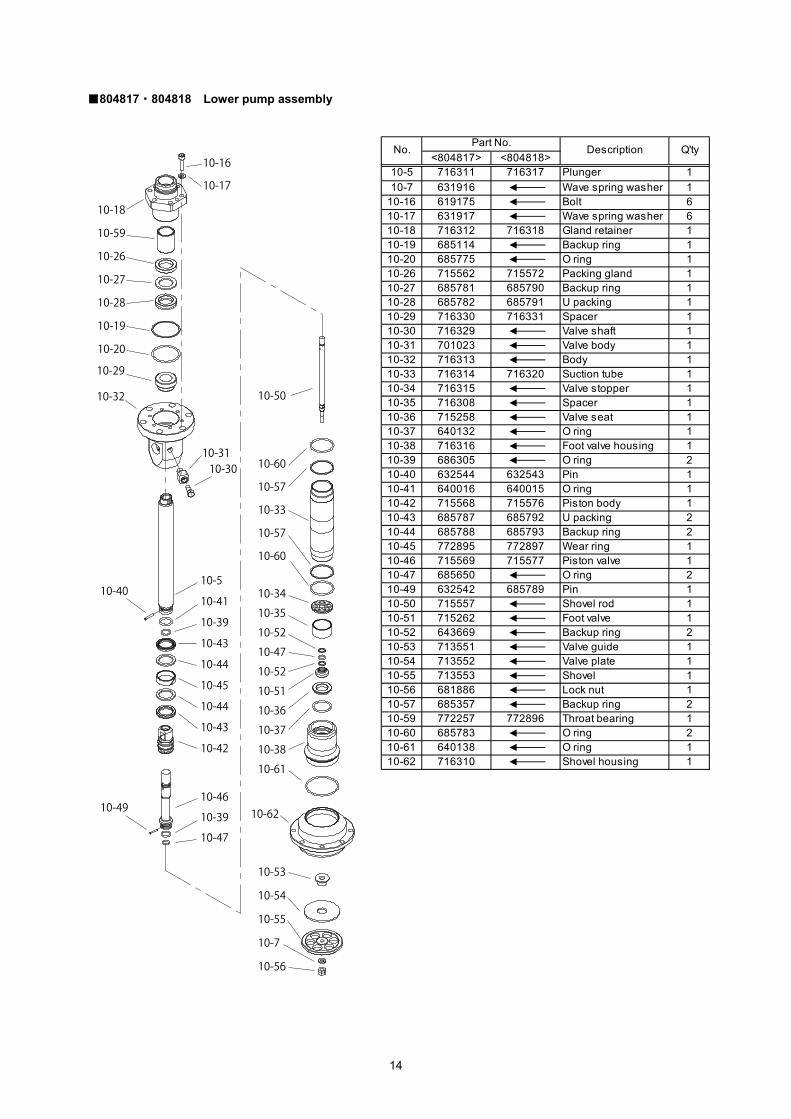
6. Parts Disassembly Drawing and Parts List ····························································· 11
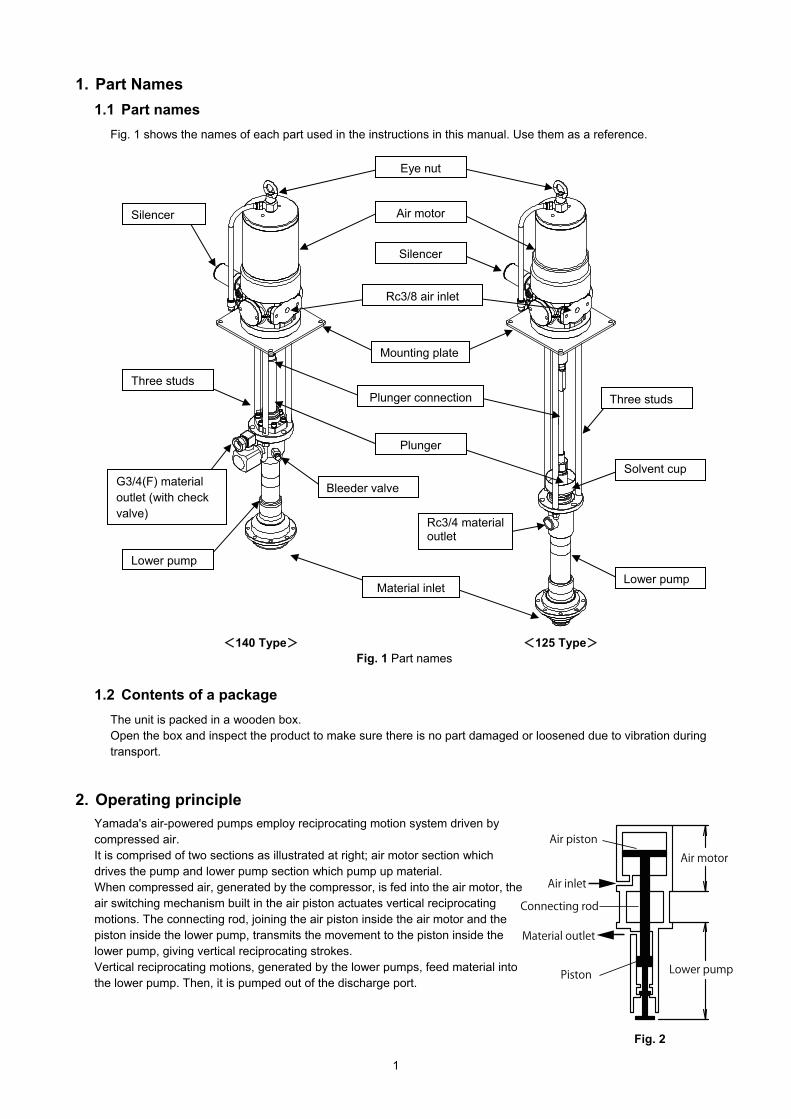
Fig. 1 shows the names of each part used in the instructions in this manual. Use them as a reference.
1.2 Contents of a package
The unit is packed in a wooden box. Open the box and inspect the product to make sure there is no part damaged or loosened due to vibration during transport.
2. Operating principle
Yamada's air-powered pumps employ reciprocating motion system driven by compressed air. It is comprised of two sections as illustrated at right; air motor section which drives the pump and lower pump section which pump up material. When compressed air, generated by the compressor, is fed into the air motor, the air switching mechanism built in the air piston actuates vertical reciprocating motions. The connecting rod, joining the air piston inside the air motor and the piston inside the lower pump, transmits the movement to the piston inside the lower pump, giving vertical reciprocating strokes. Vertical reciprocating motions, generated by the lower pumps, feed material into the lower pump. Then, it is pumped out of the discharge port.
Fig. 2
<140 Type> <125 Type>
Three studs
G3/4(F) material outlet (with check valve)
Lower pump
Silencer
Rc3/8 air inlet
Mounting plate
Plunger connection
Plunger
Air motor
Bleeder valve
Material inlet
Rc3/4 material outlet
Three studs
Lower pump
Solvent cup
Silencer
Eye nut
Fig. 1 Part names
2
3. Preparation of Installation and Operation
<NOTE> If you have purchased a complete pump unit, refer to the instruction manual for the unit for installation, operating method, and other instructions.
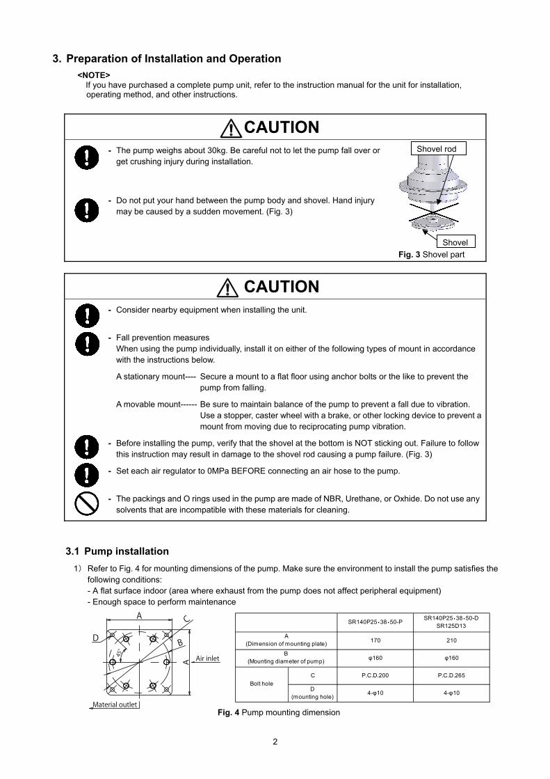
CAUTION - The pump weighs about 30kg. Be careful not to let the pump fall over or
get crushing injury during installation.
- Do not put your hand between the pump body and shovel. Hand injury may be caused by a sudden movement. (Fig. 3)
CAUTION - Consider nearby equipment when installing the unit.
- Fall prevention measures When using the pump individually, install it on either of the following types of mount in accordance with the instructions below.
A stationary mount---- Secure a mount to a flat floor using anchor bolts or the like to prevent the pump from falling.
A movable mount------ Be sure to maintain balance of the pump to prevent a fall due to vibration. Use a stopper, caster wheel with a brake, or other locking device to prevent a mount from moving due to reciprocating pump vibration.
- Before installing the pump, verify that the shovel at the bottom is NOT sticking out. Failure to follow this instruction may result in damage to the shovel rod causing a pump failure. (Fig. 3)
- Set each air regulator to 0MPa BEFORE connecting an air hose to the pump.
- The packings and O rings used in the pump are made of NBR, Urethane, or Oxhide. Do not use any solvents that are incompatible with these materials for cleaning.
3.1 Pump installation
1) Refer to Fig. 4 for mounting dimensions of the pump. Make sure the environment to install the pump satisfies the following conditions: - A flat surface indoor (area where exhaust from the pump does not affect peripheral equipment) - Enough space to perform maintenance
Fig. 4 Pump mounting dimension
Fig. 3 Shovel part
Shovel
Shovel rod
SR140P25・38・50-PSR140P25・38・50-D
SR125D13
170 210
φ160 φ160
C P.C.D.200 P.C.D.265
D(mounting hole)
4-φ10 4-φ10
A(Dimension of mounting plate)
B(Mounting diameter of pump)
Bolt hole
3
2) Lift the pump using the eye nut on the top. Put the mounting plate on a mount. Align the holes on the mounting plate with the screw holes on the mount and secure it using four bolts with wave spring washers.
<Installing on a stationary mount> Secure a mount to the floor using anchor bolts to prevent a fall due to pump vibration.
<Installing on a movable mount> Keep the pump from moving or falling due to pump vibration by securing a mount with a locking device like a stopper.
3.2 Installation of silencer
CAUTION - Each connection is capped. Remove the caps all.
- Wrap sealing tape around the silencer thread to prevent leakage.
Attach the silencer to the pump and secure it using a tool. (Fig. 5) Wrap sealing tape around the silencer thread to prevent leakage.
3.3 Connecting suction piping (connecting pump to inductor plate)
1) Insert the lower part of the pump through the gasket into the inductor plate.
2) Rotate the holes in the gasket and flanged part of the pump to align with the bolt holes in the inductor plate. Insert bolts with wave spring washers through each hole and tighten them securely. Make sure the air release plug is positioned in the front side of the pump facing away from the bleeder valve.
As the pump start operation, the shovel in the suction port starts reciprocating. Do not place any piping equipment in the operating range of the shovel. Refer to Fig. 7 for the operating range of the shovel and mounting dimension for piping. Apply leak prevention, putting a gasket, for example, to the connection between the flange section of the material inlet of the pump and piping.
Bolt
Gasket
Inductor plate
Fig. 6 Connecting pump to inductor plate
Pump
Fig. 7 Operating range of the shovel and mounting dimension for piping
Fig. 5
Silencer
4
3.5 Discharge piping
1) Connect a discharge hose to the pump outlet. Make sure the hose satisfies the following requirements: - Resistant to material being pumped and unaffected by environment - Satisfying the following normal operation pressure:
-13×1 ratio pump: 10MPa or more -25×1 ratio pump: 18MPa or more -38×1 ratio pump: 27MPa or more -50×1 ratio pump: 35MPa or more
- Recommended size: 3/4 inch or more - When mounting the pump on an elevating machine like a lift, be sure to use a flexible hose with an adequate length in order not to be affected by up-and-down movement. - Hose fitting or joint: <140 Type>Connectable to G3/4(F) material outlet, hose union with a 30 degree male seat <125 Type>Connectable to Rc3/4 material outlet
2) Connect the other end of the hose to a delivery pipeline. Attach a valve at the connection between the hose and the piping for maintenance and keep it closed until unit installation is completed.
3.6 Air piping
1) Connect air piping equipment such as an air valve and air regulator to the air inlet of the pump. Attach an emergency stop valve to the air pipe (somewhere accessible between the air source and unit).
2) Select an air supply hose, fitting, and air equipment that satisfy the following requirements. With these devices, connect an air piping and the air inlet of the lift. Be careful not to let the hose get caught on peripheral equipment. - Designed for use with air and unaffected by environment - Normal operation pressure: 0.7MPa or more - Recommended size: 3/8 inch or more - Hose fitting or joint: Connectable to Rc3/8 air inlet - Comfortable hose length for up/down movement of the lift - Flow rate: 1300L/min (ANR) or more
<NOTE> The air regulator controls supply air pressure to the pump. Accordingly, the pump operates efficiently without unnecessary movement and thus the life of the pump can be extended.
3.7 Preparation for use
The pump has been tested using mineral oil before delivery. Please wash inside the pump with appropriate solvent for the material being pumped.
5
4. Operating Method
CAUTION - Keep your face away from the bleeder valve. Material may spurt out together with compressed air.
- Do not exceed the maximum operating pressure of the pump (0.7MPa). Overpressure may cause a product failure resulting in serious personal injury and/or property damage.
- Keep your hand away from the three studs connecting the air motor and lower pump. Fingers can get caught in the reciprocating plunger.
- Keep your face away from the silencer. Compressed air is exhausted at high pressure, causing moisture to freeze leading cause of injuries.
- In case of a pump malfunction or shutdown, refer to “5.2 Troubleshooting” to judge the situation thoroughly and disassemble the pump only as necessary.
- Avoid allowing the pump to run dry as much as possible. The life expectancy of packings will be reduced. The pump runs dry when a container becomes empty. Stop the pump immediately after the material in a container is all gone.
4.1 Description of valve
- Pump Air Regulator (sold separately) Function : Controlling air pressure for pump operation. To operate : Clockwise turn will increase pressure. Counterclockwise turn will decrease pressure.
(It can be locked by pushing the knob in.) Note : The maximum allowable operating pressure of the pump is 0.7MPa. DO NOT exceed this limit. Remark : Discharge pressure can be calculated by multiplying the air pressure by the pump ratio.
- Air Valve, Pump (sold separately) Function : Starting/Stopping the pump. To operate : When the lever is parallel to the pipe, the valve is open. If the lever is perpendicular to the pipe,
the valve is closed. Note : In case of emergency, close the emergency stop valve attached to the air piping instead of this
valve.
4.2 Solvent cup(125 Type only)
1) The pump is equipped with a solvent cup to keep the packing from sticking to the plunger. Shut down the pump and then fill the cup 2/3 full with suitable lubricant or solvent.
2) When lubricant in the cup runs out during operation, shut down the pump first and refill the cup.
4.3 Filling delivery piping with material
1) Open the bleeder valve by turning it 2-3 times for releasing air. 2) Open the air valve for the pump and increase air pressure gradually with the pump air regulator. The pump will
start operating at approx. 0.05MPa. Adjust the pump air regulator to set pump speed to 5-8 seconds per cycle. 3) Air-containing material will be discharged from the bleeder valve. Put a plastic bag over the valve to receive
discharged material. Keep the pump operating until the air inside material is released completely. Then close the bleeder valve by securely tightening it.
4) Close the air valve for the pump and set the pump air regulator to 0MPa.
6
4.4 Operation
1) When filling the delivery piping with material for the first time, the air inside the piping will blow out. Please follow the following procedure. ①Put a plastic bag over the material outlet to receive discharged material. ②Open the valve on the delivery piping. ③Open the air valve for the pump and set the pump air regulator for minimum operating pressure. ④The pump will start discharging material from the outlet. Once the air in the piping is released completely,
close the air valve for the pump and set the pump air regulator to 0MPa. ⑤The pump is now ready for operation.
2) Adjust the pump air regulator to set to the desirable operating pressure. An estimate of the material discharge pressure to the supply air pressure is calculated by “supply air pressure × pump ratio”. (e.g. When operating a 38:1 ratio pump at 0.7MPa supply air pressure, material will be discharged at approx. 26.6MPa.)
<NOTE> Material viscosity changes with seasons. It is recommended to make a note of appropriate pressure for each season.
4.5 After work
CAUTION - After work or when shutting down the unit for a long period, be sure to turn off the air supply source
to disconnect air supply to the pump, and open the valves on the material outlet or gun to release residual pressure inside the pump and piping. Failure to shut off air may cause damage to the hoses and pipes and/or leak in the valves and gun. Any secondary accidents caused by the failure mentioned above are the responsibility of the users.
1) Close the air valve for the pump and set the pump air regulator to 0MPa. 2) Open the valve on the discharge port to release residual pressure on air and material inside the pump and
piping.
7
5. Maintenance and Inspection
CAUTION - Be careful not to allow the pump and lift to accidentally operate during maintenance and inspection.
- When performing maintenance or inspection, notify workers by hanging a sign or other method to keep them from touching the unit.
- Gasoline is a high volatile fuel. Never use it for cleaning of the unit. Risk of fire or explosion may exist.
5.1 Maintenance and inspection
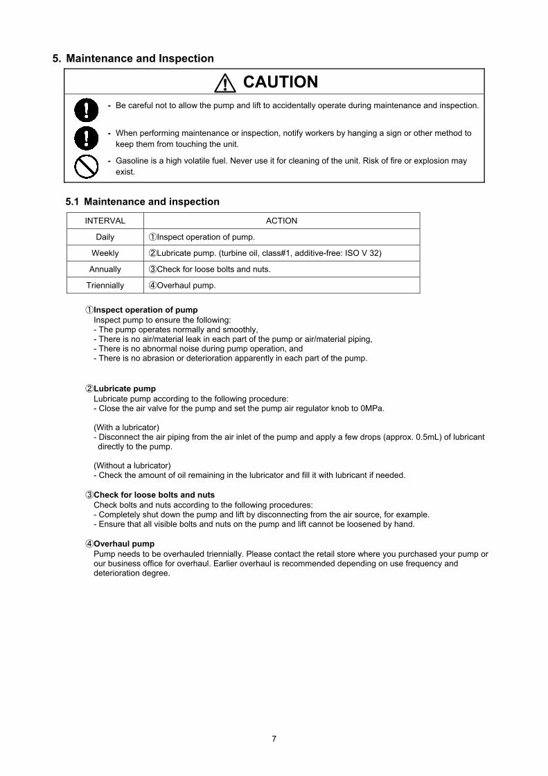
INTERVAL ACTION
Daily ①Inspect operation of pump.
Weekly ②Lubricate pump. (turbine oil, class#1, additive-free: ISO V 32)
Annually ③Check for loose bolts and nuts.
Triennially ④Overhaul pump.
①Inspect operation of pump Inspect pump to ensure the following: - The pump operates normally and smoothly, - There is no air/material leak in each part of the pump or air/material piping, - There is no abnormal noise during pump operation, and - There is no abrasion or deterioration apparently in each part of the pump.
②Lubricate pump Lubricate pump according to the following procedure: - Close the air valve for the pump and set the pump air regulator knob to 0MPa. (With a lubricator) - Disconnect the air piping from the air inlet of the pump and apply a few drops (approx. 0.5mL) of lubricant directly to the pump.
(Without a lubricator) - Check the amount of oil remaining in the lubricator and fill it with lubricant if needed.
③Check for loose bolts and nuts Check bolts and nuts according to the following procedures: - Completely shut down the pump and lift by disconnecting from the air source, for example. - Ensure that all visible bolts and nuts on the pump and lift cannot be loosened by hand.
④Overhaul pump Pump needs to be overhauled triennially. Please contact the retail store where you purchased your pump or our business office for overhaul. Earlier overhaul is recommended depending on use frequency and deterioration degree.
8
5.2 Troubleshooting
If you suspect that you have a problem with your product, consult the table below for some common problems and their solutions. Contact the retail store where you purchased your product or our business office if all else fails.
PROBLEM POSSIBLE CAUSE REMEDY
Compressor is off. Turn on compressor.
Valve on air piping is closed. Open valve.
Air pressure setting is under 0.2MPa. Set air pressure to 0.2MPa or above.
Valve on material outlet is closed. Open valve.
Frost occurs inside silencer. Use dry air.
O ring on sliding part of air piston is worn out.(Air leak occurs from silencer.)
Block (773065) and ball (686271) in valve body (804815) are worn out.
Any parts (e.g. spring, pin) used in switching system in valve body (804815) orair motor (804814 / 804856) are damaged.
Air leak from airmotor
- Fasteners are loose.- O rings and packings are worn out.
- Retighten loose parts.- Replace worn part.
Air leak fromsilencer during
shutdown
- Foreign object is caught between block (773065) and valve seat (716246) in valve body (804815).- Seating part is worn out.
- Remove foreign object.- Replace worn part.
Pump doesn’t runand air leaks from
silencer
- Foreign object is caught between spindle (716299) and valve switcher (832996) in air motor (804814 / 804856).- There exists damage that prevents sliding movement of parts below.
- Remove foreign object.- Replace damaged part.
Pump doesn’t drawmaterial at first time
of operation
Pump operating speed is so fast that lower pump suction cannot keep up withpump movement. (Valve inside lower pump is not working well.)
Set pump speed to 5-8 sec. per cycle untilmaterial is pumped out.
If upward movement of plunger is faster,- seat surface of piston valve is defective (wear of seat surface, inclusion of foreign material) or,- packings are damaged.
If downward movement of plunger is faster,- seat surface of foot valve is defective (wear of seat surface, inclusion of foreign material),- packings are damaged, or- shovel rod is bent.
If downward movement of plunger is faster, operating speed is so fast that lowerpump suction cannot keep up with pump movement. (Vacuum is caused insidelower pump.)
Decrease air pressure until materialcomes out. (This pressure is the upperlimit of normal operating pressure.)
Connecting rod connecting air motor and lower pump is completely separatedfrom air motor. (In this case, parts inside of lower pump may be damaged.)
685616 685782 685791 U packing 1 per unit 5 million cycles
772811 685781 685790 Backup ring 1 per unit 5 million cycles
685618 685787 685792 U packing 2 per unit 5 million cycles
685619 685788 685793 Backup ring 2 per unit 5 million cycles
772812 772895 772897 Wear ring 1 per unit 5 million cycles
685546 - - Packing 1 per unit 5 million cycles
- O ring 1 per unit 5 million cycles
Backup ring 2 per unit 5 million cycles
Valve body assembly
Air motor Assembly
Lower pump assembly
Part No.
Description Q'ty Times of replacement
570145
<804815>
716246
773065
706612
685650
643669
686271
<804814>
640075
640033
5.3 Consumables
Refer to chart under for replacement time for consumables used in the pump. The replacement time should be used only as a guide. Consumption varies depending on use conditions. Also, be sure to replace a part when you find any defect like a leak during operation.
■SR140P25、SR140P38、SR140P50
■SR125D13
Valve seat 1 per unit 10 million cycles
Block 1 per unit 10 million cycles
Spring 1 per unit 10 million cycles
Ball 1 per unit 10 million cycles
O ring 1 per unit 5 million cycles
O ring 1 per unit 5 million cycles
O ring 1 per unit 5 million cycles
Tube 1 per unit 6 years
Plunger 1 per unit 10 million cycles
V packing 6 per unit 3 million cycles
Cylinder 1 per unit 10 million cycles
Revolving stopper 1 per unit 3 million cycles
Packing 2 per unit 3 million cycles
Packing 1 per unit 5 million cycles
Backup ring 2 per unit 5 million cycles
Part No.
Description Q'ty Times of replacement854664(SR125D13)
<804815> Valve body assembly
716246
773065
706612
686271
<804856> Air motor Assembly
640072
640033
640034
570145
<804956> Lower pump assembly
643669
716480
770062
701541
770233
770151
685546
10
5.4 Design standard use period
Design standard use period is established for the product. (See the table below.) Use of the product beyond this period may result in personal injury or property damage. - Pump…10 years
Standard Conditions of Use SR140P25 SR140P38 SR140P50 SR125D13
Application
Season
Temperature
Material being pumped
Supply air pressure
Daily Amount of Material being pumped(Discharge volume)
447L 292L 235L 660L
Operating Days per year
Spring and Fall
Pumping grease
260 days (5 days a week)
0.5MPa
Lithium Soap Grease: No.1
20°C
11
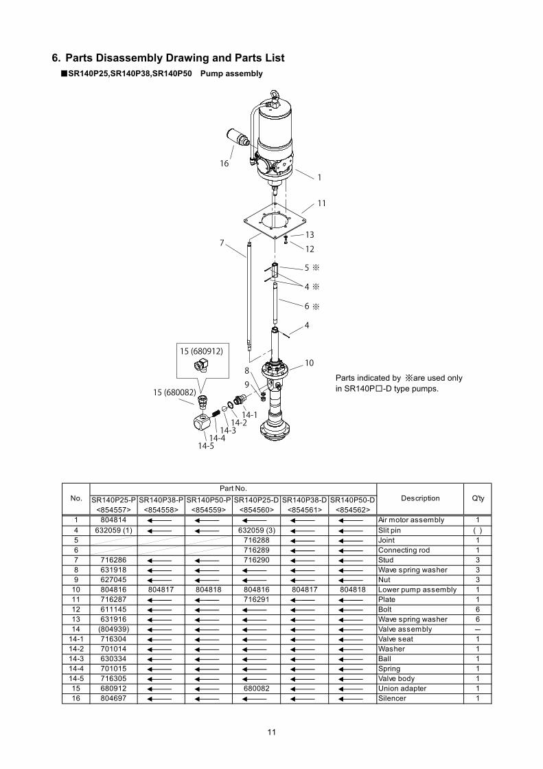
6. Parts Disassembly Drawing and Parts List ■SR140P25,SR140P38,SR140P50 Pump assembly
Parts indicated by ※are used only in SR140P□-D type pumps.
Complete necessary information in the following fax form since your information is necessary to find the cause of the trouble or failure and it enriches our repair services. After filling it, send it to us.
Trouble Information Fax Form
Company name
Name
Address
Department name
Contact information
Tel. ( ) -
Fax. ( ) -
Product name
Model
Duration of use 20 year month to year month
SERIAL No. (LOT No.)
Operation frequency □Continuous
□Intermittent hour/day/week/month
Purchase date Sales outlet
Machine conditions (descriptions of the trouble)
19
9. Limited Warranty
If an abnormality occurs during normal operation in accordance with the operating instructions and other operating cautions within the warranty period (12 months after date of purchase) that can be attributed to a manufacturing defect, the defective parts of this product will be serviced or the product will be replaced free of charge. However, this warranty will not cover compensation for incidental damage or any malfunction listed below.
1. Warranty period
This warranty will be valid for a period of 12 months after the date of purchase. 2. Warranty
If, during the warranty period, any of the material of the genuine parts of this product or the workmanship of this product is found defective, and is so verified by our company, the servicing cost will be fully born by our company.
3. Exclusion
Even during the warranty period, this warranty does not cover the following: 1) Malfunction arising from use of parts other than manufacturer-specified genuine parts
2) Malfunction arising from misuse or operating errors, or lack of storage or maintenance care
3) Malfunction arising from use with a fluid that may cause corrosion, inflation or dissolution of the component
parts of the product
4) Irregularity arising from repair made by other than by our firm, our regional office, dealer or authorized service
personnel
5) Malfunction arising from modification of the product by other than authorized service personnel
6) Wear and tear of parts that must be regularly replaced in the course of normal operation, such as packings,
O-rings
7) Malfunction and/or damage due to transportation, moving or droppage of the product after purchase
8) Malfunction and/or damage due to fire, earthquake, flood or other force majeure
9) Malfunction arising from use of compressed air that contains impurities or excessive moisture, or use of gases
or fluids other than the specified compressed air
10) Malfunction arising from use with a fluid that causes excessive abrasion or use of lubricating oil other than that
specified for this product
Furthermore, this warranty does not cover the rubber parts, or other parts that are subject to wear in normal operation, used in this product and its accessories.
4. Parts
Parts for this product will be kept available for 5 years after discontinuation of production. Once 5 years have elapsed after close of production, availability of parts for this product cannot be guaranteed.
MEMO.
201202 APP067U
Manufactured by
YAMADA CORPORATION
INTERNATIONAL DEPARTMENT
No.1-3, 1-Chome, Minami-Magome, Ohta-ku, Tokyo, 143-8504, Japan