2.5.1 Supply voltage connector ................................................................................. 8 2.5.2 Round socket for bus ....................................................................................... 9 2.5.3 Connector for jog keys ..................................................................................... 9 2.5.4 Electrical grounding .......................................................................................... 9
2.6 Setting the device address baud rate and bus terminating resistors........................... 10 2.7 Start-up ...................................................................................................................... 11 2.8 Modbus ...................................................................................................................... 12
2.8.1 Table of all Holding Registers ..........................................................................13 2.8.2 Table of rated speed and torque values for various models of gears ...............20 2.8.3 Detailed description of status bits ....................................................................22 2.8.4 Detailed description of control bits ...................................................................24
3 Sequence of positioning ............................................................................................ 26
3.1 Positioning run ........................................................................................................... 26 3.2 Positioning run without loop ....................................................................................... 27 3.3 Manual run ................................................................................................................. 27
4 Special features .......................................................................................................... 28
4.1 Speed, acceleration and deceleration ........................................................................ 28 4.2 Maximum starting torque and maximum torque ......................................................... 28 4.3 Response of drive in case of block or manual displacement ...................................... 28 4.4 Calculating the absolute physical position .................................................................. 29 4.5 Using actual value assessment factors to set the spindle pitch .................................. 31 4.6 Drag error .................................................................................................................. 31 4.7 Abort run when the master fails ................................................................................. 31 4.8 Optional: Manual run using external keys (jog key mode) .......................................... 31 4.9 Devices with optional snap brake ............................................................................... 33 4.10 Devices with optional holding brake ........................................................................... 34 4.11 Reference runs .......................................................................................................... 35 4.12 Reverse drive ............................................................................................................ 35
5 Technical Data ............................................................................................................ 36
5.1 Ambient conditions .................................................................................................... 36 5.2 Electrical data ............................................................................................................ 36 5.3 Physical data ............................................................................................................. 37
6 Certificate of Conformity ............................................................................................ 38
Instruction Manual PSx3xxMod
3
Purpose of instruction manual
This instruction manual describes the features of the PSx3xxMod positioning system and provides guidelines for its use. Improper use of these devices or failure to follow these instructions may cause injury or equipment damage. Every person who uses the devices must therefore read the manual and understand the possible risks. The instruction manual, and in particular the safety precautions contained therein, must be followed carefully. Contact the manufacturer if you do not understand any part of this instruction manual. Handle this manual with care:
It must be readily available throughout the lifecycle of the devices.
It must be provided to any individuals who assume responsibility for operating the device at a later date.
It must include any supplementary materials provided by the manufacturer. The manufacturer reserves the right to continue developing this device model without documenting such development in each individual case. The manufacturer will be happy to determine whether this manual is up-to-date.
Conformity
This device is state of the art. It complies with the legal requirements of EC directives. This is shown by the CE mark.
The manufacturer owns the copyright to this instruction manual. It contains technical data, instructions and drawings detailing the devices’ features and how to use them. It must not be copied either wholly or in part or made available to third parties.
Instruction Manual PSx3xxMod
4
1 Safety precautions
1.1 Appropriate use
Positioning systems are especially suitable for automatically setting tools, stops or spindles for wood-processing equipment, packing lines, printing equipment, filling units and other types of special machines.
PSx3xxMod positioning systems are not stand-alone devices and may only be used if coupled to another machine. Always observe the operating requirements — particularly the permissible supply voltage — indicated on the rating plate and in the “Technical data” section of this manual. The device may only be handled as indicated in this manual. Modifications to the de-vice are prohibited. The manufacturer is not liable for damages caused by improper use or failure to follow these instructions. Violations of this type render all warranty claims null and void.
1.2 Shipping, assembly, electrical connections and start-up
Assembly and the electrical connections should only be handled by professionals. They should be given proper training and be authorised by the operator of the facility. The device may only be operated by appropriately trained individuals who have been authorized by the operator of the facility. Specific safety precautions are given in individual sections of this manual.
The individual responsible for the electrical connections must be notified immediately if the device is damaged or if errors occur. This individual must take the device out of service until the error has been corrected and ensure that it cannot be used unintentionally. This device requires no maintenance. Only the manufacturer may perform repairs that require the housing to be opened. The electronic components of the device contain environmentally hazardous materi-als and materials that can be reused. The device must therefore be sent to a recy-cling plant when you no longer wish to use it. The environment codes of your particu-lar country must be complied with.
Instruction Manual PSx3xxMod
5
1.4 Symbols
The symbols given below are used throughout this manual to indicate instances when improper operation could result in the following hazards:
WARNING :
This warns you of a potential hazard that could lead to bodily injury up to and including death if the corresponding instructions are not followed.
CAUTION :
This warns you of a potential hazard that could lead to significant property damage if corresponding instructions are not followed.
INFORMATION :
This indicates that the corresponding information is important for operating the instrument properly.
CAUTION :
This indicates possible hot surface.
2 Device description
2.1 Features
The PSx3xx positioning system, an intelligent, compact, complete solution for positioning auxiliary and positioning axes, consists of an EC motor, gear power amplifier, control electronics, absolute measuring system and Modbus interface. The integrated absolute measuring system eliminates the need for a time-consuming reference run. Connecting to a bus system simplifies the wiring. A hollow shaft with adjustable collar makes assembly quite simple. The positioning system is especially suitable for automatically setting tools, stops or spindles for wood-processing equipment, packing lines, printing equipment, filling units and other types of special machines. PSx3xx positioning systems convert a digital positioning signal into an angle of rotation.
Instruction Manual PSx3xxMod
6
2.2 Installation
Hollow shaft: The PSx3xx is mounted on the machine by sliding it with the hollow shaft onto the spindle to be driven and fixing it with the clamping ring (recommended shaft diameter 8 h9 or 14 h9; tightening torque of the clamping ring screw with 3 mm hexagon socket: 1.5 Nm).
The depth of the hollow bore is 20 mm. For optimum operation, the pin of the shaft to be driven should correspond to this depth. Depending on the operating situation, significantly shorter pins (< 16 mm) may cause damage to the PSx3xx. When mounting the PSx3xx, it should only be pushed on until the foam rubber plate lies evenly on the bottom of the machine or is compressed to approx. half its thickness. Under no circumstances may the PSx3xx "hard" be screwed to the machine without an air gap.
The rotation lock is made via the pin (in the picture below the hollow shaft) into a suitable bore as rotary torque support. This hole must be slightly larger than the diameter 6 h9 of the pin. An oblong hole or slot with a slightly larger width (recommended: 6.05...6.10 mm) than the dimension of the pin diameter is optimal. The backlash when changing the direction of rotation has a direct influence on the positioning accuracy and can lead to damage to the PSx3xx with very large backlash (a few mm) due to the impact load.
The PSx3xx must have a little gap on all sides when mounted, as it can move axially and/or radially during positioning if the hollow shaft and solid shaft are not 100% aligned. This "staggering" is not a defect of the PSx3xx and also has no influence on the function, as long as it can move freely.
Instruction Manual PSx3xxMod
7
Versions with higher torques (from 10 Nm): Here the force connection is made via a feather key DIN 6885-A5x5x12. The clamping ring is not freely rotatable but consists of two halves, the fixed part of the hollow shaft and the loose clamping clamp. The keyway is located in the half that is fixed to the output shaft. When sliding onto the shaft to be driven with the key inserted, its angular position must be aligned with the keyway in the PSx3xx. After pushing on, the PSx3xx is fixed with the 2 screws in the flexible clamping ring half. Make sure that both screws are tightened as equally as possible (tightening torque of the screws with 3 mm hexagon socket: 1.5 Nm). The information on torque support applies in the same way as described above. For PSE30x-14, PSE32x-14, PSS30x-14 and PSS32x-14, the position of the anti-rotation lock can be set at greater distances by unscrewing the base cover, turning it 180° and then screwing it back on. When screwing on, make sure that the seal is correctly inserted in the floor. For torques > 5 Nm we recommend to choose the greater distance. Solid shaft: The PSx3xx is installed on the machine by mounting the drive to the axis to be driven using a coupling and an intermediate flange.
Under no circumstances may the housing cover be used for the purpose of the transmission of force.
Underwater usage of the PSW is not allowed
Please consider that the device might have a hot surface during operation!
Instruction Manual PSx3xxMod
8
2.3 Disassembly
To remove the PSx3xx from the shaft, release the clamp (for versions with hollow shaft the clamping ring) and pull the PSx3xx off the shaft. If possible, the PSx3xx should only be pulled axially. Excessive bending back and forth can damage the output shaft! For versions with brake, it is essential to observe the instructions in sections 4.9 and 4.10!
2.4 Powering the device
For motor power use a single fuse with max. 3,5 A for each PSx3xx. For motor power of each PSE34xx use a single fuse with max. 10A. For control power you can use a fuse with max. 2,0 A, so it is possible to power up to 10 units parallel with one fuse. It is strongly recommended to separate power cables to the PSx3xx from other power cables that might have dangerous voltage.
2.5 Pin assignment
Please take care that the mating connectors and the used cables match the connectors in the PSx3xx and are mounted correctly, in order to achieve the protection class.
Supply voltage connector
connector pattern (external top view)
assignment type
1. +24V motor 2. GND motor 3. +24V control unit 4. GND control unit 5. housing/pressure balance
PSE/PSS: M12 (A-cod.); 5-pol. PSW: M12 (A-cod.); 4-pol. with airtube
1. +24V motor 2. GND motor 3. +24V control unit 4. GND control unit 5. housing/pressure balance
PSE34xx: HAN4A, Harting
To prevent the ingression of fluids into the PSW-housing during cooldown, use a special cable with an airtube for pressure balancing of your PSW
Next to the connecting plugs there is a M4 stud bolt. It is recommended to connect the positioning system with a cable as short as possible to the machine base. The minimum conductor cross-section for this is 1.5mm².
Instruction Manual PSx3xxMod
10
2.6 Setting the device address baud rate and bus terminating resistors
Removing the protective cap provides access to two rotary switches for setting the device address at the bus and a 2-pin sliding switch for setting the baud rate.
The rotary switches indicate the tens and ones places of the address selected. If the switches are resting in the position 00 the address can be changed via the Modbus with HR 38. The delivery setting is 00, the PSx3xxMod reports to the bus with the address 1.
If the switches have been used to set the address (i.e. the switch setting is > 00), this value cannot be changed via the Modbus.
If the Modbus master uses the broadcast address (= 0), each PSx3xxMod on the bus will be addressed, regardless of the actual valid address in the device. However, no answer is being sent by the PSx3xxMod on broadcast messages.
Switch configurations: Setting the baudrate:
1 2 baudrate
OFF OFF baudrate is set via bus (default = 19200 bps)
OFF ON 9600 bps
ON OFF 19200 bps
ON ON 57600 bps
Using bus terminating resistors: If PSx3xx is at the beginning or at the end of the bus-line it may be necessary to activate the internal bus terminating resistors. Therfore always switch on both bus-termination switches! LED: The green LED represents the state of the motor supply voltage, the red and yellow LED represent the Modbus and the device state. Yellow LED: Switched ON during frame reception or sending. Red LED: Switched ON: internal fault. Flashing: Other faults Green LED: Switched ON: device powered (motor supply)
Important: Always replace the protective cap after setting the address. This will prevent dust and contaminants from entering the device.
Instruction Manual PSx3xxMod
11
2.7 Start-up
Positioning sequence (with loop) The PSx3xxMod differs between the following steps of a positioning sequence (Presumption: the target position is always approached through forward motion):
1. New position value is larger than the current value: position approached directly.
2. New position value is smaller than the current value: the device reverses 5/8 of one rotation and approaches the exact position after resuming forward motion.
3. New position value after reverse run without loop: the device always approaches the position by moving in forward direction; if necessary, it will first reverse by 5/8 of a rotation.
Once the target position has been reached, the device compares it to the internal absolute encoder status. If a discrepancy is detected, the device then sets the “error” bit (bit 9 in the status word). Positioning sequence (without loop) The “positioning without loop” mode is used primarily for moving the small distances involved in fine adjustments. In this case, each position is approached directly. This does NOT eliminate any play present in the spindle in question. The PSx3xxMod internal gear backlash does not play a role in this case, as position data are acquired directly at the output shaft.
Runs which involve specifically a block run (e.g. reference runs on block), may only be started with reduced torque (max. torque max. 10% of the nominal torque). Underwater usage of the PSW is not allowed.
Instruction Manual PSx3xxMod
12
2.8 Modbus
The Modbus transmission mode “RTU” is used as the protocol at the Modbus EIA/TIA-485 interface. The transmission mode “ASCII” is not supported. The default baudrate is 19200 bps. The supported setting for the serial port is 8-N-2 (8 data bits, no parity, 2 stop bits). There are up to 32 devices allowed without a repeater. Implemented function codes:
Function code (hex)
Sub code (hex)
Description
0x03 Read holding register For reading the holding register HR0-HR127
0x06 Write single register For writing a 16 bit holding register
0x10 Write multiple register For writing a 32 bit holding register (HR48-49, HR52-53, …) and for writing the control word + target value (HR32-34) at once.
0x2B 0x0E Read device identification Object id 0x00: VendorName 0x01: ProductCode 0x02: MajorMinorRevision 0x03: VendorUrl 0x80: production date, year and week of manufacturing (YYWW) 0x81: serial number Response is given as ASCII String
There are several combined registers: Two 16-bit holding registers are combined to a 32-bit value. In order to write these 32-bit values, always first write to the high word, after that to the low word. After a write access to the low word, the internal 32-bit value will be changed. Between these two write accesses no other write access to another register may be requested, otherwise the write access to the low word will be rejected and answered with an exception code.
Instruction Manual PSx3xxMod
13
Here’s a list of the implemented result codes:
Function code (dez)
Description
00 idle (execution succeeded)
01 illegal function code
02 illegal data address
03 illegal data value
04 slave device failure (execution failed)
11 Frame-Error
A write request to a reserved register will always return “idle”. It is recommended to write the value 0. Reading a reserved register returs the value 0. Read or Write accesses to addresses ≥ 256 are rejected with an exception code
Table of all Holding Registers
Reg. Nr.
Name Function Type/ Range
Backup
Delivery State
R/W
Status requests
0 status word Bit 0: target position reached Bit 1: drag error Bit 2: reverse jog key active Bit 3: forward jog key active Bit 4: motor power present Bit 5: positioning run aborted Bit 6: drive is running Bit 7: temperature exceeded Bit 8: movement opposite loop direction Bit 9: error Bit 10: positioning error (block) Bit 11: manual displacement Bit 12: incorrect target value Bit 13: motor power was missing Bit 14: positive range limit Bit 15: negative range limit
16 bit unsigned
R
1 actual rpm value in rpm 16 bit signed
R
2 actual value High (Byte 3-2)
current actual position value in 1/100 mm (for default settings of numerator HR 45 and denominator HR 46) Writing onto this register causes the current position to be “referenced” onto the transferred value
32 bit signed
no R/W
3 actual value Low (Byte 1-0)
4 actual torque value in cNm 16 bit unsigned
R
Instruction Manual PSx3xxMod
14
Reg. Nr.
Name Function Type/ Range
Backup
Delivery State
R/W
Status requests (continued)
5 maximum torque maximum torque occurring during the most recent run (start phase, during which the maximum start-up torque applies, see HR 76/84, and the phase when the drive is braking down, are not considered) value in cNm
16 bit unsigned
R
6 U control current supply voltage for control unit given in increments of 0.1 V
16 bit unsigned
R
7 U motor current supply voltage for motor given in increments of 0.1 V
16 bit unsigned
R
8 device temperature
internal device temperature in °C 16 bit signed
R
9-11 reserved 16 bit R
12 production date year and week of manufacturing (given as an integer)
16 bit unsigned YYWW
R
13 serial number serial device number 16 bit unsigned
R
14 device model device model within the PSx series (5-digit numbers show the diameter of the output shaft in their last 2 places)
16 bit unsigned
R
15 version software version number 16 bit unsigned
R
16-31 reserved - 16 bit R
Run commands
32 control word Bit 0: manual run to larger values Bit 1: manual run to smaller values Bit 2: reserved Bit 3: release for manual run in jog key mode: if this bit is not set, only single steps are possible in jog key mode Bit 4: release: the axle will only run if this bit is set (exception is the jog key mode with the external keys or with bits 8/9) Bit 5: release for jog key mode with the external keys: If the bus is active, the external keys are only active if this bit is set Bit 6: run without loop Bit 7: start initial reference loop Bit 10: release readjustment Bit 11: execute braking-free-run Bit 12: run with drag error correction All other bits must be set to 0!
16 bit unsigned
no 0 R/W
Instruction Manual PSx3xxMod
15
Reg. Nr.
Name Function Type/ Range
Backup
Delivery State
R/W
Run commands (continued)
33 target value Hi (Byte 3-2)
target position to be achieved value in 1/100 mm (for default settings of numerator HR 45 and denominator HR 46)
32 bit signed
no 0 R/W
34 target value Lo (Byte 1-0)
35-37 reserved - 16 bit no 0 R/W
Bus settings (continued)
38 slave address address of drive (if set by Modbus) This value cannot be changed if the address switches are used (i.e. the switch setting is > 00). Save the parameters (set HR 116 to 1) and restart the device for changes to take effect.
16 bit unsigned 1…247
yes 1 R/W
39 baud rate 0: 1200 bps, 1: 2400 bps, 2: 4800 bps, 3: 9600 bps, 4 :19200 bps, 5: 38400 bps, 6: 57600 bps, 7: 76800 bps, 8: 115200 bps This value cannot be changed if the baud rate switch is used (i.e. the switch setting is not OFF-OFF). Save the parameters (set HR 116 to 1) and restart the device for changes to take effect.
16 bit unsigned 0…8
yes 4 R/W
40 communication timeout
value in msec If the value is 0, the timeout detection is deactivated. A value > 0 sets the time within the master must send a new and valid request to keep the connection alive. A timout in the device will result in aborting the run.
16 bit unsigned 0…10000
yes 0 R/W
41-43 reserved - 16 bit no 0 R/W
Position settings
44 direction of rotation
0: clockwise 1: counter clockwise (if looking at the output shaft)
16 bit unsigned 0…1
yes 0 R/W
45 actual value assessment, numerator
These values can be used to set a desired user resolution to the drive. For a numerator factor of 400, the denominator factor holds the spindle pitch per resolution e.g.: spindle pitch 1.5 mm with resolution 1/100 mm: numerator = 400, denominator = 150
16 bit unsigned 1…10000
yes 400 R/W
46 actual value assessment, denominator
16 bit unsigned 1…10000
yes 400 R/W
Instruction Manual PSx3xxMod
16
Reg. Nr.
Name Function Type/ Range
Backup
Delivery State
R/W
Position settings (continued)
47 change referencing value
When set to 1, a subsequent write access to the referencing value within a “write multiple” request will be executed. This refers only, if within this “write multiple” request more registers are accessed than the referencing value registers. If only one or both of the referencing value registers are being accessed within a write request, the write request will be executed.
16 bit unsigned 0…1
no 0 R/W
48 referencing value High (Byte 3-2)
correction factor for the target, actual and limit switch values
32 bit signed
yes 0 R/W
49 referencing value Low (Byte 1-0)
correction factor for the target, actual and limit switch values
50 upper mapping end High (Byte 3-2)
definition of the positioning range relative to the absolute measuring system permissible values: (1 + ref.value) … (204800 * denominator / numerator - 1 + ref.value)
32 bit signed
yes 102400 R/W
51 upper mapping end Low (Byte 1-0)
52 upper limit High (Byte 3-2)
maximum permitted target position permissible values: (upper mapping end - 1200..101200 * denominator / numerator)
32 bit signed
yes 101200 R/W
53 upper limit Low (Byte 1-0)
54 lower limit High (Byte 3-2)
minimum permitted target position permissible values: (upper mapping end - 1200..101200 * denominator / numerator)
32 bit signed
yes 1200 R/W
55 lower limit Low (Byte 1-0)
56 positioning window
permissible difference between target and actual values for “position reached” bit The maximum value that can be set changes according to the same factor as the resolution
16 bit unsigned 1…100
yes 2 R/W
57 length of loop High (Byte 3-2)
minimum number of increments which the drive moves in a predefined direction when approaching a target position value in increments (value = 0 no loop)
32 bit unsigned 0.025…1 rotations or 0
yes 250 R/W
58 length of loop Low (Byte 1-0)
59 drag error maximum drag error before the ‘drag error’ bit is set. Value given in increments (at a resolution of 0.5 mm)
16 bit unsigned 20…1000
yes 40 R/W
Instruction Manual PSx3xxMod
17
Reg. Nr.
Name Function Type/ Range
Backup
Delivery State
R/W
Position settings (continued)
60 running direction for approaching target position
0: with forward rotation 1: with reverse rotation (5/8 rotation is the default value, see HR 57/58)
16 bit unsigned 0…1
yes 0 R/W
61 size of individual increment
number of increments when external keys pressed for a short-time
16 bit unsigned 1…100
yes 1 R/W
62 number of braking-free steps
number of steps for the braking-free-run
16 bit unsigned 1…50
yes *) R/W
63-65 reserved - 16 bit no 0 R/W
Reg. Nr.
Name Function Type/ Range
Backup
Delivery State
R/W
Velocity settings
66 target rpm posi
value in rpm maximum rpm to be used for positioning runs
16 bit unsigned *)
yes *) R/W
67 target rpm, counter-clockwise
value in rpm maximum rpm to be used for positioning runs counter-clockwise
16 bit unsigned *)
yes *) R/W
68 target rpm, clockwise
value in rpm maximum rpm to be used for positioning runs clockwise
16 bit unsigned *)
yes *) R/W
69 target rpm hand
value in rpm maximum rpm to be used for manual runs
16 bit unsigned *)
yes *) R/W
70 rpm limit for aborting run
value in % of the target rpm 16 bit unsigned 30 .. 90
yes 60 (PSE3110 and PSE3125)
30 (all others)
R/W
71 acceleration value in rpm per sec. 16 bit unsigned *)
yes *) R/W
72 deceleration value in rpm per sec. 16 bit unsigned *)
yes *) R/W
73-75 reserved - 16 bit no 0 R/W
*) Values depend on device type (see following table).
Instruction Manual PSx3xxMod
18
Reg. Nr.
Name Function Type/ Range
Backup
Delivery State
R/W
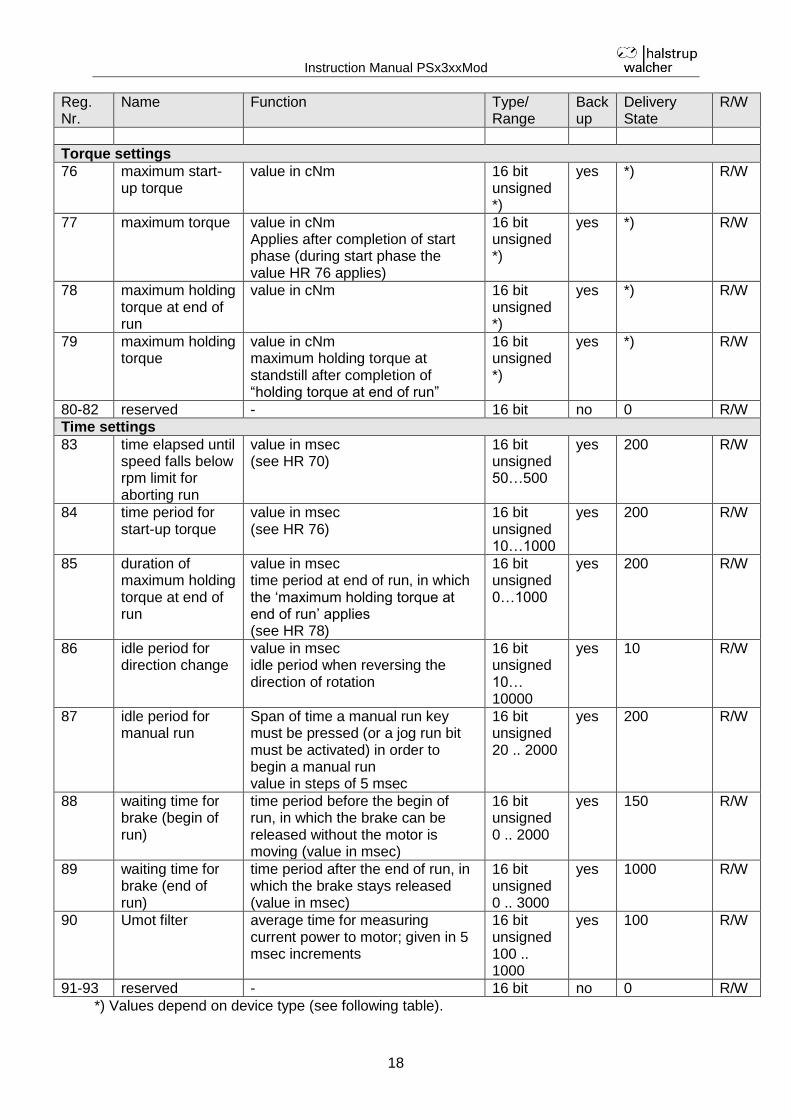
Torque settings
76 maximum start-up torque
value in cNm 16 bit unsigned *)
yes *) R/W
77 maximum torque value in cNm Applies after completion of start phase (during start phase the value HR 76 applies)
16 bit unsigned *)
yes *) R/W
78 maximum holding torque at end of run
value in cNm 16 bit unsigned *)
yes *) R/W
79 maximum holding torque
value in cNm maximum holding torque at standstill after completion of “holding torque at end of run”
16 bit unsigned *)
yes *) R/W
80-82 reserved - 16 bit no 0 R/W
Time settings
83 time elapsed until speed falls below rpm limit for aborting run
value in msec (see HR 70)
16 bit unsigned 50…500
yes 200 R/W
84 time period for start-up torque
value in msec (see HR 76)
16 bit unsigned 10…1000
yes 200 R/W
85 duration of maximum holding torque at end of run
value in msec time period at end of run, in which the ‘maximum holding torque at end of run’ applies (see HR 78)
16 bit unsigned 0…1000
yes 200 R/W
86 idle period for direction change
value in msec idle period when reversing the direction of rotation
16 bit unsigned 10… 10000
yes 10 R/W
87 idle period for manual run
Span of time a manual run key must be pressed (or a jog run bit must be activated) in order to begin a manual run value in steps of 5 msec
16 bit unsigned 20 .. 2000
yes 200 R/W
88 waiting time for brake (begin of run)
time period before the begin of run, in which the brake can be released without the motor is moving (value in msec)
16 bit unsigned 0 .. 2000
yes 150 R/W
89 waiting time for brake (end of run)
time period after the end of run, in which the brake stays released (value in msec)
16 bit unsigned 0 .. 3000
yes 1000 R/W
90 Umot filter average time for measuring current power to motor; given in 5 msec increments
16 bit unsigned 100 .. 1000
yes 100 R/W
91-93 reserved - 16 bit no 0 R/W
*) Values depend on device type (see following table).
Instruction Manual PSx3xxMod
19
Reg. Nr.
Name Function Type/ Range
Backup
Delivery State
R/W
Other settings
94-103
general purpuse 10 general purpuse registers 16 bit unsigned
yes 0 R/W
104 Umot limit voltage limit for bit ‘motor power present’ given in increments of 0.1 V
16 bit unsigned 180 .. 240
yes 185 R/W
105 temperature limit upper temperature limit in °C 16 bit unsigned 10...70
yes 70 R/W
106-115
reserved - 16 bit no 0 R/W
116 delivery state reading directly after boot: (value) = 0 content of memory correct (value) > 0 content of memory incorrect reading after saving: (value) = 0 saving finished successfully (value) AND (0xFC00) > 0 saving is still in progress (the time for saving is up to 2000 msec) (value) AND (0xFC00) = 0 AND (value) AND (0x03FF) > 0 saving is finished incorrectly writing ‘-2’: generates the delivery state (sets the device address to 1, baud rate 19200 bps, starts initial reference loop, then positioning to the middle of the measurement range) A different device address or baud rate is only active after a device reset! writing ‘-1’: generates the delivery state without modifying the device address and the baud rate (starts initial reference loop, then positioning to the middle of the measurement range) writing ‘0’: no action writing ‘1’: saves all parameters in the EEPROM A different device address or baud rate is only active after a device reset!
16 bit signed -2…3
no 0 R/W
Instruction Manual PSx3xxMod
20
Reg. Nr.
Name Function Type/ Range
Backup
Delivery State
R/W
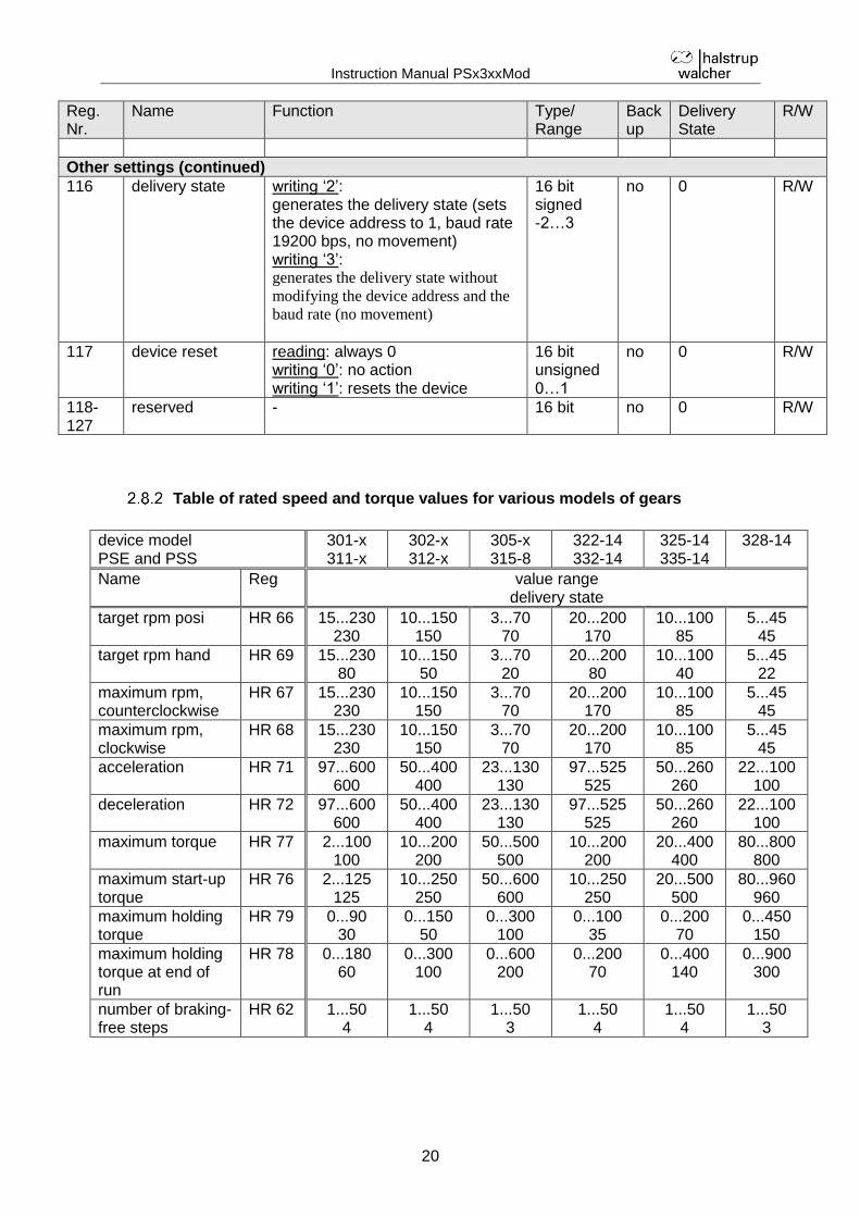
Other settings (continued)
116 delivery state writing ‘2’: generates the delivery state (sets the device address to 1, baud rate 19200 bps, no movement) writing ‘3’: generates the delivery state without
modifying the device address and the
baud rate (no movement)
16 bit signed -2…3
no 0 R/W
117 device reset reading: always 0 writing ‘0’: no action writing ‘1’: resets the device
16 bit unsigned 0…1
no 0 R/W
118-127
reserved - 16 bit no 0 R/W
Table of rated speed and torque values for various models of gears
device model PSE and PSS
301-x 311-x
302-x 312-x
305-x 315-8
322-14 332-14
325-14 335-14
328-14
Name Reg value range delivery state
target rpm posi HR 66 15...230 230
10...150 150
3...70 70
20...200 170
10...100 85
5...45 45
target rpm hand HR 69 15...230 80
10...150 50
3...70 20
20...200 80
10...100 40
5...45 22
maximum rpm, counterclockwise
HR 67 15...230 230
10...150 150
3...70 70
20...200 170
10...100 85
5...45 45
maximum rpm, clockwise
HR 68 15...230 230
10...150 150
3...70 70
20...200 170
10...100 85
5...45 45
acceleration HR 71 97...600 600
50...400 400
23...130 130
97...525 525
50...260 260
22...100 100
deceleration HR 72 97...600 600
50...400 400
23...130 130
97...525 525
50...260 260
22...100 100
maximum torque HR 77 2...100 100
10...200 200
50...500 500
10...200 200
20...400 400
80...800 800
maximum start-up torque
HR 76 2...125 125
10...250 250
50...600 600
10...250 250
20...500 500
80...960 960
maximum holding torque
HR 79 0...90 30
0...150 50
0...300 100
0...100 35
0...200 70
0...450 150
maximum holding torque at end of run
HR 78 0...180 60
0...300 100
0...600 200
0...200 70
0...400 140
0...900 300
number of braking-free steps
HR 62 1...50 4
1...50 4
1...50 3
1...50 4
1...50 4
1...50 3
Instruction Manual PSx3xxMod
21
device model PSW 301-x 311-x
302-x 312-x
305-x 315-8
322-14 332-14
325-14 335-14
328-14
Name Reg value range delivery state
target rpm posi HR 66 15...180 180
10...125 125
3...60 60
20...150 125
10...80 60
5...35 35
target rpm hand HR 69 15...180 80
10...125 50
3...60 20
20...150 80
10...80 40
5...35 22
maximum rpm, counterclockwise
HR 67 15...180 180
10...125 125
3...60 60
20...150 125
10...80 60
5...35 35
maximum rpm, clockwise
HR 68 15...180 180
10...125 125
3...60 60
20...150 125
10...80 60
5...35 35
acceleration HR 71 97...600 600
50...400 400
23...130 130
97...525 525
50...260 260
22...100 100
deceleration HR 72 97...600 600
50...400 400
23...130 130
97...525 525
50...260 260
22...100 100
maximum torque HR 77 2...100 100
10...200 200
50...500 500
10...200 200
20...400 400
80...800 800
maximum start-up torque
HR 76 2...125 125
10...250 250
50...600 600
10...250 250
20...500 500
80...960 960
maximum holding torque
HR 79 0...90 30
0...150 50
0...300 100
0...100 35
0...200 70
0...450 150
maximum holding torque at end of run
HR 78 0...180 60
0...300 100
0...600 200
0...200 70
0...400 140
0...900 300
number of braking-free steps
HR 62 1...50 4
1...50 4
1...50 3
1...50 4
1...50 4
1...50 3
device model PSE 3110-14 3125-14 3410-14 3418-14
Name Reg value range delivery state
target rpm posi HR 66 1…30 30
1…12 12
10...100 100
5...90 90
target rpm hand HR 69 1…30 12
1…12 5
10...100 40
5...90 30
maximum rpm, counterclockwise
HR 67 1…30 30
1…12 12
10...100 100
5...90 90
maximum rpm, clockwise
HR 68 1…30 30
1…12 12
10...100 100
5...90 90
acceleration HR 71 9…50 50
4…20 20
20...350 350
10...315 315
deceleration HR 72 9…50 50
4…20 20
20...350 350
10...315 315
maximum torque HR 77 100…1000 1000
250…2500 2500
100...1000 1000
100...1800 1800
maximum start-up torque
HR 76 100…1200 1200
250…3000 3000
100...1200 1200
100...2000 2000
maximum holding torque
HR 79 0…600 200
0…1250 450
0...300 200
0...450 300
maximum holding torque at end of run
HR 78 0…1200 400
0…2500 900
0...600 400
0...900 600
number of braking-free steps
HR 62 1...50 3
1...50 3
1...50 4
1...50 4
Instruction Manual PSx3xxMod
22
Detailed description of status bits
Bit 0: target position reached This bit is set:
- when a transferred target position has been reached successfully - after running an initial reference loop, when the actual value corresponds to
the previously transferred target value This bit is reset:
- after transferring a target position if the difference from the actual value is larger than the positioning window (HR 56)
- by a manual run - if an invalid target value has been transferred - if rotated manually when on standstill
Bit 1: drag error This bit is set:
- if, after the acceleration phase, the maximum speed setting has not been achieved
This bit is reset: - with each new run command
Bit 2: reverse jog key active This bit is set:
- if Pin 3 on the key connector is connected with Pin 1 (+24V) This bit is reset:
- if Pin 3 on the key connector is disconnected from Pin 1 (+24V) Bit 3: forward jog key active This bit is set:
- if Pin 2 on the key connector is connected with Pin 1 (+24V) This bit is reset:
- if Pin 2 on the key connector is disconnected from Pin 1 (+24V) Bit 4: motor power present This bit is set:
- if the supply voltage to the motor is above the Umot limit (HR 104) and below 30V
This bit is reset: - if the supply voltage to the motor is below the Umot limit or above 30V
Bit 5: positioning run aborted This bit is set:
- if a positioning run is aborted because release in the control word has been withdrawn
This bit is reset: - when a new run command is transmitted
Bit 6: drive is running This bit is set:
- when the drive is rotating This bit is reset:
- when the drive is on standstill
Instruction Manual PSx3xxMod
23
Bit 7: temperature exceeded This bit is set:
- if the internal device temperature device exceeds the limit value (HR 105) This bit is reset:
- if the internal device temperature falls below the limit value by 5°C Bit 8: movement opposite loop direction This bit is set:
- during a manual run in the direction opposite that of the loop direction (a subsequent manual run in the loop direction will not reset this bit)
- during a positioning sequence in the direction opposite that of the loop direction
This bit is reset: - when a transferred target position has been reached successfully (in the loop
direction) - after the initial reference loop
Bit 9: error This bit is set:
- if an internal problem is detected when calculating a position No run commands (except the initial reference loop) can be executed when the error bit is set!
This bit is reset: - when an initial reference loop is completed correctly
Bit 10: positioning error (block) This bit is set:
- if a positioning run is aborted because the device is overloaded (block, extreme difficulty while running)
This bit is reset: - by transmitting a new positioning command - after an initial reference loop has been executed correctly
Bit 11: manual displacement This bit is set:
- if, while on standstill, the drive is turned externally by more than the value in the positioning window
This bit is reset: - by transmitting a new positioning command - after an initial reference loop has been executed correctly
Bit 12: incorrect target value This bit is set:
- when a transferred target value lies outside of the limit switches; also caused, for instance, because of the actual value of the reference value (HR 48/49)
- when a transferred target value lies inside of the limit switches; but because of a necessary loop run the specified interval would be left
This bit is reset: - by transmitting a valid target value
Instruction Manual PSx3xxMod
24
Bit 13: motor power was missing This bit is set:
- if the power to the motor is less than the Umot limit (HR 104) or above 30V when initiating a positioning run or an initial reference loop
- if during the run the voltage leaves the given corridor This bit is reset:
- if the power to the motor is above the Umot limit and below 30V when initiating a positioning run or an initial reference loop
Bit 14 / 15: positive / negative range limit This bit is set:
- if the limit value is reached during a manual run (but not if reached during a positioning run)
- if a limit value is modified such that the current position lies beyond the limit - if, while on standstill, by means of an external force the drive is moved to a
position which is outside the area which is defined by the range limits This bit is reset:
- by initiating a positioning run, an initial reference loop or a manual run
Detailed description of control bits
Bit 0: manual run to larger values
Bit 1: manual run to smaller values
Bit 2: reserved, must be programmed to 0
Bit 3: Release for manual run in jog key mode: This bit must be set in order to
switch from jog key mode (run activated via the keys, if bit 5 is set; or via command if bit 8 or 9 is set in the control word, if bits 4 and 5 are not set) to manual run mode by holding down a key (or a jog key bit is activated for a longer time). Single increments are the only option in jog key mode if this bit is reset.
Bit 4: Release: Run commands will only be executed if this bit is set (exception is the jog key mode with the external keys or with bits 8/9 of the control word). This bit must be set for positioning runs, manual runs and must not be set for jog runs. If this bit is cleared during a run, the run will be aborted and status bit 5 will be set (‘positioning run aborted’).
Bit 5: Release for jog key mode with the external keys: If the bus is active, jog key mode via the external keys is only possible if this bit is set and bit 4 is reset. For jog key mode via the bus (bits 8 or 9 in the control word), this bit must not be set.
Bit 6: Run without loop: If this bit is set during positioning runs, all target positions will be approached directly (without loop)
Bit 7: Start initial reference loop: the device performs 5/8 of one rotation opposite to the loop direction; it will then perform 5/8 of a rotation in loop direction at manual run speed. In earlier versions, this command had to be executed after switching on the device; that is no longer the case.
Instruction Manual PSx3xxMod
25
Bit 8: reserved, must be programmed to 0
Bit 9: reserved, must be programmed to 0
Bit 10: Release readjustment: Only if this bit is set the drive readjusts when it is displaced out of its position in the direction opposite to that of the loop direction at the end of a run. If bit 6 („run without loop“) is being set, the drive readjusts the position in both directions.
Bit 11: Execute braking-free-run: At the beginning of a positioning at first the brake is released and the “waiting time for brake” is being awaited (HR 88). Within this time the brake should move towards its working position (in this position of the brake the motor can move freely). After this waiting time the motor moves a certain distance in both directions, in order to release a brake which is eventually stucked. This distance (“number of braking-free steps”) is being set in HR 62. For the execution of this command, bit 4 has to be set simultaniously
Bit 12: Run with drag error correction: If the bit is set, the drive trys (under
consideration of the configured maximum torque) to compensate a drag error which has been developped. By controling the rpm on a value which is slightly above or below the configured ‘target rpm posi’ (HR 66), the drag error decreases. The drag error correction operates only in positioning runs, i.e. not in manual runs or in jog key mode. Furthermore it operates only while accelerating and cruising with constant rpm, not while decelerating. The time-dependent setting value for the rpm while accelerating arises out of the rpm at beginning of the positioning as well as the acceleration setting (HR 71).
Bit 13: reserved, must be programmed to 0 Bit 14: reserved, must be programmed to 0 Bit 15: reserved, must be programmed to 0
Instruction Manual PSx3xxMod
26
3 Sequence of positioning
3.1 Positioning run
- Transfer target value (control word HR 32 = 0x0010h and target value HR 33/34): drive begins run
- Abort run by resetting the release bit (control word HR 32 = 0x0000h). - If a new target value is transferred during a positioning run, the device will
immediately proceed to the new target. There will be no interruption if the direction of rotation does not need to be altered.
- If a manual run is transmitted during a positioning run, the positioning run will be aborted (speed will be reduced to that of a manual run) and the device proceeds with the manual run.
The following sequence of steps is also possible: Starting situation: - release has not been set - Target value has already been transferred Set release (bit 4 in the control word HR 32): drive begins run. By default, the PSx3xx always approaches each setpoint from the same direction. If a destination is in the opposite direction to the loop direction, the setpoint is first traversed by the value of the loop length (HR 57/58) and then finally approached. This can, for example, eliminate the backlash of a driven spindle.
The PSx3xx thus distinguishes the following cases during a positioning process: Assumption: Each target position is approached in forward direction, i.e. the loop length is 250 = 5/8 rpm. 1. New setpoint position is greater than the current actual position: The target is
approached directly.
2. New setpoint position is smaller than the current actual position: The device is moved further back by the loop length (2a) and the final destination is then approached in forward motion (2b).
Instruction Manual PSx3xxMod
27
3. New setpoint position is only slightly larger than the current actual position and previously there was no positioning movement with loop (e.g. a manual movement): In all cases, the drive approaches the target with a forward movement whose length corresponds at least to the loop length. In order to achieve this, the drive first moves in reverse direction (3a), i.e. against the actually desired direction of travel, and then forwards the actual destination (3b).
The maximum length of this distance is the loop length. If the setpoint differs from the current actual value by more than the loop length, it is approached directly.
After reaching the target position, this position is compared with the internal absolute encoder status. If there is a deviation, the status bit "Error" is set (bit 9 in the status word). In the delivery state, the loop length is 250, i.e. each setpoint position is approached in the forward direction.
A positioning to the upper end limit (HR 52/53) with a loop length < 0 is not possible, since the drive would have to cross the end limit for this. The same applies to the lower end limit (HR054/55) with a loop length > 0.
3.2 Positioning run without loop
The sequence corresponds to that of a positioning run with loop; in addition to setting the release, however, bit 6 in the control word also has to be set to execute the run without loop.
3.3 Manual run
- start manual run (control word HR 32 = 0x0011h resp. 0x0012h): device begins to run - End manual run by clearing the manual run command (control word HR 32 =
0x0000h). - Transferring a target value during a manual run will end the manual run and the
device will immediately move on to the transmitted position.
Instruction Manual PSx3xxMod
28
4 Special features
4.1 Speed, acceleration and deceleration
The initial reference loop and the manual run are performed at the maximum speed specified in HR 69; positioning runs are performed at the maximum speed specified in HR 66. When the run is counterclockwise, additionally the maximum speed in HR 67 applies, when the run is clockwise, the one in HR 68 applies. For all runs the maximum acceleration in HR 71 and the maximum deceleration in HR 72 apply. At the end of each run the maximum deceleration decreases during the approach to the destination successively in order to realize a harmonic transient behaviour.
4.2 Maximum starting torque and maximum torque
Via HR 76 the maximum starting torque can be set, via HR 77 the maximum driving torque. The starting torque is active for the period in HR 84 after each start of travel. It should always be slightly higher than the driving torque, since the drive requires more torque for the acceleration phase than for constant driving. Both values are not sharp torque limits, instead the motor current is limited to a value which corresponds to the current consumption at the nominal speed at the set torque. If a lower speed than the rated speed is set, the achievable torque is slightly higher than at the (default) nominal speed.
If small torque limits are to be used, it must be considered not to use these in combination with high speed values, as this can lead to unstable driving behaviour!
4.3 Response of drive in case of block or manual displacement
If during a run due to load the speed falls below the threshold parameter of 30% (HR 70) of the selected maximum speed for longer than 200 msec (HR 83), the device detects blocking, aborts the run and sets the ‘positioning error’ bit (here the default values are given). New run commands can then be transmitted with no further steps to take. An exception is, if the run should go to the same target than before. In this case, deassert the release (bit 4 of the control word) and assert it again, then transfer the target position one more time. If the PSx3xxMod is displaced by external force during standstill opposite to the loop direction and the release bit (bit 4) as well as the release readjustment bit (bit 10) in the control word are being set, the device will attempt to reach the previously transmitted target value once again (readjustment). The device does not attempt to readjust if rotated in the loop direction; it merely sets the ‘manual rotation’ bit. If bit 6 („run without loop“) is being set, the drive readjusts the position in both directions. Deasserting the release and/or the release readjustment bit can completely stop the readjustment process.
If at standstill the drive continuously looses its position, the attempt to readjust starts exactly when the actual position is leaving the positioning window (assumed that all the conditions above are being fulfilled). If the motor power is missing at the time when this transition happens, the readjustment fails and bits10 (‘positioning error’) and 13 (‘motor power was missing’) will become active. If later the motor power comes back again, there will be no further attempt to readjust. This is to prevent a situation that suddenly a drive begins to run if motor power is being switched on.
Instruction Manual PSx3xxMod
29
4.4 Calculating the absolute physical position
The PSx3xxMod actuator includes an absolute measuring system with measurement range of 250 rotations. This allows the user to determine the direction of rotation for any desired portion of these 250 rotations. The mapping of the desired positioning range to the physical positioning range is done with the help of the parameter ‘upper mapping end’ (HR 50/51). In the delivery state, the drive is at position 51200, the upper limit switch is set to 101200 and the lower limit switch is set to 1200, yielding a positioning range of ±125 rotations (±50000 increments). So if the desired positioning range doesn’t exceed ±125 rotations, in delivery state none of the following actions to adjust the positioning range have to be taken. For the realization of any desired positioning range independent of the possible positioning range which is defined by the mounting situation (physical positioning range) there are the following two possibilities: 1) Move the axle (for example a spindle) to the desired position, then move the drive
(with opened collar) to the position value which belongs to the physical position of the axle, only then close the collar. Examples: a) Move the axle in middle position, then move the drive at no-load (with opened
collar) also to middle position (position 51200), then close the collar. The drive is now capable of moving 125 rotations (±50000 increments by default) in each direction.
b) Move the axle completely to the left (resp. bottom), then move the drive at no-load (with opened collar) without loop to the lowest position (position 1200), then close the collar. The drive is now capable of moving 250 rotations (±100000 increments by default) to the right (resp. top).
c) Move the axle completely to the right (resp. top), then move the drive at no-load (with opened collar) to the highest position (position 101200), then close the collar. The drive is now capable of moving 250 rotations (±100000 increments by default) to the left (resp. bottom).
2) Mount the drive in any position on the axle, close the collar, then adjust the positioning range with the help of HR 50/51. HR 50/51 defines the upper end of the positioning range. By default, the upper end is at +256 rotations (position 102400). If the positioning range doesn’t suit to the actual displayed position after mounting the drive, the upper end of the positioning range can be adjusted between -256 rotations and +512 rotations. Examples: a) After mounting the drive, the displayed position is 51200 (which corresponds
the delivery state). But the positioning range shall solely spread to the right (resp. top) Set HR 50/51 to 152400.
b) After mounting the drive, the displayed position is 100000. But the positioning range shall solely spread to the right (resp. top) Set HR 50/51 to 201200.
c) After mounting the drive, the displayed position is 2000. But the positioning range shall solely spread to the left (resp. bottom) Set HR 50/51 to 3200.
Remarks: 1) When calculating the upper mapping end (HR 50/51), a security reserve of 3
rotations has to be kept in mind (1200 increments by default, see the examples above), because the highest possible position value is 3 rotations below the upper mapping end. The lowest possible position value is 253 rotations below the upper mapping end.
2) The above given increment and position values relate to the following settings, which correspond to the delivery state: a) referencing value (HR 48/49) = 0
Instruction Manual PSx3xxMod
30
b) actual value assessment, numerator (HR 45) = 400 c) actual value assessment, denominator (HR 46) = 400 These 3 holding register have an influence on the above given increment and position values: With the help of the referencing value a shift can be reached, with the help of the actual value assessment numerator and denominator a stretching or distension can be reached (see below).
3) When changing the direction of rotation (HR 44), the referencing value (HR 48/49), the upper mapping end (HR 50/51) and the upper and lower limit (HR 52/53 and HR 54/55) are set to delivery state.
4) When changing the upper mapping end (HR 50/51), the upper and lower limit (HR 52/53 and HR 54/55) are set to delivery state.
5) When changing the actual value assessment numerator or denominator (HR 45 or HR 46), the target value, the actual value, the referencing value, the upper mapping end, the upper and lower limit, the positioning window and the length of loop are recalculated.
6) When changing the referencing value (HR 48/49), the target value, the actual value, the upper mapping end and the upper and lower limit are recalculated.
7) If the user wants to go over any automatic re-calculation of values when setting up the device, the optimum order of transfering the parameter is the following: a) direction of rotation (HR 44),
actual value assessment, numerator (HR 45), actual value assessment, denominator (HR 46)
b) referencing value (HR 48/49) c) upper mapping end (HR 50/51) d) upper limit (HR 52/53),
8) In order to save the settings permanently in the EEPROM, write 1 to HR 116. As soon as reading of HR 116 shows 0, the saving is finished.
Referencing value (HR 48/49): The referencing process affects all transferred values, i.e., the target value, actual value, upper mapping end and upper and lower limit. There are two ways of setting the referencing value: 1) Directly, by writing the referencing value to HR 48/49. 2) Indirectly, by writing an actual value to HR 2/3. This makes it possible to assign
any “true” actual value to the current, physical actual value. The resulting difference is then the referencing value. This value will immediately be included in calculations for each transferred value and can also be read via HR 48/49.
When changing the referencing value, automatically the target value, the actual value, the upper mapping end and the upper and lower limit are recalculated.
The removal of the motor power supply has no affect on the internal measuring system.
Instruction Manual PSx3xxMod
31
4.5 Using actual value assessment factors to set the spindle pitch
HR 45 (numerator factor) and HR 46 (denominator factor) can be used to represent any desired spindle pitch. Both factors are set to a value of 400 by default, resulting in a resolution of 0.01 mm at a spindle pitch of 4 mm. The denominator factor serves as a simple means of setting the spindle pitch and resolution. The numerator factor is primarily used for setting "unlevel" resolutions. Examples:
Spindle pitch Resolution Numerator factor
Denominator factor
4 mm 1/100 mm 400 400
1 mm 1/100 mm 400 100
2 mm 1/10 mm 400 20
Numerator and denominator factors may take on values between 1 and 10,000.
4.6 Drag error
During a positioning run, the device compares the computed target position with the current actual value. If the difference is larger than the ‘drag error’ value (HR 59), the device sets the corresponding bit in the status word. This situation is especially likely to occur if external factors (required torque, voltage to motor too low) prevent the device from achieving the target rpm.
4.7 Abort run when the master fails
If the connection to the master is interrupted during a positioning run, the master cannot abort an actual run. An automatic run abort can be generated by using HR 40. A value greater than 0 sets the time within the Master must send a new and valid request to keep the connection alive. A timout in the device will result in aborting the run.
4.8 Optional: Manual run using external keys (jog key mode)
A manual run can be performed using external keys under the following conditions: 1) when the Modbus is not connected and the address 00 is set with the help of the
address switches 2) when the Modbus is connected and in the control word bit 5 is active (‘release for
jog key mode’) and bit 4 is inactive (‘release for positioning by bus’)
The Modbus is recognized as “communicating” if there’s at least one valid telegram to the drive each second.
Instruction Manual PSx3xxMod
32
Altogether there’s the following assignment:
Modbus communicating
address control word bit 4
control word bit 5
external keys
no > 00 X X inactive
no 00 X X active
yes X X 0 inactive
yes X 1 X inactive
yes X 0 1 active
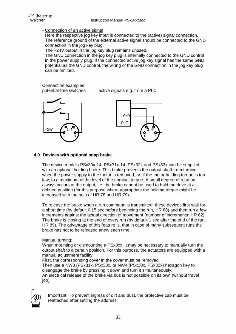
Bit 5 (‘release for jog key mode with the external keys’) and bit 4 (‘release for positioning by bus’) cannot be set simultaneously. Changing the release while running (for example from jog key mode to positioning by bus) aborts a run in the other operation mode. The operator can adjust the number of increments for a single step via HR 61. The single step is being executed if one of the external keys is being pressed. If the external key has been released before the end of the single step, it will be completed nevertheless. If the external key stays pressed further on, after a short waiting time a continuous manual run might join the single step under some circumstances. This continuous manual run will run as long as the external key stays pressed. The continuation of a single step with a manual run is always enabled if the Modbus is not active. If the Modbus is active, additionnally to bit 5 of the control word also bit 3 (‘release for manual run in jog key mode’) has to be activated. If bit 3 is not set, each pressing of the external key results in a single step, even if the key is pressed longer than the duration of the single step. The idle period before the drive switches into manual run is specified with HR 87. In manual run the drive runs maximum to the specified limit switch position (HR52/53 resp. HR 54/55). If during an jog run both external keys are pressed, the run is aborted immediately. A new jog run is only possible if both keys are released. To prepare the function of the external keys, the corresponding key contact (pin 2 or 3 of the 4-pin plug) must be connected with +24V (pin 1). If the key signal is generated by a voltage source which is galvanically separated from the internal voltage source of the drive, GND (pin 4) must be connected. Connecting the Jog Key Inputs The jog key inputs can be used in 2 different wiring modes: - Connection of potential-free switches
To activate the respective jog key input, the +24V in the jog key plug is connected here. The GND connection in the jog key plug remains unused. The 24V output in the jog key plug is internally connected to the +24V control in the supply plug. It is therefore also possible to connect the jog button inputs directly to the +24V control potential via switches.
Instruction Manual PSx3xxMod
33
- Connection of an active signal Here the respective jog key input is connected to the (active) signal connection. The reference ground of the external active signal should be connected to the GND connection in the jog key plug. The +24V output in the jog key plug remains unused. The GND connection in the jog key plug is internally connected to the GND control in the power supply plug. If the connected active jog key signal has the same GND potential as the GND control, the wiring of the GND connection in the jog key plug can be omitted.
Connection examples: potential-free switches active signals e.g. from a PLC
4.9 Devices with optional snap brake
The device models PSx30x-14, PSx31x-14, PSx32x and PSx33x can be supplied with an optional holding brake. This brake prevents the output shaft from turning when the power supply to the motor is removed, or, if the motor holding torque is too low, to a maximum of the level of the nominal torque. A small degree of rotation always occurs at the output, i.e. the brake cannot be used to hold the drive at a defined position (for this purpose where appropriate the holding torque might be increased with the help of HR 78 and HR 79). To release the brake when a run command is transmitted, these devices first wait for a short time (by default 0.15 sec before beginning the run, HR 88) and then run a few increments against the actual direction of movement (number of increments: HR 62). The brake is closing at the end of every run (by default 1 sec after the end of the run, HR 89). The advantage of this feature is, that in case of many subsequent runs the brake has not to be released anew each time. Manual turning: When mounting or dismounting a PSx3xx, it may be necessary to manually turn the output shaft to a certain position. For this purpose, the actuators are equipped with a manual adjustment facility: First, the corresponding cover in the cover must be removed. Then use a NW3 (PSx31x, PSx33x, or NW4 (PSx30x, PSx32x) hexagon key to disengage the brake by pressing it down and turn it simultaneously. An electrical release of the brake via bus is not possible on its own (without travel job).
Important! To prevent ingress of dirt and dust, the protective cap must be reattached after setting the address.
Instruction Manual PSx3xxMod
34
A "forced" turning of the drive without disengaging the brake leads to the destruction of the brake and thus of the drive!
manual adjustement under cover
PSx31x-14, PSx33x-14 PSx30x-14, PSx32x-14
4.10 Devices with optional holding brake
The device model PSE34xx can be supplied with an optional holding brake. This brake prevents the output shaft from turning when the power supply to the motor is removed, or, if the motor holding torque is too low. A run command is not approached immediately but only after a short idle period to tighten the brake. The brake releases at the end of every run. To adjust the drive manually, it is first necessary to remove the corresponding rubber-plug in the top cover (see drawings at the end of these instructions). The drive can then be rotated using a hex wrench NW4. This is quite difficult as the operator has to overcome both any torque present at the output and the force of the friction brake. The brake is not damaged by manual rotation.
manual adjustement under cover
Instruction Manual PSx3xxMod
35
4.11 Reference runs
The PSx3xxMod positioning system is equipped with an absolute measuring system, therefore there’s no need for a reference run when powering on the drive. However, if in certain cases a reference run onto a hard block should be desired (e.g. uniquely when installing the drive at a machine), the course of action should be the following: 1) Before commanding the reference run the following settings have to be carried
out: - set the maximum torque (HR 77) and the maximum start-up torque (HR 76) to
max. 10% of the nominal torque - set the maximum holding torque (HR 79) and the maximum holding torque at
end of run (HR 78) to 0 - set the rpm limit for aborting run (HR 70) to 60 - set the time elapsed until speed falls below rpm limit for aborting run (HR 83)
to 100 (The span of time in which the drive trys to get over the block, decreases: With the reduced values the positioning will be aborted if the speed stays below 60% of the target speed for longer than 100ms. By default, these values are 30% and 200ms.)
- set the corresponding upper and lower limit (HR 52/53 or HR 54/55) in a way that the block location lays considerable within the area between the upper and lower limit (Otherwise there’s the danger that the block is located within the positioning window and consequently won’t be recognized.)
- Where appropriate, reduce the target speed for manual run (HR 69). 2) Now start the reference run as manual run (set bit 0 or 1 in the control word). 3) Wait for the drive moving (bit 6 in the status word is set). 4) Wait for the drive has stopped and a positioning error has appeared (bit 6 in the
status word is cleared, bit 10 is set). 5) Start a manual run in the opposite direction with the same settings (move a
certain distance away from the hard stop in order the drive can move freely). 6) Only now adjust the desired settings of the adove mentioned holding registers for
normal operation.
4.12 Reverse drive
In vertical positioning with spherical roller spindles, pitches of approx. 4..10 mm and weights from 100 kg, it is possible that the PSx3xx does not consume any energy from the motor supply when travelling downwards, but rather generates some. This regenerative operation is permissible under certain conditions. The energy generated is fed back into the motor supply network via the internal regenerative circuit and must be drawn off there. The PSx3xx increases the voltage in the motor supply network until the additional energy is drawn off. However, the internal protection diode limits this voltage to max. 31 VDC. The following cases should be considered: 1) If several PSx3xx and/or other loads are connected to the same power supply,
regeneration is possible without any additional measures if several PSx3xx do not generate power simultaneously. The other devices then act as consumers of the energy generated by a PSx3xx.
2) If several PSx3xx are to use the regenerative circuit simultaneously, an overvoltage protection must be provided in the motor supply network.
If a PSx3xx is operated for more than 1-2 seconds in regenerative mode without consumer of the generated energy, this damages the internal protection diode and the PSx3xx is defective.
Instruction Manual PSx3xxMod
36
5 Technical Data
5.1 Ambient conditions
ambient temperature 0 °C to +45 °C
storage temperature -10 °C to +70 °C
shock resistance according to DIN IEC 68-2-27
50 g 11 msec
resistance to vibration according to DIN IEC 68-2-6
10 Hz to 55 Hz 1.5 mm 55 Hz to 1000 Hz 10 g 10 Hz to 2000 Hz 5 g
EMC standards CE
conformity CE declaration of conformity available upon request
protection class PSE IP 54
PSS IP 65
PSW IP 66 (in operation) IP 68 (at standstill)
duty cycle Device model Duty cycle in % Base time in sec.
PSE34xx PSE30xx to 33xx
PSS PSW
20 30 20 20
300 300 600 600
5.2 Electrical data
nominal power output PSx30x, PSx31x, PSE31xx
25 W with 30 % duty cycle
PSx32x, PSx33x 35 W with 30 % duty cycle
PSE34xx 100 W with 20 % duty cycle
supply voltage 24 VDC ±10 % (supply voltages for motor and control unit are galvanically isolated) advice: use regulated power supplys
positioning range 250 usable rotations, no mechanical limits measuring system has a span of 256 turns, minus 3 turns security stock at upper and lower range limit
torsional rigidity (angle of rotation when switching from operation without backlash to maximum torque)
max. 0.2°
gear backlash (without spindle compenation run)
max. 0.5°
spindle lash compensation automatic loop after every positioning run (may be deactivated)
output shaft PSE30x-8, PSE31x-8
8H9 hollow shaft with adjustable collar
PSE30x-14, PSE31x-14, PSE32x, PSE33x
14H7 hollow shaft with adjustable collar
PSE31xx-14 PSE34xx
14H7 hollow shaft with clamp and feather key
PSS3xx-8 PSW3xx-8
8H9 hollow shaft with adj. collar or
8h8 solid shaft
PSS3xx-14 PSW3xx-14
14H7 hollow shaft with adj. collar or
14h8 solid shaft
recommended diameter of the spindle head
according to the hollow shaft diameter with an interference fit of h9
maximum radial force 40 N
maximum axial force 20 N
dimensions (l x w x h) see drawings
weight (approx.) PSx30x-8 650 g
PSx30x-14, PSx32x 1200 g
PSx31x-8 700 g
PSx31x-14, PSx33x 700 g
PSE31xx 1200 g
PSE34xx 1900 g
For additional specifications and dimension drawings, please visit our website at