12
Instruction Manual Pure Sine Wave Inverter UPS (3 IN 1 Inverter)

Instruction Manual Pure Sine Wave Inverter UPS
(3 IN 1 Inverter)

Contents
1. Safety Guidelines ----------------------------------------------------------------1
2. Product Introduction------------------------------------------------------------2
2.1 Main Specification-------------------------------------------------------------------- 3
3.Panel Description-----------------------------------------------------------------4
3.1 Front Panel--------------------------------------------------------------------------4
3.2 Rear Panel---------------------------------------------------------------------------5
4.Setup (Output Voltage, Frequency, and Saving Mode)-------5
4.1 Initial State---------------------------------------------------------------------------5
5.Protection-----------------------------------------------------------------------------5
5.1 Input Protection----------------------------------------------------------------------5
5.2 Output Protection---------------------------------------------------------------------6
5.3 Failure Message Guidelines-----------------------------------------------------------7
6.Installation & Wiring-------------------------------------------------------------7
6.1 Wiring for Batteries---------------------------------------------------------------------7
6.2 Suggested Battery Bank Capacity------------------------------------------------------8
6.3 Requirement of Installation-----------------------------------------------------------8
6.4 Mounting Suggestion--------------------------------------------------------------------8
6.5 Derating----------------------------------------------------------------------------------9
7.Failure Correction Notes------------------------------------------------------ 9/10
8.Installation Diagram------------------------------------------------------10
9.Warranty--------------------------------------------------------------------------- ---10

1.Safety Guidelines (Please read through this manual before assembling the power inverter)
·Risk of electrical shock and energy hazard. All failures should be examined by the qualified technician. Please do not remove the case of the inverter by yourself.
· please do not install the inverter in places with high moisture or near water.
· please do not install the inverter in places with high ambient temperature, under direct sunlight or near flame source. · please only connect batteries with the same brand and model number in one battery bank. Using batteries from different manufacturers or different capacity is strictly prohibited. ·Never allow a spark or flame in the vicinity of the batteries because it may generate explosive gases during normal operation. · Make sure the air flow from the fan is not obstructed at both sides (front and back) of the inverter. Please allow at least 15cm of space. ·Please do not stact any object on the inverter.
WARNING: Batteries will have a aging problem after years of operation. It is suggested to execute regular battery maintenance(e.g. every year). Once aged, the batteries should be changed by professional technician, or the failed batteries may cause fire or other hazards.
①

2.Product Introduction
Inverter UPS is a combination of an inverter, battery charger and AC auto-transfer switch.
Utility Priority: when the utility is present the inverter transfer this power to the household applicances (load) and uses what excess there is to charge the battery bank with its built-in charger. When utility is disconnected, the inverter will switch back to inverting from the batteries without disrupting the power going to the appliances. This is usually very quick, less than 35ms.
Battery Priority: when inverter output is available, output as invertering is priority. When inverter output is unavailable, this unit will transfer to utility, the utility supply AC to equipments, transfer time less than 10ms.
Remarks: The design of our inverter UPS is Zero-crossing switch.
②
2.1 Main Specification

Output Waveform Pure Sine Wave (THD<3%)
Model YX-500-US YX-600-US YX-1000-US YX-1500-US YX-2000-US YX-2500-US YX-3000-US
Continuous Power 500W 600W 1000W 1500W 2000W 2500W 3000W
Peak Power 1000W 1200W 2000W 3000W 4000W 5000W 6000W
No Load Current Draws < 0.5A < 0.5A < 0.5A < 0.7A < 0.9A < 0.9A < 1.1A
Dimensions(L*W*H)mm 265x150x70 265x150x70 300x220x80 300x220x80 440x220x80 440x220x80 535x220x80
Weight 2.0 ± 0.2kgs 2.0 ± 0.2kgs 4.0 ± 0.2kgs 4.0 ± 0.2kgs 6.20 ± 0.2kgs 6.20 ± 0.2kgs 8.0 ± 0.5kgs
Max charger current12V 24V 12V 24V 12V 24V 12V 24V 12V 24V 12V 24V 12V 24V
5A 2.5A 5A 2.5A 10A 5A 10A 5A 20A 10A 20A 10A 20A 10A
Feature Automatic switching ( Zero-crossing switch)
Transfer TimeInverter converting mains supply time: <10ms
mains supply converting inverter time: <35ms
Efficiency up to 92%
Input Voltage 12V/24V/48V/72V/96V/110V
Output Voltage 100V/110V/115V/120V/220V/230V/240V
Frequency 50Hz/60Hz
Protection Function
Low voltage shutdown protection
Over input voltage protection
Over temperature protection
Over load protection
Short circuit protection
Reverse polarity protection
Fuse Internal or external
Battery type Open & Sealed Lead Acid
Application Automobiles, RVs, boats, tractors, turcks, laptops, TV sets, video games, Cdplayers, DVD players, power tool, office equipment, major household appliances, etc.
Environment
Operating temperature 0°C--+40°C @ 100% load; ≥ +60°C @ 50% load
Operating relative humidity 20%--90% RH non-condensing
Storage temperature -30°C--+70°C
Cooling Fan automatically run inner temperature is risig up ≥ 45ºC, or load power is rising up ≥20%
③
3.Panel Description
YXP-500-UPS YXP-600-UPS YXP-1000-UPS YXP-1500-UPS YXP-2000-UPS YXP-2500-UPS YXP-3000-UPS
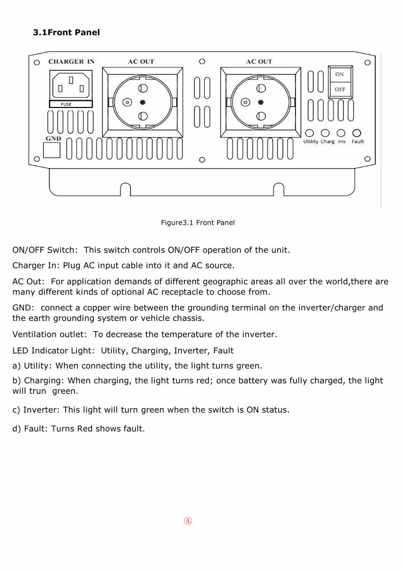
3.1Front Panel
Figure3.1 Front Panel
ON/OFF Switch: This switch controls ON/OFF operation of the unit.
Charger In: Plug AC input cable into it and AC source.
AC Out: For application demands of different geographic areas all over the world,there are many different kinds of optional AC receptacle to choose from.
GND: connect a copper wire between the grounding terminal on the inverter/charger and the earth grounding system or vehicle chassis.
Ventilation outlet: To decrease the temperature of the inverter.
LED Indicator Light: Utility, Charging, Inverter, Fault
a) Utility: When connecting the utility, the light turns green.
b) Charging: When charging, the light turns red; once battery was fully charged, the light will trun green.
c) Inverter: This light will turn green when the switch is ON status.
d) Fault: Turns Red shows fault.
④

3.2 Rear Panel
Fig 3.2: Rear Panel
Fuse: Fuse was built-out is a very good design as you can very easy to change the fuse outside the inverter if your inverter fuse was blown.
DC Battery Terminals: Connect the inverter to battery or other power source. Negative (-) and Positive(+) DC terminals should be kept insulated to protect from accidental short circuits.
Cooling fan: Temperature and load controlled.
4. Setup (Output Voltage, Frequency, and Saving Mode) 4.1 Initial State
⑴ The initial state is 230Vac/50Hz or 110Vac/60Hz
⑵ Setting standby saving mode (unused)
5. Protection 5.1 Input Protection
⑴ Battery Reversed Polarity Protection:If the battery input is connected in reverse polarity, the internal (or external) fuse of the inverter would blow and the inverter should be send back FACTORY for repair. (For the inverter with external fuse, there is the spare fuse in the box. Please disclose the fuse case of the front panel and replace it when the fuse was blew. )
(2)Battery Low Voltage Protection:When the battery voltage is lower than the preset value, the inverter will automatically shut down and the buzzer alarm will sound 3 times. Fault light turns red at the same time.
⑤

⑶ Battery Over Voltage Protection:When the battery voltage is higher than the preset value, the inverter will automatically shut down and the buzzer alarm will sound 4 times. Fault light turns red at the same time.
WARNING: Please choose suitable batteries that is compatible with the rated input DC voltage of inverter (refer to the SPEC). If the input DC voltage is too low (ex. Using 12VDC battery bank for 24VDC input models), the inverter can not be started up properly. If the input voltage is too high (ex.using 48VDC battery bank for 24VDC input models), the inverter will be damaged!
5.2 Output Protection
The display panel will show failure status when inverter is faced with abnormal operating conditions (Refer to Table 5.3). This lets the user kow what could be the problem.
⑴ Over Temperature Protection(OTP):When the inverter's internal temperature is higher than the limit value (65 degrees), the "Over Temperature Pretection" will be activated. The buzzer alarm will be sounded 5 times (continuous alarm) and the fault light turns red at the same time. When the internal temperature drops to 45 degrees, the inverte will automatically return to normal status.
⑵ AC Output Abnormal Protection:When the AC output voltage of the inverter is too high or too low , the unit will turn off and should be restarted again.
⑶ AC Output Short Circuit Protection: When a short circuit situation occurs at the output side of the inverter or the loads increase greatly in a short period of time, the unit will turn off and should be restarted again.
⑷ Battery Voltage Abnormal Protection:When the battery voltage is too high or too low, this protection will be activated. The inverter will auto recover after the battery voltage go back to a safe level and users do not need to restart it.
⑸ Output Overload Protection(OLP):When output is overloaded 120%, the inverter will automatically shut down after 5S' continuous alram, the unit will automatically restart after another 5S' waiting. (continuous loop) ; When output is overloaded 150%, the inverter will automatically shut down after 1S and the buzzer alarm will sound 2 times. (continuous loop)
⑥
5.3 Fault Messages Guidelines

Symptom Fault Messages
Buzzer alarm is sounded 1 times
The normal starting of inverter: LED light turns green, indicating that the unit is operating normally.
Buzzer alarm is sounded 2 times
Overload protection: Fault LED light blinks, indicating that the load is 150% higher than rated power.
Buzzer alarm is sounded 3 times
Low voltage protection: Fault LED light turns red , indicating that the battery voltage is too low.
Buzzer alarm is sounded 4 times
Over voltage protection: Fault LED turns red, indicating that the battery voltage is too high.
Buzzer alarm is sounded 5 times
Over temperature protection: Fault LED light turns red, indicating that the internal temperature is too high.
Buzzer alarm is sounded continuously
Overload protection: The inverter will shut down after 5S, and then restarts automatically after another 5S' waiting. (continuous loop).
6. Installation & Wiring
6.1 Wiring for Batteries:Wire connections should be as short as possible and less than 1.5 meter is highly recommended. Make sure that suitable wires are chosen based on the rating of current. Too small of a cross-section will result in overheating that could induce certain danger. Please refer to Table 6-1.
Note: Please consult our local distributors if you have any questions.
Table 6-1 Suggestion for Wire Selection
Rated Current of Equipment
(amp)
Cross-section of Lead (mm²)
AWG Suggested Wiring
16A-25A 2.5 12
Safety Wiring Range
25A-32A 4 1032A-40A 6 840A-60A 10 663A-80A 16 480A-100A 25 2100A-125A 35 1
≧125A 50 0
⑦

6.2 Suggested Battery Bank Capacity
·In according with the minimum safety starting ,full load discharge time and minimum configuration capacity, the users could choose battery bank of larger capacity (to meet the discharge time) to meet the requirement.
·Simple calculation of battery discharge time:Battery capacity / discharge current = discharge time
eg:12V/220V/50Hz/300W full load of inverter100%
Discharge time is required to be 1 hour. What is the optional battery capacity?
·Select the configuration capacity according to the following formula:
⑴ 300W÷0.89%=337W Output power/efficiency = input power
⑵ 337W÷10.5V=32A Input power / battery voltage (low voltage node) = Input Current
⑶ 32A×1hour=32AH Input current × discharge time = battery capacity
⑷40Ah battery could meet the discharge time of 85 minutes.
Note: (Actual discharge time error may exist according to the lifespan and mantainenece of the battery.)
6.3 Requirement of Installation
The unit should be mounted on a flat surface or holding rack with suitable strenth. In order to ensure the lifespan of the unit, please refrain from operating in environment of high dust, high temperature or high moisture. This is a power supply with built-in DC fan. Please make sure that ventilation is not blocked.
(Note: There should be no barriers within 15cm of the ventilating holes.)
Figure 6.3: Example of Installation
6.4 Mounting Suggestion:
There are 4 semi-circular cutout on the side flanges of the inverter. It can be used for fixing inverter onto the system enclosure.we high recommend mounting is the horizontal position. Please make sure ventilation openings are free from obstruction.
⑧

6.5 Derating
Figure 6.5.1 Output Derating Curve Figure 6.5.2 Input Derating Curve
Notes on output load:
The inverter can power most of equipments that need an AC source which can provide inverter continuously. But for certain load type, the unit may not work properly.
⑴ Since inductive loads or motor based equipments need a large start up current (6~10 times of its rated current), the inverter may not start up successfully with these kinds of load.
⑵. When the output are capacitive or rectified equipments (such as switching power supply), it is suggested to operate these equipment at no load or light load. To ensure proper operation, you should increase the load only after the inverter has started up.
7. Failure Correct Notes
The inverter should be serviced by a professional technician. Any importer usage or modification may damage the unit or result in shock hazard. If you are not able to clear the failure condition, please contact FACTORY or any our distributors for repair service.
⑨

Status Possible ReasonsWays to Eliminate
No AC output voltage
Abnormal input
Check the AC or DC input sources. Make sure the voltage is within the required range.
Over temperature protection
Make sure that the ventilation is not blocked or whether the ambient temperature is too high. Please derating the output usage or reduce the ambient temperature.
Overload protection
Make sure the output load does not exceed the rated value or the instantaneous start up current is not too high. (for inductive or capacitive loads)
Short circuit protection
Make sure the output is not overloaded or shout circuited.
Discharging period of batteries is too short.
Batteries are aged or broken
Replace the batteries
Battery capacity is too small
Reconfirm the specification and enlarge the battery capacity as suggested
Fan does not spin
Clog with foreign bodies
Remove the foreign objects
Malfunction of the fan
Repaire required. Please send it back to us or any of our distributors.
8.Installation diagram(Dimension figure)
As the models size is different, the factory will attach installation diagram with every unit (within the package box)
9.Warranty
One year of global warranty is provided for inverter under normal operating conditions. Please do not change components or modify the unit by yourself or FACTORY may reserve the right not to provide the complete warranty.
⑩


