80
Effective October 2009 Instructional Leaflet IL70C1036H06 Digitrip models 1150, 1150i, 1150+, and 1150i+ trip units for use only in Magnum and Magnum DS circuit breakers
Effective October 2009Instructional Leaflet IL70C1036H06
Digitrip models 1150, 1150i, 1150+, and1150i+ trip units for use only in Magnumand Magnum DS circuit breakers
2
Instructional Leaflet IL70C1036H06Effective October 2009
Digitrip models 1150, 1150i, 1150+, and 1150i+ trip units for use only in Magnum
and Magnum DS circuit breakers
eaton corporation www.eaton.com
contentsDescription Page Description Page
List of figures . . . . . . . . . . . . . . . . . . . . . . . . . . . . . . . . . . . . . . . . . 3List of tables . . . . . . . . . . . . . . . . . . . . . . . . . . . . . . . . . . . . . . . . . . 4Section 1: General description of Digitrip trip units . . . . . . . . . . . . 5
Protection . . . . . . . . . . . . . . . . . . . . . . . . . . . . . . . . . . . . . . . . . . . 8Mode of trip and status information . . . . . . . . . . . . . . . . . . . . . . 8Installation and removal . . . . . . . . . . . . . . . . . . . . . . . . . . . . . . . . 9Wiring . . . . . . . . . . . . . . . . . . . . . . . . . . . . . . . . . . . . . . . . . . . . 10Plexiglass cover . . . . . . . . . . . . . . . . . . . . . . . . . . . . . . . . . . . . . 10Digitrip 1150 Power/Relay Module . . . . . . . . . . . . . . . . . . . . . . 10Standards . . . . . . . . . . . . . . . . . . . . . . . . . . . . . . . . . . . . . . . . . . 10
Section 2: Description of Magnum circuit breakers . . . . . . . . . . . 11General . . . . . . . . . . . . . . . . . . . . . . . . . . . . . . . . . . . . . . . . . . . . 11Low-energy trip actuator . . . . . . . . . . . . . . . . . . . . . . . . . . . . . . 11Ground fault protection . . . . . . . . . . . . . . . . . . . . . . . . . . . . . . . 11Current sensors for standard breaker . . . . . . . . . . . . . . . . . . . . 12Current sensors for double-wide circuit breakers . . . . . . . . . . . 12
Section 3: Principles of operation . . . . . . . . . . . . . . . . . . . . . . . . 16General . . . . . . . . . . . . . . . . . . . . . . . . . . . . . . . . . . . . . . . . . . . . 16Trip and operation indicators . . . . . . . . . . . . . . . . . . . . . . . . . . . 16Making Current Release (MCR) . . . . . . . . . . . . . . . . . . . . . . . . . 16Zone interlocking . . . . . . . . . . . . . . . . . . . . . . . . . . . . . . . . . . . . 17PT module . . . . . . . . . . . . . . . . . . . . . . . . . . . . . . . . . . . . . . . . . 18
Section 4: Programming/viewing Digitrip 1150 (via front panel) . . 19MaIn menu . . . . . . . . . . . . . . . . . . . . . . . . . . . . . . . . . . . . . . . . 20Program settings PGM SET . . . . . . . . . . . . . . . . . . . . . . . . . . . . 21View settings (VIEW SET) . . . . . . . . . . . . . . . . . . . . . . . . . . . . . 27METER menu . . . . . . . . . . . . . . . . . . . . . . . . . . . . . . . . . . . . . . . 28HaRMonIC menu . . . . . . . . . . . . . . . . . . . . . . . . . . . . . . . . . . . 28Event log . . . . . . . . . . . . . . . . . . . . . . . . . . . . . . . . . . . . . . . . . . 28Power and energy parameters . . . . . . . . . . . . . . . . . . . . . . . . . 28Power quality . . . . . . . . . . . . . . . . . . . . . . . . . . . . . . . . . . . . . . . 28Waveform capture feature . . . . . . . . . . . . . . . . . . . . . . . . . . . . . 29Health (applicable only to Digitrip 1150+ Rev . E or higher) . . . . 29
Section 5: Test procedures . . . . . . . . . . . . . . . . . . . . . . . . . . . . . . 30General . . . . . . . . . . . . . . . . . . . . . . . . . . . . . . . . . . . . . . . . . . . . 30When to test . . . . . . . . . . . . . . . . . . . . . . . . . . . . . . . . . . . . . . . 30Performance testing for ground fault trip units . . . . . . . . . . . . . 30
Section 6: Battery . . . . . . . . . . . . . . . . . . . . . . . . . . . . . . . . . . . . . 32General . . . . . . . . . . . . . . . . . . . . . . . . . . . . . . . . . . . . . . . . . . . . 32Battery test . . . . . . . . . . . . . . . . . . . . . . . . . . . . . . . . . . . . . . . . 32Battery installation and removal . . . . . . . . . . . . . . . . . . . . . . . . . 32
Section 7: Frame ratings (sensor ratings and rating plugs) . . . . . . 33Section 8: Record keeping . . . . . . . . . . . . . . . . . . . . . . . . . . . . . . 34Section 9: References . . . . . . . . . . . . . . . . . . . . . . . . . . . . . . . . . . 35
Magnum and Magnum DS circuit breakers . . . . . . . . . . . . . . . . 35Time-current curves . . . . . . . . . . . . . . . . . . . . . . . . . . . . . . . . . . 35
Section 10: Digitrip 1150 with Maintenance Mode . . . . . . . . . . . 36General . . . . . . . . . . . . . . . . . . . . . . . . . . . . . . . . . . . . . . . . . . . . 36Maintenance Mode settings . . . . . . . . . . . . . . . . . . . . . . . . . . . 36arming Maintenance Mode . . . . . . . . . . . . . . . . . . . . . . . . . . . 36Remote indicator . . . . . . . . . . . . . . . . . . . . . . . . . . . . . . . . . . . . 37Choosing the reduction setting . . . . . . . . . . . . . . . . . . . . . . . . . 37Tripping and testing . . . . . . . . . . . . . . . . . . . . . . . . . . . . . . . . . . 37
appendix a: Zone interlocking examples . . . . . . . . . . . . . . . . . . . 38appendix B: Troubleshooting guide . . . . . . . . . . . . . . . . . . . . . . . . 40appendix C: Typical circuit breaker master connection diagram . . 42appendix D: Display menu diagrams . . . . . . . . . . . . . . . . . . . . . . 43appendix E: Display abbreviations . . . . . . . . . . . . . . . . . . . . . . . . 71
Glossary of terms a–K . . . . . . . . . . . . . . . . . . . . . . . . . . . . . . . . 71Glossary of terms L–Z . . . . . . . . . . . . . . . . . . . . . . . . . . . . . . . . 72
appendix F: Digitrip settings and descriptions . . . . . . . . . . . . . . . 73appendix G: auxiliary relays . . . . . . . . . . . . . . . . . . . . . . . . . . . . . 76appendix H: Digital relay accessory module . . . . . . . . . . . . . . . . . 77appendix I: Modbus translator wiring . . . . . . . . . . . . . . . . . . . . . . 78
3
Instructional Leaflet IL70C1036H06Effective October 2009
Digitrip models 1150, 1150i, 1150+, and 1150i+ trip units for use only in Magnum and Magnum DS circuit breakers
eaton corporation www.eaton.com
List of figuresDescription Page
Figure 1 . Digitrip 1150 With Rating Plug . . . . . . . . . . . . . . . . . . . . . . . . . . . . . . . . . . . . . . . . . . . . . . . . . . . . . . . . . . . . . . . . . . . . . . . . . . . . . . .5Figure 2 . Installation of the Digitrip Unit into a Magnum Circuit Breaker (Side View) . . . . . . . . . . . . . . . . . . . . . . . . . . . . . . . . . . . . . . . . . . . .9Figure 3 . Installation of the Rating Plug and Mounting Screw . . . . . . . . . . . . . . . . . . . . . . . . . . . . . . . . . . . . . . . . . . . . . . . . . . . . . . . . . . . . . .9Figure 4 . Power/Relay Module for 1150 Trip Unit . . . . . . . . . . . . . . . . . . . . . . . . . . . . . . . . . . . . . . . . . . . . . . . . . . . . . . . . . . . . . . . . . . . . . . .10Figure 5 . Tripping Circuit for a Typical Magnum Circuit Breaker (Partial) . . . . . . . . . . . . . . . . . . . . . . . . . . . . . . . . . . . . . . . . . . . . . . . . . . . . .11Figure 6 . Three-Pole, Four-Wire Circuit Breaker with neutral Sensor Connections for Standard Circuit Breaker Using Residual Ground Fault Sensing . . . . . . . . . . . . . . . . . . . . . . . . . . . . . . . . . . . . . . . . . . . . . . . . . . . . . . . . . . . . . . . . . . . . . . . . . . . . . . . .13Figure 7 . neutral Sensor Connections for Double-Wide Circuit Breaker Using Residual Ground Fault Sensing . . . . . . . . . . . . . . . . . . . . . . .13Figure 8 . Digitrip neutral Sensor Types . . . . . . . . . . . . . . . . . . . . . . . . . . . . . . . . . . . . . . . . . . . . . . . . . . . . . . . . . . . . . . . . . . . . . . . . . . . . . . .13Figure 9 . Four-Pole 3200a Standard (4000a IEC) Circuit Breaker Using Residual Ground Fault (Earth-Fault) Sensing . . . . . . . . . . . . . . . . . .14Figure 10 . Source Ground Fault Sensing Scheme for Standard Circuit Breaker . . . . . . . . . . . . . . . . . . . . . . . . . . . . . . . . . . . . . . . . . . . . . . . .14Figure 11 . Source Ground Fault Sensing Scheme for Double-Wide Circuit Breaker . . . . . . . . . . . . . . . . . . . . . . . . . . . . . . . . . . . . . . . . . . . .14Figure 12 . Zero Sequence Sensing Scheme for Standard Circuit Breaker . . . . . . . . . . . . . . . . . . . . . . . . . . . . . . . . . . . . . . . . . . . . . . . . . . . .14Figure 13 . Multiple Source/Multiple Ground Scheme . . . . . . . . . . . . . . . . . . . . . . . . . . . . . . . . . . . . . . . . . . . . . . . . . . . . . . . . . . . . . . . . . . . .15Figure 14 . PT Module with Dielectric Disconnect Plug . . . . . . . . . . . . . . . . . . . . . . . . . . . . . . . . . . . . . . . . . . . . . . . . . . . . . . . . . . . . . . . . . .16Figure 15 . Digitrip 1150 Block Diagram with Circuit Breaker Interface . . . . . . . . . . . . . . . . . . . . . . . . . . . . . . . . . . . . . . . . . . . . . . . . . . . . . .17Figure 16 . Digitrip 1150 LSI with arcflash Reduction Maintenance SystemE . . . . . . . . . . . . . . . . . . . . . . . . . . . . . . . . . . . . . . . . . . . . . . . .18Figure 17 . Digitrip 1150 LSIG with arcflash Reduction Maintenance System . . . . . . . . . . . . . . . . . . . . . . . . . . . . . . . . . . . . . . . . . . . . . . . . .18Figure 18 . Digitrip 1150i IEC . . . . . . . . . . . . . . . . . . . . . . . . . . . . . . . . . . . . . . . . . . . . . . . . . . . . . . . . . . . . . . . . . . . . . . . . . . . . . . . . . . . . . . .18Figure 19 . Digitrip 1150i IEC-EF . . . . . . . . . . . . . . . . . . . . . . . . . . . . . . . . . . . . . . . . . . . . . . . . . . . . . . . . . . . . . . . . . . . . . . . . . . . . . . . . . . . .19Figure 20 . Digitrip 1150 LSIa . . . . . . . . . . . . . . . . . . . . . . . . . . . . . . . . . . . . . . . . . . . . . . . . . . . . . . . . . . . . . . . . . . . . . . . . . . . . . . . . . . . . . .19Figure 21 . Digitrip 1150i IEC with arcflash Reduction Maintenance System . . . . . . . . . . . . . . . . . . . . . . . . . . . . . . . . . . . . . . . . . . . . . . . . . .19Figure 22 . Digitrip 1150i IEC-EF with arcflash Reduction Maintenance System . . . . . . . . . . . . . . . . . . . . . . . . . . . . . . . . . . . . . . . . . . . . . . .19Figure 23 . Long PU Settings . . . . . . . . . . . . . . . . . . . . . . . . . . . . . . . . . . . . . . . . . . . . . . . . . . . . . . . . . . . . . . . . . . . . . . . . . . . . . . . . . . . . . . .21Figure 24 . Long Delay Time Settings . . . . . . . . . . . . . . . . . . . . . . . . . . . . . . . . . . . . . . . . . . . . . . . . . . . . . . . . . . . . . . . . . . . . . . . . . . . . . . . .21Figure 25 . Short Delay Current Settings . . . . . . . . . . . . . . . . . . . . . . . . . . . . . . . . . . . . . . . . . . . . . . . . . . . . . . . . . . . . . . . . . . . . . . . . . . . . . .22Figure 26 . Short Time Settings . . . . . . . . . . . . . . . . . . . . . . . . . . . . . . . . . . . . . . . . . . . . . . . . . . . . . . . . . . . . . . . . . . . . . . . . . . . . . . . . . . . . .22Figure 27 . Instantaneous Current Settings . . . . . . . . . . . . . . . . . . . . . . . . . . . . . . . . . . . . . . . . . . . . . . . . . . . . . . . . . . . . . . . . . . . . . . . . . . . .22Figure 28 . Ground Fault Current Settings . . . . . . . . . . . . . . . . . . . . . . . . . . . . . . . . . . . . . . . . . . . . . . . . . . . . . . . . . . . . . . . . . . . . . . . . . . . . .23Figure 29 . Ground Fault Time Delay Settings . . . . . . . . . . . . . . . . . . . . . . . . . . . . . . . . . . . . . . . . . . . . . . . . . . . . . . . . . . . . . . . . . . . . . . . . . .23Figure 30 . InCoM network with Remote Master Computer BIM II . . . . . . . . . . . . . . . . . . . . . . . . . . . . . . . . . . . . . . . . . . . . . . . . . . . . . . . .26Figure 31 . TripLink Transfer . . . . . . . . . . . . . . . . . . . . . . . . . . . . . . . . . . . . . . . . . . . . . . . . . . . . . . . . . . . . . . . . . . . . . . . . . . . . . . . . . . . . . . . .27Figure 32 . auxiliary Power Module (Front and Back Views) . . . . . . . . . . . . . . . . . . . . . . . . . . . . . . . . . . . . . . . . . . . . . . . . . . . . . . . . . . . . . . .31Figure 33 . Connection Details for Conducting Single-Pole, Single-Phase Current Tests with the Circuit Breaker Removed from the Cell . .31Figure 34 . Connection Details for Conducting Single-Phase Current Tests with the Circuit Breaker Removed from the Cell . . . . . . . . . . . .31Figure 35 . alternate Connection Details Using Three Poles to Develop a Ground Fault Condition . . . . . . . . . . . . . . . . . . . . . . . . . . . . . . . . .32Figure 36 . Digitrip Battery . . . . . . . . . . . . . . . . . . . . . . . . . . . . . . . . . . . . . . . . . . . . . . . . . . . . . . . . . . . . . . . . . . . . . . . . . . . . . . . . . . . . . . . . .32Figure 37 . Typical Trip Function Record nameplate . . . . . . . . . . . . . . . . . . . . . . . . . . . . . . . . . . . . . . . . . . . . . . . . . . . . . . . . . . . . . . . . . . . . .34Figure 38 . automatic Trip operation Record . . . . . . . . . . . . . . . . . . . . . . . . . . . . . . . . . . . . . . . . . . . . . . . . . . . . . . . . . . . . . . . . . . . . . . . . . . .34Figure 39 . Typical Performance Test Record Form . . . . . . . . . . . . . . . . . . . . . . . . . . . . . . . . . . . . . . . . . . . . . . . . . . . . . . . . . . . . . . . . . . . . . .35Figure 40 . Digitrip with arcflash Reduction Maintenance System in Magnum Circuit Breaker . . . . . . . . . . . . . . . . . . . . . . . . . . . . . . . . . . . .36Figure 41 . Digitrip 1150 with arcflash Reduction Maintenance System . . . . . . . . . . . . . . . . . . . . . . . . . . . . . . . . . . . . . . . . . . . . . . . . . . . . .36Figure 42 . Maintenance Mode Wiring Digitrip 1150 with arcflash Reduction Maintenance System . . . . . . . . . . . . . . . . . . . . . . . . . . . . . . .37Figure 43 . Typical Zone Interlocking . . . . . . . . . . . . . . . . . . . . . . . . . . . . . . . . . . . . . . . . . . . . . . . . . . . . . . . . . . . . . . . . . . . . . . . . . . . . . . . . .38Figure 44 . Typical Zone Interlocking Connections with Two Main Circuit Breakers (M1, M2) and a Tie Circuit Breaker (T) . . . . . . . . . . . . . .39Figure 45 . Typical Circuit Breaker Master Connection Diagram . . . . . . . . . . . . . . . . . . . . . . . . . . . . . . . . . . . . . . . . . . . . . . . . . . . . . . . . . . . .42Figure 46 . auxiliary Relays . . . . . . . . . . . . . . . . . . . . . . . . . . . . . . . . . . . . . . . . . . . . . . . . . . . . . . . . . . . . . . . . . . . . . . . . . . . . . . . . . . . . . . . .76Figure 47 . Digital Relay accessory Module . . . . . . . . . . . . . . . . . . . . . . . . . . . . . . . . . . . . . . . . . . . . . . . . . . . . . . . . . . . . . . . . . . . . . . . . . . .77Figure 48 . Modbus Translator Wiring . . . . . . . . . . . . . . . . . . . . . . . . . . . . . . . . . . . . . . . . . . . . . . . . . . . . . . . . . . . . . . . . . . . . . . . . . . . . . . . .78
4
Instructional Leaflet IL70C1036H06Effective October 2009
Digitrip models 1150, 1150i, 1150+, and 1150i+ trip units for use only in Magnum
and Magnum DS circuit breakers
eaton corporation www.eaton.com
List of tablesDescription Page
Table 1 . Current Protection Functions for Digitrip 1150/1150i Trip Units . . . . . . . . . . . . . . . . . . . . . . . . . . . . . . . . . . . . . . . . . . . . . . . . . . . . . .6Table 2 . Metering Data for Digitrip 1150/1150i Trip Units . . . . . . . . . . . . . . . . . . . . . . . . . . . . . . . . . . . . . . . . . . . . . . . . . . . . . . . . . . . . . . . . .7Table 3 . Power Quality Data for Digitrip 1150/1150i Trip Units . . . . . . . . . . . . . . . . . . . . . . . . . . . . . . . . . . . . . . . . . . . . . . . . . . . . . . . . . . . . .7Table 4 . Voltage Protection Functions for Digitrip 1150/1150i Trip Units . . . . . . . . . . . . . . . . . . . . . . . . . . . . . . . . . . . . . . . . . . . . . . . . . . . . . .8Table 5 . Digitrip Sensing Modes . . . . . . . . . . . . . . . . . . . . . . . . . . . . . . . . . . . . . . . . . . . . . . . . . . . . . . . . . . . . . . . . . . . . . . . . . . . . . . . . . . . .11Table 6 . Examples of the Circuit Breaker and Relay a operation Versus Frequency . . . . . . . . . . . . . . . . . . . . . . . . . . . . . . . . . . . . . . . . . . .24Table 7 . Digitrip 1150 Settings . . . . . . . . . . . . . . . . . . . . . . . . . . . . . . . . . . . . . . . . . . . . . . . . . . . . . . . . . . . . . . . . . . . . . . . . . . . . . . . . . . . . .73
5
Instructional Leaflet IL70C1036H06Effective October 2009
Digitrip models 1150, 1150i, 1150+, and 1150i+ trip units for use only in Magnum and Magnum DS circuit breakers
eaton corporation www.eaton.com
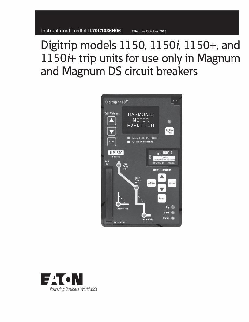
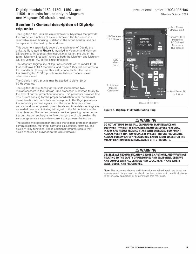
Section 1: General description of Digitrip trip unitsThe DigitripE trip units are circuit breaker subsystems that provide the protective functions of a circuit breaker . The trip unit is in a removable sealed housing, installed in the circuit breaker, and can be replaced in the field by the end user .
This document specifically covers the application of Digitrip trip units, as illustrated in Figure 1, installed in Magnum and Magnum DS breakers . Throughout this instructional leaflet, the use of the term “Magnum Breakers” refers to both the Magnum and Magnum DS low voltage, aC power circuit breakers .
The Magnum Digitrip line of trip units consists of the model 1150 that conforms to ULT standards, and model 1150i that conforms to IEC standards . Throughout this instructional leaflet, the use of the term Digitrip 1150 trip units refers to both models unless otherwise stated .
The Digitrip 1150 trip units may be applied to either 50 or 60 Hz systems .
The Digitrip DT1150 family of trip units incorporates two microprocessors in their design . one processor is devoted totally to the task of current protection functions . This processor provides true rms current sensing for the proper coordination with the thermal characteristics of conductors and equipment . The Digitrip analyzes the secondary current signals from the circuit breaker current sensors and, when preset current levels and time delay settings are exceeded, sends an initiating trip signal to the Trip actuator of the circuit breaker . The current sensors provide operating power to the trip unit . as current begins to flow through the circuit breaker, the sensors generate a secondary current that powers the trip unit .
The second microprocessor provides the voltage protection display, communications, metering, harmonic calculations, alarming, and auxiliary relay functions . These additional features require that auxiliary power be provided to the circuit breaker .
Figure 1. Digitrip 1150 With Rating Plug
m WARNINGDO NOT ATTEMPT TO INSTALL OR PERFORM MAINTENANCE ON EQUIPMENT WHILE IT IS ENERGIZED. DEATH OR SEVERE PERSONAL INJURY CAN RESULT FROM CONTACT WITH ENERGIZED EQUIPMENT. ALWAYS VERIFY THAT NO VOLTAGE IS PRESENT BEFORE PROCEEDING. ALWAYS FOLLOW SAFETY PROCEDURES. EATON IS NOT LIABLE FOR THE MISAPPLICATION OR MISINSTALLATION OF ITS PRODUCTS.
m WARNINGOBSERVE ALL RECOMMENDATIONS, NOTES, CAUTIONS, AND WARNINGS RELATING TO THE SAFETY OF PERSONNEL AND EQUIPMENT. OBSERVE AND COMPLY WITH ALL GENERAL AND LOCAL HEALTH AND SAFETY LAWS, CODES, AND PROCEDURES.
otee:N The recommendations and information contained herein are based on experience and judgement, but should not be considered to be all-inclusive or to cover every application or circumstance that may arise .
24-Character LED Display
aux . Power Module Input
Transmit LED Indicators
InCoM (red) accessory Bus (green)
Real-Time LED Indicators
Cause of Trip LED
Test Kit and TripLink
Connector
LSIG Mimic Curve
6
Instructional Leaflet IL70C1036H06Effective October 2009
Digitrip models 1150, 1150i, 1150+, and 1150i+ trip units for use only in Magnum
and Magnum DS circuit breakers
eaton corporation www.eaton.com
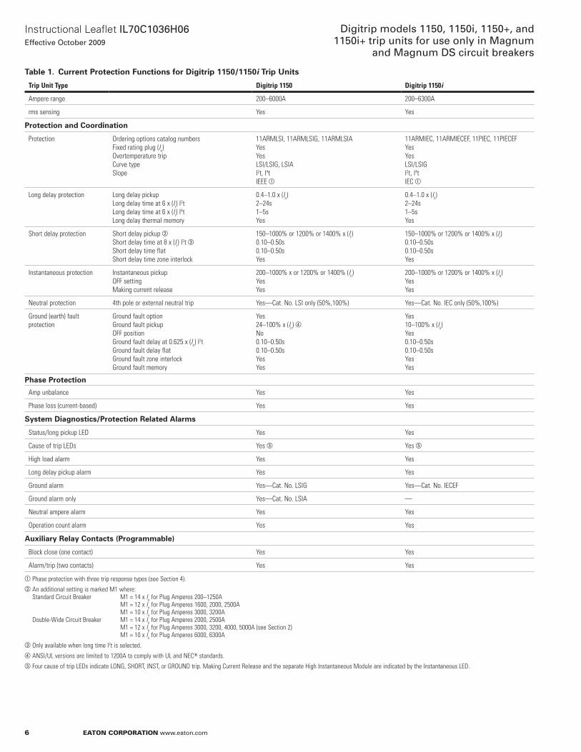
Table 1. Current Protection Functions for Digitrip 1150/1150i Trip Units
Trip Unit Type Digitrip 1150 Digitrip 1150i
Ampere range 200–6000A 200–6300A
rms sensing Yes Yes
Protection and Coordination
Protection Ordering options catalog numbersFixed rating plug (In)Overtemperature trip Curve typeSlope
11ARMLSI, 11ARMLSIG, 11ARMLSIAYesYesLSI/LSIG, LSIAI2t, I4tIEEE a
11ARMIEC, 11ARMIECEF, 11PIEC, 11PIECEFYesYesLSI/LSIGI2t, I4tIEC a
Long delay protection Long delay pickupLong delay time at 6 x (Ir) I
2tLong delay time at 6 x (Ir) I
4tLong delay thermal memory
0.4–1.0 x (In)2–24s1–5sYes
0.4–1.0 x (In)2–24s1–5sYes
Short delay protection Short delay pickup bShort delay time at 8 x (Ir) I
2t cShort delay time flatShort delay time zone interlock
150–1000% or 1200% or 1400% x (Ir)0.10–0.50s0.10–0.50sYes
150–1000% or 1200% or 1400% x (Ir)0.10–0.50s0.10–0.50sYes
Instantaneous protection Instantaneous pickupOFF settingMaking current release
200–1000% x or 1200% or 1400% (In)YesYes
200–1000% or 1200% or 1400% x (In)YesYes
Neutral protection 4th pole or external neutral trip Yes—Cat. No. LSI only (50%,100%) Yes—Cat. No. IEC only (50%,100%)
Ground (earth) fault protection
Ground fault optionGround fault pickupOFF positionGround fault delay at 0.625 x (In) I
2tGround fault delay flatGround fault zone interlockGround fault memory
Yes24–100% x (In) dNo0.10–0.50s0.10–0.50sYesYes
Yes10–100% x (In)Yes0.10–0.50s0.10–0.50sYesYes
Phase Protection
Amp unbalance Yes Yes
Phase loss (current-based) Yes Yes
System Diagnostics/Protection Related Alarms
Status/long pickup LED Yes Yes
Cause of trip LEDs Yes e Yes e
High load alarm Yes Yes
Long delay pickup alarm Yes Yes
Ground alarm Yes—Cat. No. LSIG Yes—Cat. No. IECEF
Ground alarm only Yes—Cat. No. LSIA —
Neutral ampere alarm Yes Yes
Operation count alarm Yes Yes
Auxiliary Relay Contacts (Programmable)
Block close (one contact) Yes Yes
Alarm/trip (two contacts) Yes Yes
a Phase protection with three trip response types (see Section 4).b An additional setting is marked M1 where:
Standard Circuit Breaker M1 = 14 x In for Plug Amperes 200–1250A M1 = 12 x In for Plug Amperes 1600, 2000, 2500A M1 = 10 x In for Plug Amperes 3000, 3200ADouble-Wide Circuit Breaker M1 = 14 x In for Plug Amperes 2000, 2500A M1 = 12 x In for Plug Amperes 3000, 3200, 4000, 5000A (see Section 2) M1 = 10 x In for Plug Amperes 6000, 6300A
c Only available when long time I2t is selected.d ANSI/UL versions are limited to 1200A to comply with UL and NECT standards.e Four cause of trip LEDs indicate LONG, SHORT, INST, or GROUND trip. Making Current Release and the separate High Instantaneous Module are indicated by the Instantaneous LED.
7
Instructional Leaflet IL70C1036H06Effective October 2009
Digitrip models 1150, 1150i, 1150+, and 1150i+ trip units for use only in Magnum and Magnum DS circuit breakers
eaton corporation www.eaton.com
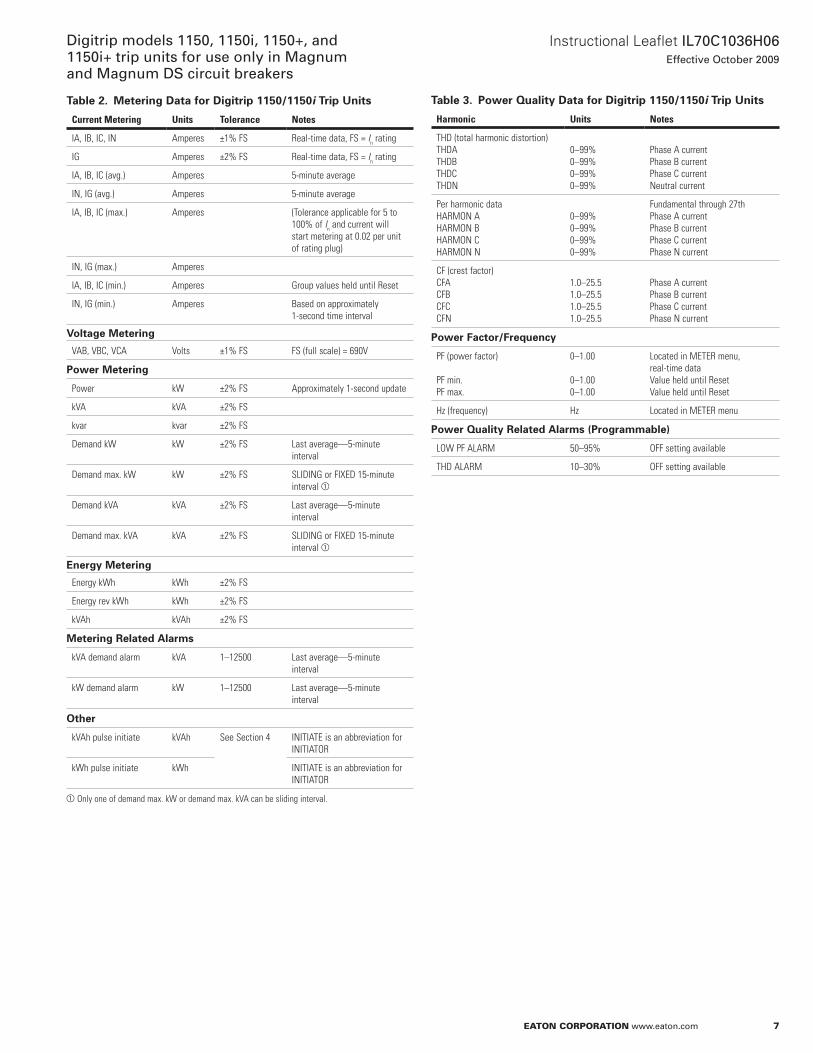
Table 2. Metering Data for Digitrip 1150/1150i Trip Units
Current Metering Units Tolerance Notes
IA, IB, IC, IN Amperes ±1% FS Real-time data, FS = In rating
IG Amperes ±2% FS Real-time data, FS = In rating
IA, IB, IC (avg.) Amperes 5-minute average
IN, IG (avg.) Amperes 5-minute average
IA, IB, IC (max.) Amperes (Tolerance applicable for 5 to 100% of In and current will start metering at 0.02 per unit of rating plug)
IN, IG (max.) Amperes
IA, IB, IC (min.) Amperes Group values held until Reset
IN, IG (min.) Amperes Based on approximately 1-second time interval
Voltage Metering
VAB, VBC, VCA Volts ±1% FS FS (full scale) = 690V
Power Metering
Power kW ±2% FS Approximately 1-second update
kVA kVA ±2% FS
kvar kvar ±2% FS
Demand kW kW ±2% FS Last average—5-minute interval
Demand max. kW kW ±2% FS SLIDING or FIxED 15-minute interval a
Demand kVA kVA ±2% FS Last average—5-minute interval
Demand max. kVA kVA ±2% FS SLIDING or FIxED 15-minute interval a
Energy Metering
Energy kWh kWh ±2% FS
Energy rev kWh kWh ±2% FS
kVAh kVAh ±2% FS
Metering Related Alarms
kVA demand alarm kVA 1–12500 Last average—5-minute interval
kW demand alarm kW 1–12500 Last average—5-minute interval
Other
kVAh pulse initiate kVAh See Section 4 INITIATE is an abbreviation for INITIATOR
kWh pulse initiate kWh INITIATE is an abbreviation for INITIATOR
a Only one of demand max. kW or demand max. kVA can be sliding interval.
Table 3. Power Quality Data for Digitrip 1150/1150i Trip Units
Harmonic Units Notes
THD (total harmonic distortion)THDATHDBTHDCTHDN
0–99%0–99%0–99%0–99%
Phase A currentPhase B currentPhase C currentNeutral current
Per harmonic dataHARMON AHARMON BHARMON CHARMON N
0–99%0–99%0–99%0–99%
Fundamental through 27thPhase A currentPhase B currentPhase C current Phase N current
CF (crest factor)CFACFBCFCCFN
1.0–25.51.0–25.51.0–25.51.0–25.5
Phase A currentPhase B currentPhase C currentPhase N current
Power Factor/Frequency
PF (power factor)
PF min.PF max.
0–1.00
0–1.000–1.00
Located in METER menu, real-time dataValue held until ResetValue held until Reset
Hz (frequency) Hz Located in METER menu
Power Quality Related Alarms (Programmable)
LOW PF ALARM 50–95% OFF setting available
THD ALARM 10–30% OFF setting available
8
Instructional Leaflet IL70C1036H06Effective October 2009
Digitrip models 1150, 1150i, 1150+, and 1150i+ trip units for use only in Magnum
and Magnum DS circuit breakers
eaton corporation www.eaton.com
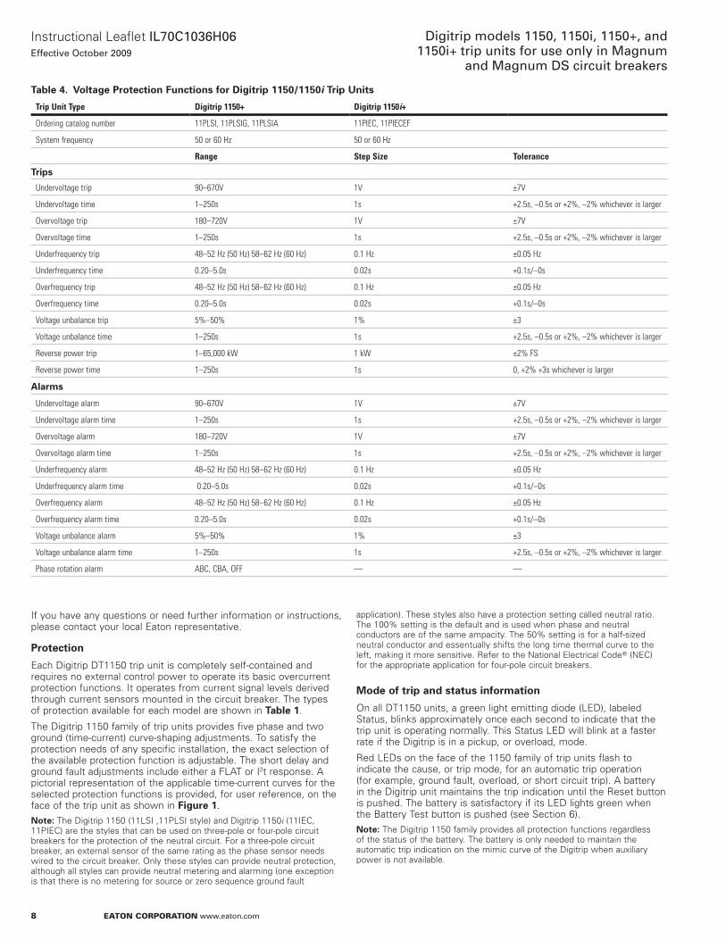
Table 4. Voltage Protection Functions for Digitrip 1150/1150i Trip Units
Trip Unit Type Digitrip 1150+ Digitrip 1150i+
Ordering catalog number 11PLSI, 11PLSIG, 11PLSIA 11PIEC, 11PIECEF
System frequency 50 or 60 Hz 50 or 60 Hz
Range Step Size Tolerance
Trips
Undervoltage trip 90–670V 1V ±7V
Undervoltage time 1–250s 1s +2.5s, –0.5s or +2%, –2% whichever is larger
Overvoltage trip 180–720V 1V ±7V
Overvoltage time 1–250s 1s +2.5s, –0.5s or +2%, –2% whichever is larger
Underfrequency trip 48–52 Hz (50 Hz) 58–62 Hz (60 Hz) 0.1 Hz ±0.05 Hz
Underfrequency time 0.20–5.0s 0.02s +0.1s/–0s
Overfrequency trip 48–52 Hz (50 Hz) 58–62 Hz (60 Hz) 0.1 Hz ±0.05 Hz
Overfrequency time 0.20–5.0s 0.02s +0.1s/–0s
Voltage unbalance trip 5%–50% 1% ±3
Voltage unbalance time 1–250s 1s +2.5s, –0.5s or +2%, –2% whichever is larger
Reverse power trip 1–65,000 kW 1 kW ±2% FS
Reverse power time 1–250s 1s 0, +2% +3s whichever is larger
Alarms
Undervoltage alarm 90–670V 1V ±7V
Undervoltage alarm time 1–250s 1s +2.5s, –0.5s or +2%, –2% whichever is larger
Overvoltage alarm 180–720V 1V ±7V
Overvoltage alarm time 1–250s 1s +2.5s, –0.5s or +2%, –2% whichever is larger
Underfrequency alarm 48–52 Hz (50 Hz) 58–62 Hz (60 Hz) 0.1 Hz ±0.05 Hz
Underfrequency alarm time 0.20–5.0s 0.02s +0.1s/–0s
Overfrequency alarm 48–52 Hz (50 Hz) 58–62 Hz (60 Hz) 0.1 Hz ±0.05 Hz
Overfrequency alarm time 0.20–5.0s 0.02s +0.1s/–0s
Voltage unbalance alarm 5%–50% 1% ±3
Voltage unbalance alarm time 1–250s 1s +2.5s, –0.5s or +2%, –2% whichever is larger
Phase rotation alarm ABC, CBA, OFF — —
If you have any questions or need further information or instructions, please contact your local Eaton representative .
Protection
Each Digitrip DT1150 trip unit is completely self-contained and requires no external control power to operate its basic overcurrent protection functions . It operates from current signal levels derived through current sensors mounted in the circuit breaker . The types of protection available for each model are shown in Table 1 .
The Digitrip 1150 family of trip units provides five phase and two ground (time-current) curve-shaping adjustments . To satisfy the protection needs of any specific installation, the exact selection of the available protection function is adjustable . The short delay and ground fault adjustments include either a FLaT or I2t response . a pictorial representation of the applicable time-current curves for the selected protection functions is provided, for user reference, on the face of the trip unit as shown in Figure 1 .
otee:N The Digitrip 1150 (11LSI ,11PLSI style) and Digitrip 1150i (11IEC, 11PIEC) are the styles that can be used on three-pole or four-pole circuit breakers for the protection of the neutral circuit . For a three-pole circuit breaker, an external sensor of the same rating as the phase sensor needs wired to the circuit breaker . only these styles can provide neutral protection, although all styles can provide neutral metering and alarming (one exception is that there is no metering for source or zero sequence ground fault
application) . These styles also have a protection setting called neutral ratio . The 100% setting is the default and is used when phase and neutral conductors are of the same ampacity . The 50% setting is for a half-sized neutral conductor and essentually shifts the long time thermal curve to the left, making it more sensitive . Refer to the national Electrical CodeT (nEC) for the appropriate application for four-pole circuit breakers .
Mode of trip and status information
on all DT1150 units, a green light emitting diode (LED), labeled Status, blinks approximately once each second to indicate that the trip unit is operating normally . This Status LED will blink at a faster rate if the Digitrip is in a pickup, or overload, mode .
Red LEDs on the face of the 1150 family of trip units flash to indicate the cause, or trip mode, for an automatic trip operation (for example, ground fault, overload, or short circuit trip) . a battery in the Digitrip unit maintains the trip indication until the Reset button is pushed . The battery is satisfactory if its LED lights green when the Battery Test button is pushed (see Section 6) .
otee:N The Digitrip 1150 family provides all protection functions regardless of the status of the battery . The battery is only needed to maintain the automatic trip indication on the mimic curve of the Digitrip when auxiliary power is not available .
9
Instructional Leaflet IL70C1036H06Effective October 2009
Digitrip models 1150, 1150i, 1150+, and 1150i+ trip units for use only in Magnum and Magnum DS circuit breakers
eaton corporation www.eaton.com
Installation and removal
Installation of the Trip Unit
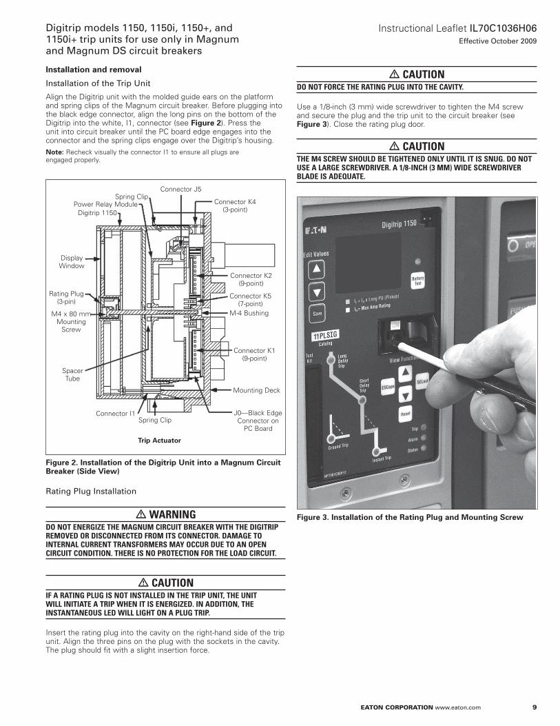
align the Digitrip unit with the molded guide ears on the platform and spring clips of the Magnum circuit breaker . Before plugging into the black edge connector, align the long pins on the bottom of the Digitrip into the white, I1, connector (see Figure 2) . Press the unit into circuit breaker until the PC board edge engages into the connector and the spring clips engage over the Digitrip’s housing .
otee:N Recheck visually the connector I1 to ensure all plugs are engaged properly .
Figure 2. Installation of the Digitrip Unit into a Magnum Circuit Breaker (Side View)
Rating Plug Installation
m WARNINGDO NOT ENERGIZE THE MAGNUM CIRCUIT BREAkER WITH THE DIGITRIP REMOVED OR DISCONNECTED FROM ITS CONNECTOR. DAMAGE TO INTERNAL CURRENT TRANSFORMERS MAY OCCUR DUE TO AN OPEN CIRCUIT CONDITION. THERE IS NO PROTECTION FOR THE LOAD CIRCUIT.
m CAUTIONIF A RATING PLUG IS NOT INSTALLED IN THE TRIP UNIT, THE UNIT WILL INITIATE A TRIP WHEN IT IS ENERGIZED. IN ADDITION, THE INSTANTANEOUS LED WILL LIGHT ON A PLUG TRIP.
Insert the rating plug into the cavity on the right-hand side of the trip unit . align the three pins on the plug with the sockets in the cavity . The plug should fit with a slight insertion force .
Spring ClipPower Relay Module
Digitrip 1150
Display Window
Rating Plug (3-pin)
M4 x 80 mm Mounting
Screw
Spacer Tube
Connector I1Spring Clip
J0—Black Edge Connector on
PC Board
Mounting Deck
Connector K1 (9-point)
M-4 Bushing
Connector K5 (7-point)
Connector K2 (9-point)
Connector K4 (3-point)
Connector J5
Trip Actuator
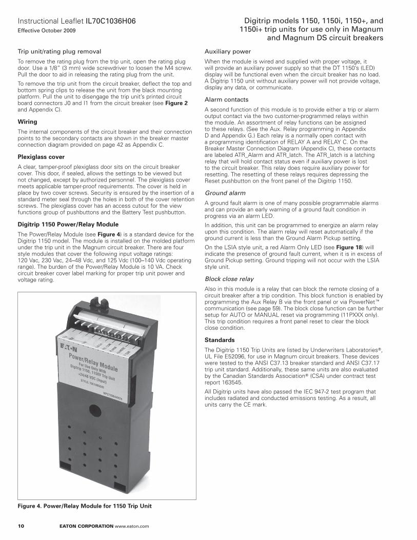
m CAUTIONDO NOT FORCE THE RATING PLUG INTO THE CAVITY.
Use a 1/8-inch (3 mm) wide screwdriver to tighten the M4 screw and secure the plug and the trip unit to the circuit breaker (see Figure 3) . Close the rating plug door .
m CAUTIONTHE M4 SCREW SHOULD BE TIGHTENED ONLY UNTIL IT IS SNUG. DO NOT USE A LARGE SCREWDRIVER. A 1/8-INCH (3 MM) WIDE SCREWDRIVER BLADE IS ADEQUATE.
Figure 3. Installation of the Rating Plug and Mounting Screw
10
Instructional Leaflet IL70C1036H06Effective October 2009
Digitrip models 1150, 1150i, 1150+, and 1150i+ trip units for use only in Magnum
and Magnum DS circuit breakers
eaton corporation www.eaton.com
Trip unit/rating plug removal
To remove the rating plug from the trip unit, open the rating plug door . Use a 1/8” (3 mm) wide screwdriver to loosen the M4 screw . Pull the door to aid in releasing the rating plug from the unit .
To remove the trip unit from the circuit breaker, deflect the top and bottom spring clips to release the unit from the black mounting platform . Pull the unit to disengage the trip unit’s printed circuit board connectors J0 and I1 from the circuit breaker (see Figure 2 and appendix C) .
Wiring
The internal components of the circuit breaker and their connection points to the secondary contacts are shown in the breaker master connection diagram provided on page 42 as appendix C .
Plexiglass cover
a clear, tamper-proof plexiglass door sits on the circuit breaker cover . This door, if sealed, allows the settings to be viewed but not changed, except by authorized personnel . The plexiglass cover meets applicable tamper-proof requirements . The cover is held in place by two cover screws . Security is ensured by the insertion of a standard meter seal through the holes in both of the cover retention screws . The plexiglass cover has an access cutout for the view functions group of pushbuttons and the Battery Test pushbutton .
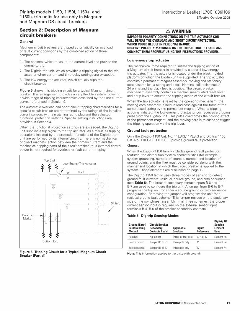
Digitrip 1150 Power/Relay Module
The Power/Relay Module (see Figure 4) is a standard device for the Digitrip 1150 model . The module is installed on the molded platform under the trip unit in the Magnum circuit breaker . There are four style modules that cover the following input voltage ratings: 120 Vac, 230 Vac, 24–48 Vdc, and 125 Vdc (100–140 Vdc operating range) . The burden of the Power/Relay Module is 10 Va . Check circuit breaker cover label marking for proper trip unit power and voltage rating .
Figure 4. Power/Relay Module for 1150 Trip Unit
Auxiliary power
When the module is wired and supplied with proper voltage, it will provide an auxiliary power supply so that the DT 1150’s (LED) display will be functional even when the circuit breaker has no load . a Digitrip 1150 unit without auxiliary power will not provide voltage, display any data, or communicate .
Alarm contacts
a second function of this module is to provide either a trip or alarm output contact via the two customer-programmed relays within the module . an assortment of relay functions can be assigned to these relays . (See the aux . Relay programming in appendix D and appendix G .) Each relay is a normally open contact with a programming identification of RELaY a and RELaY C . on the Breaker Master Connection Diagram (appendix C), these contacts are labeled aTR_alarm and aTR_latch . The aTR_latch is a latching relay that will hold contact status even if auxiliary power is lost to the circuit breaker . This relay does require auxiliary power for resetting . The resetting of these relays requires depressing the Reset pushbutton on the front panel of the Digitrip 1150 .
Ground alarm
a ground fault alarm is one of many possible programmable alarms and can provide an early warning of a ground fault condition in progress via an alarm LED .
In addition, this unit can be programmed to energize an alarm relay upon this condition . The alarm relay will reset automatically if the ground current is less than the Ground alarm Pickup setting .
on the LSIa style unit, a red alarm only LED (see Figure 18) will indicate the presence of ground fault current, when it is in excess of Ground Pickup setting . Ground tripping will not occur with the LSIa style unit .
Block close relay
also in this module is a relay that can block the remote closing of a circuit breaker after a trip condition . This block function is enabled by programming the aux Relay B via the front panel or via PowernetE communication (see page 59) . The block close function can be further setup for aUTo or ManUaL reset via programming (11Pxxx only) . This trip condition requires a front panel reset to clear the block close condition .
Standards
The Digitrip 1150 Trip Units are listed by Underwriters LaboratoriesT, UL File E52096, for use in Magnum circuit breakers . These devices were tested to the anSI C37 .13 breaker standard and anSI C37 .17 trip unit standard . additionally, these same units are also evaluated by the Canadian Standards associationT (CSa) under contract test report 163545 .
all Digitrip units have also passed the IEC 947-2 test program that includes radiated and conducted emissions testing . as a result, all units carry the CE mark .
11
Instructional Leaflet IL70C1036H06Effective October 2009
Digitrip models 1150, 1150i, 1150+, and 1150i+ trip units for use only in Magnum and Magnum DS circuit breakers
eaton corporation www.eaton.com
Section 2: Description of Magnum circuit breakersGeneral
Magnum circuit breakers are tripped automatically on overload or fault current conditions by the combined action of three components:
1. The sensors, which measure the current level and provide the energy to trip .
2. The Digitrip trip unit, which provides a tripping signal to the trip actuator when current and time delay settings are exceeded .
3. The low-energy trip actuator, which actually trips the circuit breaker .
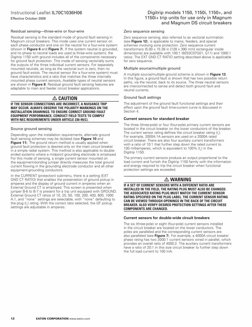
Figure 5 shows this tripping circuit for a typical Magnum circuit breaker . This arrangement provides a very flexible system, covering a wide range of tripping characteristics described by the time-current curves referenced in Section 9 .
The automatic overload and short circuit tripping characteristics for a specific circuit breaker are determined by the ratings of the installed current sensors with a matching rating plug and the selected functional protection settings . Specific setting instructions are provided in Section 4 .
When the functional protection settings are exceeded, the Digitrip unit supplies a trip signal to the trip actuator . as a result, all tripping operations initiated by the protection functions of the Digitrip trip unit are performed by its internal circuitry . There is no mechanical or direct magnetic action between the primary current and the mechanical tripping parts of the circuit breaker, thus external control power is not required for overload or fault current tripping .
Figure 5. Tripping Circuit for a Typical Magnum Circuit Breaker (Partial)
Top EndLow Energy Trip actuator
Digitrip
Polarity Marks
Bottom End
Black
m WARNINGIMPROPER POLARITY CONNECTIONS ON THE TRIP ACTUATOR COIL WILL DEFEAT THE OVERLOAD AND SHORT CIRCUIT PROTECTION, WHICH COULD RESULT IN PERSONAL INJURY. OBSERVE POLARITY MARkINGS ON THE TRIP ACTUATOR LEADS AND CONNECT THEM PROPERLY USING THE INSTRUCTIONS PROVIDED.
Low-energy trip actuator
The mechanical force required to initiate the tripping action of a Magnum circuit breaker is provided by a special low-energy trip actuator . The trip actuator is located under the black molded platform on which the Digitrip unit is supported . The trip actuator contains a permanent magnet assembly, moving and stationary core assemblies, a spring and a coil . nominal coil resistance is 24 ohms and the black lead is positive . The circuit breaker mechanism assembly contains a mechanism-actuated reset lever and a trip lever to actuate the tripping action of the circuit breaker .
When the trip actuator is reset by the operating mechanism, the moving core assembly is held in readiness against the force of the compressed spring by the permanent magnet . When a tripping action is initiated, the low-energy trip actuator coil receives a tripping pulse from the Digitrip unit . This pulse overcomes the holding effect of the permanent magnet, and the moving core is released to trigger the tripping operation via the trip lever .
Ground fault protection
only the Digitrip 1150 Cat . no . 11LSIG,11PLSIG and Digitrip 1150i Cat . no . 11IEC-EF, 11PIECEF provide ground fault protection .
General
When the Digitrip 1150 family includes ground fault protection features, the distribution system characteristics (for example, system grounding, number of sources, number and location of ground points, and the like) must be considered along with the manner and location in which the circuit breaker is applied to the system . These elements are discussed on page 12 .
The Digitrip 1150 family uses three modes of sensing to detect ground fault currents: residual, source ground, and zero sequence (see Table 5) . The breaker secondary contact inputs B-6 and B-7 are used to configure the trip unit . a jumper from B-6 to B-7 programs the trip unit for either a source ground or zero sequence configuration . Removing the jumper will program the unit for a residual ground fault scheme . This jumper resides on the stationary side of the switchgear assembly . In all three schemes, the proper current sensor input is required on the external sensor input terminals B-4, B-5 of the breaker secondary contacts .
Table 5. Digitrip Sensing Modes
Ground (Earth) Fault Sensing Method
Circuit Breaker Secondary Contacts Req’d.
Applicable Breakers
Figure Reference
Digitrip GF Sensing Element Used
Residual No jumper Three- or four-pole 6, 7, 9, 13 Element R5
Source ground Jumper B6 to B7 Three-pole only 11 Element R4
Zero sequence Jumper B6 to B7 Three-pole only 12 Element R4
otee:N This information applies to trip units with ground .
12
Instructional Leaflet IL70C1036H06Effective October 2009
Digitrip models 1150, 1150i, 1150+, and 1150i+ trip units for use only in Magnum
and Magnum DS circuit breakers
eaton corporation www.eaton.com
Residual sensing—three-wire or four-wire
Residual sensing is the standard mode of ground fault sensing in Magnum circuit breakers . This mode uses one current sensor on each phase conductor and one on the neutral for a four-wire system (shown in Figure 6 and Figure 7) . If the system neutral is grounded, and no phase to neutral loads are used (a three-wire system), the Digitrip 1150 with ground includes all of the components necessary for ground fault protection . This mode of sensing vectorially sums the outputs of the three individual current sensors . For separately mounted neutrals, as long as the vectorial sum is zero, then no ground fault exists . The neutral sensor (for a four-wire system) must have characteristics and a ratio that matches the three internally mounted phase current sensors . available types of neutral sensors are shown in Figure 8 . Residual ground fault sensing features are adaptable to main and feeder circuit breaker applications .
m CAUTIONIF THE SENSOR CONNECTIONS ARE INCORRECT, A NUISANCE TRIP MAY OCCUR. ALWAYS OBSERVE THE POLARITY MARkINGS ON THE INSTALLATION DRAWINGS. TO ENSURE CORRECT GROUND FAULT EQUIPMENT PERFORMANCE, CONDUCT FIELD TESTS TO COMPLY WITH NEC REQUIREMENTS UNDER ARTICLE 230-95(C).
Source ground sensing
Depending upon the installation requirements, alternate ground fault sensing schemes may be dictated (see Figure 10 and Figure 11) . The ground return method is usually applied when ground fault protection is desired only on the main circuit breaker in a simple radial system . This method is also applicable to double-ended systems where a midpoint grounding electrode is employed . For this mode of sensing, a single current sensor mounted on the equipment-bonding jumper directly measures the total ground current flowing in the grounding electrode conductor and all other equipment-grounding conductors .
In the CURREnT (protection) submenu, there is a setting (ExT GnD CT RaTIo) that enables the presentation of ground pickup in amperes and the display of ground current in amperes when an External Ground CT is employed . This screen is presented when jumper B-6 to B-7 is present for a trip unit equipped with GRoUnD . External Ground CT ratios of 10, 25, 50, 100, 200, 400, 800, 1000 a:1, and “none” settings are selectable, with “none” defaulting to the plug (In) rating . With the correct ratio selected, the GF pickup settings are adjustable in amperes .
Zero sequence sensing
Zero sequence sensing, also referred to as vectorial summation (see Figure 12), is applicable to mains, feeders, and special schemes involving zone protection . Zero sequence current transformers (5 .00 x 15 .38 in [128 x 390 mm] rectangular inside dimensions) are available with 100:1 (9253C07G01, G11) and 1000:1 ratios . The ExT GnD CT RaTIo setting described above is applicable for zero sequence .
Multiple source/multiple ground
a multiple source/multiple ground scheme is shown in Figure 13 . In this figure, a ground fault is shown that has two possible return paths, via the neutral, back to its source . The three neutral sensors are interconnected to sense and detect both ground fault and neutral currents .
Ground fault settings
The adjustment of the ground fault functional settings and their effect upon the ground fault time-current curve is discussed in Section 4 .
Current sensors for standard breaker
The three (three-pole) or four (four-pole) primary current sensors are located in the circuit breaker on the lower conductors of the breaker . The current sensor rating defines the circuit breaker rating (In) . For example, 2000a:1a sensors are used on a 2000a rated circuit breaker . There are also four auxiliary current transformers with a ratio of 10:1 that further step down the rated current to 100 milliamperes, which is equivalent to 100% (In) in the Digitrip 1150 .
The primary current sensors produce an output proportional to the load current and furnish the Digitrip 1150 family with the information and energy required to trip the circuit breaker when functional protection settings are exceeded .
m WARNINGIF A SET OF CURRENT SENSORS WITH A DIFFERENT RATIO ARE INSTALLED IN THE FIELD, THE RATING PLUG MUST ALSO BE CHANGED. THE ASSOCIATED RATING PLUG MUST MATCH THE CURRENT SENSOR RATING SPECIFIED ON THE PLUG LABEL. THE CURRENT SENSOR RATING CAN BE VIEWED THROUGH OPENINGS IN THE BACk OF THE CIRCUIT BREAkER. ALSO VERIFY DESIRED PROTECTION SETTINGS AFTER THESE COMPONENTS ARE CHANGED.
Current sensors for double-wide circuit breakers
The six (three-pole) or eight (four-pole) current sensors installed in the circuit breaker are located on the lower conductors . The poles are paralleled and the corresponding current sensors are also paralleled (see Figure 7) . For example, a 4000a circuit breaker phase rating has two 2000:1 current sensors wired in parallel, which provides an overall ratio of 4000:2 . The auxiliary current transformers have a ratio of 20:1 in this size circuit breaker to further step down the full load current to 100 ma .
13
Instructional Leaflet IL70C1036H06Effective October 2009
Digitrip models 1150, 1150i, 1150+, and 1150i+ trip units for use only in Magnum and Magnum DS circuit breakers
eaton corporation www.eaton.com
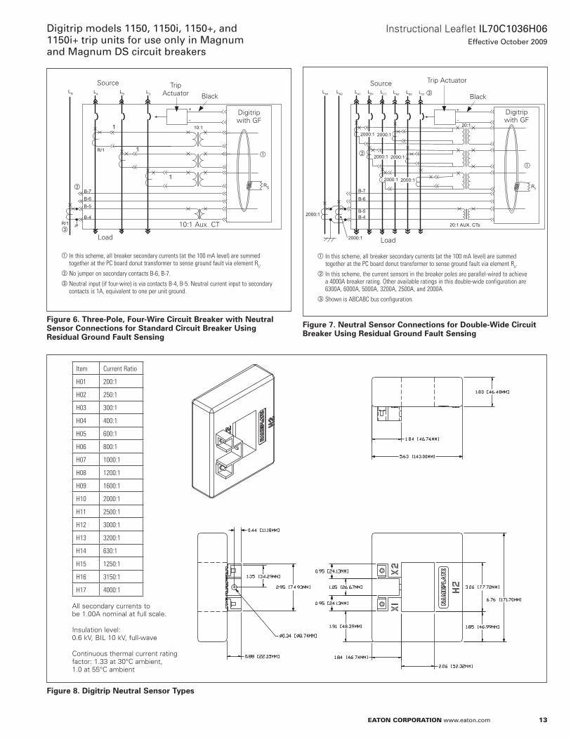
Figure 6. Three-Pole, Four-Wire Circuit Breaker with Neutral Sensor Connections for Standard Circuit Breaker Using Residual Ground Fault Sensing
LN
R5
R/1
R/1
B-4
B-6
10:1
B-5
B-7
+
-
LB LCLA
1
1
1
Source
Black
Trip actuator
Digitrip with GF
10:1 aux . CT
Load
a
b
c
a In this scheme, all breaker secondary currents (at the 100 mA level) are summed together at the PC board donut transformer to sense ground fault via element R5.
b No jumper on secondary contacts B-6, B-7.c Neutral input (if four-wire) is via contacts B-4, B-5. Neutral current input to secondary
contacts is 1A, equivalent to one per unit ground.
Figure 7. Neutral Sensor Connections for Double-Wide Circuit Breaker Using Residual Ground Fault Sensing
B-4
B-6
20:1 AUX. CTs
20:1
B-5
B-7
+
-
LA2LB1 LB2LC1LA1LN1 LN2 LC2
2000:1
2000:1
2000:1
2000:1
2000:1
2000:1
2000:1
2000:1
R5
Source
Black
Trip actuator
Digitrip with GF
Load
a
b
c
a In this scheme, all breaker secondary currents (at the 100 mA level) are summed together at the PC board donut transformer to sense ground fault via element R5.
b In this scheme, the current sensors in the breaker poles are parallel-wired to achieve a 4000A breaker rating. Other available ratings in this double-wide configuration are 6300A, 6000A, 5000A, 3200A, 2500A, and 2000A.
c Shown is ABCABC bus configuration.
Figure 8. Digitrip Neutral Sensor Types
Item Current Ratio
H01 200:1
H02 250:1
H03 300:1
H04 400:1
H05 600:1
H06 800:1
H07 1000:1
H08 1200:1
H09 1600:1
H10 2000:1
H11 2500:1
H12 3000:1
H13 3200:1
H14 630:1
H15 1250:1
H16 3150:1
H17 4000:1 all secondary currents to be 1 .00a nominal at full scale . Insulation level: 0 .6 kV, BIL 10 kV, full-wave Continuous thermal current rating factor: 1 .33 at 30°C ambient, 1 .0 at 55°C ambient
14
Instructional Leaflet IL70C1036H06Effective October 2009
Digitrip models 1150, 1150i, 1150+, and 1150i+ trip units for use only in Magnum
and Magnum DS circuit breakers
eaton corporation www.eaton.com
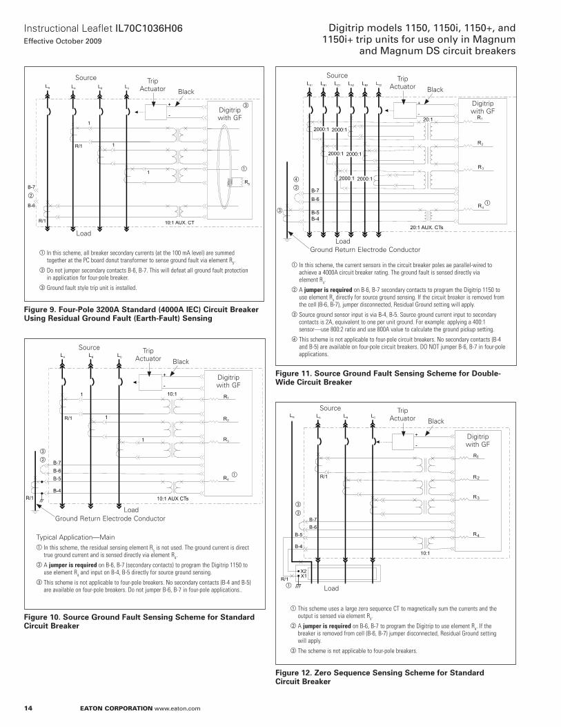
Figure 9. Four-Pole 3200A Standard (4000A IEC) Circuit Breaker Using Residual Ground Fault (Earth-Fault) Sensing
Figure 10. Source Ground Fault Sensing Scheme for Standard Circuit Breaker
5
Source
Black
Trip actuator
Digitrip with GF
Load
a
b
c
a In this scheme, all breaker secondary currents (at the 100 mA level) are summed together at the PC board donut transformer to sense ground fault via element R5.
b Do not jumper secondary contacts B-6, B-7. This will defeat all ground fault protection in application for four-pole breaker.
c Ground fault style trip unit is installed.
1
2
3
4
Source
Black
Trip actuator
Digitrip with GF
Load
a
b
c
Typical application—Maina In this scheme, the residual sensing element R5 is not used. The ground current is direct
true ground current and is sensed directly via element R4.b A jumper is required on B-6, B-7 (secondary contacts) to program the Digitrip 1150 to
use element R4 and input on B-4, B-5 directly for source ground sensing.c This scheme is not applicable to four-pole breakers. No secondary contacts (B-4 and B-5)
are available on four-pole breakers. Do not jumper B-6, B-7 in four-pole applications..
Ground Return Electrode Conductor
Figure 11. Source Ground Fault Sensing Scheme for Double-Wide Circuit Breaker
Figure 12. Zero Sequence Sensing Scheme for Standard Circuit Breaker
1
2
3
4
Source
Black
Trip actuator
Digitrip with GF
Load
a
b
d
a In this scheme, the current sensors in the circuit breaker poles ae parallel-wired to achieve a 4000A circuit breaker rating. The ground fault is sensed directly via element R4.
b A jumper is required on B-6, B-7 secondary contacts to program the Digitrip 1150 to use element R4 directly for source ground sensing. If the circuit breaker is removed from the cell (B-6, B-7), jumper disconnected, Residual Ground setting will apply.
c Source ground sensor input is via B-4, B-5. Source ground current input to secondary contacts is 2A, equivalent to one per unit ground. For example: applying a 400:1 sensor—use 800:2 ratio and use 800A value to calculate the ground pickup setting.
d This scheme is not applicable to four-pole circuit breakers. No secondary contacts (B-4 and B-5) are available on four-pole circuit breakers. DO NOT jumper B-6, B-7 in four-pole applications.
Ground Return Electrode Conductor
c
1
2
3
4
Source
Black
Trip actuator
Digitrip with GF
Loada
b
c
a This scheme uses a large zero sequence CT to magnetically sum the currents and the output is sensed via element R4.
b A jumper is required on B-6, B-7 to program the Digitrip to use element R4. If the breaker is removed from cell (B-6, B-7) jumper disconnected, Residual Ground setting will apply.
c The scheme is not applicable to four-pole breakers.
15
Instructional Leaflet IL70C1036H06Effective October 2009
Digitrip models 1150, 1150i, 1150+, and 1150i+ trip units for use only in Magnum and Magnum DS circuit breakers
eaton corporation www.eaton.com
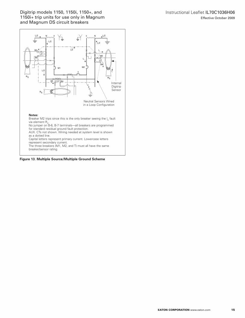
Figure 13. Multiple Source/Multiple Ground Scheme
R5 R5
R5
φ φ
T
M2M1
B5 B4
I /2G
I /2G I /2G
I /2G
IG
IG
ig
ig
i /2g
i /2G
i /2g
i /2g
i /2g
B5
B5B4
B4
N N
Internal Digitrip Sensor
otese:N Breaker M2 trips since this is the only breaker seeing the lG fault via element R5 .no jumper on B-6, B-7 terminals—all breakers are programmed for standard residual ground fault protection . aUx . CTs not shown . Wiring needed at system level is shown as a dotted line . Capital letters represent primary current . Lowercase letters represent secondary current . The three breakers (M1, M2, and T) must all have the same breaker/sensor rating .
neutral Sensors Wired in a Loop Configuration
16
Instructional Leaflet IL70C1036H06Effective October 2009
Digitrip models 1150, 1150i, 1150+, and 1150i+ trip units for use only in Magnum
and Magnum DS circuit breakers
eaton corporation www.eaton.com
Section 3: principles of operation General
The Digitrip 1150 family of trip units is designed for industrial circuit breaker environments where the ambient temperatures can range from –20°C to +85°C, but rarely exceed 70°C to 75°C . If, however, ambient temperatures exceed this range, the trip unit performance may be degraded . In order to ensure that the tripping function is not compromised due to an overtemperature condition, the Digitrip 1150 microcomputer chips have a built-in overtemperature protection feature, factory set to trip the circuit breaker if the chip temperature is excessive . If the unit trips on overtemperature, the red Long Delay Time LED will flash and the oVER TEMP TRIP message will appear on the display .
The Digitrip uses the Eaton custom-designed CHip™, an integrated circuit that includes a microcomputer to perform its numeric and logic functions . The principles of operation of the trip unit are shown in Figure 15 .
all sensing and tripping power required to operate the protection function is derived from the current sensor secondary currents whenever the circuit breaker is carrying current . These current signals develop analog voltages across the current viewing resistors . The resulting analog voltages are digitized by the CHip .
The microcomputer continually digitizes these signals . This data is used to calculate true rms current values, which are then continually compared with the protection function settings and other operating data stored in the memory . The embedded software then determines whether to initiate protection functions, including tripping the circuit breaker through the trip actuator (Ta) .
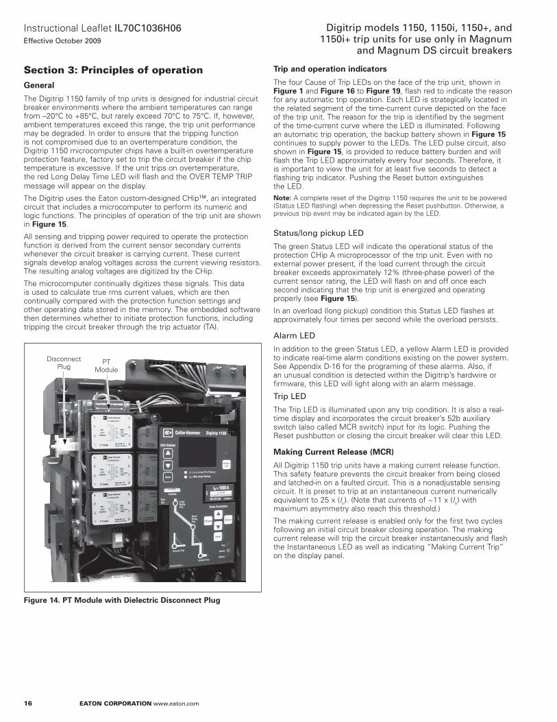
Figure 14. PT Module with Dielectric Disconnect Plug
Disconnect Plug
PT Module
Trip and operation indicators
The four Cause of Trip LEDs on the face of the trip unit, shown in Figure 1 and Figure 16 to Figure 19, flash red to indicate the reason for any automatic trip operation . Each LED is strategically located in the related segment of the time-current curve depicted on the face of the trip unit . The reason for the trip is identified by the segment of the time-current curve where the LED is illuminated . Following an automatic trip operation, the backup battery shown in Figure 15 continues to supply power to the LEDs . The LED pulse circuit, also shown in Figure 15, is provided to reduce battery burden and will flash the Trip LED approximately every four seconds . Therefore, it is important to view the unit for at least five seconds to detect a flashing trip indicator . Pushing the Reset button extinguishes the LED .
otee:N a complete reset of the Digitrip 1150 requires the unit to be powered (Status LED flashing) when depressing the Reset pushbutton . otherwise, a previous trip event may be indicated again by the LED .
Status/long pickup LED
The green Status LED will indicate the operational status of the protection CHip a microprocessor of the trip unit . Even with no external power present, if the load current through the circuit breaker exceeds approximately 12% (three-phase power) of the current sensor rating, the LED will flash on and off once each second indicating that the trip unit is energized and operating properly (see Figure 15) .
In an overload (long pickup) condition this Status LED flashes at approximately four times per second while the overload persists .
Alarm LED
In addition to the green Status LED, a yellow alarm LED is provided to indicate real-time alarm conditions existing on the power system . See appendix D-16 for the programing of these alarms . also, if an unusual condition is detected within the Digitrip’s hardwire or firmware, this LED will light along with an alarm message .
Trip LED
The Trip LED is illuminated upon any trip condition . It is also a real-time display and incorporates the circuit breaker’s 52b auxiliary switch (also called MCR switch) input for its logic . Pushing the Reset pushbutton or closing the circuit breaker will clear this LED .
Making Current Release (MCR)
all Digitrip 1150 trip units have a making current release function . This safety feature prevents the circuit breaker from being closed and latched-in on a faulted circuit . This is a nonadjustable sensing circuit . It is preset to trip at an instantaneous current numerically equivalent to 25 x (In) . (note that currents of ~11 x (In) with maximum asymmetry also reach this threshold .)
The making current release is enabled only for the first two cycles following an initial circuit breaker closing operation . The making current release will trip the circuit breaker instantaneously and flash the Instantaneous LED as well as indicating “Making Current Trip” on the display panel .
17
Instructional Leaflet IL70C1036H06Effective October 2009
Digitrip models 1150, 1150i, 1150+, and 1150i+ trip units for use only in Magnum and Magnum DS circuit breakers
eaton corporation www.eaton.com
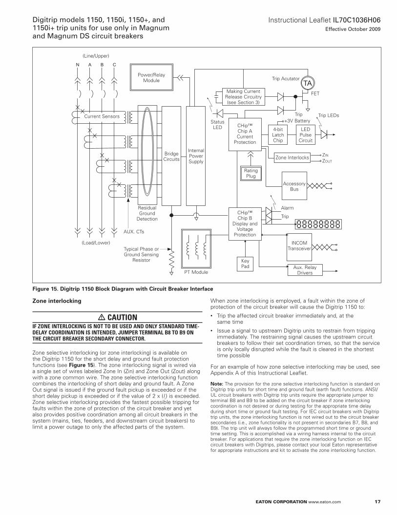
Figure 15. Digitrip 1150 Block Diagram with Circuit Breaker Interface
N A B C
TA
(Line/Upper)
Power/Relay Module
Making Current Release Circuitry (see Section 3)
Trip acutator
FET
Trip LEDsTrip+3V Battery
LED Pulse Circuit
4-bit Latch Chip
Zone Interlocks Zin
Zout
accessory Bus
Rating Plug
alarm
Trip
InCoM Transceiver
aux . Relay Drivers
Key Pad
CHip™ Chip B
Display and Voltage
Protection
PT Module
CHip™ Chip a Current
Protection
Status LED
Internal Power Supply
Bridge Circuits
Residual Ground
Detection
Typical Phase or Ground Sensing
Resistor
(Load/Lower)
aUx . CTs
Current Sensors
Zone interlocking
m CAUTIONIF ZONE INTERLOCkING IS NOT TO BE USED AND ONLY STANDARD TIME-DELAY COORDINATION IS INTENDED, JUMPER TERMINAL B8 TO B9 ON THE CIRCUIT BREAkER SECONDARY CONNECTOR.
Zone selective interlocking (or zone interlocking) is available on the Digitrip 1150 for the short delay and ground fault protection functions (see Figure 15) . The zone interlocking signal is wired via a single set of wires labeled Zone In (Zin) and Zone out (Zout) along with a zone common wire . The zone selective interlocking function combines the interlocking of short delay and ground fault . a Zone out signal is issued if the ground fault pickup is exceeded or if the short delay pickup is exceeded or if the value of 2 x (Ir) is exceeded . Zone selective interlocking provides the fastest possible tripping for faults within the zone of protection of the circuit breaker and yet also provides positive coordination among all circuit breakers in the system (mains, ties, feeders, and downstream circuit breakers) to limit a power outage to only the affected parts of the system .
When zone interlocking is employed, a fault within the zone of protection of the circuit breaker will cause the Digitrip 1150 to:• Trip the affected circuit breaker immediately and, at the
same time• Issue a signal to upstream Digitrip units to restrain from tripping
immediately . The restraining signal causes the upstream circuit breakers to follow their set coordination times, so that the service is only locally disrupted while the fault is cleared in the shortest time possible
For an example of how zone selective interlocking may be used, see appendix a of this Instructional Leaflet .
otee:N The provision for the zone selective interlocking function is standard on Digitrip trip units for short time and ground fault (earth fault) functions . anSI/UL circuit breakers with Digitrip trip units require the appropriate jumper to terminal B8 and B9 to be added on the circuit breaker if zone interlocking coordination is not desired or during testing for the appropriate time delay during short time or ground fault testing . For IEC circuit breakers with Digitrip trip units, the zone interlocking function is not wired out to the circuit breaker secondaries (i .e ., zone functionality is not present in secondaries B7, B8, and B9) . The trip unit will always follow the programmed short time or ground time setting . This is accomplished via a wiring harness internal to the circuit breaker . For applications that require the zone interlocking function on IEC circuit breakers with Digitrips, please contact your local Eaton representative for appropriate instructions and kit to activate the zone interlocking function .
18
Instructional Leaflet IL70C1036H06Effective October 2009
Digitrip models 1150, 1150i, 1150+, and 1150i+ trip units for use only in Magnum
and Magnum DS circuit breakers
eaton corporation www.eaton.com
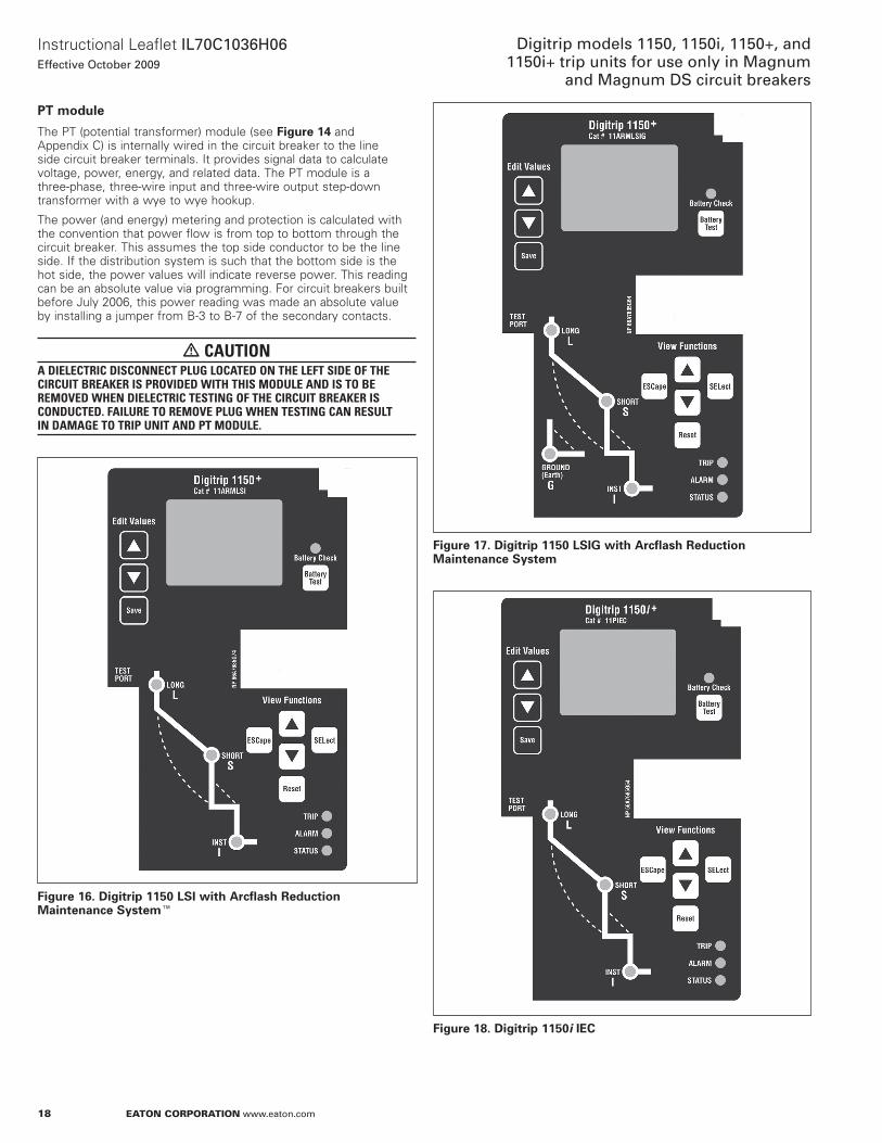
PT module
The PT (potential transformer) module (see Figure 14 and appendix C) is internally wired in the circuit breaker to the line side circuit breaker terminals . It provides signal data to calculate voltage, power, energy, and related data . The PT module is a three-phase, three-wire input and three-wire output step-down transformer with a wye to wye hookup .
The power (and energy) metering and protection is calculated with the convention that power flow is from top to bottom through the circuit breaker . This assumes the top side conductor to be the line side . If the distribution system is such that the bottom side is the hot side, the power values will indicate reverse power . This reading can be an absolute value via programming . For circuit breakers built before July 2006, this power reading was made an absolute value by installing a jumper from B-3 to B-7 of the secondary contacts .
m CAUTIONA DIELECTRIC DISCONNECT PLUG LOCATED ON THE LEFT SIDE OF THE CIRCUIT BREAkER IS PROVIDED WITH THIS MODULE AND IS TO BE REMOVED WHEN DIELECTRIC TESTING OF THE CIRCUIT BREAkER IS CONDUCTED. FAILURE TO REMOVE PLUG WHEN TESTING CAN RESULT IN DAMAGE TO TRIP UNIT AND PT MODULE.
Figure 16. Digitrip 1150 LSI with Arcflash Reduction Maintenance SystemE
Figure 17. Digitrip 1150 LSIG with Arcflash Reduction Maintenance System
Figure 18. Digitrip 1150i IEC
19
Instructional Leaflet IL70C1036H06Effective October 2009
Digitrip models 1150, 1150i, 1150+, and 1150i+ trip units for use only in Magnum and Magnum DS circuit breakers
eaton corporation www.eaton.com
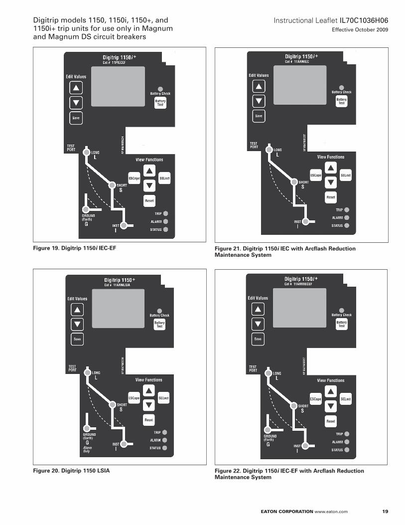
Figure 21. Digitrip 1150i IEC with Arcflash Reduction Maintenance System
Figure 22. Digitrip 1150i IEC-EF with Arcflash Reduction Maintenance System
Figure 19. Digitrip 1150i IEC-EF
Figure 20. Digitrip 1150 LSIA
20
Instructional Leaflet IL70C1036H06Effective October 2009
Digitrip models 1150, 1150i, 1150+, and 1150i+ trip units for use only in Magnum
and Magnum DS circuit breakers
eaton corporation www.eaton.com
Section 4: programming/viewing Digitrip 1150 (via front panel)MAIN menu
Power-up sequence
When the Digitrip 1150/1150i unit is first powered-up, two different display messages are possible . If the Digitrip has been previously commissioned with customer-made settings, the display will alternate between “Customer Settings in Use” and “Eaton-Electrical DT 1150” messages . Following this, the display will enter into the MaIn menu (see page 43) .
If Digitrip settings have not been saved previously, the trip unit is using the factory default values . on power-up, the Digitrip will then display “CHanGE FaCToRY SETUP?” . This message will stay on the screen until the user presses ESCape or the SELect pushbutton, or until an alarm or trip condition is detected .
The ESCape pushbutton action will keep the factory settings and then will enter the MaIn menu . The factory settings are listed in page 70 and are not valid for most applications . The appropriate settings need to be defined by a qualified application engineer to provide best overall protection and coordination for the power system .
a SELect pushbutton action will provide direct entry into PRoGRaM SETTInG menu . The first item presented is the Current CURVE type . LSIG or IEEE or (IEC) current curve types are possible selections depending on trip unit style . Pressing SELect again will select the curve presented in the window center and then step into the individual elements that need programmed . The VIEW up and down arrow selects the function while the EDIT up and down arrow changes value . after they are set, they need to be saved by depressing the Save pushbutton . The saving will place the customer settings in use . Verify the new settings . See page 57 for program curve, page 64 for saving, and page 48 for VIEW SETTInG menu .
Pushbutton definition
View functions
The “View Functions” group of pushbuttons is located in the lower right-hand side of the unit and includes the View Up (up arrow), View Down (down arrow), ESCape, SELect, and Reset buttons .
View Up / View Down—View Up and View Down allow the user to scroll through any available menu or submenu in the Digitrip 1150 display .
SELect—The SELect pushbutton selects the submenu for the blinking selection located in the middle of the display .
ESCape—The ESCape pushbutton brings the user up to the previous menu in the display . Multiple ESC pushbutton operation will display MaIn menu screen .
Reset—The Reset pushbutton will reset LEDs and screen data (see Reset Sequence) .
Edit values
The “Edit Values” group located in the upper left-hand corner of the Digitrip 1150 unit consists of three pushbuttons: Edit Up (indicated by an up arrow), Edit Down (down arrow), and Save . The Edit Values pushbuttons are covered by a plexiglass cover that can be sealed .
Edit Up / Edit Down—Edit Up and Edit Down allow the user to scroll up or down, respectively, through available setting values while in any PRoGRaM SETTInGS submenu . In the TEST menu, these buttons will raise or lower the test level when performing a self test .
Save—The Save pushbutton allows the user to save a group of selected programmable settings from any submenu in the PGM SET menu . Save is also used in the TEST menu . When prompted, pressing Save will begin the selected test .
Battery Test—The Battery Test pushbutton is located on the right side of the Digitrip 1150 unit, just above the rating plug door . Battery Test will light the green LED located above the pushbutton to ensure proper voltage in the battery .
Blink mode
Middle blinking—The middle display, if blinking, indicates that the menu item is selectable or that a submenu exists when a selection brings up another menu with middle text blinking .
Programming/viewing screens
The view functions control screen viewing, while edit functions apply to programming and storing settings . ALWAYS VERIFY PROGRAMMED SETTINGS BY ENTERING VIEW SETTINGS AFTER SAVING. all screens are viewable depending on the programmed settings and/or Digitrip 1150 model . In particular, the METER submenu may be programmed to include anywhere from one to 22 viewable screens when METER is selected, based on the settings chosen in the PGM SET\DISPLaY screens . Similarly, certain screens are only viewable based on availability . For example, in the PGM SET\auxRLY menu, the selected relay determines the programmable groups displayed . See appendix D .
Depending on the Digitrip 1150 model, certain menus or screens are not viewable or programmable . When using the LSI factory style unit, viewing and programming menu screens involving Ground or Earth settings are not accessible . When using the LSIG factory style unit, viewing and programming screens involving neutral Protection are not displayed .
Reset pushbutton operation (after trip)
Trip events
a Reset pushbutton operation does the following after a trip:
1. Clears the cause of trip flashing LEDs (four) after a trip event
2. Clears the Trip LED
3. Clears Display data
otee:N after a Trip event: 1 . observe any Trip LED flashing on mimic curve . 2 . observe message on LED display . 3 . Push View Down pushbutton to observe timestamp of event and view down to observe trip current data . This data, along with timestamp, will also be stored in event log . The maximum trip current value that can be displayed is 65535a . 4 . after any trip condition, the trip unit should be reset by pressing the Reset pushbutton (see Section 4 on pending alarm events) . 5 . Reclose circuit breaker as desired .
See page 47 for possible trip events and screen data displayed after a trip by using the View Down (down arrow) pushbutton .
Alarm events
alarms are tracked in real-time and a Reset pushbutton may momentarily clear the alarm but the alarm LED and alarm message will reappear if condition is still present .
The ESCape pushbutton activation will remove the alarm message from the display and return to normal menu viewing mode, but the yellow alarm LED will remain lit, as the alarm is in the system (see page 67) .
otee:N a way to clear an alarm if desired, after reviewing the alarm and its associated data, is to enter the PGM SET menu followed by the aLaRM submenu . The user can then revise or turn off the associated alarm set point value .
See page 47 for possible alarm events and page 67 for multiple alarm conditions .
21
Instructional Leaflet IL70C1036H06Effective October 2009
Digitrip models 1150, 1150i, 1150+, and 1150i+ trip units for use only in Magnum and Magnum DS circuit breakers
eaton corporation www.eaton.com
Data resets in meter screen
a Reset pushbutton operation will reset data values or group of values if the Reset pushbutton is depressed when screen value is displayed (see page 44 METER menu) .
Program settings PGM SET
Current curve type selection and pickup/time settings
General
Before placing any circuit breaker in operation, set each trip unit protection setting to the values specified by the engineer responsible for the installation . Each setting is programmed using the front panel pushbuttons and Save when the desired settings are selected . a few settings are interdependent (the LonG PU (Ir) rating will indirectly affect the SHoRT PU value) . Therefore, always verify these settings after programming by entering VIEW SETTINGS menu.
The installed rating plug must match the current sensors that establish the maximum continuous current rating of the circuit breaker (In) . Instantaneous and ground current settings are defined in multiples of (In) .
To illustrate the effect of each protection setting, simulated time-current curves are pictured on the face of the trip unit . Should an automatic trip occur (as a result of the current exceeding the pre-selected value), the LED in the appropriate segment of the simulated time-current curve will flash red, indicating the reason for the trip .
all Digitrip 1150 and Digitrip 1150i offer the LSI(G) curve as the standard factory default . The five-segment straight line curve of LonG PU and Time, SHoRT PU and Time, and InSTantaneous PU are depicted on the nameplate of the product . The GRoUnD (EaRTH) element is shown also on styles with ground fault protection . The LSIa style has ground alarm only function (see page 56 andpage 57) .
a second curve selection is also possible for UL/anSI styles . an IEEE curve that accurately follows the Inverse-Time characteristic equations can be selected (IEEE draft PC37 .112-11/95) . Curve shapes of MoDerately InVerse, VERY InVerse or ExTremely InVerse are available under PHaSE SLoPE . Each of these curve shapes have a PICKUP and TimeDIaL selection to position the curve . The short delay function is included as part of IEEE curve .
For the Digitrip 1150i, a second curve type is also possible for the international styles . an IEC curve type that accurately follows the IEC255 curve equations can be selected . The curve shapes of IEC-a (normal inverse), IEC-B (very inverse), and IEC-C (extremely inverse) are available under PHaSE SLoPE . Each of these curve shapes have a PICKUP and TimeDIaL selection to position the curve . The short delay function is included as part of IEC curve .
The available settings, for the LSIG standard curve along with the effects of changing the settings, are described below and in Figure 23 through Figure 30 . Sample settings are represented in boxes (e .g . )
LONG SLOPE setting
There is a I2t or I4t curve shape selection possible for LonG SLoPE .
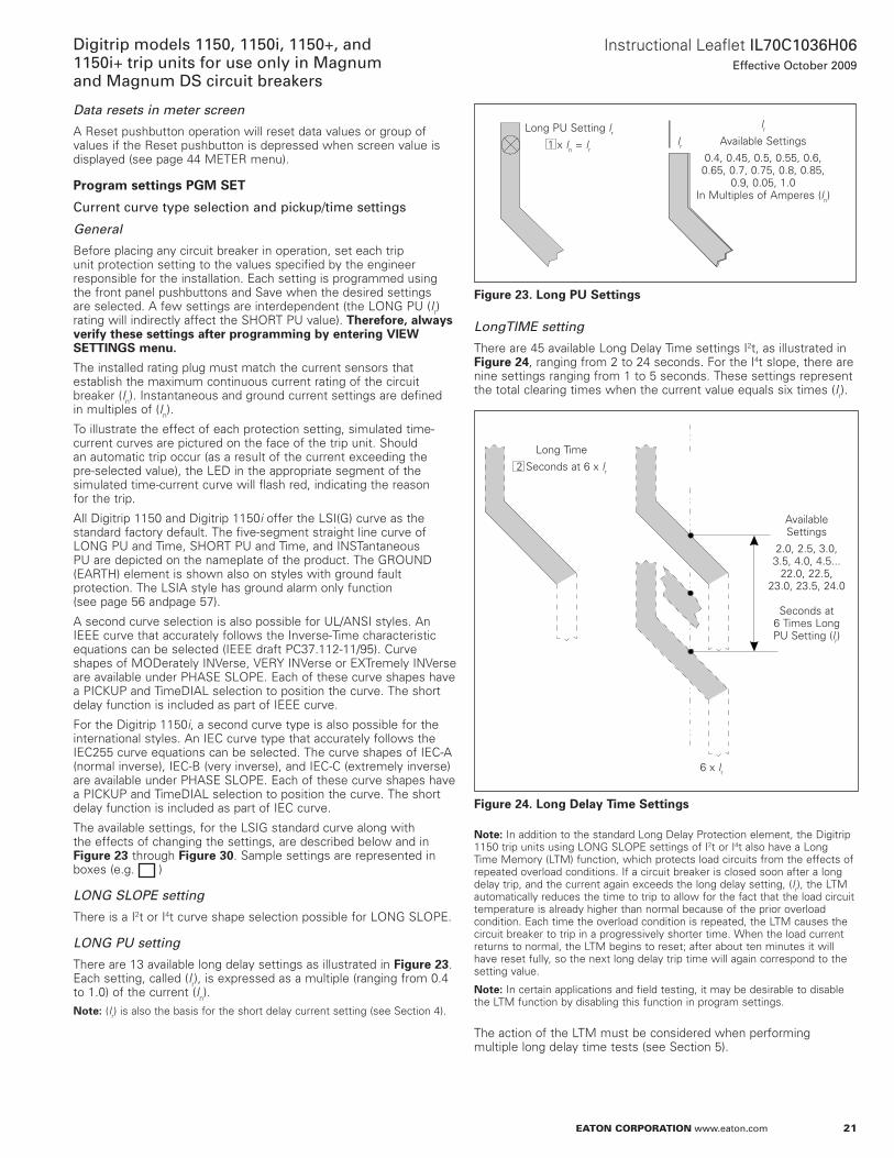
LONG PU setting
There are 13 available long delay settings as illustrated in Figure 23 . Each setting, called (Ir), is expressed as a multiple (ranging from 0 .4 to 1 .0) of the current (In) .
otee:N (Ir) is also the basis for the short delay current setting (see Section 4) .
Figure 23. Long PU Settings
LongTIME setting
There are 45 available Long Delay Time settings I2t, as illustrated in Figure 24, ranging from 2 to 24 seconds . For the I4t slope, there are nine settings ranging from 1 to 5 seconds . These settings represent the total clearing times when the current value equals six times (Ir) .
Figure 24. Long Delay Time Settings
otee:N In addition to the standard Long Delay Protection element, the Digitrip 1150 trip units using LonG SLoPE settings of I2t or I4t also have a Long Time Memory (LTM) function, which protects load circuits from the effects of repeated overload conditions . If a circuit breaker is closed soon after a long delay trip, and the current again exceeds the long delay setting, (Ir), the LTM automatically reduces the time to trip to allow for the fact that the load circuit temperature is already higher than normal because of the prior overload condition . Each time the overload condition is repeated, the LTM causes the circuit breaker to trip in a progressively shorter time . When the load current returns to normal, the LTM begins to reset; after about ten minutes it will have reset fully, so the next long delay trip time will again correspond to the setting value .
otee:N In certain applications and field testing, it may be desirable to disable the LTM function by disabling this function in program settings .
The action of the LTM must be considered when performing multiple long delay time tests (see Section 5) .
Long PU Setting lr
1 x ln = lr
lr
available Settings
0 .4, 0 .45, 0 .5, 0 .55, 0 .6, 0 .65, 0 .7, 0 .75, 0 .8, 0 .85,
0 .9, 0 .05, 1 .0 In Multiples of amperes (ln)
lr
Long Time
2 Seconds at 6 x lr
available Settings
2 .0, 2 .5, 3 .0, 3 .5, 4 .0, 4 .5 . . .
22 .0, 22 .5, 23 .0, 23 .5, 24 .0
Seconds at
6 Times Long PU Setting (lr)
6 x lr
22
Instructional Leaflet IL70C1036H06Effective October 2009
Digitrip models 1150, 1150i, 1150+, and 1150i+ trip units for use only in Magnum
and Magnum DS circuit breakers
eaton corporation www.eaton.com
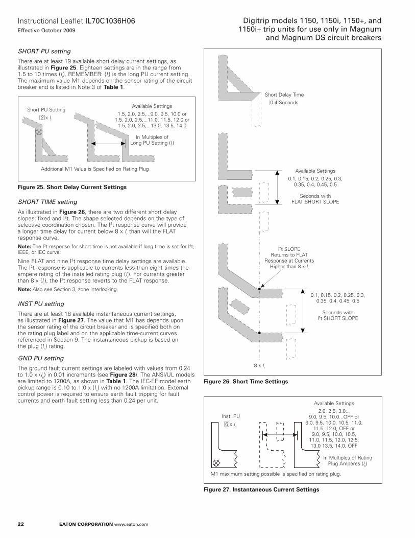
SHORT PU setting
There are at least 19 available short delay current settings, as illustrated in Figure 25 . Eighteen settings are in the range from 1 .5 to 10 times (Ir) . REMEMBER: (Ir) is the long PU current setting . The maximum value M1 depends on the sensor rating of the circuit breaker and is listed in note 3 of Table 1 .
Figure 25. Short Delay Current Settings
SHORT TIME setting
as illustrated in Figure 26, there are two different short delay slopes: fixed and I2t . The shape selected depends on the type of selective coordination chosen . The I2t response curve will provide a longer time delay for current below 8 x Ir than will the FLaT response curve .
otee:N The I2t response for short time is not available if long time is set for I4t, IEEE, or IEC curve .
nine FLaT and nine I2t response time delay settings are available . The I2t response is applicable to currents less than eight times the ampere rating of the installed rating plug (Ir) . For currents greater than 8 x (Ir), the I2t response reverts to the FLaT response .
otee:N also see Section 3, zone interlocking .
INST PU setting
There are at least 18 available instantaneous current settings, as illustrated in Figure 27 . The value that M1 has depends upon the sensor rating of the circuit breaker and is specified both on the rating plug label and on the applicable time-current curves referenced in Section 9 . The instantaneous pickup is based on the plug (In) rating .
GND PU setting
The ground fault current settings are labeled with values from 0 .24 to 1 .0 x (In) in 0 .01 increments (see Figure 28) . The anSI/UL models are limited to 1200a, as shown in Table 1 . The IEC-EF model earth pickup range is 0 .10 to 1 .0 x (In) with no 1200a limitation . External control power is required to ensure earth fault tripping for fault currents and earth fault setting less than 0 .24 per unit .
Short PU Setting
2 x lr
available Settings
1 .5, 2 .0, 2 .5, . . .9 .0, 9 .5, 10 .0 or 1 .5, 2 .0, 2 .5, . . .11 .0, 11 .5, 12 .0 or
1 .5, 2 .0, 2 .5, . . .13 .0, 13 .5, 14 .0
In Multiples of Long PU Setting (lr)
additional M1 Value is Specified on Rating Plug
Figure 26. Short Time Settings
Figure 27. Instantaneous Current Settings
Short Delay Time
0 .4 Seconds
available Settings
0 .1, 0 .15, 0 .2, 0 .25, 0 .3, 0 .35, 0 .4, 0 .45, 0 .5
Seconds with
FLaT SHoRT SLoPE
l2t SLoPEReturns to FLaT
Response at Currents Higher than 8 x lr
0 .1, 0 .15, 0 .2, 0 .25, 0 .3, 0 .35, 0 .4, 0 .45, 0 .5
Seconds with
l2t SHoRT SLoPE
8 x lr
Inst . PU
6 x ln
available Settings
2 .0, 2 .5, 3 .0 . . . 9 .0, 9 .5, 10 .0 . . .oFF or
9 .0, 9 .5, 10 .0, 10 .5, 11 .0, 11 .5, 12 .0, oFF or 9 .0, 9 .5, 10 .0, 10 .5,
11 .0, 11 .5, 12 .0, 12 .5, 13 .0 13 .5, 14 .0, oFF
M1 maximum setting possible is specified on rating plug .
In Multiples of Rating Plug amperes (ln)
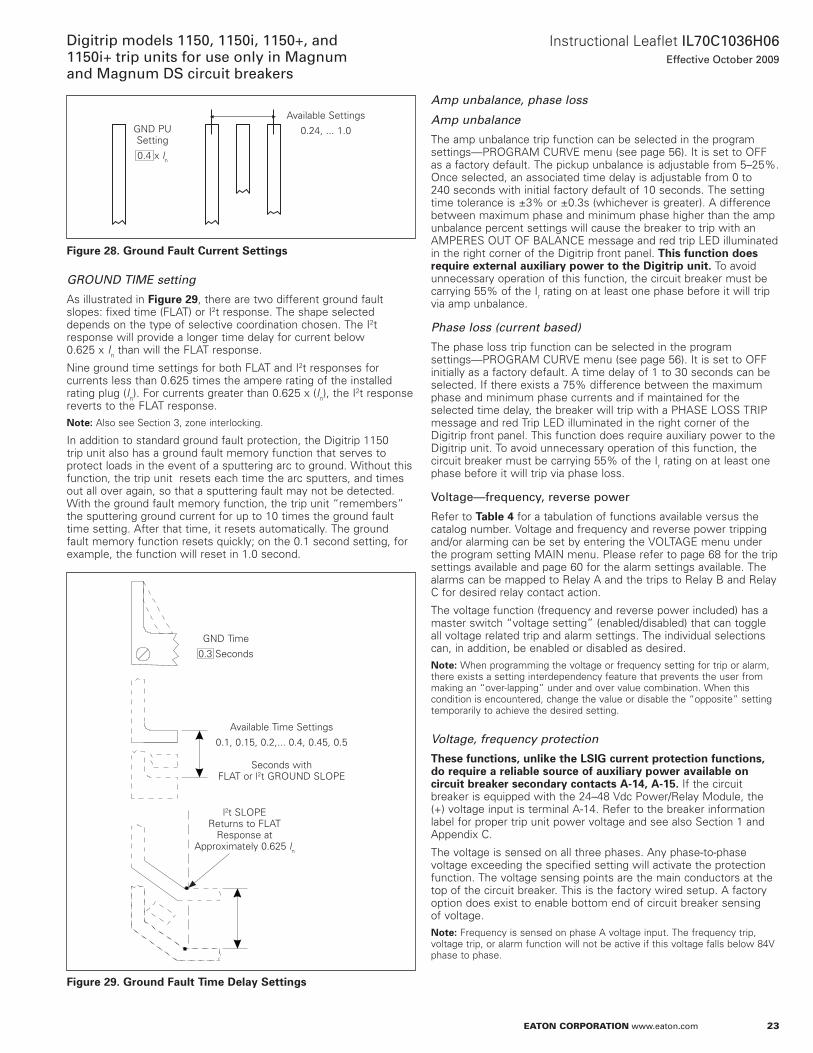
23
Instructional Leaflet IL70C1036H06Effective October 2009
Digitrip models 1150, 1150i, 1150+, and 1150i+ trip units for use only in Magnum and Magnum DS circuit breakers
eaton corporation www.eaton.com
Figure 28. Ground Fault Current Settings
GROUND TIME setting
as illustrated in Figure 29, there are two different ground fault slopes: fixed time (FLaT) or I2t response . The shape selected depends on the type of selective coordination chosen . The I2t response will provide a longer time delay for current below 0 .625 x In than will the FLaT response .
nine ground time settings for both FLaT and I2t responses for currents less than 0 .625 times the ampere rating of the installed rating plug (In) . For currents greater than 0 .625 x (In), the I2t response reverts to the FLaT response .
otee:N also see Section 3, zone interlocking .
In addition to standard ground fault protection, the Digitrip 1150 trip unit also has a ground fault memory function that serves to protect loads in the event of a sputtering arc to ground . Without this function, the trip unit resets each time the arc sputters, and times out all over again, so that a sputtering fault may not be detected . With the ground fault memory function, the trip unit “remembers” the sputtering ground current for up to 10 times the ground fault time setting . after that time, it resets automatically . The ground fault memory function resets quickly; on the 0 .1 second setting, for example, the function will reset in 1 .0 second .
Figure 29. Ground Fault Time Delay Settings
available Settings
0 .24, . . . 1 .0GnD PUSetting
0 .4 x ln
GnD Time
0 .3 Seconds
available Time Settings
0 .1, 0 .15, 0 .2, . . . 0 .4, 0 .45, 0 .5
Seconds with FLaT or l2t GRoUnD SLoPE
l2t SLoPEReturns to FLaT
Response at approximately 0 .625 ln
Amp unbalance, phase loss
Amp unbalance
The amp unbalance trip function can be selected in the program settings—PRoGRaM CURVE menu (see page 56) . It is set to oFF as a factory default . The pickup unbalance is adjustable from 5–25% . once selected, an associated time delay is adjustable from 0 to 240 seconds with initial factory default of 10 seconds . The setting time tolerance is ±3% or ±0 .3s (whichever is greater) . a difference between maximum phase and minimum phase higher than the amp unbalance percent settings will cause the breaker to trip with an aMPERES oUT oF BaLanCE message and red trip LED illuminated in the right corner of the Digitrip front panel . This function does require external auxiliary power to the Digitrip unit. To avoid unnecessary operation of this function, the circuit breaker must be carrying 55% of the Ir rating on at least one phase before it will trip via amp unbalance .
Phase loss (current based)
The phase loss trip function can be selected in the program settings—PRoGRaM CURVE menu (see page 56) . It is set to oFF initially as a factory default . a time delay of 1 to 30 seconds can be selected . If there exists a 75% difference between the maximum phase and minimum phase currents and if maintained for the selected time delay, the breaker will trip with a PHaSE LoSS TRIP message and red Trip LED illuminated in the right corner of the Digitrip front panel . This function does require auxiliary power to the Digitrip unit . To avoid unnecessary operation of this function, the circuit breaker must be carrying 55% of the Ir rating on at least one phase before it will trip via phase loss .
Voltage—frequency, reverse power
Refer to Table 4 for a tabulation of functions available versus the catalog number . Voltage and frequency and reverse power tripping and/or alarming can be set by entering the VoLTaGE menu under the program setting MaIn menu . Please refer to page 68 for the trip settings available and page 60 for the alarm settings available . The alarms can be mapped to Relay a and the trips to Relay B and Relay C for desired relay contact action .
The voltage function (frequency and reverse power included) has a master switch “voltage setting” (enabled/disabled) that can toggle all voltage related trip and alarm settings . The individual selections can, in addition, be enabled or disabled as desired .
otee:N When programming the voltage or frequency setting for trip or alarm, there exists a setting interdependency feature that prevents the user from making an “over-lapping” under and over value combination . When this condition is encountered, change the value or disable the “opposite” setting temporarily to achieve the desired setting .
Voltage, frequency protection
These functions, unlike the LSIG current protection functions, do require a reliable source of auxiliary power available on circuit breaker secondary contacts A-14, A-15. If the circuit breaker is equipped with the 24–48 Vdc Power/Relay Module, the (+) voltage input is terminal a-14 . Refer to the breaker information label for proper trip unit power voltage and see also Section 1 and appendix C .
The voltage is sensed on all three phases . any phase-to-phase voltage exceeding the specified setting will activate the protection function . The voltage sensing points are the main conductors at the top of the circuit breaker . This is the factory wired setup . a factory option does exist to enable bottom end of circuit breaker sensing of voltage .
otee:N Frequency is sensed on phase a voltage input . The frequency trip, voltage trip, or alarm function will not be active if this voltage falls below 84V phase to phase .
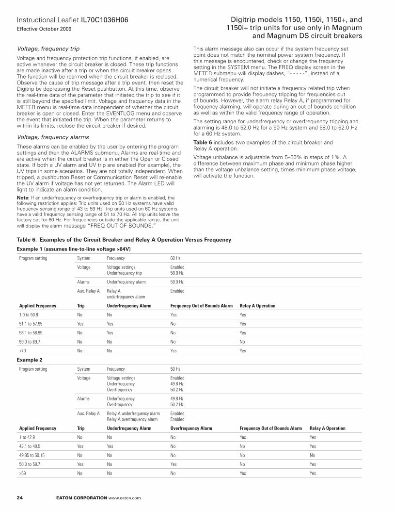
24
Instructional Leaflet IL70C1036H06Effective October 2009
Digitrip models 1150, 1150i, 1150+, and 1150i+ trip units for use only in Magnum
and Magnum DS circuit breakers
eaton corporation www.eaton.com
Voltage, frequency trip
Voltage and frequency protection trip functions, if enabled, are active whenever the circuit breaker is closed . These trip functions are made inactive after a trip or when the circuit breaker opens . The function will be rearmed when the circuit breaker is reclosed . observe the cause of trip message after a trip event, then reset the Digitrip by depressing the Reset pushbutton . at this time, observe the real-time data of the parameter that initiated the trip to see if it is still beyond the specified limit . Voltage and frequency data in the METER menu is real-time data independent of whether the circuit breaker is open or closed . Enter the EVEnTLoG menu and observe the event that initiated the trip . When the parameter returns to within its limits, reclose the circuit breaker if desired .
Voltage, frequency alarms
These alarms can be enabled by the user by entering the program settings and then the aLaRMS submenu . alarms are real-time and are active when the circuit breaker is in either the open or Closed state . If both a UV alarm and UV trip are enabled (for example), the UV trips in some scenarios . They are not totally independent . When tripped, a pushbutton Reset or Communication Reset will re-enable the UV alarm if voltage has not yet returned . The alarm LED will light to indicate an alarm condition .
otee:N If an underfrequency or overfrequency trip or alarm is enabled, the following restriction applies: Trip units used on 50 Hz systems have valid frequency sensing range of 43 to 59 Hz . Trip units used on 60 Hz systems have a valid frequency sensing range of 51 to 70 Hz . all trip units leave the factory set for 60 Hz . For frequencies outside the applicable range, the unit will display the alarm message “FREQ oUT oF BoUnDS .”
This alarm message also can occur if the system frequency set point does not match the nominal power system frequency . If this message is encountered, check or change the frequency setting in the SYSTEM menu . The FREQ display screen in the METER submenu will display dashes, “- - - - -“, instead of a numerical frequency .
The circuit breaker will not initiate a frequency related trip when programmed to provide frequency tripping for frequencies out of bounds . However, the alarm relay Relay a, if programmed for frequency alarming, will operate during an out of bounds condition as well as within the valid frequency range of operation .
The setting range for underfrequency or overfrequency tripping and alarming is 48 .0 to 52 .0 Hz for a 50 Hz system and 58 .0 to 62 .0 Hz for a 60 Hz system .
Table 6 includes two examples of the circuit breaker and Relay a operation .
Voltage unbalance is adjustable from 5–50% in steps of 1% . a difference between maximum phase and minimum phase higher than the voltage unbalance setting, times minimum phase voltage, will activate the function .
Table 6. Examples of the Circuit Breaker and Relay A Operation Versus Frequency
Example 1 (assumes line-to-line voltage >84V)
Program setting System Frequency 60 Hz
Voltage Voltage settings Underfrequency trip
Enabled58.0 Hz
Alarms Underfrequency alarm 59.0 Hz
Aux. Relay A Relay A underfrequency alarm
Enabled
Applied Frequency Trip Underfrequency Alarm Frequency Out of Bounds Alarm Relay A Operation
1.0 to 50.8 No No Yes Yes
51.1 to 57.95 Yes Yes No Yes
58.1 to 58.95 No Yes No Yes
59.0 to 69.7 No No No No
>70 No No Yes Yes
Example 2
Program setting System Frequency 50 Hz
Voltage Voltage settingsUnderfrequencyOverfrequency
Enabled49.8 Hz50.2 Hz
Alarms UnderfrequencyOverfrequency
49.8 Hz50.2 Hz
Aux. Relay A Relay A underfrequency alarm Relay A overfrequency alarm
EnabledEnabled
Applied Frequency Trip Underfrequency Alarm Overfrequency Alarm Frequency Out of Bounds Alarm Relay A Operation
1 to 42.9 No No No Yes Yes
43.1 to 49.5 Yes Yes No No Yes
49.85 to 50.15 No No No No No
50.3 to 58.7 Yes No Yes No Yes
>59 No No No Yes Yes
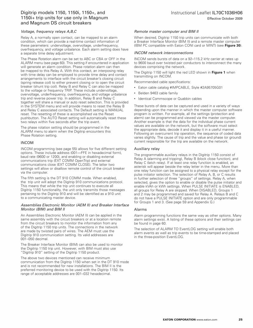
25
Instructional Leaflet IL70C1036H06Effective October 2009
Digitrip models 1150, 1150i, 1150+, and 1150i+ trip units for use only in Magnum and Magnum DS circuit breakers
eaton corporation www.eaton.com
Voltage, frequency relays A,B,C
Relay a, a normally open contact, can be mapped to an alarm condition, which can provide a real-time contact information of these parameters: undervoltage, overvoltage, underfrequency, overfrequency, and voltage unbalance . Each alarm setting does have a separate time delay adjustment .
The Phase Rotation alarm can be set to aBC or CBa or oFF in the aLaRM menu (see page 60) . This setting if encountered in application will generate an alarm condition . Phase rotation alarm can then be mapped to this Relay a . With this contact, an interposing relay with time delay can be employed to provide time delay and contact arrangements to interface with the circuit breaker’s closing circuit (spring release coil) to either prevent closing or to open the circuit breaker (shunt trip coil) . Relay B and Relay C can also be mapped to the voltage or frequency TRIP . These include undervoltage, overvoltage, underfrequency, overfrequency, and voltage unbalance trip and reverse power trip . In addition, Relay B and Relay C together will share a manual or auto reset selection . This is provided in the SYSTEM menu and will provide means to reset the Relay B and Relay C associated contacts . The Default setting is ManUaL reset . The resetting of these is accomplished via the Reset pushbutton . The aUTo Reset setting will automatically reset these two relays within five seconds after the trip event .
The phase rotation setting should be programmed in the aLaRM menu to alarm when the Digitrip encounters this Phase Rotation setting .
INCOM
InCoM programming (see page 55) allows for five different setting options . These include address (001—FFE in hexadecimal form), baud rate (9600 or 1200), and enabling or disabling external communications trip (ExT CoMM openTrip) and external communications close (ExT CoMM CLoSE) . The latter two settings will allow or disallow remote control of the circuit breaker via the computer .
The fifth setting is the DT 910 CoMM mode . When enabled, the trip unit will adopt the Digitrip 910 communications protocol . This means that while the trip unit continues to execute all Digitrip 1150 functionality, the unit only transmits those messages pertaining to the Digitrip 910 and will be identified as a 910 unit to a communicating master device .
Assemblies Electronic Monitor (AEM II) and Breaker Interface Monitor (BIM) and BIM II
an assemblies Electronic Monitor (aEM II) can be applied in the same assembly with the circuit breakers or at a location remote from the circuit breakers to monitor the information from any of the Digitrip 1150 trip units . The connections in the network are made by twisted pairs of wires . The aEM must use the Digitrip 910 communication setting . Its valid addresses are 001–050 decimal .
The Breaker Interface Monitor (BIM) can also be used to monitor the Digitrip 1150 trip unit . However, with BIM must also use “Digitrip 910” setting of the Digitrip 1150 product .
The above two devices mentioned can receive minimum communication from the Digitrip 1150 when set in the DT 910 mode and is not recommended for new installations . The BIM II is the preferred monitoring device to be used with the Digitrip 1150 . Its range of acceptable addresses are 001–032 hexadecimal .
Remote master computer and BIM II
When desired, Digitrip 1150 trip units can communicate with both a Breaker Interface Monitor (BIM II) and a remote master computer (IBM PC compatible with Eaton ConI card or MInT) (see Figure 30) .
INCOM network interconnections
InCoM sends bursts of data on a 92–115 .2 kHz carrier at rates up to 9600 baud over twisted pair conductors to interconnect the many devices comprising the network .
The Digitrip 1150 will light the red LED shown in Figure 1 when transmitting on InCoM .
Recommended cable specifications:• Eaton cable catalog #IMPCaBLE, Style #2a95705G01• Belden 9463 cable family• Identical Commscope or Quabbin cables
These bursts of data can be captured and used in a variety of ways depending upon the manner in which the master computer software program is written . For example, all the settings (protection and alarm) can be programmed and viewed via the master computer . another example is that the data for the individual phase current values are available on the network, but the software must select the appropriate data, decode it and display it in a useful manner . Following an overcurrent trip operation, the sequence of coded data varies slightly . The cause of trip and the value and phase (or ground) current responsible for the trip are available on the network .
Auxiliary relay
The programmable auxiliary relays in the Digitrip 1150 consist of Relay a (alarming and tripping), Relay B (block close function), and Relay C (latch relay) . If at least one relay function is enabled, an asterisk will appear beside the relay letter in the menu . More than one relay function can be assigned to a physical relay except for the pulse initiator selection . The selection of Relay a, B, or C results in further selection of three “groups” of settings . Relay a, when selected, gives the option to enable or disable the pulse initiator and enable kVah or kWh settings . When PULSE InITIaTE is EnaBLED, all groups for Relay a are skipped . When DISaBLED, Groups 1 and 2 may be programmed and saved for Relay a . Relays B and C do not have a PULSE InITIaTE option and are only programmable for Groups 1 and 3 . (See page 59 and appendix G .)
Alarms
alarm programming functions the same way as other options . Many alarm settings exist . a listing of these options and their settings can be found in page 60 .
The selection of aLaRM To EventLoG setting will enable both alarm events as well as trip events to be time-stamped and placed in the three-position EventLoG .
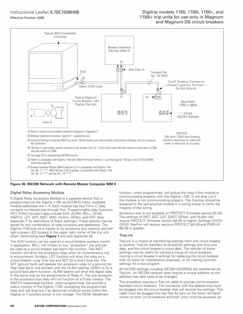
26
Instructional Leaflet IL70C1036H06Effective October 2009
Digitrip models 1150, 1150i, 1150+, and 1150i+ trip units for use only in Magnum
and Magnum DS circuit breakers
eaton corporation www.eaton.com
Figure 30. INCOM Network with Remote Master Computer BIM II
0 0 21234
(Y)
(BL)
0 0 1
Typical IBM Compatible Computer
Breaker Interface Monitor (BIM II)
See View aTwisted Pair . no . 18 aWG
Baud Rate 1200 or 9600
Cutoff Shield or Connect to Unused Customer Terminal—
Do not Ground
3-Digit InCoM address
Eaton ConI Card
Typical Magnum Circuit Breaker with
Digitrip Trip Unit
View a
noTICE 100 ohm 1/2W terminating
resistor required on network even if network is unused
a Refer to master circuit breaker connection diagrams in Appendix C.b Modular telephone connector, Type RJ11, supplied by user.c Ground shielding at computer BIM II as shown. Where devices are daisy-chained, interconnect shielding, but do not ground
the connection.d 100 ohm ½ watt carbon resistor required at last breaker. See T.D. 17-513. Also insert 100 ohm resistor to terminator at CONI
card (via switch on CONI).e See page 55 for programming INCOM function.f AEM II is compatible with Digitrip 1150 with AEM II firmware Version 7.1 and the Digitrip 1150 set in the DT 910 COMM
mode (see page 55).g Breaker Interface Module (BIM II) Version 3.12 is compatible with Digitrip 1150
Cat. No. 11 ****. BIM II Version 3.20 or greater is compatible with Digitrip 1150 Cat. No. 11 **** and Cat. No. 11P ****.
a
a d Res .
b d
c
c
Digital Relay Accessory Module
a Digital Relay accessory Module is a separate device that is programmed via the Digitrip 1150 via aCCBUS menu . available module addresses are 1–4 . Each module has four Form C relay contacts numbered one through four . Programmable relay functions (RLY FUnC) for each relay include aUx, aLRM, BELL, DEaD, WaTCH, LDT, SDT, InST, GnD, HLalm, GFalm, and oFF . (See appendix F for definitions of these settings .) These options may be saved for any combination of relay functions and addresses . The Digitrip 1150 acts as a master to its accessory bus network and will light a green LED located in the upper right corner of the trip unit when transmitting (see Figure 1 and also appendix H) .
The aUx function can be used as a circuit breaker auxiliary switch in application . BELL will initiate on any “protection” trip and can be used as a circuit breaker bell alarm trip function . The InST function will drive the accessory relay when an instantaneous trip is encountered . Similarly, LDT function will drive the relay on a circuit breaker Long Time trip and SDT for a short time trip . The GFT (ground fault) will operate the accessory relay on a ground trip . High load alarm will activate with the HLalm setting . GFalm is for a ground fault alarm function . aLRM (alarm) will drive the digital relay in the same way as the assignments of Relay a . The one exception is the accessory bus relay will not function as a Pulse Initiator . The WaTCH (watchdog) function, when programmed, can provide a status monitor of the Digitrip 1150, energizing the programmed relay and will drop out if an abnormal condition exists within the Digitrip or if auxiliary power is low voltage . The DEaD (deadman)
function, when programmed, will pickup the relay if the module is communicating properly with the Digitrip 1150 . It will drop out if the module is not communicating properly . This function should be assigned to the last physical module in a wiring lineup to verify the integrity of the wiring .
accessory bus is not available on PRoTECT firmware version 8a .00 . The settings of InST, SDT, LDT, GnDT GFalm, and HLalm will require PRoTECT firmware version 8a .05 or higher . Settings oV/UV, oF/UF, RevPwr will require versions PRoTECT 8a .09 and DISPLaY 8B .09 or greater .
TripLink
TripLink is a means of transferring settings from one circuit breaker to another . TripLink transfers all protection settings and time and date, and the circuit breaker’s circuit data . The transfer of these settings may be useful for cloning a lineup of circuit breakers, cloning a circuit breaker’s settings for replacing the circuit breaker with its clone for maintenance purposes, or for making common settings for a test program .
all InCoM settings including InCoM aDDRESS are transferred via TripLink . an InCoM network does require a unique address so the address may later have to be changed .
The procedure requires a TripLink cable to provide communication between circuit breakers . The connector with the labeled end must be plugged into the circuit breaker that will receive the settings . This cable must be plugged into the Test Kit pins on the lower left-hand corner on both circuit breakers and both units must be powered up
27
Instructional Leaflet IL70C1036H06Effective October 2009
Digitrip models 1150, 1150i, 1150+, and 1150i+ trip units for use only in Magnum and Magnum DS circuit breakers
eaton corporation www.eaton.com
for the setting transfer to be successful . If power is not available, then use separate auxiliary Power Module Cat . no . PRTaaPM and energize the unit by plugging keyed connector into upper right corner of the Digitrip 1150 (see Figure 1 and Figure 31) .
otee:N a TripLink cable when installed will disconnect that unit from the InCoM communication network .
Figure 31. TripLink Transfer
Preliminary requirements
1. Both units must be Digitrip 1150 and both must have the same Catalog (cat .) number, plug ampere rating for a successful transfer .
otee:N It is recommended that both the sending and receiving units be the same firmware revision . Three cases exist: a . Units with revision 0 are only compatible with other revision 0 units . b . Units with revision 9 are only compatible with other revision 9 units . c . When transferring settings having different firmware revisions will transfer all the protection settings properly . However, the accessory bus settings should be verified .
2. To send settings, the receiving circuit breaker must be in open state and without line voltage on the circuit breaker’s main terminals .
Transfer procedure
otee:N It is important to realize that the transfer must be performed from the RECEIVInG circuit breaker (the circuit breaker with the white connector marked “This unit to receive setpoints”) .
In the PRoGRaM TRIPLInK menu, if all preliminary requirements are met, the Digitrip 1150 display on the receiving circuit breaker will read “THIS UnIT To RECEIVE .” otherwise, an error message will appear reading “TripLink ConFIG ERRoR” and the display will return to PRoGRaM SETTInGS menu .
If the circuit breakers meet the preliminary requirements, the user will be prompted to “PRESS SaVE To LEaRn .” When Save is pressed, settings will transfer and a “LoaDInG” message will appear on the display screen . Transfer will be confirmed if successful with a “TripLink TRanSFER CoMPLETE” message . otherwise, “TripLink TRanSFER ERRoR” will appear on the display .
In the event of TripLink Configuration Error, check all preliminary requirements as well as the TripLink cable connections . also ensure that transfer is being initiated and performed on the receiving circuit breaker .
Setting time
In the Digitrip 1150, dates are displayed in DD-MmmYY format (for example, 12 Mar 98) and time is displayed in military-style format with hours from 0–23 . The first screen in PGM SET\TIME is a view-only screen showing the current time setting for the unit . The View Down button changes screens to the DaY programming screen where the two-digit date can be adjusted with the Edit Up or Edit Down pushbuttons . View Down then moves through the programmable three-character MonTH abbreviation, two-digit YEaR selection, two-digit HoURS, and two-digit MInUTES that are all programmed with the Edit Up and/or Edit Down pushbuttons . Seconds are not programmable and begin at 00 when time settings are saved . Using View Up in the menu will move the user through the settings in reverse order as described above (refer to page 63) .
Selecting displays
Display programming options control the screens displayed in the METER menu . Program display is located in the PGM SET\DISPLaY submenu . This submenu lists 22 programmable screens . The first screen sets metering for a, B, and C phase currents to aUTo or ManUaL . The remaining 21 screens of various perameters can be set to on or oFF, depending on user preference . any settings turned to oFF will not be displayed when METER is selected from the MaIn menu (refer to page 58) .
System settings
Frequency
This setting is to reflect the power system’s operating frequency of 50 or 60 Hz . The factory default is 60 Hz .
BC relay reset
This setting is to define the reset mode of Relay B and Relay C of the Digitrip’s Power Relay Module . The selections are aUTo or ManUaL reset (see Section 4) .
Sliding demand
a sliding demand calculation can be chosen for either the maximum kW demand or the maximum kVa demand . If neither is required, the user can choose oFF by pressing the up/down Edit Value keys .
Waveform capture
The waveform capture function can be enabled on a 1-, 5-, or 10-minute basis . It can also be disabled by selecting oFF with the Edit Value keys . If the THD alarm setting has been enabled in the aLaRMS menu, the waveform capture function will automatically be set to one minute and the waveform capture oFF setting will not be available .
View settings (VIEW SET)
The VIEW SET menu will allow the user to view all of the settings presented in the PGM SET menus with the exception of the TripLink function . The user cannot edit or change settings in these menus .
FIRMwARE menu
The FIRMWaRE menu enables the user to view the version and revision of the trip unit firmware . The protection firmware is displayed as PRoTECT while DISPLaY firmware can be viewed by pressing the up/down View function keys .
28
Instructional Leaflet IL70C1036H06Effective October 2009
Digitrip models 1150, 1150i, 1150+, and 1150i+ trip units for use only in Magnum
and Magnum DS circuit breakers
eaton corporation www.eaton.com
METER menu
The METER menu initially will show six screens of data via the factory display setup . They are phase current, neutral and ground currents (if supplied), phase voltages, forward power, power factor and frequency, and energy values . However, the PRoGRaM DISPLaY menu can be used to present metered data relevant to a specific customer application . There are 22 data screens selectable as listed on page 45 and page 58 .
The demand and the average, minimum and maximum current screens alternate between the data and additional information concerning the measured parameter . The minimum and maximum phase currents are actually reset as a group (see page 45) . The oP CoUnT screen displays circuit breaker operation where an open/close is registered as one count . The oP CoUnT can be reset also when this screen is active .
HARMONIC menu
The Digitrip 1150 HaRMonIC menu provides capabilities to calculate and display the total harmonic distortion (THD) for phase currents Ia, IB, and IC as well as In if available . The term THD is used to define the amount of harmonic current that the breaker is seeing or the system is experiencing in percentage of the power frequency current . This can be useful in troubleshooting to detect individual circuit breaker current loads that could lead to system problems and early equipment failure . The equation used for calculating THD is:
Where Irms is the rms current of the waveform and I1 is the rms current of the fundamental frequency .
For example, the THD calculation for a load having an equal rms value of the fundamental and third harmonic current would have a THD value of 100% . This would be a large value of THD and would not be typical .
In addition to individually displaying the THD for the phase currents, the Digitrip 1150 will also display the individual harmonic currents up through the 27th harmonic .
Local operation on the Digitrip to observe this data is done using the View Down pushbutton of the Digitrip .
By selecting HaRMonIC from the MaIn menu, a waveform capture event and harmonic data calculation is accomplished locally . a second way is to automatically generate waveform capture on a 1-minute, 5-minute, 10-minute, or oFF basis by selecting GEnERaL in the PRoGRaM SETTInGS submenu and scrolling to the WaVEFoRM CaPTURE option . The third way is to remotely trigger the waveform capture via a Powernet communication command . For these three types of captures, the Digitrip 1150 will provide per harmonic data . For trip events and alarm events, the per harmonic analysis is not provided . Powernet software screens are available to show waveform capture oscillographs of each phase as well as bar graphs of the magnitudes and individual harmonics that make up the three-phase currents (see Section 4) .
If less than 15% of the rating plug current is applied to the circuit breaker, the trip unit will display three dashed lines (‘- - -’) for the THD and Crest Factor values since these cannot accurately be measured .
Event log
The Digitrip 1150 trip unit has the ability to record the cause, timestamp, and associated current or related data for a maximum of three events . an event is defined as an alarm or trip condition experienced by the circuit breaker . The user has the option to record only trip function events or to record both trip and alarm functions by manipulating the alarm to EventLoG set point located in the aLaRMS PRoGRaMMInG menu . The event data is stored in nonvolatile RaM and is maintained on a first-in, first-out basis . In the case where the alarm to EventLoG setting is enabled, a new alarm event will replace either historic trip or historic alarm condition stored previously (see page 45) .
Power and energy parameters
Power has approximately a 1-second update rate and is shown as forward or reverse power in kW units . The parameters kVa and kvar are also updated in a similar time period . Demand kW is presented as forward or reverse in kW units and is based on the last average 5-minute interval . Demand kVa is also based on the last average 5-minute interval . These parameters can be reset when this screen is in view and the Reset pushbutton action will start a new 5-minute period . Programming alarms (kW or kVa) to exceed a threshold value will produce an alarm . a timestamp is also provided if the alarm to EventLoG setting is enabled .
Demand maximum kW and demand maximum kVa are peak values that have been encountered since the last Reset of these parameters . a pushbutton Reset or InCoM Reset will start a new 15-minute interval . as a factory default, both kW and kVa demands are set for a “fixed” 15-minute window . The update rate for the calculation is 15 minutes . a “Sliding” window calculation is a possible setting that will calculate a continuous new demand value and update the value if a new maximum is encountered every minute . This SLIDInG DEManD setting is the first item in the SYSTEM (or GEnERaL) screen .
The Digitrip 1150 will display locally in kWh units of both forward and reverse energy values . an additional energy parameter is kVah . The rollover energy value is 9,999,999 for both .
The auxiliary Relay a can be assigned to a pulse Initiator function for either kVah or kWh . When this feature is selected, Relay a will be dedicated for pulse initiator and no other relay function is possible for Relay a (see page 59) . The pulse initiator provides a contact change of state to an external counter device whenever a value is exceeded . This pulse value is based on an anSI document and is expressed as the general equation:
Pulse Value (kVA or kW) = 0 .000717 x In (plug amperes)
Power quality
The Digitrip 1150 in a Magnum circuit breaker can measure a variety of parameters relating to today’s modern power system . This data can be viewed locally or via a computer remotely in which case the data can be logged .
Power factor, THD and crest factor (CF)
The system power factor is a real-time measurement with approximately a one second update rate . The tolerance is the value ± 0 .02 . Maximum PF and minimum PF values are historic values that are held until reset .
Total harmonic distortion (THD) of each phase and neutral (if valid) and corresponding per harmonic data up to the 27th harmonic and crest factor are available via a waveform capture trigger . This waveform capture trigger can be done locally by selecting HaRMonIC in the MaIn menu or by exceeding a THD alarm threshold programmed by the user . See Section 4 .
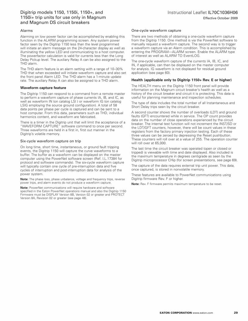
29
Instructional Leaflet IL70C1036H06Effective October 2009
Digitrip models 1150, 1150i, 1150+, and 1150i+ trip units for use only in Magnum and Magnum DS circuit breakers
eaton corporation www.eaton.com
Alarms
alarming on low power factor can be accomplished by enabling this function in the aLaRM programming screen . any system power factor seen by the Digitrip 1150 less than the level programmed will initiate an alarm message on the 24-character display as well as illuminating the yellow LED and communicating to a host computer . The powerfactor calculation is valid for currents less than the Long Delay Pickup level . The auxiliary Relay a can be also assigned to the THD alarm .
The THD alarm feature is an alarm setting with a range of 10–30% THD that when exceeded will initiate waveform capture and also set the front panel alarm LED . The THD alarm has a 1-minute update rate . The auxiliary Relay a can also be assigned to a THD alarm .
Waveform capture feature
The Digitrip 1150 can respond to a command from a remote master to perform a waveform capture of phase currents Ia, IB, and IC, as well as waveform In (on catalog LSI ) or waveform IG (on catalog LSIG employing the source ground configuration) . a total of 58 data points per phase per cycle is captured and can be sent to a host computer . From this data, parameters such as THD, individual harmonics content, and waveform are fabricated .
There is a timer in the Digitrip unit that will limit the acceptance of a “WaVEFoRM CaPTURE” software command to once per second . Three waveforms are held in a first in, first out manner in the Digitrip’s volatile memory .
Six-cycle waveform capture on trip
on long time, short time, instantaneous, or ground fault tripping events, the Digitrip 1150 will capture the curve waveforms to a buffer . The buffer as a waveform can be displayed on the master computer using the Powernet software screen (Ref . I .L .17384 for protocol and software commands) . The six-cycle waveform capture will typically contain one cycle of pre-interruption data and five cycles of interruption and post-interruption data for analysis of the power system .
otee:N The phase loss, phase unbalance, voltage and frequency trips, reverse power trips, and alarm events do not produce a waveform capture .
otee:N Powernet communications will require hardware and software specified in the Eaton Powernet operations manual and also the Digitrip 1150 Firmware must be DISPLaY Version 8B, Version 02 or greater and PRoTECT Version 8a, Revision 02 or greater (see page 48) .
One-cycle waveform capture
There are two methods of obtaining a one-cycle waveform capture from the Digitrip 1150 . one method is via the Powernet software to manually request a waveform capture . The second way is to trigger a waveform capture via an alarm condition . This is accomplished by entering the PRoGRaM—aLaRM screen . Enable the aLaRM type of interest as well as aLaRM To EventLoG .
The one-cycle waveform capture of the currents Ia, IB, IC, and In, if applicable, can then be displayed on the master computer for analysis . IG waveform is not displayed for residual ground application (see page 60) .
Health (applicable only to Digitrip 1150+ Rev. E or higher)
The HEaLTH menu on the Digitrip 1150 front panel will provide information on the Magnum circuit breaker’s health as well as a history of the circuit breaker and circuit it is protecting . This data is useful for planning maintenance and inspection schedules .
The type of data includes the total number of all Instantaneous and Short Delay trips seen by the circuit breaker .
a second counter shows the number of overloads (LDT) and ground faults (GFT) encountered while in service . The oP count provides data on the number of close operations experienced by the circuit breaker . The internal test function will not increment the InST/SD or the LDT/GFT counters, however, there will be count values in these registers from the factory primary injection testing . Each of these three values can be zeroed by depressing the Reset pushbutton . These counters will roll over at a value of 255 . The operation counter will roll over at 65,000 .
The last time the circuit breaker was operated (open or closed or tripped) is viewable with time and date displayed . also included is the maximum temperature in degrees centigrade as seen by the Digitrip microprocessor CHip (for screen presentations, see page 69) .
The capture of the data requires external trip unit power . This data, once captured, is stored in nonvolatile memory .
These features are available to Powernet communications using Digitrip firmware Rev . F or higher .
otee:N Rev . F firmware permits maximum temperature to be reset .
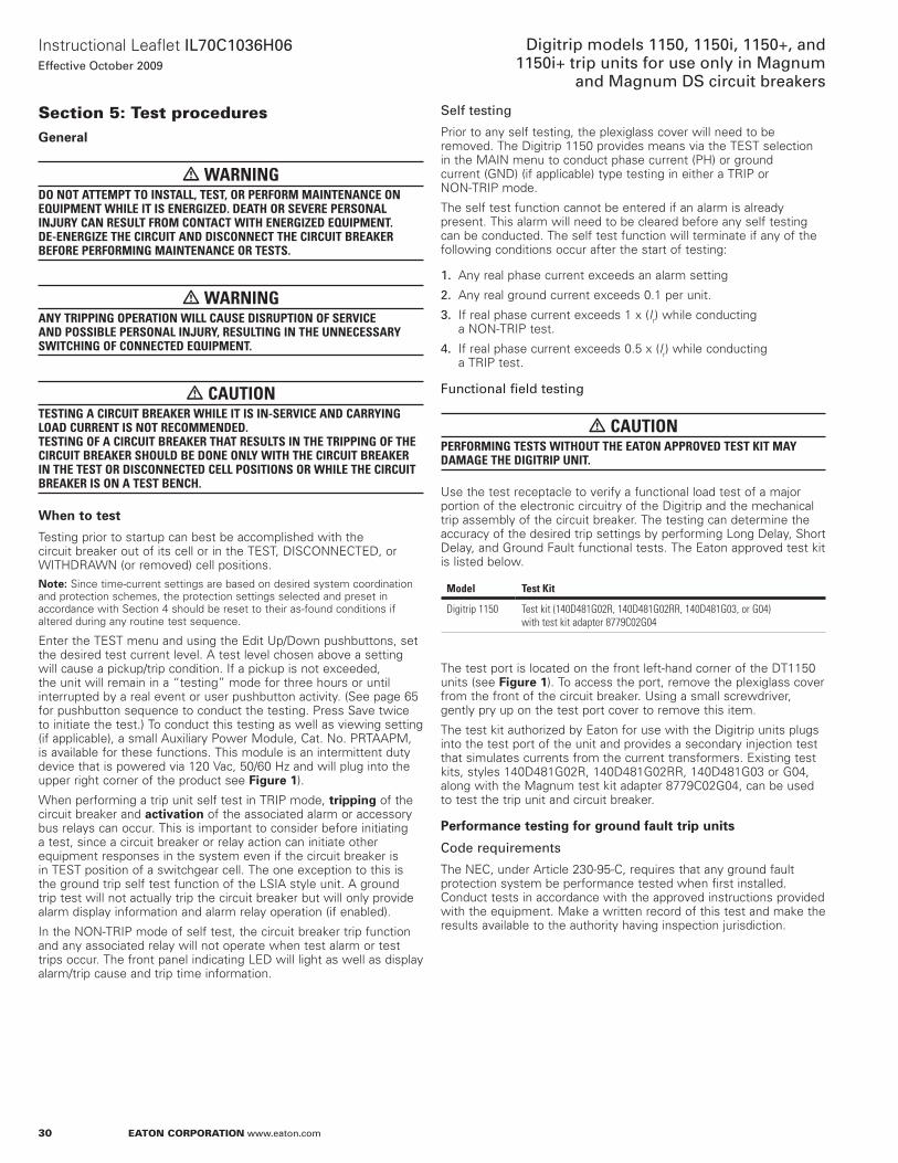
30
Instructional Leaflet IL70C1036H06Effective October 2009
Digitrip models 1150, 1150i, 1150+, and 1150i+ trip units for use only in Magnum
and Magnum DS circuit breakers
eaton corporation www.eaton.com
Section 5: test proceduresGeneral
m WARNINGDO NOT ATTEMPT TO INSTALL, TEST, OR PERFORM MAINTENANCE ON EQUIPMENT WHILE IT IS ENERGIZED. DEATH OR SEVERE PERSONAL INJURY CAN RESULT FROM CONTACT WITH ENERGIZED EQUIPMENT. DE-ENERGIZE THE CIRCUIT AND DISCONNECT THE CIRCUIT BREAkER BEFORE PERFORMING MAINTENANCE OR TESTS.
m WARNINGANY TRIPPING OPERATION WILL CAUSE DISRUPTION OF SERVICE AND POSSIBLE PERSONAL INJURY, RESULTING IN THE UNNECESSARY SWITCHING OF CONNECTED EQUIPMENT.
m CAUTIONTESTING A CIRCUIT BREAkER WHILE IT IS IN-SERVICE AND CARRYING LOAD CURRENT IS NOT RECOMMENDED. TESTING OF A CIRCUIT BREAkER THAT RESULTS IN THE TRIPPING OF THE CIRCUIT BREAkER SHOULD BE DONE ONLY WITH THE CIRCUIT BREAkER IN THE TEST OR DISCONNECTED CELL POSITIONS OR WHILE THE CIRCUIT BREAkER IS ON A TEST BENCH.
When to test
Testing prior to startup can best be accomplished with the circuit breaker out of its cell or in the TEST, DISConnECTED, or WITHDRaWn (or removed) cell positions .
otee:N Since time-current settings are based on desired system coordination and protection schemes, the protection settings selected and preset in accordance with Section 4 should be reset to their as-found conditions if altered during any routine test sequence .
Enter the TEST menu and using the Edit Up/Down pushbuttons, set the desired test current level . a test level chosen above a setting will cause a pickup/trip condition . If a pickup is not exceeded, the unit will remain in a “testing” mode for three hours or until interrupted by a real event or user pushbutton activity . (See page 65 for pushbutton sequence to conduct the testing . Press Save twice to initiate the test .) To conduct this testing as well as viewing setting (if applicable), a small auxiliary Power Module, Cat . no . PRTaaPM, is available for these functions . This module is an intermittent duty device that is powered via 120 Vac, 50/60 Hz and will plug into the upper right corner of the product see Figure 1) .
When performing a trip unit self test in TRIP mode, tripping of the circuit breaker and activation of the associated alarm or accessory bus relays can occur . This is important to consider before initiating a test, since a circuit breaker or relay action can initiate other equipment responses in the system even if the circuit breaker is in TEST position of a switchgear cell . The one exception to this is the ground trip self test function of the LSIa style unit . a ground trip test will not actually trip the circuit breaker but will only provide alarm display information and alarm relay operation (if enabled) .
In the non-TRIP mode of self test, the circuit breaker trip function and any associated relay will not operate when test alarm or test trips occur . The front panel indicating LED will light as well as display alarm/trip cause and trip time information .
Self testing
Prior to any self testing, the plexiglass cover will need to be removed . The Digitrip 1150 provides means via the TEST selection in the MaIn menu to conduct phase current (PH) or ground current (GnD) (if applicable) type testing in either a TRIP or non-TRIP mode .
The self test function cannot be entered if an alarm is already present . This alarm will need to be cleared before any self testing can be conducted . The self test function will terminate if any of the following conditions occur after the start of testing:
1. any real phase current exceeds an alarm setting
2. any real ground current exceeds 0 .1 per unit .
3. If real phase current exceeds 1 x (Ir) while conducting a non-TRIP test .
4. If real phase current exceeds 0 .5 x (Ir) while conducting a TRIP test .
Functional field testing
m CAUTIONPERFORMING TESTS WITHOUT THE EATON APPROVED TEST kIT MAY DAMAGE THE DIGITRIP UNIT.
Use the test receptacle to verify a functional load test of a major portion of the electronic circuitry of the Digitrip and the mechanical trip assembly of the circuit breaker . The testing can determine the accuracy of the desired trip settings by performing Long Delay, Short Delay, and Ground Fault functional tests . The Eaton approved test kit is listed below .
Model Test kit
Digitrip 1150 Test kit (140D481G02R, 140D481G02RR, 140D481G03, or G04) with test kit adapter 8779C02G04
The test port is located on the front left-hand corner of the DT1150 units (see Figure 1) . To access the port, remove the plexiglass cover from the front of the circuit breaker . Using a small screwdriver, gently pry up on the test port cover to remove this item .
The test kit authorized by Eaton for use with the Digitrip units plugs into the test port of the unit and provides a secondary injection test that simulates currents from the current transformers . Existing test kits, styles 140D481G02R, 140D481G02RR, 140D481G03 or G04, along with the Magnum test kit adapter 8779C02G04, can be used to test the trip unit and circuit breaker .
Performance testing for ground fault trip units
Code requirements
The nEC, under article 230-95-C, requires that any ground fault protection system be performance tested when first installed . Conduct tests in accordance with the approved instructions provided with the equipment . Make a written record of this test and make the results available to the authority having inspection jurisdiction .
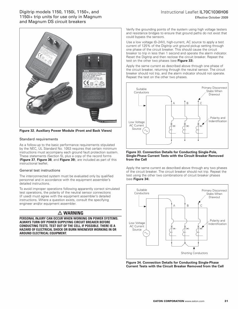
31
Instructional Leaflet IL70C1036H06Effective October 2009
Digitrip models 1150, 1150i, 1150+, and 1150i+ trip units for use only in Magnum and Magnum DS circuit breakers
eaton corporation www.eaton.com
Figure 32. Auxiliary Power Module (Front and Back Views)
Standard requirements
as a follow-up to the basic performance requirements stipulated by the nEC, UL Standard no . 1053 requires that certain minimum instructions must accompany each ground fault protection system . These statements (Section 5), plus a copy of the record forms (Figure 37, Figure 38, and Figure 39), are included as part of this instructional leaflet .
General test instructions
The interconnected system must be evaluated only by qualified personnel and in accordance with the equipment assembler’s detailed instructions .
To avoid improper operations following apparently correct simulated test operations, the polarity of the neutral sensor connections (if used) must agree with the equipment assembler’s detailed instructions . Where a question exists, consult the specifying engineer and/or equipment assembler .
m WARNINGPERSONAL INJURY CAN OCCUR WHEN WORkING ON POWER SYSTEMS. ALWAYS TURN OFF POWER SUPPLYING CIRCUIT BREAkER BEFORE CONDUCTING TESTS. TEST OUT OF THE CELL, IF POSSIBLE. THERE IS A HAZARD OF ELECTRICAL SHOCk OR BURN WHENEVER WORkING IN OR AROUND ELECTRICAL EQUIPMENT.
Verify the grounding points of the system using high voltage testers and resistance bridges to ensure that ground paths do not exist that could bypass the sensors .
Use a low voltage (0–24V), high-current, aC source to apply a test current of 125% of the Digitrip unit ground pickup setting through one phase of the circuit breaker . This should cause the circuit breaker to trip in less than 1 second and operate the alarm indicator . Reset the Digitrip and then reclose the circuit breaker . Repeat the test on the other two phases (see Figure 33) .
apply the same current as described above through one phase of the circuit breaker, returning through the neutral sensor . The circuit breaker should not trip, and the alarm indicator should not operate . Repeat the test on the other two phases .
Figure 33. Connection Details for Conducting Single-Pole, Single-Phase Current Tests with the Circuit Breaker Removed from the Cell
apply the same current as described above through any two phases of the circuit breaker . The circuit breaker should not trip . Repeat the test using the other two combinations of circuit breaker phases (see Figure 34) .
Figure 34. Connection Details for Conducting Single-Phase Current Tests with the Circuit Breaker Removed from the Cell
Suitable Conductors
Low Voltage aC Current
Source
Polarity and Indentification
Primary Disconnect Stabs When
Drawout
a B C
Suitable Conductors
Low Voltage aC Current
Source
Polarity and Indentification
Primary Disconnect Stabs When
Drawout
a B C
Shorting Conductors
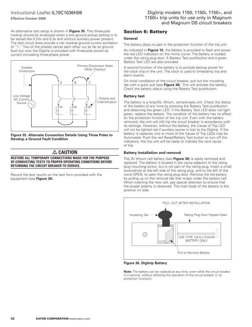
32
Instructional Leaflet IL70C1036H06Effective October 2009
Digitrip models 1150, 1150i, 1150+, and 1150i+ trip units for use only in Magnum
and Magnum DS circuit breakers
eaton corporation www.eaton.com
an alternative test setup is shown in Figure 35 . This three-pole hookup should be employed when a low ground pickup setting is to be tested like 0 .24x and 0 .3x and without auxiliary power present . The test circuit does provide a net residual ground current excitation of “1 .” Two of the phases cancel each other out as far as ground fault but now the Digitrip is provided with three-pole power-up current simulating three-phase power .
Figure 35. Alternate Connection Details Using Three Poles to Develop a Ground Fault Condition
m CAUTIONRESTORE ALL TEMPORARY CONNECTIONS MADE FOR THE PURPOSE OF CONDUCTING TESTS TO PROPER OPERATING CONDITIONS BEFORE RETURNING THE CIRCUIT BREAkER TO SERVICE.
Record the test results on the test form provided with the equipment (see Figure 39) .
Suitable Conductors
Low Voltage aC Current
SourcePolarity and
Indentification
Primary Disconnect Stabs When Drawout
a B C
Section 6: BatteryGeneral
The battery plays no part in the protection function of the trip unit .
as indicated in Figure 15, the battery is provided to flash and power the red LED indication on the mimic curve . The battery is located under the rating plug door . a Battery Test pushbutton and a green Battery Test LED are also provided .
a second function of the battery is to provide backup power for the clock chip in the unit . The clock is used to timestamp trip and alarm events .
on initial installation of the circuit breaker, pull out the insulating tab with a quick pull (see Figure 36) . This will activate the battery . Check the battery status using the Battery Test pushbutton .
Battery test
The battery is a long-life, lithium, camera-type unit . Check the status of the battery at any time by pressing the Battery Test pushbutton and observing the green LED . If the Battery Test LED does not light green, replace the battery . The condition of the battery has no effect on the protection function of the trip unit . Even with the battery removed, the unit will still trip the circuit breaker in accordance with its settings . However, without the battery, the Cause of Trip LED will not be lighted red if auxiliary power is lost to the Digitrip . If the battery is replaced, one or more of the Cause of Trip LEDs may be illuminated . Push the red Reset/Battery Test button to turn off the indicators; the trip unit will be ready to indicate the next cause of trip .
Battery installation and removal
The 3V lithium cell battery (see Figure 36) is easily removed and replaced . The battery is located in the cavity adjacent to the rating plug mounting screw, but is not part of the rating plug . Insert a small screwdriver at the left side of the rating plug, and to the left of the word oPEn, to open the rating plug door . Remove the old battery by pulling up on the removal tab that wraps under the battery cell . When inserting the new cell, pay special attention to ensure that the proper polarity is observed . The main body of the battery is the positive (+) side .
Figure 36. Digitrip Battery
otee:N The battery can be replaced at any time, even while the circuit breaker is in-service, without affecting the operation of the circuit breaker or its protection functions .
Insulating Tab Rating Plug Door Flipped open
USE TYPE 1/3 n LITHIUM BaTTERY onLY
Pull to Remove Battery
PULL oUT aFTER InSTaLLaTIon
33
Instructional Leaflet IL70C1036H06Effective October 2009
Digitrip models 1150, 1150i, 1150+, and 1150i+ trip units for use only in Magnum and Magnum DS circuit breakers
eaton corporation www.eaton.com
m CAUTIONEXERCISE CARE WHEN REPLACING THE BATTERY TO ENSURE THAT THE CORRECT POLARITIES ARE OBSERVED. POLARITY MARkINGS ARE SHOWN ON THE RATING PLUG WHEN THE HINGED COVER IS OPEN. ACCIDENTALLY INSTALLING THE BATTERY IN THE REVERSE DIRECTION WILL NOT HARM EITHER THE TRIP UNIT OR THE BATTERY, BUT WILL DEFEAT THE FUNCTION OF THE BATTERY.
The replacement battery should be the same type as that already in the trip unit or an equivalent . acceptable 3V lithium batteries may be obtained from the following companies:
Company Model
VaRTa Batteries, Inc . CR 1/3n 300 Elmsford Boulevard Elmsford, nY 10523 USa 1-914-592-2500 (www .varta .com)
Duracell, Inc . DL 1/3n Berkshire Corporate Park Bethel, CT 06801 USa 1-800-551-2355 (www .duracell .com)
Sanyo Energy Corporation CR 1/3n 2055 Sanyo avenue San Ysidro, Ca 92173 USa 1-619-661-6620 (www .sanyo .com)
after replacing battery, properly dispose .
Section 7: Frame ratings (sensor ratings and rating plugs)The frame rating of a circuit breaker is the maximum rms current it can continuously carry . The maximum short-circuit current rating of the circuit breaker is usually related to the frame rating as well .
a current value, (In), that is less than the full frame rating may be chosen to be the basis for the coordination of the protection function of the circuit breaker without affecting its short-circuit current capability . For the Digitrip 1150, this is implemented by changing the current sensors and the corresponding rating plug . These sensors and rating plugs are available in kit form .
The current sensor rating is the maximum current the circuit breaker can carry with the specified current sensors installed . The sensor rating can be the same or less than the frame rating, but not greater .
This value, (In), is the basis for the trip unit current settings:
1. The Instantaneous and Ground current settings (if provided) are multiples of (In) (see Section 4) .
2. The Long Delay Current setting, (Ir), is a fractional multiple of (In): Long Delay Current setting = (Ir) = LD x (In) (see Section 4) .
3. The Short Delay Current setting is a multiple of (Ir): Short Delay Current setting = SD x (Ir) = SD x [LD x (In)] (see Section 4) .
m CAUTIONBEFORE YOU FIT THE RATING PLUG INTO THE TRIP UNIT, BE SURE TO CHECk THAT THE SENSOR RATING MATCHES THAT PRINTED ON THE RATING PLUG DOOR. INSTALLING A RATING PLUG THAT DOES NOT MATCH THE SENSOR RATING CAN PRODUCE SERIOUS MISCOORDINATION AND/OR FAILURE OF THE PROTECTION SYSTEM.
otee:N Rating plugs from Digitrip models 210, 500, or 510 CannoT be used with Digitrip 1150 units .
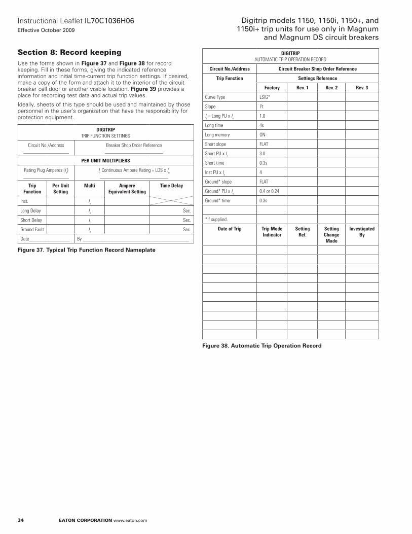
34
Instructional Leaflet IL70C1036H06Effective October 2009
Digitrip models 1150, 1150i, 1150+, and 1150i+ trip units for use only in Magnum
and Magnum DS circuit breakers
eaton corporation www.eaton.com
Section 8: record keepingUse the forms shown in Figure 37 and Figure 38 for record keeping . Fill in these forms, giving the indicated reference information and initial time-current trip function settings . If desired, make a copy of the form and attach it to the interior of the circuit breaker cell door or another visible location . Figure 39 provides a place for recording test data and actual trip values .
Ideally, sheets of this type should be used and maintained by those personnel in the user’s organization that have the responsibility for protection equipment .
DIGITRIP TRIP FUNCTION SETTINGS
Circuit No./Address__________________
Breaker Shop Order Reference_______________________
PER UNIT MULTIPLIERS
Rating Plug Amperes (In)__________________
Ir Continuous Ampere Rating = LDS x In___________________________
Trip Function
Per Unit Setting
Multi Ampere Equivalent Setting
Time Delay
Inst. In
Long Delay In Sec.
Short Delay Ir Sec.
Ground Fault In Sec.
Date________________ By __________________________________________
Figure 37. Typical Trip Function Record Nameplate
DIGITRIP AUTOMATIC TRIP OPERATION RECORD
Circuit No./Address Circuit Breaker Shop Order Reference
Trip Function Settings Reference
Factory Rev. 1 Rev. 2 Rev. 3
Curve Type LSIG*
Slope l2t
lr = Long PU x ln 1.0
Long time 4s
Long memory ON
Short slope FLAT
Short PU x lr 3.0
Short time 0.3s
Inst PU x ln 4
Ground* slope FLAT
Ground* PU x ln 0.4 or 0.24
Ground* time 0.3s
*If supplied.
Date of Trip Trip Mode Indicator
Setting Ref.
Setting Change Made
Investigated By
Figure 38. Automatic Trip Operation Record
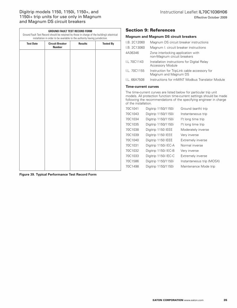
35
Instructional Leaflet IL70C1036H06Effective October 2009
Digitrip models 1150, 1150i, 1150+, and 1150i+ trip units for use only in Magnum and Magnum DS circuit breakers
eaton corporation www.eaton.com
GROUND FAULT TEST RECORD FORMGround Fault Test Record should be retained by those in charge of the building’s electrical
installation in order to be available to the authority having jurisdiction.
Test Date Circuit Breaker Number
Results Tested By
Figure 39. Typical Performance Test Record Form
Section 9: referencesMagnum and Magnum DS circuit breakers
I .B . 2C12060 Magnum DS circuit breaker instructions
I .B . 2C13060 Magnum I . circuit breaker instructions
4a36346 Zone interlocking application with non-Magnum circuit breakers
I .L 70C1143 Installation instructions for Digital Relay accessory Module
I .L . 70C1155 Instruction for TripLink cable accessory for Magnum and Magnum DS
I .L . 66a7508 Instructions for mMInT Modbus Translator Module
Time-current curves
The time-current curves are listed below for particular trip unit models . all protection function time-current settings should be made following the recommendations of the specifying engineer in charge of the installation .
70C1041 Digitrip 1150/1150i Ground (earth) trip
70C1043 Digitrip 1150/1150i Instantaneous trip
70C1034 Digitrip 1150/1150i I2t long time trip
70C1035 Digitrip 1150/1150i I4t long time trip
70C1038 Digitrip 1150 IEEE Moderately inverse
70C1039 Digitrip 1150 IEEE Very inverse
70C1040 Digitrip 1150 IEEE Extremely inverse
70C1031 Digitrip 1150i IEC-a normal inverse
70C1032 Digitrip 1150i IEC-B Very inverse
70C1033 Digitrip 1150i IEC-C Extremely inverse
70C1586 Digitrip 1150/1150i Instantaneous trip (MoSx)
70C1498 Digitrip 1150/1150i Maintenance Mode trip
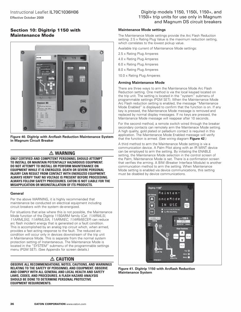
36
Instructional Leaflet IL70C1036H06Effective October 2009
Digitrip models 1150, 1150i, 1150+, and 1150i+ trip units for use only in Magnum
and Magnum DS circuit breakers
eaton corporation www.eaton.com
Section 10: Digitrip 1150 with Maintenance Mode
Figure 40. Digitrip with Arcflash Reduction Maintenance System in Magnum Circuit Breaker
m WARNINGONLY CERTIFIED AND COMPETENT PERSONNEL SHOULD ATTEMPT TO INSTALL OR MAINTAIN POTENTIALLY HAZARDOUS EQUIPMENT. DO NOT ATTEMPT TO INSTALL OR PERFORM MAINTENANCE ON EQUIPMENT WHILE IT IS ENERGIZED. DEATH OR SEVERE PERSONAL INJURY CAN RESULT FROM CONTACT WITH ENERGIZED EQUIPMENT. ALWAYS VERIFY THAT NO VOLTAGE IS PRESENT BEFORE PROCEEDING. ALWAYS FOLLOW SAFETY PROCEDURES. EATON IS NOT LIABLE FOR THE MISAPPLICATION OR MISINSTALLATION OF ITS PRODUCTS.
General
Per the above WaRnInG, it is highly recommended that maintenance be conducted on electrical equipment including circuit breakers with the system de-energized .
For situations that arise where this is not possible, the Maintenance Mode function of the Digitrip 1150aRM family (Cat. 11ARMLSI, 11ARMLSIG, 11ARMLSIA, 11ARMIEC, 11ARMIECEF) can reduce arc flash incident energy that is generated on a fault condition . This is accomplished by an analog trip circuit which, when armed, provides a fast acting response to the fault . The reduced arc condition will occur only in devices downstream of the trip unit in Maintenance Mode . This is separate from the normal system protection setting of Instantaneous . The Maintenance Mode is located in the “SYSTEM” submenu of the programmable settings menu (PGM SET) . (See appendix for screen details .)
m CAUTIONOBSERVE ALL RECOMMENDATIONS, NOTES, CAUTIONS, AND WARNINGS RELATING TO THE SAFETY OF PERSONNEL AND EQUIPMENT. OBSERVE AND COMPLY WITH ALL GENERAL AND LOCAL HEALTH AND SAFETY LAWS, CODES, AND PROCEDURES. A FLASH HAZARD ANALYSIS SHOULD BE DONE TO DETERMINE PERSONAL PROTECTIVE EQUIPMENT REQUIREMENTS.
Maintenance Mode settings
The Maintenance Mode settings provide the arc Flash Reduction setting . 2 .5 x Rating Plug Value is the maximum reduction setting, which correlates to the lowest pickup value .
available trip current of Maintenance Mode settings:
2 .5 x Rating Plug amperes
4 .0 x Rating Plug amperes
6 .0 x Rating Plug amperes
8 .0 x Rating Plug amperes
10 .0 x Rating Plug amperes
Arming Maintenance Mode
There are three ways to arm the Maintenance Mode arc Flash Reduction setting . one method is via the local keypad located on the trip unit . The setting is located in the “system” submenu of programmable settings (PGM SET) . When the Mainternance Mode arc Flash reduction setting is enabled, the message “Maintenance Mode Enabled” is displayed to confirm that the function is on . If any key is pressed, the Maintenance Mode message is removed and replaced by normal display messages . If no keys are pressed, the Maintenance Mode message will reappear after 10 seconds .
For the second method, a remote switch wired through the breaker secondary contacts can remotely arm the Maintenace Mode setting . a high quality, gold plated or palladium contact is required in this application . The Maintenance Mode Enabled message will verify that the function is armed . (See wiring diagram Figure 42 .)
a third method to arm the Maintenance Mode setting is via a communication device . a Palm Pilot along with an IR MInT device can be employed to arm the setting . By initiating the EnaBLE setting, the Maintenance Mode selection in the control screen of the Palm, Maintenance Mode is set . There is a confirmation screen that verifies the arming . a BIM (Breaker Interface Module) is another communcation method to arm the setting . When Maintenance Mode setting is enabled via device communications, this setting must be disabled by device communications .
Figure 41. Digitrip 1150 with Arcflash Reduction Maintenance System

37
Instructional Leaflet IL70C1036H06Effective October 2009
Digitrip models 1150, 1150i, 1150+, and 1150i+ trip units for use only in Magnum and Magnum DS circuit breakers
eaton corporation www.eaton.com
Remote indicator
Circuit breakers built after July 2006 will be wired with secondary contacts a12 which is reassigned to Maintenance Mode Enable (MM_E)—(see label on secondary contacts) . a normally open contact (a10, a11) is available for customer use via programming of Relay a . This contact can be used to indicate remotely that the Maintenance Mode setting is armed . Refer to diagram below for a wiring of this remote (blue light) indicator .
Choosing the reduction setting
The arcflash Reduction Maintenance System switch has five unique settings . From the factory, the Magnum circuit breaker is shipped with the Digitrip unit set to the 2 .5x setting and with its Maintenance Mode disabled . The Maintenance Mode Enabled message provides an indication that the Maintenance Mode setting is armed per one of the three methods described on page 36 .
In general, the selection of one of the Reduction Settings should be determined and selected by a person who is experienced in power system analysis .
This setting choice normally does not change unless there are future system modifications that could increase or decrease fault levels at the circuit breaker location .
For time/current curve information, refer to curve #70C1498 .
Tripping and testing
The Maintenance Mode function will provide fast tripping even when the regular Instantaneous is set to oFF . The Instantaneous LED position is also used to indicate a trip initiated by the Maintenance Mode setting . The Maintenance Mode Trip message will be displayed after a trip .
The Maintenance Mode setting, external wiring (if any), and tripping functionality should all be periodically verified by primary or secondary injection current testing .
Figure 42. Maintenance Mode Wiring Digitrip 1150 with Arcflash Reduction Maintenance System
Control Voltage d
e
LRemote Indicator (BlueLight)
Remote arcflash Reduction Maintenance System Switch g
g
c
a12 B7
alternate Customer Wiring
(partial)
ab
c
a12 B7a14a15 a11a10 B2B1
Communication wiring to IR MInT, BIM, MoDBUS MInT or Powernet computer . This can activate Maintenance Mode if desired .
arcflash Reduction Maintenance System Switch
a f
Magnum Breaker (with MM wiring)
a The Digitrip 1150 (Cat. #11ARMxxx) can locally be placed in Maintenance Mode via front panel programming of the trip unit. The function can also be armed via a remote switch as shown. In addition, the function can be activated via communications. The display will indicate “Maintenance Mode in Use” when in this special mode.
b The recommended selector switch for this low voltage application is Eaton part number 10250T1333-2E, which includes a contact block rated for logic level and corrosive use.c The maximum length of this wiring to the remote Arcflash Reduction Maintenance System switch (or alternate relay contact) is 9.78 feet (3m). Use #20 AWG wire or larger.d Control voltage is 120 Vac or 230 Vac or 24–48 Vdc or 125 Vdc as ordered. Check Magnum circuit breaker front cover for trip unit power requirements.e A remote stack light, annunciator panel or other remote indication device can be connected to remotely verify that the Digitrip is in Maintenance Mode.f Relay A contact changes state when Digitrip is in Maintenance Mode. This action requires pre-assigning Relay A to Maintenance Mode function. Relay C contacts (A9, A10) are also available to
be programmed to provide an indication of a trip in Maintenance Mode. Contact is rated 1A at 120 Vac or 0.5A at 230 Vac or 1A at 24–48 Vdc or 0.35A at 125 Vdc.g The Digitrip 1150 can also be placed remotely in its Maintenance Mode via a general purpose relay (ice cube type with logic level contacts) activated by a remote control switch. A recommended
type is IDEC Relay Ry22. Choose voltage as desired.
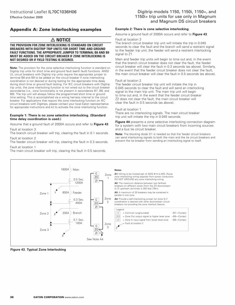
38
Instructional Leaflet IL70C1036H06Effective October 2009
Digitrip models 1150, 1150i, 1150+, and 1150i+ trip units for use only in Magnum
and Magnum DS circuit breakers
eaton corporation www.eaton.com
appendix a: Zone interlocking examples
m NOTICETHE PROVISION FOR ZONE INTERLOCkING IS STANDARD ON CIRCUIT BREAkERS WITH DIGITRIP TRIP UNITS FOR SHORT TIME AND GROUND FAULT FUNCTIONS. THE APPROPRIATE JUMPER TO TERMINAL B8 AND B9 MUST BE ADDED ON THE CIRCUIT BREAkER IF ZONE INTERLOCkING IS NOT DESIRED OR IF FIELD TESTING IS DESIRED.
otee:N The provision for the zone selective interlocking function is standard on Digitrip trip units for short time and ground fault (earth fault) functions . anSI/UL circuit breakers with Digitrip trip units require the appropriate jumper to terminal B8 and B9 to be added on the circuit breaker if zone interlocking coordination is not desired or during testing for the appropriate time delay during short time or ground fault testing . For IEC circuit breakers with Digitrip trip units, the zone interlocking function is not wired out to the circuit breaker secondaries (i .e ., zone functionality is not present in secondaries B7, B8, and B9) . The trip unit will always follow the programmed short time or ground time setting . This is accomplished via a wiring harness internal to the circuit breaker . For applications that require the zone interlocking function on IEC circuit breakers with Digitrips, please contact your local Eaton representative for appropriate instructions and kit to activate the zone interlocking function .
Example 1e: There is no zone selective interlocking. (Standard time delay coordination is used.)
assume that a ground fault of 2000a occurs and refer to Figure 43 .
Fault at location 3 The branch circuit breaker will trip, clearing the fault in 0 .1 seconds .
Fault at location 2 The feeder circuit breaker will trip, clearing the fault in 0 .3 seconds .
Fault at location 1 The main circuit breaker will trip, clearing the fault in 0 .5 seconds .
Example 2e: There is zone selective interlocking.
assume a ground fault of 2000a occurs and refer to Figure 43 .
Fault at location 3 The branch circuit breaker trip unit will initiate the trip in 0 .045 seconds to clear the fault and the branch will send a restraint signal to the feeder trip unit; the feeder will send a restraint interlocking signal to Z1 .
Main and feeder trip units will begin to time out and, in the event that the branch circuit breaker does not clear the fault, the feeder circuit breaker will clear the fault in 0 .3 seconds (as above) . Similarly, in the event that the feeder circuit breaker does not clear the fault, the main circuit breaker will clear the fault in 0 .5 seconds (as above) .
Fault at location 2 The feeder circuit breaker trip unit will initiate the trip in 0 .045 seconds to clear the fault and will send an interlocking signal to the main trip unit . The main trip unit will begin to time out and, in the event that the feeder circuit breaker Z2 does not clear the fault, the main circuit breaker will clear the fault in 0 .5 seconds (as above) .
Fault at location 1 There are no interlocking signals . The main circuit breaker trip unit will initiate the trip in 0 .045 seconds .
Figure 44 presents a zone selective interlocking connection diagram for a system with two main circuit breakers from incoming sources and a bus tie circuit breaker .
otee:N The blocking diode D1 is needed so that the feeder circuit breakers can send interlocking signals to both the main and the tie circuit breakers and prevent the tie breaker from sending an interlocking signal to itself .
Figure 43. Typical Zone Interlocking
2
1
3
C
C
CZO
ZO
ZO
ZI
ZI
ZI
1600a Main
800a
200a
Feeder
Branch
Zone 1
Zone 2
Zone 3
0 .1 Sec . 100a
0 .3 Sec . 400a
0 .5 Sec . 1200a
Zone 1
Zone 2
Zone 3
See note a4
C = Common (ungrounded) –B7—Contact Zo = Zone out output signal to higher level zone –B9—Contact ZI = Zone In input signal from lower level zone –B8—Contact = Fault at location 2
Notese:
A1e: Wiring to be twisted pair of aWG #14 to #20 . Route zone interlocking wiring separate from power conductors . Do noT GRoUnD any zone interlocking wiring .
A2e: The maximum distance between two farthest breakers on different zones (from the Zo downstream to ZI upstream terminals is 250 feet (76m) .
A3e: a maximum of 20 breakers may be contained in parallel in one zone .
A4e: Provide a self-interlocking jumper (on Zone 3) if coordination is desired with other downstream circuit breakers not providing the zone interlock feature .
2
Legend
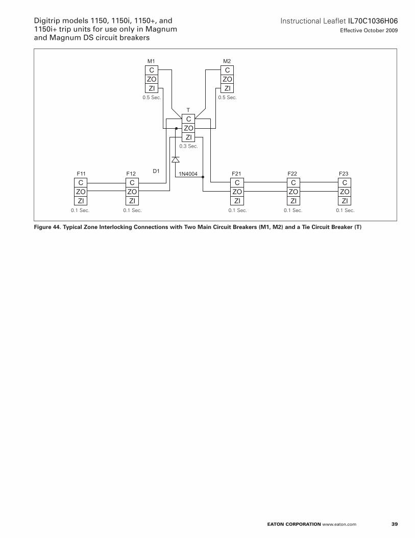
39
Instructional Leaflet IL70C1036H06Effective October 2009
Digitrip models 1150, 1150i, 1150+, and 1150i+ trip units for use only in Magnum and Magnum DS circuit breakers
eaton corporation www.eaton.com
Figure 44. Typical Zone Interlocking Connections with Two Main Circuit Breakers (M1, M2) and a Tie Circuit Breaker (T)
F23
CZOZI
F22
CZOZI
T
CZOZI
F21
CZOZI
F12 1N4004D1
CZOZI
M2
CZOZI
M1
CZOZI
F11
CZOZI
0 .5 Sec . 0 .5 Sec .
0 .3 Sec .
0 .1 Sec . 0 .1 Sec . 0 .1 Sec . 0 .1 Sec . 0 .1 Sec .
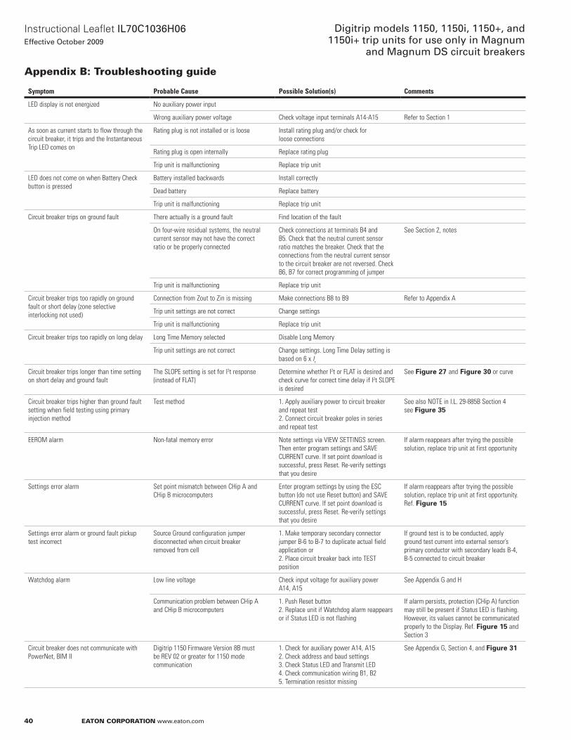
40
Instructional Leaflet IL70C1036H06Effective October 2009
Digitrip models 1150, 1150i, 1150+, and 1150i+ trip units for use only in Magnum
and Magnum DS circuit breakers
eaton corporation www.eaton.com
appendix B: troubleshooting guide
Symptom Probable Cause Possible Solution(s) Comments
LED display is not energized No auxiliary power input
Wrong auxiliary power voltage Check voltage input terminals A14-A15 Refer to Section 1
As soon as current starts to flow through the circuit breaker, it trips and the Instantaneous Trip LED comes on
Rating plug is not installed or is loose Install rating plug and/or check for loose connections
Rating plug is open internally Replace rating plug
Trip unit is malfunctioning Replace trip unit
LED does not come on when Battery Check button is pressed
Battery installed backwards Install correctly
Dead battery Replace battery
Trip unit is malfunctioning Replace trip unit
Circuit breaker trips on ground fault There actually is a ground fault Find location of the fault
On four-wire residual systems, the neutral current sensor may not have the correct ratio or be properly connected
Check connections at terminals B4 and B5. Check that the neutral current sensor ratio matches the breaker. Check that the connections from the neutral current sensor to the circuit breaker are not reversed. Check B6, B7 for correct programming of jumper
See Section 2, notes
Trip unit is malfunctioning Replace trip unit
Circuit breaker trips too rapidly on ground fault or short delay (zone selective interlocking not used)
Connection from Zout to Zin is missing Make connections B8 to B9 Refer to Appendix A
Trip unit settings are not correct Change settings
Trip unit is malfunctioning Replace trip unit
Circuit breaker trips too rapidly on long delay Long Time Memory selected Disable Long Memory
Trip unit settings are not correct Change settings. Long Time Delay setting is based on 6 x Ir
Circuit breaker trips longer than time setting on short delay and ground fault
The SLOPE setting is set for I2t response (instead of FLAT)
Determine whether I2t or FLAT is desired and check curve for correct time delay if I2t SLOPE is desired
See Figure 27 and Figure 30 or curve
Circuit breaker trips higher than ground fault setting when field testing using primary injection method
Test method 1. Apply auxiliary power to circuit breaker and repeat test2. Connect circuit breaker poles in series and repeat test
See also NOTE in I.L. 29-885B Section 4see Figure 35
EEROM alarm Non-fatal memory error Note settings via VIEW SETTINGS screen. Then enter program settings and SAVE CURRENT curve. If set point download is successful, press Reset. Re-verify settings that you desire
If alarm reappears after trying the possible solution, replace trip unit at first opportunity
Settings error alarm Set point mismatch between CHip A and CHip B microcomputers
Enter program settings by using the ESC button (do not use Reset button) and SAVE CURRENT curve. If set point download is successful, press Reset. Re-verify settings that you desire
If alarm reappears after trying the possible solution, replace trip unit at first opportunity. Ref. Figure 15
Settings error alarm or ground fault pickup test incorrect
Source Ground configuration jumper disconnected when circuit breaker removed from cell
1. Make temporary secondary connector jumper B-6 to B-7 to duplicate actual field application or2. Place circuit breaker back into TEST position
If ground test is to be conducted, apply ground test current into external sensor’s primary conductor with secondary leads B-4, B-5 connected to circuit breaker
Watchdog alarm Low line voltage Check input voltage for auxiliary power A14, A15
See Appendix G and H
Communication problem between CHip A and CHip B microcomputers
1. Push Reset button2. Replace unit if Watchdog alarm reappears or if Status LED is not flashing
If alarm persists, protection (CHip A) function may still be present if Status LED is flashing. However, its values cannot be communicated properly to the Display. Ref. Figure 15 and Section 3
Circuit breaker does not communicate with PowerNet, BIM II
Digitrip 1150 Firmware Version 8B must be REV 02 or greater for 1150 mode communication
1. Check for auxiliary power A14, A152. Check address and baud settings3. Check Status LED and Transmit LED4. Check communication wiring B1, B25. Termination resistor missing
See Appendix G, Section 4, and Figure 31
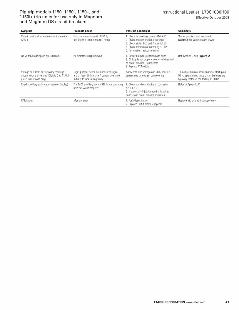
41
Instructional Leaflet IL70C1036H06Effective October 2009
Digitrip models 1150, 1150i, 1150+, and 1150i+ trip units for use only in Magnum and Magnum DS circuit breakers
eaton corporation www.eaton.com
Symptom Probable Cause Possible Solution(s) Comments
Circuit breaker does not communicate with AEM II
For communication with AEM II, use Digitrip 1150 in the 910 mode
1. Check for auxiliary power A14, A152. Check address and baud settings3. Check Status LED and Transmit LED4. Check communication wiring B1, B25. Termination resistor missing
See Appendix G and Section 4Note: OK for Version 6 and lower
No voltage readings in METER menu PT dielectric plug removed 1. Circuit breaker is backfed and open 2. Digitrip is not properly connected/inserted to circuit breaker I1 connector3. Replace PT Module
Ref. Section 3 and Figure 2
Voltage or current or frequency readings appear wrong or varying (Digitrip Cat. 11xxx pre-2003 versions only)
Digitrip meter needs both phase voltages and at least 20% phase A current available initially to lock in frequency
Apply both line voltage and 20% phase A current one time to set up metering
This situation may occur on initial startup on 50 Hz applications since circuit breakers are typically tested in the factory at 60 Hz
Check auxiliary switch (message on display) The MCR auxiliary switch 52b is not operating or is not wired properly
1. Check switch continuity on connector K2-1, K2-22. If secondary injection testing is being done, close circuit breaker and retest
Refer to Appendix C
RAM alarm Memory error 1. Push Reset button2. Replace unit if alarm reappears
Replace trip unit at first opportunity
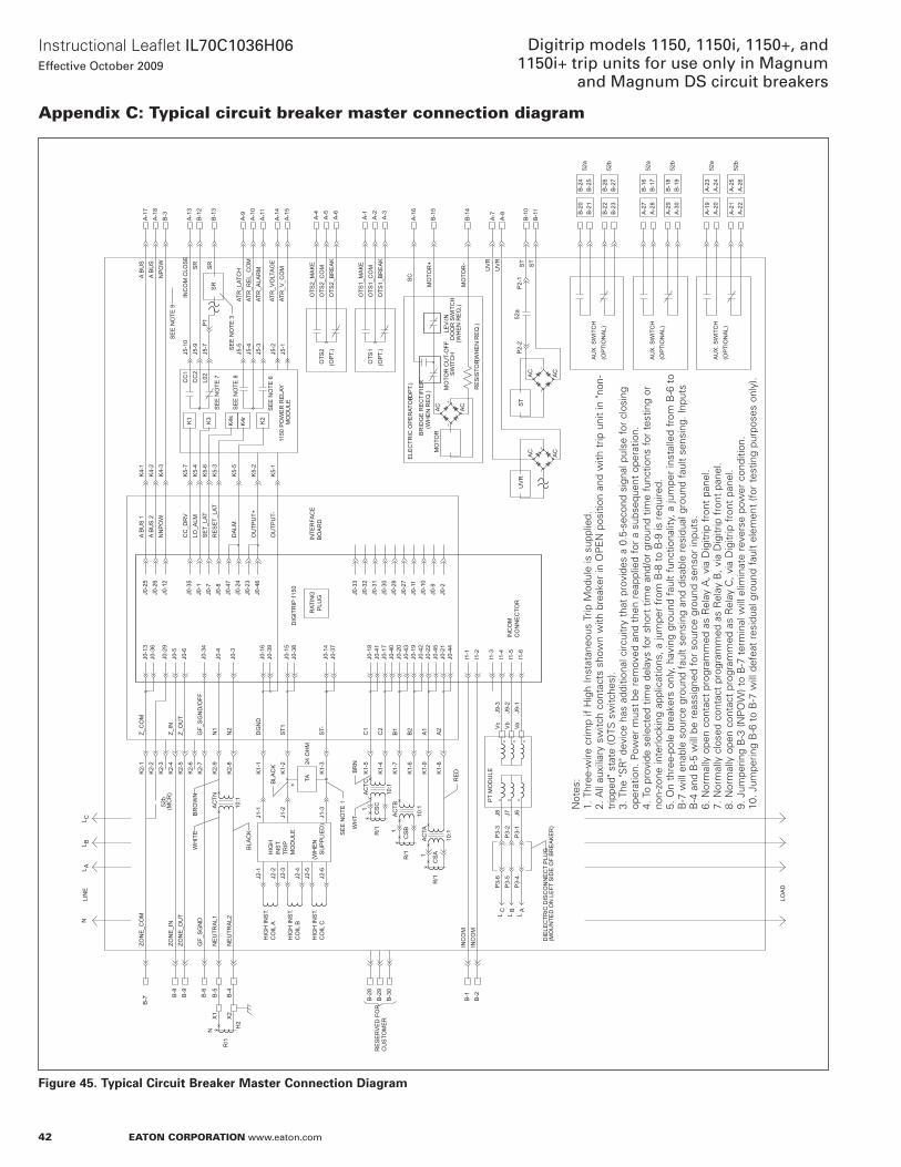
42
Instructional Leaflet IL70C1036H06Effective October 2009
Digitrip models 1150, 1150i, 1150+, and 1150i+ trip units for use only in Magnum
and Magnum DS circuit breakers
eaton corporation www.eaton.com
appendix c: typical circuit breaker master connection diagram
Figure 45. Typical Circuit Breaker Master Connection Diagram
AC
AC
AC
AC
AC
AC
K2-
1K
2-2
K2-
3K
2-4
K2-
5K
2-6
K2-
7
K2-
9
K2-
8
Z_C
OM
Z_IN
Z_O
UT
GF_
SG
ND
/OFF
N1
N2
J5-1
0J5
-9J5
-7
1150
PO
WE
R R
ELA
YM
OD
ULE
A-1
3B
-12
B-1
3
A-7
UV
R
B-1
1
A-8
ST
B-1
0
B-1
4
B-1
5
SC
A-6
A-5
A-4
A-1
7
SR
A-1
8
RAT
ING
PLU
G
DIG
ITR
IP 1
150
DG
ND
K1-
1
ST1
K1-
2
ST-
K1-
3
C1
K1-
5
C2
K1-
4
B1
K1-
7
B2
K1-
6
A1
K1-
9
A2
K1-
8
HIG
HIN
ST.
TRIP
MO
DU
LE
(WH
EN
HIG
H IN
ST.
CO
IL A
CO
IL B
HIG
H IN
ST.
HIG
H IN
ST.
CO
IL C
R/1
CS
C
CS
BR
/1
R/1
CS
A
1
B-8
B-7 B
-9
B-6
R/1
NE
UTR
AL1
NE
UTR
AL2
B-5
B-4
AU
X. S
WIT
CH
(OP
TIO
NA
L)
L ABL
L CN
SU
PP
LIE
D)
J0-1
3J0
-36
J0-6
J0-5
J0-3
4
J0-4
J0-3
24 O
HM
TA
J0-1
6J0
-39
J0-3
8J0
-15
J0-1
4J0
-37
J0-4
1J0
-18
J0-1
7J0
-40
J0-4
3J0
-20
J0-1
9J0
-42
J0-4
5J0
-22
J0-2
1J0
-44
I1-1
I1-2
B-1
B-2
INC
OM
INC
OM
I1-3
I1-4
I1-6
I1-5
LC B
L LA
52b
(MC
R)
J0-2
5J0
-26
J0-1
2J0
-29
NN
PO
WA
BU
S 2
A B
US
1
B-3
K4-
3K
4-2
K4-
1
J5-5
A-9
J5-4
J5-3
J5-2
J5-1
A-1
0
A-1
4A
-15
(OP
T.)
J0-8
J0-7
J0-1
J0-3
5
J0-4
7
SE
T_LA
T
K5-
7
K5-
6K
5-3
K5-
5
RE
SE
T_LA
T
J0-2
4
K5-
1
DA
LM
K5-
4LO
_ALM
J0-2
3K
5-2
J0-4
6
CC
_DR
V
INTE
RFA
CE
BO
AR
D
INC
OM
CO
NN
EC
TOR
J0-3
2J0
-33
J0-3
1J0
-30
J0-1
0J0
-11
J0-2
8J0
-27
J0-9
J0-2
MO
TOR
ELE
CTR
IC O
PE
RAT
OR
(OP
TIO
NA
L)A
UX
. SW
ITC
H
J2-1
J2-2
J2-3
J2-4
J2-5
J2-6
J1-1
J1-2
J1-3
N
Vc
Vb
Va
1
1
10:1
10:1
10:1
AC
TC
AC
TB
AC
TA
AC
TN
10:1
BR
OW
N
LIN
E
LOA
D
GF_
SG
ND
ZON
E_O
UT
ZON
E_I
N
ZON
E_C
OM
WH
ITE
(OP
T.)
OTS
1_B
RE
AK
OTS
1_M
AK
EA
-1A
-2A
-3
OTS
1
OTS
2
BR
NW
HT
RE
D
PT
MO
DU
LE
+BLA
CK
SE
E N
OTE
1
OTS
1_C
OM
OTS
2_B
RE
AK
OTS
2_C
OM
OTS
2_M
AK
E
B-1
9B
-18
A-2
9A
-30
52a
52b
52b
52a
A-2
8A
-27
B-1
6B
-17
B-2
1B
-20
B-2
4B
-25
UV
RU
VR
B-2
9B
-28
B-3
0
RE
SE
RV
ED
FO
R
B-2
3B
-22
B-2
7B
-26
BLA
CK
A-2
4A
-23
A-1
9A
-20
52b
52a
A-2
2A
-21
A-2
5A
-26
AU
X. S
WIT
CH
(OP
TIO
NA
L)
MO
TOR
-
MO
TOR
+
NP
OW
A B
US
A B
US
OU
TPU
T+
OU
TPU
T-
SR
SR
A-1
1
INC
OM
CLO
SE
ATR
_LAT
CH
ATR
_RE
L_C
OM
ATR
_ALA
RM
ATR
_VO
LTA
GE
ATR
_V_C
OM
K1
K4s
K4rK3
K2
ST
ST
P2-
252
aP
2-1
A-1
6
(WH
EN
RE
Q.)
CC
1C
C2
L02
P1
SE
E N
OTE
3
DIE
LEC
TRIC
DIS
CO
NN
EC
T P
LUG
(MO
UN
TED
ON
LE
FT S
IDE
OF
BR
EA
KE
R)
J9-3
J9-2
J9-1
J8 J7 J6
P3-
3P
3-2
P3-
1
P3-
6P
3-5
P3-
4
H2
X2
X1
CU
STO
ME
R
SE
E N
OTE
7
SE
E N
OTE
8
SE
E N
OTE
6
MO
TOR
CU
T-O
FFS
WIT
CH
LEV-
IND
OO
R S
WIT
CH
(WH
EN
RE
Q.)
RE
SIS
TOR
BR
IDG
E R
EC
TIFI
ER
(WH
EN
RE
Q.)
(OP
T.)
SE
E N
OTE
9
not
es:
1 . T
hree
-wire
crim
p if
Hig
h In
stat
aneo
us T
rip M
odul
e is
sup
plie
d .2 .
all
auxi
liary
sw
itch
cont
acts
sho
wn
with
bre
aker
in o
PE
n p
ositi
on a
nd w
ith t
rip u
nit
in "n
on-
trip
ped"
sta
te (o
TS s
witc
hes)
.3 .
The
"SR
" dev
ice
has
addi
tiona
l circ
uitr
y th
at p
rovi
des
a 0 .
5-se
cond
sig
nal p
ulse
for
clo
sing
op
erat
ion .
Pow
er m
ust
be r
emov
ed a
nd t
hen
reap
plie
d fo
r a
subs
eque
nt o
pera
tion .
4 . T
o pr
ovid
e se
lect
ed t
ime
dela
ys f
or s
hort
tim
e an
d/or
gro
und
time
func
tions
for
tes
ting
or
non-
zone
inte
rlock
ing
appl
icat
ions
, a ju
mpe
r fr
om B
-8 t
o B
-9 is
req
uire
d .5 .
on
thre
e-po
le b
reak
ers
only
, hav
ing
grou
nd f
ault
func
tiona
lity,
a ju
mpe
r in
stal
led
from
B-6
to
B-7
will
ena
ble
sour
ce g
roun
d fa
ult
sens
ing
and
disa
ble
resi
dual
gro
und
faul
t se
nsin
g . In
puts
B
-4 a
nd B
-5 w
ill b
e re
assi
gned
for
sou
rce
grou
nd s
enso
r in
puts
.6 .
nor
mal
ly o
pen
cont
act
prog
ram
med
as
Rel
ay a
, via
Dig
itrip
fro
nt p
anel
.7 .
nor
mal
ly c
lose
d co
ntac
t pr
ogra
mm
ed a
s R
elay
B, v
ia D
igitr
ip f
ront
pan
el .
8 . n
orm
ally
ope
n co
ntac
t pr
ogra
mm
ed a
s R
elay
C, v
ia D
igitr
ip f
ront
pan
el .
9 . J
umpe
ring
B-3
(nP
oW
) to
B-7
ter
min
al w
ill e
limin
ate
reve
rse
pow
er c
ondi
tion .
10 . J
umpe
ring
B-6
to
B-7
will
def
eat
resi
dual
gro
und
faul
t el
emen
t (f
or t
estin
g pu
rpos
es o
nly)
.
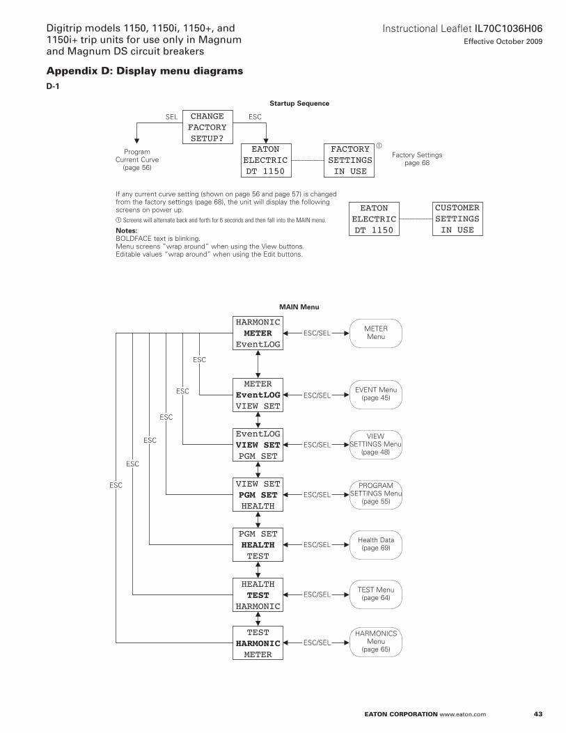
43
Instructional Leaflet IL70C1036H06Effective October 2009
Digitrip models 1150, 1150i, 1150+, and 1150i+ trip units for use only in Magnum and Magnum DS circuit breakers
eaton corporation www.eaton.com
appendix D: Display menu diagramsD-1
EATONELECTRICDT 1150
EATONELECTRICDT 1150
FACTORYSETTINGSIN USE
CUSTOMERSETTINGSIN USE
CHANGEFACTORYSETUP?
HARMONICMETER
EventLOG
METEREventLOGVIEW SET
EventLOGVIEW SETPGM SET
VIEW SETPGM SETHEALTH
PGM SETHEALTHTEST
HEALTHTEST
HARMONIC
TESTHARMONICMETER
Startup Sequence
SEL ESC
a
Factory Settings page 68
Program Current Curve
(page 56)
METER Menu
If any current curve setting (shown on page 56 and page 57) is changed from the factory settings (page 68), the unit will display the following screens on power up .a Screens will alternate back and forth for 6 seconds and then fall into the MAIN menu.
otese:N BoLDFaCE text is blinking . Menu screens “wrap around” when using the View buttons . Editable values “wrap around” when using the Edit buttons .
MAIN Menu
ESC
ESC
ESC
ESC
ESC
ESC
ESC/SEL
ESC/SEL
ESC/SEL
ESC/SEL
ESC/SEL
ESC/SEL
ESC/SEL
EVEnT Menu(page 45)
VIEWSETTInGS Menu
(page 48)
PRoGRaM SETTInGS Menu
(page 55)
Health Data (page 69)
TEST Menu(page 64)
HaRMonICS Menu
(page 65)
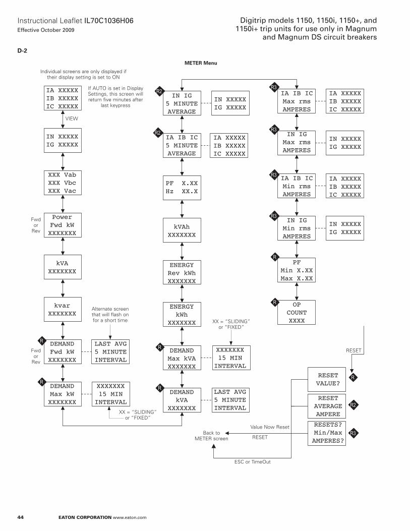
44
Instructional Leaflet IL70C1036H06Effective October 2009
Digitrip models 1150, 1150i, 1150+, and 1150i+ trip units for use only in Magnum
and Magnum DS circuit breakers
eaton corporation www.eaton.com
D-2
OPCOUNTXXXX
PFMin X.XXMax X.XX
IA IB ICMax rmsAMPERES
IA XXXXXIB XXXXXIC XXXXX
IN IGMax rmsAMPERES
IN XXXXXIG XXXXX
IA IB ICMin rmsAMPERES
IA XXXXXIB XXXXXIC XXXXX
IN IGMin rmsAMPERES
IN XXXXXIG XXXXX
kVAhXXXXXXX
PF X.XXHz XX.X
ENERGYRev kWhXXXXXXX
ENERGYkWh
XXXXXXX
LAST AVG5 MINUTEINTERVAL
DEMANDkVA
XXXXXXX
DEMANDMax kVAXXXXXXX
XXXXXXX15 MININTERVAL
IA IB IC5 MINUTEAVERAGE
IA XXXXXIB XXXXXIC XXXXX
IN IG5 MINUTEAVERAGE
IN XXXXXIG XXXXX
IN XXXXXIG XXXXX
XXX VabXXX VbcXXX Vac
PowerFwd kWXXXXXXX
kVAXXXXXXX
kvarXXXXXXX
IA XXXXXIB XXXXXIC XXXXX
DEMANDMax kWXXXXXXX
DEMANDFwd kWXXXXXXX
LAST AVG5 MINUTEINTERVAL
RESETVALUE?
R
R
R
R
RXXXXXXX15 MININTERVAL
RESETS?Min/MaxAMPERES?
2R2
R
R
2R3
RESETAVERAGEAMPERE
2R2
2R3
2R3
2R3
2R3
2R2
METER Menu
Individual screens are only displayed if their display setting is set to on
If aUTo is set in Display Settings, this screen will return five minutes after
last keypress
VIEW
Fwd or
Rev
Fwd or
Rev
alternate screen that will flash on for a short time
xx = “SLIDInG” or “FIxED”
xx = “SLIDInG” or “FIxED”
Back to METER screen
ESC or Timeout
Value now Reset
RESET
RESET
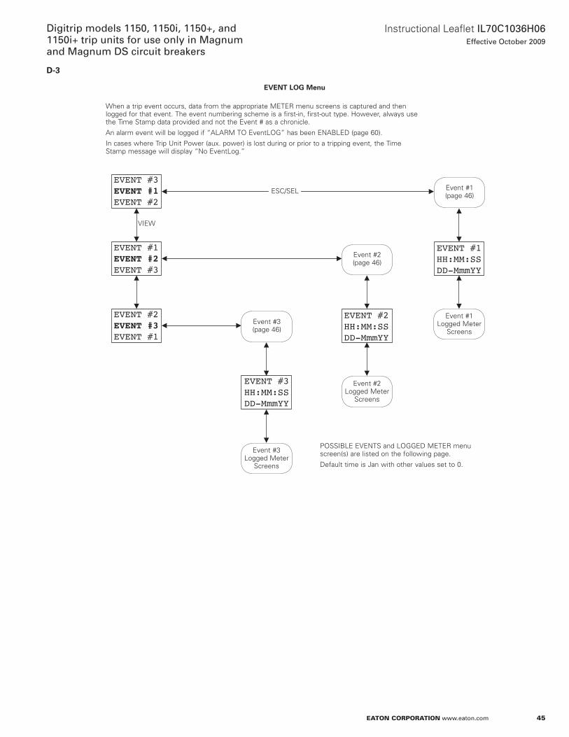
45
Instructional Leaflet IL70C1036H06Effective October 2009
Digitrip models 1150, 1150i, 1150+, and 1150i+ trip units for use only in Magnum and Magnum DS circuit breakers
eaton corporation www.eaton.com
D-3
EVENT #2EVENT #3EVENT #1
EVENT #3EVENT #1EVENT #2
EVENT #1EVENT #2EVENT #3
EVENT #3HH:MM:SSDD-MmmYY
EVENT #1HH:MM:SSDD-MmmYY
EVENT #2HH:MM:SSDD-MmmYY
EVENT LOG Menu
When a trip event occurs, data from the appropriate METER menu screens is captured and then logged for that event . The event numbering scheme is a first-in, first-out type . However, always use the Time Stamp data provided and not the Event # as a chronicle .
an alarm event will be logged if “aLaRM To EventLoG” has been EnaBLED (page 60) .
In cases where Trip Unit Power (aux . power) is lost during or prior to a tripping event, the Time Stamp message will display “no EventLog .”
PoSSIBLE EVEnTS and LoGGED METER menu screen(s) are listed on the following page .
Default time is Jan with other values set to 0 .
Event #1 (page 46)
VIEW
ESC/SEL
Event #2 (page 46)
Event #3 (page 46)
Event #3 Logged Meter
Screens
Event #2 Logged Meter
Screens
Event #1 Logged Meter
Screens
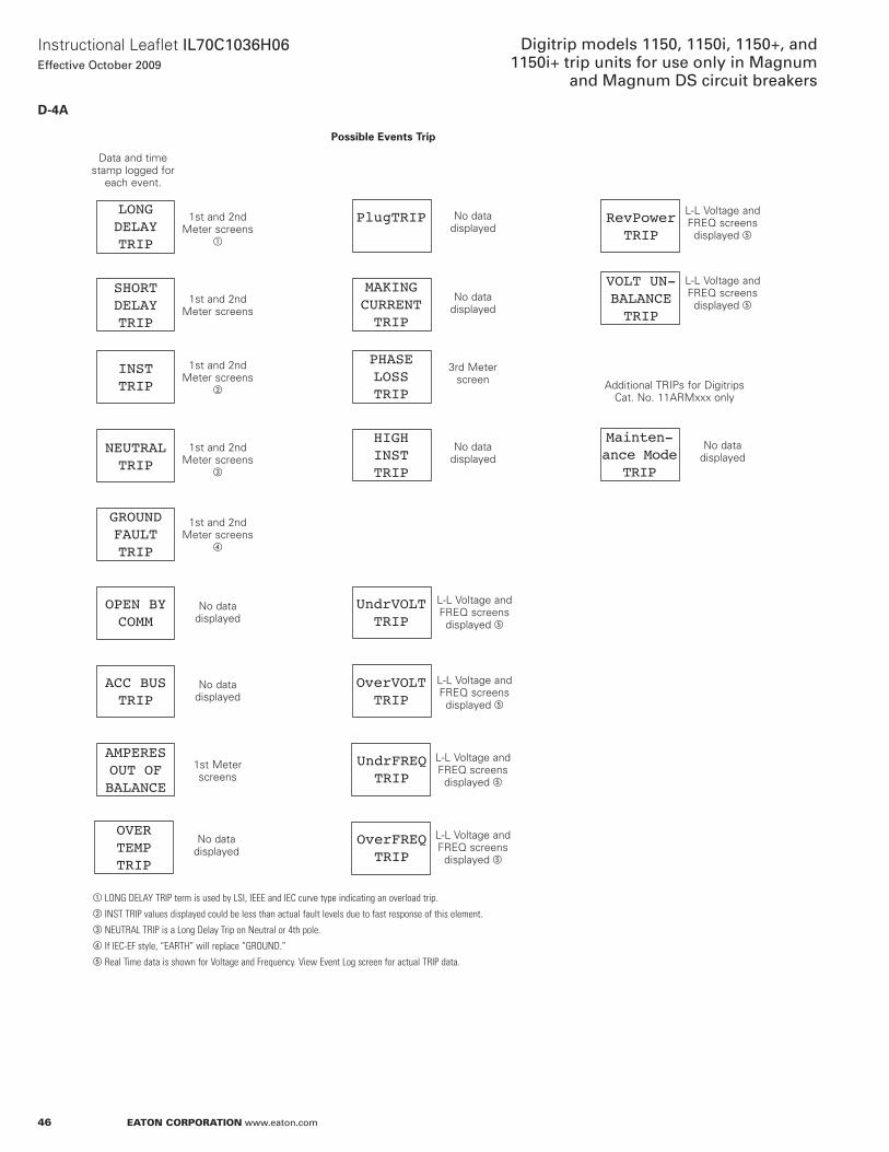
46
Instructional Leaflet IL70C1036H06Effective October 2009
Digitrip models 1150, 1150i, 1150+, and 1150i+ trip units for use only in Magnum
and Magnum DS circuit breakers
eaton corporation www.eaton.com
D-4A
LONGDELAYTRIP
SHORTDELAYTRIP
INSTTRIP
GROUNDFAULTTRIP
OverVOLTTRIP
PHASELOSSTRIP
MAKINGCURRENTTRIP
OPEN BYCOMM
ACC BUSTRIP
AMPERESOUT OFBALANCE
VOLT UN-BALANCETRIP
Mainten-ance Mode
TRIP
PlugTRIP
UndrVOLTTRIP
RevPowerTRIP
NEUTRALTRIP
HIGHINSTTRIP
OVERTEMPTRIP
UndrFREQTRIP
OverFREQTRIP
Possible Events Trip
a LONG DELAY TRIP term is used by LSI, IEEE and IEC curve type indicating an overload trip.b INST TRIP values displayed could be less than actual fault levels due to fast response of this element.c NEUTRAL TRIP is a Long Delay Trip on Neutral or 4th pole.d If IEC-EF style, “EARTH” will replace “GROUND.”e Real Time data is shown for Voltage and Frequency. View Event Log screen for actual TRIP data.
Data and time stamp logged for
each event .
1st and 2nd Meter screens
a
1st and 2nd Meter screens
1st and 2nd Meter screens
b
1st and 2nd Meter screens
c
1st and 2nd Meter screens
d
no data displayed
no data displayed
1st Meter screens
no data displayed
no data displayed
3rd Meter screen
no data displayed
additional TRIPs for Digitrips Cat . no . 11aRMxxx only
L-L Voltage and FREQ screens
displayed e
L-L Voltage and FREQ screens
displayed e
L-L Voltage and FREQ screens
displayed e
L-L Voltage and FREQ screens
displayed e
L-L Voltage and FREQ screens
displayed e
L-L Voltage and FREQ screens
displayed e
no data displayed
no data displayed
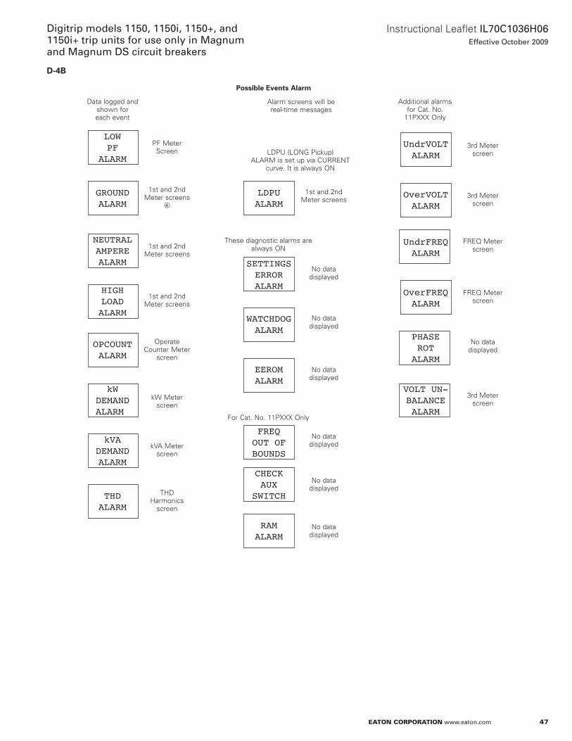
47
Instructional Leaflet IL70C1036H06Effective October 2009
Digitrip models 1150, 1150i, 1150+, and 1150i+ trip units for use only in Magnum and Magnum DS circuit breakers
eaton corporation www.eaton.com
D-4B
GROUNDALARM
LOWPF
ALARM
NEUTRALAMPEREALARM
HIGHLOADALARM
OPCOUNTALARM
kWDEMANDALARM
kVADEMANDALARM
THDALARM
UndrVOLTALARM
OverVOLTALARM
UndrFREQALARM
OverFREQALARM
PHASEROTALARM
VOLT UN-BALANCEALARM
LDPUALARM
SETTINGSERRORALARM
WATCHDOGALARM
EEROMALARM
FREQOUT OFBOUNDS
CHECKAUX
SWITCH
RAMALARM
Possible Events Alarm
Data logged and shown for each event
PF Meter Screen
1st and 2nd Meter screens
d
1st and 2nd Meter screens
1st and 2nd Meter screens
operate Counter Meter
screen
kW Meter screen
kVa Meter screen
THD Harmonics
screen
LDPU (LonG Pickup) aLaRM is set up via CURREnT
curve . It is always on
1st and 2nd Meter screens
no data displayed
no data displayed
For Cat . no . 11Pxxx only
no data displayed
no data displayed
3rd Meter screen
3rd Meter screen
FREQ Meter screen
FREQ Meter screen
alarm screens will be real-time messages
3rd Meter screen
no data displayed
no data displayed
no data displayed
These diagnostic alarms are always on
additional alarms for Cat . no .
11Pxxx only
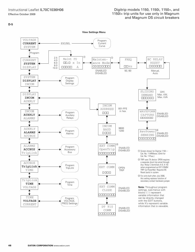
48
Instructional Leaflet IL70C1036H06Effective October 2009
Digitrip models 1150, 1150i, 1150+, and 1150i+ trip units for use only in Magnum
and Magnum DS circuit breakers
eaton corporation www.eaton.com
D-5
VOLTAGECURRENTSYSTEM
Hz. x In
A
CURRENTSYSTEMDISPLAY
SYSTEMDISPLAYINCOM
DISPLAYINCOMAUXRLY
INCOMAUXRLYALARMS
AUXRLYALARMSACCBUS
ALARMSACCBUSTripLink
ACCBUSTripLinkTIME
TripLinkTIME
VOLTAGE
TIMEVOLTAGECURRENT
Maint PU Mainten-ance Mode
FREQ BC RELAYRESET
SLIDINGDEMAND
WAVEFORMCAPTURE
RevPowerSENSING
INCOMADDRESS
INCOMBAUD
EXT COMMOpenTrip
EXT COMM
EXT COMMCLOSE
DT 910COMM
View Settings Menu
ESC/SEL
Program
Program Current Curve
Program Display Settings
Program auxiliary Relays
Program alarms
Program accessory
Bus
Program VoLTaGE,
FREQ Settings
EnaBLED DISaBLED
a Screen shown for Digitrip 1150—Cat. No. 11ARMxxxx. (Omit for Cat. No. 11Pxxx.)
b TRIP uses TA device. OPEN requires a separate shunt trip wired through Aux. Relay C (terminals A-9, A-10) when programmed as ExT COMM TRIP via PowerNet. Requires BC Reset (auto) in system.
c For units built after July 2006, this setting replaces function of secondary contact hardware jumper.
Program TripLink
Program Time
otee:N Throughout program settings, sub-menus with blocks ( ) represent variable information that can be directly changed with the EDIT buttons, while x’s represent variable information that is viewable .
EnaBLED DISaBLED
oPEn TRIP
EnaBLED DISaBLED
9600 1200
001-FFE in hex
EnaBLED DISaBLED
EnaBLED DISaBLED
oFF, Max . kW, Max . kVa
Manual, auto
50, 60EnaBLED DISaBLED
2 .5 4 .0 6 .0 8 .0
10 .0
a a
b
c
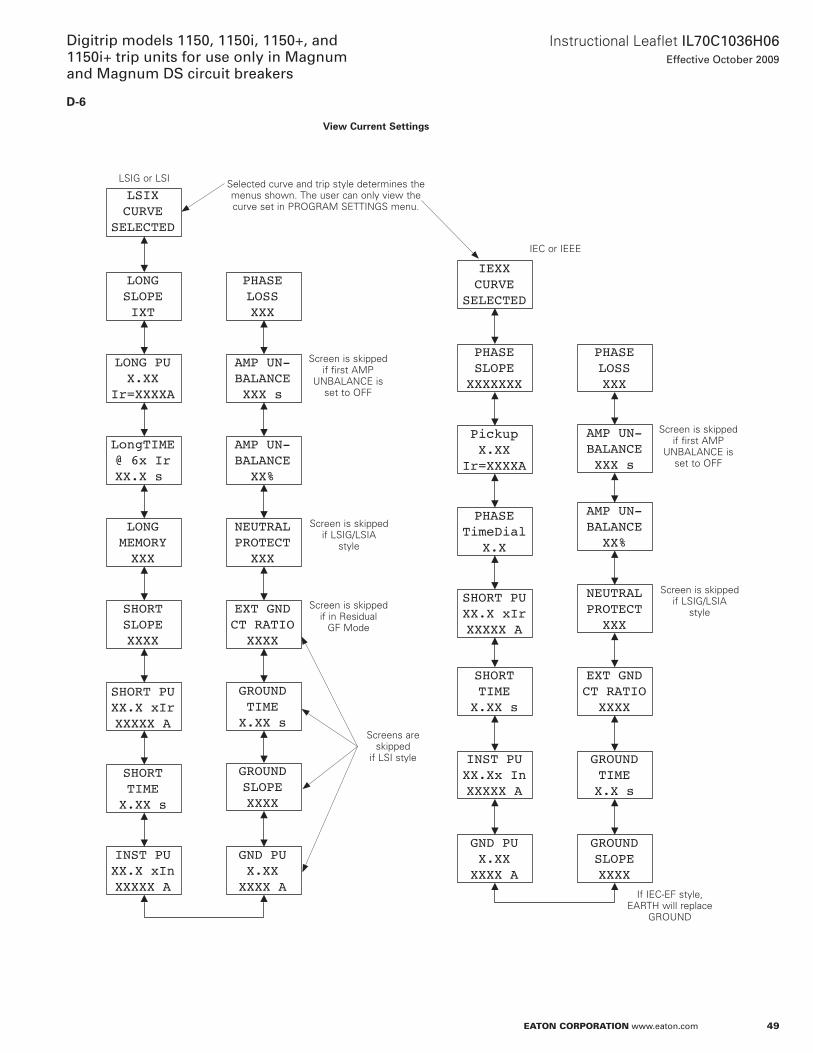
49
Instructional Leaflet IL70C1036H06Effective October 2009
Digitrip models 1150, 1150i, 1150+, and 1150i+ trip units for use only in Magnum and Magnum DS circuit breakers
eaton corporation www.eaton.com
D-6
SHORT PUXX.X xIrXXXXX A
INST PUXX.Xx InXXXXX A
GROUNDSLOPEXXXX
GND PUX.XXXXXX A
IEXXCURVE
SELECTED
PHASESLOPEXXXXXXX
PickupX.XX
Ir=XXXXA
PHASETimeDial
X.X
GROUNDTIMEX.X s
EXT GNDCT RATIOXXXX
NEUTRALPROTECTXXX
AMP UN-BALANCEXX%
AMP UN-BALANCEXXX s
PHASELOSSXXX
SHORTSLOPEXXXX
SHORT PUXX.X xIrXXXXX A
SHORTTIMEX.XX s
INST PUXX.X xInXXXXX A
LONGMEMORYXXX
LSIXCURVE
SELECTED
LONGSLOPEIXT
LONG PUX.XX
Ir=XXXXA
LongTIME@ 6x IrXX.X s
GROUNDSLOPEXXXX
GND PUX.XXXXXX A
GROUNDTIMEX.XX s
EXT GNDCT RATIOXXXX
NEUTRALPROTECTXXX
AMP UN-BALANCEXX%
AMP UN-BALANCEXXX s
PHASELOSSXXX
SHORTTIMEX.XX s
View Current Settings
LSIG or LSI Selected curve and trip style determines the menus shown . The user can only view the curve set in PRoGRaM SETTInGS menu .
IEC or IEEE
Screen is skipped if first aMP
UnBaLanCE is set to oFF
Screen is skipped if LSIG/LSIa
style
Screen is skipped if in Residual
GF Mode
Screens are skipped
if LSI style
Screen is skipped if first aMP
UnBaLanCE is set to oFF
Screen is skipped if LSIG/LSIa
style
If IEC-EF style, EaRTH will replace
GRoUnD
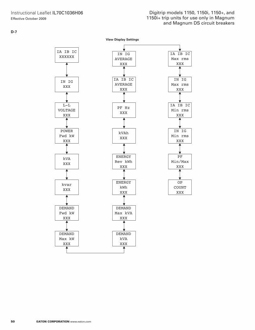
50
Instructional Leaflet IL70C1036H06Effective October 2009
Digitrip models 1150, 1150i, 1150+, and 1150i+ trip units for use only in Magnum
and Magnum DS circuit breakers
eaton corporation www.eaton.com
D-7
IN IGXXX
L-LVOLTAGEXXX
POWERFwd kWXXX
DEMANDMax kWXXX
DEMANDFwd kWXXX
kVAXXX
kvarXXX
IA IB ICXXXXXX
kVAhXXX
PF HzXXX
IA IB ICAVERAGEXXX
IN IGAVERAGEXXX
ENERGYRev kWhXXX
ENERGYkWhXXX
DEMANDkVAXXX
DEMANDMax kVAXXX
OPCOUNTXXX
IA IB ICMin rmsXXX
IN IGMax rmsXXX
IA IB ICMax rmsXXX
IN IGMin rmsXXX
PFMin/MaxXXX
View Display Settings
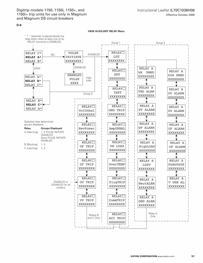
51
Instructional Leaflet IL70C1036H06Effective October 2009
Digitrip models 1150, 1150i, 1150+, and 1150i+ trip units for use only in Magnum and Magnum DS circuit breakers
eaton corporation www.eaton.com
D-8
RELAY C*RELAY A*RELAY B*
PULSEINITIATEXXXXXXXX
ENABLEDPULSEXXXX
RELAY A*RELAY B*RELAY C*
RELAY B*RELAY C*RELAY A*
RELAYLDT
XXXXXXXX
RELAYSDT
XXXXXXXX
RELAYINST
XXXXXXXX
RELAYGND TRIPXXXXXXXX
RELAYAmpUNBALXXXXXXXX
RELAYPH LOSSXXXXXXXX
RELAYOverTEMPXXXXXXXX
RELAYPlugTRIPXXXXXXXX
RELAYCommTRIPXXXXXXXX
RELAYACC TRIPXXXXXXXX
RELAYUV TRIPXXXXXXXX
RELAYOV TRIPXXXXXXXX
RELAYUF TRIPXXXXXXXX
RELAYOF TRIPXXXXXXXX
RELAYRevPowerXXXXXXXX
RELAYVolUnbalXXXXXXXX
RELAY AkW DMNDXXXXXXXX
RELAY ATHD ALRMXXXXXXXX
RELAY APF ALARMXXXXXXXX
RELAY AOP ALARMXXXXXXXX
RELAY AHighLOADXXXXXXXX
RELAY ALDPU
XXXXXXXX
RELAY ANeutALRMXXXXXXXX
RELAY AGND ALRMXXXXXXXX
RELAY AkVA DMNDXXXXXXXX
RELAY AUV ALARMXXXXXXXX
RELAY AOV ALARMXXXXXXXX
RELAY AUF ALARMXXXXXXXX
RELAY AOF ALARMXXXXXXXX
RELAY APhROTATEXXXXXXXX
RELAY AV UNB ALXXXXXXXX
VIEW AUxILIARY RELAY Menu
“ * “ (asterisk) is placed beside the relay letter when at least one of its
RELaY functions is EnaBLED .
DISaBLEDSEL
EnaBLEDVIEW
kVah kWh
Group 3
EnaBLED or DISaBLED for all
screens
Relays B and C only
Relay a only
Group 1 Group 2
Selected relay determines groups displayed .
Relay Groups Displayed
a (alarming) 1, 2 PULSE InITIaTE DISaBLED none PULSE InITIaTE EnaBLED
B (Blocking) 1, 3
C (Latching) 1, 3
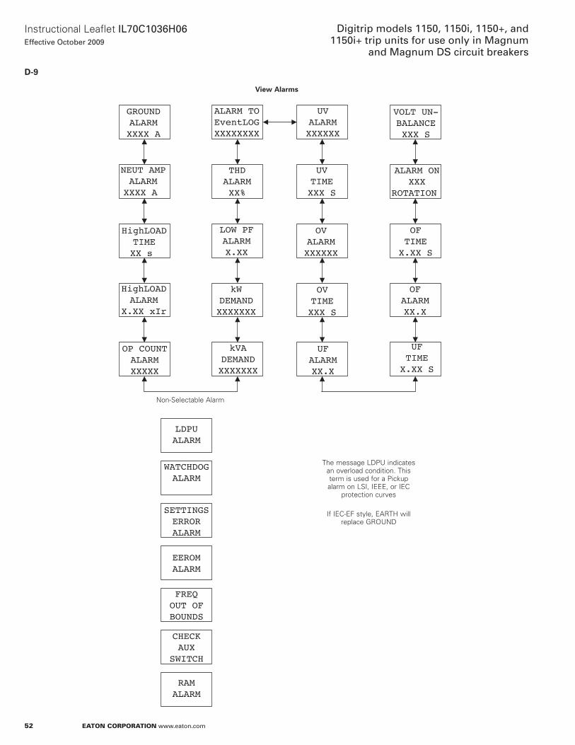
52
Instructional Leaflet IL70C1036H06Effective October 2009
Digitrip models 1150, 1150i, 1150+, and 1150i+ trip units for use only in Magnum
and Magnum DS circuit breakers
eaton corporation www.eaton.com
D-9
GROUNDALARMXXXX A
NEUT AMPALARMXXXX A
HighLOADALARM
X.XX xIr
OP COUNTALARMXXXXX
kVADEMANDXXXXXXX
HighLOADTIMEXX s
LOW PFALARMX.XX
THDALARMXX%
LDPUALARM
WATCHDOGALARM
SETTINGSERRORALARM
EEROMALARM
UVALARMXXXXXX
UVTIMEXXX S
OVTIMEXXX S
UFALARMXX.X
UFTIMEX.XX S
OFALARMXX.X
OVALARMXXXXXX
VOLT UN-BALANCEXXX S
OFTIMEX.XX S
ALARM ONXXX
ROTATION
FREQOUT OFBOUNDS
CHECKAUX
SWITCH
ALARM TOEventLOGXXXXXXXX
RAMALARM
kWDEMANDXXXXXXX
View Alarms
non-Selectable alarm
The message LDPU indicates an overload condition . This term is used for a Pickup alarm on LSI, IEEE, or IEC
protection curves
If IEC-EF style, EaRTH will replace GRoUnD
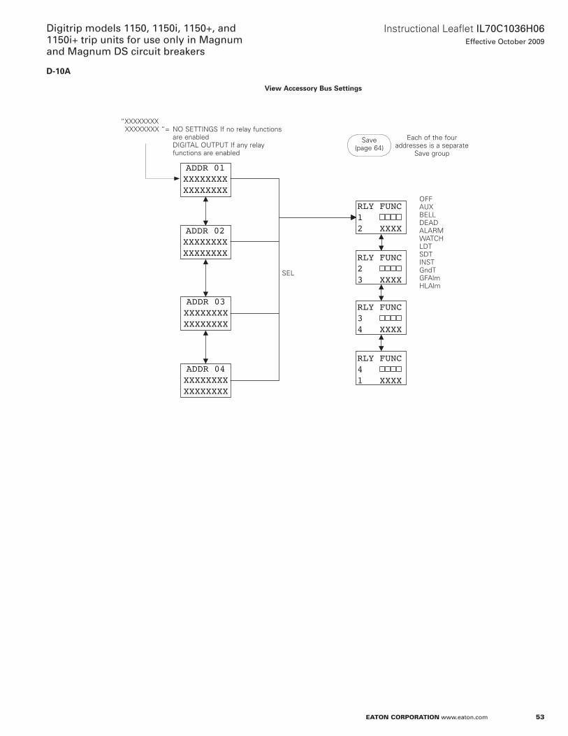
53
Instructional Leaflet IL70C1036H06Effective October 2009
Digitrip models 1150, 1150i, 1150+, and 1150i+ trip units for use only in Magnum and Magnum DS circuit breakers
eaton corporation www.eaton.com
D-10A
RLY FUNC12 XXXX
ADDR 04XXXXXXXXXXXXXXXX
ADDR 03XXXXXXXXXXXXXXXX
ADDR 02XXXXXXXXXXXXXXXX
ADDR 01XXXXXXXXXXXXXXXX
RLY FUNC23 XXXX
RLY FUNC34 XXXX
RLY FUNC41 XXXX
View Accessory Bus Settings
“xxxxxxxx xxxxxxxx “= no SETTInGS If no relay functions are enabled DIGITaL oUTPUT If any relay functions are enabled
Each of the four addresses is a separate
Save group
Save (page 64)
oFFaUxBELLDEaDaLaRMWaTCHLDTSDTInSTGndTGFalmHLalm
SEL
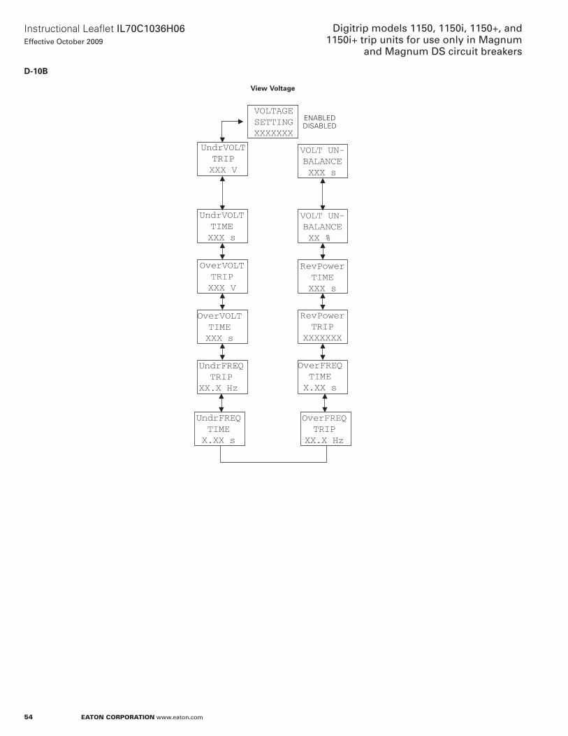
54
Instructional Leaflet IL70C1036H06Effective October 2009
Digitrip models 1150, 1150i, 1150+, and 1150i+ trip units for use only in Magnum
and Magnum DS circuit breakers
eaton corporation www.eaton.com
D-10B
OverVOLTTRIPXXX V
RevPowerTRIP
XXXXXXX
UndrVOLTTIMEXXX s
UndrVOLTTRIPXXX V
VOLTAGESETTINGXXXXXXX
UndrFREQTRIP
XX.X Hz
OverFREQTRIP
XX.X Hz
OverVOLTTIMEXXX s
UndrFREQTIMEX.XX s
OverFREQTIMEX.XX s
VOLT UN-BALANCEXX %
RevPowerTIMEXXX s
VOLT UN-BALANCEXXX s
View Voltage
EnaBLED DISaBLED
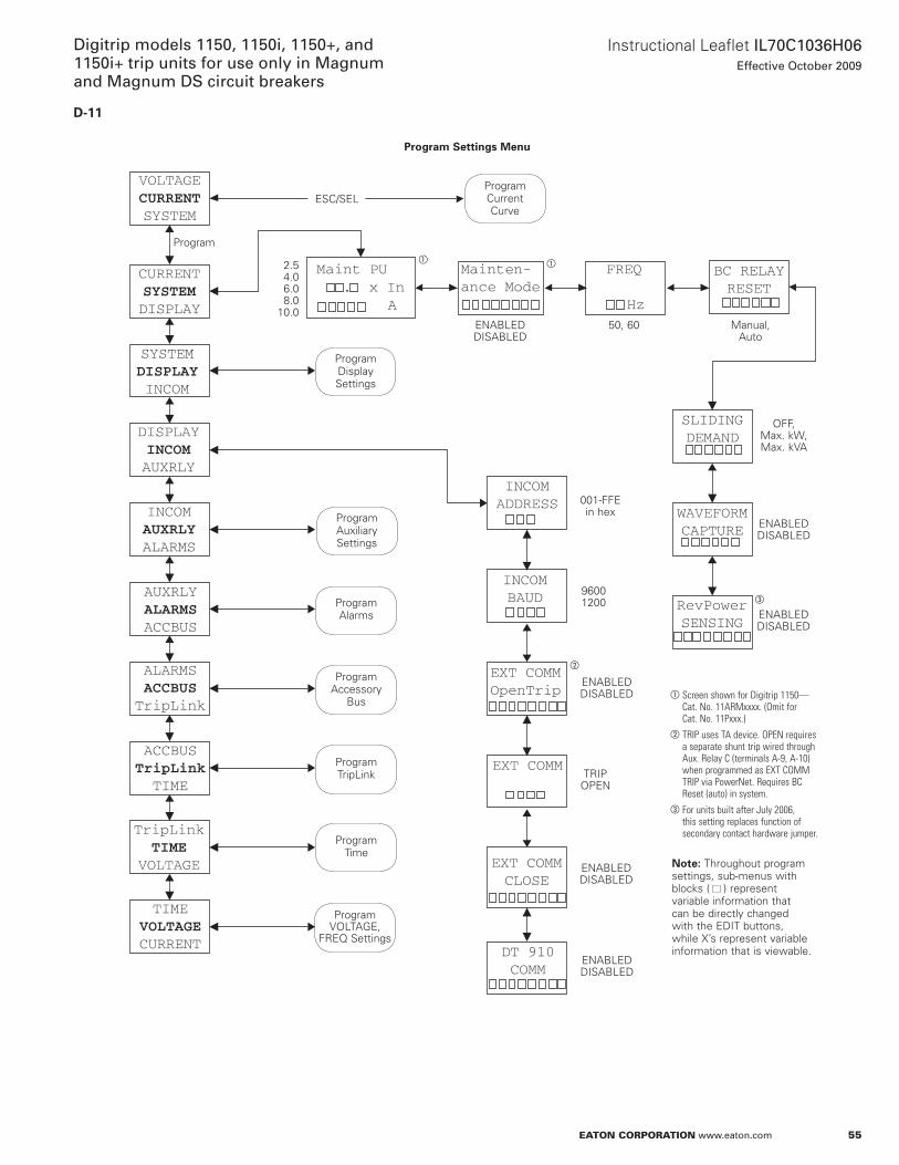
55
Instructional Leaflet IL70C1036H06Effective October 2009
Digitrip models 1150, 1150i, 1150+, and 1150i+ trip units for use only in Magnum and Magnum DS circuit breakers
eaton corporation www.eaton.com
D-11
VOLTAGECURRENTSYSTEM
FREQ
Hz
Maint PU
. x In
A
Mainten-ance Mode
CURRENTSYSTEMDISPLAY
SYSTEMDISPLAYINCOM
DISPLAYINCOMAUXRLY
INCOMAUXRLYALARMS
AUXRLYALARMSACCBUS
ALARMSACCBUSTripLink
ACCBUSTripLinkTIME
TripLinkTIME
VOLTAGE
TIMEVOLTAGECURRENT
DT 910COMM
EXT COMMCLOSE
EXT COMM
EXT COMMOpenTrip
INCOMBAUD
INCOMADDRESS
BC RELAYRESET
SLIDINGDEMAND
WAVEFORMCAPTURE
RevPowerSENSING
Program Settings Menu
ESC/SEL
Program
Program Current Curve
Program Display Settings
Program auxiliary Settings
Program alarms
Program accessory
Bus
Program VoLTaGE,
FREQ Settings
EnaBLED DISaBLED
a Screen shown for Digitrip 1150—Cat. No. 11ARMxxxx. (Omit for Cat. No. 11Pxxx.)
b TRIP uses TA device. OPEN requires a separate shunt trip wired through Aux. Relay C (terminals A-9, A-10) when programmed as ExT COMM TRIP via PowerNet. Requires BC Reset (auto) in system.
c For units built after July 2006, this setting replaces function of secondary contact hardware jumper.
Program TripLink
Program Time
otee:N Throughout program settings, sub-menus with blocks ( ) represent variable information that can be directly changed with the EDIT buttons, while x’s represent variable information that is viewable .
EnaBLED DISaBLED
TRIP oPEn
EnaBLED DISaBLED
9600 1200
001-FFE in hex
EnaBLED DISaBLED
EnaBLED DISaBLED
oFF, Max . kW, Max . kVa
Manual, auto
50, 60EnaBLED DISaBLED
2 .5 4 .0 6 .0 8 .0
10 .0
a a
b
c
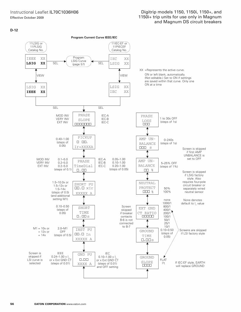
56
Instructional Leaflet IL70C1036H06Effective October 2009
Digitrip models 1150, 1150i, 1150+, and 1150i+ trip units for use only in Magnum
and Magnum DS circuit breakers
eaton corporation www.eaton.com
D-12
LSIG XXIEC XX
IEEE XXLSIG XX
SHORT PU. xIr
XXXXX A
INST PU.
XXXXX A
GROUNDSLOPE
GND PU
.XXXX A
PHASESLOPE
PICKUP.
Ir=XXXXA
PHASETimeDial
.
GROUNDTIME
s
EXT GNDCT RATIO
NEUTRALPROTECT
%
AMP UN-BALANCE
%
AMP UN-BALANCE
s
PHASELOSS
SHORTTIME.
IEC XXLSIG XX
.
LSIG XXIEEE XX
s
In
Program Current Curve IEEE/IEC
SEL
11LSIG or 11PLSIG
Catalog no .
Program LSIG Curve (page 57) SEL
VIEWVIEW
SEL SEL
MoD InV VERY InV ExT InV
IEC-a IEC-B IEC-C
0 .40–1 .00 (steps of
0 .05)
MoD InV VERY InV ExT InV
IEC-a IEC-B IEC-C
0 .1–5 .0 0 .2–5 .0 0 .2–5 .0
(steps of 0 .1)
0 .05–1 .00 0 .10–1 .00 0 .20–1 .00
(steps of 0 .05)
1 .5–10 .0x or 1 .5–12x or
1 .5–14x (steps of 0 .5) (and additional
setting M1)
0 .10–0 .50 (steps of
0 .05)
2 .0–M1 oFF
(steps of 0 .5)
M1 = 10x or = 12x or = 14x
IEEE 0 .24–1 .00 x In
or x Ext GnD CT (steps of 0 .01)
Screen is skipped if
LSI curve is selected
IEC 0 .10–1 .00 x In
or x Ext GnD CT (steps of 0 .01)
and oFF setting
Screen skipped
if breaker contacts B-6 is not connected
to B-7
FLaT I2t If IEC-EF style, EaRTH
will replace GRoUnD
Screens are skipped if LSI factory style
50% 100%
none 1000/1 800/1 400/1 200/1 100/1 50/1 25/1 10/1
0 .10–0 .50 (steps of
0 .05)
none denotes default to In value
5–25% oFF (steps of 1%)
0–240s (steps of 1s)
1 to 30s oFF (steps of 1s)
Screen is skipped if first aMP
UnBaLanCE is set to oFF
xx =Represents the active curve .
on or left blank, automatically . (not editable .) Set to on if settings are saved within that curve . only one on at a time
11IEC-EF or 11PIECEF
Catalog no .
Screen is skipped if LSIG factory
style . also requires four-pole circuit breaker or separately wired neutral sensor
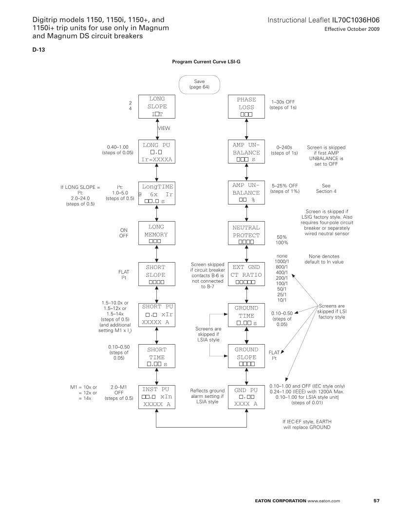
57
Instructional Leaflet IL70C1036H06Effective October 2009
Digitrip models 1150, 1150i, 1150+, and 1150i+ trip units for use only in Magnum and Magnum DS circuit breakers
eaton corporation www.eaton.com
D-13
INST PU. xIn
XXXXX A
GROUNDSLOPE
GND PU.
XXXX A
GROUNDTIME
EXT GNDCT RATIO
NEUTRALPROTECT
AMP UN-BALANCE
%
AMP UN-BALANCE
s
PHASELOSS
LONG PU.
Ir=XXXXA
LongTIME@ 6x Ir
LONGMEMORY
SHORTSLOPE
SHORT PU . xIrXXXXX A
SHORTTIME
LONGSLOPEI T
. s
. s
. s
Program Current Curve LSI-G
2 4
Save (page 64)
VIEW
FLaT I2t
1 .5–10 .0x or 1 .5–12x or
1 .5–14x (steps of 0 .5) (and additional setting M1 x In)
0 .10–0 .50 (steps of
0 .05)
2 .0–M1 oFF
(steps of 0 .5)
M1 = 10x or = 12x or = 14x
Screens are skipped if LSIa style
Screen skipped if circuit breaker contacts B-6 is not connected
to B-7
FLaT I2t
If IEC-EF style, EaRTH will replace GRoUnD
Screens are skipped if LSI factory style
50% 100%
none 1000/1 800/1 400/1 200/1 100/1 50/1 25/1 10/1
0 .10–0 .50 (steps of
0 .05)
none denotes default to In value
5–25% oFF (steps of 1%)
0–240s (steps of 1s)
1–30s oFF (steps of 1s)
Screen is skipped if first aMP
UnBaLanCE is set to oFF
See Section 4
0 .10–1 .00 and oFF (IEC style only) 0 .24–1 .00 (IEEE) with 1200a Max .
0 .10–1 .00 for LSIa style unit| (steps of 0 .01)
Reflects ground alarm setting if
LSIa style
Screen is skipped if LSIG factory style . also requires four-pole circuit
breaker or separately wired neutral sensor
on oFF
I4t:1 .0–5 .0
(steps of 0 .5)
If LonG SLoPE = I2t:
2 .0–24 .0 (steps of 0 .5)
0 .40–1 .00 (steps of 0 .05)
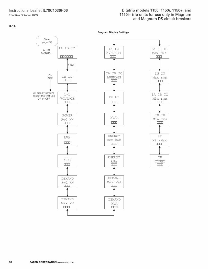
58
Instructional Leaflet IL70C1036H06Effective October 2009
Digitrip models 1150, 1150i, 1150+, and 1150i+ trip units for use only in Magnum
and Magnum DS circuit breakers
eaton corporation www.eaton.com
D-14
IN IG
L-LVOLTAGE
POWERFwd kW
DEMANDMax kW
DEMANDFwd kW
kVA
kvar
IA IB IC
kVAh
PF Hz
IA IB ICAVERAGE
IN IGAVERAGE
ENERGYRev kWh
ENERGYkWh
DEMANDkVA
DEMANDMax kVA
OPCOUNT
IA IB ICMin rms
IN IGMax rms
IA IB ICMax rms
IN IGMin rms
PFMin/Max
Program Display Settings
Save (page 64)
VIEW
on oFF
all display screens except the first use
on or oFF
aUTo ManUaL
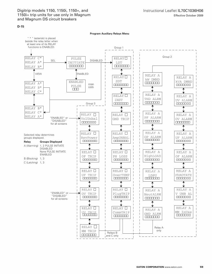
59
Instructional Leaflet IL70C1036H06Effective October 2009
Digitrip models 1150, 1150i, 1150+, and 1150i+ trip units for use only in Magnum and Magnum DS circuit breakers
eaton corporation www.eaton.com
D-15
RELAY C*RELAY A*
RELAY B*
RELAY A*RELAY B*RELAY C*
RELAY B*RELAY C*RELAY A*
RELAYLDT
RELAYSDT
RELAYINST
RELAYGND TRIP
RELAYAmpUNBAL
RELAYPH LOSS
RELAYOverTEMP
RELAYPlugTRIP
RELAYCommTRIP
RELAYVolUnbal
RELAYRevPower
RELAYOF TRIP
RELAYUF TRIP
RELAYOV TRIP
RELAYUV TRIP
RELAY AGND ALRM
RELAY ANeutALRM
RELAY ALDPU
RELAY AHighLOAD
RELAY AOP ALARM
RELAY AkW DMND
RELAY APF ALARM
RELAY ATHD ALRM
RELAY AUV ALARM
RELAY AOV ALARM
RELAY AUF ALARM
RELAY AOF ALARM
RELAY APhROTATE
RELAY AV UNB AL
RELAY AkVA DMND
RELAY AMM InUse
RELAYMM TRIP
PULSEINITIATE
ENABLEDPULSE
Program Auxiliary Relays Menu
“ * “ (asterisk) is placed beside the relay letter when
at least one of its RELaY functions is EnaBLED .
SEL DISaBLED
EnaBLED
kVah kWh
Group 3
Group 1
Group 2
VIEW
“EnaBLED” or “DISaBLED” for all screens
Selected relay determines groups displayed .
Relay Groups Displayed
a (alarming) 1, 2 PULSE InITIaTE DISaBLED none PULSE InITIaTE EnaBLED
B (Blocking) 1, 3
C (Latching) 1, 3
“EnaBLED” or “DISaBLED” for all screens
Relays B and C only
Relay a only
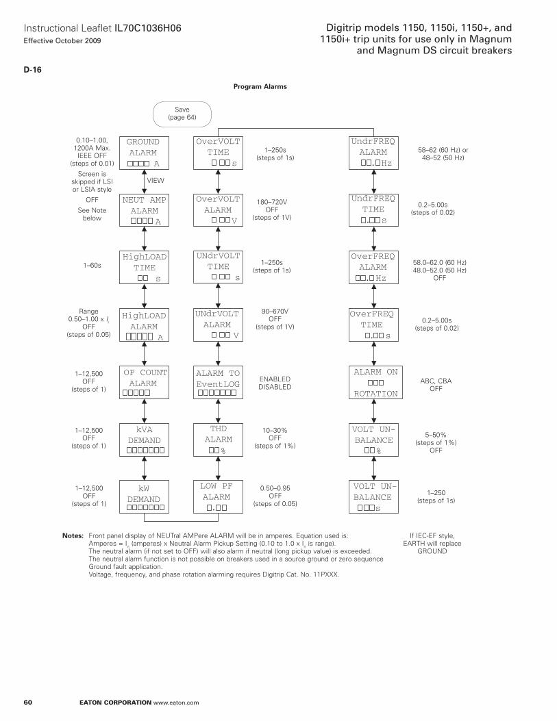
60
Instructional Leaflet IL70C1036H06Effective October 2009
Digitrip models 1150, 1150i, 1150+, and 1150i+ trip units for use only in Magnum
and Magnum DS circuit breakers
eaton corporation www.eaton.com
D-16
OverFREQTIME
. s
GROUNDALARM
A
HighLOADALARM A
NEUT AMPALARM
A
HighLOADTIME s
OP COUNTALARM
kVADEMAND
kWDEMAND
THDALARM
ALARM TOEventLOG
LOW PFALARM.
VOLT UN-BALANCE s
UNdrVOLTALARM
V
UNdrVOLTTIME
s
OverVOLTALARM V
OverVOLTTIME
s
UndrFREQALARM . Hz
UndrFREQTIME . s
OverFREQALARM
.. Hz
ALARM ON
ROTATION
VOLT UN-BALANCE
%%
Program Alarms
Save (page 64)
0 .10–1 .00, 1200a Max . IEEE oFF
(steps of 0 .01)
Screen is skipped if LSI or LSIa style
oFF
See note below
VIEW
1–60s
Range 0 .50–1 .00 x Ir
oFF (steps of 0 .05)
1–12,500 oFF
(steps of 1)
1–12,500 oFF
(steps of 1)
1–12,500 oFF
(steps of 1)
1–250s (steps of 1s)
90–670V oFF
(steps of 1V)
EnaBLED DISaBLED
10–30% oFF
(steps of 1%)
0 .50–0 .95 oFF
(steps of 0 .05)
180–720V oFF
(steps of 1V)
1–250s (steps of 1s)
58 .0–62 .0 (60 Hz) 48 .0–52 .0 (50 Hz)
oFF
0 .2–5 .00s (steps of 0 .02)
aBC, CBa oFF
5–50% (steps of 1%)
oFF
1–250 (steps of 1s)
0 .2–5 .00s (steps of 0 .02)
58–62 (60 Hz) or 48–52 (50 Hz)
otese:N Front panel display of nEUTral aMPere aLaRM will be in amperes . Equation used is: amperes = In (amperes) x neutral alarm Pickup Setting (0 .10 to 1 .0 x In is range) . The neutral alarm (if not set to oFF) will also alarm if neutral (long pickup value) is exceeded . The neutral alarm function is not possible on breakers used in a source ground or zero sequence Ground fault application . Voltage, frequency, and phase rotation alarming requires Digitrip Cat . no . 11Pxxx .
If IEC-EF style, EaRTH will replace
GRoUnD
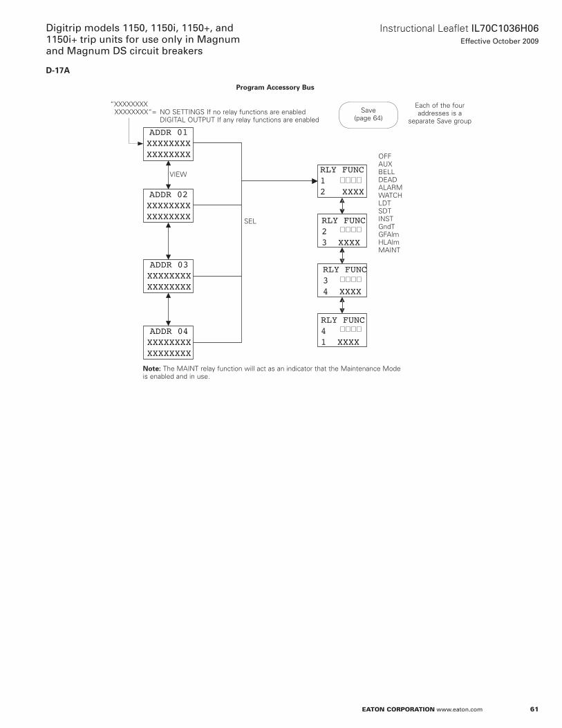
61
Instructional Leaflet IL70C1036H06Effective October 2009
Digitrip models 1150, 1150i, 1150+, and 1150i+ trip units for use only in Magnum and Magnum DS circuit breakers
eaton corporation www.eaton.com
D-17A
RLY FUNC12 XXXX
ADDR 04XXXXXXXXXXXXXXXX
ADDR 03XXXXXXXXXXXXXXXX
ADDR 02XXXXXXXXXXXXXXXX
ADDR 01XXXXXXXXXXXXXXXX
RLY FUNC23 XXXX
RLY FUNC34 XXXX
RLY FUNC41 XXXX
Program Accessory Bus
Save (page 64)
“xxxxxxxx xxxxxxxx“= no SETTInGS If no relay functions are enabled DIGITaL oUTPUT If any relay functions are enabled
VIEW
SEL
oFFaUxBELLDEaDaLaRMWaTCHLDTSDTInSTGndTGFalmHLalmMaInT
Each of the four addresses is a
separate Save group
otee:N The MaInT relay function will act as an indicator that the Maintenance Mode is enabled and in use .
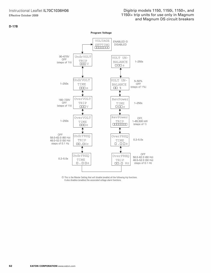
62
Instructional Leaflet IL70C1036H06Effective October 2009
Digitrip models 1150, 1150i, 1150+, and 1150i+ trip units for use only in Magnum
and Magnum DS circuit breakers
eaton corporation www.eaton.com
D-17B
OverVOLTTRIP
V
RevPowerTRIP
UndrVOLTTIME
s
UndrVOLTTRIP
V
VOLTAGESETTING
UndrFREQTRIP. Hz
OverFREQTRIP . Hz
OverVOLTTIME
s
UndrFREQTIME. s
OverFREQTIME. s
VOLT UN-BALANCE
%
RevPowerTIME
s
VOLT UN-BALANCE
s
Program Voltage
EnaBLED aDISaBLED
1–250s
5–50% oFF
(steps of 1%)
1–250s
oFF, 1–65,500 kW (steps of 1)
0 .2–5 .0s
oFF 58 .0–62 .0 (60 Hz) 48 .0–52 .0 (50 Hz) steps of 0 .1 Hz
0 .2–5 .0s
oFF 58 .0–62 .0 (60 Hz) 48 .0–52 .0 (50 Hz) steps of 0 .1 Hz
1–250s
180–720V oFF
(steps of 1V)
1–250s
90–670V oFF
(steps of 1V)
a This is the Master Setting that will disable (enable) all the following trip functions. It also disables (enables) the associated voltage alarm functions.
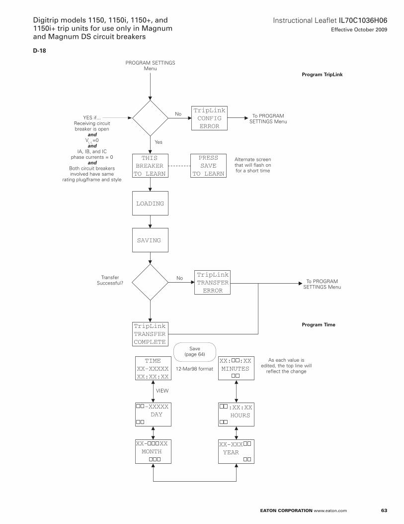
63
Instructional Leaflet IL70C1036H06Effective October 2009
Digitrip models 1150, 1150i, 1150+, and 1150i+ trip units for use only in Magnum and Magnum DS circuit breakers
eaton corporation www.eaton.com
D-18
TripLinkTRANSFERCOMPLETE
TripLinkCONFIGERROR
LOADING
-XXXXXDAY
XX- XXMONTH
-
XX-XXXYEAR
:XX:XXHOURS
XX: :XXMINUTES
TIMEXX-XXXXXXX:XX:XX
TripLinkTRANSFERERROR
THISBREAKERTO LEARN
PRESSSAVE
TO LEARN
SAVING
Program TripLink
Program Time
PRoGRaM SETTInGS Menu
no
Yes
To PRoGRaM SETTInGS Menu
alternate screen that will flash on for a short time
YES if . . . Receiving circuit breaker is open
andVL-L=0and
Ia, IB, and IC phase currents = 0
andBoth circuit breakers involved have same
rating plug/frame and style
noTo PRoGRaM
SETTInGS Menu
Transfer Successful?
Save (page 64)
12-Mar98 format
as each value is edited, the top line will
reflect the change
VIEW
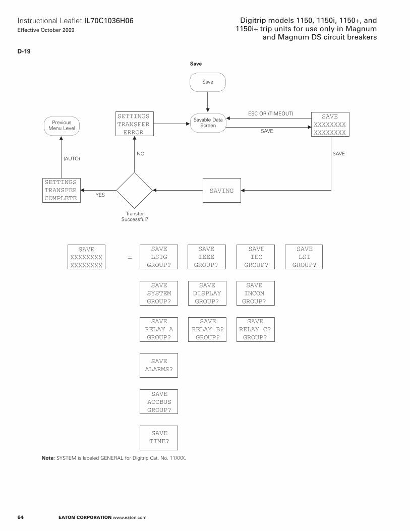
64
Instructional Leaflet IL70C1036H06Effective October 2009
Digitrip models 1150, 1150i, 1150+, and 1150i+ trip units for use only in Magnum
and Magnum DS circuit breakers
eaton corporation www.eaton.com
D-19
SAVELSIGGROUP?
SAVEIEEEGROUP?
SAVEXXXXXXXXXXXXXXXX
SETTINGSTRANSFERERROR
SAVING
SAVEXXXXXXXXXXXXXXXX
=
SETTINGSTRANSFERCOMPLETE
SAVEIEC
GROUP?
SAVESYSTEMGROUP?
SAVEDISPLAYGROUP?
SAVEINCOMGROUP?
SAVERELAY AGROUP?
SAVEALARMS?
SAVETIME?
SAVEACCBUSGROUP?
SAVERELAY B?GROUP?
SAVERELAY C?GROUP?
SAVELSI
GROUP?
Save
(aUTo)
YES
no SaVE
Transfer Successful?
otee:N SYSTEM is labeled GEnERaL for Digitrip Cat . no . 11xxx .
Save
Savable Data ScreenPrevious
Menu Level
ESC oR (TIMEoUT)
SaVE
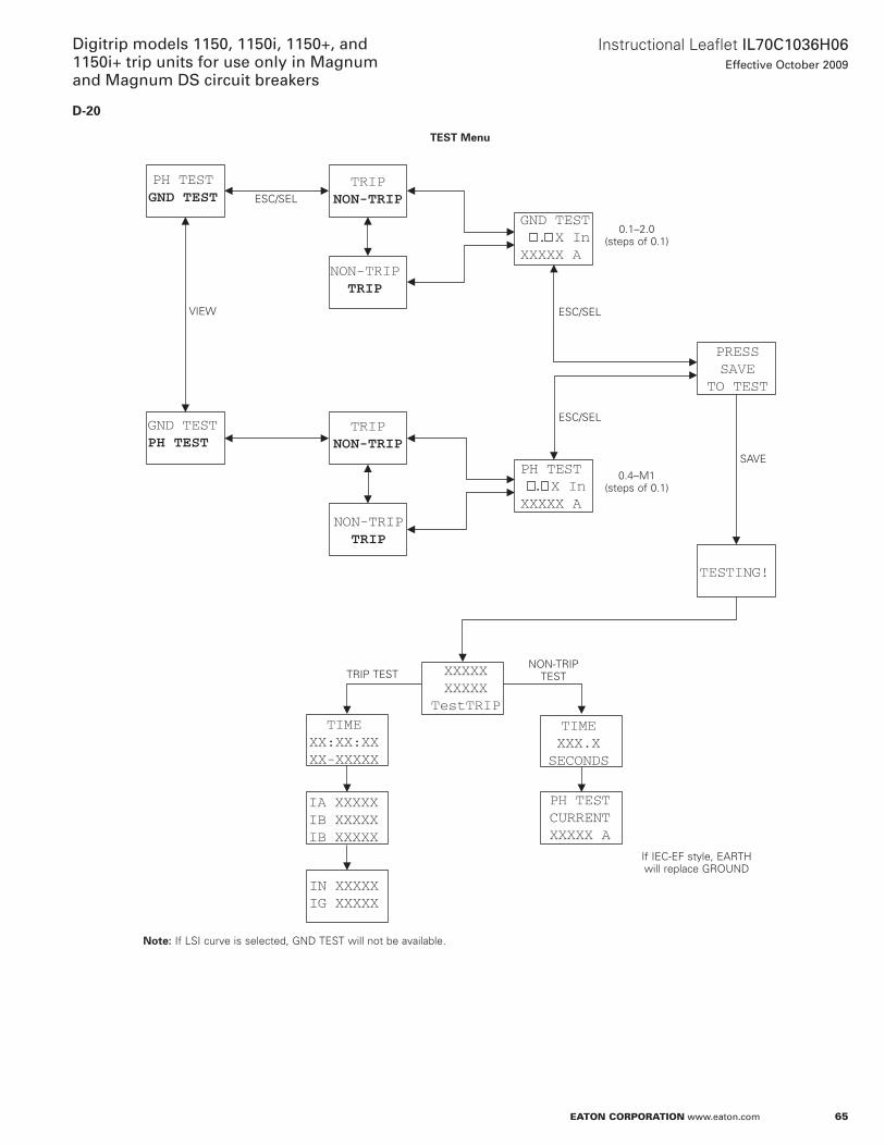
65
Instructional Leaflet IL70C1036H06Effective October 2009
Digitrip models 1150, 1150i, 1150+, and 1150i+ trip units for use only in Magnum and Magnum DS circuit breakers
eaton corporation www.eaton.com
D-20
PH TESTGND TEST
GND TESTPH TEST
TRIPNON-TRIP
NON-TRIPTRIP
TRIPNON-TRIP
NON-TRIPTRIP
GND TEST . X InXXXXX A
PH TEST . X InXXXXX A
TESTING!
PRESSSAVE
TO TEST
XXXXXXXXXX
TestTRIP
IA XXXXXIB XXXXXIB XXXXX
IN XXXXXIG XXXXX
TIMEXX:XX:XXXX-XXXXX
PH TESTCURRENTXXXXX A
TIMEXXX.XSECONDS
TEST Menu
otee:N If LSI curve is selected, GnD TEST will not be available .
ESC/SEL
VIEW ESC/SEL
ESC/SEL
SaVE
0 .1–2 .0 (steps of 0 .1)
0 .4–M1 (steps of 0 .1)
TRIP TESTnon-TRIP
TEST
If IEC-EF style, EaRTH will replace GRoUnD
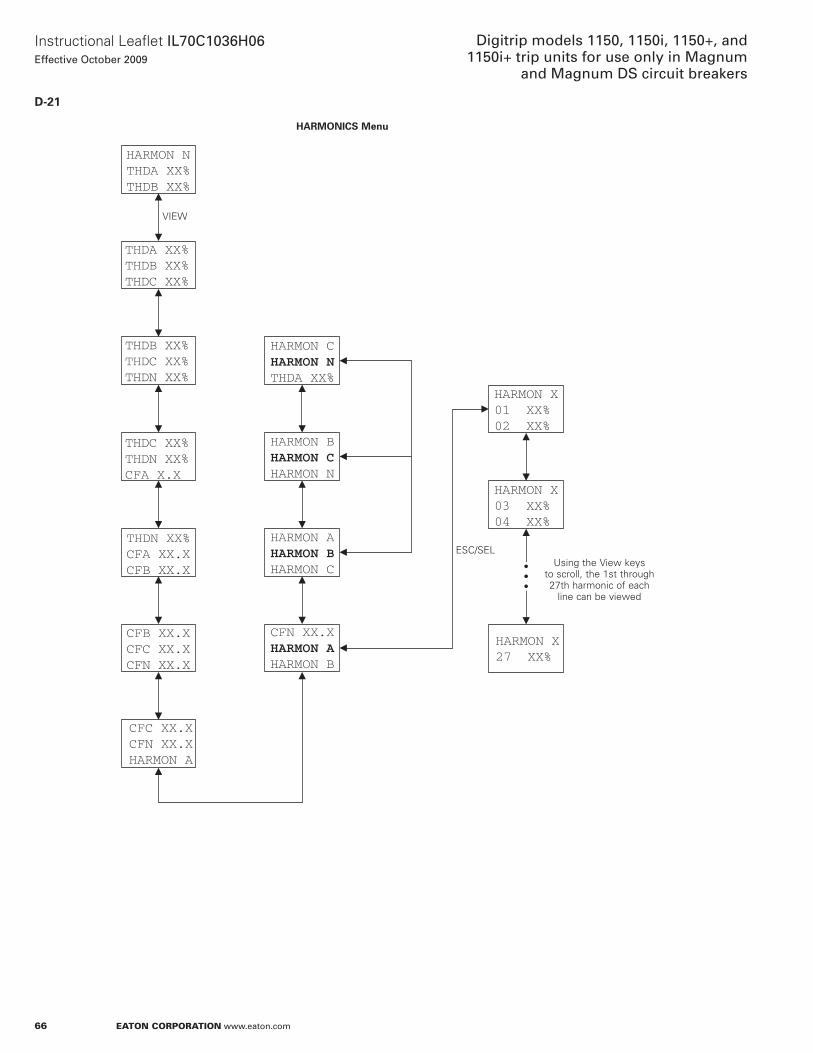
66
Instructional Leaflet IL70C1036H06Effective October 2009
Digitrip models 1150, 1150i, 1150+, and 1150i+ trip units for use only in Magnum
and Magnum DS circuit breakers
eaton corporation www.eaton.com
D-21
HARMON NTHDA XX%THDB XX%
HARMON X01 XX%02 XX%
HARMON X03 XX%04 XX%
HARMON X27 XX%
THDA XX%THDB XX%THDC XX%
THDB XX%THDC XX%THDN XX%
THDC XX%THDN XX%CFA X.X
THDN XX%CFA XX.XCFB XX.X
CFB XX.XCFC XX.XCFN XX.X
CFC XX.XCFN XX.XHARMON A
HARMON CHARMON NTHDA XX%
HARMON BHARMON CHARMON N
HARMON AHARMON BHARMON C
CFN XX.XHARMON AHARMON B
HARMONICS Menu
ESC/SEL
• • •
Using the View keys to scroll, the 1st through 27th harmonic of each
line can be viewed
VIEW
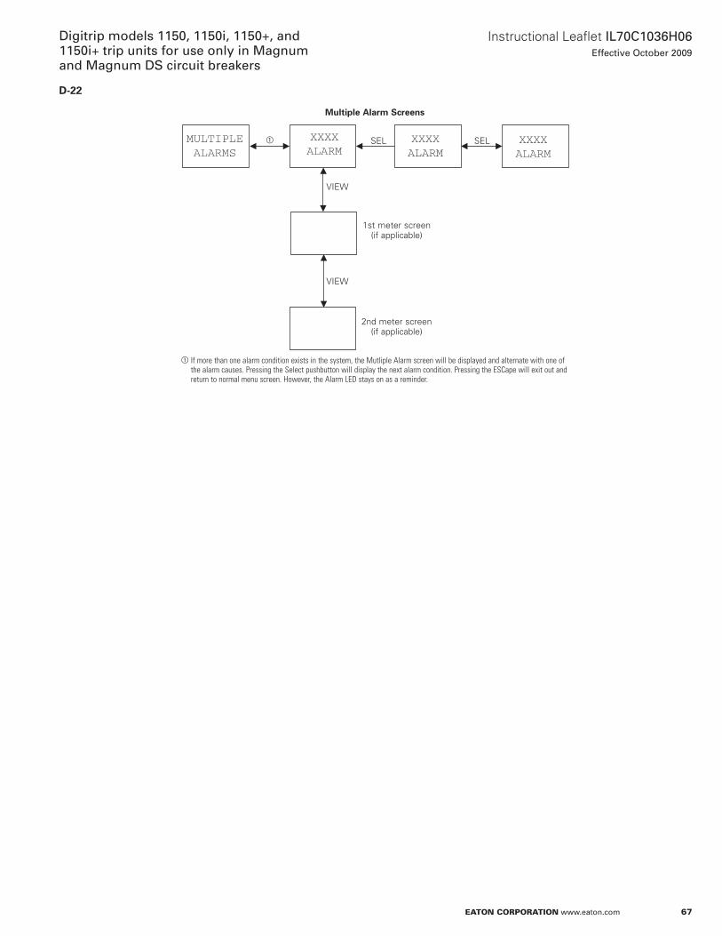
67
Instructional Leaflet IL70C1036H06Effective October 2009
Digitrip models 1150, 1150i, 1150+, and 1150i+ trip units for use only in Magnum and Magnum DS circuit breakers
eaton corporation www.eaton.com
D-22
MULTIPLEALARMS
XXXXALARM
XXXXALARM
XXXXALARM
Multiple Alarm Screens
a SEL SEL
VIEW
VIEW
1st meter screen (if applicable)
2nd meter screen (if applicable)
a If more than one alarm condition exists in the system, the Mutliple Alarm screen will be displayed and alternate with one of the alarm causes. Pressing the Select pushbutton will display the next alarm condition. Pressing the ESCape will exit out and return to normal menu screen. However, the Alarm LED stays on as a reminder.
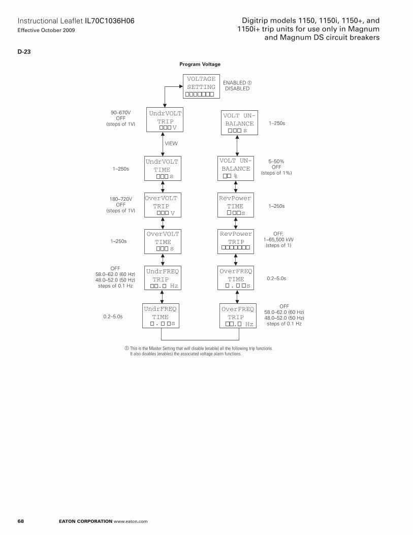
68
Instructional Leaflet IL70C1036H06Effective October 2009
Digitrip models 1150, 1150i, 1150+, and 1150i+ trip units for use only in Magnum
and Magnum DS circuit breakers
eaton corporation www.eaton.com
D-23
OverVOLTTRIP
V
RevPowerTRIP
UndrVOLTTIME
s
UndrVOLTTRIP
V
VOLTAGESETTING
UndrFREQTRIP . Hz
OverFREQTRIP . Hz
OverVOLTTIME
s
UndrFREQTIME. s
OverFREQTIME. s
VOLT UN-BALANCE
%
RevPowerTIME
s
VOLT UN-BALANCE
s
Program Voltage
EnaBLED aDISaBLED
1–250s
5–50% oFF
(steps of 1%)
1–250s
oFF, 1–65,500 kW (steps of 1)
0 .2–5 .0s
oFF 58 .0–62 .0 (60 Hz) 48 .0–52 .0 (50 Hz) steps of 0 .1 Hz
90–670V oFF
(steps of 1V)
1–250s
180–720V oFF
(steps of 1V)
1–250s
oFF 58 .0–62 .0 (60 Hz) 48 .0–52 .0 (50 Hz) steps of 0 .1 Hz
0 .2–5 .0s
a This is the Master Setting that will disable (enable) all the following trip functions. It also disables (enables) the associated voltage alarm functions.
VIEW
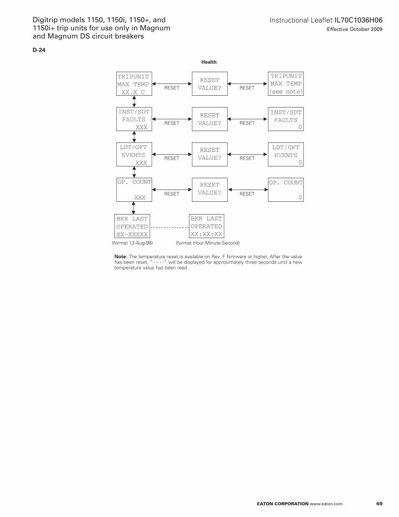
69
Instructional Leaflet IL70C1036H06Effective October 2009
Digitrip models 1150, 1150i, 1150+, and 1150i+ trip units for use only in Magnum and Magnum DS circuit breakers
eaton corporation www.eaton.com
D-24
INST/SDTFAULTS XXX
LDT/GFTEVENTS XXX
BKR LASTOPERATEDXX-XXXXX
OP. COUNT
XXX
OP. COUNT
TRIPUNITMAX TEMPXX.X C
RESETVALUE?
RESETVALUE?
BKR LASTOPERATEDXX:XX:XX
RESETVALUE?
RESETVALUE?
LDT/GFTEVENTS
INST/SDTFAULTS
0
0
0
TRIPUNITMAX TEMP(see note)
Health
RESET RESET
RESET RESET
RESET RESET
RESET RESET
(format 12-aug-98) (format Hour:Minute:Second)
otee:N The temperature reset is available on Rev . F firmware or higher . after the value has been reset, “ - - - -” will be displayed for approximately three seconds until a new temperature value has been read .
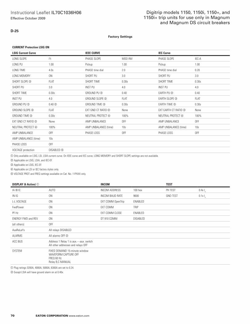
70
Instructional Leaflet IL70C1036H06Effective October 2009
Digitrip models 1150, 1150i, 1150+, and 1150i+ trip units for use only in Magnum
and Magnum DS circuit breakers
eaton corporation www.eaton.com
D-25Factory Settings
CURRENT Protection LSIG ON
LSIG Current Curve IEEE CURVE IEC Curve
LONG SLOPE I2t PHASE SLOPE MOD INV PHASE SLOPE IEC-A
LONG PU 1.00 Pickup 1.00 Pickup 1.00
LONG TIME 4.0s PHASE time dial 2.0 PHASE time dial 0.20
LONG MEMORY ON SHORT PU 3.0 SHORT PU 3.0
SHORT SLOPE c FLAT SHORT TIME 0.30s SHORT TIME 0.30s
SHORT PU 3.0 INST PU 4.0 INST PU 4.0
SHORT TIME 0.30s GROUND PU b 0.40 EARTH PU b 0.40
INST PU 4.0 GROUND SLOPE c FLAT EARTH SLOPE c FLAT
GROUND PU b 0.40 b GROUND TIME c 0.30s EARTH TIME c 0.30s
GROUND SLOPE c FLAT ExT GND CT RATIO b None ExT EARTH CT RATIO b None
GROUND TIME c 0.30s NEUTRAL PROTECT d 100% NEUTRAL PROTECT d 100%
ExT GND CT RATIO b None AMP UNBALANCE OFF AMP UNBALANCE OFF
NEUTRAL PROTECT d 100% AMP UNBALANCE (time) 10s AMP UNBALANCE (time) 10s
AMP UNBALANCE OFF PHASE LOSS OFF PHASE LOSS OFF
AMP UNBALANCE (time) 10s
PHASE LOSS OFF
VOLTAGE protection DISABLED e
a Only available on LSIG, LSI, LSIA current curve. On IEEE curve and IEC curve, LONG MEMORY and SHORT SLOPE settings are not available.b Applicable on LSIG, LSIA, and IEC-EF.c Applicable on LSIG, IEC-EF.d Applicable on LSI or IEC factory styles only.e VOLTAGE PROT and FREQ settings available on Cat. No. 11Pxxx only.
DISPLAY (6 Active) a INCOM TEST
IA IB IC AUTO INCOM ADDRESS 100 hex PH TEST 0.4x In
IN IG ON INCOM BAUD RATE 9600 GND TEST 0.1x In
L-L VOLTAGE ON ExT COMM OpenTrip ENABLED
FwdPower ON ExT COMM TRIP
PF Hz ON ExT COMM CLOSE ENABLED
ENERGY FWD and REV ON DT 910 COMM DISABLED
(all others) OFF
AuxReLaYs All relays DISABLED
ALARMS All alarms OFF b
ACC BUS Address 1 Relay 1 is aux.—aux. switchAll other addresses and relays OFF
SYSTEM FIxED DEMAND 15-minute windowWAVEFORM CAPTURE OFFFREQ 60 HzRelay B,C MANUAL
a Plug ratings 3200A, 4000A, 5000A, 6300A are set to 0.24.b Except LSIA will have ground alarm on at 0.40x.

71
Instructional Leaflet IL70C1036H06Effective October 2009
Digitrip models 1150, 1150i, 1150+, and 1150i+ trip units for use only in Magnum and Magnum DS circuit breakers
eaton corporation www.eaton.com
appendix e: Display abbreviationsGlossary of terms A–K
Abbreviation Definition Notes
a a, aMP amperes aCC accessory aCCBUS accessory bus aDDR address aLRM alarm ampUnBaL amperes out of balance aUx auxiliary auxRLY auxiliary relay aVG averageB BELL bell alarmC CF crest factor CoMM communications CommTRIP communications trip CT current transformerD DEaD deadman alarm DD day DMnD demand DT DigitripE Erth earth ESC ESCape pushbutton on Digitrip EVnT event ExT externalF FREQ frequency FreqT Frequency Trip FUnC function FwdPower forward powerG GFalm ground fault alarm GnD ground GroundPU ground pickupH HaRMon harmonic HH hours HLalm High Load alarm Hz hertzI Ia phase a current IB phase B current IC phase C current IEC International Electrotechnical Commission IEC-EF IEC Earth Fault IEEE Institute of Electrical and Electronics Engineers IG ground current In neutral current InST instantaneous InV inverse In maximum continuous current rating Ir continuous current ratingJK kVa kilovolt ampere kVah kilovolt ampere hour kvar kilovolt ampere reactive kW kilowatt kWh kilowatt hour
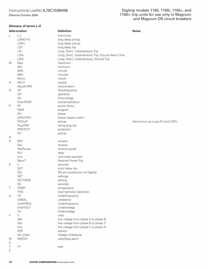
72
Instructional Leaflet IL70C1036H06Effective October 2009
Digitrip models 1150, 1150i, 1150+, and 1150i+ trip units for use only in Magnum
and Magnum DS circuit breakers
eaton corporation www.eaton.com
Glossary of terms L–Z
Abbreviation Definition Notes
L L-L line-to-line LonG PU long delay pickup LDPU long delay pickup LDT long delay trip LSI Long, Short, Instantaneous Trip LSIa Long, Short, Instantaneous Trip, Ground alarm only LSIG Long, Short, Instantaneous, Ground TripM Max maximum Min minimum MIn minute MM minutes Mmm monthn nEUT neutral neutaLRM neutral alarmo oF overfrequency oP operation oV overvoltage overTEMP overtemperatureP PF power factor PGM program PH phase phRoTaTE phase rotation alarm PICKUP pickup also known as Long PU and LDPU PlugTRIP rating plug trip PRoTECT protection PU pickupQR REV revision Rev reverse RevPower reverse power RLY relay rms root-mean-squared RpwrT Reverse Power TripS s seconds SDT short delay trip SEL SELect pushbutton on Digitrip SET settings SETTInGS setting SS secondsT TEMP temperature THD total harmonic distortionU UF Underfrequency UnBaL unbalance UndrFREQ Underfrequency UndrVoLT Undervoltage UV UndervoltageV V volts Vab line voltage from phase a to phase B Vbc line voltage from phase B to phase C Vca line voltage from phase C to phase a VER version Vol Unbal Voltage UnbalanceW WaTCH watchdog alarmxY YY yearZ
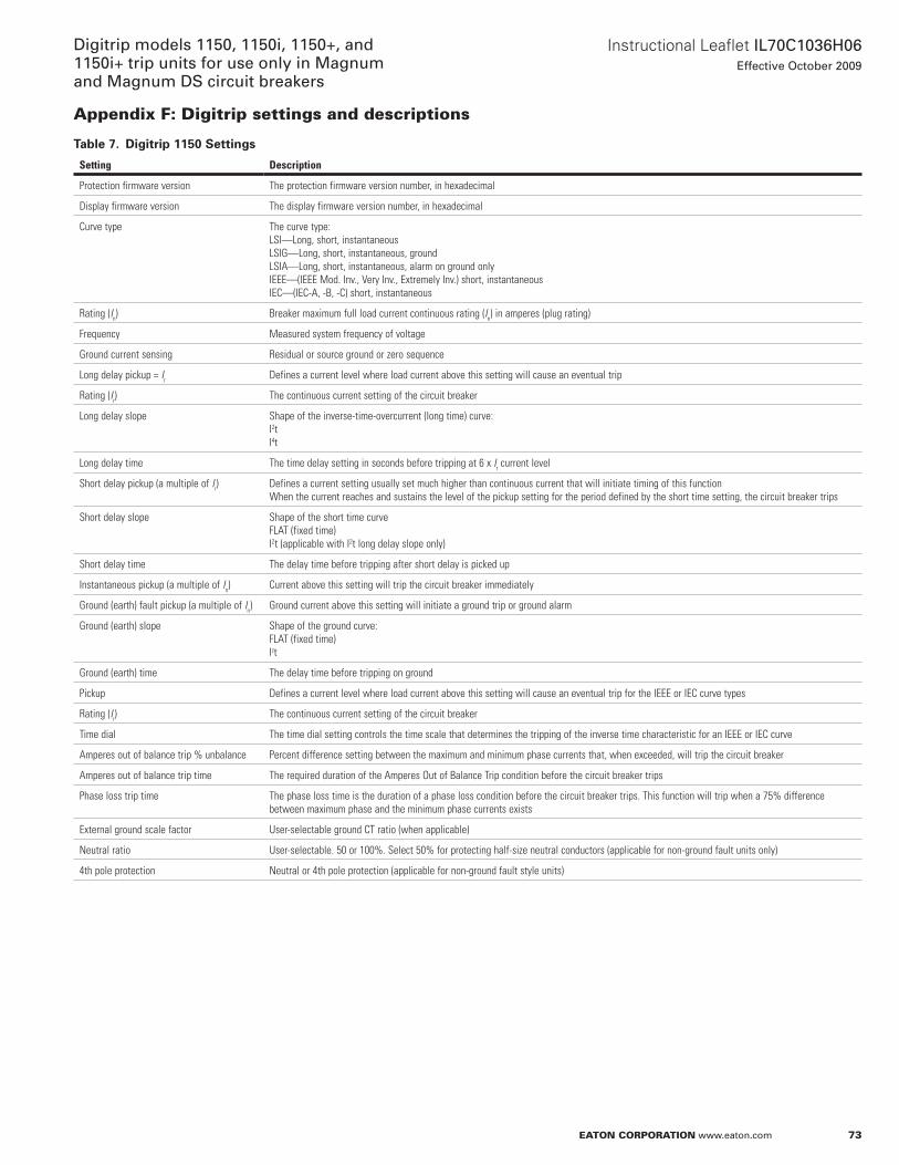
73
Instructional Leaflet IL70C1036H06Effective October 2009
Digitrip models 1150, 1150i, 1150+, and 1150i+ trip units for use only in Magnum and Magnum DS circuit breakers
eaton corporation www.eaton.com
appendix F: Digitrip settings and descriptions
Table 7. Digitrip 1150 Settings
Setting Description
Protection firmware version The protection firmware version number, in hexadecimal
Display firmware version The display firmware version number, in hexadecimal
Curve type The curve type:LSI—Long, short, instantaneousLSIG—Long, short, instantaneous, groundLSIA—Long, short, instantaneous, alarm on ground onlyIEEE—(IEEE Mod. Inv., Very Inv., Extremely Inv.) short, instantaneousIEC—(IEC-A, -B, -C) short, instantaneous
Rating (In) Breaker maximum full load current continuous rating (In) in amperes (plug rating)
Frequency Measured system frequency of voltage
Ground current sensing Residual or source ground or zero sequence
Long delay pickup = Ir Defines a current level where load current above this setting will cause an eventual trip
Rating (Ir) The continuous current setting of the circuit breaker
Long delay slope Shape of the inverse-time-overcurrent (long time) curve:I2tI4t
Long delay time The time delay setting in seconds before tripping at 6 x Ir current level
Short delay pickup (a multiple of Ir) Defines a current setting usually set much higher than continuous current that will initiate timing of this functionWhen the current reaches and sustains the level of the pickup setting for the period defined by the short time setting, the circuit breaker trips
Short delay slope Shape of the short time curveFLAT (fixed time)I2t (applicable with I2t long delay slope only)
Short delay time The delay time before tripping after short delay is picked up
Instantaneous pickup (a multiple of In) Current above this setting will trip the circuit breaker immediately
Ground (earth) fault pickup (a multiple of In) Ground current above this setting will initiate a ground trip or ground alarm
Ground (earth) slope Shape of the ground curve:FLAT (fixed time)Izt
Ground (earth) time The delay time before tripping on ground
Pickup Defines a current level where load current above this setting will cause an eventual trip for the IEEE or IEC curve types
Rating (Ir) The continuous current setting of the circuit breaker
Time dial The time dial setting controls the time scale that determines the tripping of the inverse time characteristic for an IEEE or IEC curve
Amperes out of balance trip % unbalance Percent difference setting between the maximum and minimum phase currents that, when exceeded, will trip the circuit breaker
Amperes out of balance trip time The required duration of the Amperes Out of Balance Trip condition before the circuit breaker trips
Phase loss trip time The phase loss time is the duration of a phase loss condition before the circuit breaker trips. This function will trip when a 75% difference between maximum phase and the minimum phase currents exists
External ground scale factor User-selectable ground CT ratio (when applicable)
Neutral ratio User-selectable. 50 or 100%. Select 50% for protecting half-size neutral conductors (applicable for non-ground fault units only)
4th pole protection Neutral or 4th pole protection (applicable for non-ground fault style units)
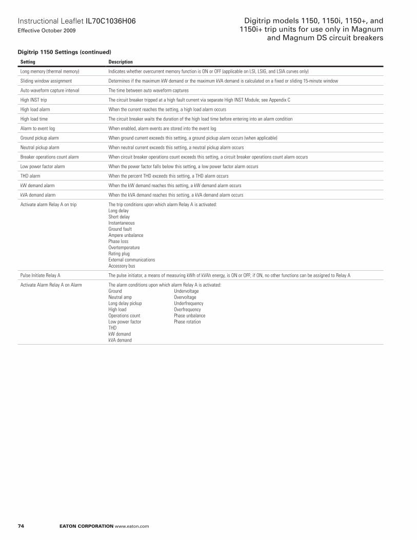
74
Instructional Leaflet IL70C1036H06Effective October 2009
Digitrip models 1150, 1150i, 1150+, and 1150i+ trip units for use only in Magnum
and Magnum DS circuit breakers
eaton corporation www.eaton.com
Digitrip 1150 Settings (continued)
Setting Description
Long memory (thermal memory) Indicates whether overcurrent memory function is ON or OFF (applicable on LSI, LSIG, and LSIA curves only)
Sliding window assignment Determines if the maximum kW demand or the maximum kVA demand is calculated on a fixed or sliding 15-minute window
Auto waveform capture interval The time between auto waveform captures
High INST trip The circuit breaker tripped at a high fault current via separate High INST Module; see Appendix C
High load alarm When the current reaches the setting, a high load alarm occurs
High load time The circuit breaker waits the duration of the high load time before entering into an alarm condition
Alarm to event log When enabled, alarm events are stored into the event log
Ground pickup alarm When ground current exceeds this setting, a ground pickup alarm occurs (when applicable)
Neutral pickup alarm When neutral current exceeds this setting, a neutral pickup alarm occurs
Breaker operations count alarm When circuit breaker operations count exceeds this setting, a circuit breaker operations count alarm occurs
Low power factor alarm When the power factor falls below this setting, a low power factor alarm occurs
THD alarm When the percent THD exceeds this setting, a THD alarm occurs
kW demand alarm When the kW demand reaches this setting, a kW demand alarm occurs
kVA demand alarm When the kVA demand reaches this setting, a kVA demand alarm occurs
Activate alarm Relay A on trip The trip conditions upon which alarm Relay A is activated:Long delayShort delayInstantaneousGround faultAmpere unbalancePhase lossOvertemperatureRating plugExternal communicationsAccessory bus
Pulse Initiate Relay A The pulse initiator, a means of measuring kWh of kVAh energy, is ON or OFF; if ON, no other functions can be assigned to Relay A
Activate Alarm Relay A on Alarm The alarm conditions upon which alarm Relay A is activated:Ground UndervoltageNeutral amp OvervoltageLong delay pickup UnderfrequencyHigh load OverfrequencyOperations count Phase unbalanceLow power factor Phase rotationTHDkW demandkVA demand
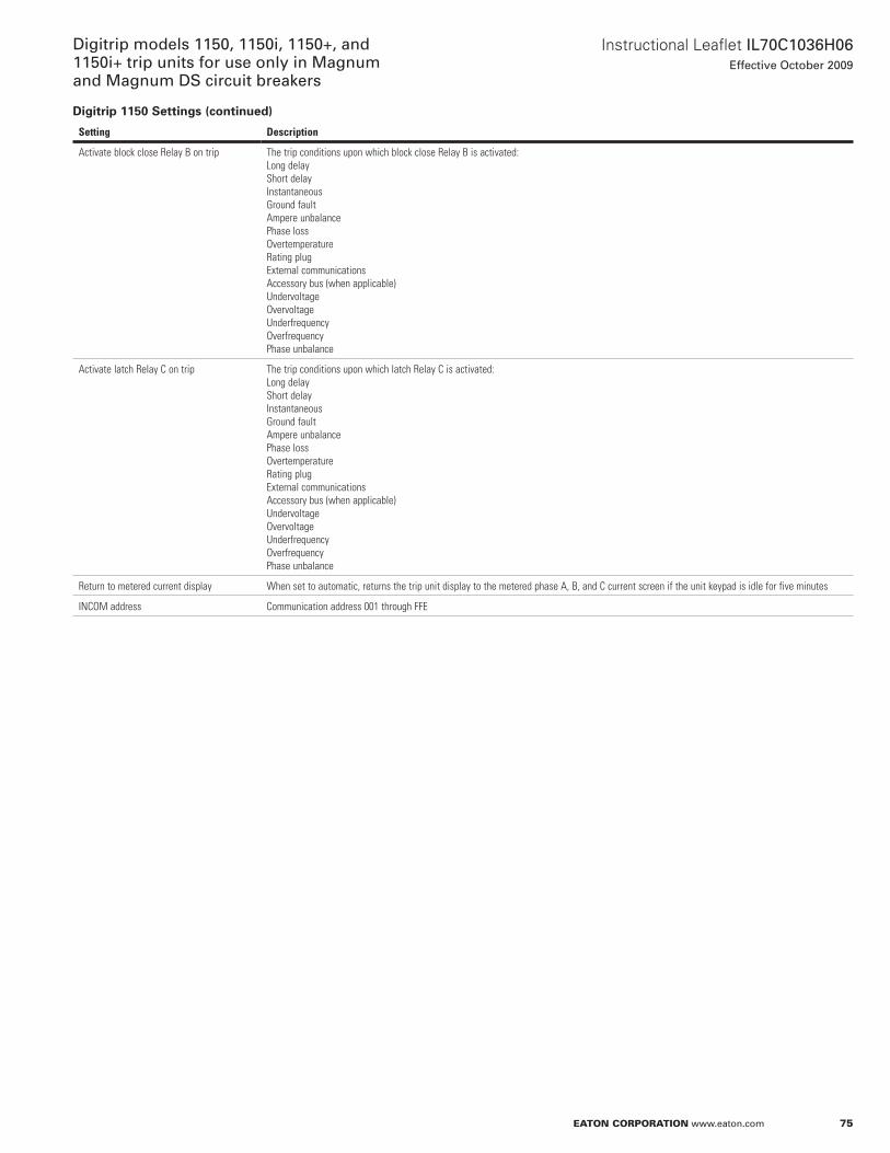
75
Instructional Leaflet IL70C1036H06Effective October 2009
Digitrip models 1150, 1150i, 1150+, and 1150i+ trip units for use only in Magnum and Magnum DS circuit breakers
eaton corporation www.eaton.com
Digitrip 1150 Settings (continued)
Setting Description
Activate block close Relay B on trip The trip conditions upon which block close Relay B is activated:Long delayShort delayInstantaneousGround faultAmpere unbalancePhase lossOvertemperatureRating plugExternal communicationsAccessory bus (when applicable)UndervoltageOvervoltageUnderfrequencyOverfrequencyPhase unbalance
Activate latch Relay C on trip The trip conditions upon which latch Relay C is activated:Long delayShort delayInstantaneousGround faultAmpere unbalancePhase lossOvertemperatureRating plugExternal communicationsAccessory bus (when applicable)UndervoltageOvervoltageUnderfrequencyOverfrequencyPhase unbalance
Return to metered current display When set to automatic, returns the trip unit display to the metered phase A, B, and C current screen if the unit keypad is idle for five minutes
INCOM address Communication address 001 through FFE
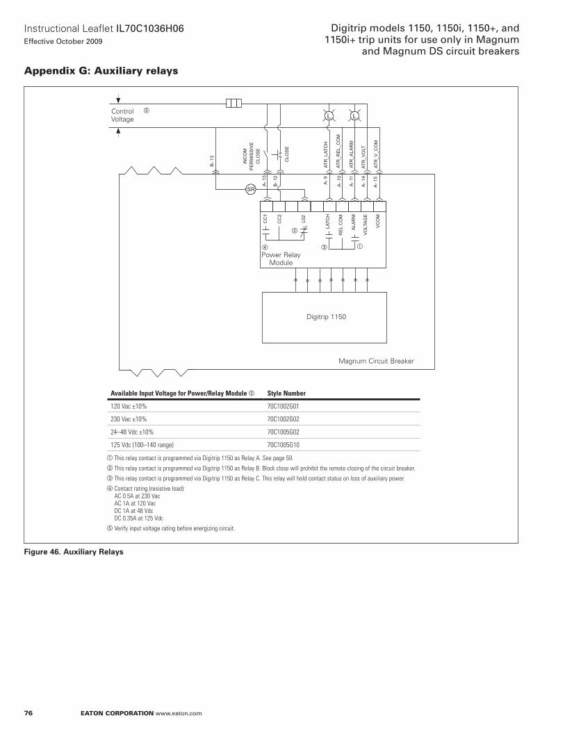
76
Instructional Leaflet IL70C1036H06Effective October 2009
Digitrip models 1150, 1150i, 1150+, and 1150i+ trip units for use only in Magnum
and Magnum DS circuit breakers
eaton corporation www.eaton.com
appendix G: auxiliary relays
Figure 46. Auxiliary Relays
I
NC
OM
PE
RM
ISS
IVE
C
LOS
E
RE
L C
OM
VO
LTA
GE
CC
2
L02
CC
1
ALA
RM
VC
OM
LATC
H
ATR
_ALA
RM
ATR
_VO
LT
ATR
_V_C
OM
ATR
_RE
L_C
OM
ATR
_LAT
CH
A- 1
3
CLO
SE
SR
L
B- 1
2
A- 9
A- 1
1
A- 1
0
B- 1
3
A- 1
5
A- 1
4
LControl Voltage
e
b
acd
Power Relay Module
Digitrip 1150
Magnum Circuit Breaker
Available Input Voltage for Power/Relay Module e Style Number
120 Vac ±10% 70C1002G01
230 Vac ±10% 70C1002G02
24–48 Vdc ±10% 70C1005G02
125 Vdc (100–140 range) 70C1005G10
a This relay contact is programmed via Digitrip 1150 as Relay A. See page 59. b This relay contact is programmed via Digitrip 1150 as Relay B. Block close will prohibit the remote closing of the circuit breaker.c This relay contact is programmed via Digitrip 1150 as Relay C. This relay will hold contact status on loss of auxiliary power.d Contact rating (resistive load):
AC 0.5A at 230 Vac AC 1A at 120 Vac DC 1A at 48 Vdc DC 0.35A at 125 Vdc
e Verify input voltage rating before energizing circuit.
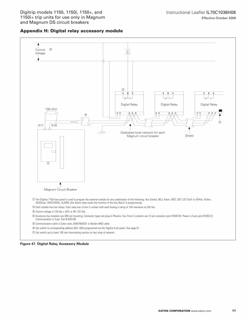
77
Instructional Leaflet IL70C1036H06Effective October 2009
Digitrip models 1150, 1150i, 1150+, and 1150i+ trip units for use only in Magnum and Magnum DS circuit breakers
eaton corporation www.eaton.com
appendix H: Digital relay accessory module
Figure 47. Digital Relay Accessory Module
LControl Voltage
c
b
a
e
g
Magnum Circuit Breaker
a The Digitrip 1150 front panel is used to program the external module for any combination of the following: Aux Switch, BELL Alarm, INST, SDT, LDT GndT or GFAlm, HLAlm, DEADman, WATCHDOG, ALARM, (the Alarm relay tracks the function of the Aux ReLaY A programming).
b Each module has four relays. Each relay has a Form C contact with each having a rating of 10A maximum at 250 Vac.c Control voltage is 120 Vac ± 20% or 48–125 Vdc.d Accessory bus modules use DIN rail mounting. Connector types are plug-in-Phoenix. Four Form C contacts use 12-pin connector part #1835193. Power is 5-pin part #1835122.
Communication is 3-pin. Part #1835106.e Communication cable is Eaton style 2A957805G01 or Belden 9463 cable.f Set switch to corresponding address (001–004) programmed via the Digitrip front panel. See page 61.g Set switch up to insert 100 ohm terminating resistor on last relay of network.
Dedicated local network for each Magnum circuit breaker Shield
Digital Relay Digital Relay Digital Relay
100 ohm
a18a17
78
Instructional Leaflet IL70C1036H06Effective October 2009
Digitrip models 1150, 1150i, 1150+, and 1150i+ trip units for use only in Magnum
and Magnum DS circuit breakers
eaton corporation www.eaton.com
appendix i: Modbus translator wiringThe Digitrip 1150 in a Magnum circuit breaker can communicate its data using Modbus RTU protocol by employing a mMInT device to act as a translator from InCoM communication to Modbus communications . a Modbus master device is shown wired to gather data and can provide control logic to open and close circuit breakers .
The mMInT Module Cat . no . mMInT uses DIn rail mounting . Connector types are plug-in-Phoenix . Power is 5-pin .
InCoM network uses a 3-pin . The RS-485 Modbus uses a 4-pin connector that consists of signals a, B, CoMmon, and SHielD .
Three baud rates of 1200, 9600, or 19200 are selectable via programming switch for the Modbus network . The InCoM baud rate is fixed at 9600 baud .
Figure 48. Modbus Translator Wiring
Digitrip 1150
Digitrip 1150
B-2B-1 B-2B-1
A B COM SHD
COM Inv Non Invert Input
d
Magnum Circuit Breaker
a Control voltage is 120 Vac ± 20% or 24–125 Vdc.b Communication cable is Eaton style 2A957805G01 or Belden 9463 cable.c The overall network will support up to 32 devices with any addresses from 1–247.d Terminating resistor is 121 ohm 1 watt. Use the mMINT switches to insert these terminators at the mMINT device.e Ground cable shield at this terminal.
b
Magnum Circuit Breaker
d
c
d
a
mMInTModbus Master
e
e

79
Instructional Leaflet IL70C1036H06Effective October 2009
Digitrip models 1150, 1150i, 1150+, and 1150i+ trip units for use only in Magnum and Magnum DS circuit breakers
eaton corporation www.eaton.com
Eaton CorporationElectrical Sector1000 Cherrington ParkwayMoon Township, Pa 15108United States877-ETn-CaRE (877-386-2273)Eaton .com
© 2009 Eaton Corporationall Rights ReservedPrinted in USaPublication no . IL70C1036H06 / Z8816october 2009
PowerChain Management is a registered trademark of Eaton Corporation .
all other trademarks are property of their respective owners .
Instructional Leaflet IL70C1036H06Effective October 2009
Digitrip models 1150, 1150i, 1150+, and 1150i+ trip units for use only in Magnum
and Magnum DS circuit breakers
Disclaimer of warranties and limitation of liabilityThe information, recommendations, descriptions, and safety notations in this document are based on Eaton Corporation’s (“Eaton”) experience and judgment, and may not cover all contingencies . If further information is required, an Eaton sales office should be consulted .
Sale of the product shown in this literature is subject to the terms and conditions outlined in appropriate Eaton selling policies or other contractual agreement between Eaton and the purchaser .
THERE aRE no UnDERSTanDInGS, aGREEMEnTS, WaRRanTIES, ExPRESSED oR IMPLIED, InCLUDInG WaRRanTIES oF FITnESS FoR a PaRTICULaR PURPoSE oR MERCHanTaBILITY, oTHER THan THoSE SPECIFICaLLY SET oUT In anY ExISTInG ConTRaCT BETWEEn THE PaRTIES . anY SUCH ConTRaCT STaTES THE EnTIRE oBLIGaTIon oF EaTon .
THE ConTEnTS oF THIS DoCUMEnT SHaLL noT BECoME PaRT oF oR MoDIFY anY ConTRaCT BETWEEn THE PaRTIES .
In no event will Eaton be responsible to the purchaser or user in contract, in tort (including negligence), strict liability, or otherwise for any special, indirect, incidental, or consequential damage or loss whatsoever, including but not limited to damage or loss of use of equipment, plant or power system, cost of capital, loss of power, additional expenses in the use of existing power facilities, or claims against the purchaser or user by its customers resulting from the use of the information, recommendations, and descriptions contained herein .
The information contained in this manual is subject to change without notice .


