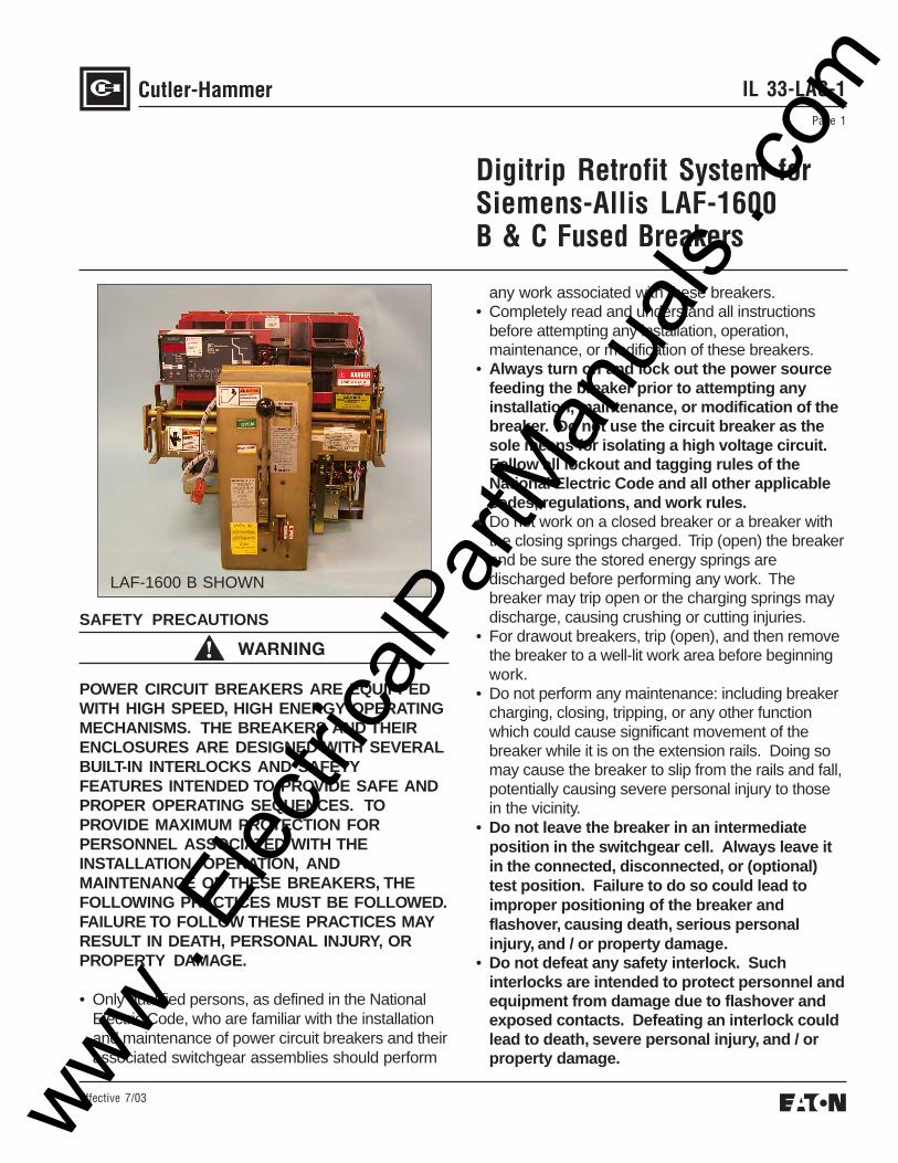
IL 33-LAC-1 Page 1 Effective 7/03 Digitrip Retrofit System for Siemens-Allis LAF-1600 B & C Fused Breakers SAFETY PRECAUTIONS WARNING POWER CIRCUIT BREAKERS ARE EQUIPPED WITH HIGH SPEED, HIGH ENERGY OPERATING MECHANISMS. THE BREAKERS AND THEIR ENCLOSURES ARE DESIGNED WITH SEVERAL BUILT-IN INTERLOCKS AND SAFETY FEATURES INTENDED TO PROVIDE SAFE AND PROPER OPERATING SEQUENCES. TO PROVIDE MAXIMUM PROTECTION FOR PERSONNEL ASSOCIATED WITH THE INSTALLATION, OPERATION, AND MAINTENANCE OF THESE BREAKERS, THE FOLLOWING PRACTICES MUST BE FOLLOWED. FAILURE TO FOLLOW THESE PRACTICES MAY RESULT IN DEATH, PERSONAL INJURY, OR PROPERTY DAMAGE. • Only qualified persons, as defined in the National Electric Code, who are familiar with the installation and maintenance of power circuit breakers and their associated switchgear assemblies should perform any work associated with these breakers. • Completely read and understand all instructions before attempting any installation, operation, maintenance, or modification of these breakers. • Always turn off and lock out the power source feeding the breaker prior to attempting any installation, maintenance, or modification of the breaker. Do not use the circuit breaker as the sole means for isolating a high voltage circuit. Follow all lockout and tagging rules of the National Electric Code and all other applicable codes, regulations, and work rules. • Do not work on a closed breaker or a breaker with the closing springs charged. Trip (open) the breaker and be sure the stored energy springs are discharged before performing any work. The breaker may trip open or the charging springs may discharge, causing crushing or cutting injuries. • For drawout breakers, trip (open), and then remove the breaker to a well-lit work area before beginning work. • Do not perform any maintenance: including breaker charging, closing, tripping, or any other function which could cause significant movement of the breaker while it is on the extension rails. Doing so may cause the breaker to slip from the rails and fall, potentially causing severe personal injury to those in the vicinity. • Do not leave the breaker in an intermediate position in the switchgear cell. Always leave it in the connected, disconnected, or (optional) test position. Failure to do so could lead to improper positioning of the breaker and flashover, causing death, serious personal injury, and / or property damage. • Do not defeat any safety interlock. Such interlocks are intended to protect personnel and equipment from damage due to flashover and exposed contacts. Defeating an interlock could lead to death, severe personal injury, and / or property damage. LAF-1600 B SHOWN www . ElectricalPartManuals . com
Transcript
IL 33-LAC-1Page 1
Effective 7/03
Digitrip Retrofit System forSiemens-Allis LAF-1600B & C Fused Breakers
SAFETY PRECAUTIONS
WARNING
POWER CIRCUIT BREAKERS ARE EQUIPPEDWITH HIGH SPEED, HIGH ENERGY OPERATINGMECHANISMS. THE BREAKERS AND THEIRENCLOSURES ARE DESIGNED WITH SEVERALBUILT-IN INTERLOCKS AND SAFETYFEATURES INTENDED TO PROVIDE SAFE ANDPROPER OPERATING SEQUENCES. TOPROVIDE MAXIMUM PROTECTION FORPERSONNEL ASSOCIATED WITH THEINSTALLATION, OPERATION, ANDMAINTENANCE OF THESE BREAKERS, THEFOLLOWING PRACTICES MUST BE FOLLOWED.FAILURE TO FOLLOW THESE PRACTICES MAYRESULT IN DEATH, PERSONAL INJURY, ORPROPERTY DAMAGE.
• Only qualified persons, as defined in the NationalElectric Code, who are familiar with the installationand maintenance of power circuit breakers and theirassociated switchgear assemblies should perform
any work associated with these breakers.• Completely read and understand all instructions
before attempting any installation, operation,maintenance, or modification of these breakers.
• Always turn off and lock out the power sourcefeeding the breaker prior to attempting anyinstallation, maintenance, or modification of thebreaker. Do not use the circuit breaker as thesole means for isolating a high voltage circuit.Follow all lockout and tagging rules of theNational Electric Code and all other applicablecodes, regulations, and work rules.
• Do not work on a closed breaker or a breaker withthe closing springs charged. Trip (open) the breakerand be sure the stored energy springs aredischarged before performing any work. Thebreaker may trip open or the charging springs maydischarge, causing crushing or cutting injuries.
• For drawout breakers, trip (open), and then removethe breaker to a well-lit work area before beginningwork.
• Do not perform any maintenance: including breakercharging, closing, tripping, or any other functionwhich could cause significant movement of thebreaker while it is on the extension rails. Doing somay cause the breaker to slip from the rails and fall,potentially causing severe personal injury to thosein the vicinity.
• Do not leave the breaker in an intermediateposition in the switchgear cell. Always leave itin the connected, disconnected, or (optional)test position. Failure to do so could lead toimproper positioning of the breaker andflashover, causing death, serious personalinjury, and / or property damage.
• Do not defeat any safety interlock. Suchinterlocks are intended to protect personnel andequipment from damage due to flashover andexposed contacts. Defeating an interlock couldlead to death, severe personal injury, and / orproperty damage.
LAF-1600 B SHOWN
www . El
ectric
alPar
tMan
uals
. com
IL 33-LAC-1Page 2
Effective 7/03
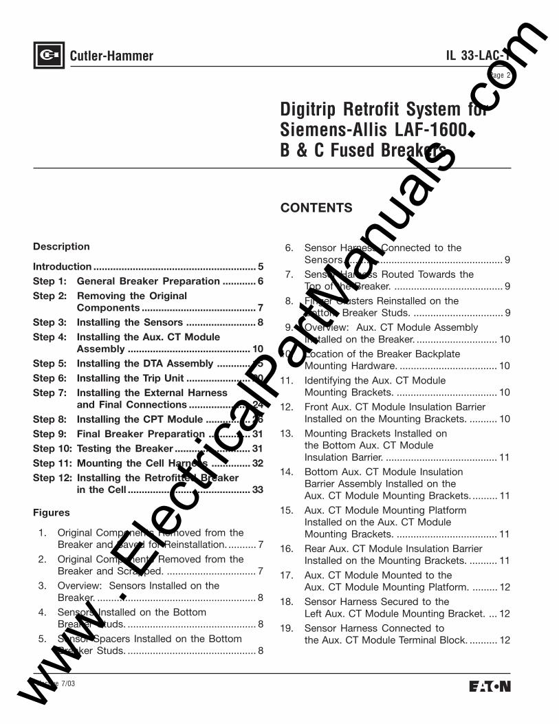
CONTENTS
Digitrip Retrofit System forSiemens-Allis LAF-1600B & C Fused Breakers
Description
Introduction .......................................................... 5Step 1: General Breaker Preparation ............ 6Step 2: Removing the Original
Components ......................................... 7Step 3: Installing the Sensors ......................... 8Step 4: Installing the Aux. CT Module
Assembly ............................................ 10Step 5: Installing the DTA Assembly ............ 15Step 6: Installing the Trip Unit ....................... 20Step 7: Installing the External Harness
and Final Connections ...................... 24Step 8: Installing the CPT Module ................ 26Step 9: Final Breaker Preparation ............... 31Step 10: Testing the Breaker ........................... 31Step 11: Mounting the Cell Harness .............. 32Step 12: Installing the Retrofitted Breaker
in the Cell ............................................ 33
Figures
1. Original Components Removed from theBreaker and Saved for Reinstallation. .......... 7
2. Original Components Removed from theBreaker and Scrapped. ................................ 7
3. Overview: Sensors Installed on theBreaker. ......................................................... 8
4. Sensors Installed on the BottomBreaker Studs. .............................................. 8
5. Sensor Spacers Installed on the BottomBreaker Studs. .............................................. 8
6. Sensor Harness Connected to theSensors. ........................................................ 9
7. Sensor Harness Routed Towards theTop of the Breaker. ....................................... 9
8. Finger Clusters Reinstalled on theBottom Breaker Studs. ................................ 9
9. Overview: Aux. CT Module AssemblyInstalled on the Breaker. ............................. 10
10. Location of the Breaker BackplateMounting Hardware. ................................... 10
11. Identifying the Aux. CT ModuleMounting Brackets. .................................... 10
12. Front Aux. CT Module Insulation BarrierInstalled on the Mounting Brackets. .......... 10
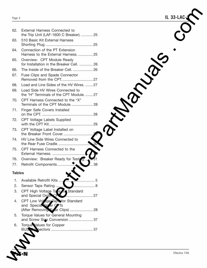
3. CPT High Voltage Taps for Standardand Special Order CPTs ............................. 27
4. CPT Low Voltage Taps for Standardand Special Order CPTs(After Removing Fuse Clips) ...................... 28
5. Torque Values for General Mountingand Screw Size Conversion ....................... 37
6. Torque Values for CopperBUS Connectors ........................................ 37
www . El
ectric
alPar
tMan
uals
. com
Effective 7/03
Page 5IL 33-LAC-1
INTRODUCTION
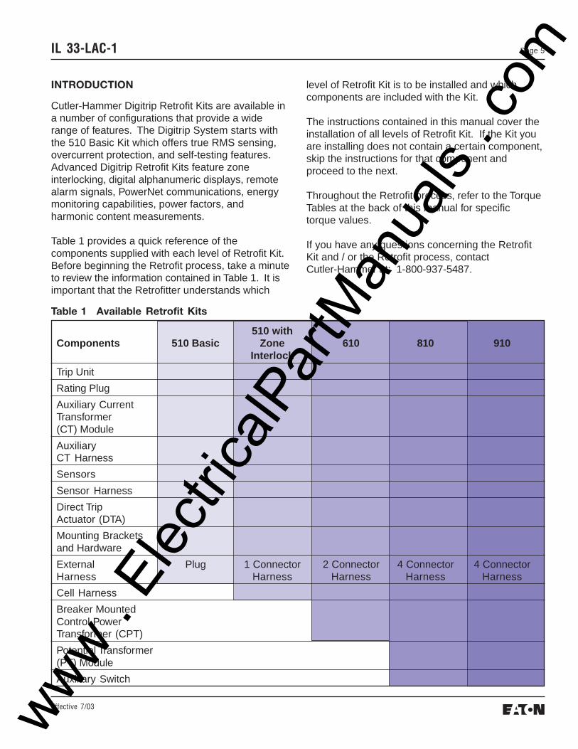
Cutler-Hammer Digitrip Retrofit Kits are available ina number of configurations that provide a widerange of features. The Digitrip System starts withthe 510 Basic Kit which offers true RMS sensing,overcurrent protection, and self-testing features.Advanced Digitrip Retrofit Kits feature zoneinterlocking, digital alphanumeric displays, remotealarm signals, PowerNet communications, energymonitoring capabilities, power factors, andharmonic content measurements.
Table 1 provides a quick reference of thecomponents supplied with each level of Retrofit Kit.Before beginning the Retrofit process, take a minuteto review the information contained in Table 1. It isimportant that the Retrofitter understands which
level of Retrofit Kit is to be installed and whichcomponents are included with the Kit.
The instructions contained in this manual cover theinstallation of all levels of Retrofit Kit. If the Kit youare installing does not contain a certain component,skip the instructions for that component andproceed to the next.
Throughout the Retrofit process, refer to the TorqueTables at the back of this manual for specifictorque values.
If you have any questions concerning the RetrofitKit and / or the Retrofit process, contactCutler-Hammer at: 1-800-937-5487.
Before attempting to remove the Breaker from theCell or perform any Retrofit Operation, be sure toread and understand the Safety Precautionssection of this manual. In addition, be sure toread and understand the Instructions for theApplication of Digitrip RMS Retrofit Kits on PowerCircuit Breakers (Retrofit Application Data -Publication AD 33-855-4), supplied with theDigitrip Retrofit Kit.
WARNING
DO NOT ATTEMPT TO INSTALL OR PERFORMMAINTENANCE ON EQUIPMENT WHILE IT ISENERGIZED. SEVERE PERSONAL INJURY ORDEATH CAN RESULT FROM CONTACT WITHENERGIZED EQUIPMENT. VERIFY THAT NOVOLTAGE IS PRESENT BEFORE PROCEEDING.
A. Trip the Breaker and remove it from the Cell.Move the Breaker to a clean, well-lit work area.
NOTE: It is the responsibility of the Retrofitter toinsure that the Breaker and all originalcomponents are in good condition.Visually inspect all Breaker componentsfor signs of damage or wear. If any signsof damage or wear are detected forcomponents not included in the RetrofitKit, secure the necessary replacementparts before beginning the Retrofit Pro-cess.
The force necessary to trip the Breakershould not exceed seven and a quarter(7.25) lbs.
NOTE: It is the responsibility of the Retrofitter toinsure that the proper, manufacturer’srecommended crimping tools and termi-nals are used for each type of connector.It is also the responsibility of theRetrofitter to insure that all wire prepara-tions, connections, strippings, termina-tions, and wiring techniques are per-formed according to the latest IEEE,NEC, and / or NEMA industry standards,specifications, codes, and guidelines.
To begin the Retrofit Process, refer to thecomponents list at the end of this manual.Layout the components and hardware accord-ing to the steps outlined. The parts bags arelabeled with the corresponding step number.The components and hardware will be used tocomplete each step in the Retrofit Process.
www . El
ectric
alPar
tMan
uals
. com
Effective 7/03
Page 7IL 33-LAC-1
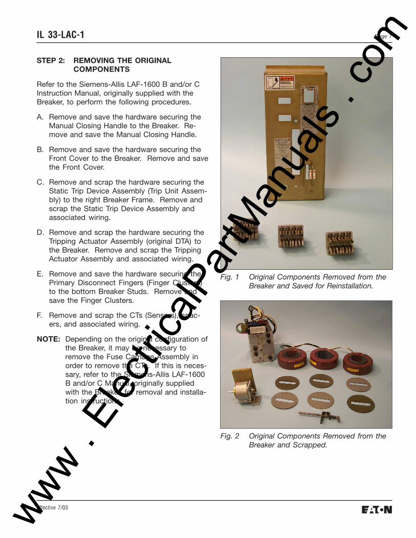
STEP 2: REMOVING THE ORIGINALCOMPONENTS
Refer to the Siemens-Allis LAF-1600 B and/or CInstruction Manual, originally supplied with theBreaker, to perform the following procedures.
A. Remove and save the hardware securing theManual Closing Handle to the Breaker. Re-move and save the Manual Closing Handle.
B. Remove and save the hardware securing theFront Cover to the Breaker. Remove and savethe Front Cover.
C. Remove and scrap the hardware securing theStatic Trip Device Assembly (Trip Unit Assem-bly) to the right Breaker Frame. Remove andscrap the Static Trip Device Assembly andassociated wiring.
D. Remove and scrap the hardware securing theTripping Actuator Assembly (original DTA) tothe Breaker. Remove and scrap the TrippingActuator Assembly and associated wiring.
E. Remove and save the hardware securing thePrimary Disconnect Fingers (Finger Clusters)to the bottom Breaker Studs. Remove andsave the Finger Clusters.
F. Remove and scrap the CTs (Sensors), spac-ers, and associated wiring.
NOTE: Depending on the original configuration ofthe Breaker, it may be necessary toremove the Fuse Carriage Assembly inorder to remove the CTs. If this is neces-sary, refer to the Siemens-Allis LAF-1600B and/or C Manual, originally suppliedwith the Breaker, for removal and installa-tion instructions.
Fig. 1 Original Components Removed from theBreaker and Saved for Reinstallation.
Fig. 2 Original Components Removed from theBreaker and Scrapped.
www . El
ectric
alPar
tMan
uals
. com
Effective 7/03
IL 33-LAC-1Page 8
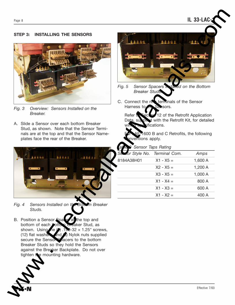
STEP 3: INSTALLING THE SENSORS
Fig. 3 Overview: Sensors Installed on theBreaker.
A. Slide a Sensor over each bottom BreakerStud, as shown. Note that the Sensor Termi-nals are at the top and that the Sensor Name-plates face the rear of the Breaker.
Fig. 5 Sensor Spacers Installed on the BottomBreaker Studs.
C. Connect the ring terminals of the SensorHarness to the Sensors.
Refer to Section 12 of the Retrofit ApplicationData, supplied with the Retrofit Kit, for detailedwiring specifications.
For LAF-1600 B and C Retrofits, the followingconventions apply.
Table 2 Sensor Taps Rating
Sensor Style No. Terminal Com. Amps
8184A38H01 X1 - X5 = 1,600 A
X2 - X5 = 1,200 A
X3 - X5 = 1,000 A
X1 - X4 = 800 A
X1 - X3 = 600 A
X1 - X2 = 400 A
Fig. 4 Sensors Installed on the Bottom BreakerStuds.
B. Position a Sensor Spacer at the top andbottom of each bottom Breaker Stud, asshown. Using the (6) .190-32 × 1.25" screws,(12) flat washers, and (6) Nylok nuts suppliedsecure the Sensor Spacers to the bottomBreaker Studs so they hold the Sensorsagainst the Breaker Backplate. Do not overtighten the mounting hardware.
www . El
ectric
alPar
tMan
uals
. com
Effective 7/03
Page 9IL 33-LAC-1
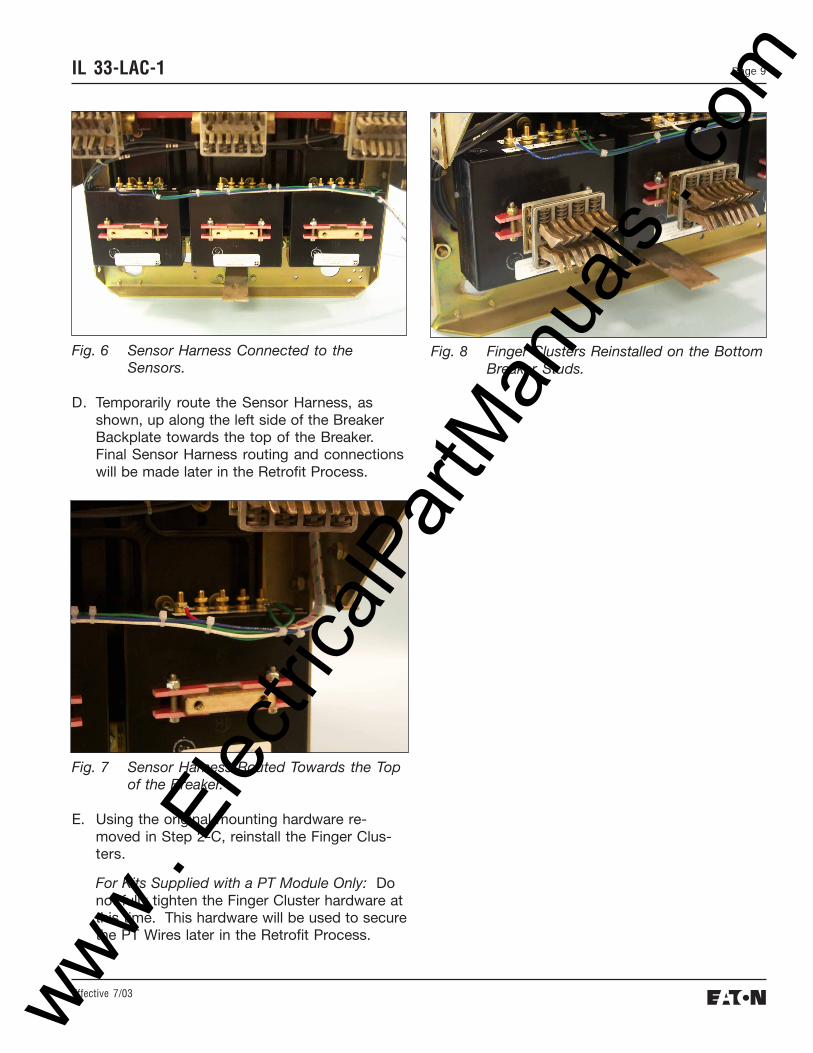
Fig. 6 Sensor Harness Connected to theSensors.
D. Temporarily route the Sensor Harness, asshown, up along the left side of the BreakerBackplate towards the top of the Breaker.Final Sensor Harness routing and connectionswill be made later in the Retrofit Process.
Fig. 7 Sensor Harness Routed Towards the Topof the Breaker.
E. Using the original mounting hardware re-moved in Step 2-C, reinstall the Finger Clus-ters.
For Kits Supplied with a PT Module Only: Donot fully tighten the Finger Cluster hardware atthis time. This hardware will be used to securethe PT Wires later in the Retrofit Process.
Fig. 8 Finger Clusters Reinstalled on the BottomBreaker Studs.
www . El
ectric
alPar
tMan
uals
. com
Effective 7/03
IL 33-LAC-1Page 10
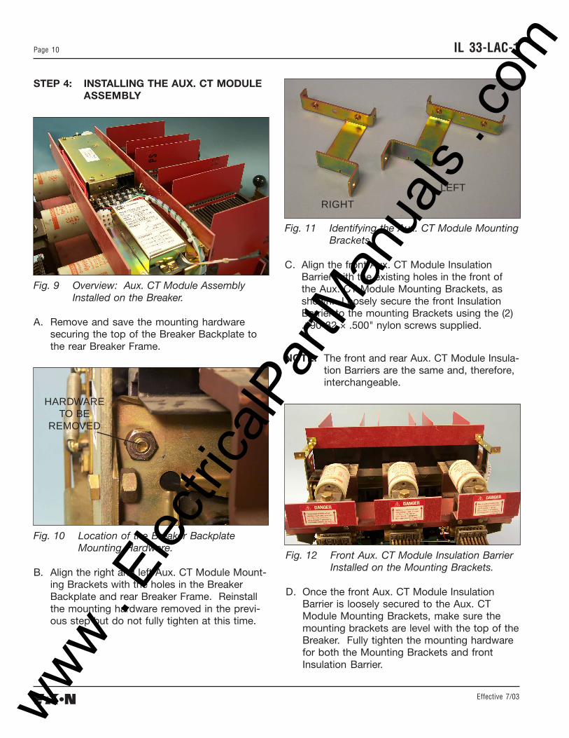
STEP 4: INSTALLING THE AUX. CT MODULEASSEMBLY
Fig. 9 Overview: Aux. CT Module AssemblyInstalled on the Breaker.
A. Remove and save the mounting hardwaresecuring the top of the Breaker Backplate tothe rear Breaker Frame.
Fig. 11 Identifying the Aux. CT Module MountingBrackets.
C. Align the front Aux. CT Module InsulationBarrier with the existing holes in the front ofthe Aux. CT Module Mounting Brackets, asshown. Loosely secure the front InsulationBarrier to the mounting Brackets using the (2).190-32 × .500" nylon screws supplied.
NOTE: The front and rear Aux. CT Module Insula-tion Barriers are the same and, therefore,interchangeable.
Fig. 10 Location of the Breaker BackplateMounting Hardware.
B. Align the right and left Aux. CT Module Mount-ing Brackets with the holes in the BreakerBackplate and rear Breaker Frame. Reinstallthe mounting hardware removed in the previ-ous step but do not fully tighten at this time.
HARDWARETO BE
REMOVED
RIGHT
LEFT
Fig. 12 Front Aux. CT Module Insulation BarrierInstalled on the Mounting Brackets.
D. Once the front Aux. CT Module InsulationBarrier is loosely secured to the Aux. CTModule Mounting Brackets, make sure themounting brackets are level with the top of theBreaker. Fully tighten the mounting hardwarefor both the Mounting Brackets and frontInsulation Barrier.
www . El
ectric
alPar
tMan
uals
. com
Effective 7/03
Page 11IL 33-LAC-1
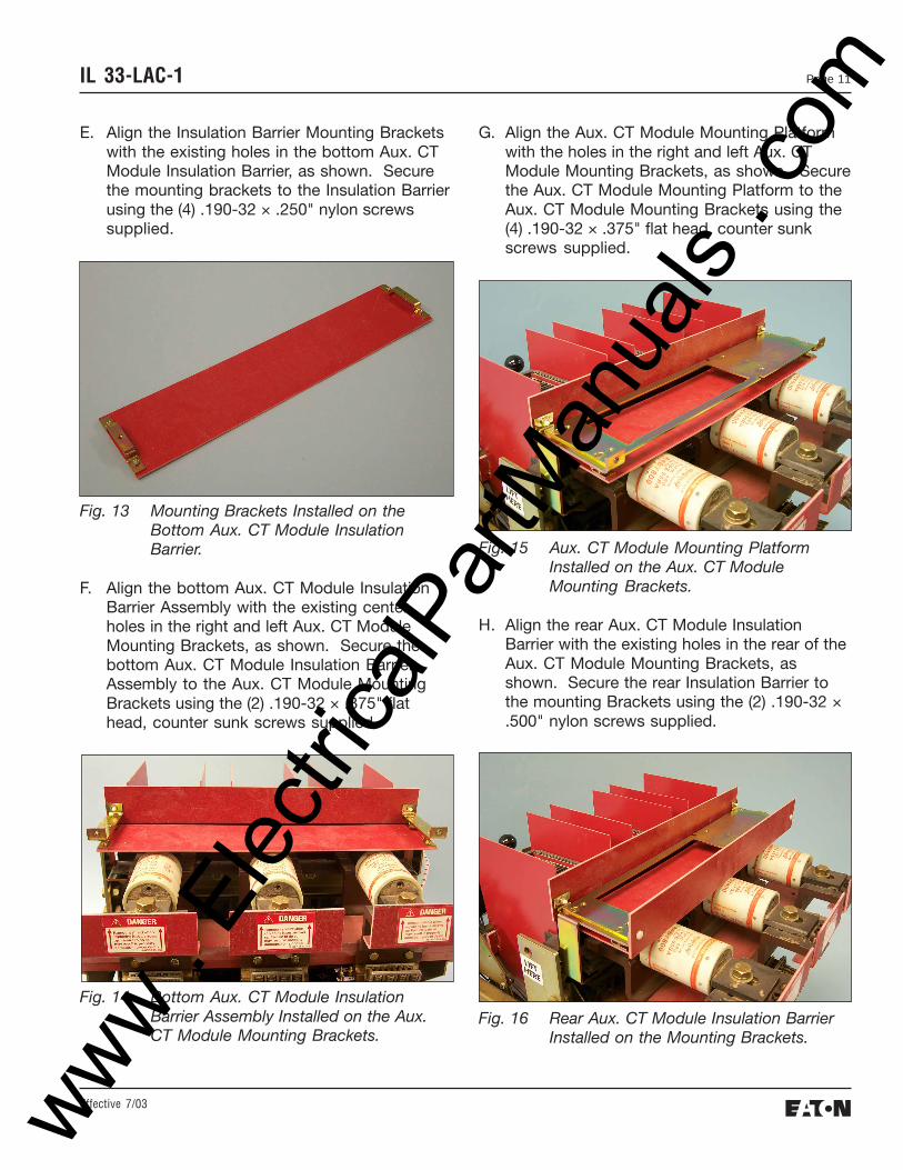
E. Align the Insulation Barrier Mounting Bracketswith the existing holes in the bottom Aux. CTModule Insulation Barrier, as shown. Securethe mounting brackets to the Insulation Barrierusing the (4) .190-32 × .250" nylon screwssupplied.
G. Align the Aux. CT Module Mounting Platformwith the holes in the right and left Aux. CTModule Mounting Brackets, as shown. Securethe Aux. CT Module Mounting Platform to theAux. CT Module Mounting Brackets using the(4) .190-32 × .375" flat head, counter sunkscrews supplied.
F. Align the bottom Aux. CT Module InsulationBarrier Assembly with the existing centerholes in the right and left Aux. CT ModuleMounting Brackets, as shown. Secure thebottom Aux. CT Module Insulation BarrierAssembly to the Aux. CT Module MountingBrackets using the (2) .190-32 × .375" flathead, counter sunk screws supplied.
Fig. 14 Bottom Aux. CT Module InsulationBarrier Assembly Installed on the Aux.CT Module Mounting Brackets.
Fig. 15 Aux. CT Module Mounting PlatformInstalled on the Aux. CT ModuleMounting Brackets.
H. Align the rear Aux. CT Module InsulationBarrier with the existing holes in the rear of theAux. CT Module Mounting Brackets, asshown. Secure the rear Insulation Barrier tothe mounting Brackets using the (2) .190-32 ×.500" nylon screws supplied.
Fig. 16 Rear Aux. CT Module Insulation BarrierInstalled on the Mounting Brackets.
www . El
ectric
alPar
tMan
uals
. com
Effective 7/03
IL 33-LAC-1Page 12
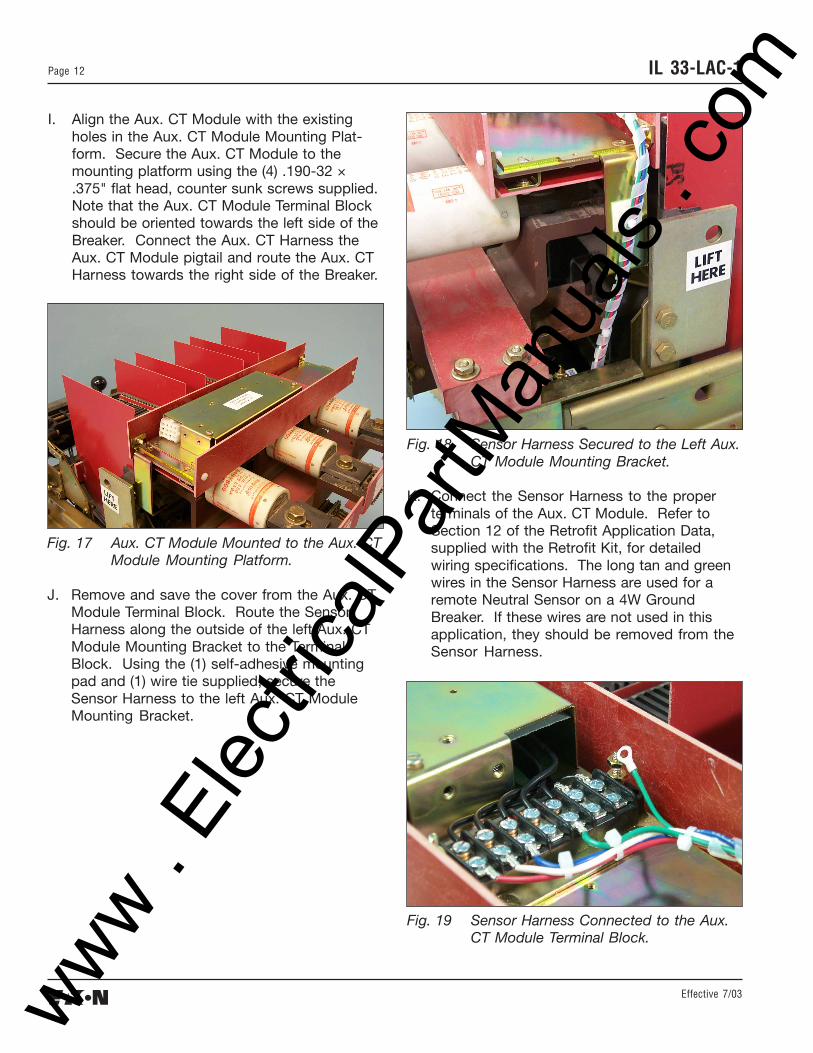
I. Align the Aux. CT Module with the existingholes in the Aux. CT Module Mounting Plat-form. Secure the Aux. CT Module to themounting platform using the (4) .190-32 ×.375" flat head, counter sunk screws supplied.Note that the Aux. CT Module Terminal Blockshould be oriented towards the left side of theBreaker. Connect the Aux. CT Harness theAux. CT Module pigtail and route the Aux. CTHarness towards the right side of the Breaker.
Fig. 17 Aux. CT Module Mounted to the Aux. CTModule Mounting Platform.
J. Remove and save the cover from the Aux. CTModule Terminal Block. Route the SensorHarness along the outside of the left Aux. CTModule Mounting Bracket to the TerminalBlock. Using the (1) self-adhesive mountingpad and (1) wire tie supplied, secure theSensor Harness to the left Aux. CT ModuleMounting Bracket.
Fig. 18 Sensor Harness Secured to the Left Aux.CT Module Mounting Bracket.
K. Connect the Sensor Harness to the properterminals of the Aux. CT Module. Refer toSection 12 of the Retrofit Application Data,supplied with the Retrofit Kit, for detailedwiring specifications. The long tan and greenwires in the Sensor Harness are used for aremote Neutral Sensor on a 4W GroundBreaker. If these wires are not used in thisapplication, they should be removed from theSensor Harness.
Fig. 19 Sensor Harness Connected to the Aux.CT Module Terminal Block.
www . El
ectric
alPar
tMan
uals
. com
Effective 7/03
Page 13IL 33-LAC-1
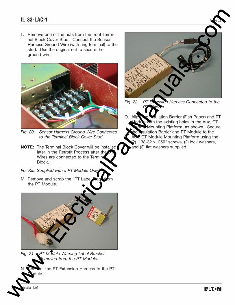
L. Remove one of the nuts from the front Termi-nal Block Cover Stud. Connect the SensorHarness Ground Wire (with ring terminal) to thestud. Use the original nut to secure theground wire.
Fig. 21 PT Module Warning Label BracketRemoved from the PT Module.
N. Connect the PT Extension Harness to the PTModule.
NOTE: The Terminal Block Cover will be installedlater in the Retrofit Process after the DTAWires are connected to the TerminalBlock.
For Kits Supplied with a PT Module Only.
M. Remove and scrap the “PT Label Flag” fromthe PT Module.
Fig. 22 PT Extension Harness Connected to thePT Module.
O. Align the Insulation Barrier (Fish Paper) and PTModule with the existing holes in the Aux. CTModule Mounting Platform, as shown. Securethe Insulation Barrier and PT Module to theAux. CT Module Mounting Platform using the(2) .138-32 × .250" screws, (2) lock washers,and (2) flat washers supplied.
www . El
ectric
alPar
tMan
uals
. com
Effective 7/03
IL 33-LAC-1Page 14
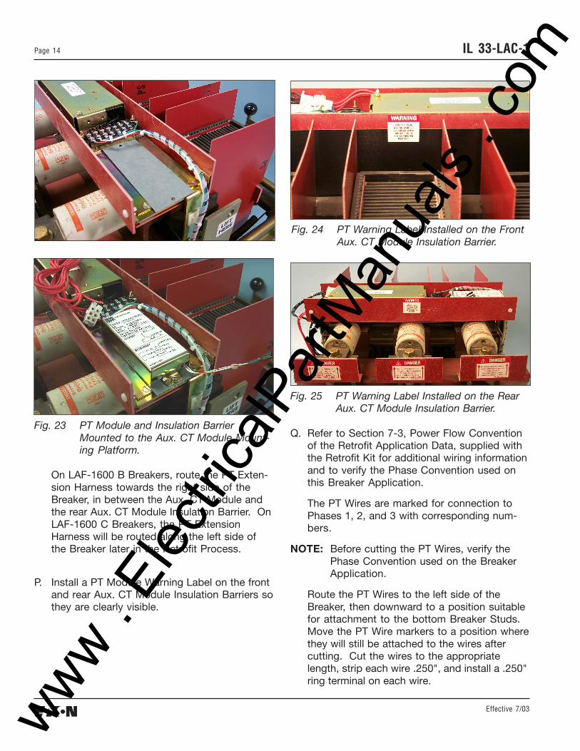
Fig. 24 PT Warning Label Installed on the FrontAux. CT Module Insulation Barrier.
Fig. 23 PT Module and Insulation BarrierMounted to the Aux. CT Module Mount-ing Platform.
On LAF-1600 B Breakers, route the PT Exten-sion Harness towards the right side of theBreaker, in between the Aux. CT Module andthe rear Aux. CT Module Insulation Barrier. OnLAF-1600 C Breakers, the PT ExtensionHarness will be routed along the left side ofthe Breaker later in the Retrofit Process.
P. Install a PT Module Warning Label on the frontand rear Aux. CT Module Insulation Barriers sothey are clearly visible.
Fig. 25 PT Warning Label Installed on the RearAux. CT Module Insulation Barrier.
Q. Refer to Section 7-3, Power Flow Conventionof the Retrofit Application Data, supplied withthe Retrofit Kit for additional wiring informationand to verify the Phase Convention used onthis Breaker Application.
The PT Wires are marked for connection toPhases 1, 2, and 3 with corresponding num-bers.
NOTE: Before cutting the PT Wires, verify thePhase Convention used on the BreakerApplication.
Route the PT Wires to the left side of theBreaker, then downward to a position suitablefor attachment to the bottom Breaker Studs.Move the PT Wire markers to a position wherethey will still be attached to the wires aftercutting. Cut the wires to the appropriatelength, strip each wire .250", and install a .250"ring terminal on each wire.
www . El
ectric
alPar
tMan
uals
. com
Effective 7/03
Page 15IL 33-LAC-1
STEP 5: INSTALLING THE DTA ASSEMBLY
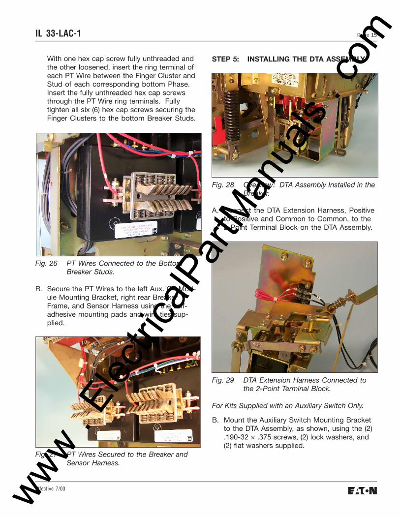
Fig. 28 Overview: DTA Assembly Installed in theBreaker.
A. Connect the DTA Extension Harness, Positiveto Positive and Common to Common, to the2-Point Terminal Block on the DTA Assembly.
B. Mount the Auxiliary Switch Mounting Bracketto the DTA Assembly, as shown, using the (2).190-32 × .375 screws, (2) lock washers, and(2) flat washers supplied.
With one hex cap screw fully unthreaded andthe other loosened, insert the ring terminal ofeach PT Wire between the Finger Cluster andStud of each corresponding bottom Phase.Insert the fully unthreaded hex cap screwsthrough the PT Wire ring terminals. Fullytighten all six (6) hex cap screws securing theFinger Clusters to the bottom Breaker Studs.
Fig. 26 PT Wires Connected to the BottomBreaker Studs.
R. Secure the PT Wires to the left Aux. CT Mod-ule Mounting Bracket, right rear BreakerFrame, and Sensor Harness using the self-adhesive mounting pads and wire ties sup-plied.
Fig. 27 PT Wires Secured to the Breaker andSensor Harness.
www . El
ectric
alPar
tMan
uals
. com
Effective 7/03
IL 33-LAC-1Page 16
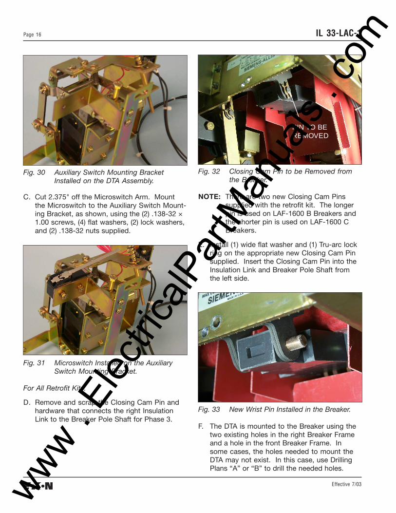
Fig. 30 Auxiliary Switch Mounting BracketInstalled on the DTA Assembly.
C. Cut 2.375" off the Microswitch Arm. Mountthe Microswitch to the Auxiliary Switch Mount-ing Bracket, as shown, using the (2) .138-32 ×1.00 screws, (4) flat washers, (2) lock washers,and (2) .138-32 nuts supplied.
Fig. 32 Closing Cam Pin to be Removed fromthe Breaker.
NOTE: There are two new Closing Cam Pinssupplied with the retrofit kit. The longerpin is used on LAF-1600 B Breakers andthe shorter pin is used on LAF-1600 CBreakers.
E. Install (1) wide flat washer and (1) Tru-arc lockring on the appropriate new Closing Cam Pinsupplied. Insert the Closing Cam Pin into theInsulation Link and Breaker Pole Shaft fromthe left side.
Fig. 31 Microswitch Installed on the AuxiliarySwitch Mounting Bracket.
For All Retrofit Kits.
D. Remove and scrap the Closing Cam Pin andhardware that connects the right InsulationLink to the Breaker Pole Shaft for Phase 3.
PIN TO BEREMOVED
Fig. 33 New Wrist Pin Installed in the Breaker.
F. The DTA is mounted to the Breaker using thetwo existing holes in the right Breaker Frameand a hole in the front Breaker Frame. Insome cases, the holes needed to mount theDTA may not exist. In this case, use DrillingPlans “A” or “B” to drill the needed holes.
www . El
ectric
alPar
tMan
uals
. com
Effective 7/03
Page 17IL 33-LAC-1
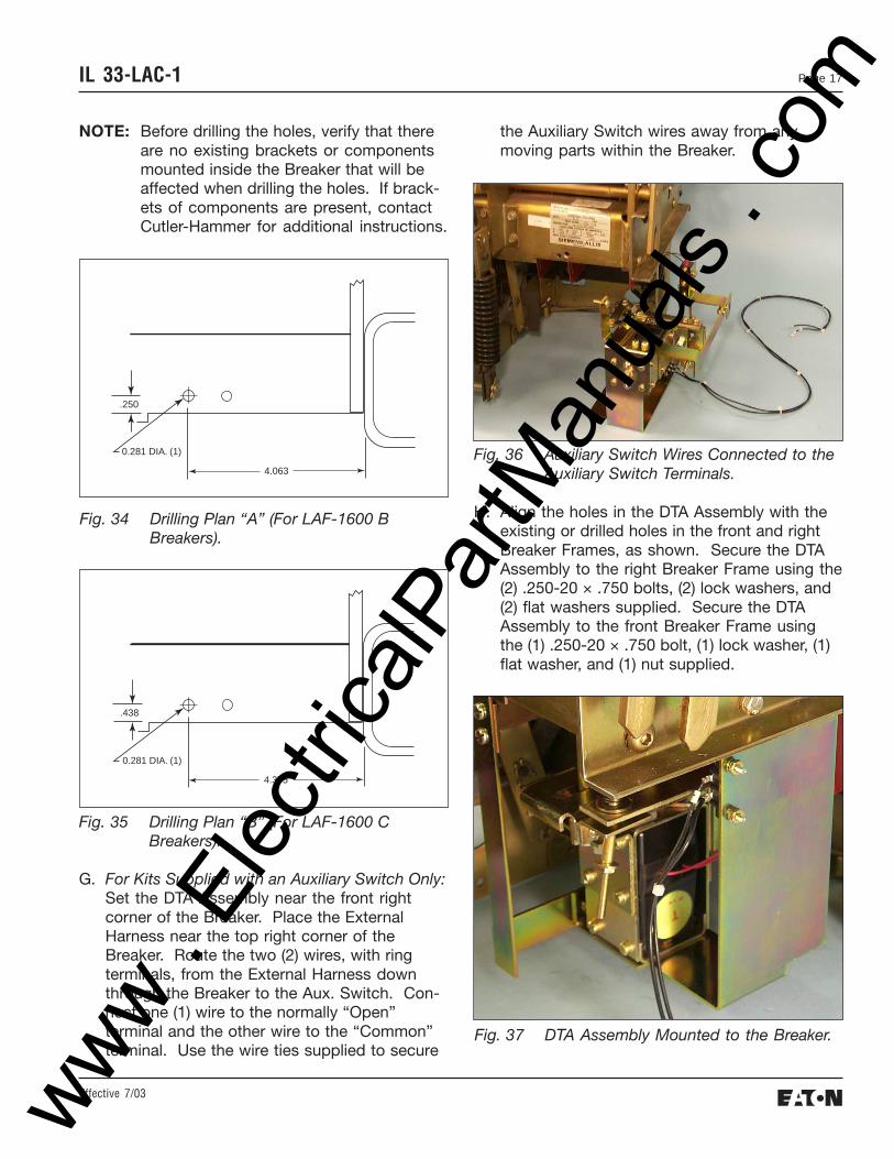
NOTE: Before drilling the holes, verify that thereare no existing brackets or componentsmounted inside the Breaker that will beaffected when drilling the holes. If brack-ets of components are present, contactCutler-Hammer for additional instructions.
the Auxiliary Switch wires away from anymoving parts within the Breaker.
.250
0.281 DIA. (1)
4.063
Fig. 34 Drilling Plan “A” (For LAF-1600 BBreakers).
Fig. 35 Drilling Plan “B” (For LAF-1600 CBreakers).
G. For Kits Supplied with an Auxiliary Switch Only:Set the DTA Assembly near the front rightcorner of the Breaker. Place the ExternalHarness near the top right corner of theBreaker. Route the two (2) wires, with ringterminals, from the External Harness downthrough the Breaker to the Aux. Switch. Con-nect one (1) wire to the normally “Open”terminal and the other wire to the “Common”terminal. Use the wire ties supplied to secure
.438
0.281 DIA. (1)
4.375
Fig. 36 Auxiliary Switch Wires Connected to theAuxiliary Switch Terminals.
H. Align the holes in the DTA Assembly with theexisting or drilled holes in the front and rightBreaker Frames, as shown. Secure the DTAAssembly to the right Breaker Frame using the(2) .250-20 × .750 bolts, (2) lock washers, and(2) flat washers supplied. Secure the DTAAssembly to the front Breaker Frame usingthe (1) .250-20 × .750 bolt, (1) lock washer, (1)flat washer, and (1) nut supplied.
Fig. 37 DTA Assembly Mounted to the Breaker.
www . El
ectric
alPar
tMan
uals
. com
Effective 7/03
IL 33-LAC-1Page 18
NOTE: When installing the Reset Assembly onthe Closing Cam Pin, different configura-tions of wide flat washers is needed forthe LAF-1600 B and C Breakers.
For the LAF-1600 B Breaker, four (4) wideflat washers are used between the Clos-ing Cam and Reset Assembly to spacethe Reset Assembly away from theClosing Cam. The Tru-arc lock ring isused to secure the Reset Assembly onthe Closing Cam Pin.
For the LAF-1600 C Breaker, no wide flatwashers are used between the ClosingCam and Reset Assembly. One (1) wideflat washers and the Tru-arc lock ring areused to secure the Reset Assembly onthe Closing Cam Pin.
I. While holding the Closing Cam Pin in place,push the Reset Assembly downward tocompress the Reset Spring until the hole in theReset Assembly aligns with the Closing CamPin. Slide the Reset Assembly and applicablewide flat washers (see Note above) onto theClosing Cam Pin. Install (1) Tru-arc lock ringon the wrist pin to secure the Reset Assemblyon the Closing Cam Pin.
NOTE: It may be necessary to loosen the nutson the Reset Shaft to allow the ResetAssembly to be installed on the ClosingCam Pin.
Fig. 39 Reset Assembly Mounting on aLAF-1600 C Breaker.
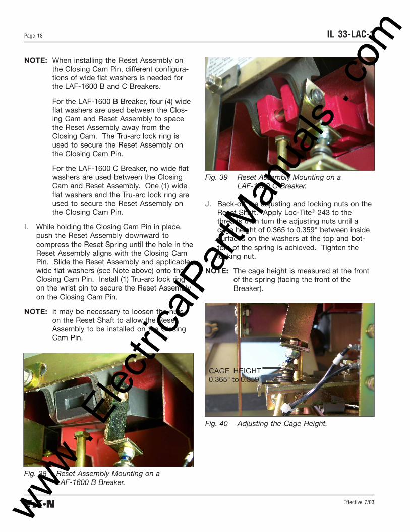
J. Back-off the adjusting and locking nuts on theReset Shaft. Apply Loc-Tite® 243 to thethreads then turn the adjusting nuts until acage height of 0.365 to 0.359" between insidesurfaces on the washers at the top and bot-tom of the spring is achieved. Tighten thelocking nut.
NOTE: The cage height is measured at the frontof the spring (facing the front of theBreaker).
Fig. 38 Reset Assembly Mounting on aLAF-1600 B Breaker.
Fig. 40 Adjusting the Cage Height.
CAGE HEIGHT0.365" to 0.359"
www . El
ectric
alPar
tMan
uals
. com
Effective 7/03
Page 19IL 33-LAC-1
WARNING:
TO ADJUST THE GAP BETWEEN THE DTAADJUSTING SCREW AND BREAK TRIPPADDLE, THE BREAKER MUST BE IN THECLOSED POSITION. KEEP HANDS AND FIN-GERS AWAY FROM MOVING PARTS WITHINTHE BREAKER. FAILURE TO DO SO COULDRESULT IN SEVERE PERSONAL INJURY.
K. Temporarily reinstall the Charging Handle onthe Breaker.
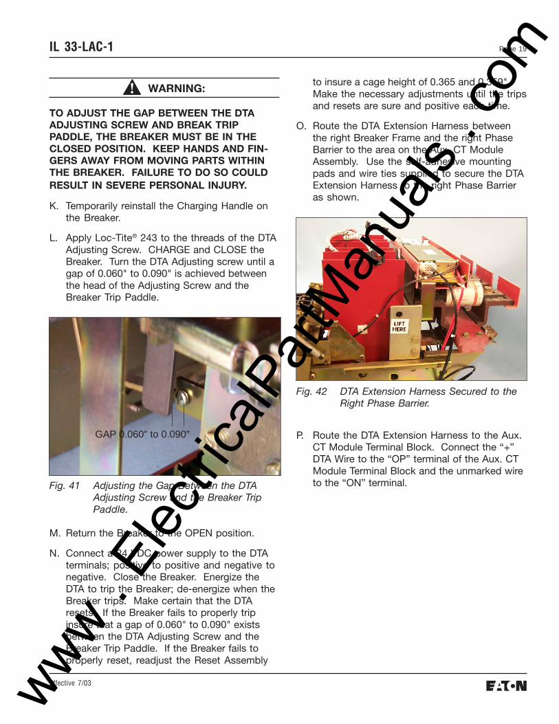
L. Apply Loc-Tite® 243 to the threads of the DTAAdjusting Screw. CHARGE and CLOSE theBreaker. Turn the DTA Adjusting screw until agap of 0.060" to 0.090" is achieved betweenthe head of the Adjusting Screw and theBreaker Trip Paddle.
to insure a cage height of 0.365 and 0.359".Make the necessary adjustments until the tripsand resets are sure and positive each time.
O. Route the DTA Extension Harness betweenthe right Breaker Frame and the right PhaseBarrier to the area on the Aux. CT ModuleAssembly. Use the self-adhesive mountingpads and wire ties supplied to secure the DTAExtension Harness to the right Phase Barrieras shown.
Fig. 41 Adjusting the Gap Between the DTAAdjusting Screw and the Breaker TripPaddle.
M. Return the Breaker to the OPEN position.
N. Connect a 24 VDC power supply to the DTAterminals; positive to positive and negative tonegative. Close the Breaker. Energize theDTA to trip the Breaker; de-energize when theBreaker trips. Make certain that the DTAresets. If the Breaker fails to properly tripinsure that a gap of 0.060" to 0.090" existsbetween the DTA Adjusting Screw and theBreaker Trip Paddle. If the Breaker fails toproperly reset, readjust the Reset Assembly
Fig. 42 DTA Extension Harness Secured to theRight Phase Barrier.
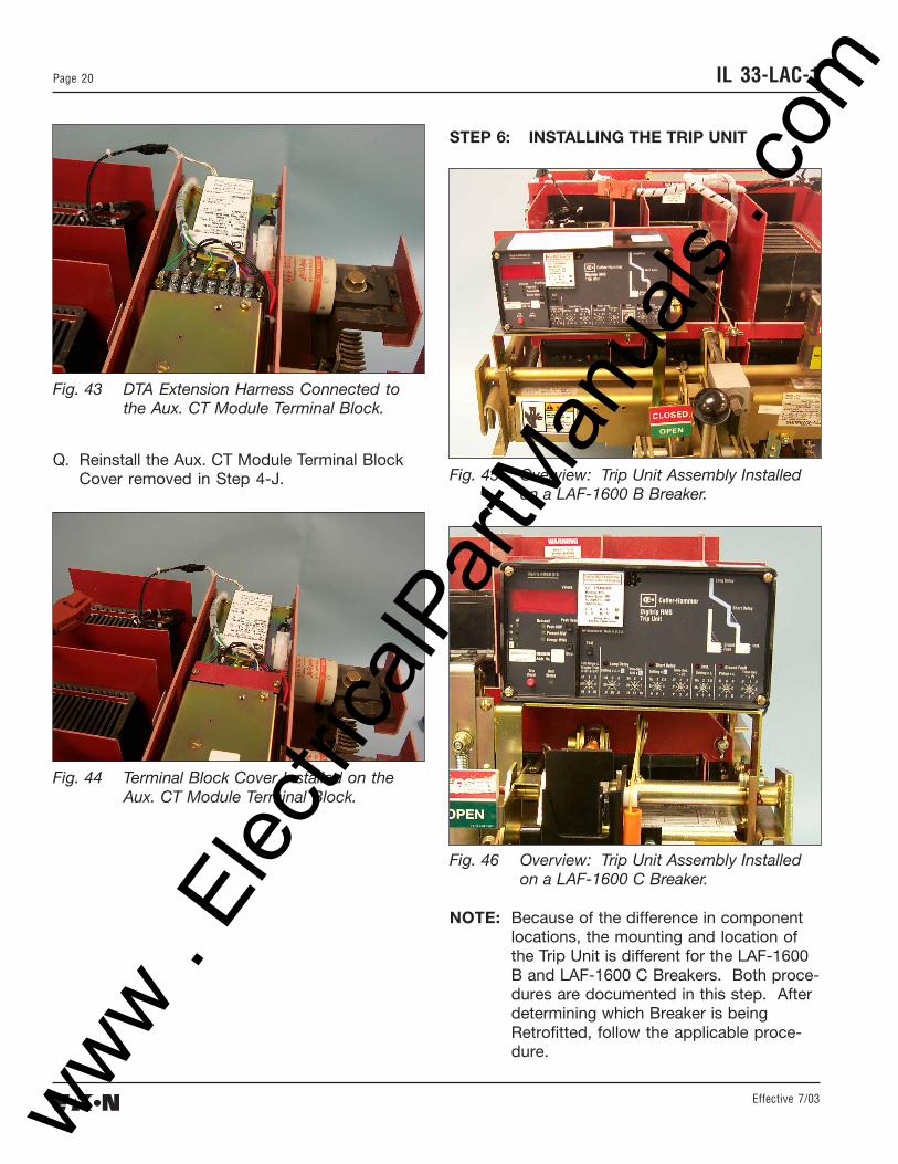
P. Route the DTA Extension Harness to the Aux.CT Module Terminal Block. Connect the “+”DTA Wire to the “OP” terminal of the Aux. CTModule Terminal Block and the unmarked wireto the “ON” terminal.
Fig. 45 Overview: Trip Unit Assembly Installedon a LAF-1600 B Breaker.
Fig. 46 Overview: Trip Unit Assembly Installedon a LAF-1600 C Breaker.
NOTE: Because of the difference in componentlocations, the mounting and location ofthe Trip Unit is different for the LAF-1600B and LAF-1600 C Breakers. Both proce-dures are documented in this step. Afterdetermining which Breaker is beingRetrofitted, follow the applicable proce-dure.
www . El
ectric
alPar
tMan
uals
. com
Effective 7/03
Page 21IL 33-LAC-1
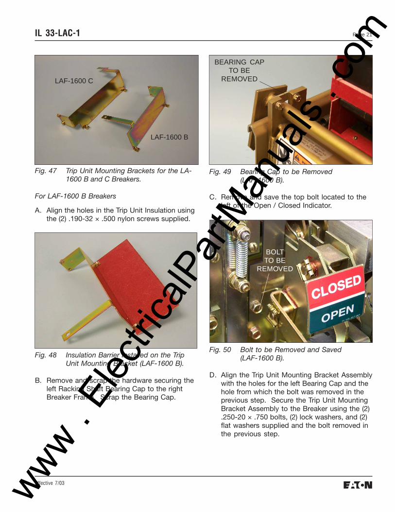
Fig. 47 Trip Unit Mounting Brackets for the LA-1600 B and C Breakers.
For LAF-1600 B Breakers
A. Align the holes in the Trip Unit Insulation usingthe (2) .190-32 × .500 nylon screws supplied.
Fig. 49 Bearing Cap to be Removed(LAF-1600 B).
C. Remove and save the top bolt located to theleft of the Open / Closed Indicator.
LAF-1600 B
LAF-1600 C
Fig. 48 Insulation Barrier Installed on the TripUnit Mounting Bracket (LAF-1600 B).
B. Remove and scrap the hardware securing theleft Racking Shaft Bearing Cap to the rightBreaker Frame. Scrap the Bearing Cap.
BEARING CAPTO BE
REMOVED
Fig. 50 Bolt to be Removed and Saved(LAF-1600 B).
D. Align the Trip Unit Mounting Bracket Assemblywith the holes for the left Bearing Cap and thehole from which the bolt was removed in theprevious step. Secure the Trip Unit MountingBracket Assembly to the Breaker using the (2).250-20 × .750 bolts, (2) lock washers, and (2)flat washers supplied and the bolt removed inthe previous step.
BOLTTO BE
REMOVED
www . El
ectric
alPar
tMan
uals
. com
Effective 7/03
IL 33-LAC-1Page 22
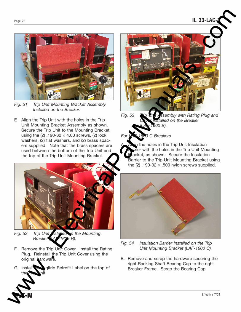
Fig. 51 Trip Unit Mounting Bracket AssemblyInstalled on the Breaker.
E Align the Trip Unit with the holes in the TripUnit Mounting Bracket Assembly as shown.Secure the Trip Unit to the Mounting Bracketusing the (2) .190-32 × 4.00 screws, (2) lockwashers, (2) flat washers, and (2) brass spac-ers supplied. Note that the brass spacers areused between the bottom of the Trip Unit andthe top of the Trip Unit Mounting Bracket.
Fig. 52 Trip Unit Installed on the MountingBracket (LAF-1600 B).
F. Remove the Trip Unit Cover. Install the RatingPlug. Reinstall the Trip Unit Cover using theoriginal hardware.
G. Install the Digitrip Retrofit Label on the top ofthe Trip Unit.
Fig. 53 Trip Unit Assembly with Rating Plug andCover Installed on the Breaker(LAF-1600 B).
For LAF-1600 C Breakers
A. Align the holes in the Trip Unit InsulationBarrier with the holes in the Trip Unit MountingBracket, as shown. Secure the InsulationBarrier to the Trip Unit Mounting Bracket usingthe (2) .190-32 × .500 nylon screws supplied.
Fig. 54 Insulation Barrier Installed on the TripUnit Mounting Bracket (LAF-1600 C).
B. Remove and scrap the hardware securing theright Racking Shaft Bearing Cap to the rightBreaker Frame. Scrap the Bearing Cap.
www . El
ectric
alPar
tMan
uals
. com
Effective 7/03
Page 23IL 33-LAC-1
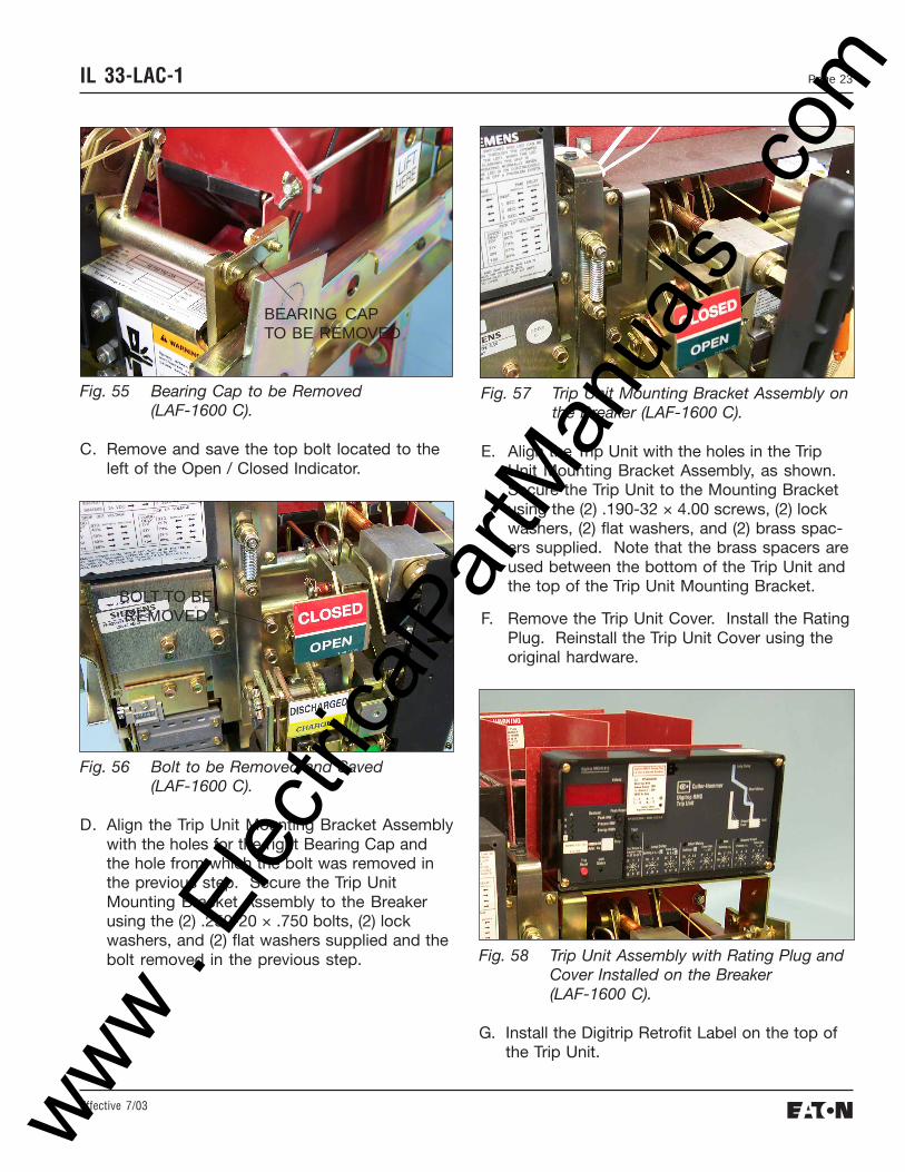
Fig. 55 Bearing Cap to be Removed(LAF-1600 C).
C. Remove and save the top bolt located to theleft of the Open / Closed Indicator.
Fig. 56 Bolt to be Removed and Saved(LAF-1600 C).
D. Align the Trip Unit Mounting Bracket Assemblywith the holes for the right Bearing Cap andthe hole from which the bolt was removed inthe previous step. Secure the Trip UnitMounting Bracket Assembly to the Breakerusing the (2) .250-20 × .750 bolts, (2) lockwashers, and (2) flat washers supplied and thebolt removed in the previous step.
E. Align the Trip Unit with the holes in the TripUnit Mounting Bracket Assembly, as shown.Secure the Trip Unit to the Mounting Bracketusing the (2) .190-32 × 4.00 screws, (2) lockwashers, (2) flat washers, and (2) brass spac-ers supplied. Note that the brass spacers areused between the bottom of the Trip Unit andthe top of the Trip Unit Mounting Bracket.
F. Remove the Trip Unit Cover. Install the RatingPlug. Reinstall the Trip Unit Cover using theoriginal hardware.
BEARING CAPTO BE REMOVED
BOLT TO BEREMOVED
Fig. 58 Trip Unit Assembly with Rating Plug andCover Installed on the Breaker(LAF-1600 C).
G. Install the Digitrip Retrofit Label on the top ofthe Trip Unit.
www . El
ectric
alPar
tMan
uals
. com
Effective 7/03
IL 33-LAC-1Page 24
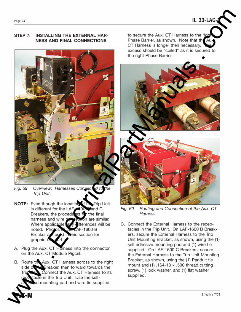
STEP 7: INSTALLING THE EXTERNAL HAR-NESS AND FINAL CONNECTIONS
Fig. 59 Overview: Harnesses Connected to theTrip Unit.
NOTE: Even though the location of the Trip Unitis different for the LAF-1600 B and CBreakers, the procedures for the finalharness and wire connection are similar.Where applicable, any differences will benoted. Photos of the LAF-1600 BBreaker are used in this section forgraphic support.
A. Plug the Aux. CT Harness into the connectoron the Aux. CT Module Pigtail.
B. Route the Aux. CT Harness across to the rightside of the Breaker, then forward towards theTrip Unit. Connect the Aux. CT Harness to itsreceptacle in the Trip Unit. Use the self-adhesive mounting pad and wire tie supplied
Fig. 60 Routing and Connection of the Aux. CTHarness.
C. Connect the External Harness to the recep-tacles in the Trip Unit. On LAF-1600 B Break-ers, secure the External Harness to the TripUnit Mounting Bracket, as shown, using the (1)self adhesive mounting pad and (1) wire tiesupplied. On LAF-1600 C Breakers, securethe External Harness to the Trip Unit MountingBracket, as shown, using the (1) Panduit tiemount and (1) .164-18 × .500 thread cuttingscrew, (1) lock washer, and (1) flat washersupplied.
to secure the Aux. CT Harness to the rightPhase Barrier, as shown. Note that the Aux.CT Harness is longer then necessary. Theexcess should be “coiled” as it is secured tothe right Phase Barrier.
www . El
ectric
alPar
tMan
uals
. com
Effective 7/03
Page 25IL 33-LAC-1
Fig. 62 External Harness Connected to the TripUnit (LAF-1600 C Breaker).
NOTE: For 510 Basic Kits, the External Harnessis the Shorting Plug pictured below. It isto be plugged into the correspondingreceptacle in the Trip Unit.
D. For Kits Supplied with a PT Module Only:Route the PT Extension Harness along the leftside (LAF-1600 B) or right side (LAF-1600 C) ofthe Breaker, then to the right side of the TripUnit. Connect the PT Extension to the corre-sponding plug on the External Harness. Usethe self-adhesive mounting pad and wire tiesupplied to secure the PT Extension Harnessto the outside Phase Barrier. Note that the PTExtension Harness is longer then necessary.The excess should be “coiled” as it is securedto the outside Phase Barrier.
Fig. 64 Connection of the PT Extension Harnessto the External Harness.
E For Kits Supplied with an Auxiliary Switch Only:Use the wire ties supplied to secure theAuxiliary Switch wires away from any movingparts within the Breaker.
F. Use the wire ties supplied to secure all wiresand harnesses away from any moving partswithin the Breaker.
Fig. 61 External Harness Connected to the TripUnit (LAF-1600 B Breaker).
www . El
ectric
alPar
tMan
uals
. com
Effective 7/03
IL 33-LAC-1Page 26
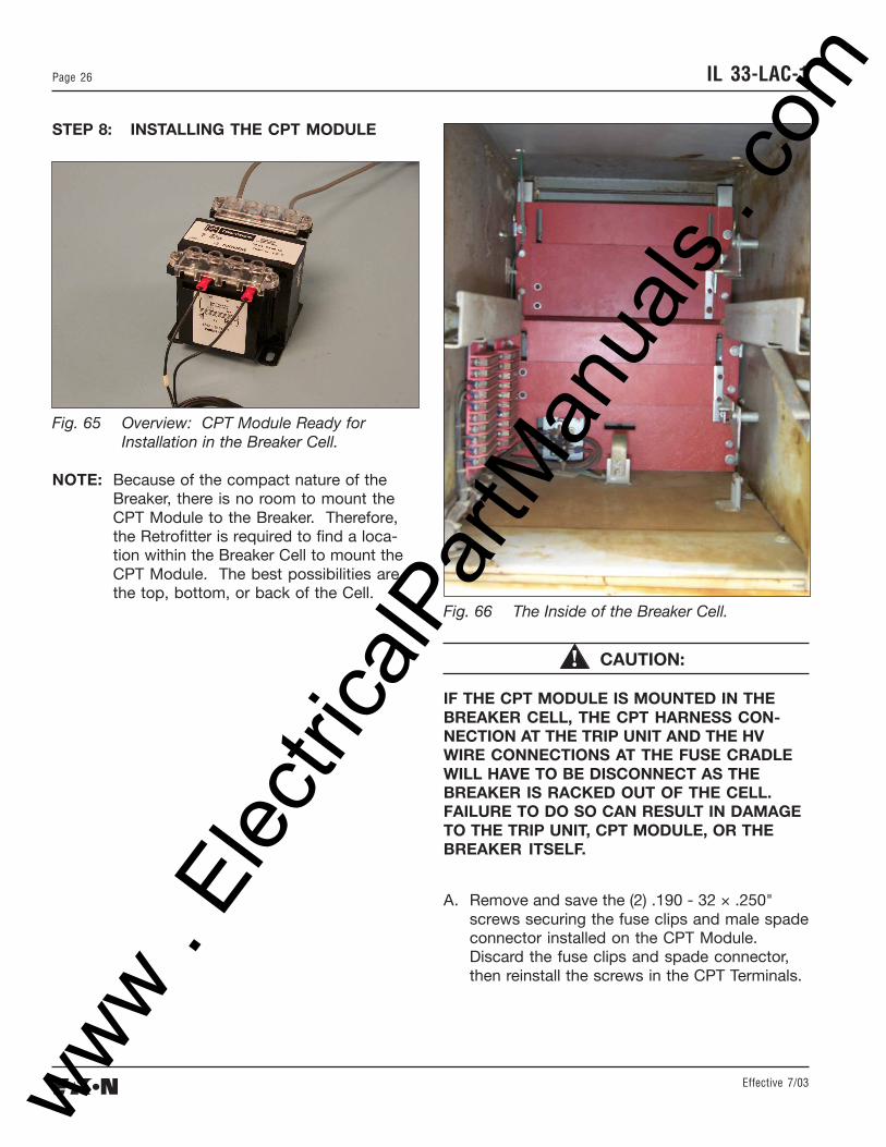
STEP 8: INSTALLING THE CPT MODULE
Fig. 65 Overview: CPT Module Ready forInstallation in the Breaker Cell.
NOTE: Because of the compact nature of theBreaker, there is no room to mount theCPT Module to the Breaker. Therefore,the Retrofitter is required to find a loca-tion within the Breaker Cell to mount theCPT Module. The best possibilities arethe top, bottom, or back of the Cell.
Fig. 66 The Inside of the Breaker Cell.
CAUTION:
IF THE CPT MODULE IS MOUNTED IN THEBREAKER CELL, THE CPT HARNESS CON-NECTION AT THE TRIP UNIT AND THE HVWIRE CONNECTIONS AT THE FUSE CRADLEWILL HAVE TO BE DISCONNECT AS THEBREAKER IS RACKED OUT OF THE CELL.FAILURE TO DO SO CAN RESULT IN DAMAGETO THE TRIP UNIT, CPT MODULE, OR THEBREAKER ITSELF.
A. Remove and save the (2) .190 - 32 × .250"screws securing the fuse clips and male spadeconnector installed on the CPT Module.Discard the fuse clips and spade connector,then reinstall the screws in the CPT Terminals.
www . El
ectric
alPar
tMan
uals
. com
Effective 7/03
Page 27IL 33-LAC-1
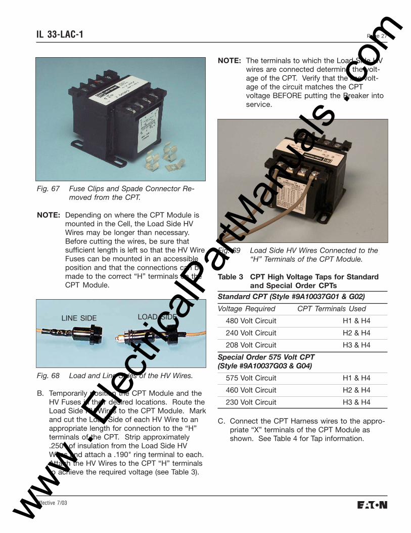
NOTE: The terminals to which the Load Side HVwires are connected determine the volt-age of the CPT. Verify that the line volt-age of the circuit matches the CPTvoltage BEFORE putting the Breaker intoservice.
Fig. 69 Load Side HV Wires Connected to the“H” Terminals of the CPT Module.
Table 3 CPT High Voltage Taps for Standardand Special Order CPTs
Standard CPT (Style #9A10037G01 & G02)
Voltage Required CPT Terminals Used
480 Volt Circuit H1 & H4
240 Volt Circuit H2 & H4
208 Volt Circuit H3 & H4
Special Order 575 Volt CPT(Style #9A10037G03 & G04)
575 Volt Circuit H1 & H4
460 Volt Circuit H2 & H4
230 Volt Circuit H3 & H4
C. Connect the CPT Harness wires to the appro-priate “X” terminals of the CPT Module asshown. See Table 4 for Tap information.
Fig. 67 Fuse Clips and Spade Connector Re-moved from the CPT.
NOTE: Depending on where the CPT Module ismounted in the Cell, the Load Side HVWires may be longer than necessary.Before cutting the wires, be sure thatsufficient length is left so that the HV WireFuses can be mounted in an accessibleposition and that the connections can bemade to the correct “H” terminals on theCPT Module.
Fig. 68 Load and Line Sides of the HV Wires.
B. Temporarily position the CPT Module and theHV Fuses in their desired locations. Route theLoad Side HV Wires to the CPT Module. Markand cut the Load Side of each HV Wire to anappropriate length for connection to the “H”terminals of the CPT. Strip approximately.250" of insulation from the Load Side HVWires and attach a .190" ring terminal to each.Attach the HV Wires to the CPT “H” terminalsto achieve the required voltage (see Table 3).
LOAD SIDELINE SIDE
www . El
ectric
alPar
tMan
uals
. com
Effective 7/03
IL 33-LAC-1Page 28
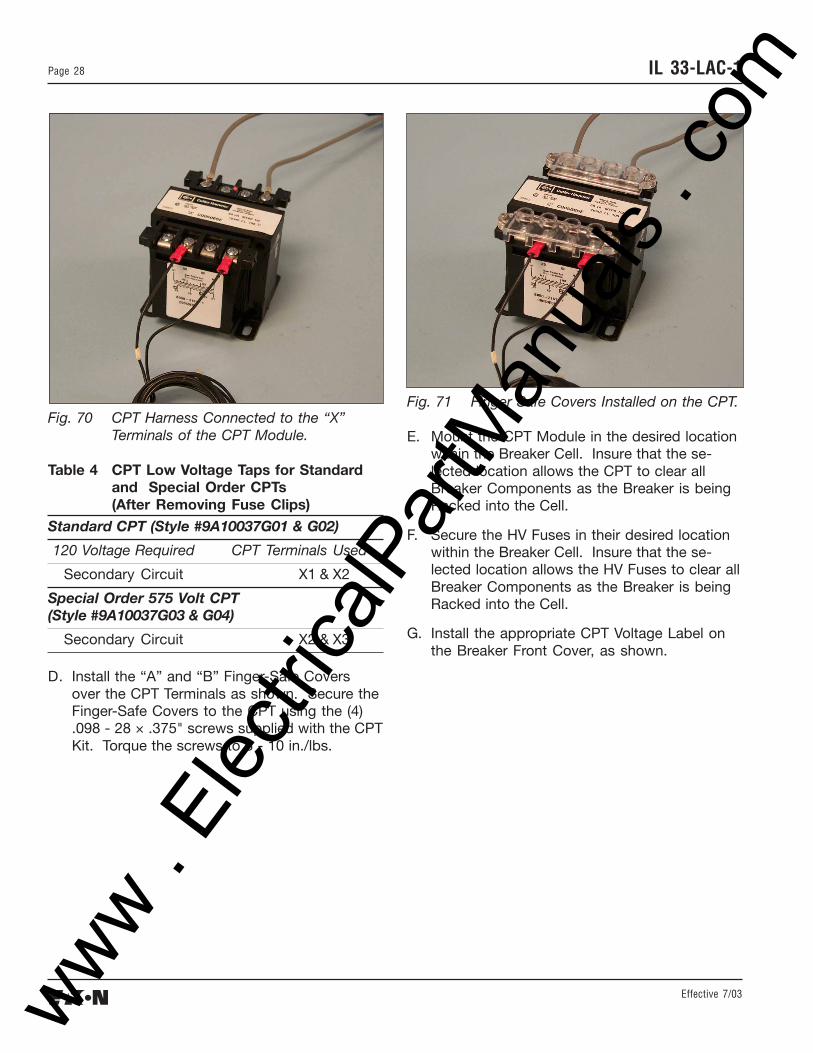
Fig. 70 CPT Harness Connected to the “X”Terminals of the CPT Module.
Table 4 CPT Low Voltage Taps for Standardand Special Order CPTs(After Removing Fuse Clips)
Standard CPT (Style #9A10037G01 & G02)
120 Voltage Required CPT Terminals Used
Secondary Circuit X1 & X2
Special Order 575 Volt CPT(Style #9A10037G03 & G04)
Secondary Circuit X2 & X3
D. Install the “A” and “B” Finger-Safe Coversover the CPT Terminals as shown. Secure theFinger-Safe Covers to the CPT using the (4).098 - 28 × .375" screws supplied with the CPTKit. Torque the screws to 8 - 10 in./lbs.
Fig. 71 Finger Safe Covers Installed on the CPT.
E. Mount the CPT Module in the desired locationwithin the Breaker Cell. Insure that the se-lected location allows the CPT to clear allBreaker Components as the Breaker is beingRacked into the Cell.
F. Secure the HV Fuses in their desired locationwithin the Breaker Cell. Insure that the se-lected location allows the HV Fuses to clear allBreaker Components as the Breaker is beingRacked into the Cell.
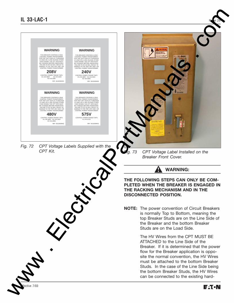
G. Install the appropriate CPT Voltage Label onthe Breaker Front Cover, as shown.
www . El
ectric
alPar
tMan
uals
. com
Effective 7/03
Page 29IL 33-LAC-1
208VCONTROL POWER TRANSF. TAPS
H1–H4=480V H2–H4=240VH3–H4=208V
WARNINGTHIS BREAKER CONTAINS A 50VA
CONTROL POWER TRANSFORMER FOR TRIP UNIT DISPLAY. IF BREAKERIS USED ON A LINE VOLTAGE OTHERTHAN SHOWN. THE CPT TAPS MUST BE CHANGED BEFORE ENERGIZING.FAILURE TO DO SO WILL RESULT IN
DAMAGE TO THE TRIP UNIT AND / ORCONTROL POWER TRANSFORMER
NP# 9A10039H04
240VCONTROL POWER TRANSF. TAPS
H1–H4=480V H2–H4=240VH3–H4=208V
WARNINGTHIS BREAKER CONTAINS A 50VA
CONTROL POWER TRANSFORMER FOR TRIP UNIT DISPLAY. IF BREAKERIS USED ON A LINE VOLTAGE OTHERTHAN SHOWN. THE CPT TAPS MUST BE CHANGED BEFORE ENERGIZING.FAILURE TO DO SO WILL RESULT IN
DAMAGE TO THE TRIP UNIT AND / ORCONTROL POWER TRANSFORMER
NP# 9A10039H03
480VCONTROL POWER TRANSF. TAPS
H1–H4=480V H2–H4=240VH3–H4=208V
WARNINGTHIS BREAKER CONTAINS A 50VA
CONTROL POWER TRANSFORMER FOR TRIP UNIT DISPLAY. IF BREAKERIS USED ON A LINE VOLTAGE OTHERTHAN SHOWN. THE CPT TAPS MUST BE CHANGED BEFORE ENERGIZING.FAILURE TO DO SO WILL RESULT IN
DAMAGE TO THE TRIP UNIT AND / ORCONTROL POWER TRANSFORMER
NP# 9A10039H02
575VCONTROL POWER TRANSF. TAPS
H1–H4=575V
WARNINGTHIS BREAKER CONTAINS A 50VA
CONTROL POWER TRANSFORMER FOR TRIP UNIT DISPLAY. IF BREAKERIS USED ON A LINE VOLTAGE OTHERTHAN SHOWN. THE CPT TAPS MUST BE CHANGED BEFORE ENERGIZING.FAILURE TO DO SO WILL RESULT IN
DAMAGE TO THE TRIP UNIT AND / ORCONTROL POWER TRANSFORMER
NP# 9A10039H01
Fig. 72 CPT Voltage Labels Supplied with theCPT Kit. Fig. 73 CPT Voltage Label Installed on the
Breaker Front Cover.
WARNING:
THE FOLLOWING STEPS CAN ONLY BE COM-PLETED WHEN THE BREAKER IS ENGAGED INTHE RACKING MECHANISM AND IN THEDISCONNECTED POSITION.
NOTE: The power convention of Circuit Breakersis normally Top to Bottom, meaning thetop Breaker Studs are on the Line Side ofthe Breaker and the bottom BreakerStuds are on the Load Side.
The HV Wires from the CPT MUST BEATTACHED to the Line Side of theBreaker. If it is determined that the powerflow for the Breaker application is oppo-site the normal convention, the HV Wiresmust be attached to the bottom BreakerStuds. In the case of the Line Side beingthe bottom Breaker Studs, the HV Wirescan be connected to the existing hard-
www . El
ectric
alPar
tMan
uals
. com
Effective 7/03
IL 33-LAC-1Page 30
ware on the bottom Studs. This will besimilar to the procedure detailed earlierfor connection of the PT Wires.
NOTE: The Line Side HV Wires may be longerthan necessary. Before cutting the wires,be sure that sufficient length is left so thatthe HV Wire Fuses are accessible andthat the connections can be made to thehardware on the Fuse Cradle.
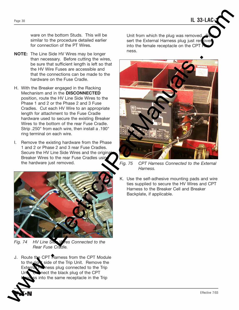
H. With the Breaker engaged in the RackingMechanism and in the DISCONNECTEDposition, route the HV Line Side Wires to thePhase 1 and 2 or the Phase 2 and 3 FuseCradles. Cut each HV Wire to an appropriatelength for attachment to the Fuse Cradlehardware used to secure the existing BreakerWires to the bottom of the rear Fuse Cradle.Strip .250" from each wire, then install a .190"ring terminal on each wire.
I. Remove the existing hardware from the Phase1 and 2 or Phase 2 and 3 rear Fuse Cradles.Secure the HV Line Side Wires and the originalBreaker Wires to the rear Fuse Cradles usingthe hardware just removed.
Unit from which the plug was removed. Rein-sert the External Harness plug just removedinto the female receptacle on the CPT Har-ness.
Fig. 74 HV Line Side Wires Connected to theRear Fuse Cradle.
J. Route the CPT Harness from the CPT Moduleto the right side of the Trip Unit. Remove theExternal Harness plug connected to the TripUnit. Connect the black plug of the CPTHarness into the same receptacle in the Trip
Fig. 75 CPT Harness Connected to the ExternalHarness.
K. Use the self-adhesive mounting pads and wireties supplied to secure the HV Wires and CPTHarness to the Breaker Cell and BreakerBackplate, if applicable.
www . El
ectric
alPar
tMan
uals
. com
Effective 7/03
Page 31IL 33-LAC-1
STEP 9: FINAL BREAKER PREPARATION
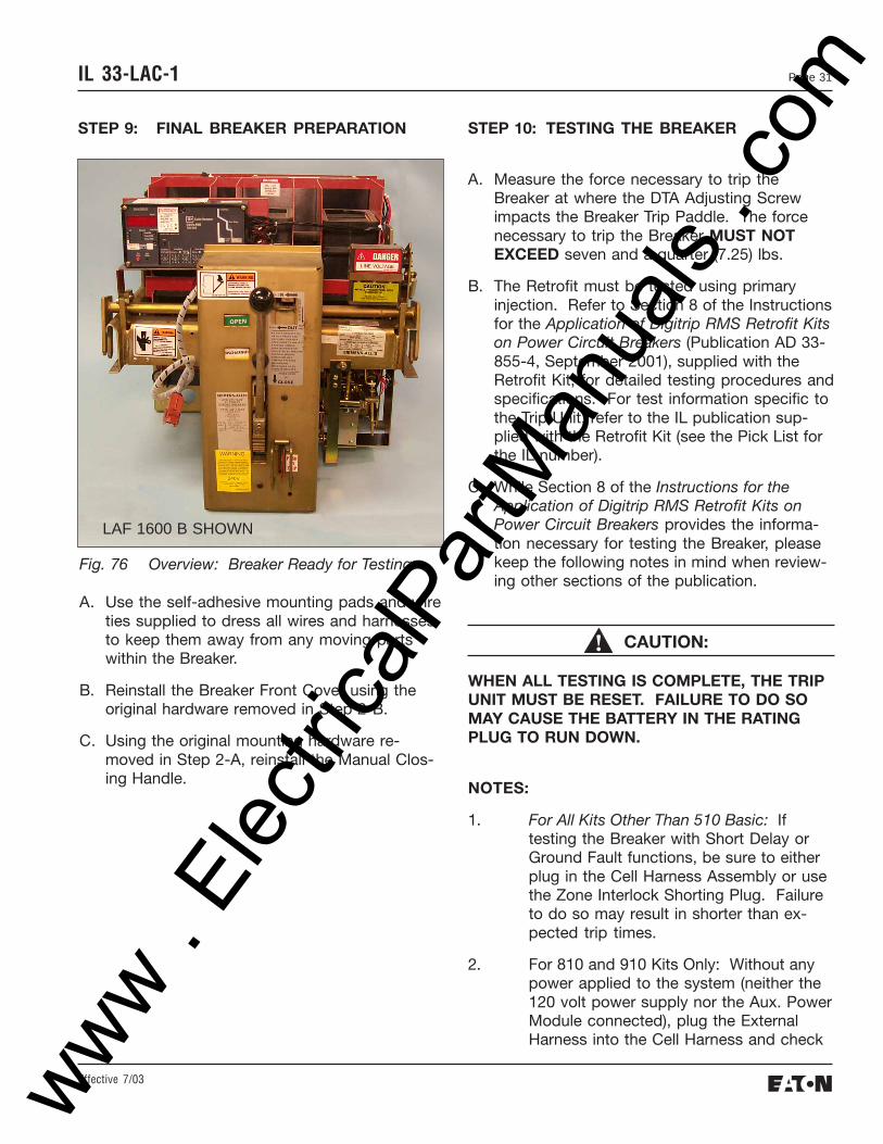
Fig. 76 Overview: Breaker Ready for Testing.
A. Use the self-adhesive mounting pads and wireties supplied to dress all wires and harnessesto keep them away from any moving partswithin the Breaker.
B. Reinstall the Breaker Front Cover using theoriginal hardware removed in Step 2-B.
C. Using the original mounting hardware re-moved in Step 2-A, reinstall the Manual Clos-ing Handle.
LAF 1600 B SHOWN
STEP 10: TESTING THE BREAKER
A. Measure the force necessary to trip theBreaker at where the DTA Adjusting Screwimpacts the Breaker Trip Paddle. The forcenecessary to trip the Breaker MUST NOTEXCEED seven and a quarter (7.25) lbs.
B. The Retrofit must be tested using primaryinjection. Refer to Section 8 of the Instructionsfor the Application of Digitrip RMS Retrofit Kitson Power Circuit Breakers (Publication AD 33-855-4, September 2001), supplied with theRetrofit Kit, for detailed testing procedures andspecifications. For test information specific tothe Trip Unit, refer to the IL publication sup-plied with the Retrofit Kit (see the Pick List forthe IL number).
C. While Section 8 of the Instructions for theApplication of Digitrip RMS Retrofit Kits onPower Circuit Breakers provides the informa-tion necessary for testing the Breaker, pleasekeep the following notes in mind when review-ing other sections of the publication.
CAUTION:
WHEN ALL TESTING IS COMPLETE, THE TRIPUNIT MUST BE RESET. FAILURE TO DO SOMAY CAUSE THE BATTERY IN THE RATINGPLUG TO RUN DOWN.
NOTES:
1. For All Kits Other Than 510 Basic: Iftesting the Breaker with Short Delay orGround Fault functions, be sure to eitherplug in the Cell Harness Assembly or usethe Zone Interlock Shorting Plug. Failureto do so may result in shorter than ex-pected trip times.
2. For 810 and 910 Kits Only: Without anypower applied to the system (neither the120 volt power supply nor the Aux. PowerModule connected), plug the ExternalHarness into the Cell Harness and check
www . El
ectric
alPar
tMan
uals
. com
Effective 7/03
IL 33-LAC-1Page 32
the impedance between COM 1 and COM2. The impedance should be betweenone (1) and three (3) ohms. If the imped-ance is not within this range, trace thewiring and examine each connection toassure its integrity.
Confirm that the PowerNet communica-tion wiring is correct by following theprocedures detailed in Section 7.4 of theInstructions for the Application of DigitripRMS Retrofit Kits on Power Circuit Break-ers. Note that for 810 and 910 Kits, theimpedance between COM 1 and COM 2should be between one (1) and three (3)ohms.
When testing is complete, disconnect theExternal Harness from the Cell Harness.Final External Harness connection will beperformed later in the Retrofit Process.
STEP 11: MOUNTING THE CELL HARNESS
A. The Cell Harness is to be mounted in theBreaker Cell. The connector end is to bemounted on the right side of the Cell, in alocation suitable for connection with theExternal Harness. The Terminal Blocks can bemounted anywhere space is available in theCell as long as connection to the ExternalHarness can be made.
B. Route the Cell Harness wiring to keep it awayfrom any moving parts within the Cell Housing.
www . El
ectric
alPar
tMan
uals
. com
Effective 7/03
Page 33IL 33-LAC-1
STEP 12: INSTALLING THE RETROFITTEDBREAKER IN THE CELL
WARNING:
DO NOT LEAVE THE BREAKER IN AN INTERME-DIATE POSITION IN THE SWITCHGEAR CELL.ALWAYS LEAVE IT IN THE CONNECTED, DIS-CONNECTED, OR (OPTIONAL) TEST POSITION.FAILURE TO DO SO COULD LEAD TO IM-PROPER POSITIONING OF THE BREAKER ANDFLASHOVER, CAUSING DEATH, SERIOUSPERSONAL INJURY, AND / OR PROPERTYDAMAGE.
NOTE: It is the responsibility of the Retrofitterto insure proper Breaker / Cell fit.When racking the Breaker into theConnected position, the RetrofitterMUST FOLLOW BOTH themanufacturer’s instructions and thecustomer’s safety standards andprocedures for racking a Breaker intothe Connected position.
A. With the Breaker in the Open position and thesprings discharged, slowly rack the Breakerinto the Connected position, making surethere is no interference or binding. TheBreaker should rack smoothly and withoutmechanical interference between any Breakerand Cell parts. The Retrofitter will feel someresistance when the primary fingers connectonto the stabs of the Cell. This is normal.
However, if any unusual resistance is detectedthat could be abnormal interference betweenthe Breaker and Cell parts, stop immediatelyand move the Breaker out of the Connectedposition. Examine what is causing the interfer-ence and correct the situation.
www . El
ectric
alPar
tMan
uals
. com
Effective 7/03
IL 33-LAC-1Page 34
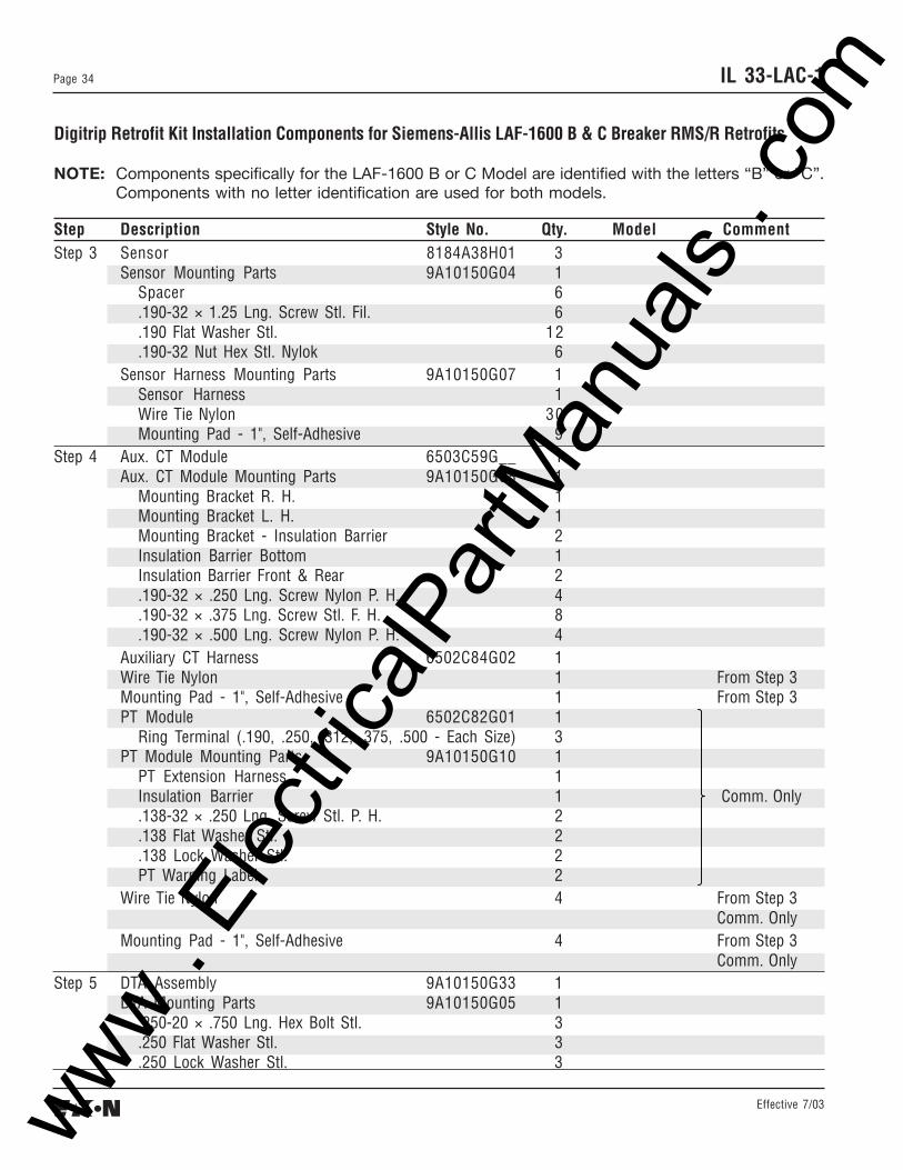
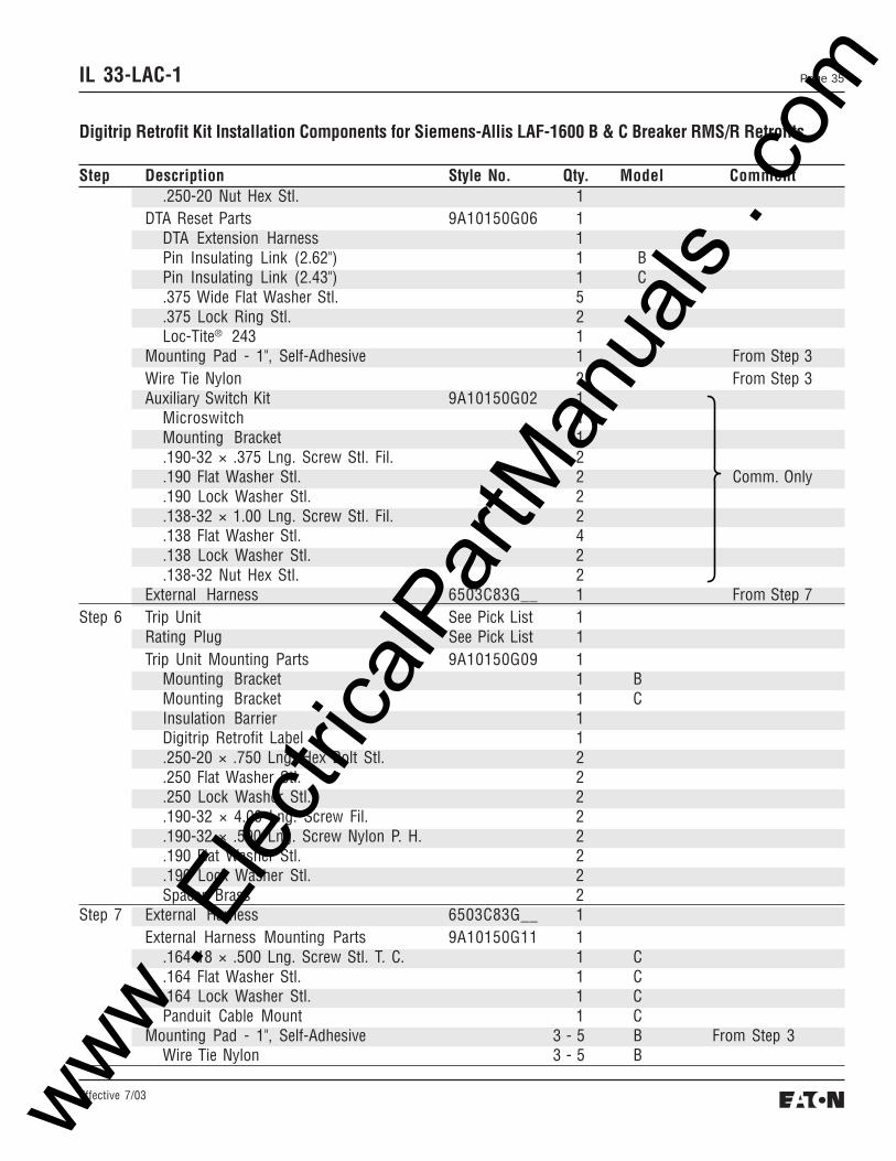
Digitrip Retrofit Kit Installation Components for Siemens-Allis LAF-1600 B & C Breaker RMS/R Retrofits
NOTE: Components specifically for the LAF-1600 B or C Model are identified with the letters “B” or “C”.Components with no letter identification are used for both models.
Mounting Bracket R. H. 1Mounting Bracket L. H. 1Mounting Bracket - Insulation Barrier 2Insulation Barrier Bottom 1Insulation Barrier Front & Rear 2.190-32 × .250 Lng. Screw Nylon P. H. 4.190-32 × .375 Lng. Screw Stl. F. H. 8.190-32 × .500 Lng. Screw Nylon P. H. 4
Auxiliary CT Harness 6502C84G02 1Wire Tie Nylon 1 From Step 3Mounting Pad - 1", Self-Adhesive 1 From Step 3PT Module 6502C82G01 1
Ring Terminal (.190, .250, .312, .375, .500 - Each Size) 3PT Module Mounting Parts 9A10150G10 1
Mounting Pad - 1", Self-Adhesive 2 From Step 3 CPT Only
Wire Tie Nylon 2 From Step 3 CPT Only
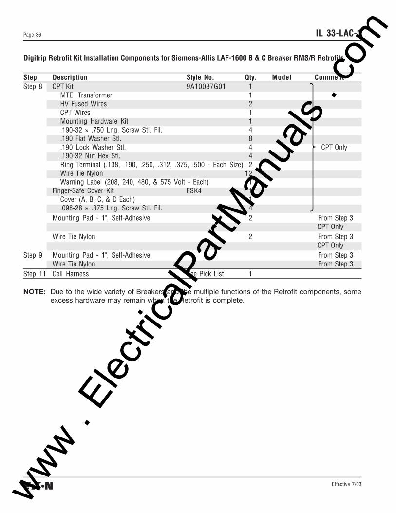
Step 9 Mounting Pad - 1", Self-Adhesive From Step 3Wire Tie Nylon From Step 3
Step 11 Cell Harness See Pick List 1
NOTE: Due to the wide variety of Breakers and the multiple functions of the Retrofit components, someexcess hardware may remain when the Retrofit is complete.
www . El
ectric
alPar
tMan
uals
. com
Effective 7/03
Page 37IL 33-LAC-1
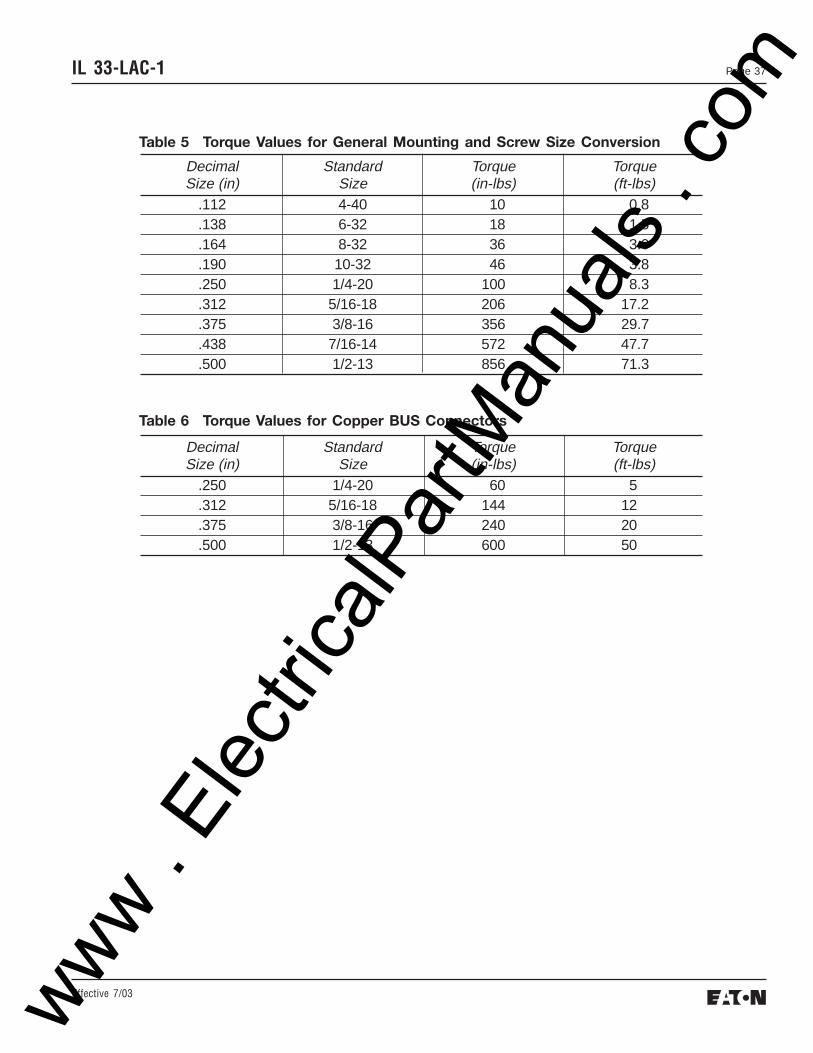
Decimal Standard Torque TorqueSize (in) Size (in-lbs) (ft-lbs)
.112 4-40 10 0.8
.138 6-32 18 1.5
.164 8-32 36 3.0
.190 10-32 46 3.8
.250 1/4-20 100 8.3
.312 5/16-18 206 17.2
.375 3/8-16 356 29.7
.438 7/16-14 572 47.7
.500 1/2-13 856 71.3
Decimal Standard Torque TorqueSize (in) Size (in-lbs) (ft-lbs)
.250 1/4-20 60 5
.312 5/16-18 144 12
.375 3/8-16 240 20
.500 1/2-13 600 50
Table 5 Torque Values for General Mounting and Screw Size Conversion
Table 6 Torque Values for Copper BUS Connectors
www . El
ectric
alPar
tMan
uals
. com
Effective 7/03
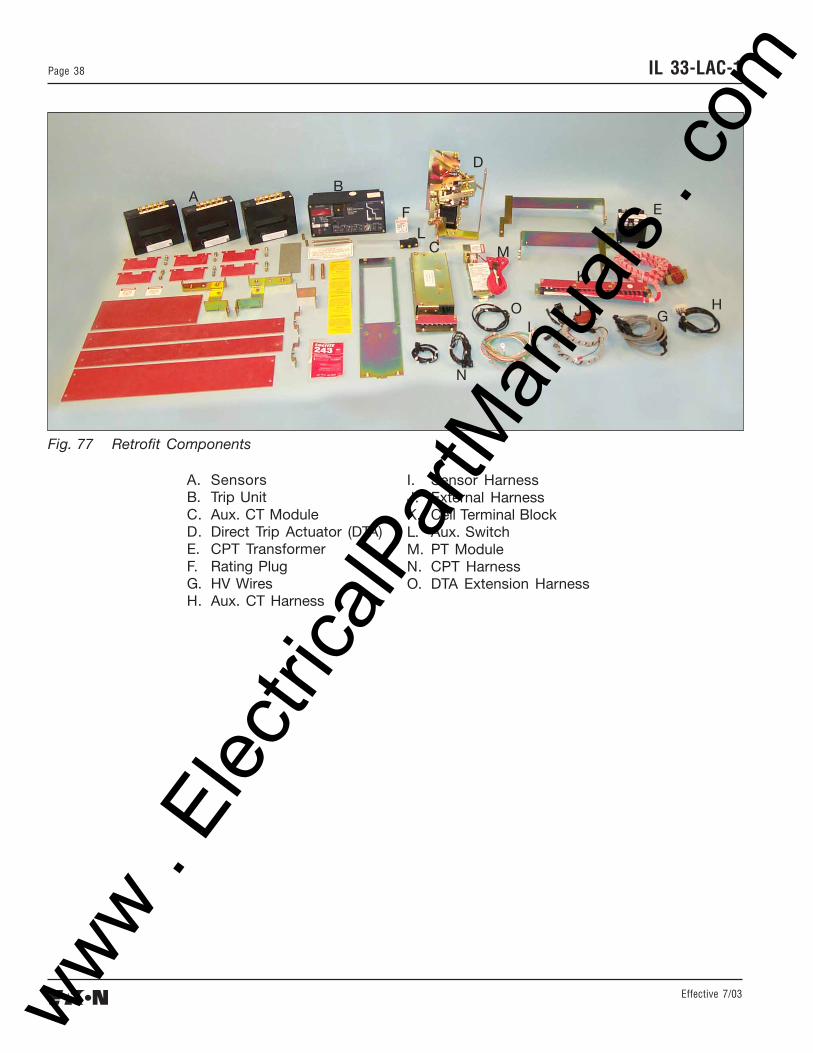
IL 33-LAC-1Page 38
A. SensorsB. Trip UnitC. Aux. CT ModuleD. Direct Trip Actuator (DTA)E. CPT TransformerF. Rating PlugG. HV WiresH. Aux. CT Harness
We wish to thank you for purchasing the Digitrip Retrofit System. Digitrip Retrofit Kits are designed and manufactured inAmerica with pride. All the components are engineered to fit the existing Circuit Breaker with little or no modifications to theexisting Breaker. However due to the wide variety and vintage of Breakers in use today, an occasional problem may arise.Please contact us with any questions, comments or concerns.
Phone: 1-800-937-5487 Fax. (724) 779-5899
The instructions for installation, testing, maintenance, or repair herein are provided for the use of theproduct in general commercial applications and may not be appropriate for use in nuclear applications. Additionalinstructions may be available upon specific request to replace, amend, or supplement these instructions to qualifythem for use with the product in safety-related applications in a nuclear facility.
The information, recommendations, descriptions, and safety notations in this document are based onCutler-Hammer’s experience and judgement with respect to Retrofitting of Power Breakers. This information shouldnot be considered to be all inclusive or covering all contingencies. If further information is required, Cutler-Hammershould be consulted.
NO WARRANTIES, EXPRESSED OR IMPLIED, INCLUDING WARRANTIES OF FITNESS FOR A PARTICULARPURPOSE OR MERCHANTABILITY, OR WARRANTIES ARISING FROM COURSE OF DEALING OR USAGEOF TRADE, ARE MADE REGARDING THE INFORMATION, RECOMMENDATIONS AND DESCRIPTIONSCONTAINED HEREIN. In no event will Cutler-Hammer be responsible to the user in contract, in tort (includingnegligence), strict liability or otherwise, for any special, indirect, incidental, or consequential damage or losswhatsoever, including but not limited to damage to or loss of use of equipment, plant or power system, cost of capital,loss of profits or revenues, cost of replacement power, additional expenses in the use of existing power facilities, orclaims against the user by its customers resulting from the use of the information, recommendations, anddescriptions contained herein.


![Digitrip RMS 310 Electronic Circuit Breakers with Interchangeable … · 2015-07-16 · R-Frame January 2001 Vol. 1, Ref. No. [0568] Digitrip RMS 310 Electronic Circuit Breakers with](https://static.documents.pub/doc/80x56/5b3eea737f8b9a91078b7836/digitrip-rms-310-electronic-circuit-breakers-with-interchangeable-2015-07-16.jpg)


