Integrated Electro-Aeromechanical Structures for Low-Cost, Self-DeployingEnvironment Sensors and Disposable UAVs
Paul E. I. Pounds∗ and Surya P. N. Singh
Abstract— This paper presents a novel approach for con-structing light-weight, low-cost air-deployable sensor modulesand miniature unmanned aerial vehicles which consist ofprinted circuit boards as integrated electronic, structural andaerodynamic lift-producing devices. In this way, each aircraftcan be a single-piece, single-manufacturing step assembly,reducing materials, processing and labour costs. This approachallows the fabrication of devices that are sufficiently inexpensiveso as to be economic for single-use or disposable applica-tions, such as long-range sensor deployment for environmentalmonitoring. We present two example low-cost, proof-of-conceptaircraft employing electro-aeromechanical structures — rotary-wing and fixed-wing — and demonstrate their flight perfor-mance.
I. INTRODUCTION
Numerous applications exist where small UAVs may beneeded in large numbers or must be expended in carryingout a mission — for example, where the distance to beflown exhausts the onboard power supply (e.g. long-termsurveying at sea) or where the mission requires destructionof the aircraft (e.g. a guided missile, or carrying sensors intoa volcano). In the past decade autonomous aircraft systemshave become increasingly affordable, but the high unit cost ofminiature Unmanned Aerial Vehicles (UAVs) precludes theuse of UAVs for one-way flights, outside of certain militaryapplications.
Consequently, we seek to reduce the cost of UAVs tothe point where producing and discarding large numbers ofthem may be feasible. UAV system cost has historically beendominated by the specialised sensors and avionics requiredfor flight stability, navigation and autonomy. With the adventof Micro Electro-Mechanical System (MEMS), avionics maynot be the primary cost driver for low-end applications.Today, sensors suitable for stabilisation of a mini-UAV can behad for under $20. In large volumes, materials processing,fabrication and labour become the principal cost. Thus, torealise disposable UAVs, these drivers must be simplified,reduced and, where possible, eliminated through tight in-tegration of multiple functions into fewer systems: fewercomponents, fewer manufacturing steps, less material.
Recent advances in mili- (order of 1 mm) and meso-scale (order of 10 mm) aircraft highlight the potential ofsuch integrated aeromechanical structures. For example, Har-vard’s robot fly employs micro-machined folded substratesthat assemble from laminar sheets [1]. Similarly, Berkeley’sfolded meso-scale running robots are fabricated used the
Paul Pounds and Surya Singh are lecturers at the University of Queens-land Robotics Design Lab, St. Lucia, QLD, Australia [email protected], [email protected]*Corresponding author.
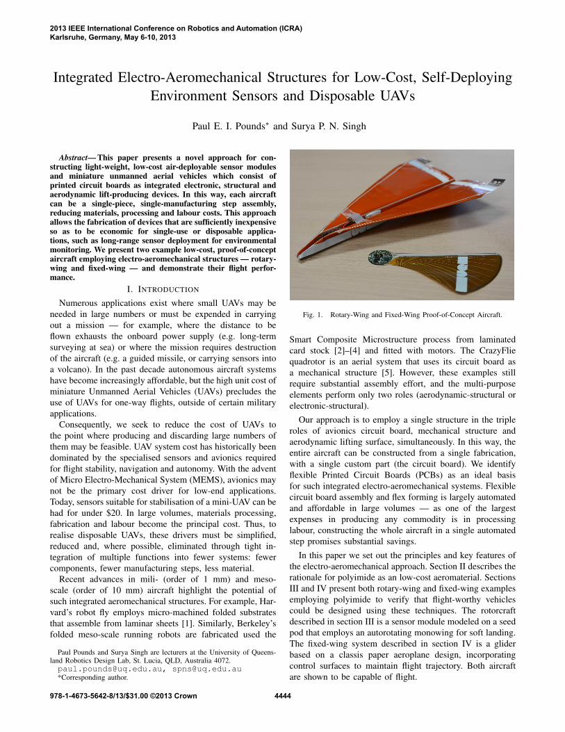
Fig. 1. Rotary-Wing and Fixed-Wing Proof-of-Concept Aircraft.
Smart Composite Microstructure process from laminatedcard stock [2]–[4] and fitted with motors. The CrazyFliequadrotor is an aerial system that uses its circuit board asa mechanical structure [5]. However, these examples stillrequire substantial assembly effort, and the multi-purposeelements perform only two roles (aerodynamic-structural orelectronic-structural).
Our approach is to employ a single structure in the tripleroles of avionics circuit board, mechanical structure andaerodynamic lifting surface, simultaneously. In this way, theentire aircraft can be constructed from a single fabrication,with a single custom part (the circuit board). We identifyflexible Printed Circuit Boards (PCBs) as an ideal basisfor such integrated electro-aeromechanical systems. Flexiblecircuit board assembly and flex forming is largely automatedand affordable in large volumes — as one of the largestexpenses in producing any commodity is in processinglabour, constructing the whole aircraft in a single automatedstep promises substantial savings.
In this paper we set out the principles and key features ofthe electro-aeromechanical approach. Section II describes therationale for polyimide as an low-cost aeromaterial. SectionsIII and IV present both rotary-wing and fixed-wing examplesemploying polyimide to verify that flight-worthy vehiclescould be designed using these techniques. The rotorcraftdescribed in section III is a sensor module modeled on a seedpod that employs an autorotating monowing for soft landing.The fixed-wing system described in section IV is a gliderbased on a classis paper aeroplane design, incorporatingcontrol surfaces to maintain flight trajectory. Both aircraftare shown to be capable of flight.
2013 IEEE International Conference on Robotics and Automation (ICRA)Karlsruhe, Germany, May 6-10, 2013
Fig. 2. Electro-Aeromechanical System Hybridisation.
II. DESIGN PRINCIPLES
The electro-aeromechanical approach is to combine thethree most complex system components — the avionicsboard, fuselage and aerodynamic surfaces — into a singlemulti-purpose part. Much like how mechatronics is a hy-brid of electrical and mechanical systems and avionics isa hybrid of aerodynamic and electronic systems, electro-aeromechanical systems hybridise all three domains (seeFig. 2). Flexible and rigid circuit board material (and hybrids)are used to form lifting surfaces which are sufficiently strongto carry the structural loads of the aircraft. This is distinctfrom other efforts that employ PCBs as purely mechanicalstructures; the circuit board is both mechanical and aero-dynamic. In general, circuit design constraints are moredemanding than that of simpler aerodynamic or structuralfeatures — it is less efficient to adapt a conventionally-assembled wing to become a circuit than it is to adapt acircuit to become a wing.
A. The Case for Polyimide
As electro-aeromechanical systems are specifically in-tended for flight, they must satisfy the performance require-ments common to aerostructures, in addition to being suitablefor electrical circuits. The drivers for high integration andlow labour cost further limits choices to those materialsthat are already employed in established mass-manufactureprocesses. We have identified flexible polyimide PCBs as anideal material for constructing these devices.
Flexible PCBs consist of light-weight polyimide substratewith layered copper plating. These semi-stiff assemblies areoptimised for their electrical characteristics. They can beautomatically loaded with modern surface mount or through-hole components and safely raised to soldering temperature.Rigid FR4 PCBs and back-panel rigidisers can be bonded topolyimide to form stiffer sections, at the expense of weight1.
The small size of mini-UAVs and air-deployable sensormodules (order of 10 mm) allows low strength materials to beused, which are not normally considered for aeromechanicalstructures [6]. The required strength of an airframe is de-pendent upon the aerodynamic loading of the wings, which
1EAM is equally applicable to non-flex rigid PCBs, but their higherdensities and limited planar construction make flex boards more attractive.
Polyimide
Better
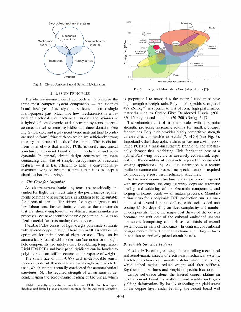
Fig. 3. Strength of Materials vs Cost (adapted from [7]).
is proportional to mass; thus the material used must havehigh strength to weight ratio. Polyimide’s specific strength of477 kNmkg−1 is superior to that of some high performancematerials such as Carbon-Fibre Reinforced Plastic (200–350 kNmkg−1) and titanium (20–200 kNmkg−1) [7].
The volumetric cost of materials scales with its specificstrength, providing increasing returns for smaller, cheaperfabrications. Polyimide provides highly competitive strengthvs unit cost, comparable to metals [7, p120] (see Fig. 3).Importantly, the lithographic etching processing cost of poly-imide PCBs is a mass-manufacture technique, and substan-tially cheaper than machining. Unit fabrication cost of ahybrid PCB-wing structure is extremely economical, espe-cially in the quantities of thousands required for distributedsensing applications [8]. As PCB fabrication is a readilyavailable commercial process, no special setup is requiredfor producing electro-aeromechanical structures.
As the aerodynamic structure is a single piece integratedwith the electronics, the only assembly steps are automaticloading and soldering of the electronic components, andforging of flexure bends — all mature processes. Manufac-turing setup for a polyimide PCB production run is a one-off cost of several hundred dollars, with each loaded unitcosting $5–50, depending on size, complexity and numberof components. Thus, the major cost driver of the devicesbecomes the unit cost of the onboard embedded sensorsthemselves (comprising as much as two-thirds of overallsystem cost, in units of thousands). In contrast, conventionaldesigns require fabrication of an airframe and lifting surfacesin addition to similarly priced circuit boards.
B. Flexible Structure Features
Flexible PCBs offer great scope for controlling mechanicaland aerodynamic aspects of electro-aeromechanical systems.Unetched sections can maintain deformation and bends,while etched regions reduce weight and alter stiffness.Rigidisers add stiffness and weight in specific locations.
Unlike polyimide alone, the layered copper plating onflexible circuit boards is malleable and readily undergoesyielding deformation. By locally exceeding the yield stressof the copper layer under bending, the circuit board will
be permanently deformed (see Fig. 4a). Application of theseloads while hot prevents stress fracture formation and fatigueof the boards. This process is commonly carried out inproducing wiring harnesses for complex consumer productssuch as cameras [8, p4]. Hot forging operations produceprecision 3D shape with bending radii as low as five timesthe copper-polyimide sandwich thickness (typically 150–600 µm). These bends do not damage the substrate [8, p5],allowing complex aerodynamic shapes to conduct signals andpower to actuators and sensors.
Prior to etching, copper-plated sections of the circuit boardhave higher stiffness (and thus less deformation under load),but also more weight. Removal of copper is thus a tradeoffbetween rigidity, aerodynamic loading, overall weight of theaircraft, and the electrical current that must be carried bythat section of board.
By retaining parallel strips of material in a particulardirection (called ‘stringers’), the polyimide can be made stiffin one direction (transverse to bending load), but flexiblein another, while decreasing overall weight (see Fig. 4b).Modulating the amount of copper plating removed over asurface allows tuned anisotropic compliance in complex pat-terns to be implemented. Selective application of cuts allowsfor flexure seams or bending perforations and mounting ofactuator hardware.
By selectively removing sections of copper, or by addingrigidisers, a seam or flexure may be constructed. This maybe used to allow easier deformation during manufacture (seeFig. 4c) or to create flexible attached subsections such ascontrol surfaces.
Forged 3D shapes can be exploited to create especiallystrong directional structures2. A set of three successive bendsof alternating direction produce a corrugated spine (seeFig. 4d) that resists bending perpendicular to the axis of thespine (as commonly seen in corrugated iron siding). Theseout-of-plane shapes can themselves be repurposed as aerody-namic stabilisers and conductors of control surface signals.In this way, even a single surface element may performelectronic, structural and aerodynamics task simultaneously.
C. Aerodynamic IntegrationA variety of features can be combined into PCBs in
addition to their role as electronic devices. Beyond mechan-
2A limitation of electro-aeromechanical construction is that that the lowbending strength of simple flat-plate construction prevents scaling beyond100s of millimeters. Application of 3D construction techniques, thoughmore labour-intensive, permits this approach to be extended to much largerdevices.
ical or structural systems, it is now commonplace for someclasses of plated connector (e.g. USB tabs), passive resistive,capacitive and inductive traces and RF elements and antennasto be implemented directly on a PCB. Tighter integration ofthis kind results in increasing returns, as decreasing weightand complexity allow for smaller, more optimised designswith less overhead.
The addition of aerodynamic functions to PCBs exploitsthe flat plate structure of the boards. Reynolds Numbers(RE) encountered by UAVs at the meso-scale are very low.Ideal low-RE airfoils are typically sharp, with a low ratio ofthickness to chord length, that slice through more viscous airefficiently [9]. In this domain, the flat structure of polyimidesheet or FR4 fibreglass board is servicable as an airfoil.In fact, at very low Reynolds Numbers flat plate airfoilscan be more efficient than more complex airfoils [10]. Byintroducing right-angle bends aligned with the direction oftravel, vertical stabilisers and winglets are formed from asingle contiguous sheet of material.
Beyond flat plate airfoils, malleable flex circuits allowwing cross-sections to be formed with camber by forgingoperations (see section II-B) for improved aerodynamicefficiency at larger scales. For both flexible and rigid boards,the outline of the circuit can be precisely controlled, allowingfor balanced weight and aerodynamic loading essential fortrimmed flight.
In general, the largest aerodynamic stress of a wingstructure occurs near the root, with less loading towardsthe extremities [9], [11]. For this reason, membrane wingconstruction is used — copper is removed in bulk far fromthe wing root, but retained around stress points. A networkof stringers in the form of wing vasculature provides trans-verse stiffness. A large number of miniature aerodynamicstructures found in nature are flat membrane wings [12]. Bycarefully designing stringers and flexure modes, aeroelasticmechanical effects can be leveraged such as in mini- andmeso-scale ornithopters [1].
These principles are demonstrated in two example aircraft— both rotary-wing and fixed-wing. We show that they arecapable of passive flight and report their performance3.
3This paper is principally concerned with process and application of thehighly-integrated electro-aeromechanical construction approach, and doesnot consider the detailed analytical aerodynamic or control design of theexample aircraft.
4446
III. ROTARY-WING CONCEPT
The first proof-of-concept electro-aeromechanical designis a self-deploying sensor module. Distributed sensing offersa variety of benefits for environmental monitoring appli-cations such as bushfire fighting. The cost and delay inmanually distributing sensors over a large geographic areamakes aerial deployment via air-drop a compelling tech-nology. However, the need to ruggardise sensors to survivefree-fall impact, or the cost of including aerodynamic arrestdevices such as parachutes for soft-landing, makes aerialdeployment less viable.
A natural example of aerial distribution under cost con-straints is the maple, or ‘samara’, seed. These well-knownseeds consist of a fibrous fruit that is elongated into a wing[13]. When the seed falls from the tree, the wing autorotatesunder passive aerodynamic forces that slow the descent.This increases the seed’s chances of being caught by a gustand distributed far from the parent, conferring a competitiveadvantage. The relative growth ‘cost’ of the wing is low, dueto its integration in the existing structures of the seed.
The concept of using a rotating monowing as a roboticsplatform is not new. Extensive work was undertaken atUniversity at Maryland by Ulrich et al, who developed aseries of increasingly small UAVs using rotary flight [14],[15]. This work included analysis of the autorotation modeof these vehicles [16], [17]. Similar work on propelledmonowing UAV flight has also been carried out by Lockheed(‘Samarai’) [18] and VeraTech (‘Phantom’) [19]. Ulrich etal have the smallest demonstrator, at 270 mm wingspan. Ineach case, the aircraft is quite large, actively propelled andrelatively complex — these vehicles would not be classed asexpendable.
In contrast, our approach is to use the same rationale as thetree to reduce the cost of an aerial deployment mechanism.We demonstrate that the PCB substrate that forms the sensorcan be repurposed to act as a wing (see Fig. 5), reducing thecomplexity and fabrication cost of the sensor system. Thewing section performs the aerodynamic braking needed toarrest the fall of the sensor when deployed from the air; thiseliminates the need for additional aerodynamic devices suchas parachutes or rotors, and any additional actuators4.
A. Electronics
Onboard sensors include a Freescale MPL115a pressuresensor, Avago APDS-9002 ambient light sensor, and a Sen-siron SHT-25 relative humidity and temperature sensor, allcontrolled by a Microchip PIC 16F690 microprocessor. AnInvensense MPU-6050 MEMS IMU detects descent spiralmotion, as well as orientation on the ground. This allows thesensor to only begin taking measurements and transmittingdata once landed.
Sensor measurements are transmitted to a receiving base-station, or an orbiting UAV mothership by a 434 MHz radio
4While both example systems described in this paper are passive glidersto target the disposable system goal, the electro-aeromechanical approachdoes not preclude propulsion systems.
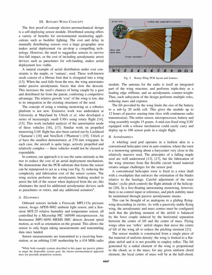
Fig. 5. Rotary-Wing PCB layout and features.
module. The antenna for the radio is itself an integratedpart of the wing structure, and performs triple-duty as aleading edge stiffener, and an aerodynamic counter-weight.Thus, each subsystem of the design performs multiple roles,reducing mass and expense.
The lift provided by the wing limits the size of the batteryto a sub-1g 20 mAh cell. This gives the module up to12 hours of passive sensing time (less with continuous radiotransmission). The entire sensor, microprocessor, battery andwing assembly weighs 15 grams. A mid-size fixed wing UAVequipped with a release mechanism could easily carry anddeploy up to 100 sensor pods in a single flight.
B. Aerodynamics
A whirling seed pod operates in a fashion akin to aconventional helicopter rotor in auto-rotation, where the rotoris a monowing spinning about a barycenter very close to therelatively massive seed. The principles of a falling mapleseed are well understood [13], [17], but the fabrication ofthe wing structure from flat flexible circuit board materialcreates unique challenges for the sensor pod.
A conventional helicopter rotor is fixed to a rotor shaftwith a swashplate that enforces the orientation of the bladesrelative to the fuselage. Careful adjustment of the rotorblades’ cyclic pitch controls the flight attitude of the helicop-ter [20]. In a free-floating autorotating monowing, however,there is no control input or reference, and pitch stability mustbe maintained through passive aerodynamic means.
This can be thought of as analogous to a gliding flying-wing descending in circles. As with a passively-stable flyingwing, the aerodynamic and mass centres must be configuredsuch that the pitching moment of the airfoil is balancedby the force couple induced by the horizontal separationbetween the centre of lift and the centre of mass. Flyingwings often use ‘reflex’ airfoil shapes that move the centreof lift of the wing aft to reduce the pitching moment [21].
The sensor module is constructed from a single piece offlat material of uniform density: the wing is limited to a flat-plate airfoil and it is not possible to employ reflex. The liftgenerated by a radial element of the wing is proportionalto the chord, as is the mass; for any given uniform chordelement, the local centre of mass will be at the half-chord,
4447
while the centre of lift will always be ahead of the quarter-chord. Consequently, there is no chordal or radial planformthat will stabilize a wing of uniform density.
A solution to this problem is to shift the centre of massof the wing forward by adding material to the front of thewing — in this case, a weighted stiffener at the leading edge.By lengthening the chord at the outboard third of the wing,the overall centre of lift can be moved aft, maximising therestorative stability of the configuration.
A descending seed pod autorotates in what is calledthe ‘windmill brake state’ — where the rotation of therotor removes energy from the on-coming vertical wind anddissipates it, slowing the descent of the aircraft. The rate ofdescent in this mode can be shown to be twice the inducedvelocity of the airflow in hover [22, p109]. This indicatesthat the disc-loading of the rotor (the mass of the aircraft,divided by circular planform swept of the rotor) should bekept as low as possible.
As the structure of the sensor pod comprises the rotoritself, increasing the diameter (and thus area) of the rotornecessarily increases the mass of the aircraft. Naively, in-creasing the size of the wing without limit should decreasethe relative contribution of the deadweight of the sensorand power source. However, as the dimensions of a thinwing increases its ability mechanically to support itself underaerodynamic loads degrades and the aerodynamic shape losesintegrity [23]. Consequently, the wing must be sized largeenough such that the disc-loading is sufficient to provide aslow enough descent, but no larger. This is in contrast to thecounter-intuitive case of helicopters, where a heavier aircraftwith a given disc-loading will descend slower than a lighteraircraft of equal disc-loading [22, p139].
As helicopter gross mass decreases, the disc-loading mustalso decrease. The disc-loading of a conventional helicopteris typically greater than 12 kgm−2. An average quadrotorhas a disc-loading of 8 kgm−2. In contrast, the 99 mm longsensor pod wing has a disc-loading of 0.49 kgm−2.
C. Mechanical Structure
The mechanical strength of the wing sets a practical lowerbound on disc-loading; increasing the stiffness of the wingthus increases the overall achievable performance of thedesign. A rigidiser added to the leading edge increases thebending stiffness of the wing and reduces twisting. To furtherimprove the stiffness of the design without contributing sig-nificantly to the mass of the structure, parts of the conductingcopper layer have been left unetched over the surface ofthe wing to form transverse stringers. These mimic thevasculature seen in natural seed pods, and the authors believethey serve the same purpose — rigidising the lightweightflexible aerodynamic structure. The stringers converge at theroot of the wing to provide maximum stiffness at the part ofthe structure under the most load.
Additional copper is left unetched at the wing root tofurther stiffen the wing interface with the sensor circuitry.The aerodynamic loads of the wing can cause small defor-mations leading to delamination and failure of the device.
This leads to premature failure of the device, even under therelatively small cyclic forces of autorotation. By placing acopper levee around the functional circuit traces as strainrelief, the integrity of the electronics is protected.
D. Performance
There are two stable descent modes: spiral descent andplunge. Natural seeds use small ripples in the trailing edgeof the wing to create a aerodynamic imbalance that inducesrotation. As the current design lacks this feature, the devicewill plunge if dropped seed-end down. To avoid this, thesensor is always dropped ‘seed-end up’, so that the devicewill undergo at least one rotation to turn end-over-end; thisrotation is sufficient to initiate the spiral mode.
In plunge, the aerodynamic centre of the seed is alignedvertically above the centre of mass (‘seed-end down’), whichdoes not generate a rotational moment. This offers a muchsmaller cross-section to the vertical on-coming wind, and sodoes little to arrest the descent of the seed (falling 2.5 m inless than 0.75 s).
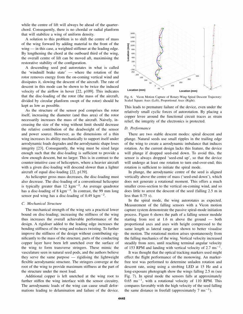
In the spiral mode, the wing autorotates as expected.Measurement of the falling sensors with a Vicon motioncapture system demonstrate the passive spiral-mode initiationprocess. Figure 6 shows the path of a falling sensor modulestarting from rest at 1.6 m above the ground — bothproportional axes and axes with height compressed to thesame length as lateral range are shown to better visualisethe motion. The rotational motion arises spontaneously fromthe falling mechanics of the wing. Vertical velocity increasedsteadily from zero, until reaching terminal angular velocityof 153 RPM and landing with vertical velocity of 2.7 ms−1.
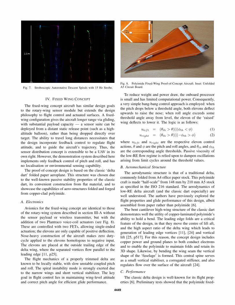
It was thought that the optical tracking markers used mighteffect the flight performance of the monowing. An marker-free test was performed to determine unladen rotation anddescent rate, using using a strobing LED at 15 Hz and along-exposure photograph show the wings falling 2.5 m (seeFig. 7). In spiral mode the sensors falls at approximately0.65 ms−1, with a rotational velocity of 110 RPM. Thiscompares favorably with the high velocity of the seed fallingthe same distance in freefall (approximately 7 ms−1).
4448
Fig. 7. Stroboscopic Autorotative Descent Spirals with 15 Hz Strobe.
IV. FIXED WING CONCEPT
The fixed-wing concept aircraft has similar design goalsto the rotary-wing sensor module but extends the designphilosophy to flight control and actuated surfaces. A fixed-wing configuration gives the aircraft longer range via gliding,with substantial payload capacity — a sensor suite can bedeployed from a distant static release point (such as a high-altitude balloon), rather than being dropped directly overtarget. The ability to travel long distances necessitates thatthe design incorporate feedback control to regulate flightattitude, and to guide the aircraft’s trajectory. Thus, thesensor distribution concept is extensible to be a UAV in itsown right. However, the demonstration system described hereimplements only feedback control of pitch and roll, and hasno localisation or environmental sensing capability.
The proof-of-concept design is based on the classic ‘deltadart’ folded paper aeroplane. This structure was chosen dueto the well-known passive stability properties of the classicdart, its convenient construction from flat material, and toshowcase the capabilities of aero-structures folded and forgedfrom copper-clad polyimide.
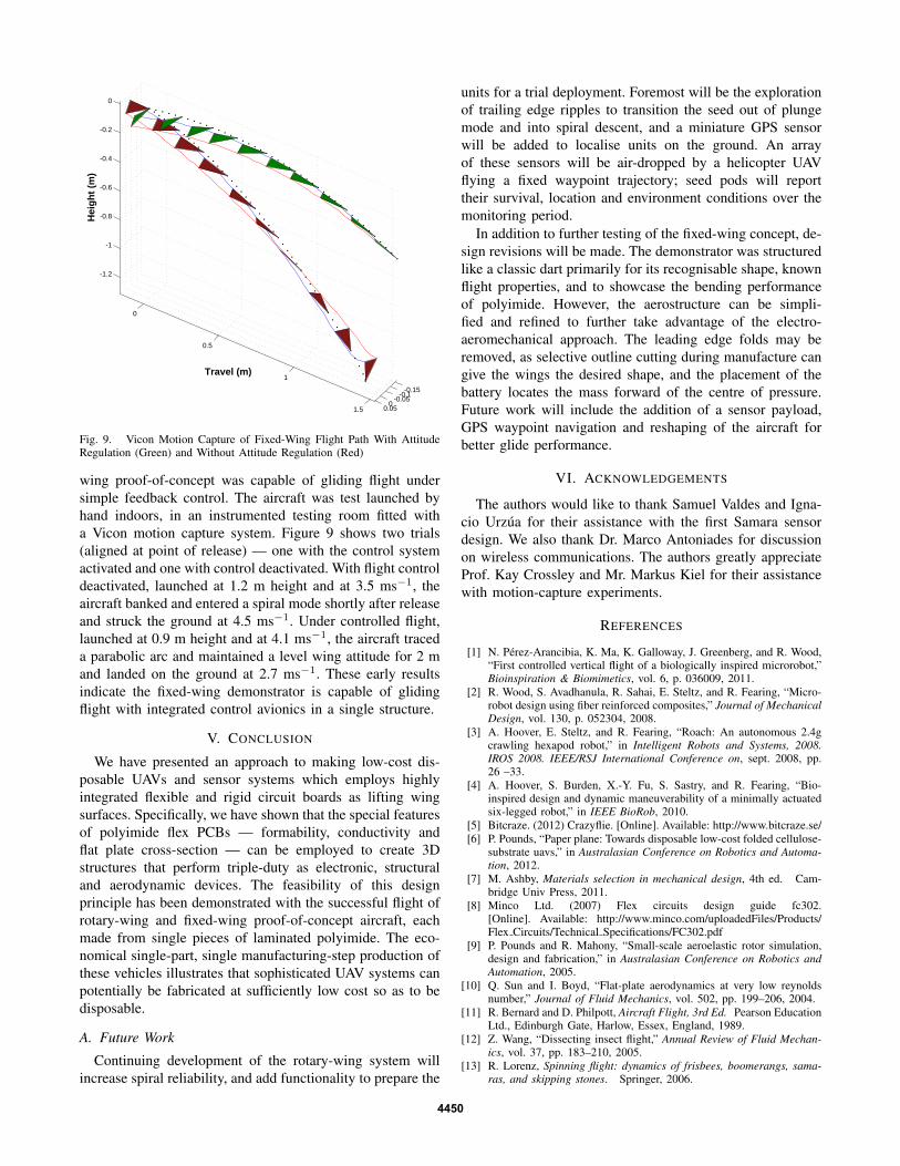
A. Electronics
Avionics for the fixed-wing concept are identical to thoseof the rotary-wing system described in section III-A withoutthe sensor payload or wireless transmitter, but with theaddition of two Plantraco voice-coil actuators (see Fig. 8).These are controlled with two FETs, allowing single-endedactuation; the elevons are only capable of positive deflection.Nose-heavy construction of the aircraft makes zero duty-cycle applied to the elevons homologous to negative input.The elevons are placed at the outside trailing edge of thedelta wing, where the separated vortices flow parallel to theleading edge [11, p25].
The flight mechanics of a properly trimmed delta areknown to be locally stable, with slow unstable coupled pitchand roll. The spiral instability mode is strongly exerted dueto the narrow wings and short vertical stabilizer. The keygoal in flight control lies in maintaining wing-level attitudeand correct pitch angle for efficient glide performance.
To reduce weight and power draw, the onboard processoris small and has limited computational power. Consequently,a very simple bang-bang control approach is employed: whenthe pitch drops below a threshold angle, both elevons deflectupwards to raise the nose; when roll angle exceeds somethreshold angle away from level, the elevon of the ‘raised’wing deflects to lower it. The logic is as follows:
where uleft and uright are the respective elevon controlactions, θ and φ are the pitch and roll angles, and θth and φthare the corresponding angle thresholds. Passive viscosity ofthe low-RE flow regime is relied upon to dampen oscillationsarising from limit cycles around the threshold values.
B. Aeromechanical Structure
The aerodynamic structure is that of a traditional delta,commonly folded from A4 office paper stock. This polyimidecraft is made “half-scale” from 148 mm by 210 mm A5 stockas specified in the ISO 216 standard. The aerodynamics oflow-RE delta aircraft (and the classic dart especially) arewell understood. The authors have previously explored theflight properties and glide performance of this design, albeitassembled from paper rather than polyimide [6].
The bent cantilever high-wing structure of the classic dartdemonstrates well the utility of copper-laminated polyimide’sability to hold a bend. The leading edge folds are a criticalfeature of the design, in that they move the centre of lift aft,and the high aspect ratio of the delta wing which leads togeneration of leading edge vortices [11], [24] and vorticallift [25, p517]. For this reason, the concept design includescopper power and ground planes to both conduct electronsand to enable the polyimide to maintain folds and retain its3D shape. Likewise, by bending the wing seam the verticalshape of the ‘fuselage’ is formed. This central spine servesas a small vertical stabiliser, a corrugated stiffener, and alsoregulates flow over the surface of the aircraft [24].
C. Performance
The classic delta design is well-known for its flight prop-erties [6]. Preliminary tests showed that the polyimide fixed-
4449
-0.15-0.1
-0.050
0.05
0
0.5
1
1.5
-1.2
-1
-0.8
-0.6
-0.4
-0.2
0
Travel (m)
Hei
gh
t (m
)
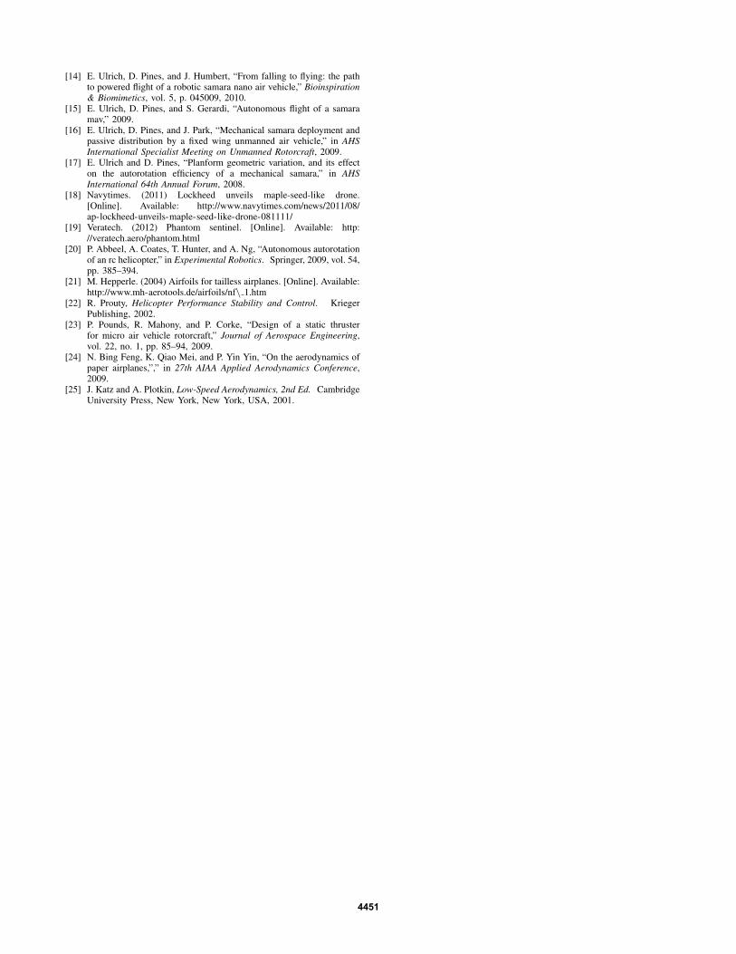
Fig. 9. Vicon Motion Capture of Fixed-Wing Flight Path With AttitudeRegulation (Green) and Without Attitude Regulation (Red)
wing proof-of-concept was capable of gliding flight undersimple feedback control. The aircraft was test launched byhand indoors, in an instrumented testing room fitted witha Vicon motion capture system. Figure 9 shows two trials(aligned at point of release) — one with the control systemactivated and one with control deactivated. With flight controldeactivated, launched at 1.2 m height and at 3.5 ms−1, theaircraft banked and entered a spiral mode shortly after releaseand struck the ground at 4.5 ms−1. Under controlled flight,launched at 0.9 m height and at 4.1 ms−1, the aircraft traceda parabolic arc and maintained a level wing attitude for 2 mand landed on the ground at 2.7 ms−1. These early resultsindicate the fixed-wing demonstrator is capable of glidingflight with integrated control avionics in a single structure.
V. CONCLUSION
We have presented an approach to making low-cost dis-posable UAVs and sensor systems which employs highlyintegrated flexible and rigid circuit boards as lifting wingsurfaces. Specifically, we have shown that the special featuresof polyimide flex PCBs — formability, conductivity andflat plate cross-section — can be employed to create 3Dstructures that perform triple-duty as electronic, structuraland aerodynamic devices. The feasibility of this designprinciple has been demonstrated with the successful flight ofrotary-wing and fixed-wing proof-of-concept aircraft, eachmade from single pieces of laminated polyimide. The eco-nomical single-part, single manufacturing-step production ofthese vehicles illustrates that sophisticated UAV systems canpotentially be fabricated at sufficiently low cost so as to bedisposable.
A. Future Work
Continuing development of the rotary-wing system willincrease spiral reliability, and add functionality to prepare the
units for a trial deployment. Foremost will be the explorationof trailing edge ripples to transition the seed out of plungemode and into spiral descent, and a miniature GPS sensorwill be added to localise units on the ground. An arrayof these sensors will be air-dropped by a helicopter UAVflying a fixed waypoint trajectory; seed pods will reporttheir survival, location and environment conditions over themonitoring period.
In addition to further testing of the fixed-wing concept, de-sign revisions will be made. The demonstrator was structuredlike a classic dart primarily for its recognisable shape, knownflight properties, and to showcase the bending performanceof polyimide. However, the aerostructure can be simpli-fied and refined to further take advantage of the electro-aeromechanical approach. The leading edge folds may beremoved, as selective outline cutting during manufacture cangive the wings the desired shape, and the placement of thebattery locates the mass forward of the centre of pressure.Future work will include the addition of a sensor payload,GPS waypoint navigation and reshaping of the aircraft forbetter glide performance.
VI. ACKNOWLEDGEMENTS
The authors would like to thank Samuel Valdes and Igna-cio Urzua for their assistance with the first Samara sensordesign. We also thank Dr. Marco Antoniades for discussionon wireless communications. The authors greatly appreciateProf. Kay Crossley and Mr. Markus Kiel for their assistancewith motion-capture experiments.
REFERENCES
[1] N. Perez-Arancibia, K. Ma, K. Galloway, J. Greenberg, and R. Wood,“First controlled vertical flight of a biologically inspired microrobot,”Bioinspiration & Biomimetics, vol. 6, p. 036009, 2011.
[2] R. Wood, S. Avadhanula, R. Sahai, E. Steltz, and R. Fearing, “Micro-robot design using fiber reinforced composites,” Journal of MechanicalDesign, vol. 130, p. 052304, 2008.
[3] A. Hoover, E. Steltz, and R. Fearing, “Roach: An autonomous 2.4gcrawling hexapod robot,” in Intelligent Robots and Systems, 2008.IROS 2008. IEEE/RSJ International Conference on, sept. 2008, pp.26 –33.
[4] A. Hoover, S. Burden, X.-Y. Fu, S. Sastry, and R. Fearing, “Bio-inspired design and dynamic maneuverability of a minimally actuatedsix-legged robot,” in IEEE BioRob, 2010.
[5] Bitcraze. (2012) Crazyflie. [Online]. Available: http://www.bitcraze.se/[6] P. Pounds, “Paper plane: Towards disposable low-cost folded cellulose-
substrate uavs,” in Australasian Conference on Robotics and Automa-tion, 2012.
[7] M. Ashby, Materials selection in mechanical design, 4th ed. Cam-bridge Univ Press, 2011.
[9] P. Pounds and R. Mahony, “Small-scale aeroelastic rotor simulation,design and fabrication,” in Australasian Conference on Robotics andAutomation, 2005.
[10] Q. Sun and I. Boyd, “Flat-plate aerodynamics at very low reynoldsnumber,” Journal of Fluid Mechanics, vol. 502, pp. 199–206, 2004.
[11] R. Bernard and D. Philpott, Aircraft Flight, 3rd Ed. Pearson EducationLtd., Edinburgh Gate, Harlow, Essex, England, 1989.
[12] Z. Wang, “Dissecting insect flight,” Annual Review of Fluid Mechan-ics, vol. 37, pp. 183–210, 2005.
[13] R. Lorenz, Spinning flight: dynamics of frisbees, boomerangs, sama-ras, and skipping stones. Springer, 2006.
4450
[14] E. Ulrich, D. Pines, and J. Humbert, “From falling to flying: the pathto powered flight of a robotic samara nano air vehicle,” Bioinspiration& Biomimetics, vol. 5, p. 045009, 2010.
[15] E. Ulrich, D. Pines, and S. Gerardi, “Autonomous flight of a samaramav,” 2009.
[16] E. Ulrich, D. Pines, and J. Park, “Mechanical samara deployment andpassive distribution by a fixed wing unmanned air vehicle,” in AHSInternational Specialist Meeting on Unmanned Rotorcraft, 2009.
[17] E. Ulrich and D. Pines, “Planform geometric variation, and its effecton the autorotation efficiency of a mechanical samara,” in AHSInternational 64th Annual Forum, 2008.
[20] P. Abbeel, A. Coates, T. Hunter, and A. Ng, “Autonomous autorotationof an rc helicopter,” in Experimental Robotics. Springer, 2009, vol. 54,pp. 385–394.
[21] M. Hepperle. (2004) Airfoils for tailless airplanes. [Online]. Available:http://www.mh-aerotools.de/airfoils/nf\ 1.htm
[22] R. Prouty, Helicopter Performance Stability and Control. KriegerPublishing, 2002.
[23] P. Pounds, R. Mahony, and P. Corke, “Design of a static thrusterfor micro air vehicle rotorcraft,” Journal of Aerospace Engineering,vol. 22, no. 1, pp. 85–94, 2009.
[24] N. Bing Feng, K. Qiao Mei, and P. Yin Yin, “On the aerodynamics ofpaper airplanes,”,” in 27th AIAA Applied Aerodynamics Conference,2009.
[25] J. Katz and A. Plotkin, Low-Speed Aerodynamics, 2nd Ed. CambridgeUniversity Press, New York, New York, USA, 2001.