iCIRRUS Contract No. 644526 1 Jan 2015 – 31 Dec 2017 This project has received funding from the European Union’s Horizon 2020 research and innovation programme under grant agreement No 644526 (iCIRRUS) intelligent Converged network consolIdating Radio and optical access aRound USer equipment DELIVERABLE: D2.1 iCIRRUS – Intelligent C-RAN Architecture Contract number: 644526 Project acronym: iCIRRUS Project title: Intelligent converged network consolidating radio and optical access around user equipment Project duration: 1 January 2015 – 31 December 2017 Coordinator: Nathan Gomes, University of Kent, Canterbury, UK Deliverable Number: D2.1 Type: Report Dissemination level Public Date submitted: 07/07/2015 Authors / contributors (contributing partners) Philippe Chanclou, Zakaria Tayq (Orange), Peter Turnbull (ADVAUK), Volker Jungnickel, Luz Fernandez del Rosal (HHI), Philippos Assimakopoulos, Nathan Gomes, Yuan Kai, Huiling Zhu (UniKent), Michael Parker, Stuart Walker, Chathura Magurawalage, Kun Yang (UEssex), Howard Thomas (JDSU), Mercedes Castano Torres, Ignacio Campos Rivera, Fancisco Jesus Hidalgo Gonzalez (WT) Internal reviewers Nathan Gomes (UniKent), Michael Georgiades (PTL)
Transcript
iCIRRUS Contract No. 644526 1 Jan 2015 – 31 Dec 2017
This project has received funding from the European Union’s Horizon 2020 research and innovation programme under grant agreement No 644526 (iCIRRUS)
intelligent Converged network consolIdating Radio and optical access aRound USer equipment
DELIVERABLE: D2.1
iCIRRUS – Intelligent C-RAN Architecture
Contract number: 644526
Project acronym: iCIRRUS
Project title: Intelligent converged network consolidating radio and optical access around user equipment
Project duration: 1 January 2015 – 31 December 2017
Coordinator: Nathan Gomes, University of Kent, Canterbury, UK
Deliverable Number: D2.1
Type: Report
Dissemination level Public
Date submitted: 07/07/2015
Authors / contributors
(contributing partners)
Philippe Chanclou, Zakaria Tayq (Orange), Peter Turnbull (ADVAUK), Volker Jungnickel, Luz Fernandez del Rosal (HHI), Philippos Assimakopoulos, Nathan Gomes, Yuan Kai, Huiling Zhu (UniKent), Michael Parker, Stuart Walker, Chathura Magurawalage, Kun Yang (UEssex), Howard Thomas (JDSU), Mercedes Castano Torres,
Ignacio Campos Rivera, Fancisco Jesus Hidalgo Gonzalez (WT)
Internal reviewers Nathan Gomes (UniKent), Michael Georgiades (PTL)
Contract No: 644526 iCIRRUS 1 Jan 2015 – 31 Dec 2017
Page 1 of 77
This project has received funding from the European
Union’s Horizon 2020 research and innovation
programme under grant agreement No 644526
Documenthistory
Version 0.0: 04/03/2015
Version 0.1: 07/05/2015
Version 0.2 : 05/06/2015
Version 0.3 : 12/06/2015
Version 0.4 : 17/06/2015
Version 0.5 : 18/06/2015
Version 0.6 : 20/06/2015 Version 0.7 : 25/06/2015 (for internal review) Version 0.8 : 29/06/2015 (internally reviewed) Version 0.9 : 07/07/2015 (pre‐final 1st version for checking) Version 1.0 : 10/07/2015 (Final)
Contract No: 644526 iCIRRUS 1 Jan 2015 – 31 Dec 2017
Page 2 of 77
This project has received funding from the European
Union’s Horizon 2020 research and innovation
programme under grant agreement No 644526
Abstract This deliverable reports an architecture definition for a Centralised‐/Cloud‐Radio Access Network (C‐RAN) based around an intelligent, Ethernet‐based fronthaul. The C‐RAN accommodates 5th generation mobile functionality, such as multiple antenna techniques, coordinated multipoint, device‐to‐device communication, use of mm‐wave spectrum and mobile cloud networking. An Ethernet‐based fronthaul brings a number of advantages but for these to be achieved several challenges will need to be met. The main advantage is efficient network resource utilisation of the fronthaul, through a different functional split between the centralised digital unit (DU) and the remote radio unit (RU), a split which significantly reduces the required bit‐rates. However for this to be achieved, challenges remain, particularly with regard to latency and jitter when packet‐/frame‐mode transport (as in Ethernet) is adopted. In terms of OAM and intelligent networking, the use of Ethernet and the new functional split across a “light” fronthaul is shown to offer opportunities for network virtualisation, intelligent self‐optimising network, SON, operational benefits etc. OAM related challenges concern collection of data about network performance, subscriber behaviour and subscriber QoE/QoS and the scope to exploit this data to drive network organisation/ optimisation/ healing. For D2D operation, localisation using the C‐RAN RUs is proposed to aid discovery and signalling and a partition of the resource allocation between the centralised DU pool and the RUs also makes use of the new functional split. Thus, a joint D2D and fronthaul resource optimization needs to be considered in the system design. Mm‐wave communication is identified for its potential in the D2D links, particularly with advances in key technologies such as antennas and antenna arrays. For the mobile cloud, scenarios for offloading computation and communications to clones of the mobile devices have been identified, with the allocation of resources and algorithm choices requiring further study.
Contract No: 644526 iCIRRUS 1 Jan 2015 – 31 Dec 2017
Page 3 of 77
This project has received funding from the European
Union’s Horizon 2020 research and innovation
programme under grant agreement No 644526
Executive Summary The iCIRRUS project focuses on the wireless radio access network segment of future, 5th generation (5G) mobile networks. It assumes what is referred to as a centralised‐ or cloud‐radio access network (C‐RAN), the “cloud” term being used to describe future variants where the degree of centralisation has allowed pooling of resources, for example, in generic hardware. A major focus of the project is the use of Ethernet in the C‐RAN “fronthaul” – connecting base station digital units to remote radio units. In this deliverable, the advantages of using Ethernet are described, together with how some of these advantages are hugely enhanced by a new proposal for a “light” fronthaul that transfers processed user data rather than radio waveforms. This proposal should continue to enable the key functions envisaged for C‐RANs, although further study is required for ensuring precise performance requirements are met. In particular, the use of switching equipment, which can introduce delay and delay variability, requires detailed investigation to ensure that mechanisms are designed to ensure that the strict timing requirements of the fronthaul can be met. The use of Ethernet in the fronthaul also enables intelligent monitoring, control and management functions to be implemented. The design of suitable functions is described, and the use of the intelligence for network optimisation is proposed. The optimisation can make use of network functional virtualisation with the new functional split over the “light” fronthaul. The project also examines how the iCIRRUS architecture can benefit device‐to‐device (D2D) networking and mobile cloud networking, both of which are seen as of great importance for 5G networks. The methods by which these techniques can benefit the network through traffic offloading, are examined. The requirements on the C‐RAN for providing these functions are also studied. A method for reducing D2D communication overhead through localisation of the user terminals is proposed. Proposals for distributing decision‐making functionality are also seen to match the new functional split proposed for the fronthaul, so joint optimisation of the D2D and fronthaul aspects need to be considered. For the mobile cloud, scenarios for offloading of computation (e.g. to reduce battery consumption in the mobile) and communication (to reduce the network load) are identified. Further work will examine the optimisation of these functions and algorithm design.
Contract No: 644526 iCIRRUS 1 Jan 2015 – 31 Dec 2017
Page 4 of 77
This project has received funding from the European
List of figures ____________________________________________________________________ 76
List of tables _____________________________________________________________________ 77
Contract No: 644526 iCIRRUS 1 Jan 2015 – 31 Dec 2017
Page 9 of 77
This project has received funding from the European
Union’s Horizon 2020 research and innovation
programme under grant agreement No 644526
1 Accessnetworkdriversfor5G
1.1 5Grequirements There is currently huge interest in 5G mobile communication systems; as the standardisation for current 4G systems (LTE‐A) is now seen as more or less complete, research and development is turning to the next generation. In the last 15 years, mobile communications standards have been led by 3GPP whose standards Releases 10 and 11 (for LTE‐A) have been seen to completely fulfil the requirements for 4G systems defined in IMT‐Advanced specifications of ITU‐R; Release 12 is now frozen and provides some significant enhancements, while the future, open releases should set out the standards for 5G [1]. The Next Generation Mobile Networks Alliance (NGMN) has set out use cases and general requirements for what a 5G network might provide with a vision of deployment of such networks starting around 2020 [2]; other industry bodies and equipment vendors have also stated key defining factors [3], [4], as have 3 key Chinese ministries in their vision for IMT‐2020 [5]. Important defining work has been carried out in the EU project METIS [6]. Common key factors are seen to be enhanced throughput, of up to the order of 10 Gb/s per user for certain applications, enhanced capacity of 1000 times greater than current 4G networks, achieved through more spectrum, greater spectral efficiency (high‐order modulation and multiple‐antenna techniques) and greater cell densification, and lower latency for time‐critical applications. There will also be a need to connect many more devices (more than 100 billion), and new issues since 4G, such as much greater network virtualisation and software control demands.
1.2 Cellularnetworkdefinitions
1.2.1. Mobilecelldefinitions In a Radio Access Network (RAN), macro cells are generally deployed to provide seamless coverage outdoors and (partially) indoors, micro cells are deployed for street, hotspot and deep indoor coverage, while small cells are deployed for local hotspots or to eliminate dead spots. Existing definitions of the three RAN scenarios in function of cell structure and coverage are:
Macro cell: defined as an outdoor cell with a large radius, typically several tens of km (Radius of 35 km) in recommendations ITU‐R M.1224 and M.1035. A macro cell is compliant with 3GPP standards, with a few tens of watts RF output power level, several radio access technologies (RATs) and several cell sectors to achieve a large coverage.
Micro cell: defined as a cell with low number of antenna sites, predominantly in an urban area, with a typical cell radius of up to 1 km in recommendations ITU‐R M.1224 and M.1035. A micro cell is compliant with 3GPP standards, with a few tens of watts RF output power level, several RATs and (typically) one cell sector to target a specific coverage area.
Small cell: defined by the Small Cell Forum as “an umbrella term for operator controlled, low‐powered radio access nodes, including those that operate in licensed spectrum, and unlicensed carrier‐grade Wi‐Fi and mobile. Small cells typically have a range from 10 metres to several hundred metres. Types of small cell include femtocells, picocells, metrocells and
Contract No: 644526 iCIRRUS 1 Jan 2015 – 31 Dec 2017
Page 10 of 77
This project has received funding from the European
Union’s Horizon 2020 research and innovation
programme under grant agreement No 644526
microcells”. Concerning picocells, one type of small cell, recommendations ITU‐R M.1224 and M.1035 define them as “very small cells with a typical cell radius of less than 50 m. These cells are predominately situated indoor and are to give a very high traffic capacity “.
These three radio configurations allow us also to understand that there are three important parameters to consider in provisioning bandwidth/spectrum for the cell sites:
The number of radio access technologies (RATs): This corresponds to the type of radio (especially mobile) communication standards and their generations, such as GSM, W‐CDMA, CDMA‐2000, LTE, LTE‐advanced, WiMAX, WiMAX2, etc.
The number of radio frequency bands allocated within each radio technology: e.g., W‐CDMA (FDD) and LTE have many radio frequency bands, which are defined in 3GPP TS 25.101 and TS 36.101, such as Band 1 (2100MHz band), Band 2 (1900MHz band), Band 5 (850MHz band), Band 8 (900MHz band), and so on.
The number of radio sectors: This is applicable only for cells with sectorised antennas.
1.2.2. DistributedantennasystemsandcentralisedRANs The move to micro cells and small cells of different types has been driven by the need to serve greater numbers of and more bandwidth‐hungry users. As stated in section 1.2.1, the placement of small cells has also alleviated coverage problems (dead‐spots/not‐spots). An alternative approach to this has been to distribute the antennas away from the base station (or access point for WiFi) through a Distributed Antenna System (DAS) [7]. Distributed antenna systems of this type have been deployed in shopping malls, airports, office buildings, sports venues (including for major sports events, such as in Olympic parks) and city centres [8]. A range of technologies have been used [9]: analogue radio over fiber (RoF) – sometimes modulating the radio signals directly onto optical carriers, sometimes translating them to intermediate frequencies (IFs) before the modulation – and digitised RoF, using samples of the radio signal waveforms. In many cases, 3rd parties – neutral host providers or even public authorities – own the infrastructure which can be shared by operators. Distributed antenna systems are an alternative and in many ways complementary strategy for reducing wireless distances and thereby improving coverage and throughput, compared particularly to small and microcells. Macro, micro and small cells can be implemented with distributed antennas. Whether the DAS is set up over a large, medium‐size or small area, what is important are the three parameters stated at the end of section 1.2.1 regarding provisioning: the number of RATs, the number of bands within each RAT and the number of sectors. These parameters will define the bandwidth (or bit‐rates for digitized RoF), and the performance required of the optical fiber distribution network. More recently, mobile operators have shown interest in centralised RANs (C‐RANs), with significant implementation of these already in the Far East [10], [11], [12]. These C‐RANs may possess some operational similarities to a DAS using digitized RoF, but there are also key differences:
The need to co‐locate base stations due to increased pressure to find new base station sites and to save energy by sharing their housing has been important. Many DAS would also co‐locate base stations, especially from different operators in “base station hotels”, but this was not a fundamental driver from the operator’s viewpoint.
Improved overall network performance resulting from close coupling of the base station baseband units’ (BBUs’)/digital units’ (DUs’) control plane within the C‐RAN.
The use of standard equipment interfaces, which were developed from cable interfaces between BBUs/DUs and remote radio heads (RRHs), as these were already being separated at
Contract No: 644526 iCIRRUS 1 Jan 2015 – 31 Dec 2017
Page 11 of 77
This project has received funding from the European
Union’s Horizon 2020 research and innovation
programme under grant agreement No 644526
mobile base station towers. A brief overview of these standards is given later in this document.
The move to centralised RANs also leads to other possibilities for joint processing and network virtualization, and the concept of Cloud‐Radio Access Networks [10].
1.2.3. Distributionofradiosignals Within a RAN topology, the different levels of interconnection between base stations and between baseband/central/digital units and radio units/remote radio heads can be categorized into backhaul, midhaul and fronthaul, and are described in this section.
1.2.3.1. Backhaul The term Mobile Backhaul [14] refers to the network/links between the radio base station sites and the network controller/gateway sites for all generation of mobile technologies. TDM and ATM technologies were traditionally used to achieve this transport, while Ethernet and IP services are now increasingly used based on MEF specifications [13] on Ethernet service layer function [14] which allows support of Carrier Ethernet Services [15]. 4G networks and beyond, as defined by 3GPP, follow an architecture in which eNBs are connected over the backhaul through a logical S1 interface to a mobility management entity (MME) and serving gateway (S‐GW) (which may or may not be physically co‐located). The eNBs are interconnected through X2 logical interfaces. The S1 and X2 interfaces may share the same physical links. The architecture removes radio network controllers/base station controllers that were present in older mobile generations. In this document, we refer to MME/S‐GW functions as Network Controllers or advanced Gateways. The NGMN Alliance has also defined backhaul requirements and made recommendations on how to optimize the transport network [16]. The NGMN Alliance’s underlying assumption is that the backhaul network utilizes an all‐packet (Ethernet/IP) architecture. According to the NGMN Alliance requirements, future networks will enable an end‐to‐end packet transport using a harmonized and shared transport network allowing network cost reduction. Therefore, future transport network nodes are required to be access and service agnostic. The NGMN Alliance’s view on backhaul evolution points the way towards equipment being agnostic to backhaul, midhaul and fronthaul interfaces.
Contract No: 644526 iCIRRUS 1 Jan 2015 – 31 Dec 2017
Page 12 of 77
This project has received funding from the European
Union’s Horizon 2020 research and innovation
programme under grant agreement No 644526
1.2.3.2. Midhaul
Figure 1.1. Mobile Backhaul, Midhaul and Fronthaul from MEF [17].
The term midhaul has been defined by MEF as the carrier Ethernet network between radio base station sites (especially when one site is a small cell site) [17]. The MEF reference scenario in Figure 1.1 shows that midhaul is considered as a backhaul extension between a small cell base station and its master macrocell base station. Two other scenarios are also considered: i) the midhaul between two digital unit (DU) pools and ii) the midhaul between two DU pools through a network controller (not illustrated in Fig. 1.1). All midhaul scenarios are Ethernet based networks with different options and requirements such as (see Figure 1.2 for the S1 and X2 interface definition):
same as backhaul defined by MEF [18] (S11 only, latency 20ms)
support tight coordination (S1 and X22, latency 1ms)
support X2+3 (latency 50ms)
1 S1 interface shall support the exchange of signaling information between the DU and Ethernet packet core [24] 2 X2 interface shall support the exchange of signalling information between two DU, in addition the interface shall support the forwarding of protocol data units to the respective tunnel endpoints [25] 3 X2+: 3GPP rel. 12 feature involving a split bearer such that the small cell is directly connected to its master DU
Contract No: 644526 iCIRRUS 1 Jan 2015 – 31 Dec 2017
Page 13 of 77
This project has received funding from the European
Union’s Horizon 2020 research and innovation
programme under grant agreement No 644526
Figure 1.2. Definition of X2 interface and the S1 interface.
It should also be clarified that the term “midhaul” has sometimes been used to define a new functional split between DU and remote radio unit (also used as such the iCIRRUS project proposal). This fronthaul redefinition is not mature and defined by standards. In this deliverable, the term midhaul is used following the MEF definition and not used to refer to the redefined fronthaul.
1.2.3.3. Fronthaul MEF [17] also provides a definition of fronthaul as a connection from the radio Base Station site to a remote radio unit. The Draft Supplement to ITU‐T G series Recommendations [26] also provides general information on radio‐over‐fiber (RoF) technologies and their applications in optical access networks. Here, we focus our interest only on digital fronthaul. In this case, the fronthaul network segment has carried the very high bit rate digitized radio signals between the DU and remote radio unit (RRU) over one of the following interfaces: CPRI – Common Public Radio Interface CPRI started in April 2003 as a cooperation between five radio equipment vendors and by the end of that year the first CPRI specification was released [29]. Today the work is maintained by Ericsson, Huawei, NEC, NSN and Alcatel‐Lucent. This initiative has the objective of defining a publicly available specification that standardizes the protocol interface between BBU and RRH, which, in turn, will allow interoperability of equipment from different vendors. Currently CPRI is, by far, the predominant
Contract No: 644526 iCIRRUS 1 Jan 2015 – 31 Dec 2017
Page 14 of 77
This project has received funding from the European
Union’s Horizon 2020 research and innovation
programme under grant agreement No 644526
standard for implementing the interface between the BBU and the RRH. However, because of proprietary additions by equipment manufacturers, interoperability is not always feasible. OBSAI – Open Base Station Architecture Initiative The Open Base Station Architecture Initiative is an industry initiative that brings together base station vendors, module and component manufacturers [30]. OBSAI aims to create an open market for cellular base stations and hence substantially reduce the development effort and costs associated with creating new base station product ranges. The complete set of OBSAI specifications covers the areas of Transport, Clock/Control, Radio and Base Band, as well as interfaces and conformance test specifications. OBSAI was first established in 2002 and nowadays more than 140 companies have joined the initiative. The OBSAI group is currently looking at IQ samples compression, aimed at reducing the overall throughput required in a digitised fronthaul. Nevertheless, this initiative has not been active since the 2010 edition of OBSAI Reference Point 3 (RP3). ORI – Open Radio equipment Interface ORI is an ETSI Industry Specification Group (ISG) that was created in May 2010 to develop an interface specification envisioning interoperability between elements of base stations of cellular mobile network equipment [28]. An open interface enables operators to source the BBU and RRH from different vendors, helping to avoid “lock‐in” to a specific supplier and permitting a more rapid response to operational demands and market opportunities. The interface defined by the ORI ISG is built on top of the interface defined by the CPRI group. However, options are removed and functions are added with the objective of making the interface fully interoperable. Recently, the ETSI ORI group started working on Digital IQ Compression. Another significant addition is that ORI has started to address higher layer functions (above L2). The ORI group has more than twenty members which includes leading equipment makers and several network operators. Furthermore, ORI also has a dozen participants who are not ETSI members, but can participate on the working topics of the ISGs. As mentioned at the end of sub‐section 1.2.3.2, one of the main topics of the iCirrus project is the definition of a new fronthaul, with a new functional split between DU and RU. New functional splitting is a major trend for RAN evolution. One of the 5GPP trends is to separate the IT domain (which facilitates independent software network evolution) from the pure telecom domain. Thus, we have to note that the term “new functional split” could be used for two different and complementary topics:
The segmentation of functional blocks to achieve a more efficient Ethernet‐based RAN by considering an IP Core mobile network and mobile access machines (DU hotel). The mobile backhaul will be impacted by this new functional split. This topic considers the fact that RAN functions could be virtualized. In this deliverable, section 5.2 considers this evolution.
The segmentation inside the mobile access machine by considering the link between DU and RU. The existing fronthaul requirements (discussed in Section 2) could be relaxed by moving some or all of the radio signal processing block from DU to RU. In this deliverable, sections 3 and 5 address the evolution of the interfaces and network architectures when considering a new signal processing split between DU and RU.
Contract No: 644526 iCIRRUS 1 Jan 2015 – 31 Dec 2017
Page 15 of 77
This project has received funding from the European
Union’s Horizon 2020 research and innovation
programme under grant agreement No 644526
1.3. C‐RANdrivers C‐RAN, see Fig.1.3, is gaining great interest and some network operators have started its deployment because of its potential.
RU
RU
RU
RU
RU
RU
Central Office
DU
Sys
tem
m
od
ule
DU
Sys
tem
m
od
ule
DU
Sys
tem
m
od
ule
Fronthaul : Fiber Provider or Mobile Operator
Mobile Operator
Mobile operator
IP/MPLS network
MASG
D-RoF (CPRI)
Backhaul: FiberProvider or
Mobile Operator
demarcationpoint
demarcationpoint
Figure 1.3. Centralized RAN architecture with fronthaul and backhaul definition including demarcation point
(cf. chapter 7 about demarcation point definition).
A first driver comes from network operational teams who see Centralized RAN as a site engineering solution due to increased rollout difficulties, especially in dense urban areas. Indeed, as the DU is moved to a Central Office and only the RUs with compact power supply plus battery are left on site, the antenna site installation is simplified and its footprint reduced. These aspects as well as shorter time to install and repair are expected to bring cost benefits. Moreover, adding new RATs on existing sites with very limited space becomes feasible. A second driver is from the reduction of energy consumption made possible by the C‐RAN. A detailed analysis is provided in [10] based on existing infrastructures with already available RAN equipment, and shows that 40‐50% energy savings can be achieved with respect to traditional macro‐cell installation with backhaul. The biggest gains come from RU installation close to the antenna that avoids power dissipation on coaxial feeders and from the fact that cooling or air conditioning is no longer needed on the antenna site. Even higher power savings should come with phase 2 of C‐RAN deployments, where DU pools will be capable of dynamically allocating processing resources according to traffic load. A third driver is related to radio performances. Very low latency between DUs enables better performance in handling mobility and improved uplink coverage. Furthermore, the C‐RAN architecture enables the implementation of Coordinated Multi‐Pont (CoMP), an LTE‐A feature that is expected to provide higher capacity and improved cell‐edge performance due to coordination between adjacent
Contract No: 644526 iCIRRUS 1 Jan 2015 – 31 Dec 2017
Page 16 of 77
This project has received funding from the European
Union’s Horizon 2020 research and innovation
programme under grant agreement No 644526
cells. Then, in the case of heterogeneous networks, including macro and small cells, the sharing of the DU between small cells and parent macro cell (same coverage area) will allow better interference management. As the C‐RAN moves towards pooling of resources, joint processing and then virtualisation of functions, the centralized‐RAN is seen to move towards the cloud‐RAN concept. The last driver comes from enhanced security. Security, integrity and authentication in mobile networks can be, and is applied at various levels of the network protocol stacks used, and with different requirements and solutions applied to user, control, management and synchronisation flows. Often the required level of protection is linked to the level of “trust” in the network segments being considered. 3GPP state that “untrusted” segments of the backhaul network should be subject to increased security compared to “trusted” segments [31]. No standard applies to the definition of “trust”, although some factors to consider have become generally accepted [32]. At the highest level these may be summarised as relating to the physical and logical security of the network. For example within a C‐RAN some backhaul/ midhaul segments may be regarded as trusted between co‐located DU’s when they are contained within the owner/operator’s secure location, whereas remote small cells are typically regarded as being susceptible to tampering by nature of their physical location, and are therefore untrusted. By contrast, logical security does not relate directly to the physical location of the network devices (or medium), but to the logical exposure of the data within the network. One example is wholesale managed services for backhaul. In this scenario some of the network infrastructure is not owned or directly managed by the mobile network operator, but by a separate service provider. This potentially exposes the mobile network to accidental or malicious threats from outside the mobile operator’s network and therefore may be regarded as untrusted. As C‐RAN evolution continues towards virtualisation of mobile network functions, the security implications of different deployment scenarios must also be considered. Traditional fronthaul has been widely regarded as a trusted segment, on the basis that the terminal equipment are typically in secure locations, and the typical point to point CPRI link is not exposed to a wider network environment. It should also be noted that little would be gained from applying security to CPRI data as this is in essence available at the air interface anyway, and the actual data content may already be protected at a higher layer. However future evolution towards convergence of fronthaul as a service into a packet or Ethernet based network environment, may introduce vulnerabilities as the physical and logical isolation deriving from CPRI implementations will no longer apply. While IPsec is typically applied to the already IP based backhaul, the different characteristics and requirements for fronthaul may suggest a lower layer solution (.e.g. MACsec) is preferable on grounds of latency, throughput and resource requirements.
1.4. iCIRRUS:anintelligentC‐RAN The iCIRRUS project has targeted an Ethernet‐based, intelligent fronthaul which can enhance performance and the efficient use of network resources, and aid functions envisaged for 5G mobile networks, such as infrastructure‐controlled D2D communications and mobile cloud networking. The use of Ethernet in the fronthaul, while bringing the advantages of commodity networking‐based infrastructure, ease of monitoring and operations, administration and maintenance (OAM), and efficiency gains through network operation was seen to also face major challenges. Some challenges are faced generally when providing digitised transport of the radio waveforms in the fronthaul and are discussed in Chapter 2 of this deliverable; in Chapter 3 we start to discuss the particular challenges
Contract No: 644526 iCIRRUS 1 Jan 2015 – 31 Dec 2017
Page 17 of 77
This project has received funding from the European
Union’s Horizon 2020 research and innovation
programme under grant agreement No 644526
of using Ethernet in the fronthaul. After a discussion of OAM requirements in the fronthaul in Chapter 4, we describe a different functional subdivision between baseband DU and radio RU in Chapter 5, which we believe can best meet the challenges faced, and properly deliver some of the key advantages. In Chapter 6, an overview of the use of SON is presented, with an outline of the potential areas of interest for the iCIRRUS architecture. Chapter 7 presents the key considerations for the use of D2D networking within an intelligent C‐RAN, and Chapter 8 outlines the mobile cloud networking opportunities possible. Brief conclusions are provided in Chapter 9.
Contract No: 644526 iCIRRUS 1 Jan 2015 – 31 Dec 2017
Page 18 of 77
This project has received funding from the European
Union’s Horizon 2020 research and innovation
programme under grant agreement No 644526
2. Thefronthaulinterfaceandrequirements
2.1. FronthaulInterface The fronthaul interface, i.e. the interface between RU and DU, has been defined by CPRI and OBSAI specifications for more than ten years, now. Sub‐section 1.2.3.3 described these interfaces in terms of ecosystems and roadmaps. Despite some differences between CPRI, OBSAI and ORI, some key common aspects are the following:
All base stations are split into two parts connected through the fronthaul interface.
The most adopted physical medium for the fronthaul is optical fiber.
The fronthaul interface is typically implemented with Small Form‐factor Pluggable (SFP) or Enhanced Small Form Factor Pluggable (SFP+) optical interfaces that constitute the “de facto” connectivity in all RUs and DUs.
The fronthaul interface presents a constant bit rate in uplink and downlink. In the following we will make reference principally to the CPRI interface as it is the most commonly used presently. However, the general principles and requirements can also be applied to ORI and OBSAI.
2.2. FronthaulRequirements For building a fronthaul transport solution it is important to take into account some interdependent requirement types: technical aspects, business aspects and, from an operator’s point of view, regulation and operation administration and management (OAM) constraints. Below is a list of the major requirements:
2.2.1. Radiositeconfiguration Radio sites can be classified into macro cells and micro or small cells. Macro cells have in general three to six sectors. Additionally, for each sector, several RAT on different bands can be present e.g. 2G, 3G at 1800MHz and/or 2100MHz, LTE at 800 MHz and/or 2600MHz. Typical configurations in urban areas with 3 sectors for each RAT can yield up to 15 RUs per cell site. This leads to the need for multiplexing (in time or wavelength) to reduce the number of required fibres up to the CO. In the case of micro/small cells the antennas are usually omnidirectional, thus requiring (typically) only one RU for each RAT and frequency band.
2.2.2. Data‐rate Transporting digitised radio samples over a fronthaul requires the sampled output of the inverse fast Fourier transform (IFFT) to be quantized prior to it being framed for transportation, as shown in Figure 2.1. Here, In‐phase and Quadrature samples are quantized with a 16‐bit resolution and then inserted into the payload section of a generic framing structure.
Contract No: 644526 iCIRRUS 1 Jan 2015 – 31 Dec 2017
Page 19 of 77
This project has received funding from the European
Union’s Horizon 2020 research and innovation
programme under grant agreement No 644526
Figure 2.1. “Slicing” of a radio frame. A 2048 IFFT (20 MHz) signal is assumed here with 16 bits per I and Q sample. The figure shows a generic OFDM transmitter.
The required data rate that will need to be accommodated by the fronthaul per physical antenna port without including coding and control overheads is given by
2 I/Q , ( 2.1 ) where N is the sample width (number of bits per sample), f is a carrier aggregation factor normalized to a 20 MHz channel,the factor of two is for the In‐phase and Quadrature components and Sr is the
Contract No: 644526 iCIRRUS 1 Jan 2015 – 31 Dec 2017
Page 20 of 77
This project has received funding from the European
Union’s Horizon 2020 research and innovation
programme under grant agreement No 644526
sampling rate. Table 2.1 shows the required data rates for LTE (up to rel.9), while these values are extrapolated in Table 2.2 for LTE‐A (i.e. including carrier aggregation) and 5G based on an estimated bandwidth. Specifically, Table 2.2 shows the required data rate for different choices of bits per sample and different channel bandwidths. As the data rate scales with the bandwidth of the signal, the transportation of these sampled signals through any type of fronthaul technology becomes more and more challenging. For example, although 5G systems are not yet standardized, it is possible that such systems will have a channel bandwidth in the order of 1 GHz. For a sampling rate at the Nyquist limit and 16 bits per sample, the expected data rate would be approximately 32 Gbps. This is a very high value and will be challenging to transport through current Ethernet technologies.
Table 2.1. Data rates for LTE system bandwidths per physical antenna port.
2Data rate= sample_rate x 2 x 16 bpS, (factor of 2 for I and Q and 16‐bits per sample) 3Samples per slot = Sample_rate/slot_duration
Table 2.2. Data rates for LTE‐A and 5G (est.) system bandwidths per physical antenna port for different sample
widths.
Channel BW/MHz
Sample rate /MHz
Data rate /Gbps
20 bpS 16 bpS 8 bpS
20 30.72 1.229 0.983 0.492
40 61.44 2.458 1.966 0.983
60 92.16 3.686 2.949 1.475
80 122.88 4.915 3.932 1.966
100 153.6 6.144 4.92 2.458
5G1 1000 40 32 161Expected for 5G and assuming a bandwidth of 1 GHz and sampling at the Nyquist rate theoretical limit. The bandwidth may come from new spectrum allocations in the form of carrier aggregation or at mm‐wave
frequencies.
The situation becomes even more challenging by considering that this is only for a single antenna stream. Multiple antenna streams, such as in multiple‐input and multiple‐output (MIMO) systems, would require this values to be scaled accordingly by the number of antennas resulting in vary large aggregate data rates as shown in Table 2.3.
Contract No: 644526 iCIRRUS 1 Jan 2015 – 31 Dec 2017
Page 21 of 77
This project has received funding from the European
Union’s Horizon 2020 research and innovation
programme under grant agreement No 644526
Table 2.3. Data rates for LTE‐A and 5G (est.) system bandwidths per RU sector for different no. of MIMO antennas (including massive MIMO implementations).
Taking the example of CPRI, it presents a constant bit‐rate interface, with data rates from 614.4Mbit/s 4up to 12.16512Gbit/s depending on RAT, carrier bandwidth and Multiple Input Multiple Output (MIMO) implementation. The CPRI data‐rate results from the following calculation:
2 I/Q ( 2.2 ) where M is the number of antennas per sector, Sr is the sampling rate used for digitization (sample/s/carrier), N is the sample width (bits/sample), 2(I/Q) is a multiplication factor for in‐phase (I) and quadrature‐phase (Q) data, Cw represents the factor of CPRI control word and C is a coding factor (either 10/8 for 8B/10B coding or 66/64 for 64B/66B coding). The CPRI specification provides sampling rate values corresponding to different radio access technologies and channel bandwidths, as well as minimum and maximum values for uplink and downlink IQ sample width. For one LTE sector with 20MHz carrier and 2x2 MIMO M=2, Sr=30.72MHz, N=15, Cw=16/15 and C=10/8, a bit‐rate of 2.4576 Gbit/s results. LTE‐A with 4x4 MIMO leads to 4.9152 Gbit/s CPRI rate per sector. These values can be extrapolated to higher bandwidths and/or more antennas per sector for LTE‐A and 5G systems. The result of this extrapolation is shown in Table 2.4 for Cw=16/15 and C=66/64 or 10/8.
Table 2.4. Extrapolated data rate requirements for CPRI for LTE‐A and 5G (est.) system bandwidths per RU sector for different no. of MIMO antennas. Green fonts indicate data rates that are currently supported by
CPRI specs while red fonts indicate data rates that will need to be supported in the future.
5G 1000 33.00 66.00 132.00 264.00 528.00 2112.00 4224.00 1Note that some of the higher rates (e.g. for 5G) are used only as a requirement indication as these rates do not conform to the integer relationship between the line rate encoder and the fundamental chip rate in CPRI.
4 The 614.4Mbit/s is not supported in ORI, 1228.8Mbit/s is the lowest ORI rate
Contract No: 644526 iCIRRUS 1 Jan 2015 – 31 Dec 2017
Page 22 of 77
This project has received funding from the European
Union’s Horizon 2020 research and innovation
programme under grant agreement No 644526
2.2.3. Data‐ratePerformance According to CPRI specifications, the Bit Error Ration (BER) on the fronthaul link for both user and control plane data must be lower than 10‐12. From a global point of view, the fronthaul segment must not degrade the radio performance that is typically quantified in terms of error vector magnitude at the RU output. For instance, for LTE radio signals, the maximum EVM shall not exceed 17.5% for QPSK modulation and 8% for 64 QAM.
2.2.4. Latencyandothertimingparameters The calculation of latency dedicated to fronthaul is not defined by RAN standards because this network segment is included inside an implementation‐dependent block, which is the eNB (Evolved [Universal Terrestrial Radio Access Network] NodeB). We propose here a discussion about latency based on RAN requirements. Before describing RAN timing requirements, we propose in Figure 2.2, to define a DU and RU functional split based on OBSAI and CPRI architecture overviews.
Figure 2.2. Illustration of basic time definitions.
The DU is constituted of a transport block, a control and clock block, a baseband block and a fronthaul block. The last of these is based on several Service Access Points (for Control&Management (CM), Synchronisation (S) and IQ data) plus two protocol layers for physical layer (Layer1) and the digital data link layer (layer2).
The RU is made up by the same fronthaul blocks and a remote Radio Frequency (RF) block. Specifically, the ETSI specifications for LTE and Evolved Universal Terrestrial Radio Access [19], [20] define several time differences which are summarized in Table 2.5.
Contract No: 644526 iCIRRUS 1 Jan 2015 – 31 Dec 2017
Page 23 of 77
This project has received funding from the European
Union’s Horizon 2020 research and innovation
programme under grant agreement No 644526
Table 2.5. Time difference definitions in LTE and E‐UTRAN based on ETSI specifications.
For UERx‐Tx, the timing measurement requirements [19] are:
A resolution of 2Ts (Ts is the basic time unit = 1/(15000x2048) seconds 32.552ns [21]), for a time difference less than 4096Ts, and 8Ts for a time difference equal to or greater than 4096Ts up to 20472Ts,
An accuracy of 20Ts and 10Ts for a downlink bandwidth ≤3MHz and ≥5MHz, respectively. For eNBRx‐Tx, no requirements exist due to the fact that this block is implementation dependent. Nevertheless, the TADV is defined with a resolution of 2Ts for a time difference less than 4096Ts and 8Ts for a time difference equal to greater than 4096Ts and up to 49232Ts. The accuracy of TADV is not defined but the UE must adjust the timing of its transmission (TADV adjustment delay) with a relative
accuracy better than or equal to 4Ts to the signalled TADV value compared to the timing of the preceding uplink transmission. The TADV command is expressed in multiples of 16Ts. It is also defined that the UE shall adjust the timing of its uplink transmission timing at sub‐frame n+6 of a TADV command received in sub‐frame n [19]. This description of timing specification coming from RAN standards provides much information for discussing the Round Trip Time dedicated to the fronthaul (RTTFronthaul) and to the optical network segment (RTTOpticalNetwork). The optical network segment is natively considered by the fronthaul interface (CPRI, OBSAI and ETSI ORI) as a symmetric passive fibre cable (one fibre uplink, one fibre downlink). A variety of passive and active architectures and technologies have been proposed and/or implemented in live networks to replace this simple passive link, each with their own individual characteristics. For the purpose of this analysis this range of possible implementations is represented in Fig. 2.2 by a generic optical access architecture with an Opticall Line Terminal (OLT), a passive Optical Distribution Network (ODN), and an Optical Network Unit (ONU). We first discuss the maximum latency including fibre cable for RTTFronthaul and RTTOpticalNetwork. Ref. [23] proposes a method to achieve the timing calculation for the fronthaul as a function of the timing requirement of the Hybrid Automatic Retransmit reQuest (HARQ) protocol used as a retransmission mechanism between UE and DU. This value must be less than the difference between the maximum
value of TADV (49232Ts 1.6ms) and the DU and RU processing time and air propagation delays. This value is still under clarification at standardization level and could reach 500µs including fiber propagation delay and equipment (OLT and ONU) delay as the maximum value for RTTFronthaul and RTTOpticalNetwork. A more stringent delay requirement could be preferred for the fronthaul of legacy base station equipment, typically 150µs in order to be compatible with CoMP or other advanced processing functions.
UERx‐Tx (UE: User Equipement)
time difference which is defined as the difference of the UE received timing of
downlink radio frame i, defined by the first detected path in time and the UE
transmit time of uplink radio frame i. The reference point for the UERx‐Tx time difference measurement shall be the UE antenna connector.
eNBRx‐Tx time difference which is defined as the difference of the eNB received timing of
uplink radio frame i, defined by the first detected path in time and the eNB
transmit time of downlink radio frame i. The reference points for the eNBRx‐Tx time difference measurement shall be the Rx and Tx antenna connector
timing Advance (TADV) defined as the time difference based on the sum eNBRx‐Tx, UERx‐Tx, and DownLink (DL) and UpLink (UL) propagation delay.
Contract No: 644526 iCIRRUS 1 Jan 2015 – 31 Dec 2017
Page 24 of 77
This project has received funding from the European
Union’s Horizon 2020 research and innovation
programme under grant agreement No 644526
A second part of the discussion considers the RTTFronthaul accuracy. Here we do not consider in particular the RTTOpticalNetwork because only the RTTFronthaul value is calculated by the DU. This RTTFronthaul
accuracy must be below the 4Ts accuracy that the UE should use to adjust the timing of its transmission (TADV adjustment delay). CPRI specification (requirement n°21) proposes an accuracy of
Ts/2 which corresponds to 16.276ns. In CPRI specifications, this calculation introduces to TADV minimum resolutions which are 2Ts or 8Ts in function of time duration [20]. This timing resolution could also apply to RTTFronthaul resolution. The links between TADV resolution and RTTFronthaul accuracy require further work for consolidation of this value. A third part of the discussion concerns the potential time asymmetry of the fronthaul segment between downlink and uplink. This time asymmetry is characterized by:
Optical fibre cable length difference when two fibre cables are used to achieve Up and Down link (7m of standard single mode fibre corresponds to approximatively 34ns delay).
The difference of wavelength propagation delays when a bidirectional transmission is used
(typically 1.3µm and 1.55µm wavelength duplex provide 33ns time difference over 20 km of standard single mode fiber).
The difference of processing time (including functions such as time division multiplexing, encapsulation, compression) at OLT and ONT.
The difference of processing time of the Layers 1 and 2 of the fronthaul at DU and RU.
All delay differences arising from processing times could be solved with adequate buffering. The fibre cable difference and wavelength delays could also be compensated at either OLT (optical line terminal) and ONU (optical network unit) or fronthaul Layer2 with specific measurement and management methods. In order to fix a value for this asymmetry, we propose that fronthaul delay asymmetry must not affect the UE positioning error (localization) which is based on the time report of RSTD (Reference Signal Time Difference Measurements) with a resolution of Ts for an absolute value of RSTD under
4096Ts and 5Ts for absolute value of RSTD greater than 4096TS [19] and an accuracy from 5Ts to 21Ts in function of PRS (Positioning Reference Signals) bandwidth and intra‐ or inter‐frequency mode. We consider that any uncompensated delay difference between up and down‐link for fronthaul and optical network must be below the minimum accuracy of 5Ts. A value of Ts/2 could be discussed in future works. The last part of the fronthaul latency discussion concerns the longer term time variation (wander) of this time delay, due for instance to temperature variation changes to optical fibre cable length. A time interval error should be defined for the fronthaul and optical network segment. High‐speed time variation (jitter) is covered in the following sub‐section.
2.2.5. Synchronisationandjitter The clock is generally provided to DUs either by GNSS (Global Navigation Satellite System) or by the backhaul link, e.g. using Synchronous Ethernet, increasingly in combination with IEEE1588 for phase/time synchronisation. Then, the RU clock for frequency generation is synchronized to the bit clock of the received CPRI signal, effectively making the RU a slave of the DU. As a consequence, jitter affecting the CPRI signal will also impact on the precision of the clock frequency generation. For LTE, the frequency accuracy requirement over the air interface is ±50ppb (parts per billion). Within this overall value, the CPRI link contribution is limited to ±2ppb. Phase and time synchronization will impose further requirements on the fronthaul link. Moreover, maximum values for tolerated deterministic, random and sinusoidal jitter at the transmitter and at the receiver are specified in [21] and [27].
Contract No: 644526 iCIRRUS 1 Jan 2015 – 31 Dec 2017
Page 25 of 77
This project has received funding from the European
Union’s Horizon 2020 research and innovation
programme under grant agreement No 644526
2.2.6. Synthesisoftimingrequirements
Table 2.6. Timing requirements.
Fronthaul requirement From standards From RAN providers
Latency : RTT (Round Trip Time)
Max. 500 µs (NGMN) 5µs excl. cable (CPRI)
500 µs possible but no more than 150 µs recommended to allow CoMP implementation
Jitter5 CPRI (guided by electrical6 XAUI specifications (IEEE 802.3))
Freq. deviation : ± 2 ppb (3GPP: 50ppb)
RMS ≈ 1.8 ps Peak‐To‐Peak ≈ 26 ps
BER 10‐12 10‐12
2.2.7. Networktopologyandnativefronthaultimedivisionmultiplexing Optical fibre (or radio transmission) technologies are needed at the cell site to connect DU and RU. For some simple configurations and for emerging small cell needs, microwave links could be an option. In any case, due to its large bandwidth, fibre is the preferred option for traditional LTE backhaul and it is the standard solution to connect the fronthaul. The main topologies of the optical distribution network between RU and DU are:
Point‐to‐point: each RU (which typically corresponds to one sector for one carrier of one RAT) is connected directly to the DU. This solution could be expensive as the number of fibres per antenna site grows quickly. Therefore, wavelength multiplexing of CPRI channels could be necessary to achieve point to point interconnection.
Daisy chain: several RUs could be cascaded (with time division multiplexing of each RU’s data) towards the DU. This topology allows for a reduction of the number of fibres but at the same time introduces a single point of failure and even higher bit rate fronthaul interfaces.
5 About wander: 802.3 do not consider wander separately – in fact it is specifically (and deliberately) ignored as irrelevant due to the mode of operation of 1GEth and 10GEth phy’s. Only when considering syncE, wander could be considered as a significant parameter, but this has not (yet) been reflected in IEEE standards 6 CPRI do not give the relevant base for optical interface (only for electrical interface)
Contract No: 644526 iCIRRUS 1 Jan 2015 – 31 Dec 2017
Page 26 of 77
This project has received funding from the European
Union’s Horizon 2020 research and innovation
programme under grant agreement No 644526
Multi‐path: ring and mesh topologies have the advantage of addressing the issue of network availability by closing the chain (e.g., in a ring topology, but other topologies could be proposed) and providing an alternative path to maintain connectivity between the DU and the RUs in the presence of a link failure on any of the segments in the ring.
In its most basic form, a CPRI link provides a single point‐to‐point connection between a DU (REC) and one RU (RE) as shown in Figure 2.3. However, each DU will typically be required to support more than one RE, so other topologies have been added, including an additional networking functionality since CPRI specification Version 2.0. In reality, this networking functionality is not clearly specified in CPRI and left to the manufacturer’s implementation. Point‐to‐point or star The simplest deployment topology for CPRI‐connected REs involves networking them via multiple point‐to‐point links from a centralized REC in a star topology, as illustrated in Figure 2.4. A typical application of the star topology is when one DU has different CPRI links toward the RUs corresponding to the sectors of one cell site.
Figure 2.3. Single point‐to‐point link between one REC (DU) and one RE (RU) and multiple point‐to‐point links between one REC and one RE [28], [29].
Figure 2.4. Multiple point‐to‐point links between one REC (DU) and several REs (RUs), also called star topology [28], [29].
Contract No: 644526 iCIRRUS 1 Jan 2015 – 31 Dec 2017
Page 27 of 77
This project has received funding from the European
Union’s Horizon 2020 research and innovation
programme under grant agreement No 644526
Chain topology This topology features support the concept of RE‐to‐RE CPRI links, as illustrated in Figure 2.5.
Figure 2.5. Chain topology [28], [29].
In a chain, a number of REs are cascaded and share a single connection to the REC. The RU in the middle will have a master port connected to the furthest RU and a slave port connected to the DU. Since the basis of CPRI is TDM, the signal towards the DU will be the result of the time multiplexing of the signals coming from the two RUs. The direct consequence is that the line rate towards the DU will be the sum of all the connected RUs’ line rates. The advantages of a chain are that it maximizes the use of REC ports, where a single REC connection can be shared by a number of REs, and that the chain minimizes the amount of fibre deployed such that REs are only connected to their nearest neighbour and do not need to have an independent fibre connecting each RE back to a centralized REC. However, simple chain networks are not very resilient because a link failure at a single RE will result in link failures for all REs that are cascaded beyond it. Tree topology A tree‐and‐branch network shares the advantages of chain networks by also maximizing the use of each REC port and minimizing fibre requirements. In this network, a CPRI link from the REC is terminated at a single remote location before being split out to a number of REs over individual point‐to‐point links. The tree‐and‐branch network addresses the resilience problem of the chain because no RE can be a single point of failure for the network. However, the hub point for the individual branches is itself a single point of failure.
Figure 2.6. Tree topology [28], [29].
Contract No: 644526 iCIRRUS 1 Jan 2015 – 31 Dec 2017
Page 28 of 77
This project has received funding from the European
Union’s Horizon 2020 research and innovation
programme under grant agreement No 644526
Ring topology The ring network’s main advantage over a chain is that it addresses the issue of network availability by “closing” the chain and providing an alternative path to maintain connectivity between the REC and all REs in the presence of a link failure on any one segment in the ring. However, a ring requires two dedicated ports at the REC per network and an additional independent fibre network to provide the redundant protection path.
Figure 2.7. Ring topology [28], [29].
2.2.8. Businessandenvironmentrequirements Business requirements aim, of course, at low cost implementation. This dictates the choice of the technical fronthaul solution, but impacts also cell site engineering aspects. From this point of view, the demarcation point at the cell site is preferred to be passive (no or minimum power consumption) and compact. In addition, the RE/RU will be mostly deployed outdoor and consequently subjected to industry‐standard temperature range requirements (‐40 to +85 °C). Finally, at the cell site, some local alarms are used for basic but essential indications, for instance, battery charge, fire, or intrusion. The fronthaul solution should also be able to transport such signals for a centralized management system.
Resilience, redundancy requirements The resilience and redundancy requirements of the fibre fronthaul infrastructure clearly depend on the quality of the service that each operator wishes to provide to customers. Dependent on deployment scenarios, the infrastructure topology and transport equipment should be able to provide 1:1 or 1+1 backup mechanism in case of failure, if needed. Basically, the fronthaul system may fail through the physical infrastructure (fibre, coupler/splitters, mux/demux) or through the digital RoF interfaces. The highest resilience could be achieved by duplicating the digital RoF baseband interface on two different physical ports, each of them using a physically separated part of the ODN infrastructure. The ODN infrastructure may also be protected with different levels of resilience, using protection mechanisms. Multi‐wavelength systems (WDM) may also include wavelength‐based protection mechanisms which could be applied. Combining protection mechanisms related to digital interfaces and the ODN infrastructure should be possible, providing that the switching time of the two mechanisms is compatible or configurable. The goal should be to recover the front‐hauling service in less than 50 ms which is a typical value coming from SDH transport network requirements. This value could be discussed further.
Operational requirements Operational requirements of fronthaul systems include those typical in any telecommunication equipment, for example:
1. Remote in‐band manageability, including software upgradeability. A protected local access port, for on‐field operation, and local status indications for troubleshooting is required
Contract No: 644526 iCIRRUS 1 Jan 2015 – 31 Dec 2017
Page 29 of 77
This project has received funding from the European
Union’s Horizon 2020 research and innovation
programme under grant agreement No 644526
2. Collection of alarms and events for remote fault prevention/localization 3. Minimum footprint and standard form factor transceiver 4. Reduced power consumption 5. Security mechanisms to prevent unauthorized access and malicious attacks 6. Remote unit installation in a harsh environment (typically, in outdoor containers or
cabinets, under a roof or even on an antenna tower, etc.); as such, compliance of the transport fronthaul equipment with common outdoor environment standards, such as ETSI ETS 300 019‐1‐4.
As a consequence of the previous points, heat dissipation and power consumption of the transport fronthaul equipment at the remote unit should be kept to the minimum.
Contract No: 644526 iCIRRUS 1 Jan 2015 – 31 Dec 2017
Page 30 of 77
This project has received funding from the European
Union’s Horizon 2020 research and innovation
programme under grant agreement No 644526
3 Ethernetinthefronthaul
3.1 CPRIandEthernetoptions There are two options regarding the inter‐working of Ethernet and CPRI. The first is to encapsulate CPRI over Ethernet while the other is the reverse process that is, to encapsulate Ethernet over CPRI. The advantage of these two encapsulation options is not clear however. CPRI has a limitation on transportation capacity so Ethernet could be used to multiplex CPRI links into a single Ethernet “trunk”. The inherent synchronization provided by CPRI will be lost and accurate frequency referencing as well as time/phase synchronisation will need to be provided by the Ethernet and/or higher layers (different options exist here that include synchronisation at the physical and/or packet layer). Therefore the advantage of using an initial encapsulation into a constant bit rate system such as CPRI and then encapsulating into Ethernet can only be based on the multiplexing possibility and hardware backward compatibility (CPRI is already implemented and used by providers). There is also an issue of increased overheads as a result of the combined control and coding redundancies from both systems. The reverse process of encapsulating Ethernet over CPRI is already implemented to a certain extent in CPRI for the Fast C&M Channel and for only limited data rates [29]. In theory, the payload section of CPRI could be used to transport Ethernet frames but this is not standardised. However, if the underlying transport system is CPRI, potential convergence with other access networks is not realised. Thus, the advantages of this process are not clear.
3.2 PureEthernet A fronthaul based on a pure Ethernet architecture offers two very important advantages: It can provide economies of scale through the use of commercially available (but carrier grade) Ethernet equipment, equipment that will also be used in the operator’s backhaul network. It also offers direct integration of cloud/virtualization strategies through the use of low layer switching techniques. Additionally, Ethernet operations, administration and management (OAM) are fully available (and standardized) unlike other fronthaul transportation systems such as CPRI which have to design and implement an additional OAM layer. Similar topologies to the ones discussed in Section 2.2 for CPRI are in general applicable in the case of Ethernet (including CPRI over Ethernet mentioned in Section 3.1 and pure Ethernet encapsulations). However, a switched Ethernet architecture is probably the one that is more likely to be used in the fronthaul. Figure 3.1 shows some basic architectures that can be implemented with Ethernet equipment that will most likely be an Ethernet switch. Each port‐to‐port connection works in full duplex mode and is a separate collision domain, and thus the full supported link speed can be achieved. For the tree topology each intermediate switch can be made to work as an aggregation point; that is, the links higher up the tree structure also have a higher bandwidth.
Contract No: 644526 iCIRRUS 1 Jan 2015 – 31 Dec 2017
Page 31 of 77
This project has received funding from the European
Union’s Horizon 2020 research and innovation
programme under grant agreement No 644526
Modern optical Ethernet equipment has been standardized for link rates of 40 Gbps (aimed to replace 10 Gbps links in data centres, servers etc.) and 100 Gbps for internet backhauling. These standards are extensions to the 802.3 specifications in the form of new line coding schemes, physical medium dependent (PMD) improvements etc. Example specifications include the 40GBASE‐ER4 and 100GBASE‐ER4 specifications for SMF fibre spans of up to 40 km with pluggable CFP transceivers [33]. With Ethernet, virtual networking (through 802.1Q) also becomes a possibility, including priority support through 802.1p and pre‐emption mechanisms [34]. Note however, that when transporting digitised radio, there may be no need for a priority mechanism. Figure 3.2 shows an example architecture using switched Ethernet. The different RUs can be addressed in a round‐robin fashion. Here, there is no need for a priority mechanism (note that priority mechanisms including pre‐emption may be considered for management and control frames) and there is no statistical multiplexing gain (improvements regarding this gain will be discussed in Section 5). In essence the switch operates as a simple aggregation point, switching constant‐bit rate radio frame streams irrespective of user data in a point‐to‐point connection from DU to RU (although smart DUs can be used to manage a number of RUs, which in effect becomes a point‐to‐multipoint connection).
Figure 3.1. Different Ethernet topologies (star, ring, tree or combinations of these).
Figure 3.2. Point‐to‐multipoint architecture with an Ethernet switch connecting a stack of DUs to an arbitrary
number of RUs. In this example architecture, the input interface to the switch from the DU side simply aggregates a number of lower‐rate streams, while the output interfaces transport these lower‐rate streams to
the individual RUs.
The BER requirement for the Ethernet physical layer is standardised at 10‐12, however, meeting this requirement does not imply carrier‐grade operation. A free‐running clock on an Ethernet equipment
Contract No: 644526 iCIRRUS 1 Jan 2015 – 31 Dec 2017
Page 32 of 77
This project has received funding from the European
Union’s Horizon 2020 research and innovation
programme under grant agreement No 644526
for example will have an oscillator stability factor as high as 100 ppm [35], much higher than what is required by LTE specifications [36], but the Ethernet part of the fronthaul will still be able to meet the BER requirement. One option for meeting the LTE specifications for oscillator stability is to implement frequency synchronization at the physical layer through SyncE [35]. The requirement here comes from the need to obtain accurate frequency referencing for the local oscillator at the RU. An inaccurate frequency reference will have detrimental effects in the overall capacity and QoS of the mobile network and may lead to increased delays during handovers [37]. Additionally, strict timing and phase requirements will need to be met. These include the maximum time alignment error (TAE) for MIMO [36] and phase alignment for Coordinated Multi‐Point (CoMP) although the standardization process for the latter is still in progress. An option for providing phase/time synchronization is through the IEEE 1588v2 protocol based in the requirements of ITU for carrier grade operation [38]. Note that IEEE 1588v2 can also offer frequency synchronization at the packet level but its performance is affected by frame delay variation. A summary of the requirements for LTE/LTE‐A is shown in Table 3.1.
Table 3.1. Fronthaul requirements based on LTE/LTE‐A specifications [36].
Parameter Requirement
BER 10‐12
LO stability (ppb) +/‐ 50
EVM (% rms) 8 (64QAM), 3 (256QAM1)
Phase (CoMP) (µs) +/‐ 0.52
MIMO TAE (ns) +/‐ 651Estimated
2Expected, still under standardization
Inserting the sampled signals into an Ethernet frame involves a straightforward mapping of the sampled and quantized outputs of the IFFT into the maximum transmission unit (MTU) portion of an Ethernet frame as shown in Figure 2.1. The method shown here, in effect “slices up” the radio frame in each RE column (frequency axis). Each “slice” shown in the figure will have a bandwidth dependent on IFFT size (see Table 2.1) and a time duration of Ts. As an example a 20 MHz LTE signal is assumed here with 16‐bit quantization. Note that although the data subcarriers shown in the slice are only 1200, the actual time domain signal is oversampled due to the inclusion of null subcarriers resulting in an IFFT size of 2048. This oversampling has the effect of increasing the data rate to the values shown in Table 2.1. The result of the mapping of “slices” into Ethernet frames is shown in Table 3.2 for b=16 and C=66/64. Note that no control and management overhead is assumed here. The number of bits per slice bS, is given by
2 I/Q _ , ( 3.1 ) where IFFT_size is the maximum IFFT size defined in LTE (i.e. 2048). Considering the use of jumbo frames, for a 20 MHz radio frame, one slice fits into one jumbo frame. A 100 MHz radio frame would then require 5 jumbo frames per “slice”. Figure 3.3 shows the actual mapping of the I/Q data into the MTU part of a jumbo frame. Note that it is assumed here that the full MTU can be used for data as the fronthaul will be operating at layer 2. A 64b/66b encoding scheme is also assumed.
Contract No: 644526 iCIRRUS 1 Jan 2015 – 31 Dec 2017
Page 33 of 77
This project has received funding from the European
Union’s Horizon 2020 research and innovation
programme under grant agreement No 644526
Table 3.2. Number of radio frame slices that can be inserted into Ethernet frames.
Channel BW/MHz
Bytes (16‐bit) per slice
Jumbo frames per slice
Standard frames per slice
No. of jumbo frames per radio frame
No. of standard frames per radio frame
20 8192 1 6 140 840
40 16384 2 12 280 1680
60 24576 3 17 420 2380
80 32768 4 23 560 3220
100 40960 5 29 700 4096
Figure 3.3 Insertion of I/Q data into Ethernet frames. Note that the full MTU size is used.
As a conclusion, for the current LTE bandwidths (< 20 MHz), the use of very high speed Ethernet (e.g. 40 or 100 Gbps) can allow a substantial number of RUs to be controlled by the DU pool per Ethernet link. However, for carrier aggregation and bandwidths on the order of 100 MHz, the use of 100 Gbps Ethernet links seems to be the only viable option, but the capacity of these links will be enough for a relatively small number of RUs (approx. 18 antenna ports per 100 Gbps link at maximum capacity, divided among sectors, RUs etc.). For 5G it is estimated that 100 Gbps Ethernet will be capable of supporting only a very small number of antenna ports. For this reason, Chapter 5 introduces the idea of different functional splits between the DU and RU, and gives rise to the concept of a “light” fronthaul.
I/Q data
IFG FCS MTU Preamble
8192+256=8448 bytes
MAC
12 4 8448 14 8
Contract No: 644526 iCIRRUS 1 Jan 2015 – 31 Dec 2017
Page 34 of 77
This project has received funding from the European
Union’s Horizon 2020 research and innovation
programme under grant agreement No 644526
4 OAMinthefronthaul
4.1. Requirements
When building a network, it is mandatory to consider the Operation Administration and Maintenance (OAM) aspects. In particular, links and sites must be monitored in order to detect any kind of problem including faults and performance degradation. Specific OAM aspects have to be considered for the fronthaul segment and cloud‐RAN so as to ensure its ultimate integration with fixed access infrastructure. In the C‐RAN architecture, the antenna sites and the DU hotels are under the mobile operator’s responsibility whereas several techno‐economic models exist for the fronthaul link, which could be the responsibility of (for example):
Fixed operator as dark fiber provider,
Fixed operator which provides dark fibers and transport fronthaul equipment (including OAM fronthaul)
A combination of fixed operator and antenna operators (antenna tower companies)
Fixed operator who would like to make the operation of the fronthaul and backhaul architecture (fiber and equipment) as shared as possible.
For all these reasons (examples), there must be precise demarcation points in order to separate the responsibilities and offer a solution to exchange SLAs (Service Level Agreements) between each network partner. Thus, a monitoring system must be implemented in such a way that each entity receives alarms about the network segment for which it is responsible. Beyond these demarcation points, equipment must be outdoor compliant and as simple as possible, preferably without a need for a power supply to reduce expenses and breakdowns for the antenna site owner. The need for a separation of responsibilities is even more important in wholesale offers where the client requires SLAs (Service level Agreements) from the infrastructure provider. For the fronthaul case, a first SLA level is the optical link monitoring. Higher SLA levels would address performance monitoring; these could include KPIs such as throughput, frame loss rate, latency, jitter and availability. Such an SLA could require OAM tunneling to provide end to end monitoring of the network.
4.1.1. RUdiscovery The DU starts monitoring all the CPRI ports whatever the required configuration. The DU emitter is always transmitting while the RU one is not. The RU emitter is switched on when the RU receiver detects light and a frame from a DU. The DU plays the role of master equipment and RU the slave, in this silent & start policy. The DU can detect (once the CPRI driver has been properly initialized and all ports configured) that for some CPRI ports, the Loss Of Signal alarm is cleared (meaning the RU is transmitting) and as a result, activate the Tx on this port. In doing so, the optical synchronization can be achieved; the CPRI link is then brought on line, and allowed to send OAM requests to RU. Then the OAM connection can be established between RU and DU. If some inconsistency(ies) arises between the RU that are hardware discovered and those configured in the DU setup configuration, the DU OAM generates some alarms:
Contract No: 644526 iCIRRUS 1 Jan 2015 – 31 Dec 2017
Page 35 of 77
This project has received funding from the European
Union’s Horizon 2020 research and innovation
programme under grant agreement No 644526
In case a CPRI Radio Equipment object is missing but the hardware is known, DU OAM generates an alarm.
In case an antenna port object is missing but the hardware is known, DU OAM generates an alarm (per Antenna port).
In case a CPRI radio equipment object is known but the hardware cannot be discovered, DU OAM only generates a ‘loss of communication’ alarm.
In case an antenna port object is known but the corresponding hardware does not exist, DU OAM also generates an alarm (per Antenna port).
Once the OAM link has been established between the DU and the RU, the DU sends periodically an OAM command.
4.1.2. Inventorymanagement The DU holds inventory reports on all of these RU configurations:
The MIMO configuration of RU from 2, 4, or “n” RX antennas,
The environmental antenna site alarms connected to the RU
RET & TMA: Remote Electrical Tilt (RET) and Tower Mounted Amplifier (TMA).
Dedicated to Fronthaul: o Optical medium (SFP): based on the information coming from SFP by using the Digital
Diagnostic Monitoring Interface (SFF‐8472) o Wireless medium : a specific (proprietary) management channel is used between RAN
and fronthaul wireless equipment
4.1.3. Configurationmanagement The list of RU to be used is available to the DU. Each RU has a link to the CPRI port used on the DU, as well as the antennas (in Tx /Rx) it uses. The Radio Cells have some pointers to the antennas in Tx and Rx they rely on. From a configuration perspective, the following parameters can be set by the Supervision Center:
For each antenna path, in UL and DL, attenuation and delay.
Configuration of user local alarms connected to the RU.
4.1.4. Delaymanagement The RAN solution relies on "dynamic delays", meaning they are measured by the DU itself. The value measured is updated periodically or on demand; this is the "Total Round Trip delay", available per Radio Cell and it is the value used internally in the DU for the compensation.
4.1.5. Faultmanagement Among many other alarms, the DU manages and then reports the following RFM and Controller Board Alarms that are used for CPRI interface monitoring. It can be noted that these alarms provide the fundamental messages on a link, for example:
Very low optical signal level on a CPRI port
Failure of the CPRI link
Contract No: 644526 iCIRRUS 1 Jan 2015 – 31 Dec 2017
Page 36 of 77
This project has received funding from the European
Union’s Horizon 2020 research and innovation
programme under grant agreement No 644526
Missing SFP or SFPs (inventory management or mis‐plugging issues)
Line code violations
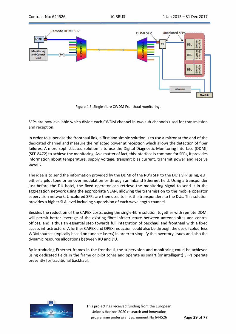
4.1.6. Performancemanagement Event counters can be used in conjunction with the monitoring to report the performance of the CPRI link, for measures of Mobile Key Performance Indicators (KPIs). The digital diagnostic information could be considered as an initial basis by which to achieve such a report.
4.2.1. Antennasitemonitoring Antenna site monitoring allows the mobile operator to supervise equipment at antenna sites which are under its responsibility. The antenna site alarms are collected by a controller located in the power cabinet at the antenna site. This controller is connected to the network via Ethernet, which allows remote monitoring of antenna site alarms and remote control of the antenna site power supply. Note that in one network model (other network models are discussed below this paragraph), a management channel for transport of these monitoring and control signals between the antenna site and the DU hotel has to be provided to the mobile operator by the fixed operator, in addition to the CPRI transport channels. This management channel is multiplexed /de‐multiplexed at both ends with appropriate equipment, as depicted in Figure 4.1. The multiplexing and de‐multiplexing could be achieved using several network resources, such as: wavelength (one pair of dedicated wavelengths), time (a dedicated field in the supported transport frame), frequency (pilot tones, is one example of such an overlay over CPRI transmission), spatial (a dedicated, regular fibre or core/mode in more advanced fibre structures). Another network model exists where the fibre provider only provides dark fibre and consequently the monitoring and control signals are under the full control of the RAN equipment. RAN sharing is also a third scenario, where a tertiary antenna operator collects the antenna supervision fields and emits reports to the mobile operator.
Contract No: 644526 iCIRRUS 1 Jan 2015 – 31 Dec 2017
Page 37 of 77
This project has received funding from the European
Union’s Horizon 2020 research and innovation
programme under grant agreement No 644526
Figure 4.1. Antenna site monitoring.
Linking supervision equipment (sensors, lightning arrester state, power supply, battery charge level, rectifier, fire alarms, door alarms, etc.) to the controller enables the supervision of the antenna sites as presented in Figure 4.1. In fact, the process takes place in 2 steps. Typically, three types of alarms can be generated by the controller in case of events trigged by inputs: Major alarm, minor alarm, lack of power. These alarms are sent to the supervision office in the CPRI via two RUs in order to offer some redundancy to the whole process. Then, in the second step, once the supervisor is warned, the supervisor can connect remotely to the controller using either the WDM channel dedicated to the antenna site monitoring or a signal in overlay of a CPRI channel. The supervisor can obtain details about the problem that has occurred and resolve it remotely if possible.
4.2.2. Fronthaulmonitoring Fronthaul monitoring allows the fixed operator to supervise the fixed infrastructure which transports CPRI traffic between DUs and RUs, and which is under its responsibility. Three solutions are possible for carrying out fronthaul monitoring:
Out of band monitoring using a dedicated management channel (different from the antenna site management channel)
In band monitoring within the overhead of protocols such as Ethernet.
In band monitoring via Connectivity Fault Management (CFM) as defined in IEEE802.1ag and ITU‐T Y.1731 utilizing CPRI Fast C&M channel
4.2.3. Outofbandmonitoring In the RAN, fronthaul transport can be achieved by means of passive multiplexing and de‐multiplexing of the CPRI links. The link supervision can then be realized with an active device located only at the DU hotel. This solution is shown in Figure 4.2 in the case of a dual fibre CWDM fronthaul transport system, where one fibre is dedicated to downlink and another fibre is dedicated to uplink.
Contract No: 644526 iCIRRUS 1 Jan 2015 – 31 Dec 2017
Page 38 of 77
This project has received funding from the European
Union’s Horizon 2020 research and innovation
programme under grant agreement No 644526
Figure 4.2. Dual‐fibre CWDM Fronthaul monitoring.
Using CWDM Multiplexers allows having a maximum of 18 channels with 20nm channel spacing from 1271 to 1611 nm. More wavelength channels are possible based on DWDM, but CWDM is the most appropriate technology for transceiver and multiplexer to fit the outdoor requirement (temperature range). In iCIRRUS we are interested in performing an evaluation and analysis of DWDM technology which allows the introduction of colourless equipment. Coming back to the CWDM scenario, one channel is dedicated to the fronthaul link supervision and another channel is dedicated to the antenna site monitoring. These channels are then connected to the aggregation network switch, using the appropriate VLAN, in order to be sent to the supervision office via the system. Fronthaul link supervision can be aided by comparing the inserted optical power in the dedicated channel and the received one, after having introduced a loop back on the RU side. This solution is simple to implement, reliable and outdoor compliant, but is not compatible with expected evolution to a single fibre architecture. The disadvantage of this solution lies also in the fact that one CWDM channel pair is used for this low traffic transmission. A more efficient solution should be proposed to save this wavelength pair. Indeed, with the emergence of bidirectional transceivers, it is now possible to achieve single fiber CWDM for the fronthaul transport as shown in the Figure 4.3.
Contract No: 644526 iCIRRUS 1 Jan 2015 – 31 Dec 2017
Page 39 of 77
This project has received funding from the European
SFPs are now available which divide each CWDM channel in two sub‐channels used for transmission and reception. In order to supervise the fronthaul link, a first and simple solution is to use a mirror at the end of the dedicated channel and measure the reflected power at reception which allows the detection of fiber failures. A more sophisticated solution is to use the Digital Diagnostic Monitoring Interface (DDMI) (SFF‐8472) to achieve the monitoring. As a matter of fact, this interface is common for SFPs, it provides information about temperature, supply voltage, transmit bias current, transmit power and receive power. The idea is to send the information provided by the DDMI of the RU’s SFP to the DU’s SFP using, e.g., either a pilot tone or an over modulation or through an inband Ethernet field. Using a transponder just before the DU hotel, the fixed operator can retrieve the monitoring signal to send it in the aggregation network using the appropriate VLAN, allowing the transmission to the mobile operator supervision network. Uncolored SFPs are then used to link the transponders to the DUs. This solution provides a higher SLA level including supervision of each wavelength channel. Besides the reduction of the CAPEX costs, using the single‐fibre solution together with remote DDMI will permit better leverage of the existing fibre infrastructure between antenna sites and central offices, and is thus an essential step towards full integration of backhaul and fronthaul with a fixed access infrastructure. A further CAPEX and OPEX reduction could also be through the use of colourless WDM sources (typically based on tunable lasers) in order to simplify the inventory issues and also the dynamic resource allocations between RU and DU. By introducing Ethernet frames in the fronthaul, the supervision and monitoring could be achieved using dedicated fields in the frame or pilot tones and operate as smart (or intelligent) SFPs operate presently for traditional backhaul.
Contract No: 644526 iCIRRUS 1 Jan 2015 – 31 Dec 2017
Page 40 of 77
This project has received funding from the European
Union’s Horizon 2020 research and innovation
programme under grant agreement No 644526
4.2.4. Inbandmonitoring
CPRI over Ethernet Encapsulating CPRI in Ethernet frames allows provision of native OAM. In fact, Ethernet allows link and performance monitoring. This Ethernet frame could be updated with more advanced Ethernet OAM functions such as IEEE 802.1ag and ITU‐T Y.1731. According to IEEE 802.1ag, Continuity Check Messages (CCM) are sent periodically at regular intervals. If no CCM is received within a specified interval, loss of continuity is detected, which implies that a link failure occurred. ITU‐T Y.1731 extends IEEE 802.1ag with mechanisms allowing the following KPIs measurements: Throughput, Frame loss, Frame delay, and jitter. Ethernet is very practical because of its large availability, its low cost and the fact that it can provide high levels of SLA monitoring. Nevertheless, encapsulating CPRI over Ethernet is not mature yet, may introduce additional delay, delay variation and L2 jitter, which will not be tolerated by CPRI. It should also be noted that in itself the use of an Ethernet Encapsulation can do little or nothing to address the bandwidth requirements of CPRI, and may, depending on the sophistication of the implementation, make this situation worse.
CPRI over OTN OTN (Optical Transport Network) also provides native OAM. It allows link and end‐to‐end performance monitoring thanks to the TCM (Tandem Connection monitoring) overhead. However, OTN mapping/de‐mapping could affect the performance (latency, jitter, synchronization) needed for CPRI.
CPRI over PON Native OAM is provided with OMCI (ONT Management and Control interface) in PON (Passive Optical Networks) systems. In the first PON generations, the GEM (Gigabit Encapsulation Method) framing has an impact on the CPRI performance, for example on latency and synchronization aspects. With the future TWDM NGPON2, it is possible to transport CPRI by using a new bandwidth allocation algorithm based on fixed time allocation. Another solution is to use an overlay signal (e.g. pilot tones) over each wavelength channel pair of TWDM and PtP NGPON2. In this case, no in band monitoring is provided, an out of band would be required.
Contract No: 644526 iCIRRUS 1 Jan 2015 – 31 Dec 2017
Page 41 of 77
This project has received funding from the European
Union’s Horizon 2020 research and innovation
programme under grant agreement No 644526
5 Proposalforanewfronthaul
5.1. Physicallayerfunctionalsubdivisions Previous chapters have shown that, while there are important advantages for deployment, using Ethernet in the fronthaul faces significant implementation challenges. In Chapters 2 and 3, it was found that the bit‐rate requirements and thus the transport costs become intolerably high, in particular taking into account that some operators have to lease fibres and that previous approaches reserved only the use of the wavelength domain for the distribution between different physical network elements. Chapters 2 and 3 highlighted significant delay and delay variation challenges when introducing switching equipment into the fronthaul path, due to the contention with other traffic passing the same node. Moreover, when transporting digitised radio signals, there is no statistical multiplexing gain. This means that, even if a user is receiving only several kbit/s of data, the whole waveform has to be digitized, leading to Gbit/s data rates, typically. Therefore, there is significant potential to reduce data rates in the fronthaul and to enable statistical multiplexing gains, which would be one of the key reasons for adopting switching equipment in the fronthaul. Burst‐like “packet‐switched” transmission, instead of continuous circuit‐switched transmission should be exploited to realise these advantages and to enable multiplexing with other traffic in the network. In this way, sharing of the network infrastructure between fronthaul and other services/operators becomes more easily achievable. Through statistical multiplexing, the available bandwidth in the fronthaul can be used more efficiently by dynamically allocating bandwidth resources to transmitting endpoints in an on‐demand basis (and not pre‐allocating based on potential peak data rates). This becomes possible as the transmissions are carried out at baseband and thus in bursts (as demand fluctuates). Buffering in the fronthaul (e.g. store and forward switching) can be used to “smooth out” peaks in the traffic and to keep links from overloading. Intelligence in the network can dynamically adapt the bandwidth utilization in each fronthaul link based on the temporal statistics of the individual streams. This is a different situation compared to that discussed in Section 3.2. Now, a switched Ethernet architecture can be used to its full potential, to provide statistical multiplexing gains by switching baseband data dynamically between smart DU pools and RUs.
5.1.1 Newfunctionalsplit The fundamental new paradigm in order to achieve statistical multiplexing gains is that instead of the sampled waveforms, the user data are exchanged between the DU and the RU. In the current fronthaul solution, all physical and MAC layer processing is located in the BBU. The so‐called functional split is currently made in front of the D/A, and after the A/D converter, in the down‐ and uplink directions, respectively. Only baseband filtering and (if required) some kind of time‐domain impairment compensation of, for example, IQ imbalance and nonlinear amplifiers, are implemented inside the RU. Moreover, the RU derives a precise clock signal from the continuous bit‐stream. All intermediate and radio frequencies (IF, RF) as well as the processing clock of the sampled waveform are generated inside the RU and they are all phase‐locked to the clock recovered from the bitstream. Obviously, a high precision is needed. Due to the continuous bit‐stream, a classical phase‐locked‐loop (PLL) can be implemented in the RU with a narrow bandwidth for the loop filter.
Contract No: 644526 iCIRRUS 1 Jan 2015 – 31 Dec 2017
Page 42 of 77
This project has received funding from the European
Union’s Horizon 2020 research and innovation
programme under grant agreement No 644526
In a future fronthaul, part of the signal processing can be shifted to the RU. This is denoted as the new functional split which becomes possible because in the current fronthaul solution there is already limited signal processing at the RU for impairment compensation and D/A and A/D interfaces. By increasing the signal processing at the RU, it is relatively straightforward to shift part of the functionality closer to the antenna site. The most obvious candidate for a such shift is the physical layer (PHY), as it contains the elementary waveform processing functionalities located immediately behind the current (i.e. “old”) functional split. The PHY processing is the most standardized part of mobile radio systems, unlike higher‐layer functions which, often, are partly implemented on a proprietary basis. By implementing parts of the PHY inside the RU, complexity is not greatly increased while data rates can be significantly lowered. There has been extensive research in recent years about how such a new functional split can be realized. An overview of the available literature is given in Table 5.1 and the existing evaluation results are summarized in Table 5.2.
Table 5.1. Literature Overview on new functional split.
Table 5.2. Summary of already available evaluation results.
Contract No: 644526 iCIRRUS 1 Jan 2015 – 31 Dec 2017
Page 43 of 77
This project has received funding from the European
Union’s Horizon 2020 research and innovation
programme under grant agreement No 644526
The main academic interest so far is in the achievable compression ratio and what error vector magnitude (EVM) is created after compression in case of losses. The compression ratio is inversely related to the maximal possible statistical multiplexing gain. The recent literature can be distinguished into point‐to‐point (P2P) time‐domain [39]‐[53] and frequency‐domain compression [54]‐[57], distributed compression techniques [58]‐[69] as well as dedicated work on the new functional split [70]‐[79]. The main idea in the P2P compression techniques is that radio resources in LTE are generally granted in the time‐frequency domain. Some such resources remain unused due to the reduced traffic load and in order to coordinate mutual interference. Fixed bandwidth schemes do not yield statistical multiplexing gain, and all time‐domain schemes are lossy. In the frequency domain, one could directly use the constellation points which enable the full compression gain without any loss. In that case, the signal structure is exploited, and this kind of compression is independent of the waveform processing and could also be applied, for example, to CDMA, when working in the code domain. This is a strong indication that a new fronthaul should transport the symbols from the currently selected modulation alphabet from the BBU to the RH in the downlink direction. It is more difficult to find a good location for the functional split in the uplink. Note, that it is the symbol decision which is known at the transmitter (but not at the receiver) which causes a large fraction of the possible compression gain in the downlink; this, however, is not available in the uplink. In a single‐input single‐output configuration, both hard and soft bits after the decoder can be used as an interface. In interference‐limited scenarios, cooperative signal processing among the base stations can be used to make better symbol decisions. Therefore, the sampled baseband signals after conversion to the frequency domain is probably the best choice in order to make better symbol decisions in the uplink. Concerning the new functional split, there has been significant work by Bell Labs [71] and in the European project IJOIN [74]‐[76]. Different split options have been discussed with the main finding that a split between MAC and PHY in the downlink and inside the PHY for the uplink might be most appropriate. The main advantage compared to compression is that these system‐internal new functional splits do not require additional delay due to compression and they can be lossless. In what follows, the recent findings in the literature are compiled and a first iCIRRUS proposal is presented as to how the functional split can be realized. In developing the initial iCIRRUS proposal, we take into account that there are important new developments, such as small cells, coordinated multipoint (CoMP) and massive MIMO [80] that must be accommodated by the new scheme. Therefore, the proposal is introduced in three steps, namely SISO first, and then including (massive) MIMO and finally also CoMP.
5.1.2. SISOlink
Recently, a new functional split between the DU/CO and the RUs, which no longer transports continuous streams containing sampled waveforms as end or start results of the baseband processing at the transmitter and receiver, respectively, has been discussed. Rather, intermediate signals are serialized and then transmitted as packets over Ethernet. This implies that more processing is moved from the DU pool/CO to the RU with the aim of reducing the bit‐rate and enabling statistical multiplexing gains with other traffic over the same Ethernet links.
Contract No: 644526 iCIRRUS 1 Jan 2015 – 31 Dec 2017
Page 44 of 77
This project has received funding from the European
Union’s Horizon 2020 research and innovation
programme under grant agreement No 644526
Figure 5.1. Signal processing in an LTE base station.
The signal processing in a LTE base station is shown in Figure 5.1. The base station is connected to the network over two logical links, S1 and X2. While S1 is the feeder link to the advanced gateway (aGW), which is the demarcation point between the network operator and the Internet, X2 is relevant for information exchange between base stations, e.g. during a handover. S1 and X2 often share the same physical network connection. The elementary LTE MAC and PHY processing functions are explained in the following. In the downlink, S1 data are first classified and the header information is used to store packets into user queues. Data transmitted in one 1 ms slot to one user is then packed into a so‐called transport block. After FEC, they are mapped onto the radio resources assigned to the user in the frequency domain. Even if the assigned resources are non‐contiguously mapped in the frequency domain, all data for one user that are contained in a single transport block are encoded jointly. A so‐called tuple is the set of bits yielding a single complex‐valued constellation point transmitted on a single radio resource element (i.e. one sub‐carrier in one OFDM symbol). Such constellations are fed block‐wise into an adaptive modulator, which supports variable constellation alphabets, and the resulting block of quasi‐analogue IQ signals is then fed into an inverse fast Fourier transform (IFFT). Finally, the cyclic prefix is added. Figure 5.1, shows how the user data are sorted into individual user queues. The scheduler selects data to be transmitted for each user during the next time slot. They are next fed jointly as one transport block into the FEC and then mapped together onto the assigned resources for each user, which is technically realized using a buffer memory. After all user signals to be transmitted in the next time slot have been arranged in the frequency‐time grid, the data are taken from the MAC to the PHY layer as 14 consecutive OFDM symbols to be transmitted over the next 1 ms. The CP is added and then the signals are transmitted via the radio frontend over the air. In the uplink chain, also shown in Figure 5.1, the cyclic prefix is removed and the channel is equalized in the frequency domain. The signal of a single user is then extracted from the overall received signal and passed through an inverse discrete Fourier transform, the block length of which is a multiple of 12 in LTE. The use of DFT spreading at the terminal side reduces the peak‐to‐average power ratio of the waveform and it exploits the multipath diversity in the channel. When demapping the tuples from the resulting signal constellations, both hard and soft bits are derived in order to inform the decoder about the reliability of hard decisions. Soft‐decision decoding yields better results, in particular in combination with bit‐interleaved coded modulation (BICM). Afterwards, the data are fed into the user queues, from where they are packed into Ethernet packets and sent to the aGW.
Contract No: 644526 iCIRRUS 1 Jan 2015 – 31 Dec 2017
Page 45 of 77
This project has received funding from the European
Union’s Horizon 2020 research and innovation
programme under grant agreement No 644526
With respect to the functional split, today the sampled waveform is transmitted over the optical link in CPRI/ORI. However, if we shift for instance the whole physical layer processing to the RU, as indicated by the orange dashed line, only the transport blocks need to be transmitted between DU/CO and RU, which leads to significantly reduced data rates. Moreover, the traffic is proportional to the data load; if there is no data for some users, less transport capacity will be needed in the fronthaul. In this way, statistical multiplexing gains become useful. Note that if the buffer memory is also placed in the RU, additional information where the data will be placed in the frequency‐time grid has to be sent along with the data which creates some overhead. However, because this information is also transmitted over the air to the terminal, where the correct data need to be decoded, such overhead is already minimized by means of user‐specific compression techniques defined in the LTE standard.
5.1.3. SupportformassiveMIMO One of the reasons to rethink the fronthaul design is the use of more and more antennas at the base stations, as is proposed for massive MIMO. By using CPRI, this would lead to a dramatic increase of the data rate, proportional to the number of antennas. However, these antennas are used to form beams partly carrying the same data towards an intended user. Therefore, it may be possible to also shift the required beam‐forming operation to the RU, as indicated in Figure 5.2. There is no fundamental change of the interfaces and thus the same functional split as in the case of Figure 5.1 can be applied. The scheduling information has to include additional information about the assigned beam, which is included in the precoding matrix indicator (PMI) in the LTE standard. If multiple beams are used in parallel to transmit data to multiple users (multiuser MIMO), then the data rate between MAC and PHY processor will be increased. The advantage is that often fewer streams are used compared to the number of antennas. This offers an additional degree of freedom for signal compression, leading to a further reduction of the fronthaul data rate.
Figure 5.2. The beamforming operation for massive MIMO can be shifted from the DU/CO to the RU in order to
reduce the data rate in the fronthaul.
5.1.4. SupportformassiveMIMOandCoMP Massive MIMO and Co‐ordinated Multipoint (CoMP) together is the most complex use case currently envisaged for future mobile radio systems. CoMP has been investigated in great detail to reduce the inter‐cell interference and to realize more consistently high data rates at the cell edge [81] The cellular system is considered as a distributed MIMO link where, in the downlink, the base stations are the inputs and the terminals the outputs. Base stations transmit cell‐specific pilot signals and terminals
Contract No: 644526 iCIRRUS 1 Jan 2015 – 31 Dec 2017
Page 46 of 77
This project has received funding from the European
Union’s Horizon 2020 research and innovation
programme under grant agreement No 644526
feedback their estimated channel state information (CSI). This information is exchanged among the base stations as is the data so that all base stations together become able to suppress the unwanted interference.
Figure 5.3. For CoMP, too, the required beamforming operation can be shifted from the DU/CO to the RU in
order to reduce the data rate in the fronthaul.
CoMP has been added to the system in Figure 5.3. It can be observed that locally, the data from other base stations are made available to be processed jointly with the desired data in the downlink. In this way, the desired signal quality can be improved, essentially by subtracting the interference from other cells. In the uplink, received signals from other cells are also made available via the X2 interface so that the interference can be reduced in a reciprocal manner. However, we need to take into account that now, besides the new fronthaul signals, the exchange of data and CSI between cells needs to be supported, which is commonly a task of the X2 interface over which the base stations are interconnected. Hence, in parallel to the scheduled user data, X2 information exchange becomes also a part of the fronthaul transport. Fortunately, it has been shown in [80] that this information exchange can be reduced if massive MIMO and CoMP are combined in future 5G systems.
5.2. MigrationtovirtualDUand/or5Garchitecture This Section discusses the changing role of the mobile base station, highlighting the opportunity for it to become based on generic IT equipment. We propose to illustrate this migration by four representative architectures. The first is the traditional one (Figure 5.4), used as a reference point, where there is only a backhaul network between the DU, which achieves the first level of traffic aggregation, and the IP network. Such backhaul and radio configurations have been already described in this document in Section 1.
Contract No: 644526 iCIRRUS 1 Jan 2015 – 31 Dec 2017
Page 47 of 77
This project has received funding from the European
Union’s Horizon 2020 research and innovation
programme under grant agreement No 644526
Figure 5.4. Traditional RAN architecture.
The second step of evolution concerns the centralisation of DU in a BBU hotel (main central office). This scenario is presently deployable with the proposed implementation by RAN companies. Sections 1 and 2 of this deliverable have presented this network evolution and its requirements. In this description, the backhaul network could be a local (internal) segment between the DUs and IP equipment which are co‐localised (or, at least, where the degree of centralization of IP equipment is much greater than that which is possible for separate BBUs due to latency constraints on the fronthaul). WDM is a common solution to share the fibre and Ethernet encapsulation of the fronthaul is also possible allowing for OAM (as discussed in Section 4).
Figure 5.5. DU centralised with fronthaul fiber shared based on WDM and Ethernet technologies.
The third scenario represents the fact that the resource allocation between DU and RU could be performed dynamically. In order to achieve this flexible allocation, a fronthaul switch allows interconnection over the medium between RUs and DUs. This switch could be based on Ethernet technology. Section 3 has discussed the potential of Ethernet implementations for such a network evolution and section 5.1, in particular, has highlighted the advantages brought to it by the new fronthaul functional split.
Contract No: 644526 iCIRRUS 1 Jan 2015 – 31 Dec 2017
Page 48 of 77
This project has received funding from the European
Union’s Horizon 2020 research and innovation
programme under grant agreement No 644526
Figure 5.6. DU centralised with dynamic pooling allocation between DUs and RUs.
The last scenario proposed in this network migration considers the fact that some DU functions could be virtualised inside IT equipment (localised in a data center). The RUs are still connected by fronthaul to a DU front end pool. This DU front end carries out the major signal processing functions which need dedicated hardware to be efficient in energy and time consumption. The DU front end pool is connected to virtual DUs which can carry out the radio resource allocation and upper layer functions. The hypothetical network between the DU front end pool and the virtual DUs is here termed “trunk‐haul”. Backhaul still exists between the IP core network and vDU pool. Fronthaul also exists still between DU front ends and RUs. This hypothetical architecture must be considered as a working scenario in the context of exploring 5G. No requirement could be proposed presently due to the current, exploratory stage of the definition of 5G architecture. The iCIRRUS project will consider in the future, collaborations with 5GPPP projects such as Xhaul and 5GXhaul to define such requirements.
Contract No: 644526 iCIRRUS 1 Jan 2015 – 31 Dec 2017
Page 49 of 77
This project has received funding from the European
Union’s Horizon 2020 research and innovation
programme under grant agreement No 644526
Figure 5.7. Potential 5G architecture including virtualisation.
5.3Summary To summarise this section, one of the most challenging topics of iCIRRUS will be the new functional split which can lead to:
True switching capability, load balancing and failover mechanisms in order to dynamically connect DUs to different RUs, thus enabling efficiency and resource optimization.
Bandwidth reduction. Existing CPRI does not make an optimal usage of the transport resources. There are two possible approaches to optimize the transport usage: Compressing CPRI I/Q data by resampling, rescaling and removing some unnecessary
parts of the signal, either as already defined by ETSI ORI, or through proprietary means.
Moving the optimum set of L1 processing to the RU side. The goal is to reduce the bandwidth in transport links in order to make use of a packet/frame‐mode transport network. This solution seems promising in terms of bandwidth reduction without adding too much complexity to the RU or reducing the coordination capability between adjacent cells.
Allowing the needed synchronization and control plane to use this new interface within a carrier network framework.
Contract No: 644526 iCIRRUS 1 Jan 2015 – 31 Dec 2017
Page 50 of 77
This project has received funding from the European
Union’s Horizon 2020 research and innovation
programme under grant agreement No 644526
6 IntelligentSONinthefronthaul The concept of self‐organising/optimising networks (SON) has been discussed extensively in many fora, with NGMN particularly instrumental in defining a set of use‐cases to clarify SON intentions and objectives [82]. We define “Intelligent SON” here as a move from a set of uses cases with frequently conflicting objectives to a coherent set of use‐cases that may be “supported in a harmonized way because they share common objectives,” [83], and, furthermore, where the focus is on subscriber‐centric optimisation of network performance.
Figure 6.1. Service dependent Hotsopts [84].
The importance of subscriber‐centric optimisation is illustrated by Figure 6.1, which shows that service demand, and indeed performance or quality, is spatially non‐uniform, and is differentiated by service type. What is not illustrated in the Fig. 6.1, but known from collected data, is that the demand and performance are time‐varying. Consequently, network optimisation that does not take account of subscriber location, traffic type, time, and subscription type really is not the most effective optimisation.
Contract No: 644526 iCIRRUS 1 Jan 2015 – 31 Dec 2017
Page 51 of 77
This project has received funding from the European
Union’s Horizon 2020 research and innovation
programme under grant agreement No 644526
Figure 6.2. 3GPP Management Reference Model showing SON architecture mapping [85].
Figure 6.1 illustrates the range of architectures that have been considered by the NGMN Alliance for implementing SON, which range from fully centralized to fully distributed, including a variety of hybrid architectures [86]. As mobile communication systems become larger and increasingly complex, a centralised system that pulls all data back to a single location may become increasingly difficult to achieve. However, network function virtualisation may reduce the cost and complexity of some aspects of such a centralised system as some previously distributed functionality might become co‐located. Additionally, as the proposed new front‐haul architecture sub‐divides DU and RU, a new degree of freedom for the optimisation is introduced and potentially another level of distribution in SON implementation may be exploited. The trade‐offs between different SON architectures given the proposed fronthaul split in iCIRRUS is for further study. The recent NGMN 5G White paper [83] suggests how SON may evolve with the advent of 5G. NGMN defined “5G design principles” that, selecting those that are relevant to “intelligent SON,” set out the intent to simplify operations and maintenance management involving: automation and self‐healing, probe‐less monitoring, collaborative management, integrated OAM functionality and carrier grade network cloud orchestration. Tables 6.1 and 6.2 present extracts of the White paper that summarise the aspects that are particularly relevant to a 5G architecture and that may incorporate at least some sub‐set of base‐stations that use the new front‐haul split that is being investigated in the iCIRRUS project.
Contract No: 644526 iCIRRUS 1 Jan 2015 – 31 Dec 2017
Page 52 of 77
This project has received funding from the European
Union’s Horizon 2020 research and innovation
programme under grant agreement No 644526
Table 6.1. NGMN Extracts relating to Network Deployment and Operation and Management.
NETWORK DEPLOYMENT, OPERATION AND MANAGEMENT Clause 4.6 of [83]
Potential areas of interest for iCIRRUS “Intelligent SON”
Ease of deployment
plug and play, self‐configuration, optimization and healing
adapt to diversified network configurations, such as ideal/non‐ideal,
fixed/wireless backhaul/fronthaul
1. Introduction of this additional functional split creates opportunities at least to self‐configure the “legacy” functional split or the “new” functional split between the BBU and RRU. For example, the functional split may be may be autonomously configured at initial deployment based on x‐haul capability and expected service requirements
Operations awareness
to access, monitor and process … instantaneous network conditions to
optimally connect and route user traffic in a dynamic manner
2. The introduction of a new front‐haul split creates opportunities for self‐configuration and, if dynamic, opportunities to optimally share n/w functionality between BBU and RRU on a case‐by‐case basis considering overall air‐interface needs (for example in support of interference coordination and management), backhaul capability/requirements, and also self‐healing demands
securely collect information that can enhance user experience and service
experience (e.g. speed, location) via data analytics
3. The need for security of collected information is also an interesting aspect to consider in the context of “intelligent SON,” the depth of analysis appropriate for iCIRRUS is subject for study. Additionally, the capabilities of front‐haul in‐terms of latency and jitter may interact, in a positive manner, with the ability of the system to estimate user speed and location using radio information, thereby creating a means to enhance user and service experience
healing and self‐optimising network) shall be supported in a harmonized way because
they share common objectives
4. This is supporting of 2. and an initial requirement is to conduct a literature review
user/application level QoS/ QoE monitoring capability shall be supported by UE and network and controlled at network /
service management level i.e., to extend the monitoring to the application level in order to be able to introduce metrics that can provide a characterization of the user experience (e.g., for a video streaming
service)
5. This will likely require exchange of extra information about user/application level QoS/ QoE and enhancement/definition of associated interfaces. This would be interesting to explore but in the context of iCIRRUS only a high‐level analysis is likely to be feasible.
Contract No: 644526 iCIRRUS 1 Jan 2015 – 31 Dec 2017
Page 53 of 77
This project has received funding from the European
Union’s Horizon 2020 research and innovation
programme under grant agreement No 644526
Table 6.2. NGMN Extracts relating to Technology and Architecture: Radio.
TECHNOLOGY AND ARCHITECTURE: RADIO Clause 5.3.1 of [83] Potential areas of interest for iCirrus “Intelligent SON”
Enable cost‐effective dense deployments
the system should be able to cope with:
unplanned, chaotic deployments and unexpected interference
adapt to the availability of different types of backhaul and fronthaul and to have automated configuration
optimization and healing capabilities
ability to self‐manage interference and load balancing
6. As above in 1. and 2. This may require exchange of extra information about the network and enhancement/ definition of
associated interfaces
Coordinate and cancel
interference
Both massive MIMO and CoMP transmission rely on the availability of
channel state information to realize their full potential
5G network architecture should
therefore support the flexible location of coordination functions depending upon the transport network capabilities, supporting a trade‐off between the benefits of wide‐area optimization in
more central locations with the potentially detrimental impact of
backhaul delay on resource allocation
7. As above in 2.
The 5G network must also be designed to exploit any feasible interference cancellation methods, such as non‐
orthogonal multiple access (NOMA) with advanced receivers, where they offer
useful performance benefits
8. As above in 2.
The new proposed architecture introduces a new degree of freedom into the network as to where radio functions may be placed. This may be exploited to achieve the objective of optimising performance within the constraints of the available network intra‐connectivity ‐ whether that may fall into the category of backhaul/midhaul or fronthaul. To exploit such extra freedom, a SON system, whether centralised, distributed or hybrid, requires new or enhanced interfaces from which to extract new or enriched information and through which to command configuration changes. For example, considering Table 6.3, to “ease deployment,” information is required about available backhaul options, their capability and the ability to configure/reconfigure their use. On the other hand, “operations awareness,” requires information about network conditions to route traffic in a dynamic manner and to provide information that can be used to enhance user experience such as user speed or location, potentially allowing dynamic control of the fronthaul functional split to optimise performance or to respond to network incidents, whilst keeping within physical limits and constraints of various aspects, for example the fronthaul bandwidth. Table 6.3 provides a summary of the opportunities for Intelligent SON in a 5G network considering the requirements outlined for 5G by the NGMN.
Contract No: 644526 iCIRRUS 1 Jan 2015 – 31 Dec 2017
Page 54 of 77
This project has received funding from the European
Union’s Horizon 2020 research and innovation
programme under grant agreement No 644526
Table 6.3. Intelligent SON opportunities in a split front‐haul architecture.
NGMN reference Opportunity
NGMN Information required
Summary of possible actions
iCirrus: Potential areas of interest for iCirrus “Intelligent SON”
Ease of deployment
ideal/non‐ideal fronthaul type (“Ideal” or near‐ideal corresponds to timing requirements
defined in Table 2.6, as such performance allows, for example, coherent
combining, whereas non‐ideal corresponds to
performance where, for example, coherent
combining is no‐longer feasible all the way down
to the requirements outlined in Section
1.2.3.2
Configure fronthaul.In cloud RAN scenario, instantiate initial RAN
service to serve initial user population, modify surrounding cells to
compensate if required.
i. Determine x‐haul availability/capability and
RAN requirements ii. Self‐configure x‐haul for
initial deployment
Operations awareness
Instantaneous network conditions
Connect and route user traffic in a dynamic
manner, for example by modifying the serving cell or cells to balance load, mitigate interference, etc
iii. determine x‐haul availability/performance
iv. determine air‐interface/MAC demand
v. Autonomously configure BBU‐RRU split and x‐haul vi. Investigate interactions
between x‐haul reconfiguration and potential serving cell
modifications
RF information to determine speed/location
Enhance user experience and service experience. For example, to select physical layer, modulation scheme, appropriate to that speed and the radio conditions in
that location
vii. Opportunity to investigate interaction
between x‐haul configuration and mode/accuracy of
speed/location estimation from RF data. Expect that only a limited investigation could be considered to be within the scope of iCirrus
Operation Efficiency
Flexible, programmable and real time network
and service management processes, relying on autonomic/self‐
management functions (self‐configuring, self‐diagnosing, self‐healing and self‐optimising network) shall be supported in a
harmonized way because they share common
objectives
Harmonised optimisation for set of KPIs such that a configurable set of KPIs is optimised dependent on various factors such as
service type, SLAs in place, operator policy
viii. Opportunity to investigate new types of harmonised KPIs relevant to SON. Expect that only a limited investigation could be considered to be within
the scope of iCirrus
Contract No: 644526 iCIRRUS 1 Jan 2015 – 31 Dec 2017
Page 55 of 77
This project has received funding from the European
Union’s Horizon 2020 research and innovation
programme under grant agreement No 644526
Information to determine QoS/QoE at UE and
network level
Optimise radio parameters, bearer type, connectivity
architecture
ix. as vii. above
Enable cost‐effective dense deployments
Identify interference and effects of unplanned
(subscriber self‐installed) deployments
For example, subscriber self‐installed cells.
Re‐configure to avoid interference, and to
balance load
x. as iii. above. The front‐haul configuration can
impact the performance of inter‐cell co‐ordination
and interference cancellation. Additionally, different co‐ordination schemes have varying
latency requirements on the exchange of assistance
data.
Coordinate and cancel
interference
Local radio need for MIMO/COMP, available
fronthaul
Re‐configure fronthaul to permit required synch
tolerance
xi. Interaction between x‐haul split and
availability/performance of CoMP/M‐MIMO as vii.
above
Local need for NOMA Re‐configure to enable NOMA and exchange required information
xii. As xi above
The objective from an iCIRRUS viewpoint is to investigate the opportunities that become available with the new fronthaul split, as outlined in Table 6.3, and to determine what information needs to be extracted from the network, what new or enhanced interfaces are required to do this, what type of performance indicators may be calculated from this information and the associated configuration changes to be pushed to the network and the associated interfaces required for that. The areas that will be addressed in subsequent deliverables and the depth of analysis appropriate for iCIRRUS within those deliverables are for further study.
Contract No: 644526 iCIRRUS 1 Jan 2015 – 31 Dec 2017
Page 56 of 77
This project has received funding from the European
Union’s Horizon 2020 research and innovation
programme under grant agreement No 644526
7 D2DandD2InetworkinginaC‐RAN
7.1 Introduction Device to Device (D2D) communication underlaying cellular networks brings numerous benefits to current cellular networks including proximity gain, frequency reuse gain and hopping gain. Device to infrastructure (D2I) communication refers to the communication between mobile devices and the network core infrastructure, including RRH and BBU pool in the case of iCIRRUS. In traditional cellular networks, all communications between any two mobile devices will go through D2I communications. That is, the data between the two mobile devices will be transmitted from one mobile device to the core infrastructure and forwarded to the other mobile device. D2D communication indicates that two mobile devices are allowed to communicate directly when they are in proximity. D2D communication has been considered as a substitute for device to infrastructure (D2I) communication to reduce latency, power consumption and improve system spectrum efficiency, as the transmission distance and resource for data transmission are greatly reduced. However, there are some vital, different requirements for D2D communication compared to D2I communication; for instance, the proximity between transmitter and receiver is important. So, not all D2I links within a cell can be substituted by D2D links. Furthermore, to achieve the optimal system performance within a limited and licenced spectrum, central control from a network controller (e.g. BBU pool) is needed to select the use of D2D or D2I for the communication mode to achieve the best quality of service (QoS) to all active users. An intelligent C‐RAN architecture permits the joint operation and management of D2D and D2I communications, using emerging mm‐wave technologies to permit very high data rates over relatively short distances. New networking topologies (e.g. ad‐hoc meshing) and functionalities (e.g. local distributed caching) in addition to the important cloud functionalities associated with a C‐RAN are expected. Optimization with respect to load balancing of traffic distributed to the D2D and mesh networks, and the added control protocol overhead will also be possible. Frequencies will be shared by different D2D pairs and D2I links, so that the network signaling overhead and delay needs to be better understood, in order to find the optimum balance between centralised and distributed (in UE) management of the virtualized network, with the additional need of hardware‐based monitoring support. In order to avoid strong interference and to guarantee the transmission of D2D data, different frequency bands may be used for the signaling and data transmission: e.g. backhauling of D2D communications may use D2I control channels over lower‐frequency LTE‐A bands, while D2D data transmission uses 60 GHz. However, the interaction between D2D and D2I communications at different frequency bands will result in extra control overhead in the BBU pool, which also needs to be investigated.
Contract No: 644526 iCIRRUS 1 Jan 2015 – 31 Dec 2017
Page 57 of 77
This project has received funding from the European
Union’s Horizon 2020 research and innovation
programme under grant agreement No 644526
7.2 Resourceallocation
7.2.1 D2D/D2Iresourceallocationinatraditionalcellulararchitecture Currently, in traditional cellular networks, there are two resource sharing methods between D2D and D2I communication [87], [88].
Orthogonal sharing method: licenced spectrum is divided into two non‐overlapping parts and is separately assigned to D2D and D2I communication. In other words, D2D and D2I communications do not share the same spectrum within a cell. Using an orthogonal sharing model for D2D communications is also called dedicated D2D communications.
Non‐orthogonal sharing method: licensed spectrum can be shared by both D2D and D2I links. Therefore, intra‐cell interference exists. Note that the intra‐cell interference contains cross‐layer interference (between D2D users and D2I users) and inter‐D2D co‐channel interference (between D2D pairs which use the same spectrum).
The advantage of the orthogonal sharing is that the resource allocation is much simpler than that for the non‐orthogonal sharing due to the fact that only the channel status information (CSI) of D2D links is needed. Compared to the orthogonal sharing, a proper resource allocation for non‐orthogonal spectrum sharing can generally achieve better spectral efficiency and energy efficiency. However, the CSIs for all D2D links, but also for all devices sharing the same spectrum are needed, which may cause an overwhelming signalling overhead and system complexity. Considering the complexity, in a dense user scenario, it may be more practical to assign dedicated spectrum to multiple D2D links based on the short transmission range, in order to be able to harvest the highest spatial diversity gain. The use of mm‐waves, e.g. 60GHz, for transmission, due to its short range propagation characteristics, may be particularly suitable for dedicated D2D transmission rather than D2I transmission (see section 7.3). Thus, only inter D2D co‐channel interference exists within one cell coverage. The resource allocation for dedicated D2D communications underlaying traditional cellular networks can be divided into two categories, namely distributed and centralised resource allocation, as discussed in the following subsections.
7.2.1.1Distributedresourceallocation In this case, if the communication meets the proximity requirement, then the active users will form the D2D links. After that, the network (i.e. the BBU pool) will assign a block of resources as a whole to these D2D links (activated based on proximity) for them to share for their data transmission. Then, each D2D link selects individual resources for its own communication in an autonomous way. The network would have no control on the resource utilization of each individual D2D link, and thus the intra‐cell interference can only be managed in a statistical way. Furthermore, due to the competition between D2D links caused by the lack of central control, energy efficiency among D2D links is poor.
Observation 1: For distributed resource allocation, large CSI collection and computation processing are needed at the user side and overall system performance (energy efficiency and spectrum efficiency) may be degraded.
Contract No: 644526 iCIRRUS 1 Jan 2015 – 31 Dec 2017
Page 58 of 77
This project has received funding from the European
Union’s Horizon 2020 research and innovation
programme under grant agreement No 644526
7.2.1.2Centralizedresourceallocation In this case, the BBU pool should assign resources for D2D transmission to each individual D2D link. Note that it is possible that no resource is assigned to any specific D2D link (according to the interference environment and individual D2D link status) to achieve the global optimum spectrum efficiency for the whole network as well as energy efficiency for each individual D2D link. More stable connections for D2D communications can be expected, because the inter D2D co‐channel interference can be controlled by centralised resource allocation as much as possible. Further, more flexible resource allocation due to different D2D link user scenarios (e.g. video streaming, real‐time gaming, advertising etc.) are expected, as the resource allocation can be performed dynamically. However, the signalling cost and the computation processing latency at BBU pool would be high if the number of D2D links is large.
Observation 2: For centralized resource allocation, a large amount of CSI collection is needed at the user side and greater feedback and control signalling is needed at the BBU pool through the fronthaul. Greater computational processing is needed at the BBU pool.
7.2.2 Semi‐distributedresourceallocationinaC‐RANarchitecture Considering the huge overhead of centralised resource allocation and the low efficiency of the distributed resource allocation, semi‐distributed resource allocation is proposed in iCIRRUS in the C‐RAN architecture. It is noted that in a small area, spectrum should not be reused due to the strong co‐channel interference. Thus, the active D2D users within the network can be separated into different groups according to their geographical locations, and reuse of the spectrum can be based on a frequency reuse pattern among different groups. In the traditional network layout (e.g. an urban macro‐cell scenario), due to the lack of location information, grouping the UEs becomes challenging. However, in a C‐RAN scenario, multiple RRHs are deployed within one urban macro‐cell coverage area. For each cellular user, one RRH or several RRHs will be used for accessing the EPC. Thus, the location of the users can be roughly perceived by the RRH identification and can be used to group the UEs.
Proposal 1: The RRH ID should be added to each user packet at the RU side before being transmitted to the DUs, and further understood by the BBU pool, as shown in Figure 7.1.
Contract No: 644526 iCIRRUS 1 Jan 2015 – 31 Dec 2017
Page 59 of 77
This project has received funding from the European
Union’s Horizon 2020 research and innovation
programme under grant agreement No 644526
FronthaulRU
RU
RRH ID
Link CSI
RU
Link CSI + RRH ID
BBU PoolMain CO
NetworkController/Evolved
Packet Core
DU Front End
DU Front End
DU Front End
Figure 7.1. Uplink signaling for proposal 1.
FronthaulRU
RU
RRH ID
Resource allocation result
RU
BBU PoolMain CO
NetworkController/Evolved
Packet Core
DU Front End
DU Front End
DU Front End
Figure 7.2. Downlink signaling for proposal 1.
Contract No: 644526 iCIRRUS 1 Jan 2015 – 31 Dec 2017
Page 60 of 77
This project has received funding from the European
Union’s Horizon 2020 research and innovation
programme under grant agreement No 644526
Based on the RRH ID, within the coverage of the same RU, the same frequency cannot be reused by different D2D links. However, the network can assign the same spectrum to D2D links in the coverage areas of different RRHs, and the global interference level can be roughly controlled by the BBU pool to guarantee the QoS. At a D2D user, only the CSI of each D2D link needs to be collected and fed back to the BBU pool instead of all interference channels. Hence the feedback signalling, both from a user to its RU and from the RU through the fronthaul to the BBU pool, can be greatly reduced. The resource allocation for D2D links within one RRH coverage can be locally performed to further reduce the signalling from RU through fronthaul to the BBU pool. In that case, each RU should collect local CSI information for the D2D links under its coverage and generate statistical values for some system parameters (e.g. the number of D2D links) and feed back to the BBU pool, as shown in Figure 7.3. The BBU pool should perform the resource allocation for each RRH instead of each D2D link. That is, how to reuse the frequency among different groups are determined at the BBU pool based on the current, statistical status of the network. At the RRH side, based on the assigned resource from the BBU pool and the CSIs collected from D2D links, resource allocation for each D2D link will be performed, and the allocation result will be sent from the RRH to each of the D2D links. Proposal 2: The resource allocation function should be divided into two parts, as shown in Figure 7.3: 1) frequency reuse pattern design function located in the BBU pool; 2) local resource allocation function located at each RU.
Fronthaul
RU
RU
D2D counter
Link CSI
RU
Statistic value(number of D2D pairs)
Resource Allocation
BBU PoolMain CO
NetworkController/Evolved
Packet Core
DU Front End
DU Front End
DU Front End
Frequency reuse pattern
Figure 7.3. Uplink signaling for proposal 2.
Contract No: 644526 iCIRRUS 1 Jan 2015 – 31 Dec 2017
Page 61 of 77
This project has received funding from the European
Union’s Horizon 2020 research and innovation
programme under grant agreement No 644526
Fronthaul
RU
RU
D2D counter
Resource allocation result
RU
RRH spectrum assignment
Resource Allocation
BBU PoolMain CO
NetworkController/Evolved
Packet Core
DU Front End
DU Front End
DU Front End
Frequency reuse pattern
Figure 7.4. Downlink signaling for proposal 2.
7.3 D2Dcommunicationsatmm‐Wavebands As mentioned in section 7.2, in order to avoid strong interference and to guarantee the transmission of D2D data, the transmission can be expected to be enabled by mm‐wave technologies. Millimetre‐wave standards are already in existence to address the developing mm‐wave application areas, particularly operating at 60 GHz, which is an unlicensed band available worldwide [89]. For example, the 802.11ad standard was formed in January 2009 to address the 60 GHz market. The WiGig specification, which aims to achieve multi‐gigabit wireless communication in the 60 GHz band, has also emerged as an 802.11ad amendment, building on the existing 802.11 standard providing interoperability with the 2.4 GHz and 5 GHz bands based on the existing 802.11b/a/g/n and 802.11ac standards. It is anticipated that by 2017, IEEE 802.11ad will be an integral part of many consumer electronic devices such as personal computers, tablets and mobile phones. The 24‐GHz band is designated an instrumentation, scientific and medical (ISM) band and is license‐free. It is also attracting growing interest for high‐capacity wireless communications, suitable for integration into future 5G networking architectures [90]. Transmitting in the 60‐GHz band enables WiGig and 802.11ad to offer significantly higher data rates than the previous standards; by using four 2.16‐GHz wide channels, more than 7 GHz of spectrum is available. Channel 2 is available in all regions and is therefore used as the default channel. 802.11ad
Contract No: 644526 iCIRRUS 1 Jan 2015 – 31 Dec 2017
Page 62 of 77
This project has received funding from the European
Union’s Horizon 2020 research and innovation
programme under grant agreement No 644526
also defines both single carrier (SC) modulation and orthogonal frequency division multiplexing (OFDM) modulation. Unlike 802.11ac, WiGig and 802.11ad use beamforming to enable communications over longer distances, even though signal attenuation is relatively high in the 60 GHz band (as compared to the 2.4 GHz or 5 GHz ranges). However, in this case high gain antennas can be deployed to improve the signal strength at the receiver. Such high gain antennas, mostly phased‐array antennas, utilize beamforming to create beams in a particular direction allowing the transmitted power to be focused. Because the antenna size in the 60 GHz band is very compact, small and competitive antenna arrays can be used, with the 802.11ad standard supporting real‐time beamforming. The 802.11ac standard is suitable for longer‐range high‐throughput applications, such as in‐home wireless LAN and compressed multimedia wireless display, since the regulatory transmitter power and power consumption requirements limit applicability to different use cases and since the obstruction loss at 5 GHz is lower than at 60 GHz. Multi‐gigabit 802.11ac is more appropriate for both line of sight (LoS) and non line of sight (NLoS) wireless applications where portability is not a bottleneck. 802.11ac chipsets are already being deployed in mobile phones, PCs, laptops, and mobile devices, where smart phones use the technology for high‐speed networking, HD video, and videoconferencing. 802.11ad is therefore most appropriate for LoS, room‐scale, low‐cost, short‐range, and very high throughput applications, such as in‐room uncompressed and lightly compressed multimedia wireless displays, sync data/file transfer, etc. Low cost 60 GHz high gain antennas featuring small sizes can also be realized for D2D and D2I applications, such as for small‐cell backhaul networking.
7.4 Summary
In this context, D2D and D2I algorithms need to be defined to optimally exploit, offload, and intelligently coordinate available fixed/mobile converged infrastructure resources, and also provide differentiated Quality of Service/Experience (QoS/E), particularly with respect to latency, jitter, energy efficiency (these aspects already as discussed within this document), as well as the cloud‐based issues such as application processing and offloading. Key Performance Indicators (KPIs) including D2D coverage distances [91], D2D discovery time (synchronization scheme dependent), D2D setup latency (solution dependent, e.g. the level of network assistance), feedback latency, e.g. HARQ feedback latency (less than 1 millisecond), D2D link throughput and device battery consumption (total D2D radio power consumption should be lower than the cellular radio power consumption) are all aspects that will be studied during the course of the iCIRRUS project, with the associated requirements being more precisely defined as the D2D and D2I technologies in the C‐RAN context become better understood.
Contract No: 644526 iCIRRUS 1 Jan 2015 – 31 Dec 2017
Page 63 of 77
This project has received funding from the European
Union’s Horizon 2020 research and innovation
programme under grant agreement No 644526
8 MobilecloudnetworkinginaC‐RAN
The focus of this section is on the Mobile Cloud in the iCIRRUS architecture. The benefits of the mobile cloud are two fold: 1) Computation related, 2) Communication related. Section 8.1 discusses the technical issues. Then, Section 8.2 presents the iCIRRUS Mobile Cloud and how it addresses these issues.
8.1 Technicalissues
8.1.1 Computation The mobile devices are not just used for making mobile phone calls as was intended when they were invented. They are embedded into users’ lives due to advancements in functionality, which assist daily activities. Mobile devices come with sophisticated operating systems. On top of that, users may install computationally heavy applications. These give rise to compute related issues, as listed below: 1. Lack of processing power in mobile device to execute code in time. 2. Executing compute intensive code on mobile device leads to battery drain. To support the increasing, computationally heavy applications and services, new mobile devices come packed with hardware that becomes more powerful each year. As a result the need for exploring alternative methods for reducing mobile energy consumption while increasing computational performance has become crucial.
8.1.2 Communication Mobiles are made to communicate, whether it is with other mobile devices in the same vicinity (D2D), or with another mobile device via the wireless network infrastructure or with servers on the Internet. Device‐to‐Device communication uses the existing cellular spectrum for establishing connection between the devices and to exchange the data itself. Mobile users share data such as User Generated Content (UGC) through the Internet. Much of the available spectrum is already used and licensed to mobile operators. Due to increasing number of mobile users and the average amount of data that is transmitted via cellular networks, there is a great need to save spectrum and/or better utilise existing spectrum.
8.2 Mobilecloudarchitecture The iCIRRUS architecture permits the mobile cloud to perform compute and communication tasks, such that network resources in the mobile cloud and wireless resources in the C‐RAN are allocated optimally. This section introduces the reader to mobile cloud operations and to high‐level concepts that joint resource allocation will be used for. The assumptions that have been made when designing the proposed architecture are as follows:
Contract No: 644526 iCIRRUS 1 Jan 2015 – 31 Dec 2017
Page 64 of 77
This project has received funding from the European
Union’s Horizon 2020 research and innovation
programme under grant agreement No 644526
Mobile operators have the capacity in the infrastructure to facilitate computing and storage resources.
The connected devices are smart mobile devices.
The mobile users trust the network operators to store and handle mobile applications and user data.
The special feature of the architecture introduced is that it gives the operator the ability to store and handle user data and other computational tasks of its subscribers within the mobile operator’s network. Therefore, the operator is able to offer value added customised services tailored to each user. The iCIRRUS architecture introduces a layer of computational resources on top of the conventional C‐RAN architecture. A pool of computational resources called the Mobile Cloud is formed and is placed immediately beside the BBU pool, as shown in Figure 8.1. In the Mobile Cloud there are virtual machines (VMs) that are able to perform computational tasks and to store user data. To be able to run mobile executable code, the VM has to have an environment in which mobile code can be executed. For example, for executing Android mobile code, the virtual machine should have an Android(‐type) operating system. It is hoped that in the future the proprietary mobile OS developers such as Apple and Microsoft will also have their own versions of the mobile OS made available for mobile operators to be used on conventional VMs. Due to the aforementioned characteristics of the virtual machine, it is referred to as a “Clone”.
Figure 8.1. General iCIRRUS Network Architecture showing Mobile Cloud.
A subscriber of an operator that has deployed this type of proposed architecture is able to sign up for a package that enables clone facilities. Moreover, each mobile subscriber may have its own dedicated clone in the Mobile Cloud. When a mobile user connects to its network, a clone will be created and the storage volume that contains the user’s data will be mounted to the created clone. Once the bootstrapping process is done, the subscriber may benefit from the services that are enabled by the clone. The benefits of having such a Clone for the user and also for the operator are discussed in sections 8.2.1 and 8.2.2.
Mobile Cloud
Mobile Clone (Android VM)
C"RAN&
RRH&
RRH&
BBU&
X2/S1&Interface&
backhaul&
Contract No: 644526 iCIRRUS 1 Jan 2015 – 31 Dec 2017
Page 65 of 77
This project has received funding from the European
Union’s Horizon 2020 research and innovation
programme under grant agreement No 644526
8.2.1 Computation Due to attributes such as elasticity and availability, cloud computing becomes a good solution that can be considered when it comes to solving computation related issues [92]. The notion of a clone occurs when a virtual machine in a cloud has the capabilities of its real, mobile device counterpart. Executing mobile applications, storing data, communicating (virtually) are some of the identified capabilities. Compute offloading Clone enabled mobile devices may offload their partitioned code to their dedicated mobile clones [93], [94]. With the clone’s operating system being the same as its mobile device, the code that is transferred from the mobile device can be executed without making any modifications, which makes the process faster. The decisions as to when and what to offload is made by a decision‐making entity that resides in the mobile device. Parameters such as network channel state that is obtained from the C‐RAN, local task execution time and clone task execution time are among the parameters that are used when making offloading decisions. Other types of computational tasks Instead of using the clone to help increase the speed of the applications running on the device by executing partitioned code chunks, we can use the clone to run applications or provide other services for the mobile users. Examples of such services are as follows: Video transcoding ‐ When a client is requesting a video from a video source, the video is transcoded according to the requested video quality before streaming, if adaptive video streaming is used. Besides the capabilities of the client, the network state has a principal influence on the video quality when it is transcoded. The mobile client decides the best video streaming quality at a given time. Considering that the clones reside next to the BBU pool and have access to up‐to‐date mobile network state information, video transcoding can be done in the clone depending on the client’s network state. This eliminates the decision‐making stages that are carried out in the mobile device. Security services ‐ If all or some of the mobile traffic is transferred through the mobile clone, all packets thus transferred can be scanned for Malware, Viruses and other security threats. Scanning for viruses involves using a great deal of CPU power. In addition, the security guard software that is installed has to be up to date for identifying new threats. If the scanning is done in the clone, the CPU time spent scanning is moved to the clone while the security software can be updated regularly without using mobile data or CPU power. Service Personalisation ‐ There are many services that are offered on the Internet but the majority are largely generalised to fit all users or they require the users to log into their systems for personalising their services. Similar services that already exist today use online user profiles to achieve such results where users are required to sign‐up beforehand. Often such profiles only work with its registered services. The clone can be considered as its user’s universal online profile or the user’s virtual personality. The user data and application data that is stored in the clone can been used to learn about the user. In this scenario, the clone can be used as an intermediate node which can amend all content/traffic that goes through it to fit user’s preferences. For example: when a user requests for a news feed from the Internet, the news feed is personalized before it reaches the user’s device, such that the user’s preferred or most viewed news categories are given priority to appear on top of the page. In addition, if a user is looking at a webpage, the unwanted content or advertisements on the webpage can be stripped out or replaced with the user’s preferred content or the advertisements can be tailored to a user’s given profile.
Contract No: 644526 iCIRRUS 1 Jan 2015 – 31 Dec 2017
Page 66 of 77
This project has received funding from the European
Union’s Horizon 2020 research and innovation
programme under grant agreement No 644526
Compression ‐ Compression has been used widely as it is a widely known technique to reduce the size of the data. Compression done in a clone is useful in cases where data that is downloaded from the Internet has to be compressed before storing in the clone to save storage. Additionally, the data that is downloaded through the clone to the mobile device will have then been compressed, so that the amount of traffic is reduced. However, this means decompression has to be done in the mobile device.
8.2.2 Communicationoffloading With a clone, all communications do not have to occur directly from one device to the other. Since all users have their own clones, when one has to send data to another, the sender’s clone can transfer the data to the receiver’s clone, assuming that the sender already possesses the data to be sent in its clone [95]. This turns D2D communication to C2C (Clone to Clone) communication. An example of this could be mobile social networks where users (i.e., UEs) store their user‐generated content (UGC) on their clones rather than on a centralised server (like Facebook). Current social networks are centralised which gives rise to data privacy concerns. Mobile social networks enabled by clones store content on the content owner’s clone. We can consider three scenarios as below: One sender ‐ One receiver. In this scenario, user A (sender) may upload some of its data (content) that is intended to be shared with others in the future to its dedicated clone. User B (receiver) is interested in what user A possesses, so he requests user A’s content. Once a connection has been established between users A and B for sharing the requested data, user A sends the requested content to user B’s clone. Finally, user B receives the requested content from its own clone as shown in Figure 8.2. When considering this scenario, there are not many benefits for the network operators, nor for the users. The reason is the similarly to the D2D communication scenario, as wireless spectrum has been used, once to upload the data and also again to download the data at the receiving end.
Figure 8.2. C2C: One sender one receiver scenario.
One sender ‐ many receivers of same content to their own clone at the same time. The user A (sender) has content that many other users are interested in. All interested users request the same content from user A. Once the receivers have established connections with user A to receive data, the sender uploads the content to his clone. Then, the sending clone sends content to all the receiving users’ clones. In this scenario, we can save wireless spectrum since the sender only uploads the content once when sharing the same content with many users at the same time. Whereas, in a
Contract No: 644526 iCIRRUS 1 Jan 2015 – 31 Dec 2017
Page 67 of 77
This project has received funding from the European
Union’s Horizon 2020 research and innovation
programme under grant agreement No 644526
conventional D2D system, the sender may upload n times to send data to n receivers. This scenario is depicted in Figure 8.3.
Figure 8.3. C2C: Many receive same content to their own clone.
One sender ‐ many receivers of same content from the sender’s clone directly. This scenario is very similar to the previous scenario as shown in Figure 8.4, with the only difference being that the sender does not have to send the content to receivers’ clones. The sender’s clone allows all other receivers to obtain content directly from his clone. This scenario eliminates the second Clone to Clone data transfer step; the benefit of this is that by reducing clone‐to‐clone communication, we reduce traffic within the mobile cloud.
Figure 8.4. C2C many receive from sender's clone.
Contract No: 644526 iCIRRUS 1 Jan 2015 – 31 Dec 2017
Page 68 of 77
This project has received funding from the European
Union’s Horizon 2020 research and innovation
programme under grant agreement No 644526
9 Conclusions This deliverable document has described the initial architecture proposed for the iCIRRUS C‐RAN with intelligent, Ethernet‐based fronthaul, a C‐RAN architecture which enhances 5G mobile network objectives such as D2D networking and mobile cloud networking. The arguments for using Ethernet in the fronthaul have been presented, and can be summarised as follows:
1. The use of ubiquitous technology and equipment, lowering costs (especially capital expenditure)
2. The sharing of equipment with fixed access network infrastructures, leading to further cost savings
3. The use of OAM functions which are already a standard part of carrier Ethernet implementations
4. The use of a switched fronthaul network to dynamically and efficiently use the bandwidth of the available links
These advantages could be realised by using native Ethernet transport of CPRI type signals or by mapping the radio samples into Ethernet frames directly. The latter may reduce overheads, since the CPRI framing overhead is removed, and may also have advantages as Ethernet is already specified at much higher bit‐rates than CPRI. The deliverable has also described how one of the most serious challenges facing fronthaul transport of sampled radio waveforms (whether in CPRI or Ethernet) is the extremely high bit rates that would be needed for 5G systems with wider bandwidths, multiple antenna techniques and joint transmission schemes. Thus, a new functional split is proposed in which baseband data is transported in the fronthaul, instead of sampled radio waveforms. This “light” fronthaul, as it transfers user data on a needs basis rather than continuous radio streams, brings into play the full advantages offered by argument 4 above – the switched fronthaul network can utilise statistical multiplexing gains to truly optimise efficient use of bandwidth. A remaining challenge for an Ethernet fronthaul comes from timing, latency and jitter considerations. CPRI links were TDM‐based and synchronous, inherently providing timing references to the antenna sites. Introducing any form of frame‐based transmission, with switching equipment, into the fronthaul can destroy this timing relationship. An initial survey of work being undertaken in this area by standards bodies and others has been carried out and presented. The future work on the iCIRRUS fronthaul will consider the following aspects:
1. The precise functional split which can provide the optimum balance between the amount of data sent over the new, light fronthaul and the performance of the radio system, including accommodation of joint transmission and reception strategies, MIMO and CoMP.
2. The provision of timing and synchronisation to enable, for example, joint transmission, especially over the new, light fronthaul.
3. Ethernet networking strategies so that bandwidth utilisation of the fronthaul can be managed and controlled, including through SDN, to meet efficiency and synchronisation demands.
4. The provision of OAM over the fronthaul, efficiently using the Ethernet functionality. 5. Network virtualisation and the inter‐working of fronthaul transport with backhaul and
midhaul networks. 6. Intelligent monitoring in and of the fronthaul, to inform and optimise performance,
networking and OAM.
Contract No: 644526 iCIRRUS 1 Jan 2015 – 31 Dec 2017
Page 69 of 77
This project has received funding from the European
Union’s Horizon 2020 research and innovation
programme under grant agreement No 644526
The potential of the new transport and modified functional split arising from our analysis of network expectations provides an extra degree of flexibility for self‐optimised networking (SON). The following challenges are seen to arise from this flexibility, i) collection of data on transport capability/ performance and its impact on radio performance, ii) collection of data on subscriber behaviour and subscriber QoE/QoS, iii) analysis of the exploitation of such data to drive network organisation/ optimisation/ healing. As the RAN evolves and merges with the IT world with virtualisation and cloud aspects, it is crucial that we recognize the importance of building on the cooperation between infrastructure, software and platform. Based on this joint and coordinated network model, we open the door to a joint operation and management of the Device to Device (D2D) and Device to fixed Infrastructure (D2I) communications connected to this new network. In this deliverable, the resource allocation schemes for D2D/D2I underlaying both traditional and C‐RAN architectures were discussed. For D2D/D2I resource allocation underlaying a C‐RAN architecture it was proposed that an RRH ID should added to user packets at the RU side and checked by the DU, and that the resource allocation function should be divided into a frequency reuse part at the DU pool and a local function based at the RU. The D2D/D2I resource allocation can be significantly improved by the functional split between DU and RU. However, the system performance gain and optimal solution for the functional split needs to be further analysed and evaluated, to gain a better understanding of the network design requirement for the new fronthaul and C‐RAN architecture for 5G. It was further proposed that the 60‐GHz frequency band may prove more suitable for D2D transmission rather than D2I transmission due to the relatively high path loss. MIMO technologies (including path diversity approaches), as well as the intrinsic directivity of the 60‐GHz radiation, as well as advanced antenna design (e.g. discoidal, arrays etc.) could be advantageously used, as required, to achieve the desired networking performance targets. All these aspects are still areas of active research in what is still a relatively immature technology. Finally, a mobile cloud placed in the iCIRRUS network to benefit the network operators and the mobile subscribers has been introduced. The mobile cloud benefits from the high degree of centralisation at the DU pool, locating the cloud resources adjacent to the pool. In this project we propose to study the following aspects: i) the design of a compute offloading framework and algorithm for reduced mobile energy consumption and for efficient code execution. ii) a Joint/Cooperative resource allocation scheme between DU and Mobile cloud. iii) the identification of applications for communication offloading. This deliverable has to be considered as an initial iCIRRUS consensus on RAN evolution (5G) requirements.
Contract No: 644526 iCIRRUS 1 Jan 2015 – 31 Dec 2017
Page 70 of 77
This project has received funding from the European