Page 1
IIUM Engineering Journal, Vol. 13, No. 2, 2012 Abid and Ullah
143
INVESTIGATION OF RESIDUAL STRESSES AND
DISTORTION IN WELDED PIPE-FLANGE JOINT OF
DIFFERENT CLASSES
MUHAMMAD ABID AND SATTAR ULLAH
GIK Institute of Engineering Sciences and Technology, Topi, Pakistan.
[email protected]
ABSTRACT: Pipe and flange joints are commonly used in petrochemical, nuclear and
process industries. Commonly, welding is used to make these joints which produce
residual stresses and distortions. These stresses have detrimental effects on the structural
integrity and service performance of the welded pipe joints. The objective of this study is
to investigate the residual stresses and distortions during Gas Metal Arc Welding of pipe
of schedule 40, nominal diameter 200 mm with different ANSI flanges of class numbers
150, 300, 600, 900, 1500, and 2500. Welding parameters including: voltage, current and
heat as inputs were selected based on the literature available. The behaviour of the
flanges of different classes is also discussed. In addition, the finite element methodology
presented, in this paper, can be helpful for developing welding procedures for a range of
pipe flange welded joint sizes in order to control the residual stresses and deformations.
This will lead to optimised performance during bolt up and operating conditions.
ABSTRAK: Paip dan sambungan flan biasanya digunakan dalam industri petrokimia,
nuklear dan proses. Kimpalan menghasilkan tegasan sisa dan herotan, yang memberikan
kesan yang merbahaya ke atas integriti struktur dan prestasi servis sambungan kimpalan
paip. Objektif kajian ini adalah untuk mengkaji tegasan sisa dan herotan ketika kimpalan
arka logam gas paip berjadual 40, diameter nominal 200mm dengan flan ANSI yang
berbeza kelas # 150, 300, 600, 900, 1500, dan 2500. Parameter kimpalan termasuklah;
voltan, arus dan haba input yang dipilih berdasarkan literatur sediada. Kelakuan flan
yang berbeza kelas telah dibincangkan. Kaedah elemen finit yang dibentangkan adalah
berguna dalam membangunkan prosedur kimpalan bagi julat saiz kimpalan flan paip
unutk mengawal tegasan sisa dan canggaan i.e. bagi mengoptimakan prestasi ketika bolt
up dan sedang beroperasi.
KEYWORDS: finite element; residual stresses; distortion; welding; pipe-flange joint;
different classes
1. INTRODUCTION
The earliest welding technology can be traced to ancient time when forge welding was
utilized in weapons. Electric fusion process is reported in 1782 in Germany by
Lichtenberg [1], and electric arc welding process is reported in nineteenth century. The
process of analytical determination of welding effect such as residual stresses and
deformation started in mid 1940s and substantial work is observed in 1950s. This further
led to the numerical modeling of heat flow and structural response during welding.
Inherently, thermo-mechanical analysis of welding is non-linear due to non-linear thermal
and structural material properties.
An analytical study by Vaidyanathan et al. [2] initially provided a method for the
determination of residual stresses in thin walled cylindrical shells welded by single pass
full penetration welds. Later work was extended [3] for a variety of the welding
Page 2
IIUM Engineering Journal, Vol. 13, No. 2, 2012 Abid and Ullah
144
conditions, including multi-pass weld, partial penetration of weld and different materials
for base and filler metals. Rybicki et al. [4-7] performed 2D FEA study for two pass weld
for circumferential welding of stainless steel pipes. Jonsson and Josefson [8] performed
experimental work in order to find transient strain and residual stresses in pipe. Josefson et
al. [9] performed a comparative FEA study of 2D and 3D elements (solid and shell) to
determine transient and residual stresses in a single-pass butt-welded pipe. Lindgren and
Karlsson [10] developed a 3D model using shell elements to study deformation and
stresses in welded thin walled pipes. For heat source distribution, analytical solution
presented by Rosenthal [11] for moving line heat source in thin plates was used and
temperature dependant material model was taken from Karlsson and Josefson [12,13].
Results were compared with [14] and were found in good agreement. It was concluded
that 2D model may give reasonable results for residual stresses, but 3D model is necessary
for transient and residual strains. Karlsson and Josefson [15] also analyzed a complete 3D
FE model with solid elements for welding simulation of a pipe.
The effect of welding distortions and residual stresses on load carrying capacity of the
pipe was studied by Troive et al. [16], using 3D FEA model for thin walled pipe with
thermo-elasto-plastic shell elements with the same material model as used by Karlsson and
Josefson in [15]. In order to find transient temperature history Rosenthal analytical
solution [17] for a heat source with uniform strength along a line through the thickness of
a plate was used. Troive et al. [18] extended their work for pipe-flange welding and
concluded that the effect of geometrical size of pipe and flange is slightly greater than the
one used in [16]. A new dental-foam method was developed for experimental
measurement of axial distortions in flange. Teng and Chang [19] using axi-symmetric FE
model for pipe-pipe joint, studied the effect of pipe diameter and wall thickness on
residual stresses and results were found in agreement with the Rybicki et al. [20-21]. Abid
and Siddique [22-35] has performed a detailed parametric welding simulation of pipe-
flange joints and have studied the effect of welding, geometric and other parameter on
residual stresses and welding distortion. They concluded that the effect of decreasing
current is almost similar to the increasing welding speed, at least for the range of
parameters used in his study. They concluded that the main factor is the heat input per unit
length of weldment, which has positive effect on the magnitude of the residual stresses and
zone of influence. Pipe diameter has significant effect on the magnitude of residual
stresses as well as on the zone of influence. Pipe wall thickness has negative effect on the
magnitude of the residual stresses because pipe of smaller wall thickness has low stiffness
and more prone to the radial shrinkage resulting bending stresses. They concluded that any
change in tack weld location alters the axial displacement and tilt of the flange face.
Regarding root gap opening it is found that root gap should be a minimum, just to meet the
need of weld penetration. Large root gap increases lateral shrinkage and results in higher
axial displacement and flange face tilt. Structural constraints were modeled representing
welding fixture in girth welding of pipe-flange joints and to determine the effect of
different constraints with the objective to minimized flange deformations. Abid and Jawad
[36-39] have performed detailed three dimensional finite element analyses for multi pass
welding. They have described the details of welding sequence; inter pass cooling and
effect of different parameters on residual stresses and deformations.
2. WELDING PARAMETERS
Low carbon steel with chemical composition 0.18% C, 1.3% Mn, 0.3% Si, 0.3% Cr,
0.4% Cu is used in present work. Temperature dependant material properties are taken
from Karlsson and Josefson [14]. As welding applies much localized heating on material,
Page 3
IIUM Engineering Journal, Vol. 13, No. 2, 2012 Abid and Ullah
145
therefore they change the metallurgy, fluid flow, deformation and stresses of a material,
however, in the present work, change in microstructure and fluid flow of a material is not
taken in to account, and effect of welding on mechanical property is considered only. For
conductivity, Goldak [40-41] assumed a value of 120 W/m◦C in the liquid range for low
carbon steel. In order to model fluid flow (stirring) effect on the thermal field, thermal
conductivity is given an artificial rise to 230 kJ/mK at solidus temperature, as suggested
by Anderson [42]. Temperature dependent specific heat value used in [42] is taken and
latent heat of fusion of 260 kJ/kg is specified for low carbon steel. Young’s modulus of
12.4 GPa is used, however even lower value of 1 GPa is also reported in [43]. The values
for both the bulk modulus and Poisson’s ratio are taken constant after 1200 oC.
3. FINITE ELEMENT MODELING
Fig. 1: (a) 3D solid model without bolt holes, (b) Tack weld geometry.
Weld neck flanges of ANSI Class #150, 300, 600, 900, 1500, and 2500 [44] are
analyzed during welding with pipe of length 200 mm of schedule 40 to observe residual
stresses and displacement behavior during welding. Welding and geometrical parameters
used are; Arc voltage 28 Volts; welding current 315 Amp; arc efficiency 85%; surface
area 90 mm2; welding speed 6.25 mm/sec; heat intensity 98 W/mm
2; nominal pipe
diameter 200 mm and pipe thickness 8 mm. Single pass GMAW welding using root gap of
1.2 mm is employed and bolt holes in the flange ring are neglected. Element length along
radial direction and along circumferential direction is 2 mm and 9.44 mm respectively.
Element length in the axial direction in melted and heat effected zone is 1.42 mm.Weld
tack location is 90 and 270 degree from weld start position as suggested by Abid and
Siddique [23-25] and each tack length is 18.9mm with thickness of 4 mm. Tack welds also
act as the boundary condition and restrain free body motion of the flange. Consequently,
the stiffness of the tack welds (more precisely tack ring) is reduced to a very small value
and permits unrestrained motion of the flange during the thermal cycle. For structural
boundary condition all the node at the far end of the node is constrained to model pipe
effect. 3D FEA takes about 113 sec to complete circumferential weld with the welding
sequence divided into 120 equally spaced solution steps of 0.941 sec each. The stepped
load option of ANSYS [45] is used for effective application of the thermal load during
each load step. After extinguishing the arc, 48 load steps of different lengths are used for
cooling of the weldment. It takes about 52 min to return to the ambient temperature of 27 oC. Three dimensional pipe flange joint model and tack weld geometry is shown in Fig. 1.
Page 4
IIUM Engineering Journal, Vol. 13, No. 2, 2012 Abid and Ullah
146
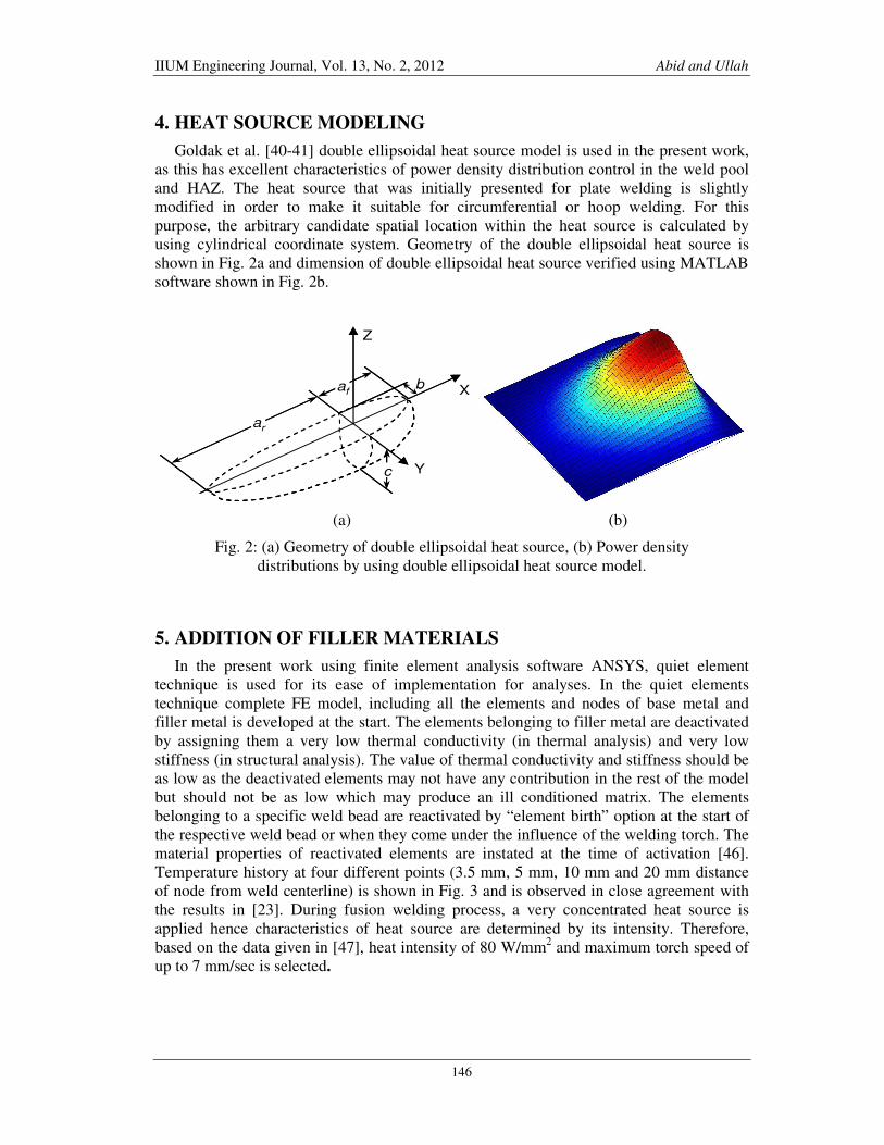
4. HEAT SOURCE MODELING
Goldak et al. [40-41] double ellipsoidal heat source model is used in the present work,
as this has excellent characteristics of power density distribution control in the weld pool
and HAZ. The heat source that was initially presented for plate welding is slightly
modified in order to make it suitable for circumferential or hoop welding. For this
purpose, the arbitrary candidate spatial location within the heat source is calculated by
using cylindrical coordinate system. Geometry of the double ellipsoidal heat source is
shown in Fig. 2a and dimension of double ellipsoidal heat source verified using MATLAB
software shown in Fig. 2b.
(a) (b)
Fig. 2: (a) Geometry of double ellipsoidal heat source, (b) Power density
distributions by using double ellipsoidal heat source model.
5. ADDITION OF FILLER MATERIALS
In the present work using finite element analysis software ANSYS, quiet element
technique is used for its ease of implementation for analyses. In the quiet elements
technique complete FE model, including all the elements and nodes of base metal and
filler metal is developed at the start. The elements belonging to filler metal are deactivated
by assigning them a very low thermal conductivity (in thermal analysis) and very low
stiffness (in structural analysis). The value of thermal conductivity and stiffness should be
as low as the deactivated elements may not have any contribution in the rest of the model
but should not be as low which may produce an ill conditioned matrix. The elements
belonging to a specific weld bead are reactivated by “element birth” option at the start of
the respective weld bead or when they come under the influence of the welding torch. The
material properties of reactivated elements are instated at the time of activation [46].
Temperature history at four different points (3.5 mm, 5 mm, 10 mm and 20 mm distance
of node from weld centerline) is shown in Fig. 3 and is observed in close agreement with
the results in [23]. During fusion welding process, a very concentrated heat source is
applied hence characteristics of heat source are determined by its intensity. Therefore,
based on the data given in [47], heat intensity of 80 W/mm2 and maximum torch speed of
up to 7 mm/sec is selected.
af
ar
c
b
Z
X
Y
af
ar
c
b
Z
X
Y
Page 5
IIUM Engineering Journal, Vol. 13, No. 2, 2012 Abid and Ullah
147
Fig. 3: Temperature histories.
6. RESULTS AND DISCUSSION
6.1 Residual Stresses
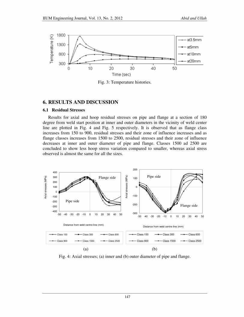
Results for axial and hoop residual stresses on pipe and flange at a section of 180
degree from weld start position at inner and outer diameters in the vicinity of weld center
line are plotted in Fig. 4 and Fig. 5 respectively. It is observed that as flange class
increases from 150 to 900, residual stresses and their zone of influence increases and as
flange classes increases from 1500 to 2500, residual stresses and their zone of influence
decreases at inner and outer diameter of pipe and flange. Classes 1500 ad 2500 are
concluded to show less hoop stress variation compared to smaller, whereas axial stress
observed is almost the same for all the sizes.
(a) (b)
Fig. 4: Axial stresses; (a) inner and (b) outer diameter of pipe and flange.
-400
-300
-200
-100
0
100
200
300
400
-50 -40 -30 -20 -10 0 10 20 30 40 50
Axia
l str
esses (
MP
a)
Distance from weld centre line (mm)
Class 150 Class 300 Class 600
Class 900 Class 1500 Class 2500
-300
-200
-100
0
100
200
-50 -40 -30 -20 -10 0 10 20 30 40 50
Axia
l str
esse
s (
MP
a)
Distance from weld centre line (mm)
Class 150 Class 300 Class 600
Class 900 Class 1500 Class 2500
Pipe side
Flange side
Pipe side
Flange side
Page 6
IIUM Engineering Journal, Vol. 13, No. 2, 2012 Abid and Ullah
148
(a) (b)
Fig. 5: Hoop stresses on (a) inner and (b) outer diameter of pipe and flange.
(a) (b)
Fig. 6: Axial displacements on: (a) inner, (b) outer circumference at flange end.
6.2 Axial Flange Displacement
Axial flange displacement plots at inside and outside diameters of flange ring along
360degree location are plotted in Fig. 6. It is observed that as flange class increases from
150 to 1500, axial displacement decreases from weld start position (zero degree) up to first
tack (90 degree). Axial displacement increases from 90 degree i.e. first tack to 270 degree
i.e. second tack. For flange class 2500, axial displacement slightly decreases up to
30degree and then rapidly increases up-to 225 degree and then decreases almost to the
same value at the start at 360degree location both at the inside and outside diameters of
flange ring.
-250
-150
-50
50
150
250
-50 -40 -30 -20 -10 0 10 20 30 40 50
Ho
op
str
esse
s (M
Pa
)
Distance from weld centre line (mm)
Class 150 Class 300 Class 600
Class 900 Class 1500 Class 2500
-200
-100
0
100
200
300
-50 -40 -30 -20 -10 0 10 20 30 40 50
Ho
op
str
esse
s (M
Pa
)
Distance from weld centre line (mm)
Class 150 Class 300 Class 600
Class 900 Class 1500 Class 2500
1.1
1.2
1.3
1.4
0 60 120 180 240 300 360Axi
al D
isp
lacem
ent (m
m)
Angle from weld start positioton (Degree)
Class 150 Class 300
Class 600 Class 900
Class 1500 Class 2500
0.8
0.9
1
1.1
1.2
1.3
1.4
1.5
1.6
0 60 120 180 240 300 360
Axia
l d
ispla
ce
men
t (m
m)
Angle from weld start posititon (Degree)
Class 150 Class 300
Class 600 Class 900
Class 1500 Class 2500
Pipe side Flange side Pipe side Flange side
Page 7
IIUM Engineering Journal, Vol. 13, No. 2, 2012 Abid and Ullah
149
7. CONCLUSION
Based on extensive parametric 3D finite element simulations for a range of flange
classes, following conclusions are made;
• Stress variation on the flange side is more prominent due to its dimensional
variation, whereas, on the pipe side a slight variation in all the classes is observed.
• Overall axial flange displacement along 360 degree is quite obvious and is the key
finding to avoid gasket crushing, bolt scatter, bolt relaxation and hub flange
yielding due to flange rotation. This ultimately affects sealing of the gasketed
flanged pipe joints.
• Bolt holes in the flange ring are not modeled in this parametric study. However,
with bolt holes in the flange, axial displacement may increases. Hence detailed
analysis considering bolt holes in the flange will be performed in future work.
FE methodology presented can be helpful for developing welding procedures for a
range of pipe flange welded joints for controlled residual stresses and deformations for
optimized performance during bolt up and operating conditions.
REFERENCES
[1] “The Procedure Handbook of Arc Welding.” 14th Ed. The James F. Lincoln Arc Welding
Foundation, Cleveland, USA, 2000.
[2] Vaidyanathan S., Todaro A.T., and Finnie, I. “Residual Stresses due to
CircumferentialWelds.” ASME J. Engineering Material and Technology 1973: 239-242.
[3] Rybicki, 8.F., Schmueser, D.W., Stonesifer, R.W., Groom, J.J., and Mishler, H.W., “A
Finite
[4] Element Model for Residual Stresses and Deflections in Girth-Butt Welded Pipes.”Journal
of Pressure Vessel Technology 100(August, 1978): 256-262.
[5] Rybicki, E. F., and Stonesifer, R.8. “An Analysis of Weld Repair Residual Stresses for an
[6] Intermediate Test Vessel.” Joumal of Pressure Vessel Technology 102(August 1980):323-
31.
[7] Rybicki, 8.F., and McGuire, P.A. “A Computational Model for Imp,roving Weld Residual
[8] Stresses in Small Diameter Pipes by Induction Heating.” Journal of Pressure Vessel
Technology 103(August, 1981): 294-9.
[9] Rybicki, E.F., and McGuire, P.A. “The Effects of Conduction Heating Conditions on
Controlling Residual Stresses in Welded Pipes.” Joumal of Engineering Materials and
Technology 104 October, 1982: 267-273.
[10] Jonsson, M. and Josefson, B.L. “Experimentally Determined Transient and Residual
Stresses in Butt-Welded Pipes.” Journal of Strain Analysis 23.1(1988): 25-31.
[11] Josefson, L., Jonsson, M., Karlsson, L., Karlsson, R., Karlsson, T. and Lindgren L.E.
“Transient and Residual Stresses in a Single-Pass Butt-Welded Pipe.” ICRS-2, Nancy,
France (1988): 23-25.
[12] Lindgren L.E. and Karlsson, L. “Deformations and Stresses in Welding of Shell
Structures.”International Journal Numerical methods in Engineering 25(1988): 635-55.
[13] Rosenthal, D. “The Theory of Moving Heat Source and its Application to Metal Treatment.”
Transaction ASME, 1946.
[14] Karlsson, R.I. and Josefson, B.L. “Three Dimensional Finite Element Analysis of
Temperature and Stresses in a Single-Pass Butt-Welded Pipe.” ASME Joumal of Pressure
Vessel Technology 12(1990): 76-84.
[15] Karlsson, L., Jonsson, M., Lindgren, L.8., Nasstrom, M. and Troive, L., “Residual Stresses
and Deformations in a Welded Thin-Walled Pipe.” Proceedings of ASME Pressure Vessel
Page 8
IIUM Engineering Journal, Vol. 13, No. 2, 2012 Abid and Ullah
150
and Piping Conference, Weld Residual Stresses and Plastic Deformation, Hawaii,
173(1989): 7-14.
[16] Jonsson, M. and Josefson, B.L. “Experimentally Determined Transient and Residual
Stresses in the Butt-Welded Pipes.” Journal of Strain Analysis 23.1(1988): 25-31.
[17] Karlsson, R.I. and Josefson, B.L. “Three Dimensional Finite Element Analysis of
Temperature and Stresses in a Single-Pass Butt-Welded Pipe.” ASME Joumal of Pressure
Vessel Technology 12(1990): 76-8.
[18] Troive, L., Lindgren, L.E. and Jonsson, M. “Axial Collapse Load of Girth Butt-Welded
Pipe.”Proceedings of First International Symposium on Thermal Stresses and Related
Topics, Japan: Shizuoka University, Hamamatsu 1995: 565-568.
[19] Rosenth I, D. “Theory of Moving Heat Source and its Application to Metal Treatment.”
Transaction ASME, 1946.
[20] Troive, L., Niisstrijm, M. and Jonsson, M. “Experimental and Numerical Study of Multi-
Pass Welding Process of Pipe-Flange Joint.” ASME Pressure Vessel Technology
120(1998):244-52.
[21] Troive, L. and Jonsson, M. “Numerical and Experimental Study of Residual Deformations
Due to Double-J Multi-Pass Butt-Welding of a Pipe-Flange Joint.” Proceedings of IEMS'94
(1994 Annual International Conference on Industry, Engineering and Management
Systems), Florida USA: Cocoa Beach (1994): 107-l 14.
[22] Teng T.L. and Chang, P.H. “A Study of Residual Stresses in Multi-Pass Girth-Butt Welded
Pipes.” International Journal Pressure Vessels and Piping 74(1997): 59.
[23] Rybicki, E.F., McGuire, P.A., Merrick, 8., and Wert, E. “The Effect of Pipe Thickness on
Residual Stresses due to Girth Welds.” Journal of Pressure Vessel Technology 104(1982):
204-9.
[24] Rybicki, E.F., and Stonesifer, R.B. “Computation of Residual Stresses Due to Multipass
Welds in PipingSystems.” Journal of PressureVesselTechnology 101(1979): 149-154.
[25] Muhammad Siddique. “Experimental and Finite Element Investigation of Residual Stresses
and Distortion in Welded Pipe and Flange Joints.” Ph.D Thesis, GIK Institute Topi, KPK,
Pakistan. 2005.
[26] Muhammad Abid and Muhammad Siddique. “Welding Simulations for Pipe Flange Joints.”
VDM Verlag Dr.Muller, printed in the U.S.A. and in te U.K. (2009): 200.
[27] M. Abid, M.Siddique and R.A Mufti. “Prediction of Welding Distortion and Residual
Stresses in a Pipe Flange Joint Using Finite Element Technique.” Modelling and Simulation
in Material Science and Engineering (2005): 454-70.
[28] Abid, M. and Siddique, M., Numerical Solution to Study the Effect of Tack Weld and Root
Gap on Welding Deformation and Residual Stresses of Pipe Flange Joint. 82(2005): 860-71.
[29] M. Siddique, M. Abid, H. F. Junejo, R. A. Mufti. “3D finite element simulation of welding
residual stresses in pipe-flange joints: effect of welding parameters.” Journal of Material
[30] Science Forum 490-491 (2005): 79-85.
[31] M. Abid" M. Siddique, R.A. Mufti. “Prediction of welding distortions and residual stress in
pipe, flange joint using finite element technique.” Journal of Modelling and Simulation in
Materials Science and Engineering l3 (2005): 455-70.
[32] M. Abid, M. Siddique. “Finite Element Simulation of Tack Welds in Girth Welding of Pipe
Flauge Joint'nn.” Journal Acta Mechanica, 178. 1-2(2005): 5344.
[33] M. Abid, M. Siddique. “Numerical simulation to study the effect of tack welds and root gap
on welding deformations and residual stresses of a pipe-flange joint.” Intemational Journal
of Pressure Vessels and Piping 82(2005): 860-71.
[34] Muhammad Abid, Muhammad Siddique. “Numerical Simulation of the effect of Constraints
on Welding Deformations and Residual Stresses in a Pipe-Flange Joint.” Journal of
Modelling and Simulation in Materials Science and Engineering, lnstitute of Physics, l3
(2005): 919-33.
[35] M. Siddique, M. Abid. “Numerical Simulation of mechanical stress relieving in a multi-pass
GTA girth welded pipe-flange joint to reduce fGSCC.” Journal of Modelling and Simulation
in Materials Science and Engineering, Institute of Physics 13 (2005): 1383 1402.
Page 9
IIUM Engineering Journal, Vol. 13, No. 2, 2012 Abid and Ullah
151
[36] M. Siddique, M. Abid, H. F. Junejo. “3-D Finite Element Simulation of a single pass
buttwelded pipe-flange joint.” 2nd International Mechanical Engineering Congress (SIMEC
2003), Karachi, Pakistan, (Sep 26th - 28th 2003):1-12.
[37] M. Siddique, M. Abid, H. F. Junejo, R. A. Mufti. “Three dimensional finite element
simulation of welding residual stresses in pipe-flange joints: effect of welding parameters.”
7th Inflation Conference on Residual Stresses in China llurlle l4-t7, 004: 1-8.
[38] M. Siddique, M. Abid and R. A. Mufti. “Simulation of welding distortions and Residual
Stresses in pipe-flange joint using finite element Technique: Comparison of 2D and 3D
models.” International Mechanical Engineering Conference (IMEC2004), Kuwait
(December 5-8, 2004): 614-91.
[39] Muhammad Abid, Muhammad Siddique. “A Study of Welding Deformations and Residual
Stresses in a Pipe-Flange Joint: Effect of Constraints.” Tehran International Congress on
Manufacturing Engineering (TICME2005), Tehran, Iran (December l2-l5, 2005): 1-8.
[40] M. Jawad Qami. “3D Thermo-Mechanical Finite Element Analysis of Residual Stresses and
Distortions due to Multi-Pass Welding in Pipe Flange Joints.” MS Thesis. GIK Institute
Topi, KPK, Pakistan. 2008.
[41] M. Abid and M. J. Qarni. “Numerical investigation of residual stresses and distortions due
to multi-pass welding in a pipe flange joint.” Process. Mech Part E: Journal Process
Mechanical Engineering, 2241.4(2010): 253-67.
[42] M. Abid and M. J. Qarni. “3D thermal finite element analysis of single pass girth welded
low carbon steel pipe-flange joints.” Turkish Journal Engineering Environment Sciences
33(2009): 2841-293.
[43] Muhammad Abid, Muhammad Jawad Qarni. “3D Thermo-Mechanical Finite Element
Analysis of Residual Stresses and Distortions due to Multi-pass Welding in Pipe Flange
Joints.” 3rd National Seminar on Welding Science and Technology, Islamabad Pakistan
(July 2729, 2009): 1-9.
[44] Goldak, J., Bibby, M., Moore, J., House, R., Patel, B. “Computer Modeling of Heat Flow in
Weld.” Metallurgical Transactions B, 17(1986): 587-600.
[45] Goldak, J., Chakravarti, A. and Bibby, M. “A new Finite Element Model for Heat Sources”
Metallurgical Transactions B, 15(1984): 299-305. vol. 15 B, pp. 299-305, 1984.
[46] Andersson, B.A.B. “Thermal Stresses in Submerged-Arc Welded Joint Considering Phase
transformations.” ASME Journal. Engineering Material and Technology 100(1978): 356
[47] 62. Lindgren, L.8. “Runnemalm, H. and Niisstrtim, M.O., Simulation of Multipass Welding
of a Thick Plate.” International Journal Numerical Methods Engineering 44(1999): 1301-
16.
[48] British Standards Institution. “Circular Flanges for Pipes, Valves and Fittings.” BS 1560:
Section
[49] 3.1(1989). ANSYS Workbench Version 11. Engineering Data, Material Library, 2008.
[50] Lindgren, L.E. and Hedblom, R. “Modeling of Addition of Filler Material in Large
Deformation
[51] Analysis of Multipass Welding.” Communication .in Numerical Methods in Engineering
17(2001): 647-51.
[52] Kelly Ferjutz, Joseph R. Davis, Nikki D. Wheaton. “ASM Handbook, Welding, Brazing and
Soldering.” 10th ed. Ohio: ASM International 6.