37
IPC/IPX PowerStation Series Hardware User Guide Parker Hannifin 5500 Business Park Drive Rohnert Park, CA 94928 January 2011 Part #: 88-026502-01A

IPC/IPX PowerStation Series
Hardware User Guide
Parker Hannifin 5500 Business Park Drive Rohnert Park, CA 94928
January 2011
Part #: 88-026502-01A

IPC/IPX PowerStation Series Hardware User Guide Page 2 of 37
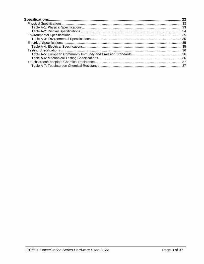
Table of Contents Table of Contents ........................................................................................................................... 2
Copyright and Trademark Notice .....................................................................................................................4 Product Warranty Information ..........................................................................................................................4 Technical Assistance .......................................................................................................................................4
Introduction .................................................................................................................................... 5 Model Number Configurations .........................................................................................................................6
Installation ...................................................................................................................................... 8 Selecting a Location .........................................................................................................................................8
Underwriters Laboratories UL508 Approval ........................................................................................8 Environmental Guidelines .......................................................................................................................8 Electrical Grounding Guidelines ............................................................................................................9 Temperature and Humidity Guidelines .................................................................................................9 Enclosure Guidelines ...............................................................................................................................9 UL Hazardous Location Class I, Division 2 Guidelines ................................................................. 10 Setting Up the PowerStat ion for Use in a Hazardous Environment .................................... 11
Preparing for Installation ............................................................................................................................... 12 Creating a Cutout .................................................................................................................................. 12
Installing the PowerStation ............................................................................................................................ 13 Mounting an IPC/IPX00 Remote PowerStation ............................................................................... 13 Mounting an IPC/IPX 10” PowerStation ............................................................................................ 14 Mounting an IPC/IPX 15” PowerStation ............................................................................................ 16 Mounting an IPC/IPX 17” PowerStation ............................................................................................ 18
Hardware Overview ...................................................................................................................... 20 PowerStation I/O ........................................................................................................................................... 20
Configuring the RS232/422/485 Serial Port ........................................................................................... 21 Using a IPC/IPX PowerStation with a Parker PHM Monitor.......................................................... 22
PowerStation AC Power Connections........................................................................................................... 23 AC Power Switch ................................................................................................................................... 24 Soft On/Off Power Button .................................................................................................................... 24
Maintenance ................................................................................................................................. 25 Internal Maintenance ..................................................................................................................................... 25
Electrostatic Discharge (ESD) Precautions ........................................................................................... 25 Opening the PowerStation....................................................................................................................... 26 Adding Expansion Cards......................................................................................................................... 27 Inserting the PCI Expansion Card ............................................................................................................. 28 Adding/Replacing the DRAM .................................................................................................................... 29
Touchscreen Maintenance ............................................................................................................................ 30 Calibrating the Touchscreen ..................................................................................................................... 30
PowerStation Utilities .................................................................................................................................... 31 Acronis Backup and Recovery Software ................................................................................................. 31 Intel Solid State Drive Toolbox Software .................................................................................................. 31 PowerSmart Software ............................................................................................................................. 32 \Parker Directory ....................................................................................................................................... 32 Utilities, Drivers & Documentation and CD ............................................................................................ 32
IPC/IPX PowerStation Series Hardware User Guide Page 3 of 37
Specifications............................................................................................................................... 33 Physical Specifications .................................................................................................................................. 33
Table A-1: Physical Specifications ............................................................................................................ 33 Table A-2: Display Specifications ............................................................................................................. 34
Environmental Specifications ........................................................................................................................ 35 Table A-3: Environmental Specifications .................................................................................................. 35
Electrical Specifications ................................................................................................................................ 35 Table A-4: Electrical Specifications ........................................................................................................... 35
Testing Specifications ................................................................................................................................... 36 Table A-5: European Community Immunity and Emission Standards ...................................................... 36 Table A-6: Mechanical Testing Specifications .......................................................................................... 36
Touchscreen/Faceplate Chemical Resistance .............................................................................................. 37 Table A-7: Touchscreen Chemical Resistance ......................................................................................... 37
IPC/IPX PowerStation Series Hardware User Guide Page 4 of 37
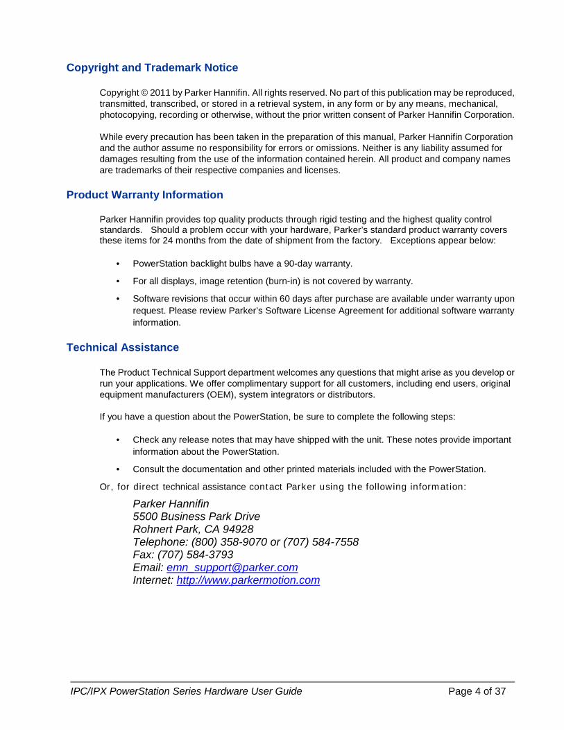
Copyright and Trademark Notice
Copyright © 2011 by Parker Hannifin. All rights reserved. No part of this publication may be reproduced, transmitted, transcribed, or stored in a retrieval system, in any form or by any means, mechanical, photocopying, recording or otherwise, without the prior written consent of Parker Hannifin Corporation.
While every precaution has been taken in the preparation of this manual, Parker Hannifin Corporation and the author assume no responsibility for errors or omissions. Neither is any liability assumed for damages resulting from the use of the information contained herein. All product and company names are trademarks of their respective companies and licenses.
Product Warranty Information
Parker Hannifin provides top quality products through rigid testing and the highest quality control standards. Should a problem occur with your hardware, Parker’s standard product warranty covers these items for 24 months from the date of shipment from the factory. Exceptions appear below:
• PowerStation backlight bulbs have a 90-day warranty.
• For all displays, image retention (burn-in) is not covered by warranty.
• Software revisions that occur within 60 days after purchase are available under warranty upon request. Please review Parker’s Software License Agreement for additional software warranty information.
Technical Assistance
The Product Technical Support department welcomes any questions that might arise as you develop or run your applications. We offer complimentary support for all customers, including end users, original equipment manufacturers (OEM), system integrators or distributors.
If you have a question about the PowerStation, be sure to complete the following steps:
• Check any release notes that may have shipped with the unit. These notes provide important information about the PowerStation.
• Consult the documentation and other printed materials included with the PowerStation.
Or, for direct technical assistance contact Parker using the following information:
Parker Hannifin 5500 Business Park Drive Rohnert Park, CA 94928 Telephone: (800) 358-9070 or (707) 584-7558 Fax: (707) 584-3793 Email: [email protected] Internet: http://www.parkermotion.com
IPC/IPX PowerStation Series Hardware User Guide Page 5 of 37
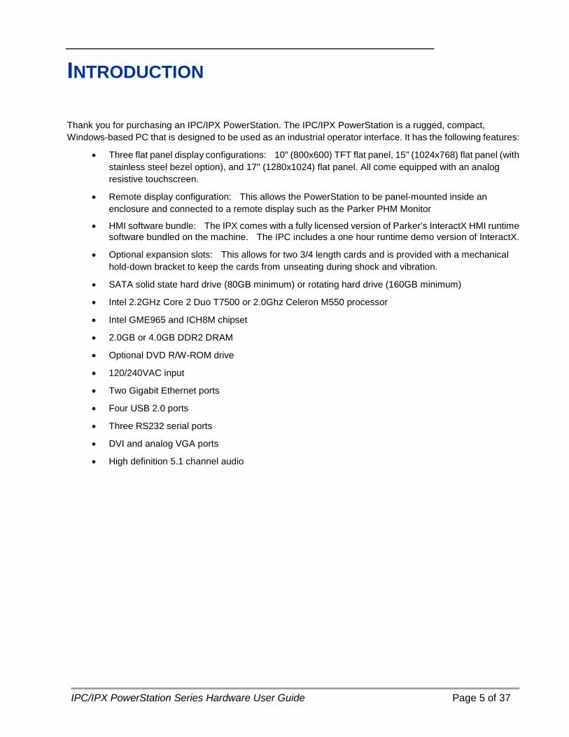
INTRODUCTION
Thank you for purchasing an IPC/IPX PowerStation. The IPC/IPX PowerStation is a rugged, compact, Windows-based PC that is designed to be used as an industrial operator interface. It has the following features:
• Three flat panel display configurations: 10" (800x600) TFT flat panel, 15" (1024x768) flat panel (with stainless steel bezel option), and 17" (1280x1024) flat panel. All come equipped with an analog resistive touchscreen.
• Remote display configuration: This allows the PowerStation to be panel-mounted inside an enclosure and connected to a remote display such as the Parker PHM Monitor
• HMI software bundle: The IPX comes with a fully licensed version of Parker’s InteractX HMI runtime software bundled on the machine. The IPC includes a one hour runtime demo version of InteractX.
• Optional expansion slots: This allows for two 3/4 length cards and is provided with a mechanical hold-down bracket to keep the cards from unseating during shock and vibration.
• SATA solid state hard drive (80GB minimum) or rotating hard drive (160GB minimum)
• Intel 2.2GHz Core 2 Duo T7500 or 2.0Ghz Celeron M550 processor
• Intel GME965 and ICH8M chipset
• 2.0GB or 4.0GB DDR2 DRAM
• Optional DVD R/W-ROM drive
• 120/240VAC input
• Two Gigabit Ethernet ports
• Four USB 2.0 ports
• Three RS232 serial ports
• DVI and analog VGA ports
• High definition 5.1 channel audio

IPC/IPX PowerStation Series Hardware User Guide Page 6 of 37
Model Number Configurations The model number configuration of the IPX/IPC PowerStation is a good overview of the options available to customers. The full model configurator is as follows:
IPX15T – 1 C – 7 4 S – D A 3
PowerStation Series IPX – IP Series with InteractX HMI Software IPC – IP Series with Windows Operating System only Display Size 00N – no display (headless) 10S – 10” display (600 x 800 resolution) 15T – 15” display (1024 x 768 resolution) 15A – 15” display (1024 x 768 resolution) Stainless Steel Bezel 17T – 17” display (1280 x 1024 resolution) Expansion Card BUS 1 – No Expansion 2 – PCI Expansion (2 Slots) Processor Option C – Celeron M550 (2.0GHz) D – Core2 Duo T7500 (2.2GHz) Operating System Option N – No Operating System 2 – Windows 2000 E – Windows XP Embedded X – Windows XP Pro 7 – Windows 7 Pro 32-bit H – Windows 7 Pro 64-bit DRAM Option 2 – 2GB DDR2 Memory 4 – 4GB DDR2 Memory System Storage Option N – No Storage H – Hard Drive S – Solid State Drive Optical Drive Option N – No Optical Drive D – DVD-RW Optical Drive Input Voltage A – AC Input Agency Approval Option 1 – No Agency Approvals 3 – UL/CUL/CE Approvals 4 – UL/CUL/CE/Class 1, Division 2 Approvals
IPC/IPX PowerStation Series Hardware User Guide Page 7 of 37
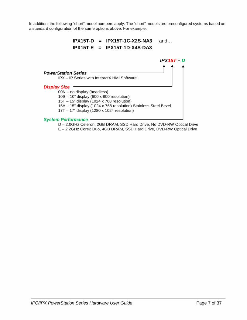
In addition, the following “short” model numbers apply. The “short” models are preconfigured systems based on a standard configuration of the same options above. For example:
IPX15T-D = IPX15T-1C-X2S-NA3 and… IPX15T-E = IPX15T-1D-X4S-DA3
IPX15T – D
PowerStation Series IPX – IP Series with InteractX HMI Software Display Size 00N – no display (headless) 10S – 10” display (600 x 800 resolution) 15T – 15” display (1024 x 768 resolution) 15A – 15” display (1024 x 768 resolution) Stainless Steel Bezel 17T – 17” display (1280 x 1024 resolution) System Performance D – 2.0GHz Celeron, 2GB DRAM, SSD Hard Drive, No DVD-RW Optical Drive E – 2.2GHz Core2 Duo, 4GB DRAM, SSD Hard Drive, DVD-RW Optical Drive
IPC/IPX PowerStation Series Hardware User Guide Page 8 of 37
INSTALLATION
Selecting a Location The first step when installing the PowerStation is to select an appropriate location. This is the most important aspect of the installation process because the location you select affects the unit’s performance, ease of use and life-expectancy. This section provides guidelines to follow when selecting a location. Underwriters Laboratories UL508 Approval In order to obtain Underwriters Laboratories (UL508) approval for your PowerStation installation, the installation must meet the following criteria:
• The PowerStation is suitable for mounting on the flat surface of a Type 4X Indoor Use Only or Type 12 enclosure.
• The equipment is to be provided with a branch circuit protection rated no greater than 20 A.
• The AC input to the IPC/IPX PowerStation is 100-240 Vac 50-60 Hz. A NEMA 5-15P power cord is included with each unit for 125 Vac operation. A NEMA 6-15P power cord is required for above 125 Vac.
Warning — A NEMA 6-15P power cord (not supplied with the IPC/IPX PowerStation) is required for operation greater than 125 Vac. The NEMA 6-15P power cord is used for 208 Vac and 240 Vac circuits and is rated to 250 Vac maximum.
Environmental Guidelines In general, select a location that limits the PowerStation’s exposure to adverse conditions such as dust, oil, moisture, condensation, and corrosive vapors.
The IPC/IPX PowerStation’s touchscreen/faceplate assembly is designed to meet the Type 4X Indoor Use Only or Type 12 rating. Mount the PowerStation in an enclosure that supports this rating if it is a requirement for the installation.
The touchscreen/faceplate is resistant to a variety of chemicals. Please refer to Table A-7 for a complete list.
IPC/IPX PowerStation Series Hardware User Guide Page 9 of 37
Electrical Grounding Guidelines To minimize unwanted electrical interference, select a location away from machinery that produces intense electrical noise (arc welders, for example). If you cannot avoid electrical noise, isolate input power to the unit and separate all data communication cables from AC power lines.
Important — Use the PowerStation ground stud to connect the unit to a suitable ground reference, such as earth ground or building steel. This ensures the unit is in compliance with immunity and emissions requirements necessary for proper operation.
Temperature and Humidity Guidelines You can safely operate the PowerStation within the temperature range of 0o to 50oC. Remember that the temperature within an enclosure is generally higher than the external temperature. If the PowerStation is operating inside an enclosure at temperature levels above its rated ambient temperature, you must cool the enclosure.
• Limit the PowerStation’s exposure to adverse conditions, such as dust, oil, moisture, and corrosive vapors in order to minimize maintenance and repair costs.
• Be sure to choose an area for the PowerStation that is free from moisture or condensing humidity.
Important — The DVD-RW optical drive is rated for 5-45C operation. The recording speed may be limited or reduced near or outside those operational limits due to the temperature sensitive nature of the device. Substantial shock and vibration may also impair reliable operation.
Enclosure Guidelines Select an enclosure that is large enough to allow free airflow in and around the PowerStation.
You should allow a minimum of 2 inches between the inside of the enclosure and the top, bottom, sides, and back of the PowerStation. Make sure that the surface of the enclosure on which the PowerStation is mounted is flat and free of raised or depressed areas.
Refer to Table A1 or the CD that came with your PowerStation for dimensional drawings.
Important — The IPC/IPX PowerStation’s touchscreen/faceplate assembly is designed to meet the Type 4X Indoor Use Only or Type 12 rating. Mount the PowerStation in an enclosure that supports this rating if it is a requirement for the installation.

IPC/IPX PowerStation Series Hardware User Guide Page 10 of 37
UL Hazardous Location Class I, Division 2 Guidelines If you purchased a UL Class I, Division 2 compliant PowerStation, you must comply to these statements in order to maintain a safe operating environment:
• This equipment is suitable for use in Class I, Division 2, Groups A, B, C and D or Non-Hazardous Locations Only. Temperature rating T5.
• The input and output (I/O) wiring must be in accordance with Class I, Division 2 wiring methods and in accordance with the authority having jurisdiction.
• Keyboard, Mouse, Microphone, USB Ports and Audio In/Out ports not utilized other than for initial setup and maintenance; evaluated and are non-latching nor non-incendive. Special warning required.
• Make sure that the PowerStation’s on/off switch is secured in the “ON” position using the supplied power switch and power cord bracket. An external disconnect device rated 240V and 4A must be installed outside the hazardous location area and there must be a marking near the unit that specifies the location of the disconnect device.
• When performing field wiring, always use copper wire with 60C or 60/75C insulation and a tightening torque of 7.0lbs/in (0.79 N-m).
Warning – Explosion Hazard • Substitution of components may impair suitability for Class I, Division 2. • Do not disconnect equipment unless power has been switched off or the
area is known to be non-hazardous.
IPC/IPX PowerStation Series Hardware User Guide Page 11 of 37
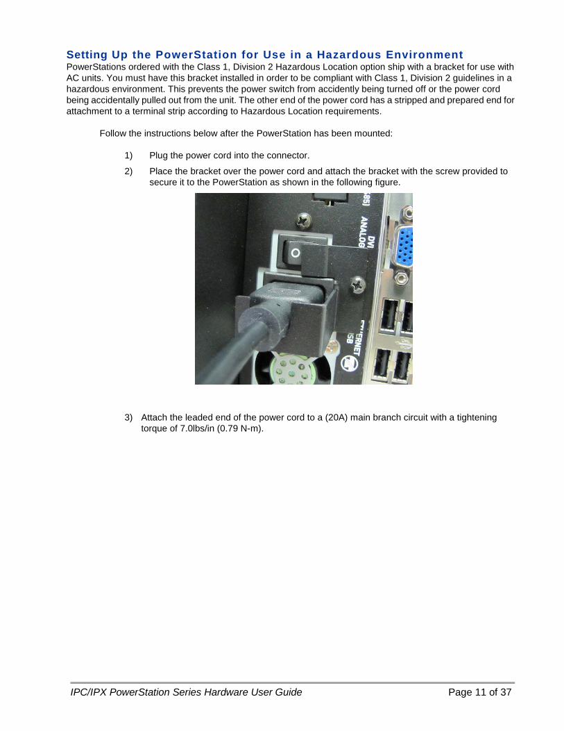
Setting Up the PowerStation for Use in a Hazardous Environment PowerStations ordered with the Class 1, Division 2 Hazardous Location option ship with a bracket for use with AC units. You must have this bracket installed in order to be compliant with Class 1, Division 2 guidelines in a hazardous environment. This prevents the power switch from accidently being turned off or the power cord being accidentally pulled out from the unit. The other end of the power cord has a stripped and prepared end for attachment to a terminal strip according to Hazardous Location requirements.
Follow the instructions below after the PowerStation has been mounted:
1) Plug the power cord into the connector.
2) Place the bracket over the power cord and attach the bracket with the screw provided to secure it to the PowerStation as shown in the following figure.
3) Attach the leaded end of the power cord to a (20A) main branch circuit with a tightening torque of 7.0lbs/in (0.79 N-m).
IPC/IPX PowerStation Series Hardware User Guide Page 12 of 37
Preparing for Installation Once you select a mounting location for the PowerStation you need to create a cutout for all models except the remote configuration, which uses four built-in flanges for direct attachment to a mounting surface.
Creating a Cutout Be sure to follow the cutout diagrams in the dimensional drawings precisely. This ensures that the PowerStation is properly sealed in its enclosure. You can find the dimensional drawings on the PowerStation CD shipped with your unit.
1) To ensure a proper mounting seal, maintain proper surface flatness and edge quality.
The cutout dimensions for the IPC/IPX PowerStation are shown in the following table:
IPC/IPX Model Cutout Height Cutout Width
00N n/a n/a
10S 9.95" 12.6"
15T 12.4" 15.9"
17T 14.26" 17.06"
2) Debur the edges of the cutout area, removing dirt and debris that might come in contact with the unit.
IPC/IPX PowerStation Series Hardware User Guide Page 13 of 37
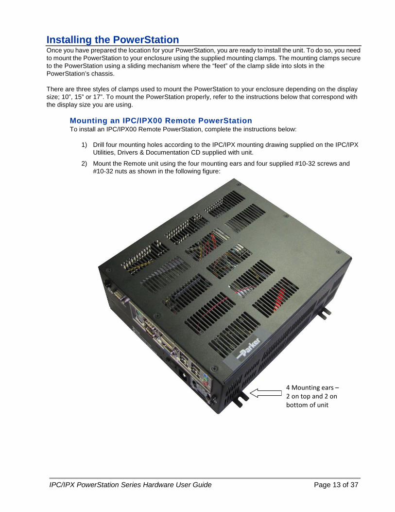
Installing the PowerStation Once you have prepared the location for your PowerStation, you are ready to install the unit. To do so, you need to mount the PowerStation to your enclosure using the supplied mounting clamps. The mounting clamps secure to the PowerStation using a sliding mechanism where the “feet” of the clamp slide into slots in the PowerStation’s chassis.
There are three styles of clamps used to mount the PowerStation to your enclosure depending on the display size; 10”, 15” or 17”. To mount the PowerStation properly, refer to the instructions below that correspond with the display size you are using.
Mounting an IPC/IPX00 Remote PowerStation To install an IPC/IPX00 Remote PowerStation, complete the instructions below:
1) Drill four mounting holes according to the IPC/IPX mounting drawing supplied on the IPC/IPX Utilities, Drivers & Documentation CD supplied with unit.
2) Mount the Remote unit using the four mounting ears and four supplied #10-32 screws and #10-32 nuts as shown in the following figure:
4 Mounting ears – 2 on top and 2 on bottom of unit
IPC/IPX PowerStation Series Hardware User Guide Page 14 of 37
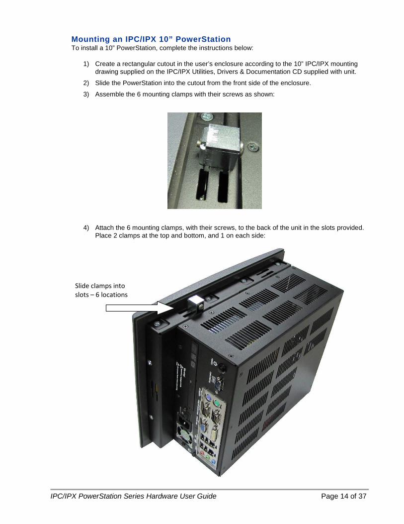
Mounting an IPC/IPX 10” PowerStation To install a 10” PowerStation, complete the instructions below:
1) Create a rectangular cutout in the user’s enclosure according to the 10” IPC/IPX mounting drawing supplied on the IPC/IPX Utilities, Drivers & Documentation CD supplied with unit.
2) Slide the PowerStation into the cutout from the front side of the enclosure.
3) Assemble the 6 mounting clamps with their screws as shown:
4) Attach the 6 mounting clamps, with their screws, to the back of the unit in the slots provided. Place 2 clamps at the top and bottom, and 1 on each side:
Slide clamps into slots – 6 locations
IPC/IPX PowerStation Series Hardware User Guide Page 15 of 37
5) Insert the clamp into the wide end of the slot and slide it to the thin end.
6) Tighten each of the mounting screws against the front of the enclosure.
7) Torque the screws until the gasket is compressed by 50%.
Caution — Do not over-tighten the screw/clamp assembly or you may damage the PowerStation. However, under-tightening may not guarantee a Type 4X Indoor Use Only or Type 12 rating.
8) Tighten the screws in a crosswise sequence to ensure a good seal and prevent damage.
Note that properly tightening the clamps may not result in a gasket seal that is totally depressed by the bezel and flush with the enclosure. Since a proper Type 4X Indoor Use Only or Type 12 rating requires a 50% compression of the gasket, you may see a small gap between the bezel and the enclosure.

IPC/IPX PowerStation Series Hardware User Guide Page 16 of 37
Mounting an IPC/IPX 15” PowerStation To install a 15” PowerStation, complete the instructions below:
1) Create a rectangular cutout in the user’s enclosure according to the 15” IPC/IPX mounting drawing supplied on the IPC/IPX Utilities, Drivers & Documentation CD supplied with unit.
2) Slide the PowerStation into the cutout from the front side of the enclosure.
3) Assemble the 8 mounting clamps with their screws and locking nuts as shown (do not tighten the locking nut until Step 6:
4) Insert the clamp into the wide end of the slot and slide it to the thin end as shown in the following figure:
Slide clamps into slots – 8 locations
Locking Nut Location
IPC/IPX PowerStation Series Hardware User Guide Page 17 of 37
5) Tighten each of the mounting screws against the front of the enclosure.
6) Torque the screws to 7 in/lbs in a crosswise sequence to ensure a good seal and prevent damage.
Caution — Do not over-tighten the screw/clamp assembly or you may damage the PowerStation. However, under-tightening may not guarantee a Type 4X Indoor Use Only or Type 12 rating.
7) Adjust the locking nut so that it is firmly against the surface of the clamp to prevent
loosening.
Note that properly tightening the clamps may not result in a gasket seal that is totally depressed by the bezel and flush with the enclosure. Since a proper NEMA 4/4x seal requires a 50% compression of the gasket, you may see a small gap between the bezel and the enclosure.
IPC/IPX PowerStation Series Hardware User Guide Page 18 of 37
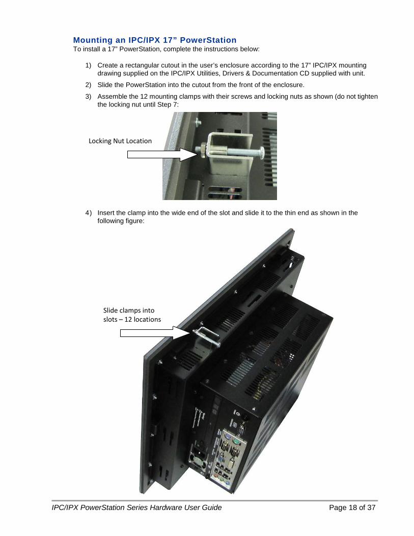
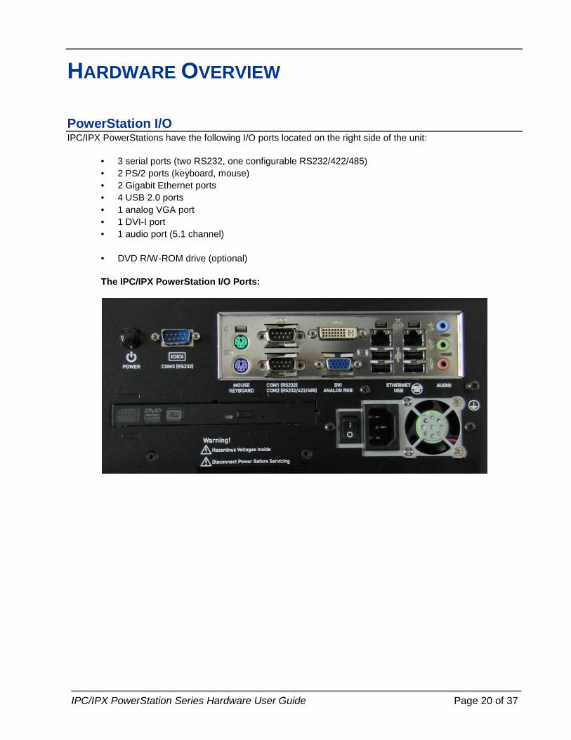
Mounting an IPC/IPX 17” PowerStation To install a 17” PowerStation, complete the instructions below:
1) Create a rectangular cutout in the user’s enclosure according to the 17” IPC/IPX mounting drawing supplied on the IPC/IPX Utilities, Drivers & Documentation CD supplied with unit.
2) Slide the PowerStation into the cutout from the front of the enclosure.
3) Assemble the 12 mounting clamps with their screws and locking nuts as shown (do not tighten the locking nut until Step 7:
4) Insert the clamp into the wide end of the slot and slide it to the thin end as shown in the following figure:
Slide clamps into slots – 12 locations
Locking Nut Location

IPC/IPX PowerStation Series Hardware User Guide Page 19 of 37
5) Tighten each of the mounting screws against the front of the enclosure.
6) Torque the screws to 7 in/lbs a crosswise sequence to ensure a good seal and prevent damage.
Caution — Do not over-tighten the screw/clamp assembly or you may damage the PowerStation. However, under-tightening may not guarantee a Type 4X Indoor Use Only or Type 12 rating.
7) Adjust the locking nut so that it is firmly against the surface of the clamp to prevent loosening.
Note that properly tightening the clamps may not result in a gasket seal that is totally depressed by the bezel and flush with the enclosure. Since a proper NEMA 4/4x seal requires a 50% compression of the gasket, you may see a small gap between the bezel and the enclosure.
IPC/IPX PowerStation Series Hardware User Guide Page 20 of 37
HARDWARE OVERVIEW
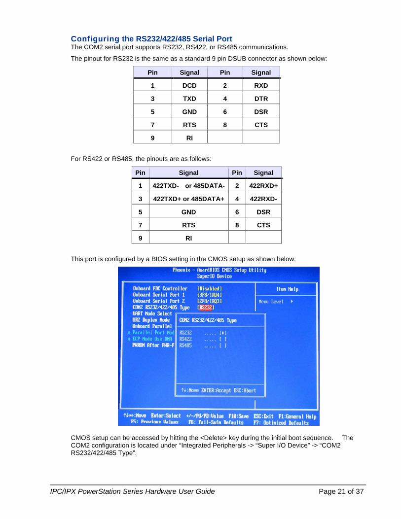
PowerStation I/O IPC/IPX PowerStations have the following I/O ports located on the right side of the unit:
• 3 serial ports (two RS232, one configurable RS232/422/485) • 2 PS/2 ports (keyboard, mouse) • 2 Gigabit Ethernet ports • 4 USB 2.0 ports • 1 analog VGA port • 1 DVI-I port • 1 audio port (5.1 channel)
• DVD R/W-ROM drive (optional)
The IPC/IPX PowerStation I/O Ports:
IPC/IPX PowerStation Series Hardware User Guide Page 21 of 37
Configuring the RS232/422/485 Serial Port The COM2 serial port supports RS232, RS422, or RS485 communications.
The pinout for RS232 is the same as a standard 9 pin DSUB connector as shown below:
Pin Signal Pin Signal
1 DCD 2 RXD
3 TXD 4 DTR
5 GND 6 DSR
7 RTS 8 CTS
9 RI
For RS422 or RS485, the pinouts are as follows:
Pin Signal Pin Signal
1 422TXD- or 485DATA- 2 422RXD+
3 422TXD+ or 485DATA+ 4 422RXD-
5 GND 6 DSR
7 RTS 8 CTS
9 RI
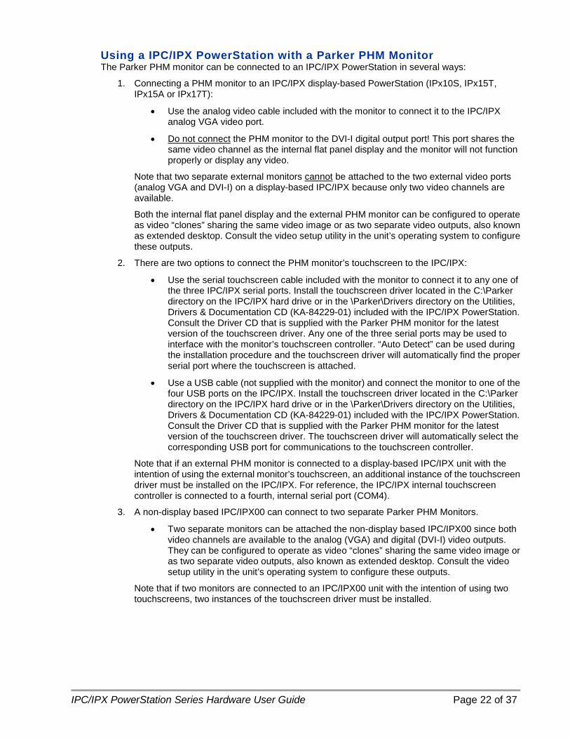
This port is configured by a BIOS setting in the CMOS setup as shown below:
CMOS setup can be accessed by hitting the <Delete> key during the initial boot sequence. The COM2 configuration is located under “Integrated Peripherals -> “Super I/O Device” -> “COM2 RS232/422/485 Type”.
IPC/IPX PowerStation Series Hardware User Guide Page 22 of 37
Using a IPC/IPX PowerStation with a Parker PHM Monitor The Parker PHM monitor can be connected to an IPC/IPX PowerStation in several ways:
1. Connecting a PHM monitor to an IPC/IPX display-based PowerStation (IPx10S, IPx15T, IPx15A or IPx17T):
• Use the analog video cable included with the monitor to connect it to the IPC/IPX analog VGA video port.
• Do not connect
Note that two separate external monitors
the PHM monitor to the DVI-I digital output port! This port shares the same video channel as the internal flat panel display and the monitor will not function properly or display any video.
cannot
Both the internal flat panel display and the external PHM monitor can be configured to operate as video “clones” sharing the same video image or as two separate video outputs, also known as extended desktop. Consult the video setup utility in the unit’s operating system to configure these outputs.
be attached to the two external video ports (analog VGA and DVI-I) on a display-based IPC/IPX because only two video channels are available.
2. There are two options to connect the PHM monitor’s touchscreen to the IPC/IPX:
• Use the serial touchscreen cable included with the monitor to connect it to any one of the three IPC/IPX serial ports. Install the touchscreen driver located in the C:\Parker directory on the IPC/IPX hard drive or in the \Parker\Drivers directory on the Utilities, Drivers & Documentation CD (KA-84229-01) included with the IPC/IPX PowerStation. Consult the Driver CD that is supplied with the Parker PHM monitor for the latest version of the touchscreen driver. Any one of the three serial ports may be used to interface with the monitor’s touchscreen controller. “Auto Detect” can be used during the installation procedure and the touchscreen driver will automatically find the proper serial port where the touchscreen is attached.
• Use a USB cable (not supplied with the monitor) and connect the monitor to one of the four USB ports on the IPC/IPX. Install the touchscreen driver located in the C:\Parker directory on the IPC/IPX hard drive or in the \Parker\Drivers directory on the Utilities, Drivers & Documentation CD (KA-84229-01) included with the IPC/IPX PowerStation. Consult the Driver CD that is supplied with the Parker PHM monitor for the latest version of the touchscreen driver. The touchscreen driver will automatically select the corresponding USB port for communications to the touchscreen controller.
Note that if an external PHM monitor is connected to a display-based IPC/IPX unit with the intention of using the external monitor’s touchscreen, an additional instance of the touchscreen driver must be installed on the IPC/IPX. For reference, the IPC/IPX internal touchscreen controller is connected to a fourth, internal serial port (COM4).
3. A non-display based IPC/IPX00 can connect to two separate Parker PHM Monitors.
• Two separate monitors can be attached the non-display based IPC/IPX00 since both video channels are available to the analog (VGA) and digital (DVI-I) video outputs. They can be configured to operate as video “clones” sharing the same video image or as two separate video outputs, also known as extended desktop. Consult the video setup utility in the unit’s operating system to configure these outputs.
Note that if two monitors are connected to an IPC/IPX00 unit with the intention of using two touchscreens, two instances of the touchscreen driver must be installed.

IPC/IPX PowerStation Series Hardware User Guide Page 23 of 37
PowerStation AC Power Connections All power connections, switches, and buttons are located on the right side of the unit.
Caution • The main power supply has internal protection, but no serviceable fuse. • The AC input to the IPC/IPX PowerStation is 100-240 Vac 50-60 Hz. A
NEMA 5-15P power cord is included with each unit for 125 Vac operation.
• A NEMA 6-15P power cord (not supplied with the IPC/IPX PowerStation) is required for operation greater than 125 Vac. The NEMA 6-15P power cord is used for 208 Vac and 240 Vac circuits and is rated to 250 Vac maximum.
• Proper installation of the PowerStation for use in European Union countries requires the use of a harmonized power cord. (The power cord must be identified with the <HAR> symbol.) Make sure that the PowerStation is only connected to the main supply with a harmonized power cord.

IPC/IPX PowerStation Series Hardware User Guide Page 24 of 37
AC Power Switch This switch turns power On/Off to the main power supply. When this switch is cycled Off and then On, the PowerStation will initiate its normal boot sequence. It has the same effect as removing and restoring power at the AC service panel. This behavior is controlled in the BIOS by the CMOS setup parameter “Power On After Power Fail” where the default setting is “ON” as shown below:
CMOS setup can be accessed by hitting the <Delete> key during the initial boot sequence. The Power On After Power Fail setting is located under “Integrated Peripherals -> “Super I/O Device” -> “PWRON After PWR-Fail”.
For information on using the power switch in a hazardous environment, refer to Setting Up the PowerStation for Use in a Hazardous Environment on page 11.
Soft On/Off Power Button This button can be used to boot the PowerStation from standby or after a Windows shutdown in situations where AC power is still present and the AC power switch has been left in the On position. It functions identically to the power button found on the front of most desktop PCs.

IPC/IPX PowerStation Series Hardware User Guide Page 25 of 37
MAINTENANCE
Internal Maintenance Before doing any internal maintenance, be sure to read and understand the procedures in this section to prevent injury to yourself and/or damage to the PowerStation.
Electrostatic Discharge (ESD) Precautions The PowerStation contains components that are extremely sensitive to electrostatic discharges (ESD). Before you open the system, be sure to follow these simple precautions to protect the PowerStation from ESD damage.
• Always turn off power to the PowerStation before opening. Do not touch any internal components while the system is on.
• Disconnect power before performing any internal maintenance or troubleshooting.
• Only handle PowerStation internal components in an ESD-safe location, using appropriate grounding methods.
• Wear a grounding wrist strap for continuous protection.
• Be particularly careful not to touch the components on the printed circuit boards.
• Keep any PowerStation component in its anti-static packaging when it is not installed in the unit.

IPC/IPX PowerStation Series Hardware User Guide Page 26 of 37
Opening the PowerStation In order to perform internal maintenance, you have to open the back cover of the unit. Be sure to follow the ESD guidelines discussed previously.
Caution — For safety reasons, the PowerStation should be opened only by qualified service personnel.
1) Remove the screws on the PowerStation as shown below. There are 15 total screws; 7 on the top, 6 on the back and 2 on the bottom. If the PowerStation has the PCI Expansion card option installed, there will be only 13 screws; 7 on the top and 6 on the back.
2) Lift the back cover off of the PowerStation.
3) From here you can add an expansion card or add/replace DRAM as necessary, refer to the following Adding Expansion Cards, and Adding/Replacing DRAM.
Screws may be located on the Top, Back & Bottom

IPC/IPX PowerStation Series Hardware User Guide Page 27 of 37
Adding Expansion Cards The IPC/IPX Expansion Option supports two 3/4 length (10.25” maximum length) PCI cards. Refer to the following figure:
Note • The PCI riser card supports either 5V or universal-type PCI expansion
cards. They do not support 3.3V cards. • The maximum length for expansion cards in the 3/4 length PCI
Expansion option backshell is approximately 10.25 inches (260mm).
Optional PCI Expansion Option
IPC/IPX PowerStation Series Hardware User Guide Page 28 of 37
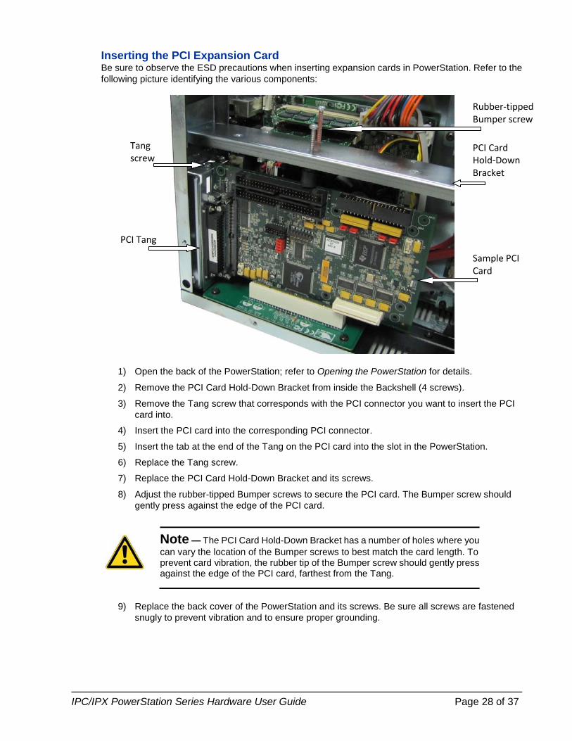
Inserting the PCI Expansion Card Be sure to observe the ESD precautions when inserting expansion cards in PowerStation. Refer to the following picture identifying the various components:
1) Open the back of the PowerStation; refer to Opening the PowerStation for details.
2) Remove the PCI Card Hold-Down Bracket from inside the Backshell (4 screws).
3) Remove the Tang screw that corresponds with the PCI connector you want to insert the PCI card into.
4) Insert the PCI card into the corresponding PCI connector.
5) Insert the tab at the end of the Tang on the PCI card into the slot in the PowerStation.
6) Replace the Tang screw.
7) Replace the PCI Card Hold-Down Bracket and its screws.
8) Adjust the rubber-tipped Bumper screws to secure the PCI card. The Bumper screw should gently press against the edge of the PCI card.
Note — The PCI Card Hold-Down Bracket has a number of holes where you can vary the location of the Bumper screws to best match the card length. To prevent card vibration, the rubber tip of the Bumper screw should gently press against the edge of the PCI card, farthest from the Tang.
9) Replace the back cover of the PowerStation and its screws. Be sure all screws are fastened
snugly to prevent vibration and to ensure proper grounding.
PCI Card Hold-Down Bracket
Sample PCI Card
Tang screw
PCI Tang
Rubber-tipped Bumper screw

IPC/IPX PowerStation Series Hardware User Guide Page 29 of 37
Adding/Replacing the DRAM Be sure to observe the ESD precautions before opening the back of the PowerStation.
Note — The DRAM module must be a 200-pin DDRII 533/667Mhz SODIMM (PC2-4200 or PC2-5300) up to 2GB for each socket.
1) Open the back of the PowerStation; refer to Opening the PowerStation for details.
2) Locate the DRAM sockets near the CPU fan as shown below:
3) Push the ears out that hold the DRAM in place and carefully lift the DRAM up and out.
4) Insert the new DRAM in the correct position, so that the off-center notch matches with the connector on the board.
Note — DRAM can be installed in either (or both) slots. You can mix and match the sizes of the DRAM modules as well.
5) Push the top edge of the DRAM down tightly against the board. The ears will retract completely
into position when properly installed.
6) Snap the ears into position to lock the DRAM into place.
7) Replace the back cover of the PowerStation and its screws. Be sure all screws are fastened snugly to prevent vibration and to ensure proper grounding.
Two DRAM modules (shown populated)
IPC/IPX PowerStation Series Hardware User Guide Page 30 of 37
Touchscreen Maintenance Cleaning the Touchscreen Occasionally, you may need to clean the PowerStation screen. Clean the screen using warm, soapy water and a cloth. You can also use any non-abrasive cleaner. See Touchscreen Chemical Resistance Table A7, for a list of substances the screen can resist with no visible effect.
Do not use any harsh material or powder, such as steel wool or abrasive cleansers, to clean the screen surface. The surface is sensitive to scraping, sharp blows, or punctures. Therefore, keep screwdrivers or other sharp objects away from the screen surface.
Caution — Do not clean the unit while it is running. Turn off the unit before cleaning it in order to avoid inadvertently activating the touchscreen.
Calibrating the Touchscreen Calibrating the touchscreen ensures that it is aligned with your display. The PowerStation’s touchscreen is calibrated before leaving Parker manufacturing. However, you may need to recalibrate the touchscreen after a period of time, if you are using a remote, stand-alone configuration, or whenever the cursor does not follow the touches on the screen.
This section explains how to calibrate the Hampshire touchscreen driver under Windows XP Professional.
To calibrate the touchscreen driver, complete the following steps:
1) Select Start, Programs, Hampshire TSHARC Control Panel or the Touchscreen Control Panel icon in the System Tray. The control panel appears.
2) Follow the on screen instructions for selecting which monitor to calibrate.
3) Select the Calibration tab.
4) With your finger, touch the center of where the arrows are pointing. The Calibration screen appears.
5) Touch the target where it appears on the screen, hold your finger there until prompted to release. The screen guides you through the Touch - Hold - Release process.
6) Repeat the process three more times in the other three corners of the screen. A test screen appears.
7) Move your finger across the monitor. The target should move with your finger. If so, the calibration was successful.
8) Select Accept. 9) On the control panel, select Apply and then select OK.
IPC/IPX PowerStation Series Hardware User Guide Page 31 of 37
PowerStation Utilities Acronis Backup and Recovery Software The IPC/IPX PowerStation comes with Acronis True Image OEM backup and recovery software preinstalled. This software allows for the backup and restoration of selected files and folders or entire disks and partitions.
Acronis also provides a Recovery Manager that allows the original factory image to be restored in the event that the Operating System is unable to boot properly. This can be invoked after a reboot by pressing F11 when the option to start the Acronis OEM Zone software is displayed right after the BIOS splash screen.
For further information regarding Acronis backup and recovery software, its features and use, please refer to the Help documentation provided in the Acronis True Image OEM software installed on the IPC/IPX.
It is recommended that once the IPC/IPX has been configured with the proper software drivers, applications and/or InteractX HMI projects, an Acronis hard drive backup image be created and saved to a DVD-RW disk, USB drive, external hard drive or Acronis OEM Zone.
Notice: “Acronis”, "Acronis Compute with Confidence", “Acronis Snap Restore”, “Acronis Recovery Manager, “Acronis OEM Zone” and the Acronis logo are trademarks of Acronis, Inc.
Intel Solid State Drive Toolbox Software The IPC/IPX PowerStation comes with the Intel SSD Toolbox software preinstalled. This set of utilities provides the management tools necessary to optimize Intel Solid State Drives for peak performance. Optimization is achieved by using Trim functionality to remove data files that have been marked for deletion but not physically erased by the Operating System. This way the SSD no longer has to manage these files.
It is recommended to run the optimizer on a regular basis to maintain out-of-box performance. The Toolbox provides a scheduler that allows the optimizer to run automatically each day without user intervention.
IPC/IPX PowerStation Series Hardware User Guide Page 32 of 37
PowerSmart Software The IPC/IPX PowerStation also contains the PowerSmart software. This software allows you to keep track of various system parameters, such as:
• Minimum, maximum, and current CPU temperature
• Minimum, maximum, and current internal ambient temperature
• CPU fan speed
• Total number of power cycles
• Total number of hours of operation
Use the PowerSmart icon in the \Parker\Powersmart directory to display these parameters in real time. The PowerSmart window also has a temperature trend graph for CPU and ambient temperatures, as well as an indicator that lets you know if the monitoring microcontroller is working properly.
\Parker Directory The installation files for all IPX/IPC PowerStation drivers can be found in the \Parker directory. This directory also contains the PowerSmart application and the Intel SSD Toolbox.
Utilities, Drivers & Documentation and CD The IPC/IPX PowerStation is shipped with a Utilities, Drivers & Documentation CD (KA-84229-01). This CD contains all of the dimensional drawings, software, drivers and documentation needed for the IPC/IPX PowerStation.
If any of the software on your system becomes lost or corrupted, you can reinstall it from this CD.

IPC/IPX PowerStation Series Hardware User Guide Page 33 of 37
SPECIFICATIONS
Physical Specifications Table A-1: Physical Specifications
Category Specifications Operating System • Microsoft XP Professional
BIOS • Award BIOS
CPU/Chipset • Intel 2.2GHz Core 2 Duo T7500 or 2.0Ghz Celeron M550 processor
• Intel GME965 + ICH8M chipset
Memory • 200 pin SODIMM DDRII 533/667Mhz DRAM sockets x 2 • Supports PC2-4200 or PC2-5300 memory modules • 4GB maximum memory
I/O Ports • Gigabit Ethernet x 2 • RS232 serial x 3 • USB 2.0 x 4 • DVI-I • Analog VGA • PS/2 keyboard • PS/2 mouse
Audio • Intel HD 5.1 channel
Storage • SATA solid state drive (80GB minimum) or rotating hard drive (160GB minimum)
• Optional slim mobile DVD R/W-ROM drive
Touchscreen • Analog Resistive
Expansion Slots • Optional 3/4 length PCI slots x 2 • A mechanical hold-down is provided to keep the cards from unseating
due to shock and vibration
Dimensions (H x W x D) of base configuration
• 10” PowerStation — 11.0” x 13.8” x 6.2” (279mm x 351mm x 157mm) • 15” PowerStation — 13.3” x 16.8” x 6.75” (338mm x 427mm x 171mm) • 17” PowerStation — 15.7” x 18.0” x 6.47” (399mm x 457mm x 164mm) • Remote PowerStation — 10.9” x 11.3” x 4.3” (277mm x 287mm x
109mm) NOTE: The optional PCI Expansion chassis adds 2.2” (56mm) to the overall unit depth.
Weight • 10” PowerStation — 16.7 lbs. (7.6Kg) • 15” PowerStation — 18.9 lbs. (8.6Kg) • 17” PowerStation — 20.9 lbs. (9.5Kg) • Remote PowerStation — 11.3 lbs. (5.1Kg) NOTE: The optional PCI Expansion chassis adds 1.9 lbs. (0.9Kg) to the overall unit weight.
IPC/IPX PowerStation Series Hardware User Guide Page 34 of 37
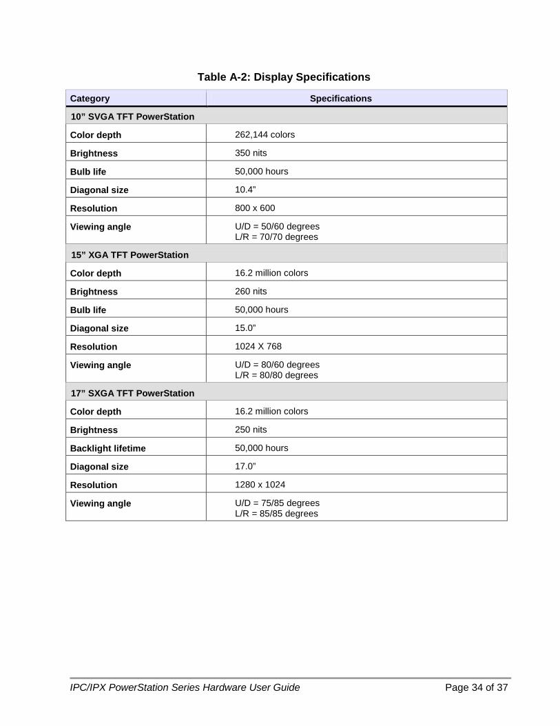
Table A-2: Display Specifications
Category Specifications
10” SVGA TFT PowerStation
Color depth 262,144 colors
Brightness 350 nits
Bulb life 50,000 hours
Diagonal size 10.4”
Resolution 800 x 600
Viewing angle U/D = 50/60 degrees L/R = 70/70 degrees
15” XGA TFT PowerStation
Color depth 16.2 million colors
Brightness 260 nits
Bulb life 50,000 hours
Diagonal size 15.0”
Resolution 1024 X 768
Viewing angle U/D = 80/60 degrees L/R = 80/80 degrees
17” SXGA TFT PowerStation
Color depth 16.2 million colors
Brightness 250 nits
Backlight lifetime 50,000 hours
Diagonal size 17.0”
Resolution 1280 x 1024
Viewing angle U/D = 75/85 degrees L/R = 85/85 degrees
IPC/IPX PowerStation Series Hardware User Guide Page 35 of 37
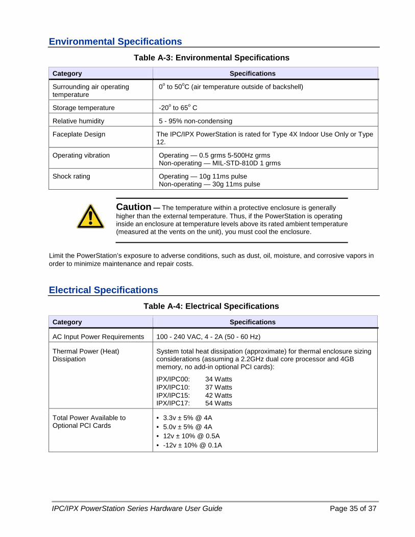
Environmental Specifications Table A-3: Environmental Specifications
Category Specifications
Surrounding air operating temperature
0o to 50oC (air temperature outside of backshell)
Storage temperature -20o to 65o C
Relative humidity 5 - 95% non-condensing
Faceplate Design The IPC/IPX PowerStation is rated for Type 4X Indoor Use Only or Type 12.
Operating vibration Operating — 0.5 grms 5-500Hz grms Non-operating — MIL-STD-810D 1 grms
Shock rating Operating — 10g 11ms pulse Non-operating — 30g 11ms pulse
Caution — The temperature within a protective enclosure is generally higher than the external temperature. Thus, if the PowerStation is operating inside an enclosure at temperature levels above its rated ambient temperature (measured at the vents on the unit), you must cool the enclosure.
Limit the PowerStation’s exposure to adverse conditions, such as dust, oil, moisture, and corrosive vapors in order to minimize maintenance and repair costs. Electrical Specifications
Table A-4: Electrical Specifications
Category Specifications
AC Input Power Requirements 100 - 240 VAC, 4 - 2A (50 - 60 Hz)
Thermal Power (Heat) Dissipation
System total heat dissipation (approximate) for thermal enclosure sizing considerations (assuming a 2.2GHz dual core processor and 4GB memory, no add-in optional PCI cards):
IPX/IPC00: 34 Watts IPX/IPC10: 37 Watts IPX/IPC15: 42 Watts IPX/IPC17: 54 Watts
Total Power Available to Optional PCI Cards
• 3.3v ± 5% @ 4A • 5.0v ± 5% @ 4A • 12v ± 10% @ 0.5A • -12v ± 10% @ 0.1A

IPC/IPX PowerStation Series Hardware User Guide Page 36 of 37
Testing Specifications
Table A-5: European Community Immunity and Emission Standards
Test Specification
EMC Testing, Emissions • EC Generic EN61000-6-4 (2007) / EN55011+A1 (2010)
EMC Testing, Immunity • EC Generic EN 61000-6-2 (2005) • EN 61000-3-2 (2006) Harmonic Current Emissions • EN 61000-3-3 (1995+A1:2001+A2:2005) Voltage Fluctuations and
Flicker • EN 61000-4-2 Electrostatic Discharge • EN 61000-4-3 Radiated Immunity • EN 61000-4-4 Fast Transient/Burst Susceptibility • EN 61000-4-5 Surge Immunity • EN 61000-4-6 Radio-Frequency Common Mode Immunity • EN 61000-4-8 Power-Frequency Magnetic Field Immunity • EN 61000-4-11 Voltage Dip Interrupt Immunity
Safety • EN60950-1:2006+A11:2009
Regulatory Agencies • UL 508 Ordinary Location • ISA 1212 Hazardous Location • CE • RoHS
Table A-6: Mechanical Testing Specifications
Test Specification
Operating vibration • Operating: 0.5 grms/MIL-STD-810F 514.3 • Non-operating: 1.0 grms/MIL-STD-810F 514.3
Mechanical shock • Operating — 10g 11ms pulse IEC-68-2-27/MIL-STD-810F 514.3 • Non-operating — 30g 11ms pulse IEC-68-2-27/MIL-STD-810F 514.3

IPC/IPX PowerStation Series Hardware User Guide Page 37 of 37
Touchscreen/Faceplate Chemical Resistance The PowerStation’s touchscreen is designed to meet the NEMA 4 rating. Mount the PowerStation in an enclosure that supports this rating in order to provide further protection. The PowerStation’s touchscreen is resistant to a variety of chemicals listed below with no visible effect.
Table A-7: Touchscreen Chemical Resistance Faceplate Chemical Resistance
Acetone Sulfuric Acid 10% Motor oil
MEK Hydrochloric Acid 10% Gasoline
Toluene Acetic Acid 10% Machine oil
Methylene Chloride Phosphoric Acid Salad oil
Isopropyl Alcohol
Sodium Hydroxide 10% Silicone
Xylene Carbon Tetrachloride Silicone grease G31
Hexane Potassium Hydroxide Kerosene
Butyl Cellosolve Ammonia Water 10% Gas oil
Cyclohexanone Sodium Chloride 26% Silicone oil
Trichloroethylene Zinc Chloride 81% Engine oil
Ethanol Cottonseed Oil Cleanser
Methanol Glycerin Nitric Acid 10%
Grease
All exposed PowerStation surfaces are resistive to the following chemicals:
• Commercial glass cleaners • Ammonia (10% dilute solution)
• Motor oil • Hydraulic fluid
• Diesel fuel • Gasoline (leaded and unleaded)
• Silicone-based lubricant • Alcohol (ethyl, methyl)
• Automatic transmission fluid •
Important — Sustained exposure to brake fluid or Gunk® brand degreaser can cause damage to the monitor materials.


