32
IRSE NEWS ISSUE 197 FEBRUARY 2014
IRSE NEWS ISSUE 197 FEBRUARY 2014

Front Cover: Picture of a BNSF Automatic Signal 8902 showing the ATP system with its inductive trip stop. This was taken at Belen, New Mexico, USA on the 25/02/2009. New CTC colour light signals have replaced the semaphores on this section of track, but there are still a few semaphores in service on this line. Photo: David F. Thurston, Ph.D., P.E. FIRSE
The IRSE Council taken on 19 April 2013 - see article on page 21

NO
T FO
R RE
-PRI
NTI
NG
©
IRSE NEWS | ISSUE 197 | FEBRUARY 2014
IRSE NEWS is published monthly by the Institution of Railway Signal Engineers (IRSE). The IRSE is not as a body responsible for the opinions expressed in IRSE NEWS.
© Copyright 2014, IRSE. All rights reserved. No part of this publication may be reproduced, stored in a retrieval system, or transmitted in any form or by any means without the permission in writing of the publisher. Copying of articles is not permitted except for personal and internal use. Multiple copying of the content of this publication without permission is always illegal.
Editor Ian J Allison 102 Beacon Road, Loughborough, LE11 2BH, UK Tel: +44 (0) 7794 879286 e-mail: [email protected]
Deputy Editor Tony Rowbotham 36 Burston Drive, Park Street, St Albans, AL2 2HP, UK e-mail: [email protected]
Assistant Editors Harry Ostrofsky (Africa) e-mail: [email protected] Tony Howker (Australasia) e-mail: [email protected] David Thurston (N. America) e-mail: [email protected] Buddhadev Dutta Chowdhury (Asia) e-mail: [email protected] Wim Coenraad (Europe) e-mail: [email protected] Priyank Patel (Younger Members) e-mail: [email protected]
Contributions Articles of a newsworthy or technical nature are always welcome for IRSE NEWS. Members should forward their contributions to one of the Editors listed above.
Advertising For advertising rates and deadlines call Andrew Walker at DVV Media Tel: +44 (0)208 652 5214 e-mail: [email protected]
Advertisements are accepted on the basis that the advertiser and agency (if any) warrant that the contents are true and correct in all respects.
Web Site For up to date information about the Institution or its activities, or to download a membership application form, log on to the IRSE Web Site: www.irse.org
London Office IRSE, 4th Floor, 1 Birdcage Walk, Westminster, London, SW1H 9JJ, United Kingdom
Enquiries
MEMBERSHIP OR OF A GENERAL NATURE Tel: +44 (0)20 7808 1180 Fax: +44 (0)20 7808 1196 e-mail: [email protected]
PROFESSIONAL DEVELOPMENT Tel: +44 (0)20 7808 1186 e-mail: [email protected]
LICENSING Tel: +44 (0)20 7808 1190 e-mail: [email protected]
1
www.facebook.com/IRSEUK www.facebook.com/IRSEOz www.facebook.com/ian.allison
IN THIS ISSUE Page Continuous Performance Improvement: Third Line Investigation and Support 2 (London January Paper) Andrew Cross
Life Cycle of a MRTS Project– Planning, Construction and O & M 10 Sh. Yog Raj Bhardwaj Younger (Members) thoughts on the 2013 Convention 16 Priyank Patel, Yvette Griggs, Kennedy Wong, Sunny Kapil and Frazer Howie
Industry News 20
IRSE Matters 21 How the IRSE works: Your Council 21 IRSE Staff Changes 22 David Waboso awarded CBE 22 Australian Section: First Master’s Degree in S & T 22 York Section: The Signal Maintenance Engineer - 10 Years of Progress 23 Minor Railways Section: Biannual Technical Seminar 2013 (Part 1) 24 Midland & North Western Section: HS2 Update 27
Feedback 28
Recruitment 20 and 29
IRSE Professional Examination Results 2013 30
NEWS VIEW 197 Will we have enough engineers to fill those vacancies?
Front Cover: Picture of a BNSF Automatic Signal 8902 showing the ATP system with its inductive trip stop. This was taken at Belen, New Mexico, USA on the 25/02/2009. New CTC colour light signals have replaced the semaphores on this section of track, but there are still a few semaphores in service on this line. Photo: David F. Thurston, Ph.D., P.E. FIRSE
At a recent conference a comical yet perfectly relevant question was put forward to the speaker: “There are a lot of grey and bald heads in the audience, what is the age profile of this organisation and what is the plan?” It left the speaker lost for words whilst scratching his head. Conference delegates only needed a glance at the rest of the audience to confirm the legitimacy of the question.
This got me thinking and recollecting the imbalanced age profile of delegates at recent IRSE events I have attended. The IRSE would certainly benefit from more Younger Members. Whilst this may be an obvious statement for the institution, I would also welcome more participation from young engineers, as well as Younger Members, in the IRSE NEWS.
As an experiment I would ask members to distribute this magazine to young engineers, especially to those budding signalling engineers that are not IRSE members. If they maintain a disinterested spirit, then please write to us, as we would therefore have failed in appealing to a key audience sector.
Younger engineers will have often heard from senior engineers that there are not enough young people in the industry. As a younger engineer you should see more than just older people moaning, you should see that these people will retire much before you, and the prestigious exciting jobs they hold will be vacant. The opportunity is there and it should whet the appetite of even those lacklustre in ambition.
We welcome your thoughts and comments on this important issue. Priyank Patel

NOT FOR RE-PRINTING
©
IRSE NEWS | ISSUE 197 | FEBRUARY 2014 2
JANUARY TECHNICAL PAPER
INTRODUCTION Third-line support is usually defined as being the highest level of technical support in a typical three-tiered support system responsible for handling the most difficult or advanced problems using expert level troubleshooting and analysis methods to resolve new or unknown failure issues. In the rail industry much of the third-line support comes from the design authority, often the equipment manufacturer, but there are many cases where this cannot solve the problem, e.g. with older unsupported technology, or where the application design and operating context require detailed industry knowledge unavailable to the equipment designer, or where independence is needed. These are the key areas where technical investigation can add its greatest value.
Dedicated technical investigation sections or groups have been part of the railway signalling landscape for more than 100 years – we ourselves have records stretching back to 1903. Such groups existed within railway companies, the 1903 records being an example of this from the Midland Railway laboratory in Derby, and within the organisations of signalling equipment suppliers where such activities have often been completed by staff from the support or Research and Development side of signalling equipment supply companies.
The author is with the Atkins Technical Investigation Centre, Crewe, which is derived from the last remaining part of the former British Railways technical investigation set-up.
TECHNICAL INVESTIGATION Technical Investigation is considered to be the completion of a careful examination of any railway signalling and telecommunications infrastructure used to control or protect the safe movement of trains by means of mechanical, electrical or electronic engineering techniques. This includes any associated trainborne equipment that interfaces with the signalling system.
Investigations are required to establish the associated facts and circumstances, and then examine and test the equipment or systems in order to: determine its contribution or potential contribution to
wrong-side failure or incident, or determine its contribution or potential contribution to
reliability issues, or provide test data as may be required under contractual
arrangements. It is considered that independent technical investigation or support providers should be free from the influence, guidance, or control of others and should be self-reliant. This is not as easy as it sounds particularly when the findings contradict the old adage that “the customer (client) is always right”. The benefits,
however, are clear as independently-produced expert opinion almost certainly carries more weight in multi-party situations where attribution of costs for train delay or damage may fall on one or more of the parties depending upon the outcome of the investigation.
METHODOLOGY Investigation work is usually carried out by engineers drawn from a core group. It is considered that a ‘flat’ organisation works best where staff have a clear “pay and rations” structure, but investigation work is dealt with on a more flexible basis where the senior engineers project manage, lead and direct teams formed of one or more of the available staff. Additional engineers are often also available from a wider company group, a pool of zero-hours staff, specialist external test organisations and where necessary, suppliers or service agents.
Where many tasks could be active, some form of system is required to ensure that they are all adequately managed. As an independent test house, we record all tasks received in our task management system. This is a relational database system which holds details of all enquiries, tasks, items received, dates, time used, reports etc. and this system forms the hub of our investigation wheel. This system is supplementary to corporate systems we have access to, and is required to maintain a suitable level of detail for each task and, in some cases, to allow the compilation of statistical indicators.
Investigation time-limits initially seem counter intuitive to independent investigation work where the root cause of an issue needs to be determined. How can you decide how long it will take to complete an investigation when you do not know what is wrong with the equipment at the outset and what you will find? However, in today’s commercial world it is essential that a means of controlling time and expenditure is in place. All time spent on each task is recorded and the amount of time that can be accrued against a particular task is limited to a target amount by the task management system - this is important as there are nearly always going to be limitations on the amount of time that can be spent on an investigation. Target times are usually set at the outset with a view to the testing work being completed with no serious faults being found with a series of review points, such that where problems are identified which require further investigation, the targets can be revised within the available budget or a variation triggered.
The best way in which the time available can be determined and controlled is by ensuring a suitable remit exists for the testing work. This is a vital part of quoting for work – the agreed tests are then completed and hopefully root cause identified, but if not, further testing can then be specified as necessary. One difficulty is where large investigation contracts
Continuous Performance Improvement Third Line Technical Investigation and Support By Andrew Cross IEng MIET AMIRSE, Atkins Technical Investigation Centre, Crewe Paper read in London on 9 January 2014 This paper outlines the best practice methods, role and benefits of independent technical investigation / support services.
NOT FOR RE-PRINTING
©
IRSE NEWS | ISSUE 197 | FEBRUARY 2014 3
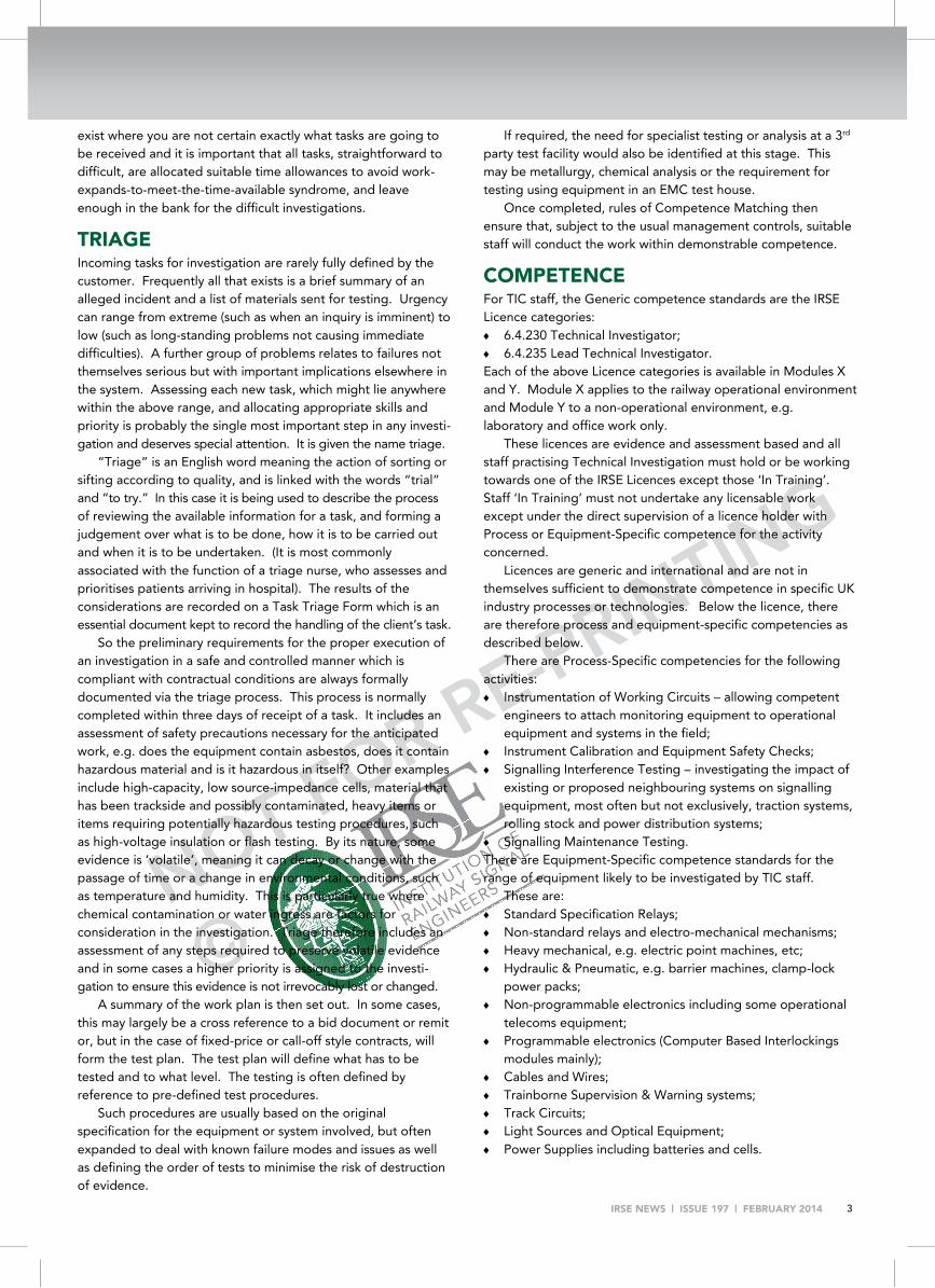
exist where you are not certain exactly what tasks are going to be received and it is important that all tasks, straightforward to difficult, are allocated suitable time allowances to avoid work-expands-to-meet-the-time-available syndrome, and leave enough in the bank for the difficult investigations.
TRIAGE Incoming tasks for investigation are rarely fully defined by the customer. Frequently all that exists is a brief summary of an alleged incident and a list of materials sent for testing. Urgency can range from extreme (such as when an inquiry is imminent) to low (such as long-standing problems not causing immediate difficulties). A further group of problems relates to failures not themselves serious but with important implications elsewhere in the system. Assessing each new task, which might lie anywhere within the above range, and allocating appropriate skills and priority is probably the single most important step in any investi-gation and deserves special attention. It is given the name triage.
“Triage” is an English word meaning the action of sorting or sifting according to quality, and is linked with the words “trial” and “to try.” In this case it is being used to describe the process of reviewing the available information for a task, and forming a judgement over what is to be done, how it is to be carried out and when it is to be undertaken. (It is most commonly associated with the function of a triage nurse, who assesses and prioritises patients arriving in hospital). The results of the considerations are recorded on a Task Triage Form which is an essential document kept to record the handling of the client’s task.
So the preliminary requirements for the proper execution of an investigation in a safe and controlled manner which is compliant with contractual conditions are always formally documented via the triage process. This process is normally completed within three days of receipt of a task. It includes an assessment of safety precautions necessary for the anticipated work, e.g. does the equipment contain asbestos, does it contain hazardous material and is it hazardous in itself? Other examples include high-capacity, low source-impedance cells, material that has been trackside and possibly contaminated, heavy items or items requiring potentially hazardous testing procedures, such as high-voltage insulation or flash testing. By its nature, some evidence is ‘volatile’, meaning it can decay or change with the passage of time or a change in environmental conditions, such as temperature and humidity. This is particularly true where chemical contamination or water ingress are factors for consideration in the investigation. Triage therefore includes an assessment of any steps required to preserve volatile evidence and in some cases a higher priority is assigned to the investi-gation to ensure this evidence is not irrevocably lost or changed.
A summary of the work plan is then set out. In some cases, this may largely be a cross reference to a bid document or remit or, but in the case of fixed-price or call-off style contracts, will form the test plan. The test plan will define what has to be tested and to what level. The testing is often defined by reference to pre-defined test procedures.
Such procedures are usually based on the original specification for the equipment or system involved, but often expanded to deal with known failure modes and issues as well as defining the order of tests to minimise the risk of destruction of evidence.
If required, the need for specialist testing or analysis at a 3rd party test facility would also be identified at this stage. This may be metallurgy, chemical analysis or the requirement for testing using equipment in an EMC test house.
Once completed, rules of Competence Matching then ensure that, subject to the usual management controls, suitable staff will conduct the work within demonstrable competence.
COMPETENCE For TIC staff, the Generic competence standards are the IRSE Licence categories: 6.4.230 Technical Investigator; 6.4.235 Lead Technical Investigator. Each of the above Licence categories is available in Modules X and Y. Module X applies to the railway operational environment and Module Y to a non-operational environment, e.g. laboratory and office work only.
These licences are evidence and assessment based and all staff practising Technical Investigation must hold or be working towards one of the IRSE Licences except those ‘In Training’. Staff ‘In Training’ must not undertake any licensable work except under the direct supervision of a licence holder with Process or Equipment-Specific competence for the activity concerned.
Licences are generic and international and are not in themselves sufficient to demonstrate competence in specific UK industry processes or technologies. Below the licence, there are therefore process and equipment-specific competencies as described below.
There are Process-Specific competencies for the following activities: Instrumentation of Working Circuits – allowing competent
engineers to attach monitoring equipment to operational equipment and systems in the field;
Instrument Calibration and Equipment Safety Checks; Signalling Interference Testing – investigating the impact of
existing or proposed neighbouring systems on signalling equipment, most often but not exclusively, traction systems, rolling stock and power distribution systems;
Signalling Maintenance Testing. There are Equipment-Specific competence standards for the range of equipment likely to be investigated by TIC staff.
These are: Standard Specification Relays; Non-standard relays and electro-mechanical mechanisms; Heavy mechanical, e.g. electric point machines, etc; Hydraulic & Pneumatic, e.g. barrier machines, clamp-lock
power packs; Non-programmable electronics including some operational
telecoms equipment; Programmable electronics (Computer Based Interlockings
modules mainly); Cables and Wires; Trainborne Supervision & Warning systems; Track Circuits; Light Sources and Optical Equipment; Power Supplies including batteries and cells.

NOT FOR RE-PRINTING
©
IRSE NEWS | ISSUE 197 | FEBRUARY 2014 4
JANUARY TECHNICAL PAPER These headline categories are subdivided by additional letter codes and it can be seen that the range of equipment is significant – it can be anything from “Solid Steel to Solid State” and to be able to complete successful investigations across this diverse range of equipment requires a team of specialist staff. Staff are typically drawn from service centres, infrastructure company technical support or maintenance backgrounds, or design, graduate and technician training schemes.
The triage does not merely identify a list of tests to complete, it is a tailored document created on the basis of a review of all of the evidence available at that time. Although some might say that an investigation cannot be fully defined, as it may be reactive and change direction based on findings so far, much like police work, there are still defined procedures to follow and form a coat hanger around which the investigation takes shape.
Once the outline test plan is produced, the skills necessary to complete the investigation work can be identified from within the list of categories in the Technical Investigation competency management system and staff with suitable competencies identified. It is a duty of staff conducting investigations who find that deviations from the original outline plan, anticipated range of skills, or task prioritisation are necessary to draw this to the attention of the original Engineer responsible for triage such that the triage document can be updated.
On completion of the triage process, the task is allocated to the relevant competent persons and investigation will commence.
INVESTIGATION The competent person nominated to complete all or part of
the task will utilise calibrated and safety-checked equipment from our inventory, in our case maintained using a combination of in-house and external calibration companies, with rigs, jigs and fixtures to carry out tests. Work will generally then be completed using pre-produced test procedures and plans or against pre-defined test sheets.
The following example is for an SSI Signal Module (SM) received in connection with a reported aspect irregularity:
After obtaining site connection details, full details of the reported incident, site recorder records and paying due diligence to the safety review and volatile evidence warning, the SM would be inspected and tested against documented procedures which include a re-ordered version of all of the tests shown in the original test acceptance specification – this forming about 40% of the total number of tests carried out.
Further checks and tests would also be completed as part of the documented procedures which relate to known areas of performance which are not detailed in the SM’s specification. These tests form a further 40% of the total tests completed.
The above work would be completed using the set procedure and, in this case, constitutes what we consider to be a full functional test from the module’s connector i.e. a full assessment of all of its functions – be they used or not in the site arrangement. In this case, and typically, this type of work is carried out manually, with only small but repetitive parts of the test procedure, like soak tests at reduced and elevated voltage, being automated. The system is constantly checking for correct performance in these situations. This is deliberate to maximise
the chances of intermittent problems coming to light during the investigation and being observed and there are many examples of this: a module recently tested appeared to perform satisfactorily in terms of its response to control telegrams, as the contents of its replies and its panel indications suggested, but its output performance was actually intermittent and problematic as it was producing spurious outputs over an extended period but these were not detected by the internal checks within the module.
Typically, further work is then completed as follows: The final 20% of testing might then be what could be called
the added value – where the findings are related to the original failure. This may take the form of completion of a site simulation with things like data, power, temperature or other variables, or other reference to the site configuration and available data from site. This is an important area and is enforced by procedure – so although we would routinely test all areas of performance regardless of allegation, we always endeavour to establish the site application and relate the effects of any specified / unspecified performance issues to the original allegation. Where a serious problem is identified, attempts will be made to identify the root cause to component level if required.
In cases of equipment of high capital value, it is now accepted that, should this equipment perform satisfactorily during all standard examinations and tests, then seals remain in place and the unit may be re-used following completion of a suitable post-incident retention period. If there is any doubt about the performance, the equipment would be sent for service following investigation.
Finally, a report will be produced detailing all test findings, our professional opinion in relation to the performance of the equipment against specification, other known operational characteristics and the possibility of any deficiencies identified either causing or contributing to the reported failure. These reports are produced by the investigator and team, then subject to approval, authorisation and review. The principal investigation engineer is responsible for ensuring that quality review of Technical Investigation Reports takes place. In some cases a preliminary risk assessment is recommended where the impact of a particular failure and consequentially any actions required may not be determined easily.
This kind of analysis is vital because virtually no equipment tested is ever truly “NFF” – No Fault Found. Almost every item tested has one or more deficiencies in performance when compared to its specification so the term more likely to be used where a piece of equipment performs satisfactorily is “No cause found” i.e. nothing found that caused or contributed to the incident reported.
Sometimes a final judgement on performance may be based on specification but also comparison with other similar units. This added-value also forms a vital feedback function where issues are ongoing. Examples for the SSI Signal Module might be ongoing checks on opto-isolator ageing, or transient voltage suppressor or other EMC component checks.

NOT FOR RE-PRINTING
©
IRSE NEWS | ISSUE 197 | FEBRUARY 2014 5
PROTOCOL FOR THE INVOLVEMENT OF MANUFACTURERS AND SERVICE AGENTS IN INVESTIGATIONS Although we pride ourselves on our ‘library’ of test equipment, rigs, jigs and perhaps most importantly, data / specifications, relating to equipment and systems in use, there are limitations. Many specifications today are ‘performance specifications’ describing what the equipment shall deliver rather than the prescriptive ‘how to’ specifications typical of the BR days. These have allowed a greater level of innovation and encouraged broader diversity of the signalling supply base, but of necessity in such a market-place, much of the detailed equipment design information is commercially confidential and not available in the ‘railway domain’ as it once was.
In the situations set out below, special measures are taken to minimise the risk of destruction of evidence and to avoid allegations that the independent technical investigator has damaged the equipment during dismantling, causing it to fail to comply with its specification or known operating characteristics: where it is necessary to dismantle sealed / potted
components requiring special machinery or techniques not available to TIC staff or
the TIC has no data on an item and the supplier is unable to supply it due to copyright or other non-disclosure agreement, or
where the TIC does not readily have the ability to test the item due to a requirement for specialist equipment, or a bespoke jig or rig or
where a new or amended failure mode is discovered or suspected that is not fully documented or known about within the industry and where this failure mode is, or is suspected to be, attributable to a manufacturing or servicing defect.
In these situations, the Original Equipment Manufacturer (OEM), or service agent for repaired / refurbished items, is contacted and invited either to witness an investigation or to arrange a witnessed investigation at their premises.
In some cases, it might not be appropriate to conduct a witnessed investigation. Typically, this might occur when the failure mode is simple, self-evident and unlikely to be controversial or it is impractical, or the service agent / manufacturer declines the offer of a witnessed investigation but wishes to co-operate fully with Atkins in the investigation. In such cases, full liaison is maintained.
The investigation will then proceed and the third party will be kept informed of the findings by witnessing the investigation or being informed of the findings by normal communication routes.
It is possible that the equipment or system may have been used in an application for which it was not intended or which was beyond its designed operating parameters. In normal investigations, where the investigator is in possession of all of the relevant data, the independent investigator would determine this and comment accordingly. Where the manufacturer’s protocol is invoked then the investigator attempts to determine this information as to the likely cause of the problem, but, in order to maintain our independence, a copy of the draft report, usually without conclusions and recommendations, is sent to the supplier / service agent for comment. To limit delays, a response
time of five working days is specified and efforts are made to address all comments or observations raised by the manufacturer or service agent.
The investigator should, however, reserve the right to exclude any third party commentary, and to draw whatever conclusions it considers may follow properly from the evidence assessed as long as this can be justified to the third party. The independence of the investigator should, however, remain paramount.
For this protocol to work properly for the benefit of all parties, it is crucial that it is non-adversarial and conducted as a genuine search for the truth rather than an exercise to apportion blame. It relies upon mutual respect between the investigating engineers and the technical staff of the service agent or manufacturer, and on everyone adopting an open-minded approach to the task whilst preserving the commercial confidentiality of the details of the manufacturer’s design. This protocol has been used successfully for many years across a wide range of equipment manufacturers.
CHANGING WORKLOAD The scatter graph in Figure 1 shows in orange the number of items received in our investigation centre in each year from 1997 to 2013. The linear fit confirms a substantial decline, the number of items received today being approximately half that seen 15 years ago.
The number of reports produced in each of those years (dark blue) also declines, but not in such a marked way. Clearly, the average number of items per report (light blue) has to reflect the decline in equipment received.
This all suggests a declining workload but the picture is not as bleak for our trade as it first appears, it is merely a reflection of the changes that have taken place on the infrastructures that create our workstreams. It is possible that improved maintenance and reliability could be responsible for part of the reduction, but changes in technology undoubtedly affect the number of items received. For example, an incident involving relay-based technology may result in three or four relays being received – a typical incident involving newer technology like SSI
Figure 1: Items received, reports produced and items per report

NOT FOR RE-PRINTING
©
IRSE NEWS | ISSUE 197 | FEBRUARY 2014 6
JANUARY TECHNICAL PAPER almost certainly results in a single item being submitted.
Furthermore, evidence from looking at many cases during the triage process also indicates another factor has perhaps had the most significant effect - that of the plethora of monitoring systems now fitted to infrastructure and vehicles: event and condition monitoring systems, On-Train Monitoring Recorders, front-facing cameras etc. Such equipment has largely eliminated the scattergun approach of equipment change seen in yesteryear with targeted equipment recovery. Of course, the scattergun approach still occasionally occurs usually when serious failures result in large-scale equipment changes and recoveries leaving the engineer with a pile of hardware of unknown status. Evidence from these systems is also often sufficient to challenge successfully allegations made by operational staff who may think the system has malfunctioned when in fact they have made an error. This has resulted in a reduction in the number of ‘precautionary investigations’, the purpose of which was positively to rule out any signalling malfunction rather than to look for the cause of a failure suspected by the maintainer after exhaustive site testing.
Given that many systems are now monitored, is there a need to submit equipment for independent specialist testing at all? Well generally, yes. The findings of monitoring systems have to be treated suitably. One infrastructure operator’s standard with regard to data loggers puts it succinctly:
“It shall be understood that sole reliance cannot be placed upon data, in instances such as accident investigation and maintenance reduction, where the system from which it is derived is not designed to an appropriate Safety Integrity Level. However, such data can be used as an aid to focus investigation and analysis provided that this qualification is explicit, other supporting evidence can be produced, and the conclusions of an investigation or analysis process do not rely solely upon it. Analysis of logged data shall not be used as an alternative to full testing prior to the reinstatement to service of any infrastructure.”
The vast majority of such monitoring systems are single-channel systems which often derive data in a way that cannot guarantee that the indications given by the monitoring truly represent the performance of the signalling system. For example, a typical standard specification miniature plug-in relay could have up to 16 contacts and the event recorder will only be connected to one of these. As such, the event recorder gives an inference as to the state of the contacts within that relay based on the single contact monitored. Similarly, in solid state systems the monitoring is likely to be single channel and indications in such systems rarely fully close the loop. Thus, internal failures or cabling faults can result in unexpected outputs with no contra-indications.
Limitations aside, site monitoring means that the equipment received is perhaps now more likely than ever before to be at fault - which invariably means extended investigation times – so it is not a case of “work expanding to meet the time available.” When looking at the issues identified, they may not have caused the site incident which resulted in the equipment being submitted, but the equipment could still be found to be affected by some issue that would or could cause problems either in a different configuration or given time to develop. Thus it is clear that even the “no cause found” investigations provide useful
feedback on the state of that type of infrastructure or the infrastructure in the area in question. This is important in these days when servicing and sampling of equipment no longer routinely takes place and life-extension is commonplace and a number of developing problems have been identified from “no cause found” investigations over the years.
TECHNICAL SUPPORT Firstly, technical support activities are managed using similar controls as outlined for technical investigation in respect of triage and competence. This type of task tends to ‘arrive’ by phone or e-mail as opposed to the arrival of an item through the door – though there are sometimes crossover tasks which involve both items received and site work.
Given that the average number of items per report is falling, but our workload does not seem to be, a count of the number of reports produced which had no equipment submitted as part of the task was completed. The graph in Figure 2 shows the outcome of this query and it can be seen that this work has always been there, but is on the increase.
Looking at the subject matter covered by the “zero equipment” reports shows that many of these investigations involved the site investigation of equipment or systems which had failed or were still failing to operate as expected. Many of these investigations used the Process-Specific competencies mentioned earlier and specialist monitoring or measurement techniques which may not have been available locally. The sort of tasks we are involved in changes all of the time - technology transfer also having a significant effect where things that would, at one time, be significant work areas, become more commonplace and specialist services are less in demand.
A key ingredient in the success of these projects is often the experience gained by completing detailed technical investigations in the laboratory on systems of the type involved or, in some cases, similar systems or by knowing about the environment into which a system has been placed.
Working closely with equipment and systems in the laboratory equips the tester with an in-depth and detailed knowledge of the way in which equipment performs under a wide variety of conditions – often extreme conditions at the
Figure 2: Reports produced where no equipment was received

NOT FOR RE-PRINTING
©
IRSE NEWS | ISSUE 197 | FEBRUARY 2014 7
edge of the specification which are unlikely to exist in real-life applications. The investigator becomes attuned then to observing the foibles of performance which may not in themselves be atypical of the hardware in question but just may not be seen by most people. Furthermore, Technical Investigation staff are more likely to have seen many generations and types of seemingly similar or supposedly compatible items of equipment building detailed knowledge of performance, both in specified and unspecified areas.
The remaining zero-equipment reports were largely monitoring, screening and data gathering exercises – these being special tests or monitoring for safety case / immunisation work or specialist site surveys to examine EMC, wire degradation, contamination, or other issues.
So this work comes in all shapes and sizes, from one-day visits to tasks that escalate following an initial visit. Here are some notable examples that have resulted in significant system modifications.
A request was received to investigate the intermittent failure of the Data Links of a relatively new SSI system during initial test runs of a new type of train. Using specialist test equipment (now commonplace), it was quickly determined that the problem was related to common-mode interference in frequency bands not seen with earlier rolling stock (but now also commonplace). As the train was deemed to be compliant with EMC specifications, the affected signalling systems had to be modified. Within days, simulation work had shown that a susceptibility in the Data Link Module caused the production of pulses when exposed to common-mode noise – the worst case being around 20 kHz. A solution was developed and trialled in the form of transformer common-mode noise blocks – firstly using Data Link Isolation Transformers (DLITS) then subsequently a variety of plug-in modules. Over the following year or so we assessed numerous other SSIs in conjunction with route-proving trials of the new train and modified SSI systems as necessary using specially developed Signalling Maintenance Testing Handbook test plans.
A request to review EMC testing carried out on a widely deployed axle-counter system that was proving to be unreliable identified a potential issue. Although tested in accordance with the specification requirements, it was considered that the parts of the system susceptible to the type of interference in question, had not been tested. Pulse Magnetic Field Immunity tests were subsequently completed and a potential issue identified. Further work was completed and culminated in the construction of low and high frequency radio antennas to allow assessment of magnetic field interference in accordance with TS50238-3 – a specification we helped validate. A significant problem was subsequently confirmed by site tests and the axle-counter manufacturer produced modified firmware to overcome the problem identified. The infrastructure owner has widely deployed this modification at a large number of susceptible sites.
TRENDS IN INVESTIGATION / SUPPORT Whilst preparing this paper there was a wish to test some hypotheses on data from our task management system. My first hypothesis was to look at the number of tasks and associated equipment and the analysis confirmed my belief that, between 1997 and 2013, the absolute number of items we test has
reduced, the number of reports is similar and reports where no equipment was received are on the increase. A further hypothesis I wanted to test was that there would be a decreasing number of reports produced where electromechanical items were involved and an increasing number of reports where electronic and programmable systems items were involved.
However, it was by no means certain that the foregoing would be the case, given that most electronic and programmable systems still have a number of relays involved – particularly in train detection, point control / detection and interfaces. Moreover there is probably a declining, but still substantial, population of electromechanical items and they are ageing, and so perhaps more prone to problems and thus to be sent for investigation.
So analysis of available data was completed where the percentage of reports produced each year detailing the testing of equipment from the various groups, as defined earlier in the section in this paper regarding triage, was completed.
The graph in Figure 3 shows the outcome of this analysis with axes as follows: The x-axis shows the equipment categories (as above under
“Triage”); The y-axis shows the percentage of reports in each calendar
year analysed that involved equipment from the relevant category;
The z-axis shows the waterfall of data from 1997 at the back to 2013 at the front.
A slight decline in investigations of standard electromechanical relays and a significant level of programmable electronic systems equipment fitted the hypotheses, examples of equipment from other categories being involved in less than 10% of reports.
Much of the equipment being in the less than 10% of reports category is a problem in itself as these are the items which are more likely to be difficult in that you may not be so readily set up to test them or may not even be able to - these tasks are some of the most problematic.
Perhaps the most interesting thing to come out of this analysis however, is the increasing number of items in the Light Sources and Optical Equipment category (letter “l”) which is circled. Work received in this category has increased to the very top of the 10% band in recent years and will probably become
Figure 3: Reports detailing investigation of equipment by category, 1997-2013

NOT FOR RE-PRINTING
©
IRSE NEWS | ISSUE 197 | FEBRUARY 2014 8
JANUARY TECHNICAL PAPER one of only three categories in the burgundy-coloured 10-20% band this year based on work already received. This increase appears associated with the large–scale roll out of LED-type signals in lieu of filament lamp types.
This rollout is enforced by the obsolescence of the filament lamp. The introduction of any new technology can be problematic, but in effect these units are a like-for-like replacement for an existing product. Looking more closely at some of the reports produced in this category is an edifying experience. Some items have manufacturing faults, and a few have developed faults due to environmental ingress, and a number of ‘phantom’ aspect issues have occurred. However, amongst these failures are a fair number of problems that I would classify as compatibility issues relating to the introduction of new technology on to existing infrastructure which has areas of “known and/or unspecified” performance.
“KNOWN AND/OR UNSPECIFIED” PERFORMANCE TRAITS As outlined in the technical support section of this paper, during completion of numerous tests and simulations, you become attuned to observing the foibles of performance which may not in themselves be atypical of the hardware in question but just may not be seen by most people, may not have any adverse effect when ‘discovered’ and perhaps more importantly, may not directly be mentioned in any specification or documentation. Here are three that I consider have impacted on successful LED signal rollout.
1 Non-true RMS evaluation of current proving paths in Signal Modules
1.1 Signal Modules (SMs) sample the voltage appearing across a range of fixed, or user-defined, resistors and pass this via a multiplex to a comparator, that is they use a threshold. If a suitable number of the samples are ‘above the line’ in a measurement period, then current proving is achieved. However, change the current waveform for something of a similar true root mean square (RMS) magnitude, as in Figure 4, and you can be in trouble.
1.2 This became apparent in 1995 when signals connected to SMs at one end of Liverpool Street station started to be intermittently indicated as ‘black’. The failure only occurred late in the evening or in the night and when the signals were observed it was apparent that they remained lit at all times.
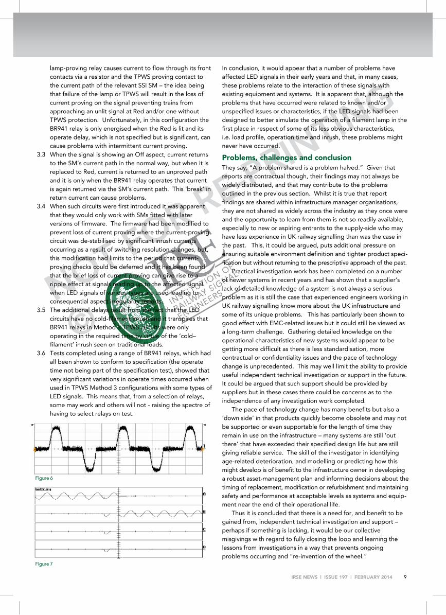
1.3 Examination, and subsequent logging of the power supply showed that it was affected by very significant distortion in the evening and night – Total Harmonic Distortion (THD) values of up to 13% being logged (Figure 5). A predominance of odd harmonics contrived to give the power supply waveform ‘shoulders’ – so although the RMS value was similar, much of the current flowing through the signal head was now not above the threshold (Figure 6).
1.4 This was an unusual problem and was traced to a shared transformer in the power supply feed which also fed many non-linear lighting loads. Replacing SL35-style loads with that of LED signals can, however, produce a similar effect. The non-linear ‘peaky’ nature of the loads presented by such signals occasionally impacts on current-proving indications.
Comparison of current measurements on the waveform below showed differences of 30% between that indicated by a true RMS meter and that by an older form-factor-corrected mean responding type.
2 Spurious triac firing in some MkII Signal Modules 2.1 During early post-incident tests on some MkII SMs (from
1991), it was noted that, when the module carried out Power Disable Tests or was exposed to power supply interruptions, spurious output triac firing would occasionally occur. This was caused by presentation of voltage with a high rate of change to the output triacs, where the voltage coupled via small leakage capacitance between the terminals of the triac and caused it to gate itself. The device would then switch off at the next zero crossing, and the effect only occurred if the application of voltage occurred close to the peak of the incoming supply (see Figure 7).
2.2 As such, full voltage outputs of 5 to 7 ms duration occurred. At the time, these were dismissed as they produced no observable effect when applied to typical filament lamp signals of the kind in use at that time.
2.3 We have just concluded documenting the third aspect irregularity caused by this phenomenon and it has been seen to affect main, subsidiary and position light junction signals of the LED type - the response time of these signals being so much shorter than that of the filament lamp types they replaced.
3 British Railways type BR941 relay 3.1 This relay was specified and designed to be used as a lamp-
proving relay, and in such applications would be energised all the time, unless there was a total lamp failure. The relay was specified to have a slow release to ensure it did not release during aspect changes causing spurious lamp-proving failures and changes of aspects on signals reading up to the signal in question.
3.2 This relay was subsequently utilised in Method 3 TPWS circuitry to eliminate the need for large scale SSI data changes when TPWS was rolled out. However, in this application the relay is typically associated with only the Red, and is only energised when the signal is displaying that aspect. In Method 3 TPWS the energisation of the Red
Figure 5
Figure 4
NOT FOR RE-PRINTING
©
IRSE NEWS | ISSUE 197 | FEBRUARY 2014 9
lamp-proving relay causes current to flow through its front contacts via a resistor and the TPWS proving contact to the current path of the relevant SSI SM – the idea being that failure of the lamp or TPWS will result in the loss of current proving on the signal preventing trains from approaching an unlit signal at Red and/or one without TPWS protection. Unfortunately, in this configuration the BR941 relay is only energised when the Red is lit and its operate delay, which is not specified but is significant, can cause problems with intermittent current proving.
3.3 When the signal is showing an Off aspect, current returns to the SM’s current path in the normal way, but when it is replaced to Red, current is returned to an unproved path and it is only when the BR941 relay operates that current is again returned via the SM’s current path. This ‘break’ in return current can cause problems.
3.4 When such circuits were first introduced it was apparent that they would only work with SMs fitted with later versions of firmware. The firmware had been modified to prevent loss of current proving where the current-proving circuit was de-stabilised by significant inrush currents occurring as a result of switching resolution changes, but, this modification had limits to the period that current-proving checks could be deferred and it has been found that the brief loss of current proving can give rise to a ripple effect at signals reading up to the affected signal when LED signals of various types are used leading to consequential aspect irregularity reports.
3.5 The additional delays result from the fact that the LED circuits have no cold-filament inrush and it transpires that BR941 relays in Method 3 TPWS circuits were only operating in the required time by virtue of the ‘cold–filament’ inrush seen on traditional loads.
3.6 Tests completed using a range of BR941 relays, which had all been shown to conform to specification (the operate time not being part of the specification test), showed that very significant variations in operate times occurred when used in TPWS Method 3 configurations with some types of LED signals. This means that, from a selection of relays, some may work and others will not - raising the spectre of having to select relays on test.
In conclusion, it would appear that a number of problems have affected LED signals in their early years and that, in many cases, these problems relate to the interaction of these signals with existing equipment and systems. It is apparent that, although the problems that have occurred were related to known and/or unspecified issues or characteristics, if the LED signals had been designed to better simulate the operation of a filament lamp in the first place in respect of some of its less obvious characteristics, i.e. load profile, operation time and inrush, these problems might never have occurred.
Problems, challenges and conclusion They say, “A problem shared is a problem halved.” Given that reports are contractual though, their findings may not always be widely distributed, and that may contribute to the problems outlined in the previous section. Whilst it is true that report findings are shared within infrastructure manager organisations, they are not shared as widely across the industry as they once were and the opportunity to learn from them is not so readily available, especially to new or aspiring entrants to the supply-side who may have less experience in UK railway signalling than was the case in the past. This, it could be argued, puts additional pressure on ensuring suitable environment definition and tighter product speci-fication but without returning to the prescriptive approach of the past.
Practical investigation work has been completed on a number of newer systems in recent years and has shown that a supplier’s lack of detailed knowledge of a system is not always a serious problem as it is still the case that experienced engineers working in UK railway signalling know more about the UK infrastructure and some of its unique problems. This has particularly been shown to good effect with EMC-related issues but it could still be viewed as a long-term challenge. Gathering detailed knowledge on the operational characteristics of new systems would appear to be getting more difficult as there is less standardisation, more contractual or confidentiality issues and the pace of technology change is unprecedented. This may well limit the ability to provide useful independent technical investigation or support in the future. It could be argued that such support should be provided by suppliers but in these cases there could be concerns as to the independence of any investigation work completed.
The pace of technology change has many benefits but also a ‘down side’ in that products quickly become obsolete and may not be supported or even supportable for the length of time they remain in use on the infrastructure – many systems are still ‘out there’ that have exceeded their specified design life but are still giving reliable service. The skill of the investigator in identifying age-related deterioration, and modelling or predicting how this might develop is of benefit to the infrastructure owner in developing a robust asset-management plan and informing decisions about the timing of replacement, modification or refurbishment and maintaining safety and performance at acceptable levels as systems and equip-ment near the end of their operational life.
Thus it is concluded that there is a need for, and benefit to be gained from, independent technical investigation and support – perhaps if something is lacking, it would be our collective misgivings with regard to fully closing the loop and learning the lessons from investigations in a way that prevents ongoing problems occurring and “re-invention of the wheel.”
Figure 7
Figure 6
NOT FOR RE-PRINTING
©
IRSE NEWS | ISSUE 197 | FEBRUARY 2014 10
LIFECYCLE PLANNING
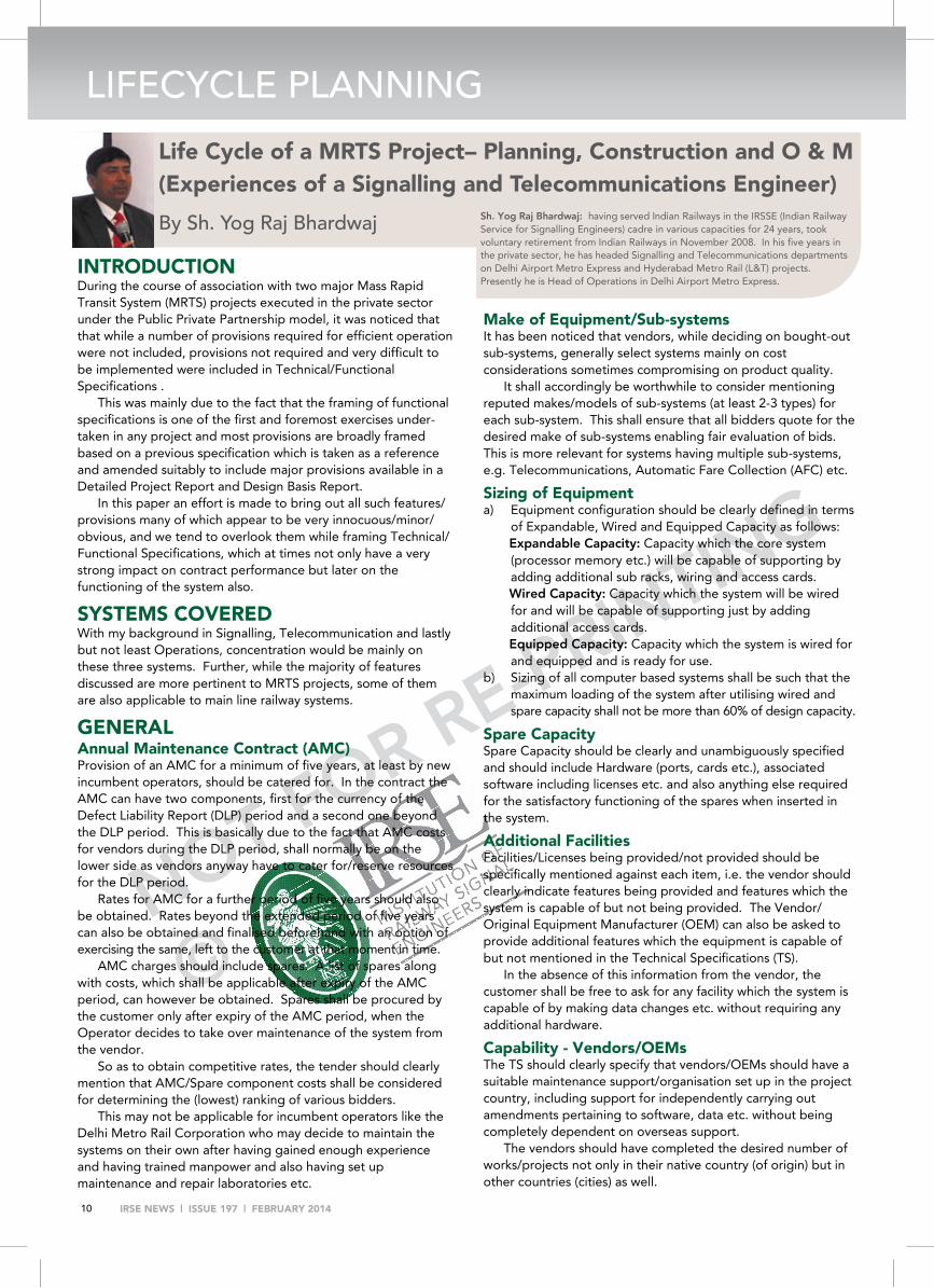
INTRODUCTION During the course of association with two major Mass Rapid Transit System (MRTS) projects executed in the private sector under the Public Private Partnership model, it was noticed that that while a number of provisions required for efficient operation were not included, provisions not required and very difficult to be implemented were included in Technical/Functional Specifications .
This was mainly due to the fact that the framing of functional specifications is one of the first and foremost exercises under-taken in any project and most provisions are broadly framed based on a previous specification which is taken as a reference and amended suitably to include major provisions available in a Detailed Project Report and Design Basis Report.
In this paper an effort is made to bring out all such features/provisions many of which appear to be very innocuous/minor/obvious, and we tend to overlook them while framing Technical/Functional Specifications, which at times not only have a very strong impact on contract performance but later on the functioning of the system also.
SYSTEMS COVERED With my background in Signalling, Telecommunication and lastly but not least Operations, concentration would be mainly on these three systems. Further, while the majority of features discussed are more pertinent to MRTS projects, some of them are also applicable to main line railway systems.
GENERAL Annual Maintenance Contract (AMC) Provision of an AMC for a minimum of five years, at least by new incumbent operators, should be catered for. In the contract the AMC can have two components, first for the currency of the Defect Liability Report (DLP) period and a second one beyond the DLP period. This is basically due to the fact that AMC costs for vendors during the DLP period, shall normally be on the lower side as vendors anyway have to cater for/reserve resources for the DLP period.
Rates for AMC for a further period of five years should also be obtained. Rates beyond the extended period of five years can also be obtained and finalised beforehand with an option of exercising the same, left to the customer at that moment in time.
AMC charges should include spares. A list of spares along with costs, which shall be applicable after expiry of the AMC period, can however be obtained. Spares shall be procured by the customer only after expiry of the AMC period, when the Operator decides to take over maintenance of the system from the vendor.
So as to obtain competitive rates, the tender should clearly mention that AMC/Spare component costs shall be considered for determining the (lowest) ranking of various bidders.
This may not be applicable for incumbent operators like the Delhi Metro Rail Corporation who may decide to maintain the systems on their own after having gained enough experience and having trained manpower and also having set up maintenance and repair laboratories etc.
Make of Equipment/Sub-systems It has been noticed that vendors, while deciding on bought-out sub-systems, generally select systems mainly on cost considerations sometimes compromising on product quality.
It shall accordingly be worthwhile to consider mentioning reputed makes/models of sub-systems (at least 2-3 types) for each sub-system. This shall ensure that all bidders quote for the desired make of sub-systems enabling fair evaluation of bids. This is more relevant for systems having multiple sub-systems, e.g. Telecommunications, Automatic Fare Collection (AFC) etc.
Sizing of Equipment a) Equipment configuration should be clearly defined in terms
of Expandable, Wired and Equipped Capacity as follows: Expandable Capacity: Capacity which the core system (processor memory etc.) will be capable of supporting by adding additional sub racks, wiring and access cards. Wired Capacity: Capacity which the system will be wired for and will be capable of supporting just by adding additional access cards. Equipped Capacity: Capacity which the system is wired for and equipped and is ready for use.
b) Sizing of all computer based systems shall be such that the maximum loading of the system after utilising wired and spare capacity shall not be more than 60% of design capacity.
Spare Capacity Spare Capacity should be clearly and unambiguously specified and should include Hardware (ports, cards etc.), associated software including licenses etc. and also anything else required for the satisfactory functioning of the spares when inserted in the system.
Additional Facilities Facilities/Licenses being provided/not provided should be specifically mentioned against each item, i.e. the vendor should clearly indicate features being provided and features which the system is capable of but not being provided. The Vendor/ Original Equipment Manufacturer (OEM) can also be asked to provide additional features which the equipment is capable of but not mentioned in the Technical Specifications (TS).
In the absence of this information from the vendor, the customer shall be free to ask for any facility which the system is capable of by making data changes etc. without requiring any additional hardware.
Capability - Vendors/OEMs The TS should clearly specify that vendors/OEMs should have a suitable maintenance support/organisation set up in the project country, including support for independently carrying out amendments pertaining to software, data etc. without being completely dependent on overseas support.
The vendors should have completed the desired number of works/projects not only in their native country (of origin) but in other countries (cities) as well.
Life Cycle of a MRTS Project– Planning, Construction and O & M (Experiences of a Signalling and Telecommunications Engineer)
By Sh. Yog Raj Bhardwaj Sh. Yog Raj Bhardwaj: having served Indian Railways in the IRSSE (Indian Railway Service for Signalling Engineers) cadre in various capacities for 24 years, took voluntary retirement from Indian Railways in November 2008. In his five years in the private sector, he has headed Signalling and Telecommunications departments on Delhi Airport Metro Express and Hyderabad Metro Rail (L&T) projects. Presently he is Head of Operations in Delhi Airport Metro Express.
NOT FOR RE-PRINTING
©
IRSE NEWS | ISSUE 197 | FEBRUARY 2014 11
Interface Working Proof of working of not only stand-alone systems but with all interfaces, particularly inter-system interfaces, should be specifically called for, along with information on details of corresponding interfacing systems.
Man Machine Interfaces (MMIs) All system MMIs should have a user friendly Graphical User Interface (GUI) with availability of operator defined features (without expert intervention). GUI design shall be finalised after receipt of a minimum of three drafts from the vendor.
Phase Commissioning Some projects with multiple lines and common Operations Control Centres (OCC) shall sometimes require phased commissioning of various systems along with a facility of operation from a temporary location, other than the final OCC, until the final OCC is commissioned. Details/methodology of phase commissioning of various sub-systems shall be elaborated.
Vandal Proofing All equipment in outdoor and public access locations shall be Vandal Proof.
Licences (Software/Hardware) All software/hardware licences shall be valid for the life-
time of the project. All systems should be provided with an Anti-virus solution
with auto updates for the lifetime of the project. Licences, valid for the lifetime of the project, shall be made
available for all hardware features (including spare ports, cards, capacity etc.).
The vendor shall hand over soft copies of all software applications, system, monitoring, diagnostic etc., along with the necessary documentation, to the Operator for use as a back-up in event of the crashing of any system.
Sealing of Openings All external openings and cut-outs in equipment rooms shall be sealed with a proper sealing arrangement. Details of the sealing arrangement shall be provided for the approval of the customer.
Approval of Design/Drawings Approval of design and other project documents shall be subject to the condition that approved designs/drawings shall conform/comply to all provisions of the Tendered/Contract specifications unless non-compliance is specifically mentioned in the approval.
Tendering Common or separate tenders for Signalling and
Telecommunications systems should be deliberated upon and decisions taken accordingly.
Further, within Telecommunications, for new operators separate tenders for individual sub-systems are not recommended, so as to avoid interface and coordination issues. There should preferably be integrated tenders for all sub-systems. However organisations/operators with sufficient experience can consider separate tenders for individual sub-systems.
Redundancy - Hardware and Software Based on reliability requirements, redundancy in terms of
hardware and software of all sub-systems shall be clearly and unambiguously defined.
All systems shall have dual/redundant power supply modules working in sharing mode.
All modules shall be hot-swappable so as to avoid the need to switch off equipment when replacing modules.
Redundant modules should be provided in different sub racks/backplanes so that a rack backplane failure does not result in failure of both modules.
Racks/Sub-Racks All racks shall be provided with transparent toughened front glass
doors. This shall facilitate monitoring of module indications without having to open the doors.
The level of Electromagnetic Compatibility (EMC) compliance for the racks shall be provided along with necessary certifications.
Air Conditioning units should not be mounted above equipment racks. If this is unavoidable, then suitable canopies must be provided to prevent damage in case of any flooding or leakage.
All individual sub-system assemblies mounted in sub-racks shall be EMC compliant.
Cable Wiring All Internet Protocol wiring shall be to CAT-6 standard with
shielding. Optical Fibre Cables (OFC) used for Access network (long pig-tails)
shall be armoured/screened both for strength and protection. Cables used for systems should be screened/armoured.
(screening factor to be indicated). All cables laid outside the cable tray should be either in conduit
or in flexible pipe. No cable shall be exposed/hanging in the open. Sizes of all cable cores should be specified, particularly for cable
cores used in signalling. Adequate spare cable cores at all levels (min. 50%) should be
provided. For telephone system, last leg access network should use CAT-5
cable. In open section, Fire Retardant Low smoke cables should be used
in MRTS projects.
Mounting Structures All mounting structures/arrangements used in public areas should be at least Stainless Steel (SS) and be compatible with the general station ambience.
General Rooms An incident handling room which can also be used as a meeting
room should be provided in OCC complex. This room should have a normal entry from outside the OCC with an entry from the OCC side also (to be used only in case of emergency).
Grouping of rooms – Critical and Non-critical – All Critical and Non-critical rooms both at the OCC and stations should be co- located for better Heating Ventilation and Air Conditioning design.
False ceilings in back of house areas should be avoided for ease of maintenance as also for cost considerations.
1

NOT FOR RE-PRINTING
©
IRSE NEWS | ISSUE 197 | FEBRUARY 2014 12
LIFECYCLE PLANNING Even in public areas false ceiling should be designed
so as to enable easy access to all cable trays and other assets above the false ceiling.
Uninterruptible Power Supply Systems Plan for a common Uninterruptible Power Supply
(UPS) system for all three systems – Signalling, Telecommunications and AFC.
Dual redundant UPS system with redundant batteries (2V cells) should be planned for maintenance purposes.
Dual redundant chargers with associated battery system also to be planned for d.c. systems.
As there will be two sources in the Input and also a dual redundant UPS/Charger system, two separate input feeders with suitable changeover should be planned.
Day/Night voltage switching should be catered for in elevated sections.
A common circuit with UPS back up should be provided for energising critical equipment of various departments in mid section. This circuit should be tamper proof to avoid tripping due to illegal tapping/usage etc.
Security Policy of Information Technology Systems The vendor shall submit a security policy to be followed during project/Operation and Maintenance (O&M) phase for all Information Technology related systems.
Central/Remote Maintenance of Systems Elements of all sub-systems should be suitably networked so as to enable remote monitoring and maintenance of all sub-systems from a central location, preferably from OCC or central Maintenance location. Similarly a Central Integrated Maintenance System/Terminal should be planned for integrated monitoring and maintenance of all sub-systems.
TELECOMMUNICATION SYSTEMS Dual Redundancy All sub-systems shall have dual redundancy with auto-
matic changeover in event of a problem in one system. All servers and workstations should have dual
Ethernet ports so as to enable connection to both redundant networks.
Digital Transmission System (DTS) The DTS shall be predominantly Internet Protocol (IP)
based system, suitably configured to provide for required redundancy with assured/dedicated band-width to various applications without compromising on Quality of Service parameters thus eliminating the use of Synchronous Digital Hierarchy components.
In the case of an IP based system, the back bone capacity should be able to take care of the complete bandwidth requirement of all systems including spare capacity and other bandwidth hungry applications viz. CCTV system etc.
Interface with other Non-Communication Systems As far as feasible, a dark fibre based interface shall be
planned for non-communication systems. Use of dark fibres for various system networks shall enable ease of maintenance during the O&M phase with clear cut defined responsibilities.
However in the event of an IP network, interfaces with other systems shall not require separate OFC and dedicated VPNs with adequate bandwidth that can be configured for various applications/networks.
Proof of actual working of interfaces with proposed systems viz Automatic Train Operation/Automatic Train Protection (ATO/ATP) – Rolling Stock (RS) –Communication and Automatic Train Supervision (ATS) – Public Address/ Passenger Information Systems should be insisted upon from the vendor.
All interfaces and connectivity should preferably have a standard IP interface. Use of Propriety interface protocols should not be allowed.
OFC Sizing and Commercial Exploitation Additional (separate) OFC should be planned for commercial exploitation. With its protected ROW, telecommunication infrastructure is considered of premium quality and various telecommunication companies prefer leasing MRTS infrastructure even at higher rates.
Wi-Fi and Cellular Facilities Provision of Wi-Fi facilities and Cellular Operator’s coverage at various stations should be provided for use by passengers. (This is important for underground MRTS systems)
Access Network All devices should be IP based (as far as possible). All IP based access equipment shall be Power over Ethernet (PoE)
enabled and shall not require separate power cable. All switches shall be equipped with equivalent PoE enabled ports so
as to enable direct powering up of IP based end devices.
Public Address (PA) System Feedback/monitoring arrangements both for auto and manual
announcements should be available. Monitoring of the health of speakers (suitable indication on speaker)
including its connectivity should be available for all speakers. Speakers using Surface technology (feonic.com) can be considered
for adoption in some areas. Ways and means to reduce station wiring should be adopted. Type of speaker, mounting arrangement, colour etc. should suit the
ambience of individual locations/stations. Separate servers and work stations should be provided for PA and
Public Information and Display (PID) systems. Free space recording should be provided for OCC and SCR
(Controllers) and Train Operators (RS). Wireless PA microphones should be provided at stations, to enable
announcements on the move, by station staff in case of emergency.
Passenger Information and Display System (PIDS) The PIDS screen should be a professional PIDS assembly, rather
than simple commercial LCD screens. PIDS screens should have proper IP45 compatible housing suited to
and compatible with the surrounding ambience. Configuration of templates for free text/content display on PIDS
screens should be easy and user friendly. Free text messages should be easily configurable both from OCC/
SCR (with proper authorisation) and should be able to be displayed on selected PIDS terminals.
In event of a PIDS – Signalling Interface failure, it should be possible manually to update the time from a central location (OCC) with a pre-defined (standard train running) logic, so that all stations en-route are displaying information as per a predefined algorithm.
Closed Circuit TV (CCTV) System Ways to reduce outdoor wiring should be adopted. Adopting a
completely IP based system with IP cameras can be one option. Use of OFC ring based systems to connect various cameras in a ring

NO
T FO
R R
E-P
RIN
TIN
G©
IRSE NEWS | ISSUE 197 | FEBRUARY 2014 13
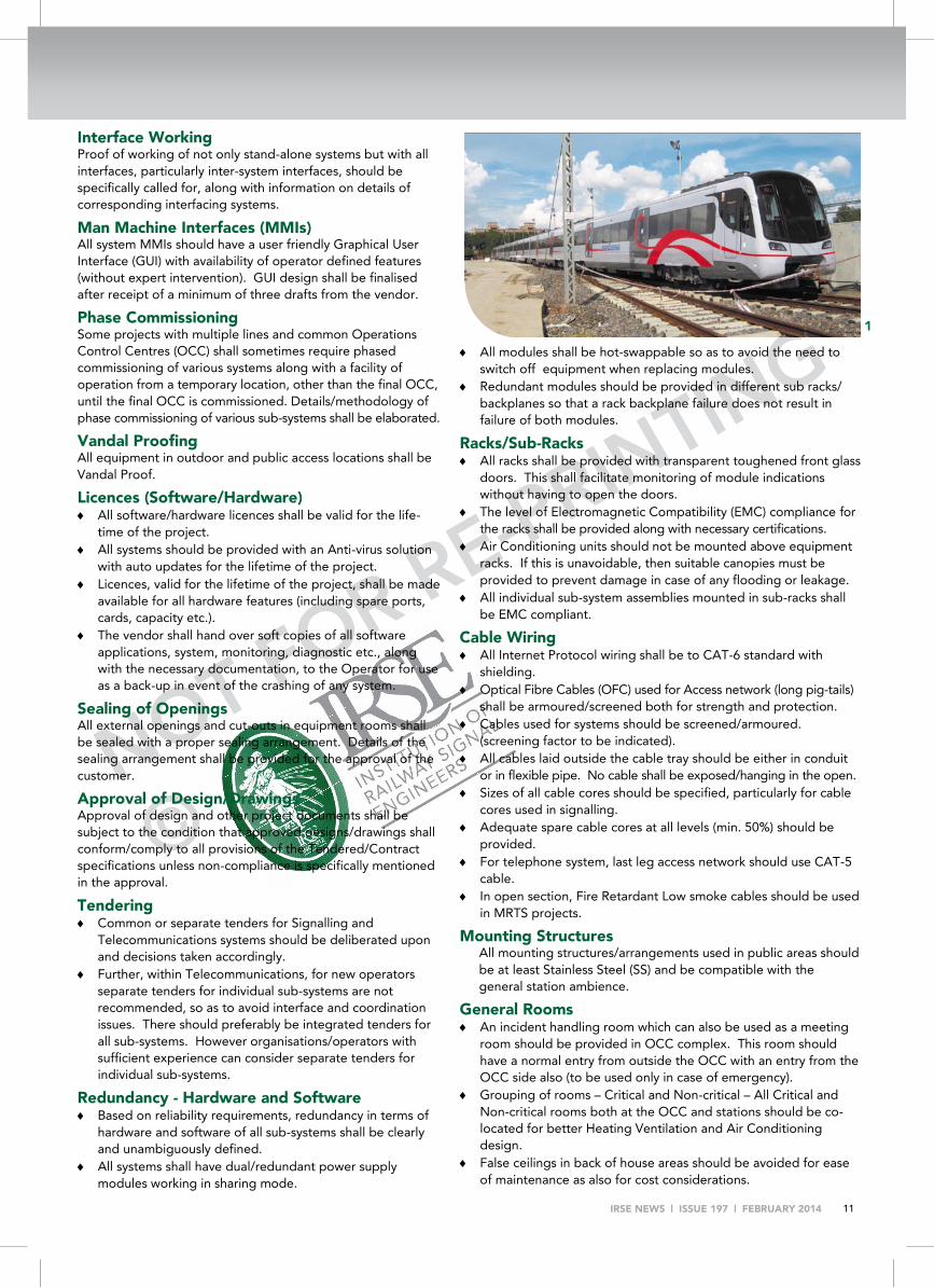
Delhi Airport Metro Express Line Project 1 Train on Test Track (CAF – Spain)
2 Laying of Optical Fiber Cable (Samsung – China) on a viaduct
3 Train-borne ATP MMI – Driver’s Console 4 Automatic Fare Collection Gate (Indra – Spain) 5 Underground station
can be considered within stations. This shall reduce wiring and also provide the required redundancy.
Types of mounting arrangement for cameras (top, bottom, wall etc.) should be carefully selected, depending on the individual location.
The size of ‘Pan/Tilt/Zoom’ camera housing and its mounting should be in proportion to surroundings.
Facility of CCTV transmission from train (RS) – OCC may not be required.
CCTV coverage study to be finalised only after validation by a Security Agency.
Video analytical features should be properly studied and the system configured accordingly to ensure the features are effective after implementation.
A video wall for the central security room should be planned. It should be possible to zoom in one camera on more than one
video screen/panel. CCTV monitoring of viaduct sections can be planned on security
considerations. CCTV monitoring of OCC, Station Control Rooms (SCR) and
other operational rooms along with the cab of RS should be provided.
RS should be provided with cab side cameras to enable the monitoring of train doors from the cab. (This will eliminate requirement of head/tail wall screens at stations without PSDs)
Telephone System Central Voice Recording System (CVRS) should have E1(2 MBPS) /
Internet Protocol interface with Private Automatic Branch Exchanges (PABX), Radio and PA systems with a facility so that all pre-defined calls can be recorded.
All Private and Group calls including calls from/to Radio Dispatcher Workstation in the radio system shall be recorded by the CVRS system.
Co-ordination for Public Service Telephone Network connectivity of PABXs at EI level shall be in the scope of the vendor.
Minimum 50% of all cables should be spare, both for the last mile and back bone network.
For last mile connectivity STP Cat-5 cable or minimum four pair screened cable should be used.
Multi party conference (>3) and other standard features for the telephone system along with required licenses should be available in the system.
Licenses for all equipped and spare ports along with features specified in the TS should be available.
All exchanges should be interconnected using an IP interface. Provision of a recording and play back room should be made for
play back and analysis of recordings.
Clock System Size of clocks – both analogue and digital should be carefully
selected depending on individual locations. Analogue Clocks should have numerals with LED lighting. All systems including Train Borne Signalling and RS systems
should be synchronised with a common synchronising clock.
Radio The Train Radio Control Panel for the cab should be planned for
ease of operation. Co-ordination with spectrum authorisation should be in the
scope of the vendor Radio coverage study in all station areas and back of house
areas/rooms should be done and submitted for approval. All Radio Calls including Private, Group & calls to/from the
RDW should be recorded. The interface of the radio system with the CVRS ( Central
Voice Recording System) should be at E1 (2 MBPS) level.
Testing and Maintenance Tools Provision of the following testing tools should be ensured:
Optical Time Domain Reflectometer;
Splicing Machine (both Mechanical and Electrical);
Optical Power Source and Meter;
Radio Coverage/Strength measurement meter;
Audio Strength measurement meter;
Local Area Network tester.
2
3
4

NOT FOR RE-PRINTING
©
IRSE NEWS | ISSUE 197 | FEBRUARY 2014 14
LIFECYCLE PLANNING SIGNALLING SYSTEM General The System should broadly conform to all National Railway
Specifications, i.e. the IRS etc., and other international specs. Alternate /standby signalling (line side signals) with a suitable
Standard Operating Procedure should be planned to cater for ATP failure.
Back-up OCC should be planned – features and facilities to be made available should be clearly defined.
The boundary of every station should be clearly defined and should be congruent both physically and technically. Elements of a station shall be controlled by Element Control Computer/Interlocking (ECC/IXL) of that station only.
In event of any communications link/system failure at the OCC, individual station controls should be passed on to the relevant SCR automatically, with a suitable alarm message both at the OCC and the concerned station.
The Overview Display screen should be ergonomically designed to suit ambience of the OCC with proper visibility, contrast etc. from various Controller’s desks/work stations.
Proper ergonomically designed furniture should be provided for all controller positions both at the OCC and SCRs.
System Functionalities The System should support bidirectional signalling, so as to
enable ATO, ATP and other signalling functionalities for train movements in both (normal and reverse) directions on a line.
A minimum of 3-aspect signalling for manual signals should be provided. Aspects of a signal for ATP/ATO mode should be decided after due deliberations.
The signalling system should be so designed so as to have minimum wayside equipment.
The signalling system should be Platform Screen Door (PSD) compatible. Specific requirements for connecting to a PSD system should be clearly specified with financial implications. The cost for interfacing the signalling system to the PSD system should be obtained and considered for tender evaluation.
All components of signalling and associated sub-systems including the overview Display system and PSD system should be centrally monitored from a fault reporting terminal in the OCC.
Timetable, Data Preparation and Simulation System A user friendly offline timetable forming, testing and validation
system should be available. It should be possible to formulate/implement timetables with
variable white periods with an option of 24 hour train service. Timetables should be possible to be formulated for various
speeds considering various Temporary Speed Restrictions and other parameters like coasting, cruising etc.
Off line Automatic Route Setting (ARS), ATS, ATO, and ATP simulation systems should be available for training purposes.
Data preparation and compilation facilities which can be used during commissioning of the system should be provided. Same can be used later during O&M phase for carrying out changes in various signalling sub-systems with necessary change control authorisations and certifications. Software changes are not envisaged at field level.
All project specific application data pertaining to IXL, ATP, ATS, ATO and ARS functionality should be made available for approval.
Diagnostic software should be provided for fault diagnosis for all sub-systems. Normally diagnostic software used by the vendor during manufacturing and testing at their premises should be supplied to the client along with the system.
The ATP/ATO system should be responsive to various changes in speed, coasting, cruising and other variable parameters in the Timetable without any need for changes in ATO/ATP system.
Timetable systems should be able to generate timetables for various trip combinations, i.e. should be able to incorporate scheduled short and split trips.
The Training Simulator should include an EI/ATP simulation.
ATS, ATO and ATP Sub-systems Stopping points should be configured for end of platform
so that the same stopping point can be applicable for different configurations of rolling stock (3/6/8 car)
ATP to ATO transition should preferably be possible anywhere in mid-section.
The system should be configured so that the train does not stop in a Neutral zone.
The Mode of operation (ATP/ATO/Restricted Manual (RM)/Cut Off) should be displayed on the overview display screen in the OCC.
Counters for RM and Cut Out operation should be available in the ATO/ATP MMI.
RS should have counters to keep a count of operation of all Emergency switches on the Train Operator’s desk.
Provision of electronic counters for number of operations of point machines should be available.
A train stopping in the section/station beyond a preset stopping time should be suitably indicated on the overview display screen and also generate an audio visual alarm for the Controller.
Positive Train Identification (PTI) functionality should be properly tested during the commissioning stage to avoid malfunctioning which may resulting in wrong train ID stepping and route setting (in ARS mode).
PTI information should be planned to be obtained using both Train to Track (PTI loop) and Train to Radio (as a confirmation) communication.
Placement of IXL and ECCs in the section should be so as to ensure a commercially and technically optimal solution for signalling control.
Every station must preferably be provided with an Element Control Computer Interlocking (ECC) for Distance to Go system or back-up system in case of Communication-Based Train Control so as to avoid unnecessary inter-station cabling.
The following displays should be additionally available on ATP/ATO Human Machine Interface (HMI) : Actual stopping deviation (in +/- mm);
Separate Indications for TD and PSD status;
Indication of ATP – Train Control and Management System (TCMS) communication status link on ATP HMI.
Record and play back facilities for the ATP HMI archive should also be available. This shall ensure the availability of the ATO/ATP archive HMI for analysis purposes.
Handling of Neutral Section (NS) – Power Gap from the Signal system for controlling trains in Neutral sections should be synchronised with NS detectors provided by RS.
The ATO system should be able to synchronise immediately with active timetable in the ATS system without any degradation and need for adaptation required by the ATO System to adapt to any change in timetable parameters, particularly with respect to speed.
Provision should be made for torque testing of point

NOT FOR RE-PRINTING
©
IRSE NEWS | ISSUE 197 | FEBRUARY 2014 15
machines. Torque testing instruments should be available. Application for automatic download of ATO/ATP logs to a
maintenance terminal in the Depot from trains, using a Wi-Fi link should be available.
ATO diagnostics should have the functionality to monitor all parameters continuously and monitored data should be available both in tabular and graphical form with a facility to suitably alter (minimise/maximise) the scales of various para-meters to enable proper and accurate analysis of incidents.
AUTOMATIC TRAIN SUPERVISION SYSTEM It should be ensured that setting a route for stopping trains at
platforms is initiated only after train has actually stopped at the designated stopping point and 15 seconds (adjustable) prior to the actual departure time. This shall avoid the skipping of trains in the event of the train ID being lost and reinserted manually just prior to the stopping of the train. In other words it should be ensured that under no condition a train planned to be stopped as per timetable, skips a station in ATP/ATO mode.
Rather than only the active timetable, it should be possible to take a print out of any of the timetables available in the ATS system from the ATS terminal.
The Play back system for train movement (archive) files should have all Record & Playback functionalities i.e. Play, Pause, Fast Forward and Rewind. It should be possible to configure archive files of variable sizes from 5-20 minutes.
It should be possible to configure/classify various alarms in the system on the ATS MMI as Operational and Technical. These two categories of alarms can subsequently be classified as Normal and Urgent. Urgent Operational Alarms should immediately pop on a large Alarm Window with an audio alarm for acknowledgment by the Operator/Controller. Similarly on the Maintainer’s console, Technical Urgent alarms should pop up on a large Alarm Window.
The Mode of Train Operation should be logged in the archive log and should also be suitably displayed on an overview display screen.
The relationship between Rake and Service Identification of trains running in the system should be readily available both on-line and in the archive for the information of Traffic controllers and for analysis purposes.
All connectivity links (including redundant links) of interfacing systems, particularly IP based, should be monitored independently on the network diagram. Data received and transmitted on these links should be able to be seen as part of online diagnostics.
All MIS report formats should be finalised only during the O&M stage in consultation with the Operator/Operation Dept.
Trains should continue to be localised (identified) in sidings and transfer tracks by providing suitable localisation loops or other approved arrangement.
There should be immediate localisation of trains, after a system failure is rectified, so as to ensure fast recovery/normalisation of train operations.
The Dwell time should start from actual stopping of the train at the stopping point and not from hitting the berthing track.
Provision should be made for suitable resilience while handling TX errors. EB should be initiated only after a config-urable delay of non-receipt of TX telegrams, to avoid EB application due to transient failures of telegram transmission.
Time Synchronisation of train-borne Signalling, Telecomm. and Rolling Stock systems (TCMS) should be ensured.
Provision of an ATS MIS port should be made for an online interface to the SAP/Enterprise Resource Planning (SAP/ERP) system for customised online reports.
Operational Stopping Points should be normalised immediately after departure of the train even if the platform track circuit has failed, to avoid run through/skipping of trains.
Stopping accuracy at a platform should be linked to the PTI Loop used for controlling the PSD in conjunction with synch-ronisation loops or any other devices used for controlling the stopping of the train at a subsequent platform.
CONCLUSION All points brought out above are a result of experience during the planning, construction and operation phase of TG based MRTS projects. While some of above points may not be applicable/relevant to all projects, considering Technical and Functional specifications available, the author feels that incorporating the above factors while framing DTG Signalling and Telecommunications Specifications for MRTS projects would go a long way, both in the smooth execution of the project and also in seamless trouble free transfer to the Operation phase.
PS : The above views are purely of those of the author, based on
his experience and may be considered not relevant/acceptable by some learned colleagues. Feedback however is welcome at [email protected].
5

NOT FOR RE-PRINTING
©
IRSE NEWS | ISSUE 197 | FEBRUARY 2014 16
Preconvention Musings (by Priyank Patel)
The time honoured tradition of learning from others (especially by visiting them in person), in this case through the International Convention, is a pertinent one for Younger Members (YMs). I will enjoy it more so as I still have fresh memories of being on the organisation committee for the previous convention. Take a back seat and enjoy being a delegate rather than having the unenviable task of planning and the equally unenviable anti-social task of ushering the delegates to ensure timekeeping.
The Hewlett Fisher Bursary is a godsend for YMs such as me. Without it, financial constraints would mean difficulty in justifying the expense to myself and (more importantly) convincing my wife that this would be anything more than just a jolly. Having taken up a multitude of opportunities to attend the technical visits in the UK, I am over the moon to be given this opportunity to go abroad. Whilst at Heathrow Airport for my 06:40 departure I thought I should write down and share my expectations from the convention. My expectations were as grand as the occasion: To meet other professionals from around the world; Compare and contrast Scandinavian railways to the UK railways; Discover the expectations and share experiences of other
YM from around the world; Encourage them to take a more active role in supporting the
IRSE NEWS (this being my ulterior motive, being the YM Assistant Editor of the magazine).
16 September 2013 (Report by Priyank Patel) David Weedon was kind enough to invite the bursary winners to an informal preconvention lunch at the Malmö Radisson Blu hotel, another godsend considering the budget provided to the winners. Planning the trip to the Kroner was essential for me. It was here that the bursary winners agreed to compile this report together allowing me to collate and edit. Readers will be pleased to know that this includes YM opinions of writers from UK, Australia, Hong Kong and Thailand, a mere sample of the nineteen nationalities represented at the convention
The rest of the delegates and their guests that got to Malmö in advance were able to enjoy a pre-convention reception of drinks and finger food. Dave gave a quick welcome and managed to embarrass the YM bursary winners by inviting them to the front so the other delegates can recognise them. On discovering that I would be writing this report, an interested delegate asked me if I would be reporting any
tabloid style ‘scoops’? A novel idea I thought. After some eavesdropping and probing I am pleased to reveal that the 2014 convention will be in France, followed by one in Australia, then one in China. The programme booklet specified that the reception ends at 19:30, but come 21:00 delegates and guests were still there enjoying the reception.
17 September 2013 (Report by Yvette Griggs) As a very grateful recipient of the Hewlett/Fisher Travelling Bursary, I was recruited to the IRSE Press Gang and assigned the write up for Tuesday.
We entered the conference centre through a lovely little courtyard to the Carolinahallen, Sankt Gertrud Conference Centre where President David Weedon gave the opening address for the convention.
I was allocated to group A1 which meant that our first presentation of the day was from Mr Göran Omberg, the "Operative Chef" of Trafikverket (who it turned out was not a real Swedish chef at all). His presentation highlighted how Trafikverket covers 94 400 km of road and 11 900 km of railway monitored by four road traffic control centres and eight rail traffic control centres. One thing that stood out for me was the Swedish railway principle that trains departing and travelling according to their timetable take precedence when threatened by an already late-running train.
After this presentation, we walked to the Malmö Control Centre. The Control Centre was going through a refurbishment so a lot of it was still under construction. Looking at the offices that had already been done, and the lime feature walls that had been painted, it is going to be a beautiful, inspiring space, quite different to any other control centres I have seen before.
We were given the opportunity to observe the train controllers and had an explanation of the roles of the staff that sit in the control room. The most noticeable difference from the control centres I have seen in Australia is that everyone looks very happy,
Younger thoughts on the 2013 Convention By Priyank Patel, Yvette Griggs, Kennedy Wong, Sunny Kapil and Frazer Howie IRSE Younger Members
IRSE INTERNATIONAL CONVENTION 2013
Bursary winners lunch

NOT FOR RE-PRINTING
©
IRSE NEWS | ISSUE 197 | FEBRUARY 2014 17
relaxed and casual, in their bright coloured hoodies and jeans. This might be a general Scandinavian quality, not just limited to train control staff.
We then headed down a spiral staircase to the "cellar" where all the interlockings are kept. Our tour guide even admitted that this may not be the best location for interlockings as it had flooded previously. We posed for some photos with the racks with flashing lights and received an explanation of the interlockings and their cloud connection.
We then returned to the hotel for a presentation about the Malmö City Tunnel Project. Malmö was originally the station at the end of a line that travelled through some residential areas. The tunnel project allowed a new alternative route to be created underground, adding some additional stations as well. The underlying principle of the underground tunnel option was that travelling underground must be as safe as travelling in the open air. To achieve this, there are five emergency exits and a platform adjacent to the tracks along whole length of the tunnel, allowing passengers to detrain if there is an emergency. 100% of the tunnel is covered by cameras, applying the technology from a South African giraffe counting system to detect trespassers. We also discovered that the Swedish acronym that covers railway infrastructure equipment is "BEST". How appropriate!
For lunch, we were served a traditional buffet, featuring the tastiest mushrooms I have ever eaten, in a rustic dining hall in the conference centre.
In the afternoon, we had more presentations from Mr Per Olafsson, Mr Peter Elestedt and Ms Gina Kruze from Trafikverket and Bombardier, revealing how Sweden had been a leader in the early adoption of a lot of modern signalling equipment. One interesting fact that I learnt was the reason why the Swedish Railway Rules and Regulations were written in English. In 1856, the Köping Hult Railway imported British drivers and other staff because they wanted to use experienced people to make their railway a success from the beginning. I was also surprised by the protection type statistics for the level crossings in Sweden, where 35% do not even have passive protection. However, on the other end of the scale, their use of obstacle detectors with full booms has meant that there has never been a collision at a level crossing with this combination of protection.
In the evening, we had free time to explore Malmö and discuss all that we had learnt about Swedish signalling systems over a dinner of Swedish meatballs.
18 September 2013 (Report by Kennedy Wong) On the third day of the Convention, we paid a visit to the Railway Training School and the Railway Museum located in Ängelholm, Sweden.
The Railway Training School is part of the Sweden Transport Administration and it is the largest of its kind in the country. The training school offers training on various perspectives including signalling and communications, trackwork, driver training etc. The training school not only provides training to the national railway but also to external parties in Scandinavia.
The school kindly offered an opportunity for us to visit the training facilities on signalling as well as trackwork. For signalling, there was an impressive large scale simulator of signalling systems, with different types of interlocking systems provided for
training purpose. The training allows the simulation of not only the normal operation but also failure scenarios to allow fault-finding exercises to take place. For trackwork, we did have a chance to appreciate its basic elements such as rails, fastening clips and the methods of rail welding etc.
The railway museum is another part that cannot be missed. The museum at Ängelholm is one of two railway museums in Sweden, where its focus is on the infrastructure of the railway. The most interesting part was the “Locomotion” where we had an opportunity to experience riding trains at different ages, from steam locomotives to modern Swedish railway trains in a simulated train cab. This reminded us of how the evolution of technology actually brought more comfort to not only the passengers but also the train operators. We also had a chance to watch a movie on the history of railway development with various train models running as the backdrop. We were all amazed by the substantial effort put by the Swedish government on railway education.
In the afternoon, we visited the exhibition on the Hallandsäs tunnel project. The tunnel project will greatly enhance the line capacity of the West Coast Line, but the project had been delayed due to underestimated geological constraints and environmental issues. The speakers shared with us how they overcame all these difficulties through the introduction of modern technologies in tunnel excavation and revised project management regimes. This enabled the breakthrough of one of the tunnels in 2013 and another tentatively in 2015. Although this project has been bringing many challenges to the project team and the local people, valuable experiences have been gained for similar tunnel projects in the future.
The day ended with a dinner at Klitteyrbyn Restaurannt with nice food and drinks. Everyone enjoyed the day so much and looked forward to the next day in Copenhagen.
19 September 2013 (Report by Sunny Kapil) I wish to thank the IRSE for the grant that made this visit possible. As the first international convention that I have attended, it gave me a very good chance to broaden my sight in the enormous area of signalling. During the convention, there were many opportunities to discuss things with the other participating members of the signalling community. These discussions were very inspirational for my future.
All delegates assembled at Malmo Central Station at 07:30 for the trip to Valby Station via Copenhagen. The session in the morning included a talk and tour on the amazing Joint Test Labs (JTL), which facilitates the “The Signalling Programme”, ERTMS Level 2 national roll-out in Denmark. The main purpose of JTL is to provide a facility for system integration between infrastructure, onboard and external systems.
The presentations highlighted organisation structure, usage of JTL that includes final design, lab tests, site tests and supervised operation. They explained the overall test flow and phases, ETCS feeding test (trial runs), joint labour integration testing, Fjernbane specific tests (i.e. on line key management test) and the process verification and validation. The main advantages of JTL are that it provides an easily accessible location to the suppliers, enabling the use of a system integration facility that the supplier does not have at their premises.

NOT FOR RE-PRINTING
©
IRSE NEWS | ISSUE 197 | FEBRUARY 2014 18
The engineer-in-charge showed us around from the JTL and explained the products. This included the MET point machine
produced by Alstom, which is an electromechanical in-sleeper point machine. It is a non-trailable, with internal direct locking,
making it suitable for use in both conventional and high speed lines. The next section was from Frauscher, displaying their latest
generation axle counting system based on a serial interface used for the track vacancy detection. Finally, we had a chance to see
the Thales point machine and axle counter. The next part of the visit was the Copenhagen Control
Centre, our first stop obviously was a coffee, which was perfectly good. We were allowed time to walk around the Control Centre
and see the S-bane project. It is a Communication-Based Train Control (CBTC) system provided by Siemens, which consists of six sections/phases and control areas. Each control area is
divided into several sub-areas, consisting of ATC system (Train guard FM), TMS (Vicos OC), CBI system (Sicas ECC), data
communication systems (FTN and RCS [Airlink]) and facilities system (TOB Intrusion Detection and SCADA).
The control centre is an information storage and display system. Its primary function is to give visual information to the
controllers regarding the time/destination and number of trains at various locations in the area under his control.
The Ramboll Canteen was the venue for lunch, after which it was time to go into the auditorium to listen to papers. David Weedon opened the conference and left it in the good hands of
host Ramboll. The presented papers focused on “what is happening in Denmark”. Martin Munk Hansen of Rail Net
Denmark gave a wonderful presentation on railway investments on an extremely large scale.
The other topics of the presentation were a double track line from Copenhagen-Ringsted, Fehmarn Landworks, freight
corridor between Sweden and Germany, 1-hour model from Copenhagen to Aalborg, speed upgrade of
side lines under the signalling programme. The next presentation was “The Signalling Programme” by
Morten Sondergaard, Rail Net Denmark who gave the overview of the Danish Signalling that needs to be renewed under this programme. Around 60% of all signalling will exceed absolute
final service life within 15 years. It takes 10-12 years to renew all signalling assets where 50% of today’s train delays are due to
signalling failures. The main purpose of this programme is ERTMS Level 2 national roll-out. Implementation of ERTMS
(headed by Ramboll) on all Danish main lines will provide smooth international train transport and a significantly more reliable
service for all passengers. Not only were the delightful and entertaining speakers from
Ramboll and Rail Net Denmark, there was another presentation equally good from Bjorn Uhrig, Siemens who gave the overview
of CBTC on the Copenhagen S-bane. S-bane’s roll-out phase for the last section is 2018.
The presentation reflected the migration of current
configuration to new configuration of parallel signal placement, installation, onboard Driver Machine Interface and dedicated
transition stations (border HKT line/CBTC line). The system can be changed during standstill using the changeover switch.
After a quick coffee break it was back into the auditorium hall to listen to Jan Erik Schneider-Tilli, Rail Net Denmark of the
Copenhagen to Ringsted Project. The line is 56 km long, with five tunnels and 87 bridges. This will be the European best-in-
class standard. Susanne Kalmar Pedersen of Ramboll presented the most
interesting talk, which was about the “TBS Ramboll Fehmarn Belt” project that uses an immersed tunnel to link Denmark and
Germany. The Fehmarn fixed link will provide an environmental friendly and weather independent connection between Denmark
and Germany. The immersed tunnel under Fehmarnbelt is a study in innovative thinking. It challenges existing tunnel building standards, featuring a pioneering longitudinal
ventilation system and state-of-the-art safety and security features. A special grant for this project of 1.1 billion DKK was
awarded for the immersed tunnel, the length of which is totals 17.6 km (a world record).
All in all the conference was a success, we have had a great time. When the visit/presentations came to an end all IRSE
delegates walked to Örestad station to catch train to Sorgenfri station via Copenhagen main station. After a few minutes of
walking from Sorgenfri station we finally found the restaurant at Frilands Museum. Overall, the food during the trip was excellent, ranging from fish to exotic vegetables, pasta, ice-
cream and fruits.
20 September 2013 (Report by Frazer Howie)
The final day of the convention began with another early train ride over the Örestund bridge to Ørestad station in Denmark.
This time the delegates visited the Bombardier building to receive a presentation from Metroselskabet on Copenhagen's
Metro network. The Bombardier building was just as impressive as the Rambøll building we had visited the day before, again
demonstrating the profound Scandinavian commitment to the undertaking of large engineering projects.
The first presentation was given by Metroselskabet's
Operations Manager, Chris Cox, on the Automatic Train Control (ATC) system used on the Copenhagen Metro. He explained
that the current Metro is a driverless system, with ATC delivered via coded track circuits to provide each train with the correct
speed profiles to negotiate each track section. The ATC is split into three system levels, to differentiate between critical and non-
critical functions. These are Automatic Train Supervision (ATS), Automatic Train Operation (ATO), and Automatic Train
Protection (ATP). ATS provides train scheduling and regulation, operation of passenger information displays and the automatic
launching and stabling of trains. The ATO controls train doors, dwell management, speed control via automation of the traction and braking. The ATP contains train detection, route
interlocking, switch control and monitoring, speed supervision, train integrity monitoring and door monitoring.
IRSE INTERNATIONAL CONVENTION 2013

NOT FOR RE-PRINTING
©
IRSE NEWS | ISSUE 197 | FEBRUARY 2014 19
Chris went on to explain the track-side and train-borne equipment required to implement this ATC system. The trains
on the Metro have the ATC equipment duplicated, so that in the event of a failure in one of the systems, the other system can
take control of the train. There is also a manual control panel, should all train protection systems fail. Chris started an
interesting discussion about the concept of equipment redundancy. Is it still necessary to provide an identical duplicate
system to take control in the event of a failure? It is costly for projects to install the same system twice. Would it be more cost
effective to improve system reliability in a single system, rather than installing duplicate systems? Chris also explained that the
performance of the Metro system is determined by a percentage of journeys planned against journeys completed.
The second presentation was given by Marius de Gromoboy
of Metroselskabet on the Cityringen project. The aim of this project is to construct a new Metro system, separate from the
existing Metro, to be operational in 2018. This will involve the construction of two 15.5 km circular tunnels under Copenhagen,
with seventeen new underground stations. It will operate on a 24/7 basis, and will have an operational headway of 100 to 200 s.
The control system of the driverless trains will be CBTC , based on the standard IEEE1474.1. It involves train-based
determination of train location which is independent of track circuits, continuous train to trackside data communication network, and continuous ATP, ATO, and ATS.
As this new metro is underground, special train dispatch conditions are used to ensure the trains will only take passengers
into a tunnel if an exit can be reached. The CBTC system will communicate train failures and fire alarm activations
automatically to the trains. Consideration will also be given to rescue services and how they will be able to access a train in an
emergency. The time available to maintain the new metro will be limited,
due to it running on a 24/7 basis. The project plans to improve maintenance access by placing trackside equipment in station
Priyank’s budgetary lessons learnt for YMs trying to stick to a budget for future conventions:
Shop around for your currency, do not use credit cards or airport currency exchanges;
Book flights well in advance, and there is usually a cheaper hotel option than the ‘Convention Hotel’ and their ‘special rates’;
Be prepared to take antisocial flights; From the airport, take the local bus (or nightbus) – not
the ‘fast train’ service; Travel in groups; Many senior (in company position as opposed to age)
delegates will be claiming meals and have a hospitality budget which you can make use of.
Using a combination of the above I was able to return home with surplus cash, which I was pleased to be in a position to ‘hand back’ to the Institution.
areas, and the use of the CBTC system should also reduce the amount of equipment requiring maintenance. The project also
plans to provide automated train rescue, allowing a failed train to be recovered by a healthy train controlled from the control
centre to reduce the time required to return the metro to full service.
After the day’s presentations, delegates were given a guided tour of the metro's Control and Maintenance Centre, where the
metro trains are sent automatically for daily maintenance checks and cleaning. We were also shown the wheel turning lathe,
training simulator and the operation floor and were given a tour of the emergency control room, which was home to a big red
button with a label stating ‘Do Not Push’. I am glad to report that all the members managed to resist this temptation!
We were then given tickets to experience the metro first-
hand. Some of the bursary winners and I took the opportunity to use the free time to travel into central Copenhagen. The
weather was fine, we had a productive session of sightseeing and got the opportunity to sample some (reassuringly expensive)
Danish beer. We then used the metro to travel to the airport for a mainline train back to Malmö for the evening’s gala dinner.
The Gala dinner was held at the Slagthuset. This was an excellent opportunity to discuss the week’s event with the
delegates and guests, and provided an opportunity to say a fond farewell to new friends made. Speeches were given by David and Ruth Weedon to thank convention organisers and
participants. Christian Sevestre gave a tantalising glimpse of plans for next year’s international convention, promising great
food, fine wine, and high speed rail in Lyon, France. I am sure I am speaking for all the Hewitt/Fisher bursary
winners when I say that we are all very grateful to the IRSE for opportunities afforded to us by being at this convention. I
would heartily recommend application to this bursary fund.
Alexander Walsh, Yvette Griggs and Firas Al-Tahan check out the interlockings in the cellar at Malmö Control Centre

NOT FOR RE-PRINTING
©
IRSE NEWS | ISSUE 197 | FEBRUARY 2014 20
INDUSTRY NEWS
Advert ATA
Oslo’s transport infrastructure owner, Sporveien Oslo AS, has awarded Siemens Rail Automation an order for the supply of signalling infrastructure and train control equipment for the new rail depot at Avløs. The depot will stable the expanding fleet of Siemens’ MX trains. The scope of the contract includes all elements of design, supply, installation, testing, safety approvals and commissioning support for Siemens’ centralised Trackguard WESTRACE system and axle counter train detection, with central control being provided by Siemens’ Controlguide WESTCAD traffic control centre at Tøyen.
Avløs Depot Signalling Contract
In just three months, Siemens Rail Automation has completed the installation of its GSM-R cab radio equipment on all of Banedanmark’s 135-strong S-bane fleet of trains.
Representing the first stage of a 28-month project to equip both the S- and F-bane fleets, this work forms part of a contract to replace all analogue cab radio communications equipment with GSM-R technology, which was awarded by Danish infrastructure operator Banedanmark to Siemens in 2012.
Equipment manufacture and software development has all been undertaken at Siemens’ UK plant in Poole, with installation being carried out by the company’s Danish operation.
GSM-R Installation on Danish S-bane
Deutsche Bahn (DB) is to spend 4.6 billion in 2014 on upgrades to Germany’s national rail network, the company has said. Announcing the investment plan, DB said that throughout the year modernisation work will be carried out on more than 3000 km of track and 2350 points.
Dr Volker Kefer, member of the management board for technology and infrastructure at DB, said “Just for the mainten-ance, we will spend about 200 million more than last year”.
Key projects include: The construction of a third track on the Hamburg-Hannover
line between Lüneburg and Stelle; Improvement works on the Frankfurt-Fulda line’s
Schlüchterner tunnel alongside a refurbishment of Frankfurt Central’s long-distance platforms;
Bridge works on the Rosenheim-Salzburg segment of the Munich-Salzburg line;
Main lines replaced on the Karlsruhe-Mannheim line between Graben-Neudorf and Karlsruhe-Hagsfeld;
Munich-Ingolstadt line upgraded to allow 200 km/h operating speeds;
Integration of the high-speed Erfurt-Halle line with the completed City-Tunnel Leipzig.
Deutsche Bahn announces 2014 infrastructure investment
LUL cancels Signalling contract
It was announced in late December 2013 that London Underground (LU) is to re-let the re-signalling contract for the Circle, District, Hammersmith & City and Metropolitan lines. Bombardier was awarded a contract in June 2011 and has completed preparatory work including the construction of a new control centre, but it is thought compatibility issues have made it impossible to continue.
The work done so far will be taken forward with another contractor due to “the complex nature of the network” and to meet the planned deadline. The original delivery timetable of 2018 will be maintained, LU insisted, and Bombardier retains its separate contract to deliver the new S-Stock trains, which will be introduced as part of the upgrade.
LU’s managing director, Mike Brown, said “This is the right decision to make for London Underground and for Londoners. We have been working closely with Bombardier to find a way forward on what is one of the most challenging and complex pieces of work on the Tube. However it has become apparent to both parties that for the work to be completed within or close to the planned deadline, we need to push on with works with another contractor. Enabling works already completed by LU and Bombardier can be utilised when works recommence. I look forward; of course, to continuing to working with Bombardier who are delivering the walk through air conditioned trains that will serve all four Sub-Surface lines by 2016”.

NOT FOR RE-PRINTING
©
IRSE NEWS | ISSUE 197 | FEBRUARY 2014 21
IRSE MATTERS
How the IRSE works
YOUR COUNCIL (see photo inside front cover)
In issue 196 of IRSE NEWS (January 2014), the organisation structure of the Institution was shown. I now intend to describe the role of the Council, which is the governing body of the IRSE. The constitution, election and responsibilities of the “Council of Management” are defined in the Articles of Asso-ciation, available at http://www.irse.org/about/default.aspx , sections 14 to 16. The Articles were recently updated and approved at the Extraordinary General Meeting held on 13 November 2013, and what follows is a summary of what is contained in the sections particularly relevant to the Council.
Constitution The members of Council are the trustees of the Institution, which is a registered charity in England and Wales, and they are also company directors since the IRSE is registered as a not-for-profit company limited by guarantee, in the UK. Article 14 specifies the Council should consist of a maximum of a President, two Vice-Presidents and up to ten ordinary members of whom ten are Fellows, six are Members and two are Associate Members. In addition Council may co-opt up to three Past-Presidents. The Chief Executive and General Secretary, the Treasurer, local section chairmen and country Vice-Presidents are entitled to attend Council meetings but have no voting powers. In addition, Council can request committee chairmen and others to attend from time to time as they deem necessary.
Election of Council Article 15 defines the way that members of Council are elected. All the Council members are elected by the corporate members of the Institution i.e. Fellows, Members and Associate Members. These members serve for two year terms but are eligible to be re-elected for a number of terms. Every January, Council advises all corporate members of the names of people that Council intends to nominate for any vacancies which will arise at the end of that year, and seeks further nominations from the membership at large. The way that Council goes about selecting the people it nominates was described in detail in IRSE NEWS Issue 121, February 2007 but suffice to say here that it selects people to try and ensure there is a balance on Council of members from different sectors of the profession such that no one sector predominates, as well as trying to ensure a good geographic representation of our nearly 5000 IRSE members.
If more people are then nominated than there are vacancies, a ballot is held, at present by post, and all corporate members are sent a voting form in early March together with details of all the candidates that have been nominated. Completed ballot forms are posted back to the HQ and are counted, with those getting the most votes elected. The results are announced at the Annual General Meeting (AGM) in April, with the new Council taking over after the AGM.
Responsibilities of Council The powers of the Council are specified in Article 16. Essentially Council has the power to do everything necessary to run the Institution, except for those things specifically reserved for a General Meeting, and including the appointment of the Secretary and Treasurer and any other Officers as it deems necessary.
Operation Having summarised the formal obligations of Council, I will now describe how Council operates. It meets in London generally six times a year, with video conferencing facilities provided primarily to permit those resident outside the UK to participate. It has a steady stream of routine business overseeing the work of all the committees, but it is the decision making body of the Institution so committees make recommendations to Council, particularly for important issues. Common sense is used and some powers are delegated to the Officers and to some of the committees to ensure effective operation whilst maintaining the necessary safeguards. A key role is ensuring the Institution continues to develop and maintain its relevance to IRSE members, the profession and indeed society itself. It does this through preparing a Strategy periodically and then monitoring the achievement of that Strategy. The meetings are formally minuted and we have records of all Council meetings since the formation of the Institution in 1912, and before!
I have attended Council meetings myself, in a variety of roles, for over 30 years now and during that time have seen many changes in both people and style. It is rather less formal than it was, although I personally have never found it overly hierarchical and stuffy with Council members being very approachable however senior either in industry or the Institution. In recent years it has benefited by having a greater international participation in its affairs not only through having elected members from outside the UK which has been the case for some time, but more recently through advancements in technology, from having an easier way for international section chairmen and country vice-Presidents to take part. It is impractical for every issue to be debated at length at a meeting attended by between 20 and 30 people and so the committees which report to Council have a responsibility to try and resolve most of the issues and present Council with a considered view on which they can then make a decision. Council often, after a debate, will accept the recommendations made, but that is not always the case and quite lively, although rarely heated, discussions do occur from time to time.
As stated in the title, it is actually your Council which you elect using a simple and transparent process to refresh Council every year. In my experience, it tries its best to do what it thinks will achieve the charitable aims of the Institution, that is, the advancement for the public benefit of the science and practice of signalling (as broadly defined) and the maintenance of high standards of practice and professional care amongst those working within the industry and the promotion of improved safety standards for the protection of the general public.
Colin Porter, Chief Executive and General Secretary

NOT FOR RE-PRINTING
©
IRSE NEWS | ISSUE 197 | FEBRUARY 2014 22
Transport for London (TfL) has congratulated David Waboso, Capital Programmes Director for London Underground (LU), who has been recognised with a CBE in the Queen's New Year's Honours list. David trained as a Civil Engineer, but initially taught mathematics in inner London secondary schools, before resuming his engineering career where he has worked both in the private and public sectors. He initially worked on transportation schemes in the UK and a World Bank sponsored water supply programme in Nigeria. He was then project manager responsible for delivering the DLR's signalling system and in 1995 he won the prestigious award of UK 'Project Manager of the Year'.
He then joined the Jubilee Line Extension team where he was instrumental in getting the extension open in time for the Millennium. David was appointed LU's Director of Engineering in 2005 following a spell at the former Strategic Rail Authority, where he was an executive director. Since then, he has led the largest upgrade in LU's history with major improvements already completed, including the installation of new signalling on the Jubilee and Victoria lines and new trains on the Victoria and Metropolitan lines.
David heads LU's Capital Programmes directorate where he is accountable for delivering the £1.3bn per annum upgrade of the Underground, including stations, train systems and track infrastructure. David recently accompanied both the Mayor of London and the Prime Minister on their visits to India where he helped to develop an understanding between TfL and Mumbai Metropolitan Region Development Authority (MMRA) to build a mutually beneficial partnership.
David holds BSC and MSC in Civil Engineering, is a Charted Engineer, and is a Fellow of the Institution of Railway Signal Engineers, the Royal Academy of Engineering, the Institution of Civil Engineers, the Association for Project Management and the City & Guilds of London Institute.
First Master’s Degree in Signalling and Telecommunications History was made on 11 December 2013 at the Recital Hall in Sydney.
Seung Ho "Luke" Lee was awarded his Masters of Signalling and Telecommunications degree at the Central Queensland University Graduation Ceremony. This award was a culmination not only of Luke's post graduate study, so far, but a significant milestone in the development of the Railway Signalling programme in Australasia.
Luke’s thesis was entitled “Interlocking to RBC Interface design methodology for ETCS Level 2 application”. With the identification of ETCS as one of the key technologies for the future of Australian railways, the thesis was about providing a methodology in enabling smooth integration of ETCS Level 2 onto existing signalling systems. Sydney Train's network was chosen as a case
David Waboso awarded a CBE in the Queen's New Year's Honours List
AUSTRALASIAN SECTION Report by Tony Howker
Luke Lee with his Masters Certificate after the Graduation Ceremony
IRSE Staff Changes The IRSE Council has known for some years that I intended to retire as Chief Executive and General Secretary of the Institution at the end of June 2015, having served in that role since July 2006. Council has now set in train a process to find and appoint a new Chief Executive, so that that there can be a smooth transition in due course. Members will be kept informed about progress through IRSE NEWS.
In addition, our Treasurer, Martin Govas announced last year that he wished to step down from that role at the April 2014 Annual General Meeting having been the Treasurer since 1994. Andrew Smith, a Fellow of the Institution with Siemens Rail Automation in York, was appointed Assistant Treasurer by Council in April 2013 with a view to him succeeding Martin this coming April. A new part-time staff member, Hannah Mueller, joined the Institution in January 2014 as Finance & General Assistant in order to support Andrew in his role as he will continue his work with Siemens.
Colin Porter, Chief Executive

NOT FOR RE-PRINTING
©
IRSE NEWS | ISSUE 197 | FEBRUARY 2014 23
study to test the effectiveness of the methodology and it has identified a number of critical issues and pitfalls engineers should be aware of in success-fully designing the interface between the interlocking and the Radio Block Centres (RBC). Luke is hoping that the methodology could be adopted as the base design for a possibility of standardising the interface design for ETCS across Australia.
Luke Lee is a Student member of the IRSE, 30 years old and lives in Sydney. He first enrolled in the Signalling and Telecommunication programme in 2010 and graduated with the Graduate Diploma in 2012. His CPD6 (Continuing Professional Development) project was a feasibility study on automating the design process for Computer -Based Interlocking simulation, for which he was awarded a Distinction grade for his achievements. He commenced his Master’s year study in February 2012, having met the entry requirements as established by the IRSE. He was with Aurecon when he first started the signalling programme, and was seconded to the Novo Rail Alliance shortly after he commenced his study. His primary work has been with the Sydney rail upgrade projects.
Chris Harvey, an IRSE member from Singapore has also completed his Master’s degree and is aiming to attend his graduation ceremony during 2014. Chris Harvey is a 38 years old British national and is the Platform Screen Door Resident Engineer with Systra-Parsons Joint Venture, seconded to the Dubai Metro project. He met the entry requirements with experience and was admitted to the Graduate Certificate programme in 2010, followed by entrance into the Graduate Diploma programme, where he graduated in 2012. His CPD6 project was on a comparative study of light rail transit systems, for which he was awarded a Distinction grade for his achievements. He was one of the few international students who presented his CPD6 project in person in Sydney. Chris then commenced his Master’s year study in February 2012, having met the entry requirements as established by the IRSE.
Chris Harvey has been admitted to the Master degree but has not yet attended a Graduation ceremony to receive his Testamur. He is planning to do so sometime in 2014 to coincide with a visit to Australia.
Associate Professor Ken Kwong of Central Queensland University was supervisor for both Luke and Chris’ master thesis work.
Luke Lee together with Peter Symons, IRSE Council member attending in recognition of the achievements of the Students
“The Signal Maintenance Engineer - 10 Years of Progress” This paper was presented by Dan Heeley, Signal Maintenance Engineer Doncaster and Ian Puckrin, Signal Maintenance Engineer Leeds on Wednesday 13 November 2013 in York.
Dan started by introducing what a Signal Maintenance Engineer (SME) did and outlined his own career from Graduate Trainee, through Supervisor, Assistant Area Signal Engineer, and then SME first at Sheffield, then Doncaster. He showed the extent of the Doncaster area which had a staff of 90 and covered 300 route miles. A wide range of signalling equipment was in use, including mechanical interlocking, RRI, Westpac 4, SSI and now Modular Signalling. All types of Track Circuit were in use , including Aster ,TI21, d.c., and also various Axle Counter types. There were also 150 level crossings.
Ian then outlined his career to date from Graduate Trainee, Supervisor, and SME. Leeds had 75 staff, 208 route miles, 598 point ends and 1665 track circuits and axle counters but only 7 level crossings. Ian outlined the evolution over the last 10 years from the fault teams and the original ”Instead” data recorders. There were more trains and less track access time, more emphasis on performance, and finite resources. Advances in technology had produced a new generation of sophisticated data loggers that were able to predict failures. The information generated will be able to be transmitted to the new integrated control centres via mobile phone technology, Ethernet and Fixed Telecom Network to servers and hence to alarms/alerts, remote analysis and trends/failure prediction. Ian showed how point motor current was monitored and showed examples of traces with audience participation in prediction of failures from these traces. Examples were given of the cost of point failures, which could run into tens of thousands of pounds for a strategically vital set of points. Other examples were given of track circuit failures including one at Wakefield Westgate caused by leaf contamination which cost of the order of £50k. Cable theft was still a major problem – a 500 m drum of replacement power cable costs £9000! The future aims for the remote monitoring of all points and track circuits and especially level crossings. The trend is also towards usage – driven maintenance.
Dan then resumed by detailing the problems of point maintenance with reference to Grayrigg and Potter’s Bar, and the many SINs that followed. The adjustment of backdrives to obtain free wheel clearance and residual switch opening was explained. The future will see the phasing out of fixed stretcher bars and the introduction of adjustable tubular stretcher bars. The case for specialist equipment teams was mentioned. Dan then outlined how things were, with a 13-week cycle on all equipment based on the “Grey Book” His area still had lampmen for paraffin signal lamps. There remains the challenge to reduce costs, which are 90% labour, with the constraint of resources. For example, AWS track equipment which was on the 13 week cycle is now only visited on failures with no maintenance. The merits of low maintenance cells over wet cells were discussed. We were now moving to annual maintenance, except for points and level crossings, and risk-based maintenance. Data recording and remote monitoring were used to check historic sequences especially for level crossings.
Ian then began summing up. The main objectives had not changed. There was a better understanding of point switch opening. Systems to predict failures were available but could be better utilised. Risk–based maintenance is reducing “Eyes on Assets” The need as ever was to maintain a safe and reliable railway for the lowest cost.
A lively question and answer session followed, with Jim Cowan, Richard Storer, Quentin Macdonald, David Painter, Grace Nodes, Jenny Anderson, Richard Parker, John Armitstead, Ernie Thomson and Blair Robinson taking part.
The vote of thanks to the speakers for a very well received paper was given by Grace Nodes. Following the chairman’s closing of the meeting, opportunity was taken to examine the wide selection of equipment the speakers had brought to the meeting. Thanks recorded to Network Rail for the use of the meeting room.
YORK SECTION Report by Tony Pinkstone
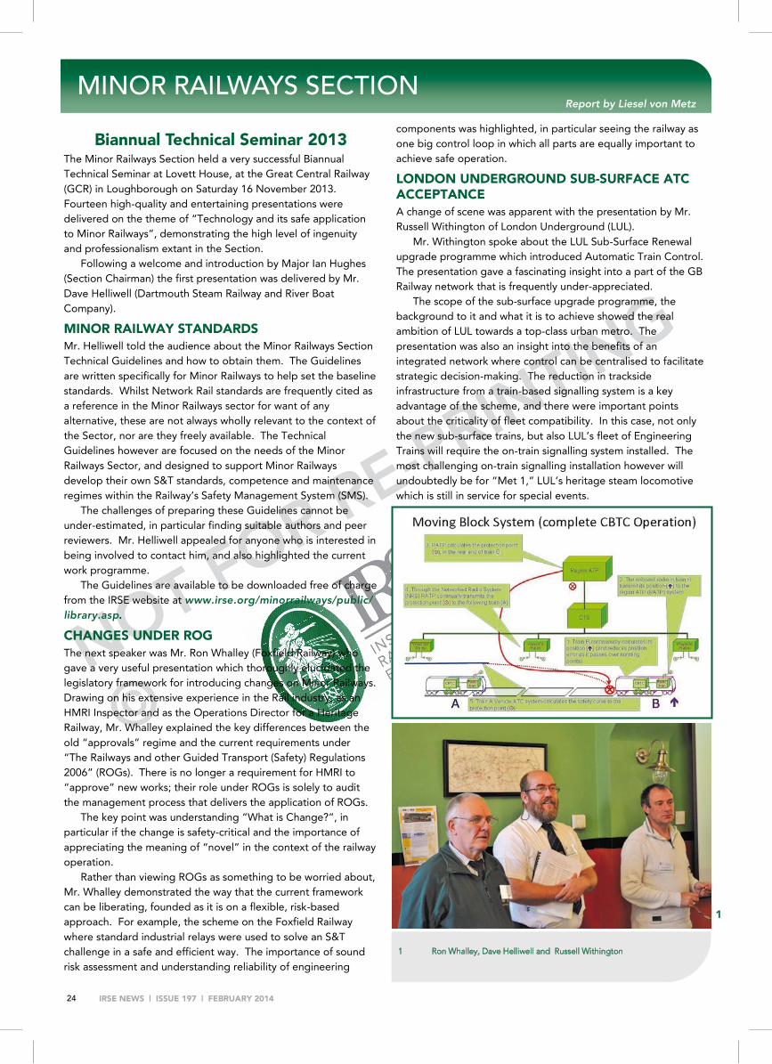
NOT FOR RE-PRINTING
©
IRSE NEWS | ISSUE 197 | FEBRUARY 2014 24
Biannual Technical Seminar 2013 The Minor Railways Section held a very successful Biannual Technical Seminar at Lovett House, at the Great Central Railway (GCR) in Loughborough on Saturday 16 November 2013. Fourteen high-quality and entertaining presentations were delivered on the theme of “Technology and its safe application to Minor Railways”, demonstrating the high level of ingenuity and professionalism extant in the Section.
Following a welcome and introduction by Major Ian Hughes (Section Chairman) the first presentation was delivered by Mr. Dave Helliwell (Dartmouth Steam Railway and River Boat Company).
MINOR RAILWAY STANDARDS Mr. Helliwell told the audience about the Minor Railways Section Technical Guidelines and how to obtain them. The Guidelines are written specifically for Minor Railways to help set the baseline standards. Whilst Network Rail standards are frequently cited as a reference in the Minor Railways sector for want of any alternative, these are not always wholly relevant to the context of the Sector, nor are they freely available. The Technical Guidelines however are focused on the needs of the Minor Railways Sector, and designed to support Minor Railways develop their own S&T standards, competence and maintenance regimes within the Railway’s Safety Management System (SMS).
The challenges of preparing these Guidelines cannot be under-estimated, in particular finding suitable authors and peer reviewers. Mr. Helliwell appealed for anyone who is interested in being involved to contact him, and also highlighted the current work programme.
The Guidelines are available to be downloaded free of charge from the IRSE website at www.irse.org/minorrailways/public/library.asp.
CHANGES UNDER ROG The next speaker was Mr. Ron Whalley (Foxfield Railway) who gave a very useful presentation which thoroughly elucidated the legislatory framework for introducing changes on Minor Railways. Drawing on his extensive experience in the Rail industry, as an HMRI Inspector and as the Operations Director for a Heritage Railway, Mr. Whalley explained the key differences between the old “approvals” regime and the current requirements under “The Railways and other Guided Transport (Safety) Regulations 2006” (ROGs). There is no longer a requirement for HMRI to “approve” new works; their role under ROGs is solely to audit the management process that delivers the application of ROGs.
The key point was understanding “What is Change?”, in particular if the change is safety-critical and the importance of appreciating the meaning of “novel” in the context of the railway operation.
Rather than viewing ROGs as something to be worried about, Mr. Whalley demonstrated the way that the current framework can be liberating, founded as it is on a flexible, risk-based approach. For example, the scheme on the Foxfield Railway where standard industrial relays were used to solve an S&T challenge in a safe and efficient way. The importance of sound risk assessment and understanding reliability of engineering
components was highlighted, in particular seeing the railway as one big control loop in which all parts are equally important to achieve safe operation.
LONDON UNDERGROUND SUB-SURFACE ATC ACCEPTANCE A change of scene was apparent with the presentation by Mr. Russell Withington of London Underground (LUL).
Mr. Withington spoke about the LUL Sub-Surface Renewal upgrade programme which introduced Automatic Train Control. The presentation gave a fascinating insight into a part of the GB Railway network that is frequently under-appreciated.
The scope of the sub-surface upgrade programme, the background to it and what it is to achieve showed the real ambition of LUL towards a top-class urban metro. The presentation was also an insight into the benefits of an integrated network where control can be centralised to facilitate strategic decision-making. The reduction in trackside infrastructure from a train-based signalling system is a key advantage of the scheme, and there were important points about the criticality of fleet compatibility. In this case, not only the new sub-surface trains, but also LUL’s fleet of Engineering Trains will require the on-train signalling system installed. The most challenging on-train signalling installation however will undoubtedly be for “Met 1,” LUL’s heritage steam locomotive which is still in service for special events.
MINOR RAILWAYS SECTION Report by Liesel von Metz
1
1 Ron Whalley, Dave Helliwell and Russell Withington

NOT FOR RE-PRINTING
©
IRSE NEWS | ISSUE 197 | FEBRUARY 2014 25
FILAMENT LAMPS TO LED After a break for coffee and discussion, the event continued with a presentation delivered in three parts. The presentations focused on the challenges of moving from filament lamps to light-emitting diodes (LED) illumination for existing signals; three perspectives on the process where shown.
The perspective of the supplier was presented by Mr. Stuart Marsh (Signal Aspects Ltd). Mr. Marsh opened with the problem statement “sourcing LED lamp modules for colour light signals” and discussed the importance of a sound design brief. Considerations of components are fundamental, taking into account reliability, maintainability and availability in identifying components of a suitable price-range. To be effective as a light source for a colour-light signal, colour testing is critical.
Mr. Marsh did an excellent job of explaining the complex considerations of chromaticity with reference to relevant standards.
Having selected components, he went on to discuss the importance of safety engineering using systematic methodology such as Failure Mode and Effects Analysis and Fault Tree Analysis. He also stressed the need to “write everything down - warts and all!”.
Another point made was that whilst theory is important, never forget the real world; the example of how a red LED aspect was found to flash with specific conditions of cable length and voltage feed was used to illustrate this and to highlight the critical role of a robust trials and testing programme.
The theme of testing and trials was picked up by Mr. Dave Helliwell (Dartmouth Steam Railway and River Boat Company). He opened with the definition of the functional requirement of the LED lamp module for colour light signals: cost, no loss in bright-ness and no phantom aspects.
In putting the LED lamp module into the Minor Railways context, Mr. Helliwell outlined how a thorough risk assessment had concluded that lamp-proving was not required for the LED lamp module. This risk assessment was founded on the criteria that the maximum line speed of the railway was 25 mph (41 kph) (the cut-off point in ROGs below which less onerous regulatory requirements are applied) and the stock using the railway was all fully-braked; worst-case braking data was used. The possible failure modes of the lamp module were discussed and explained in terms of the risk assessment.
Mr. Helliwell then described the field trials of the LED module, and the need to fully describe and document the conversion process.
The final perspective on this theme of moving from filament lamps to LED illumination was delivered by Major Ian Hughes (Green Dragon Rail). He described the role of the Independent Professional Review (IPR) and how the decision of what level of verification/assurance to be used had been made with reference to ROGs Regulation 2. The application of the ROGs “difference test” led to the decision to proceed via the IPR route.
Key lessons highlighted by Major Hughes were the importance of the initial project check sheet and the recording of the reasoning and evidence that led to the decision to proceed with the verification approach used. In carrying out verification, the critical factors are to be proportionate, carry out the work in the right order and according to a systematic plan, but most of all the importance of evidence.
Overall, Major Hughes concluded that with understanding of the process and with a forward looking approach, ROGs and the “Safety Verification” regime was not a millstone that it can sometimes be perceive to be, rather the flexible risk-based approach offers opportunity to develop innovative solutions that take advantage of technological progress.
TERN SYSTEM CONTROL The programme for the morning was rounded off admirably by Mr. Graham Taylor (Tern Systems Ltd) who gave a light-hearted but insightful address based on the question “Is there a place for a man in a shed?”
This interesting presentation was about the development of ideas from initial concept through to a finished product, noting the pitfalls and challenges both to inventors and clients.
The starting point is that “the idea” should be aligned to solve a problem (economically!). Mr. Taylor went on to describe the “dangers” to Clients posed by a “man in a shed”- in short, they tended to be non-collaborative and their idea to be all-pervasive in their lives! However, a “man in a shed” offered many opportunities, not least flexibility, fast speed of develop-ment, exploration of new technology in innovative ways - and cheap (at least in the early stages!). But beware - the work of a “man in a shed” was likely to be completely uncontrolled and undocumented!
Thus for clients to gain the advantages posed by the “man in a shed” they needed to understand these dynamics and to think how best to provide support to address these issues.
The trickiest aspects of invention were noted as the transition from prototype to product, and in particular the thorny issue of insurance and product liability. In solving these problems, the value of Alliancing was noted - there must be clarity of risk, however it does mean that we don’t pay twice!
Overall, Mr. Taylor concluded that there is indeed a place for a “man in a shed” in developing ideas- so long as clients understand the pitfalls and take a proactive role in supporting the invention/development process.
Prototype LED Lamp
2
2 Major Ian Hughes, Dave Helliwell, Graham Taylor and Stuart Marsh 3 The MRD RelayPro Automated Relay Tester on display
3

NOT FOR RE-PRINTING
©
IRSE NEWS | ISSUE 197 | FEBRUARY 2014 26
OFF THE SHELF AT LONGLEAT After a break for lunch, the programme resumed with a presentation by Mr. Kevin Weston (Longleat Railway). This focused on mixing commercial and railway operating requirements in a successful way.
The scheme presented had some interesting and unusual features to take account of: in particular the audience learned about the ability of the ring-tailed lemur to chew on standard railway signalling cable! Hence a key parameter for Longleat is the need to use animal-proof cable.
Another key feature of Longleat is the presence of people, in particular children and families. When specifying protection for a level crossing, the importance of this public interface underpinned the decision to use standard “railway” miniature stop lights on the level crossing, on the basis that it communicated a clear message, and being an installation with which people are generally familiar (i.e. they understand what it means).
In specifying train detection, the constantly wet nature of the railway rules out track circuiting; instead, FREDDY treadles were used.
Overall, in tailoring the solution to the needs of the railway, a mix of equipment from the best local suppliers and from RS Components was used alongside more conventional railway equipment to provide a proportionate solution - in short, “find what suits you!”.
INNOVATION ON THE ISLE OF MAN A unique perspective was on offer from Mr. Jeremy Reece from the Isle of Man Railways. The Isle of Man is a Crown Dependency and not part of the UK or the EU. As a result, ORR and HSE have no jurisdiction and the “usual” ORR requirements are “best practice” only.
The railways on the Isle of Man are of 3-foot and 3’6” gauges (~914 and 1066 mm), and use both steam and electric traction. The use of technology on the Isle of Man railways has drawn on what is reliably available i.e. there is much use of standard marine and road traffic equipment.
Mr. Reece described how this technology had been combined with sound basic principles in two schemes: the introduction of point detection/indication and putting in place a temporary passing loop on the Snaefell Mountain Railway.
The point detection had been achieved using industrial proximity switches; the way these were installed is such that they can achieve similar tolerances to those used for facing point locks. This solution was also used for the Snaefell Mountain
Railway passing loop. With no mains power available, the points detection/indication was successfully powered from twelve volt batteries.
A further use of existing technology was the use of standard highway lamps to replace signal oil-lamps, supplemented by solar-panel charging. Along with the changes to the lamps, the Isle of Man railway developed a signal platform which was designed in a sensitive way but which provided a good level or protection for anyone working at height when maintaining the signal.
Overall, Mr. Reece offered a fascinating insight into the way that innovative application of existing available technology can significantly improve a signalling system in an efficient and easily maintainable manner.
LEVEL CROSSING ALTERNATIVES Also highlighting the approach taken on the Isle of Man was Mr. Scott Davis (Tycon Automation Ltd). Mr. Davis explained how industrial technology can be applied in the Minor Railway context, through the example of the use of SCADA interfaces to control and monitor Level Crossings in the Isle of Man.
In drawing on the fresh approach take on the Isle of Man, Mr. Davis presented the system used and explained how it drew on industrial best practice. The system shown had advantages of being modular but customisable so that one system could be used for all the level crossings on the Isle of Man. This coherent approach offers significant savings on maintenance and installation.
PROGRAMMABLE LOGIC CONTROLLER SOLUTIONS The next presentation stayed with the theme of level crossings. Mr. Stephen Clarke (Romney, Hythe & Dymchurch Railway/Lloyds Register) gave an address about the development of level crossing controllers.
The challenge of level crossings on the 15-inch gauge (~380 mm) Romney, Hythe and Dymchurch Railway (RHDR) is significant, with the railway having 13 public level crossings on the 13½ miles (22 km) of railway. The railway has had a number of collisions with cars on level crossings, increasingly so as road traffic increased and motorist behaviour deteriorated over time.
Initially all open crossings, after a fatal incident on the railway, AOCLs were introduced from 1975. Following two further fatal accidents in 2003 and 2005, the Railway started fitting half barriers - the railway currently has five ABCLs and has closed two crossings.

NOT FOR RE-PRINTING
©
IRSE NEWS | ISSUE 197 | FEBRUARY 2014 27
MIDLAND & NORTH WESTERN SECTION Report by Melvyn Nash
The talk for the November meeting of the Midlands and North Western Section “HS2 Update” turned out to be far more topical than was expected when the speaker, Andrew Coombes was booked on Wednesday 6 November 2013.
The Section had received an initial talk on HS2 from Andrew Went in September 2010 and it was felt that an update was required. As a Civil Engineer, Andrew (Went) had dealt with the capacity and alignment issues so it was time to look at the signalling issues and to hear about the current status of the project.
The talk was given just prior to the hybrid bill seeking UK parliamentary approval for the construction of the first stage of HS2 from London to the West Midlands being given its “First Reading” (a parliamentary term for the first stage in the procedure to turn a bill into an Act of Parliament).
Andrew (Coombes) reminded us of one of the main reasons for the proposed new line which is to increase the transport capacity of the country to cater for the anticipated population growth from 52 million in 2008 to 60 million in 2033 and 70 million by 2050. The alternative means of providing the additional capacity by upgrading existing routes has already been experienced and a recent study has shown that further upgrades of existing routes would take 14 years of weekend works and disruption and still not give the capacity increase that a new line provides.
HS2 as currently envisaged not only provides additional capacity and reduced travel time on the new line between London, Birmingham, Manchester and Leeds but also reduces travel time to Scotland and from the North to Paris (via HS1). Travel time will also be reduced between Birmingham and many other UK cities. It is envisaged that HS2 will support the growth of the UK economy and deliver £2 of benefits or every £1 spent.
Andrew then explained some of the details required so that the land needs can be included in the Parliamentary
Bill. In addition to tracks and embankments these include land required for signalling buildings (REBs) and radio masts.
HS2 is being designed for an eventual line speed of 360 km/h which is higher than the speed envisaged in the European Union TSIs (Technical Standards for Interoperability). At this speed the noise generated by the train is mainly from the wheels, the nose of the train and the pantograph. Careful attention to the aerodynamics of the train will reduce the noise impact of the new railway.
Andrew drew attention to the need for the design work to maximise capacity, speed and reliability. There are a number of issues that affect capacity, including avoiding mixed traffic use - this was clearly illustrated by a slide of a train graph showing that a train running at 210 km/h between London and the West Midlands would take 45 minutes compared with 29 minutes for a 330 km/h train and use five of the available paths (based on a 3 minute headway).
The proposed signalling control is being described as ETCS+ (ETCS with Automatic Train Operation) as the plans are to make use of the pioneering work being undertaken by the Thameslink Project on integrating ATO with ETCS. This is seen as the only way to meet the capacity requirements of the new line.
HS2 capacity will be affected by the design of the Euston Station throat, assumptions as to how trains will be driven towards the buffer stops at Euston, Old Oak Common tunnels, the delta junction at Lichfield and the transition to the conventional railway. Andrew reminded us that the need to look beyond the signalling plan boundary is as important with HS2 as with any other signalling scheme. The challenges of linking HS2 to HS1 using several different signalling technologies will provide a challenge to the signal engineer!
It is obvious that there are many challenges ahead and many decisions are still to be taken, including those affecting the formation (slab track or ballast) and the procurement strategy for both the infrastructure and the trains.
The talk generated a lively question and answer session which was drawn to a conclusion by Peter Halliwell who proposed a vote of thanks to Andrew and to Network Rail for the use of the Mailbox facilities.
For “level crossing number six”, the railway sought an alternative solution to the standard ABCL, which uses some 40 signalling relays and is thus costly to install. To replace the relays, a new type of LC controller based on a Programmable Logic Controller (PLC) was developed.
Mr. Clarke explained the importance of safety engineering in developing the solution, in particular following “yellow book” principles, using HAZID methodology along with sound specification of the project and clear system boundaries.
The PLC solution was then simulator tested and put in place for shadow operation. Following the success of the test/trial programme, it is now in the installation and commissioning phase.
In delivering his presentation, Mr. Clarke showed by example the expertise of members of the IRSE Minor Railways Section in applying cost-effective industrial technology to the sector using sound signalling engineering principles.
The remaining papers: TELEPHONY OVER THE INTERNET, SOLAR POWER AT MATLOCK
RIVERSIDE, INNOVATIONS AT CAE PAWB together with the VOLUNTEER S&T TECHNICIAN OF
THE YEAR AWARD 2013 will be covered in the next Issue
NOT FOR RE-PRINTING
©
IRSE NEWS | ISSUE 197 | FEBRUARY 2014 28
FEEDBACK
A brief analysis of the 16 things which went wrong listed in the Hidden Report (paras 17.12 and 17.13) shows that four were related to training and three to technical knowledge. Ten were concerned with planning and the direction (management?) of staff and only three were specific to Waterloo Area Re-Signalling. Four of the 16 fell into more than one of these categories. Sir Anthony gives his view of the lessons to be learned in paras 17.14 to 17.19. As far as the IRSE is concerned, he highlights that the installation and testing of signalling equipment must be of a much higher standard and that this has to be achieved by better training, of both those doing the work and those managing it. By implication this includes learning the lessons from previous relevant failures of men and machines. He goes on to exhort management, staff and unions to work together to achieve in practice the standards to which they aspire in theory. So how far have we progressed in these 25 years and were those the real lessons to be learned?
The first realisation must be that machines break or fail, they don’t make mistakes; only men make mistakes. Signalling technology has improved over the last 188 years and the principle of fail-safe firmly established; noting that the way of ensuring this for computer-based systems has caused some deep level thinking in the recent past. I will return to this later. The question which has to be asked now is to what extent, if any, have technological changes prevented the wrongs identified by Hidden. The advent of the IRSE Licensing Scheme has gone a long way to improve the standard of both installer and testers, but has it gone far enough in respect of planning and the management of staff?
Planning is too narrow a term for our purpose. I prefer to call it change management. Even the simplest renewal scheme, unless it merely means the replacement on a like-for-like basis of the existing installation e.g. the replacement of a failed relay, is a form of change. The undertaking of such a change involves thinking deeply about what the change is meant to achieve, making a plan, having it validated and revised if necessary and this validation and revision process repeated until the validation shows that no further revision is required. The larger the scheme and the more it involves computer-based technology the more crucial this process is; many current Government IT schemes seem to me not to have been subjected to this rigorous scrutiny, let alone some deep thought before beginning to plan. Can we hold our collective heads up and say that we are perfect in this respect? Does the Licensing Scheme adequately cover this aspect of a manager’s, even the most junior of managers, task? The precepts of change management apply equally to design changes as well as to organisational change and to, for example, over and back testing.
Technological change has shifted much of both the installation and the testing work from the site to the factory and I include the design office as part of the factory. Hence many of Hidden’s criticisms of the failures by site staff are no longer applicable, but the philosophy behind those criticisms is. Thus the planning and execution of the design of both hardware and software should be subjected to the same virtuous circle as was described earlier for the management of change.
The third of the principles which became established doctrine in the Victorian era arose as a result of the Tay Bridge accident and placed particular responsibilities on the railway management. In my lectures to the IEE Vacation courses on railway signalling I updated this third principle to encompass today’s software based signalling. My updated version of this principle reads “Railway management must retain the responsibility for the safe design of all structures and equipment, fixed or moving, where even oft-repeated testing may not or cannot, within an acceptable time-frame, reveal all hidden faults.” Thus the pressure is still firmly on the railway management because not only have signalling installations moved from the site to the factory but they have also moved from signalling factories to rolling stock manufacture. This therefore brings a whole new set of problems for the testing of new signalling. I say new problems, but they aren’t really; how about the Docklands Light Railway (DLR)? Do the current performance requirements for the relevant Licensing Categories include this as a basic knowledge requirement for all? Are we sure that the necessary protocols for design and validation where both signal and mechanical engineers are jointly involved in the same project are common to both disciplines and that there is no gap between them where mistakes can occur? This raises the question as to how far the relevant Technical Specification for Interoperability (TSIs) cover this development. Even if they do, TSIs do not cover all the railway and tramway undertakings, for example the DLR. Do they give an indication as to who would be the ultimate checker? Once again the responsibility lies solely with the Railway Management or Undertaking.
There is one other issue which concerns the manufacturers of signalling equipment. We carefully licence individual members of their staff and audit their performance, but what of the firms themselves? Can we rely on the client during the procurement process to audit the manufacturer’s procedures to ensure that they too follow the virtuous circle of validation? The IRSE audits its assessing agents, but what if the manufacturer is not an assessing agent?
Finally, what are the real lessons of Clapham? I have concluded that now, as then, it is the men not the machines who will make the mistakes. Those mistakes, because of the changes in tech-nology are going to be different, but they may still be danger-side mistakes. Modern technology will not eliminate those mistakes; the lessons which were learnt then will be forgotten in the mists of time. Complacency will be the enemy now as it was then, or to use Sir Anthony’s phrase “perception was not reality”. Remember the old engineer’s rubric ‘measure twice, cut once’. For signal engineers of the present and future that rubric trans-lates to ‘check once and then check again’ without forgetting that the check is one independent of the designer or installer; the latter of course includes for example the person who blows the e-prom. It applies at all stages in a project, to managers as well as to technicians. I think that we have understood and put into practice the immediate lessons from Clapham. What is far less certain, have we really carried forward that understanding to the changes brought about by the most modern signalling technology? I am not sure that we really have done so. I hope that you can prove me wrong.
Major C B (Kit) Holden
The Real Lessons of Clapham: Some Thoughts 25 Years On

NOT FOR RE-PRINTING
©
RECRUITMENT To advertise call Andrew: +44(0)208 652 5214 e-mail: [email protected]
IRSE NEWS | ISSUE 197 | FEBRUARY 2014 29
Rail Accident Investigation Branch
Worth investigating
The Rail Accident Investigation Branch (RAIB) is the UK’s independent railway accident investigation organisation. Investigating accidents and incidents on the UK’s railways, our focus is to prevent a similar occurrence rather than to apportion blame. We are currently seeking to strengthen both our front-line and support teams.
Rail Accident InvestigatorTwo posts – in Derby or Farnborough Ref: DFT/18/14/DFTcGrade: DfT Pay Band 6A&NPay range is £68,666 - £76,583
As a Rail Accident Investigator, whenever there is a signifi cant accident or incident on the UK’s railways, you may be among the fi rst to respond. You will then manage operations on site and the recovery and examination of evidence. During the subsequent investigation you will carry out further fact fi nding and interviews, manage other specialists, liaise with those involved, and carry out causal analysis. You will then report upon the factors that lead to an accident, and determine the actions that would prevent a similar accident in the future, leading to recommendations for improvements in the safety of the railways.
Ideally, your career to date will include proven experience and expertise in railway signalling, rolling stock, infrastructure or operations. However, we are open to all railway disciplines, or to investigation experience gained from another fi eld. It would be preferable if you had a degree in a relevant discipline, but this is not essential if you can demonstrate to us the necessary depth and breadth of experience and knowledge.
To be eligible to act as a front-line investigator you must be prepared to undergo security and health checks. Investigations can involve work in demanding conditions; so we require that you are physically fi t.
We will provide comprehensive expert training in the skills and knowledge required.
Business and Strategy ManagerTwo posts – one in Derby and one in Farnborough Ref: DFT/19/14/DFTcGrade: DfT Pay Band 6 (Civil Service Grade 7) Pay range is £45,688 - £52,796
As a Business and Strategy Manager, you will be a member of the RAIB’s Technical Support team. In this role you will manage staff whose main area of responsibility is to support the effi cient operation of the front line investigators and to assist the Senior Management Team in planning, developing, optimising and maintaining the effi ciency and effectiveness of the Branch’s general operations and investigation capability.
You will need a broad understanding of the railway industry and of policy work, as well as a general awareness of railway safety issues, or a proven ability to learn quickly. You will also have proven experience of managing a small team and communicating effectively, both verbally and in writing. You must have good interpersonal, organisational, policy and problem solving skills; and be results focused.
To fi nd out more information about these posts and to apply online please visit www.civilservice.gov.uk/jobsread guidance and search for Department for Transport jobs.
Closing date: Friday 28th February 2014.
The Department for Transport is an equal opportunities employer. We value diversity and want our workforce to refl ect the communities that we serve.

NOT FOR RE-PRINTING
©
IRSE NEWS | ISSUE 197 | FEBRUARY 2014 30
EXAM RESULTS 2013
Surname Forename M1 M2 M3 M4 M5 M6 M7
Agarwal Sidharth P P
Atkinson Richard Christopher P P C
Babu Giri Babu Manduru P
Balasubramanian Arunkumar C
Ball Kevin James P
Bandyopadhyay Arup P
Batchu Raman C
Bhargava Rirshideepya Chandra P
Bonner Richard C
Buchan Neil C
Buddaiah Madhu P
Cavill William John C
P P Challa Jayaramulu Shravan
Chan Cheuk Bun C C
Chan To Sum P P P
Chan Shing Kai Kelvin C P
Chauhan Manish P
Chung Kei Hung C
Crossland John Gary P C
Devaraju Ambika P
Dharani Krishna Ronanki P
Dubey Naina P
Farquhar Garry William P
Gaddam Venugopal P
Graebner Alasdair P P
Gunn Robert P
Haldar Tapas Kumar P
Harrison David William C D P C
Holmes Nigel Graham Thorpe P
Hussain Maymoon P
Jones Gethin Rhys P P
Jonna Nagasri P
Kumaran Nattamai Jaganathan C P
Langer Peter James P
Lau Ming Cheung C
IRSE Professional Examination: Results 2013 .
M1 M2 M3 M4 M5 M6 M7 Totals Distinction 0 1 0 0 0 0 0 1
Credit 6 14 1 2 5 1 3 32 Pass 19 20 6 2 15 1 6 69
Near miss 3 4 9 0 11 1 0 28 Fail 32 16 43 4 12 1 7 115
Total Candidates 60 55 59 8 43 4 16 245
2013 Pass Rate 42% 64% 12% 50% 47% 50% 56% 42% 2012 pass rate 45% 54% 37% 71% 46% 50% 65% 47% 2011 pass rate 23% 71% 27% 40% 47% 40% 44% 39% 2010 pass rate 24% 69% 45% 60% 63% 50% 67% 48% 2009 pass rate 35% 67% 34% 50% 61% 67% 65% 48% 2008 pass rate 39% 62% 44% 50% 69% 14% 43% 50% 2007 pass rate 30% 54% 52% 50% 59% 60% 70% 48% 2006 pass rate 32% 56% 42% 44% 57% 60% 59% 47% 2005 pass rate 48% 55% 38% 50% 63% 63% 60% 51% 2004 pass rate 37% 63% 47% 33% 48% 60% 68% 50%
Lau Jason C
Li Yiu Kwan P
Lloyd Milo John Hapag C C
Longley Craig P C P
Lucas Roderic William P
Man Ka Ho Matthew P
Mathialagan Ilango P
McVea Colin William P P
Miller Jonathan Robert C P
Munro Andrew Alexander C
Surname Forename M1 M2 M3 M4 M5 M6 M7 Neale Michael P C
Nidumolu Prapoorna C
Obitayo Ayomide P
O'Duffy O'Duffy C
Oogur Rajkumaree Ansuya P
Paretha Deepak C C
Pipet Pipet C
Platt David William P
Pooniya Gaurav P P
Raghava Kumar Konduri P P
Raikwar Prashant Sudhakar P
Sasanoor Mounika P
Sayers Rhalina Scarlett P
Sekar Ganesh P
Senniangiri Sathish P
Sharma Ankit P P
Sharma Vikrant C P
Singh Sachin P P
Sivakasiar Noor MD Sadikulamin P
Subramanian Rama P
Tandon Harshit C C
Wake Craig Patrick P P
Wong Kai Lap C P
Worrall Jack P
Yip Sin Man C P
Zhao Xi P
M1 Safety of railway signalling & communications M2 Signalling the layout M3 Signalling principles M4 Communication principles M5 Signalling applications M6 Communication applications M7 System management & engineering
P = Pass C = Credit D = Distinction


