Disclosure to Promote the Right To Information Whereas the Parliament of India has set out to provide a practical regime of right to information for citizens to secure access to information under the control of public authorities, in order to promote transparency and accountability in the working of every public authority, and whereas the attached publication of the Bureau of Indian Standards is of particular interest to the public, particularly disadvantaged communities and those engaged in the pursuit of education and knowledge, the attached public safety standard is made available to promote the timely dissemination of this information in an accurate manner to the public. इंटरनेट मानक “!ान $ एक न’ भारत का +नम-ण” Satyanarayan Gangaram Pitroda “Invent a New India Using Knowledge” “प0रा1 को छोड न’ 5 तरफ” Jawaharlal Nehru “Step Out From the Old to the New” “जान1 का अ+धकार, जी1 का अ+धकार” Mazdoor Kisan Shakti Sangathan “The Right to Information, The Right to Live” “!ान एक ऐसा खजाना > जो कभी च0राया नहB जा सकता ह ै” Bhartṛhari—Nītiśatakam “Knowledge is such a treasure which cannot be stolen” IS 5182-18 (1974): Methods for measurement of air pollution, Part 18: Continuous analysis and automatic recording of the oxidant content of atmosphere [CHD 32: Environmental Protection and Waste Management]
Transcript
Disclosure to Promote the Right To Information
Whereas the Parliament of India has set out to provide a practical regime of right to information for citizens to secure access to information under the control of public authorities, in order to promote transparency and accountability in the working of every public authority, and whereas the attached publication of the Bureau of Indian Standards is of particular interest to the public, particularly disadvantaged communities and those engaged in the pursuit of education and knowledge, the attached public safety standard is made available to promote the timely dissemination of this information in an accurate manner to the public.
इंटरनेट मानक
“!ान $ एक न' भारत का +नम-ण”Satyanarayan Gangaram Pitroda
“Invent a New India Using Knowledge”
“प0रा1 को छोड न' 5 तरफ”Jawaharlal Nehru
“Step Out From the Old to the New”
“जान1 का अ+धकार, जी1 का अ+धकार”Mazdoor Kisan Shakti Sangathan
“The Right to Information, The Right to Live”
“!ान एक ऐसा खजाना > जो कभी च0राया नहB जा सकता है”Bhartṛhari—Nītiśatakam
“Knowledge is such a treasure which cannot be stolen”
“Invent a New India Using Knowledge”
है”ह”ह
IS 5182-18 (1974): Methods for measurement of airpollution, Part 18: Continuous analysis and automaticrecording of the oxidant content of atmosphere [CHD 32:Environmental Protection and Waste Management]
IS : 5182 (Part XVIII) - 1974
Indian Standard METHODS FOR MEASUREMENT OF
AIR PbLLUTION
PART XVIII CONTINUOUS ANALYSIS AND AUTOMATIC RECORDING OF THE OXIDANT
CONTENT OF THE ATMOSPHERE
(First Reprint JANUARY 1991)
UDC 614.71:628.512:543.27 [54-311
0 Copyright 1975
BUREAU OF INDIAN STANDARDS MANAK BHAVAN, 9 BAHADUR SHAH ZAFAR MARG
NEW DELHI 110002
Gt 2 February 1975
_._..
IS : 5182 ( Part XVIII ) - 1974
Indian Standard METHODS FOR MEASUREMENT OF
AIR POLLUTION
PART XVIII CONTINUOUS ANALYSIS AND AUTOMATIC RECOPDING OF THE OXIDANT
CONTENT OF THE ATMOSPHERE
Air Pollution Sectional Committee, CDC 53
Chairman
SHRI J. M. DAVE
Mambcrs
&=pprcsenti7Ig
National Environmental Engineering Research Institute ( CSIR ), Nagptlr
SHRI P. K. YENNAWAR (Alternate to Shri J. M.Dave)
DR G. D. ACWARWAL Indian Institute of Technology, Kannur _.. . DR A. V. S. PRABHAKA~A RAO ( Alternate)
DR J. S. AIILUWALIA Indian Oil Corporation J,td, New Delhi DR R. K. GUPTA ( Alternate )
SHRI N. G. ASHAR Dharamsi Morarji Chemical Co Ltd, Bombay DR M. S. VAIDYA ( Alternate )
DR S. P. BRATTACHARYA Directorate General of Technical Development, New Delhi
DR M. K. CEAKRABORTY Central Mining Research Station ( CSIR ), Dhanbad
DR J, K. SINHA ( Alternate) SHRI R. S. CHATIM Bombay Municipal Corporation, Bombay
SHRI G. F. KHAMBATW ( Alternate) DR B. B. CHATTERJEE All India Institute of Hygiene & Public Health,
Calcutta DR D. CHOUDT~URY Union Carbide India Ltd, Calcutta
DR A. K. AWASTHY ( Alternate ) DR G. C. DAS Calcutta Municipal Corporation, Calcutta DR P. J. DEORAS Society for Clean Environment ( SOCLEEN ),
Bombay DR S. B. CRAPHEKAR (Alternate I ) SRRI T. N. MAHADEVAN ( Alternate II )
SHRI B. K. DUTTA Fertilizer Corporation of India Ltd, New Delhi SHRI M. R. AQARWAL ( Alternate)
SRRI D. U. HATTIKUDUR Cement Manufacturers’ Association, Bombay DR H. B. MATHUR Indian Institute of Technology, New Delhi DR P. N. MUKHERJRE Central Fuel Research Institute ( CSIR ), Dhanbad DR P. PADMANABHAMURTRY Meteorological Department ( Ministry of Tourism h
Civil Aviation ), New Delhi
( Continued on page 2 )
@ Cobyright 1975
BUREAU OF INDIAN STANDARDS This .repr OB
ublication is protected under the Indian Copyright Act (XIV of 1957 ) and uction in whole or in part by any means except with written permission of the
publirher shall be deemed to be an infringement of copyright under the said Act.
IS : 5682 ( Part XVIII ) - 1974
Members Refwescnting
SHRI B. P. PIJE-~H~R Indian Institute of Petroleum ( CSIR ), Dehra Dun SHRI P. K. GOEL ( Alfcmate )
DR 8. S. RAMASWAMY Directorate General Factory Advice Service & Labour Institutes, Bombay
SHRI S. C. KALE ( Alfernatc ) SHRI V. K. RANADE Hindustan Steel Ltd, Ranchi
DR R. K. DIJTTA (Allera&) !&RI B. K. SES GUPTA S. F. India Ltd, Calcutta
SRRI A. MOOKEERJEE ( Afternote ) DR V. V. SHIRVAIKAR Bhabha Atomic Research Centre, Bombay SHRI S. A. SUHRAMANIAIU Central Water & Power Commission ( Power Wing ),
New Delhi SHRI K. V. VENKATESHWARAN National Organic Chemical Industries Ltd, Bombay
SHRI K. D. AMRE ( Allernutc ) DR P. K. VIJAYARAQEAVAN Ministry of Defence ( R & D ) DR K. P. R. VITTAL MURTEY National Institute of Occupational Health,
Ahmedabad DR D. G. VYAS Ahmedabad Municipal Corporation, Ahmedabad DR S. H. ZAXDI Indus;~;~ooxicology Research Centre ( CSIR ),
DR P. N. VISWANATRAN ( Alfernutr I ) DR J. L. KAW (Alternate II)
DR %. M. SAXENA, Director General, IS1 ( Ex-&cio Member ) Deputy Director ( Chem )
DR A. K. BHATTAOHARYA Deputy Director ( Chem ), IS1
SERI S. AEAVAMVDHAN Assistant Director (Chem) , IS1
2
IS : 5182 ( Part XVIII) - 1974
Indian Standard METHODS FOR MEASUREMENT OF
AIR POLLUTION
PART XVIII CONTINUOUS ANALYSIS AND AUTOMATIC RECORDING OF THE OXIDANT
CONTENT OF THE ATMOSPHERE
0. FOREWORD
0.1 This Indian Standard (Part .XVIII ) was adopted by the Indian Standards Institution on 26 September 1974, after the draft finalized by
,>the Air Pollution Sectional Committee had been approved by the Chemical Division Council.
0.2 This method is based on ASTM D 2011-65 ‘Method of test for continuous analysis and automatic recording of the oxidant content of the atmosphere ‘, issued by the American Society for Testing and Materials, Philadelphia ( USA).
0.3 In reporting the result of a test or analysis made in accordance with this standard, if the final value, observed or calculated, is to be rounded off, it shall be done in accordance with IS : 2-1960*.
1. SCOPE
1.1 This standard (Part XVIII ) covers the determination of low concen trations of oxidants in the atmosphere. The term ‘oxidants’ as used ir this standard refers to substances capable of liberating iodine fron buffered, neutral potassium iodide solutions. The method is quantitativ for ozone. Nitrogen dioxide and certain peroxidized compounds are alst registered, but with low sensitivity. Reducing substances such as sulphu dioxide or hydrogen sulphide interfere with the determination b consuming iodine.
1.2 The recorders are generally set up-to indicate the range of 0 to 20 t 100 ppm of oxidant ( ozone ) on a logarithmic scale. This range can 1: modified by changing the gas-to-liquid ratio in the scrubber or tt dimensions of the optical cell, or both.
*Rules for .rounding off numerical values ( revisqif ).
3
IS : 5182 ( Part XVIII) - 1974
,2. TERMINOLOGY
1 2.1 For the purpose of this standard, definitions given in IS : 4167-1966* I shall apply.
3. OUTLINE OF THE METHOD
3.1 Air samples containing oxidant are scrubbed colmtercurrently in a wetted wall absorber by a 2 percent solution of buffered, neutral potassium iodide in water. The yellow colour of the resulting solution is measured photometrically and recorded continuously on a strip-chart recorder. As
’ long as a constant air to liquid ratio is maintained, the instrument can be calibrated to read directly the concentration of a reference oxidant, such as ozone. Known mixtures of ozone and air or known concentrations of iodine in potassium iodide solution may be employed for this calibration. The absorbing solution is regenerated by passing it through a I)ed of activated carbon immediately before reuse.
4. INTERFERENCES
4.1 Any substance capable of reacting rapidly with a neutral potassium iodide solution containing free iodine, will register on the recorder, either as an increase or a decrease of the reading. In practice, only ozone, nitrogen dioxide, some peroxidized organic compounds and chlorine liberate iodine, while sulphur dioxide, or hydrogen sulphide reduce it and thus lower the reading. If reducing substances are present, they shall be measured independently and appropriate corrections applied.
5. APP,ARATUS
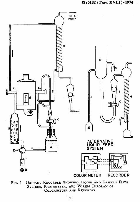
5.1 Thebpp aratus shall consist essentially of two functional parts, namely, a continu‘ous gas-liquid contacting device, and a recording calorimeter as illustrated in Fig. 1.
5.1.1 Liquid System -The liquid system shall consist of a 4-litre bottle A from which the reagent solution is forced by a constant-delivery pump B, C, D, through a bed of 2.36 mm to 850 micron activated carbon E to the top of the scrubbing column H. ‘It is optional whether or not the solution passes through a reference calorimeter cell R attached to the light source G. The solution shall then flow down over the inside wall of the glass tube H having a 6-mm inside diameter and 500 to 600 mM long. A 6-pitch spiral of l-mm glass rod shall fit snugly against this wall increasing the area of the absorbing surface, and assuring that this surface is completely and continuously wetted.
5.1.1.1 An alternative method of dispensing the absorbent to glass tube H is illustrated in the insert in Fig. I. An excess of liquid shall be delivered to the constant-level reservoir R, the excess returning to the supply bottle through the overflow S. Constant delivery tb glass tube H shall be accomplished by means of the stopcock X and the rotameter Tz.
*Glossary of terms relating to air pollution.
4
IS:5182 (Part XVIII)-1974
d?- ’ l.0 CL- K
/
1’1
ALTERNATIVE LIQUID FEED SYSTEM
COLORIMETER
__- N --- --_ m Q p
RE
FIG. 1 OXIDANT RECORDER SHOWING LIQUID AND GASEOUS FLOW SYSTEMS, PHOTOMETER, AND WIRING DIAGRAM OF
COLORIMETER AND RECORDER
5
IS : 5182 (Fart XVIII) - 1974
5.1.2 The air sample shall be\drawn through the rotameter Tr into the bottom of the absorber column IS by a pump connected to the top of the column. A surge jar prevents accidental entry of the scrubbing solution into the air pump. The solution is thus contacted countercurrently by the air sample. The air flow shall be regulated by an adjusting valve on a by-pass to the pump and also by a needle valve in-the main air stream. Alternatively, a reliable gear pump may be employed that gives excellent control of the air stream when properly oiled. From the absorber the solution flows by gravity through the measuring cell Fr of the recording calorimeter. It then returns to the storage bottle through pipette J and stopcock K which permit periodic measurement of the liquid, flow rate when stopcock X is temporarily closed. J shall bc noted.
The time required to fill pipette
NOTE - Glass should he used for all sampling lines, both gas and liquid. Spherical glass joints or TFE-fluorocarbon connectors are preferred, but vinyl sleeves on butt joints are permissible.
5.1.3 Recording $blorimeter - The recordizg calorimeter shall be
operated at 3600 A with a bandpass of 400 A, obtained by passing the light from a medium pressure mercury vapour lamp, through one or two ultraviolet filters. Alternatively, an incandescent lamp can be used. When operated at 7.5 V this lamp has a life of 10 000 hours, but has only 700 hours at 8*,5 V, if more ultraviolet light is required to operate the recorder. Figure 1 shows the wiring diagram of a calorimeter usmg sele- nium photocells. The lamps, photocells, and recorder are matched so that there is less than 0.5 percent dead band on the recorder. The drift of the calorimeter-recorder system is less than 2 percent in 24 hours with the optical cells dry or removed. There should be provision for adjusting the zero ( matched light beam ) signal level by f30 percent. There may also be provision for adjusting the infinity end of the scale to enable a close match to the calibration data. 3 cm is permissible.
Optical cell length between 1 and The cells are designed so that bubbles cannot be
trapped but quickly pass through the cells.
5.1.3.1 The recorder indicates absorbance of the solution. This
reading can be converted into concentration of iodine in the solution or directly into concentration of ozone in the atmosphere, since the air and liquid flow rates are known and constant and a stoichiometric proportion exists between ozone and iodine.
6. ABSORBENT
6.1 The absorbent shall consist of a potassium iodide ( KI) solution (2 percent ) buffered to a PH of 7 f 0’2 by adding disodium phosphate dpdecahydrate ( 3.6 percent ) and potassium dihydrogen phosphate ( 1’4 percent). The flH level shall be maintained at 7 f O-2 by adjustment with sodium hydroxide ( 1 percent) or phosphoric acid ( 1 percent) solutions. The concentration of the solution increases gradually due to
6
IS : 5182 ( Part XVIII) - 1974
evaporatiop of water; this is corrected at weekly intervals, or as necessary, by the addition of distilled water. A wide variation of the potassium iodide concentration can be tolerated.
6.2 The absorbent shall be regenerated during each pass through the system by contacting it with a bed of granular activated carbon that removes all iodine produced by the previous pass. The activated carbon will eventually be exhausted and has to be changed when the filtered solution gets appreciably yellow. A slight yellow tinge of the solution will normally be present in the storage bottle.
6.3 Zeroing is best accomplished by shutting off the air stream and operating the instrument with unaerated solutions. A .timer can be used to shut off the air stream for about 1 hour (for example, between 0400 to 0 500 h) to allow the instrument to equilibrate itself and indicate a zero level.
7. CALIBRATION 7.1 Dynamic calibration of the instrument may be performed by prepar ing a large volume of a mixture of ozone in air. For this purpose, the output of an ozonizer up to 1 to 2 ml of ozone per minute shall be fed into the intake of a small blower delivering 1000 to 2000 litres of air per minute. The gas mixtue emerges through a short length of pipe. One portion of this mixture shall be analyzed in the recorder and another aspirated through a faintly blue iodine solution containing starch (0.2 percent) and potassium iodide ( 0.1 percent). This solution shall be titrated with sodium thiosulphate ( 0.01 N or 0.001 N ) after passage of a measured volume of sample. The end point shall be established by comparison with the unaspirated faintly blue starch-iodine solution.
7.2 Mixtures of ozone and air may be prepared in polyester film bags and admitted to the analyzer through the normal satnpling circuit. The bags should have a capacity of about 100 litres. leaks and perfectly dry and clean inside.
They shall be tested for Ozone mixtures can be prepar-
ed conveniently by passing air through a tube enclosing a small mercury lamp. The concentration of ozone depends on the flow rate, the size of ballast lamp used in series with the mercury bulb, and the voltage applied. The mixtures shall be analyzed at the time they are used since the ozone decomposes gradually. The analysis can be performed by passing a measured volume through an impinger containing buffered potassium iodide.( KI) solution and determining the released iodine by titration or by a spectrometer method. With recorders that have an infinity adjustment, make the first mixture about ten times the midscale concentration and adjust the upper end of the recorder scale, having previously adjusted to zero with pure air. Make the second mixture about midscale concentration and adjust sample or reagent flow rates, or both, until the recorder reading agrees with the absorbance scale template according to the analytically determined concentration of the ozone. Check several other points on the curve if desired.
c
7
IS I 5182 ( Part XVIII ) - 1974
7.3 The calorimeter can also be calibrated by passing the absorbent to which measured concentrations of iodine have been added, through the optical cell.
7.4 The calibration chart of the instrument can be constructed from the data given in 7.1,7.2, or 7.3. Either a linear or logarithmic chart may be employed. A scale or calibration curve can be constructed to convert either chart to read in pphm. For recorders equipped with infinity adjustment, the logarithmicchart can be made to read directly in pphm by adjusting the flow rates of gas or liquid, or both, within the operation limits of the absorber.
8. PROCEDURE
8.1 Place a fresh absorbent solution in the storage bottle and operate the solution pump until the liquid lines are full. After the flow has stabilized itself, zero the recorder and start the air pump. Set the flows at convenient rates such as 4 ml/min of solution and 4 l/min of air.
8.2. Check and adjust the flow rates daily. Adjust the pH of the solution once or twice a week, at which time the solution shall be brought up to volume by addition of distilled water.
8.3 Change the carbon filter about once a,month, depending on its size and the quality of the carbon. Change the absorbing solution at the same time.
9. PRECISION
9.1 Experience has shown that different instruments of this design will agree with each other within f5 percent of the average concentration at midscale.
8
BUREAU OF INDIAN STANDARDS
Regional Offices :
Central : Manak Bhavan, 9, Bahadur Shah Zafar Marg, NEW DELHI 110002
* Eastern : 1114 C.I.T. Scheme VII M. V.I.P. Road, Maniktola, CALCUTTA 700054


![[XLS]static.springer.comstatic.springer.com/sgw/documents/1372031/application/... · Web view0 1972 1973 1973 1973 1973 1974 1974 1974 1974 1974 1974 1974 1974 1974 1974 1974 1974](https://static.documents.pub/doc/80x56/5ae3d8767f8b9a5d648e7b9b/xls-view0-1972-1973-1973-1973-1973-1974-1974-1974-1974-1974-1974-1974-1974-1974.jpg)


