Data source: DMP: 50k Surface Geology (Perth, Yanchep, Muchea); Landgate: Imagery (Virtual mosaic); GHD: Proposed Pipeline Alignment. Created by:afeeney
DRAFTPaper Size A3
999 Hay Street, Perth WA 6000 Australia T 61 8 6222 8555 F 61 8 6222 8555 E [email protected] W www.ghd.com.au
Surface Geology (50k)Bassendean Sand (S8) - SAND - very light grey at surface, yellow at depth, fine to medium-grained, sub-rounded quartz, moderately well sorted of eolian originSwamp Deposits (Cps) - PEATY CLAY dark grey and black with variable sand content, of lacustrine originSwamp Deposits (Sp) - PEATY SAND - greyish brown medium-grained quartz, moderately well sorted, variable organic content, of lacustrine originSafety Bay Sand (LS4) - LIMESTONE - pale yellowish brown, weakly cemented, friable, medium-grained, sub-rounded quartz and shell debris, of eolian origin
Safety Bay Sand (S2) - CALCAREOUS SAND - as S1Tamala Limestone (LS1) - LIMESTONE - light yellowish brown, fine to coarse-grained, sub-angular to well rounded, quartz, a trace of feldspar, shell debris, variably lithified, surface kankar of eolian originTamala Limestone (LS2) - LIMESTONE - as LS1 abundant karstic phenomena, including caves, swallows, dolinesTamala Sand (S7) - SAND - pale and olive yellow, medium to coarse-grained, sub-angular to sub-rounded quartz, trace of feldspar, moderately sorted, of residual originThin Bassendean Sand over Guildford (S10) - SAND over PEBBLY SILT - sand as S8 overlying Mgs1 gravelly silt
Water
LEGENDProposed Pipeline Alignment
Joondalup Drive
Ocean Reef Road
Title Client
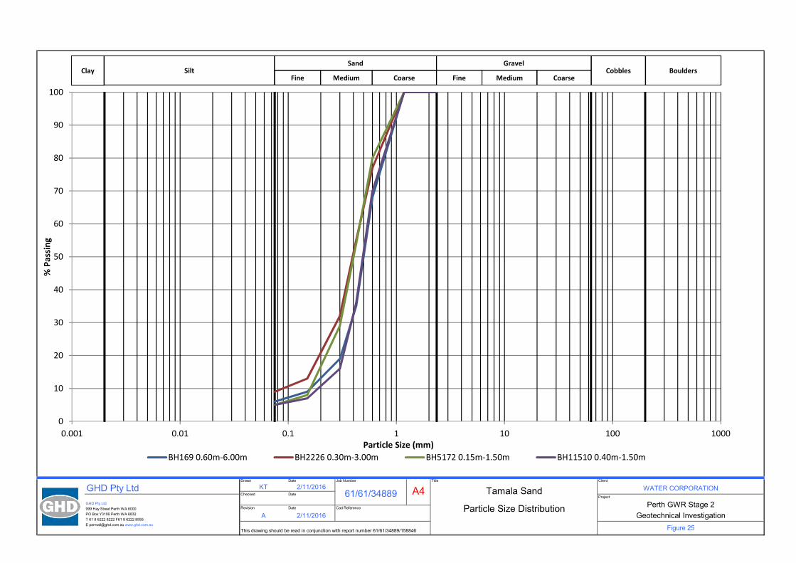
Tamala Sand WATER CORPORATIONProject
Particle Size Distribution Perth GWR Stage 2Revision Date Cad Reference
A 2/11/2016
61/61/34889
Geotechnical InvestigationFigure 25
Job Number
A4Checked DateGHD Pty Ltd
Drawn Date
KT 2/11/2016
GHD Pty Ltd999 Hay Street Perth WA 6000PO Box Y3106 Perth WA 6832T 61 8 6222 8222 F61 8 6222 8555E [email protected] www.ghd.com.au
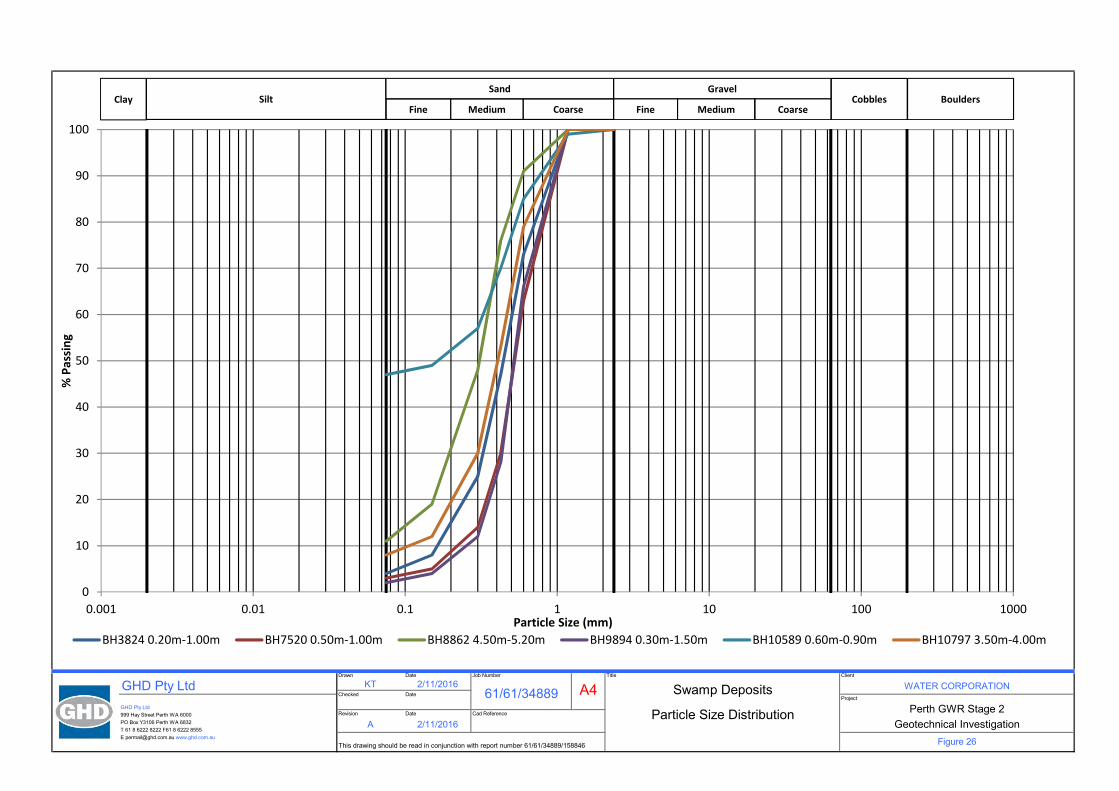
This drawing should be read in conjunction with report number 61/61/34889/158846
A4GHD Pty Ltd999 Hay Street Perth WA 6004PO Box Y3106 Perth WA 6832T 61 8 6222 8222 F61 8 6222 8555E [email protected] www.ghd.com.au
A 1/11/2016 Geotechnical Investigation
This drawing should be read in conjunction with report number 61/6134889/158846 Figure 27
Client
KT 1/11/201661/6134889 Swamp Deposits WATER CORPORATION
Checked DateProject
Title
Plasticity Chart
0
10
20
30
40
50
60
0 10 20 30 40 50 60 70 80 90 100
Plas
ticity
Inde
x (%
)
Liquid Limit (%)
BH10589 0.60-0.90m
A-Line
CL
CH
MH or OH
CL-ML
CI
ML or OL
U Line
GHD | Report for Water Corporation - Perth GWR Stage 2, 61/34889
Appendices
GHD | Report for Water Corporation - Perth GWR Stage 2, 61/34889
Appendix A – CPT Logs
LOCATION:
PROJECT:
CLIENT:
Date/s:
Job No.:
ELECTRIC FRICTION-CONE PENETROMETER
ALL DATA
Tested in accordance with AS 1289.6.5.1-1999 and IRTP 2001 for friction reducer Rig Type: 22 tonne truck (Merc)
Water Corporation
Perth GWRS Stage 2 Pipeline
Woodvale/Joondalup
61/34889
29 - 30 Sep 2016
0 5 10 15 20 25 30 35 40 45 50
00.
51
1.5
22.
53
3.5
44.
55
Tip Resistance Qt (MPa)
Dep
th (m
)
0 1 2 3 4 5 6 7 8 9 10
00.
51
1.5
22.
53
3.5
44.
55
Friction Ratio Rf (%)
Dep
th (m
)
0 50 100
150
200
250
300
350
400
450
500
00.
51
1.5
22.
53
3.5
44.
55
Friction Sleeve fs (kPa)
Dep
th (m
)
LOCATION:
PROJECT:
CLIENT:
Co-ords:
RL (m):
Job No.:
29-Sep-16
Probe I.DELECTRIC FRICTION-CONE PENETROMETER
CPTU 458
Rig Type: 22 tonne truck (Merc)Tested in accordance with AS 1289.6.5.1-1999 and IRTP 2001 for friction reducer
61/34889
Woodvale/Joondalup
Perth GWRS Stage 2 Pipeline
Water Corporation
Refusal:
Approx. Water (m): Dry to 3.2
Dummy probe to (m): File: GH1116G
Cone I.D.: EC32
0 1 2 3 4 5 6 7 8 9 10
00.
51
1.5
22.
53
3.5
44.
55
Friction Ratio Rf (%)
Dep
th (m
)
0 1 2 3 4 5 6 7 8 9 10
00.
51
1.5
22.
53
3.5
44.
55
Tip Resistance Qt (MPa)
Dep
th (m
)
0 50 100
150
200
250
300
350
400
450
500
0 5 10 15 20 25 30 35 40 45 50
00.
51
1.5
22.
53
3.5
44.
55
Friction Sleeve fs (kPa)
Tip Resistance Qt (MPa)
Dep
th (m
)
Tip
Res
ista
nce
Fric
tion
Slee
ve
LOCATION:
PROJECT:
CLIENT:
Co-ords:
RL (m):
Job No.:
29-Sep-16
Probe I.D
61/34889
File: GH1116G.txt
Approx. Water (m): Dry to 3.2Please note: Hydrostatic Line is taken from the water level manually dipped by the CPT Operator following completion of the probe and,
as such, should be used as a guide only.
ELECTRIC FRICTION-CONE PENETROMETER
Rig type: 22 tonne truck (Merc)
CPTU 458
Tested in accordance with AS 1289.6.5.1-1999 and IRTP 2001 for friction reducer
Water Corporation
Perth GWRS Stage 2 Pipeline
Woodvale/Joondalup
-40
-20
0 20 40 60 80 100
120
140
160
01
23
45
67
89
1011
1213
1415
1617
1819
20
Pw Dissipation (kPa)
Tim
e (m
in)
-20
-15
-10
-5 0 5 10 15 20
00.
51
1.5
22.
53
3.5
44.
55
Pore Pressure u2 (kPa)
Dep
th (m
)
Pore
Pre
ssur
e
Hyd
rost
atic
Pre
ssur
e
LOCATION:
PROJECT:
CLIENT:
Co-ords:
RL (m):
Job No.:
29-Sep-16
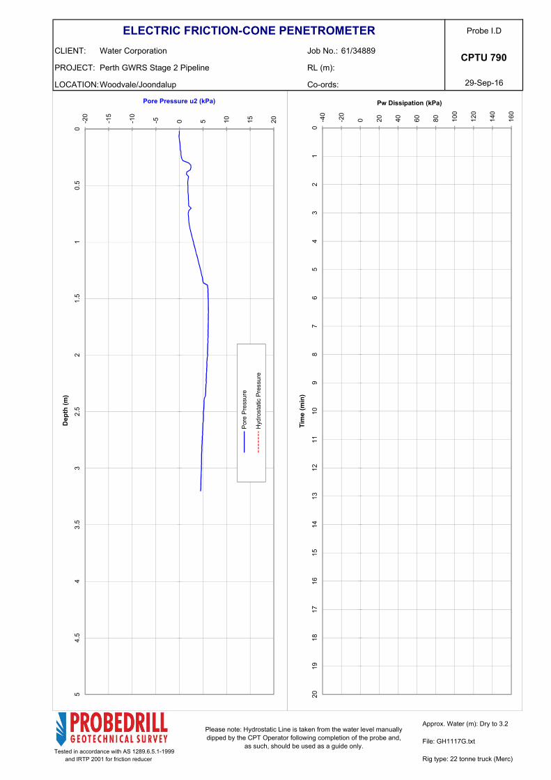
Probe I.DELECTRIC FRICTION-CONE PENETROMETER
CPTU 790
Rig Type: 22 tonne truck (Merc)Tested in accordance with AS 1289.6.5.1-1999 and IRTP 2001 for friction reducer
61/34889
Woodvale/Joondalup
Perth GWRS Stage 2 Pipeline
Water Corporation
Refusal:
Approx. Water (m): Dry to 3.2
Dummy probe to (m): 0.3 File: GH1117G
Cone I.D.: EC32
0 1 2 3 4 5 6 7 8 9 10
00.
51
1.5
22.
53
3.5
44.
55
Friction Ratio Rf (%)
Dep
th (m
)
0 1 2 3 4 5 6 7 8 9 10
00.
51
1.5
22.
53
3.5
44.
55
Tip Resistance Qt (MPa)
Dep
th (m
)
0 50 100
150
200
250
300
350
400
450
500
0 5 10 15 20 25 30 35 40 45 50
00.
51
1.5
22.
53
3.5
44.
55
Friction Sleeve fs (kPa)
Tip Resistance Qt (MPa)
Dep
th (m
)
Tip
Res
ista
nce
Fric
tion
Slee
ve
LOCATION:
PROJECT:
CLIENT:
Co-ords:
RL (m):
Job No.:
29-Sep-16
Probe I.D
61/34889
File: GH1117G.txt
Approx. Water (m): Dry to 3.2Please note: Hydrostatic Line is taken from the water level manually dipped by the CPT Operator following completion of the probe and,
as such, should be used as a guide only.
ELECTRIC FRICTION-CONE PENETROMETER
Rig type: 22 tonne truck (Merc)
CPTU 790
Tested in accordance with AS 1289.6.5.1-1999 and IRTP 2001 for friction reducer
Water Corporation
Perth GWRS Stage 2 Pipeline
Woodvale/Joondalup
-40
-20
0 20 40 60 80 100
120
140
160
01
23
45
67
89
1011
1213
1415
1617
1819
20
Pw Dissipation (kPa)
Tim
e (m
in)
-20
-15
-10
-5 0 5 10 15 20
00.
51
1.5
22.
53
3.5
44.
55
Pore Pressure u2 (kPa)
Dep
th (m
)
Pore
Pre
ssur
e
Hyd
rost
atic
Pre
ssur
e
LOCATION:
PROJECT:
CLIENT:
Co-ords:
RL (m):
Job No.:
29-Sep-16
Probe I.DELECTRIC FRICTION-CONE PENETROMETER
CPTU 1072
Rig Type: 22 tonne truck (Merc)Tested in accordance with AS 1289.6.5.1-1999 and IRTP 2001 for friction reducer
61/34889
Woodvale/Joondalup
Perth GWRS Stage 2 Pipeline
Water Corporation
Refusal:
Approx. Water (m): Dry to 3.2
Dummy probe to (m): File: GH1115G
Cone I.D.: EC32
0 1 2 3 4 5 6 7 8 9 10
00.
51
1.5
22.
53
3.5
44.
55
Friction Ratio Rf (%)
Dep
th (m
)
0 1 2 3 4 5 6 7 8 9 10
00.
51
1.5
22.
53
3.5
44.
55
Tip Resistance Qt (MPa)
Dep
th (m
)
0 50 100
150
200
250
300
350
400
450
500
0 5 10 15 20 25 30 35 40 45 50
00.
51
1.5
22.
53
3.5
44.
55
Friction Sleeve fs (kPa)
Tip Resistance Qt (MPa)
Dep
th (m
)
Tip
Res
ista
nce
Fric
tion
Slee
ve
LOCATION:
PROJECT:
CLIENT:
Co-ords:
RL (m):
Job No.:
29-Sep-16
Probe I.D
61/34889
File: GH1115G.txt
Approx. Water (m): Dry to 3.2Please note: Hydrostatic Line is taken from the water level manually dipped by the CPT Operator following completion of the probe and,
as such, should be used as a guide only.
ELECTRIC FRICTION-CONE PENETROMETER
Rig type: 22 tonne truck (Merc)
CPTU 1072
Tested in accordance with AS 1289.6.5.1-1999 and IRTP 2001 for friction reducer
Water Corporation
Perth GWRS Stage 2 Pipeline
Woodvale/Joondalup
-40
-20
0 20 40 60 80 100
120
140
160
01
23
45
67
89
1011
1213
1415
1617
1819
20
Pw Dissipation (kPa)
Tim
e (m
in)
-20
-15
-10
-5 0 5 10 15 20
00.
51
1.5
22.
53
3.5
44.
55
Pore Pressure u2 (kPa)
Dep
th (m
)
Pore
Pre
ssur
e
Hyd
rost
atic
Pre
ssur
e
LOCATION:
PROJECT:
CLIENT:
Co-ords:
RL (m):
Job No.:
29-Sep-16
Probe I.DELECTRIC FRICTION-CONE PENETROMETER
CPTU 1570
Rig Type: 22 tonne truck (Merc)Tested in accordance with AS 1289.6.5.1-1999 and IRTP 2001 for friction reducer
61/34889
Woodvale/Joondalup
Perth GWRS Stage 2 Pipeline
Water Corporation
Refusal:
Approx. Water (m): Dry to 3.2
Dummy probe to (m): 0.3 File: GH1118G
Cone I.D.: EC32
0 1 2 3 4 5 6 7 8 9 10
00.
51
1.5
22.
53
3.5
44.
55
Friction Ratio Rf (%)
Dep
th (m
)
0 1 2 3 4 5 6 7 8 9 10
00.
51
1.5
22.
53
3.5
44.
55
Tip Resistance Qt (MPa)
Dep
th (m
)
0 50 100
150
200
250
300
350
400
450
500
0 5 10 15 20 25 30 35 40 45 50
00.
51
1.5
22.
53
3.5
44.
55
Friction Sleeve fs (kPa)
Tip Resistance Qt (MPa)
Dep
th (m
)
Tip
Res
ista
nce
Fric
tion
Slee
ve
LOCATION:
PROJECT:
CLIENT:
Co-ords:
RL (m):
Job No.:
29-Sep-16
Probe I.D
61/34889
File: GH1118G.txt
Approx. Water (m): Dry to 3.2Please note: Hydrostatic Line is taken from the water level manually dipped by the CPT Operator following completion of the probe and,
as such, should be used as a guide only.
ELECTRIC FRICTION-CONE PENETROMETER
Rig type: 22 tonne truck (Merc)
CPTU 1570
Tested in accordance with AS 1289.6.5.1-1999 and IRTP 2001 for friction reducer
Water Corporation
Perth GWRS Stage 2 Pipeline
Woodvale/Joondalup
-40
-20
0 20 40 60 80 100
120
140
160
01
23
45
67
89
1011
1213
1415
1617
1819
20
Pw Dissipation (kPa)
Tim
e (m
in)
-20
-15
-10
-5 0 5 10 15 20
00.
51
1.5
22.
53
3.5
44.
55
Pore Pressure u2 (kPa)
Dep
th (m
)
Pore
Pre
ssur
e
Hyd
rost
atic
Pre
ssur
e
LOCATION:
PROJECT:
CLIENT:
Co-ords:
RL (m):
Job No.:
29-Sep-16
Probe I.DELECTRIC FRICTION-CONE PENETROMETER
CPTU 1720
Rig Type: 22 tonne truck (Merc)Tested in accordance with AS 1289.6.5.1-1999 and IRTP 2001 for friction reducer
61/34889
Woodvale/Joondalup
Perth GWRS Stage 2 Pipeline
Water Corporation
Refusal:
Approx. Water (m): Dry to 3.2
Dummy probe to (m): 0.3 File: GH1119G
Cone I.D.: EC32
0 1 2 3 4 5 6 7 8 9 10
00.
51
1.5
22.
53
3.5
44.
55
Friction Ratio Rf (%)
Dep
th (m
)
0 1 2 3 4 5 6 7 8 9 10
00.
51
1.5
22.
53
3.5
44.
55
Tip Resistance Qt (MPa)
Dep
th (m
)
0 50 100
150
200
250
300
350
400
450
500
0 5 10 15 20 25 30 35 40 45 50
00.
51
1.5
22.
53
3.5
44.
55
Friction Sleeve fs (kPa)
Tip Resistance Qt (MPa)
Dep
th (m
)
Tip
Res
ista
nce
Fric
tion
Slee
ve
LOCATION:
PROJECT:
CLIENT:
Co-ords:
RL (m):
Job No.:
29-Sep-16
Probe I.D
61/34889
File: GH1119G.txt
Approx. Water (m): Dry to 3.2Please note: Hydrostatic Line is taken from the water level manually dipped by the CPT Operator following completion of the probe and,
as such, should be used as a guide only.
ELECTRIC FRICTION-CONE PENETROMETER
Rig type: 22 tonne truck (Merc)
CPTU 1720
Tested in accordance with AS 1289.6.5.1-1999 and IRTP 2001 for friction reducer
Water Corporation
Perth GWRS Stage 2 Pipeline
Woodvale/Joondalup
-40
-20
0 20 40 60 80 100
120
140
160
01
23
45
67
89
1011
1213
1415
1617
1819
20
Pw Dissipation (kPa)
Tim
e (m
in)
-20
-15
-10
-5 0 5 10 15 20
00.
51
1.5
22.
53
3.5
44.
55
Pore Pressure u2 (kPa)
Dep
th (m
)
Pore
Pre
ssur
e
Hyd
rost
atic
Pre
ssur
e
Natasha
Typewritten Text
Natasha
Typewritten Text
LOCATION:
PROJECT:
CLIENT:
Co-ords:
RL (m):
Job No.:
29-Sep-16
Probe I.DELECTRIC FRICTION-CONE PENETROMETER
CPTU 2054
Rig Type: 22 tonne truck (Merc)Tested in accordance with AS 1289.6.5.1-1999 and IRTP 2001 for friction reducer
61/34889
Woodvale/Joondalup
Perth GWRS Stage 2 Pipeline
Water Corporation
Refusal:
Approx. Water (m): Dry to 3.2
Dummy probe to (m): 0.3 File: GH1120G
Cone I.D.: EC32
0 1 2 3 4 5 6 7 8 9 10
00.
51
1.5
22.
53
3.5
44.
55
Friction Ratio Rf (%)
Dep
th (m
)
0 1 2 3 4 5 6 7 8 9 10
00.
51
1.5
22.
53
3.5
44.
55
Tip Resistance Qt (MPa)
Dep
th (m
)
0 50 100
150
200
250
300
350
400
450
500
0 5 10 15 20 25 30 35 40 45 50
00.
51
1.5
22.
53
3.5
44.
55
Friction Sleeve fs (kPa)
Tip Resistance Qt (MPa)
Dep
th (m
)
Tip
Res
ista
nce
Fric
tion
Slee
ve
LOCATION:
PROJECT:
CLIENT:
Co-ords:
RL (m):
Job No.:
29-Sep-16
Probe I.DELECTRIC FRICTION-CONE PENETROMETER
CPTU 2054
Rig Type: 22 tonne truck (Merc)Tested in accordance with AS 1289.6.5.1-1999 and IRTP 2001 for friction reducer
61/34889
Woodvale/Joondalup
Perth GWRS Stage 2 Pipeline
Water Corporation
Refusal:
Approx. Water (m): Dry to 3.2
Dummy probe to (m): 0.3 File: GH1120G
Cone I.D.: EC32
0 1 2 3 4 5 6 7 8 9 10
00.
51
1.5
22.
53
3.5
44.
55
Friction Ratio Rf (%)
Dep
th (m
)
0 1 2 3 4 5 6 7 8 9 10
00.
51
1.5
22.
53
3.5
44.
55
Tip Resistance Qt (MPa)
Dep
th (m
)
0 50 100
150
200
250
300
350
400
450
500
550
600
0 5 10 15 20 25 30 35 40 45 50 55 60
00.
51
1.5
22.
53
3.5
44.
55
Friction Sleeve fs (kPa)
Tip Resistance Qt (MPa)
Dep
th (m
)
Tip
Res
ista
nce
Fric
tion
Slee
ve
LOCATION:
PROJECT:
CLIENT:
Co-ords:
RL (m):
Job No.:
29-Sep-16
Probe I.D
61/34889
File: GH1120G.txt
Approx. Water (m): Dry to 3.2Please note: Hydrostatic Line is taken from the water level manually dipped by the CPT Operator following completion of the probe and,
as such, should be used as a guide only.
ELECTRIC FRICTION-CONE PENETROMETER
Rig type: 22 tonne truck (Merc)
CPTU 2054
Tested in accordance with AS 1289.6.5.1-1999 and IRTP 2001 for friction reducer
Water Corporation
Perth GWRS Stage 2 Pipeline
Woodvale/Joondalup
-40
-20
0 20 40 60 80 100
120
140
160
01
23
45
67
89
1011
1213
1415
1617
1819
20
Pw Dissipation (kPa)
Tim
e (m
in)
-20
-15
-10
-5 0 5 10 15 20
00.
51
1.5
22.
53
3.5
44.
55
Pore Pressure u2 (kPa)
Dep
th (m
)
Pore
Pre
ssur
e
Hyd
rost
atic
Pre
ssur
e
LOCATION:
PROJECT:
CLIENT:
Co-ords:
RL (m):
Job No.:
29-Sep-16
Probe I.DELECTRIC FRICTION-CONE PENETROMETER
CPTU 2374
Rig Type: 22 tonne truck (Merc)Tested in accordance with AS 1289.6.5.1-1999 and IRTP 2001 for friction reducer
61/34889
Woodvale/Joondalup
Perth GWRS Stage 2 Pipeline
Water Corporation
Refusal:
Approx. Water (m): Dry to 3.2
Dummy probe to (m): File: GH1121G
Cone I.D.: EC32
0 1 2 3 4 5 6 7 8 9 10
00.
51
1.5
22.
53
3.5
44.
55
Friction Ratio Rf (%)
Dep
th (m
)
0 1 2 3 4 5 6 7 8 9 10
00.
51
1.5
22.
53
3.5
44.
55
Tip Resistance Qt (MPa)
Dep
th (m
)
0 50 100
150
200
250
300
350
400
450
500
0 5 10 15 20 25 30 35 40 45 50
00.
51
1.5
22.
53
3.5
44.
55
Friction Sleeve fs (kPa)
Tip Resistance Qt (MPa)
Dep
th (m
)
Tip
Res
ista
nce
Fric
tion
Slee
ve
LOCATION:
PROJECT:
CLIENT:
Co-ords:
RL (m):
Job No.:
29-Sep-16
Probe I.D
61/34889
File: GH1121G.txt
Approx. Water (m): Dry to 3.2Please note: Hydrostatic Line is taken from the water level manually dipped by the CPT Operator following completion of the probe and,
as such, should be used as a guide only.
ELECTRIC FRICTION-CONE PENETROMETER
Rig type: 22 tonne truck (Merc)
CPTU 2374
Tested in accordance with AS 1289.6.5.1-1999 and IRTP 2001 for friction reducer
Water Corporation
Perth GWRS Stage 2 Pipeline
Woodvale/Joondalup
-40
-20
0 20 40 60 80 100
120
140
160
01
23
45
67
89
1011
1213
1415
1617
1819
20
Pw Dissipation (kPa)
Tim
e (m
in)
-20
-15
-10
-5 0 5 10 15 20
00.
51
1.5
22.
53
3.5
44.
55
Pore Pressure u2 (kPa)
Dep
th (m
)
Pore
Pre
ssur
e
Hyd
rost
atic
Pre
ssur
e
LOCATION:
PROJECT:
CLIENT:
Co-ords:
RL (m):
Job No.:
29-Sep-16
Probe I.DELECTRIC FRICTION-CONE PENETROMETER
CPTU 2701
Rig Type: 22 tonne truck (Merc)Tested in accordance with AS 1289.6.5.1-1999 and IRTP 2001 for friction reducer
61/34889
Woodvale/Joondalup
Perth GWRS Stage 2 Pipeline
Water Corporation
Refusal:
Approx. Water (m): 0.3
Dummy probe to (m): File: GH1122G
Cone I.D.: EC32
0 1 2 3 4 5 6 7 8 9 10
00.
51
1.5
22.
53
3.5
44.
55
Friction Ratio Rf (%)
Dep
th (m
)
0 1 2 3 4 5 6 7 8 9 10
00.
51
1.5
22.
53
3.5
44.
55
Tip Resistance Qt (MPa)
Dep
th (m
)
0 50 100
150
200
250
300
350
400
450
500
0 5 10 15 20 25 30 35 40 45 50
00.
51
1.5
22.
53
3.5
44.
55
Friction Sleeve fs (kPa)
Tip Resistance Qt (MPa)
Dep
th (m
)
Tip
Res
ista
nce
Fric
tion
Slee
ve
LOCATION:
PROJECT:
CLIENT:
Co-ords:
RL (m):
Job No.:
29-Sep-16
Probe I.DELECTRIC FRICTION-CONE PENETROMETER
Rig type: 22 tonne truck (Merc)
CPTU 2701
Tested in accordance with AS 1289.6.5.1-1999 and IRTP 2001 for friction reducer
Water Corporation
Perth GWRS Stage 2 Pipeline
Woodvale/Joondalup
61/34889
File: GH1122G.txt
Approx. Water (m): 0.3Please note: Hydrostatic Line is taken from the water level manually dipped by the CPT Operator following completion of the probe and,
as such, should be used as a guide only.
-40
-20
0 20 40 60 80 100
120
140
160
01
23
45
67
89
1011
1213
1415
1617
1819
20
Pw Dissipation (kPa)
Tim
e (m
in)
-100
-90
-80
-70
-60
-50
-40
-30
-20
-10
0 10 20 30 40 50
00.
51
1.5
22.
53
3.5
44.
55
Pore Pressure u2 (kPa)
Dep
th (m
)
Pore
Pre
ssur
e
Hyd
rost
atic
Pre
ssur
e
LOCATION:
PROJECT:
CLIENT:
Co-ords:
RL (m):
Job No.:
29-Sep-16
Probe I.DELECTRIC FRICTION-CONE PENETROMETER
CPTU 3026
Rig Type: 22 tonne truck (Merc)Tested in accordance with AS 1289.6.5.1-1999 and IRTP 2001 for friction reducer
61/34889
Woodvale/Joondalup
Perth GWRS Stage 2 Pipeline
Water Corporation
Refusal:
Approx. Water (m): Dry to 3.2
Dummy probe to (m): File: GH1123G
Cone I.D.: EC32
0 1 2 3 4 5 6 7 8 9 10
00.
51
1.5
22.
53
3.5
44.
55
Friction Ratio Rf (%)
Dep
th (m
)
0 1 2 3 4 5 6 7 8 9 10
00.
51
1.5
22.
53
3.5
44.
55
Tip Resistance Qt (MPa)
Dep
th (m
)
0 50 100
150
200
250
300
350
400
450
500
0 5 10 15 20 25 30 35 40 45 50
00.
51
1.5
22.
53
3.5
44.
55
Friction Sleeve fs (kPa)
Tip Resistance Qt (MPa)
Dep
th (m
)
Tip
Res
ista
nce
Fric
tion
Slee
ve
LOCATION:
PROJECT:
CLIENT:
Co-ords:
RL (m):
Job No.:
29-Sep-16
Probe I.DELECTRIC FRICTION-CONE PENETROMETER
Rig type: 22 tonne truck (Merc)
CPTU 3026
Tested in accordance with AS 1289.6.5.1-1999 and IRTP 2001 for friction reducer
Water Corporation
Perth GWRS Stage 2 Pipeline
Woodvale/Joondalup
61/34889
File: GH1123G.txt
Approx. Water (m): Dry to 3.2Please note: Hydrostatic Line is taken from the water level manually dipped by the CPT Operator following completion of the probe and,
as such, should be used as a guide only.
-40
-20
0 20 40 60 80 100
120
140
160
01
23
45
67
89
1011
1213
1415
1617
1819
20
Pw Dissipation (kPa)
Tim
e (m
in)
-20
-15
-10
-5 0 5 10 15 20
00.
51
1.5
22.
53
3.5
44.
55
Pore Pressure u2 (kPa)
Dep
th (m
)
Pore
Pre
ssur
e
Hyd
rost
atic
Pre
ssur
e
LOCATION:
PROJECT:
CLIENT:
Co-ords:
RL (m):
Job No.:
29-Sep-16
Probe I.DELECTRIC FRICTION-CONE PENETROMETER
CPTU 3338
Rig Type: 22 tonne truck (Merc)Tested in accordance with AS 1289.6.5.1-1999 and IRTP 2001 for friction reducer
61/34889
Woodvale/Joondalup
Perth GWRS Stage 2 Pipeline
Water Corporation
Refusal:
Approx. Water (m): 0.6
Dummy probe to (m): File: GH1124G
Cone I.D.: EC32
0 1 2 3 4 5 6 7 8 9 10
00.
51
1.5
22.
53
3.5
44.
55
Friction Ratio Rf (%)
Dep
th (m
)
0 1 2 3 4 5 6 7 8 9 10
00.
51
1.5
22.
53
3.5
44.
55
Tip Resistance Qt (MPa)
Dep
th (m
)
0 50 100
150
200
250
300
350
400
450
500
0 5 10 15 20 25 30 35 40 45 50
00.
51
1.5
22.
53
3.5
44.
55
Friction Sleeve fs (kPa)
Tip Resistance Qt (MPa)
Dep
th (m
)
Tip
Res
ista
nce
Fric
tion
Slee
ve
LOCATION:
PROJECT:
CLIENT:
Co-ords:
RL (m):
Job No.:
29-Sep-16
Probe I.D
Approx. Water (m): 0.6Please note: Hydrostatic Line is taken from the water level manually dipped by the CPT Operator following completion of the probe and,
as such, should be used as a guide only.
ELECTRIC FRICTION-CONE PENETROMETER
Rig type: 22 tonne truck (Merc)
CPTU 3338
Tested in accordance with AS 1289.6.5.1-1999 and IRTP 2001 for friction reducer
Water Corporation
Perth GWRS Stage 2 Pipeline
Woodvale/Joondalup
61/34889
File: GH1124G.txt
-40
-20
0 20 40 60 80 100
120
140
160
01
23
45
67
89
1011
1213
1415
1617
1819
20
Pw Dissipation (kPa)
Tim
e (m
in)
-100
-90
-80
-70
-60
-50
-40
-30
-20
-10
0 10 20 30 40 50
00.
51
1.5
22.
53
3.5
44.
55
Pore Pressure u2 (kPa)
Dep
th (m
)
Pore
Pre
ssur
e
Hyd
rost
atic
Pre
ssur
e
LOCATION:
PROJECT:
CLIENT:
Co-ords:
RL (m):
Job No.:
29-Sep-16
Probe I.DELECTRIC FRICTION-CONE PENETROMETER
CPTU 3654
Rig Type: 22 tonne truck (Merc)Tested in accordance with AS 1289.6.5.1-1999 and IRTP 2001 for friction reducer
61/34889
Woodvale/Joondalup
Perth GWRS Stage 2 Pipeline
Water Corporation
Refusal:
Approx. Water (m): Dry to 1.6
Dummy probe to (m): File: GH1125G
Cone I.D.: EC32
0 1 2 3 4 5 6 7 8 9 10
00.
51
1.5
22.
53
3.5
44.
55
Friction Ratio Rf (%)
Dep
th (m
)
0 1 2 3 4 5 6 7 8 9 10
00.
51
1.5
22.
53
3.5
44.
55
Tip Resistance Qt (MPa)
Dep
th (m
)
0 50 100
150
200
250
300
350
400
450
500
0 5 10 15 20 25 30 35 40 45 50
00.
51
1.5
22.
53
3.5
44.
55
Friction Sleeve fs (kPa)
Tip Resistance Qt (MPa)
Dep
th (m
)
Tip
Res
ista
nce
Fric
tion
Slee
ve
LOCATION:
PROJECT:
CLIENT:
Co-ords:
RL (m):
Job No.:
29-Sep-16
Probe I.D
Approx. Water (m): Dry to 1.6Please note: Hydrostatic Line is taken from the water level manually dipped by the CPT Operator following completion of the probe and,
as such, should be used as a guide only.
ELECTRIC FRICTION-CONE PENETROMETER
Rig type: 22 tonne truck (Merc)
CPTU 3654
Tested in accordance with AS 1289.6.5.1-1999 and IRTP 2001 for friction reducer
Water Corporation
Perth GWRS Stage 2 Pipeline
Woodvale/Joondalup
61/34889
File: GH1125G.txt
-40
-20
0 20 40 60 80 100
120
140
160
01
23
45
67
89
1011
1213
1415
1617
1819
20
Pw Dissipation (kPa)
Tim
e (m
in)
-50
-40
-30
-20
-10
0 10 20 30 40 50
00.
51
1.5
22.
53
3.5
44.
55
Pore Pressure u2 (kPa)
Dep
th (m
)
Pore
Pre
ssur
e
Hyd
rost
atic
Pre
ssur
e
LOCATION:
PROJECT:
CLIENT:
Co-ords:
RL (m):
Job No.:
29-Sep-16
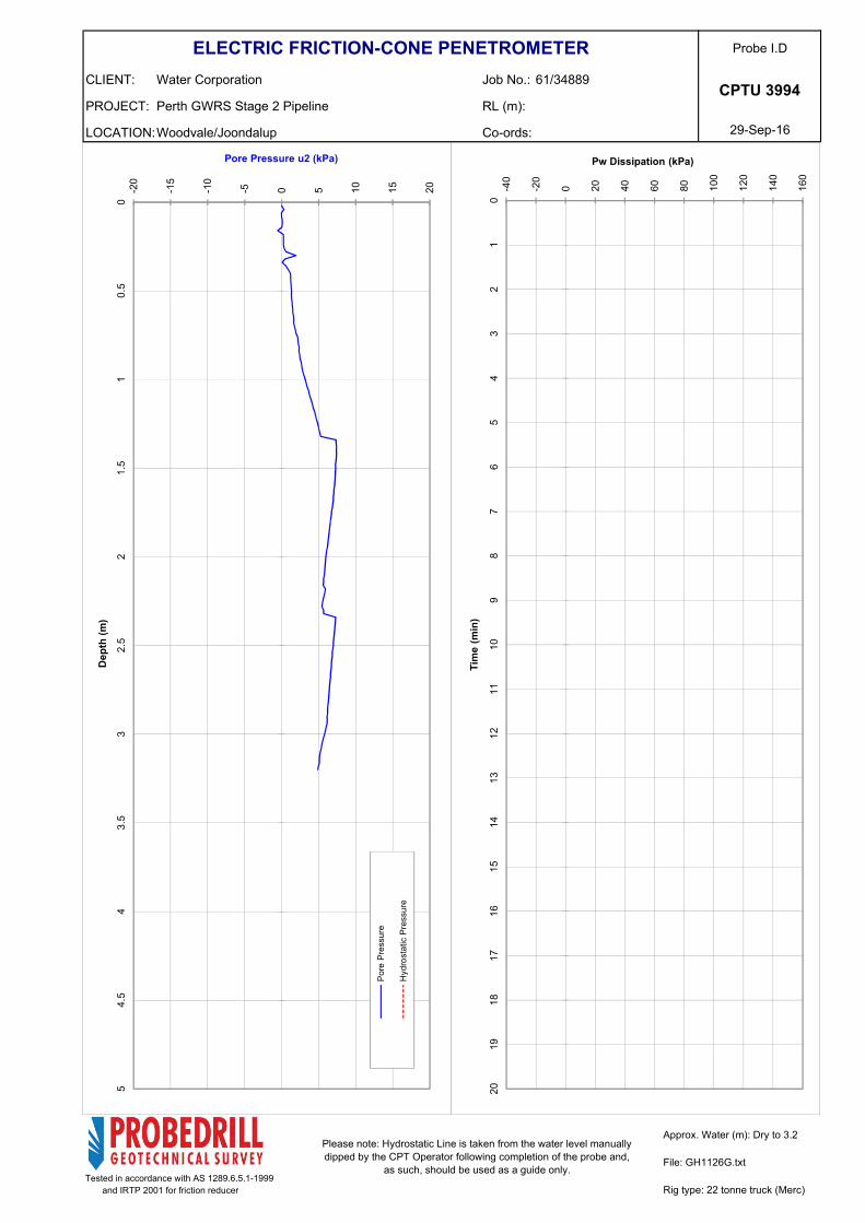
Probe I.DELECTRIC FRICTION-CONE PENETROMETER
CPTU 3994
Rig Type: 22 tonne truck (Merc)Tested in accordance with AS 1289.6.5.1-1999 and IRTP 2001 for friction reducer
61/34889
Woodvale/Joondalup
Perth GWRS Stage 2 Pipeline
Water Corporation
Refusal:
Approx. Water (m): Dry to 3.2
Dummy probe to (m): File: GH1126G
Cone I.D.: EC32
0 1 2 3 4 5 6 7 8 9 10
00.
51
1.5
22.
53
3.5
44.
55
Friction Ratio Rf (%)
Dep
th (m
)
0 1 2 3 4 5 6 7 8 9 10
00.
51
1.5
22.
53
3.5
44.
55
Tip Resistance Qt (MPa)
Dep
th (m
)
0 50 100
150
200
250
300
350
400
450
500
0 5 10 15 20 25 30 35 40 45 50
00.
51
1.5
22.
53
3.5
44.
55
Friction Sleeve fs (kPa)
Tip Resistance Qt (MPa)
Dep
th (m
)
Tip
Res
ista
nce
Fric
tion
Slee
ve
LOCATION:
PROJECT:
CLIENT:
Co-ords:
RL (m):
Job No.:
29-Sep-16
Probe I.D
Approx. Water (m): Dry to 3.2Please note: Hydrostatic Line is taken from the water level manually dipped by the CPT Operator following completion of the probe and,
as such, should be used as a guide only.
ELECTRIC FRICTION-CONE PENETROMETER
Rig type: 22 tonne truck (Merc)
CPTU 3994
Tested in accordance with AS 1289.6.5.1-1999 and IRTP 2001 for friction reducer
Water Corporation
Perth GWRS Stage 2 Pipeline
Woodvale/Joondalup
61/34889
File: GH1126G.txt
-40
-20
0 20 40 60 80 100
120
140
160
01
23
45
67
89
1011
1213
1415
1617
1819
20
Pw Dissipation (kPa)
Tim
e (m
in)
-20
-15
-10
-5 0 5 10 15 20
00.
51
1.5
22.
53
3.5
44.
55
Pore Pressure u2 (kPa)
Dep
th (m
)
Pore
Pre
ssur
e
Hyd
rost
atic
Pre
ssur
e
LOCATION:
PROJECT:
CLIENT:
Co-ords:
RL (m):
Job No.:
29-Sep-16
Probe I.DELECTRIC FRICTION-CONE PENETROMETER
CPTU 4337
Rig Type: 22 tonne truck (Merc)Tested in accordance with AS 1289.6.5.1-1999 and IRTP 2001 for friction reducer
61/34889
Woodvale/Joondalup
Perth GWRS Stage 2 Pipeline
Water Corporation
Refusal:
Approx. Water (m): Dry to 3.2
Dummy probe to (m): File: GH1127G
Cone I.D.: EC32
0 1 2 3 4 5 6 7 8 9 10
00.
51
1.5
22.
53
3.5
44.
55
Friction Ratio Rf (%)
Dep
th (m
)
0 1 2 3 4 5 6 7 8 9 10
00.
51
1.5
22.
53
3.5
44.
55
Tip Resistance Qt (MPa)
Dep
th (m
)
0 50 100
150
200
250
300
350
400
450
500
0 5 10 15 20 25 30 35 40 45 50
00.
51
1.5
22.
53
3.5
44.
55
Friction Sleeve fs (kPa)
Tip Resistance Qt (MPa)
Dep
th (m
)
Tip
Res
ista
nce
Fric
tion
Slee
ve
LOCATION:
PROJECT:
CLIENT:
Co-ords:
RL (m):
Job No.:
29-Sep-16
Probe I.D
Approx. Water (m): Dry to 3.2Please note: Hydrostatic Line is taken from the water level manually dipped by the CPT Operator following completion of the probe and,
as such, should be used as a guide only.
ELECTRIC FRICTION-CONE PENETROMETER
Rig type: 22 tonne truck (Merc)
CPTU 4337
Tested in accordance with AS 1289.6.5.1-1999 and IRTP 2001 for friction reducer
Water Corporation
Perth GWRS Stage 2 Pipeline
Woodvale/Joondalup
61/34889
File: GH1127G.txt
-40
-20
0 20 40 60 80 100
120
140
160
01
23
45
67
89
1011
1213
1415
1617
1819
20
Pw Dissipation (kPa)
Tim
e (m
in)
-20
-15
-10
-5 0 5 10 15 20
00.
51
1.5
22.
53
3.5
44.
55
Pore Pressure u2 (kPa)
Dep
th (m
)
Pore
Pre
ssur
e
Hyd
rost
atic
Pre
ssur
e
LOCATION:
PROJECT:
CLIENT:
Co-ords:
RL (m):
Job No.:
29-Sep-16
Probe I.DELECTRIC FRICTION-CONE PENETROMETER
CPTU 4665
Rig Type: 22 tonne truck (Merc)Tested in accordance with AS 1289.6.5.1-1999 and IRTP 2001 for friction reducer
61/34889
Woodvale/Joondalup
Perth GWRS Stage 2 Pipeline
Water Corporation
Refusal:
Approx. Water (m): Dry to 3.2
Dummy probe to (m): File: GH1128G
Cone I.D.: EC32
0 1 2 3 4 5 6 7 8 9 10
00.
51
1.5
22.
53
3.5
44.
55
Friction Ratio Rf (%)
Dep
th (m
)
0 1 2 3 4 5 6 7 8 9 10
00.
51
1.5
22.
53
3.5
44.
55
Tip Resistance Qt (MPa)
Dep
th (m
)
0 50 100
150
200
250
300
350
400
450
500
0 5 10 15 20 25 30 35 40 45 50
00.
51
1.5
22.
53
3.5
44.
55
Friction Sleeve fs (kPa)
Tip Resistance Qt (MPa)
Dep
th (m
)
Tip
Res
ista
nce
Fric
tion
Slee
ve
LOCATION:
PROJECT:
CLIENT:
Co-ords:
RL (m):
Job No.:
29-Sep-16
Probe I.D
Approx. Water (m): Dry to 3.2Please note: Hydrostatic Line is taken from the water level manually dipped by the CPT Operator following completion of the probe and,
as such, should be used as a guide only.
ELECTRIC FRICTION-CONE PENETROMETER
Rig type: 22 tonne truck (Merc)
CPTU 4665
Tested in accordance with AS 1289.6.5.1-1999 and IRTP 2001 for friction reducer
Water Corporation
Perth GWRS Stage 2 Pipeline
Woodvale/Joondalup
61/34889
File: GH1128G.txt
-40
-20
0 20 40 60 80 100
120
140
160
01
23
45
67
89
1011
1213
1415
1617
1819
20
Pw Dissipation (kPa)
Tim
e (m
in)
-20
-15
-10
-5 0 5 10 15 20
00.
51
1.5
22.
53
3.5
44.
55
Pore Pressure u2 (kPa)
Dep
th (m
)
Pore
Pre
ssur
e
Hyd
rost
atic
Pre
ssur
e
LOCATION:
PROJECT:
CLIENT:
Co-ords:
RL (m):
Job No.:
29-Sep-16
Probe I.DELECTRIC FRICTION-CONE PENETROMETER
CPTU 4999
Rig Type: 22 tonne truck (Merc)Tested in accordance with AS 1289.6.5.1-1999 and IRTP 2001 for friction reducer
61/34889
Woodvale/Joondalup
Perth GWRS Stage 2 Pipeline
Water Corporation
Refusal:
Approx. Water (m): Dry to 3.2
Dummy probe to (m): File: GH1129G
Cone I.D.: EC32
0 1 2 3 4 5 6 7 8 9 10
00.
51
1.5
22.
53
3.5
44.
55
Friction Ratio Rf (%)
Dep
th (m
)
0 1 2 3 4 5 6 7 8 9 10
00.
51
1.5
22.
53
3.5
44.
55
Tip Resistance Qt (MPa)
Dep
th (m
)
0 50 100
150
200
250
300
350
400
450
500
0 5 10 15 20 25 30 35 40 45 50
00.
51
1.5
22.
53
3.5
44.
55
Friction Sleeve fs (kPa)
Tip Resistance Qt (MPa)
Dep
th (m
)
Tip
Res
ista
nce
Fric
tion
Slee
ve
LOCATION:
PROJECT:
CLIENT:
Co-ords:
RL (m):
Job No.:
29-Sep-16
Probe I.D
Approx. Water (m): Dry to 3.2Please note: Hydrostatic Line is taken from the water level manually dipped by the CPT Operator following completion of the probe and,
as such, should be used as a guide only.
ELECTRIC FRICTION-CONE PENETROMETER
Rig type: 22 tonne truck (Merc)
CPTU 4999
Tested in accordance with AS 1289.6.5.1-1999 and IRTP 2001 for friction reducer
Water Corporation
Perth GWRS Stage 2 Pipeline
Woodvale/Joondalup
61/34889
File: GH1129G.txt
-40
-20
0 20 40 60 80 100
120
140
160
01
23
45
67
89
1011
1213
1415
1617
1819
20
Pw Dissipation (kPa)
Tim
e (m
in)
-20
-15
-10
-5 0 5 10 15 20
00.
51
1.5
22.
53
3.5
44.
55
Pore Pressure u2 (kPa)
Dep
th (m
)
Pore
Pre
ssur
e
Hyd
rost
atic
Pre
ssur
e
LOCATION:
PROJECT:
CLIENT:
Co-ords:
RL (m):
Job No.:
29-Sep-16
Probe I.DELECTRIC FRICTION-CONE PENETROMETER
CPTU 5342
Rig Type: 22 tonne truck (Merc)Tested in accordance with AS 1289.6.5.1-1999 and IRTP 2001 for friction reducer
61/34889
Woodvale/Joondalup
Perth GWRS Stage 2 Pipeline
Water Corporation
Refusal:
Approx. Water (m): 2.5
Dummy probe to (m): File: GH1130G
Cone I.D.: EC32
0 1 2 3 4 5 6 7 8 9 10
00.
51
1.5
22.
53
3.5
44.
55
Friction Ratio Rf (%)
Dep
th (m
)
0 1 2 3 4 5 6 7 8 9 10
00.
51
1.5
22.
53
3.5
44.
55
Tip Resistance Qt (MPa)
Dep
th (m
)
0 50 100
150
200
250
300
350
400
450
500
0 5 10 15 20 25 30 35 40 45 50
00.
51
1.5
22.
53
3.5
44.
55
Friction Sleeve fs (kPa)
Tip Resistance Qt (MPa)
Dep
th (m
)
Tip
Res
ista
nce
Fric
tion
Slee
ve
LOCATION:
PROJECT:
CLIENT:
Co-ords:
RL (m):
Job No.:
29-Sep-16
Probe I.D
Approx. Water (m): 2.5Please note: Hydrostatic Line is taken from the water level manually dipped by the CPT Operator following completion of the probe and,
as such, should be used as a guide only.
ELECTRIC FRICTION-CONE PENETROMETER
Rig type: 22 tonne truck (Merc)
CPTU 5342
Tested in accordance with AS 1289.6.5.1-1999 and IRTP 2001 for friction reducer
Water Corporation
Perth GWRS Stage 2 Pipeline
Woodvale/Joondalup
61/34889
File: GH1130G.txt
-40
-20
0 20 40 60 80 100
120
140
160
01
23
45
67
89
1011
1213
1415
1617
1819
20
Pw Dissipation (kPa)
Tim
e (m
in)
-20
-15
-10
-5 0 5 10 15 20
00.
51
1.5
22.
53
3.5
44.
55
Pore Pressure u2 (kPa)
Dep
th (m
)
Pore
Pre
ssur
e
Hyd
rost
atic
Pre
ssur
e
LOCATION:
PROJECT:
CLIENT:
Co-ords:
RL (m):
Job No.:
29-Sep-16
Probe I.DELECTRIC FRICTION-CONE PENETROMETER
CPTU 5668
Rig Type: 22 tonne truck (Merc)Tested in accordance with AS 1289.6.5.1-1999 and IRTP 2001 for friction reducer
61/34889
Woodvale/Joondalup
Perth GWRS Stage 2 Pipeline
Water Corporation
Refusal:
Approx. Water (m): 1.9
Dummy probe to (m): File: GH1131G
Cone I.D.: EC32
0 1 2 3 4 5 6 7 8 9 10
00.
51
1.5
22.
53
3.5
44.
55
Friction Ratio Rf (%)
Dep
th (m
)
0 1 2 3 4 5 6 7 8 9 10
00.
51
1.5
22.
53
3.5
44.
55
Tip Resistance Qt (MPa)
Dep
th (m
)
0 50 100
150
200
250
300
350
400
450
500
0 5 10 15 20 25 30 35 40 45 50
00.
51
1.5
22.
53
3.5
44.
55
Friction Sleeve fs (kPa)
Tip Resistance Qt (MPa)
Dep
th (m
)
Tip
Res
ista
nce
Fric
tion
Slee
ve
LOCATION:
PROJECT:
CLIENT:
Co-ords:
RL (m):
Job No.:
29-Sep-16
Probe I.D
Approx. Water (m): 1.9Please note: Hydrostatic Line is taken from the water level manually dipped by the CPT Operator following completion of the probe and,
as such, should be used as a guide only.
ELECTRIC FRICTION-CONE PENETROMETER
Rig type: 22 tonne truck (Merc)
CPTU 5668
Tested in accordance with AS 1289.6.5.1-1999 and IRTP 2001 for friction reducer
Water Corporation
Perth GWRS Stage 2 Pipeline
Woodvale/Joondalup
61/34889
File: GH1131G.txt
-40
-20
0 20 40 60 80 100
120
140
160
01
23
45
67
89
1011
1213
1415
1617
1819
20
Pw Dissipation (kPa)
Tim
e (m
in)
-20
-15
-10
-5 0 5 10 15 20
00.
51
1.5
22.
53
3.5
44.
55
Pore Pressure u2 (kPa)
Dep
th (m
)
Pore
Pre
ssur
e
Hyd
rost
atic
Pre
ssur
e
LOCATION:
PROJECT:
CLIENT:
Co-ords:
RL (m):
Job No.:
29-Sep-16
Probe I.DELECTRIC FRICTION-CONE PENETROMETER
CPTU 6007
Rig Type: 22 tonne truck (Merc)Tested in accordance with AS 1289.6.5.1-1999 and IRTP 2001 for friction reducer
61/34889
Woodvale/Joondalup
Perth GWRS Stage 2 Pipeline
Water Corporation
Refusal:
Approx. Water (m): Dry to 3.2
Dummy probe to (m): File: GH1132G
Cone I.D.: EC32
0 1 2 3 4 5 6 7 8 9 10
00.
51
1.5
22.
53
3.5
44.
55
Friction Ratio Rf (%)
Dep
th (m
)
0 1 2 3 4 5 6 7 8 9 10
00.
51
1.5
22.
53
3.5
44.
55
Tip Resistance Qt (MPa)
Dep
th (m
)
0 50 100
150
200
250
300
350
400
450
500
0 5 10 15 20 25 30 35 40 45 50
00.
51
1.5
22.
53
3.5
44.
55
Friction Sleeve fs (kPa)
Tip Resistance Qt (MPa)
Dep
th (m
)
Tip
Res
ista
nce
Fric
tion
Slee
ve
LOCATION:
PROJECT:
CLIENT:
Co-ords:
RL (m):
Job No.:
29-Sep-16
Probe I.D
Approx. Water (m): Dry to 3.2Please note: Hydrostatic Line is taken from the water level manually dipped by the CPT Operator following completion of the probe and,
as such, should be used as a guide only.
ELECTRIC FRICTION-CONE PENETROMETER
Rig type: 22 tonne truck (Merc)
CPTU 6007
Tested in accordance with AS 1289.6.5.1-1999 and IRTP 2001 for friction reducer
Water Corporation
Perth GWRS Stage 2 Pipeline
Woodvale/Joondalup
61/34889
File: GH1132G.txt
-40
-20
0 20 40 60 80 100
120
140
160
01
23
45
67
89
1011
1213
1415
1617
1819
20
Pw Dissipation (kPa)
Tim
e (m
in)
-20
-15
-10
-5 0 5 10 15 20
00.
51
1.5
22.
53
3.5
44.
55
Pore Pressure u2 (kPa)
Dep
th (m
)
Pore
Pre
ssur
e
Hyd
rost
atic
Pre
ssur
e
LOCATION:
PROJECT:
CLIENT:
Co-ords:
RL (m):
Job No.:
30-Sep-16
Probe I.DELECTRIC FRICTION-CONE PENETROMETER
CPTU 6346
Rig Type: 22 tonne truck (Merc)Tested in accordance with AS 1289.6.5.1-1999 and IRTP 2001 for friction reducer
61/34889
Woodvale/Joondalup
Perth GWRS Stage 2 Pipeline
Water Corporation
Refusal:
Approx. Water (m): 1.5
Dummy probe to (m): File: GH1140G
Cone I.D.: EC32
0 1 2 3 4 5 6 7 8 9 10
00.
51
1.5
22.
53
3.5
44.
55
Friction Ratio Rf (%)
Dep
th (m
)
0 1 2 3 4 5 6 7 8 9 10
00.
51
1.5
22.
53
3.5
44.
55
Tip Resistance Qt (MPa)
Dep
th (m
)
0 50 100
150
200
250
300
350
400
450
500
0 5 10 15 20 25 30 35 40 45 50
00.
51
1.5
22.
53
3.5
44.
55
Friction Sleeve fs (kPa)
Tip Resistance Qt (MPa)
Dep
th (m
)
Tip
Res
ista
nce
Fric
tion
Slee
ve
LOCATION:
PROJECT:
CLIENT:
Co-ords:
RL (m):
Job No.:
30-Sep-16
Probe I.D
Approx. Water (m): 1.5Please note: Hydrostatic Line is taken from the water level manually dipped by the CPT Operator following completion of the probe and,
as such, should be used as a guide only.
ELECTRIC FRICTION-CONE PENETROMETER
Rig type: 22 tonne truck (Merc)
CPTU 6346
Tested in accordance with AS 1289.6.5.1-1999 and IRTP 2001 for friction reducer
Water Corporation
Perth GWRS Stage 2 Pipeline
Woodvale/Joondalup
61/34889
File: GH1140G.txt
-40
-20
0 20 40 60 80 100
120
140
160
01
23
45
67
89
1011
1213
1415
1617
1819
20
Pw Dissipation (kPa)
Tim
e (m
in)
-20
-15
-10
-5 0 5 10 15 20
00.
51
1.5
22.
53
3.5
44.
55
Pore Pressure u2 (kPa)
Dep
th (m
)
Pore
Pre
ssur
e
Hyd
rost
atic
Pre
ssur
e
LOCATION:
PROJECT:
CLIENT:
Co-ords:
RL (m):
Job No.:
30-Sep-16
Probe I.DELECTRIC FRICTION-CONE PENETROMETER
CPTU 6668
Rig Type: 22 tonne truck (Merc)Tested in accordance with AS 1289.6.5.1-1999 and IRTP 2001 for friction reducer
61/34889
Woodvale/Joondalup
Perth GWRS Stage 2 Pipeline
Water Corporation
Refusal:
Approx. Water (m): 1.6
Dummy probe to (m): File: GH1141G
Cone I.D.: EC32
0 1 2 3 4 5 6 7 8 9 10
00.
51
1.5
22.
53
3.5
44.
55
Friction Ratio Rf (%)
Dep
th (m
)
0 1 2 3 4 5 6 7 8 9 10
00.
51
1.5
22.
53
3.5
44.
55
Tip Resistance Qt (MPa)
Dep
th (m
)
0 50 100
150
200
250
300
350
400
450
500
0 5 10 15 20 25 30 35 40 45 50
00.
51
1.5
22.
53
3.5
44.
55
Friction Sleeve fs (kPa)
Tip Resistance Qt (MPa)
Dep
th (m
)
Tip
Res
ista
nce
Fric
tion
Slee
ve
LOCATION:
PROJECT:
CLIENT:
Co-ords:
RL (m):
Job No.:
30-Sep-16
Probe I.D
Approx. Water (m): 1.4Please note: Hydrostatic Line is taken from the water level manually dipped by the CPT Operator following completion of the probe and,
as such, should be used as a guide only.
ELECTRIC FRICTION-CONE PENETROMETER
Rig type: 22 tonne truck (Merc)
CPTU 6668
Tested in accordance with AS 1289.6.5.1-1999 and IRTP 2001 for friction reducer
Water Corporation
Perth GWRS Stage 2 Pipeline
Woodvale/Joondalup
61/34889
File: GH1141G.txt
-40
-20
0 20 40 60 80 100
120
140
160
01
23
45
67
89
1011
1213
1415
1617
1819
20
Pw Dissipation (kPa)
Tim
e (m
in)
-10
-5 0 5 10 15 20 25 30
00.
51
1.5
22.
53
3.5
44.
55
Pore Pressure u2 (kPa)
Dep
th (m
)
Pore
Pre
ssur
e
Hyd
rost
atic
Pre
ssur
e
LOCATION:
PROJECT:
CLIENT:
Co-ords:
RL (m):
Job No.:
30-Sep-16
Probe I.DELECTRIC FRICTION-CONE PENETROMETER
CPTU 7006
Rig Type: 22 tonne truck (Merc)Tested in accordance with AS 1289.6.5.1-1999 and IRTP 2001 for friction reducer
61/34889
Woodvale/Joondalup
Perth GWRS Stage 2 Pipeline
Water Corporation
Refusal:
Approx. Water (m): 1.6
Dummy probe to (m): File: GH1142G
Cone I.D.: EC32
0 1 2 3 4 5 6 7 8 9 10
00.
51
1.5
22.
53
3.5
44.
55
Friction Ratio Rf (%)
Dep
th (m
)
0 1 2 3 4 5 6 7 8 9 10
00.
51
1.5
22.
53
3.5
44.
55
Tip Resistance Qt (MPa)
Dep
th (m
)
0 50 100
150
200
250
300
350
400
450
500
0 5 10 15 20 25 30 35 40 45 50
00.
51
1.5
22.
53
3.5
44.
55
Friction Sleeve fs (kPa)
Tip Resistance Qt (MPa)
Dep
th (m
)
Tip
Res
ista
nce
Fric
tion
Slee
ve
LOCATION:
PROJECT:
CLIENT:
Co-ords:
RL (m):
Job No.:
30-Sep-16
Probe I.D
Approx. Water (m): 1.6Please note: Hydrostatic Line is taken from the water level manually dipped by the CPT Operator following completion of the probe and,
as such, should be used as a guide only.
ELECTRIC FRICTION-CONE PENETROMETER
Rig type: 22 tonne truck (Merc)
CPTU 7006
Tested in accordance with AS 1289.6.5.1-1999 and IRTP 2001 for friction reducer
Water Corporation
Perth GWRS Stage 2 Pipeline
Woodvale/Joondalup
61/34889
File: GH1142G.txt
-40
-20
0 20 40 60 80 100
120
140
160
01
23
45
67
89
1011
1213
1415
1617
1819
20
Pw Dissipation (kPa)
Tim
e (m
in)
-10
-5 0 5 10 15 20 25 30
00.
51
1.5
22.
53
3.5
44.
55
Pore Pressure u2 (kPa)
Dep
th (m
)
Pore
Pre
ssur
e
Hyd
rost
atic
Pre
ssur
e
LOCATION:
PROJECT:
CLIENT:
Co-ords:
RL (m):
Job No.:
30-Sep-16
Probe I.DELECTRIC FRICTION-CONE PENETROMETER
CPTU 7340
Rig Type: 22 tonne truck (Merc)Tested in accordance with AS 1289.6.5.1-1999 and IRTP 2001 for friction reducer
61/34889
Woodvale/Joondalup
Perth GWRS Stage 2 Pipeline
Water Corporation
Refusal:
Approx. Water (m): 2.0
Dummy probe to (m): File: GH1143G
Cone I.D.: EC32
0 1 2 3 4 5 6 7 8 9 10
00.
51
1.5
22.
53
3.5
44.
55
Friction Ratio Rf (%)
Dep
th (m
)
0 1 2 3 4 5 6 7 8 9 10
00.
51
1.5
22.
53
3.5
44.
55
Tip Resistance Qt (MPa)
Dep
th (m
)
0 50 100
150
200
250
300
350
400
450
500
0 5 10 15 20 25 30 35 40 45 50
00.
51
1.5
22.
53
3.5
44.
55
Friction Sleeve fs (kPa)
Tip Resistance Qt (MPa)
Dep
th (m
)
Tip
Res
ista
nce
Fric
tion
Slee
ve
LOCATION:
PROJECT:
CLIENT:
Co-ords:
RL (m):
Job No.:
30-Sep-16
Probe I.D
Approx. Water (m): 2Please note: Hydrostatic Line is taken from the water level manually dipped by the CPT Operator following completion of the probe and,
as such, should be used as a guide only.
ELECTRIC FRICTION-CONE PENETROMETER
Rig type: 22 tonne truck (Merc)
CPTU 7340
Tested in accordance with AS 1289.6.5.1-1999 and IRTP 2001 for friction reducer
Water Corporation
Perth GWRS Stage 2 Pipeline
Woodvale/Joondalup
61/34889
File: GH1143G.txt
-40
-20
0 20 40 60 80 100
120
140
160
01
23
45
67
89
1011
1213
1415
1617
1819
20
Pw Dissipation (kPa)
Tim
e (m
in)
-20
-15
-10
-5 0 5 10 15 20
00.
51
1.5
22.
53
3.5
44.
55
Pore Pressure u2 (kPa)
Dep
th (m
)
Pore
Pre
ssur
e
Hyd
rost
atic
Pre
ssur
e
LOCATION:
PROJECT:
CLIENT:
Co-ords:
RL (m):
Job No.:
30-Sep-16
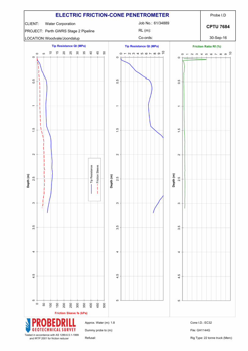
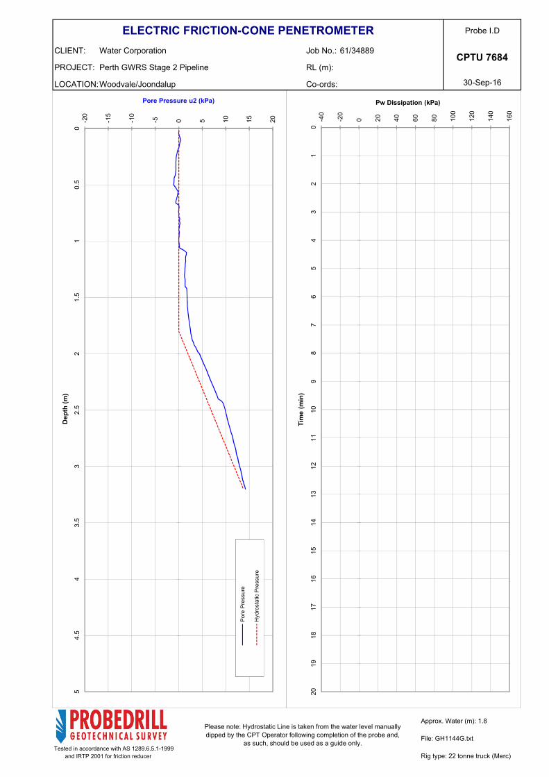
Probe I.DELECTRIC FRICTION-CONE PENETROMETER
CPTU 7684
Rig Type: 22 tonne truck (Merc)Tested in accordance with AS 1289.6.5.1-1999 and IRTP 2001 for friction reducer
61/34889
Woodvale/Joondalup
Perth GWRS Stage 2 Pipeline
Water Corporation
Refusal:
Approx. Water (m): 1.8
Dummy probe to (m): File: GH1144G
Cone I.D.: EC32
0 1 2 3 4 5 6 7 8 9 10
00.
51
1.5
22.
53
3.5
44.
55
Friction Ratio Rf (%)
Dep
th (m
)
0 1 2 3 4 5 6 7 8 9 10
00.
51
1.5
22.
53
3.5
44.
55
Tip Resistance Qt (MPa)
Dep
th (m
)
0 50 100
150
200
250
300
350
400
450
500
0 5 10 15 20 25 30 35 40 45 50
00.
51
1.5
22.
53
3.5
44.
55
Friction Sleeve fs (kPa)
Tip Resistance Qt (MPa)
Dep
th (m
)
Tip
Res
ista
nce
Fric
tion
Slee
ve
LOCATION:
PROJECT:
CLIENT:
Co-ords:
RL (m):
Job No.:
30-Sep-16
Probe I.D
Approx. Water (m): 1.8Please note: Hydrostatic Line is taken from the water level manually dipped by the CPT Operator following completion of the probe and,
as such, should be used as a guide only.
ELECTRIC FRICTION-CONE PENETROMETER
Rig type: 22 tonne truck (Merc)
CPTU 7684
Tested in accordance with AS 1289.6.5.1-1999 and IRTP 2001 for friction reducer
Water Corporation
Perth GWRS Stage 2 Pipeline
Woodvale/Joondalup
61/34889
File: GH1144G.txt
-40
-20
0 20 40 60 80 100
120
140
160
01
23
45
67
89
1011
1213
1415
1617
1819
20
Pw Dissipation (kPa)
Tim
e (m
in)
-20
-15
-10
-5 0 5 10 15 20
00.
51
1.5
22.
53
3.5
44.
55
Pore Pressure u2 (kPa)
Dep
th (m
)
Pore
Pre
ssur
e
Hyd
rost
atic
Pre
ssur
e
LOCATION:
PROJECT:
CLIENT:
Co-ords:
RL (m):
Job No.:
30-Sep-16
Probe I.DELECTRIC FRICTION-CONE PENETROMETER
CPTU 8006
Rig Type: 22 tonne truck (Merc)Tested in accordance with AS 1289.6.5.1-1999 and IRTP 2001 for friction reducer
61/34889
Woodvale/Joondalup
Perth GWRS Stage 2 Pipeline
Water Corporation
Refusal:
Approx. Water (m): 0.9
Dummy probe to (m): File: GH1145G
Cone I.D.: EC32
0 1 2 3 4 5 6 7 8 9 10
00.
51
1.5
22.
53
3.5
44.
55
Friction Ratio Rf (%)
Dep
th (m
)
0 1 2 3 4 5 6 7 8 9 10
00.
51
1.5
22.
53
3.5
44.
55
Tip Resistance Qt (MPa)
Dep
th (m
)
0 50 100
150
200
250
300
350
400
450
500
0 5 10 15 20 25 30 35 40 45 50
00.
51
1.5
22.
53
3.5
44.
55
Friction Sleeve fs (kPa)
Tip Resistance Qt (MPa)
Dep
th (m
)
Tip
Res
ista
nce
Fric
tion
Slee
ve
LOCATION:
PROJECT:
CLIENT:
Co-ords:
RL (m):
Job No.:
30-Sep-16
Probe I.D
Approx. Water (m): 0.9Please note: Hydrostatic Line is taken from the water level manually dipped by the CPT Operator following completion of the probe and,
as such, should be used as a guide only.
ELECTRIC FRICTION-CONE PENETROMETER
Rig type: 22 tonne truck (Merc)
CPTU 8006
Tested in accordance with AS 1289.6.5.1-1999 and IRTP 2001 for friction reducer
Water Corporation
Perth GWRS Stage 2 Pipeline
Woodvale/Joondalup
61/34889
File: GH1145G.txt
-40
-20
0 20 40 60 80 100
120
140
160
01
23
45
67
89
1011
1213
1415
1617
1819
20
Pw Dissipation (kPa)
Tim
e (m
in)
-40
-35
-30
-25
-20
-15
-10
-5 0 5 10 15 20 25 30
00.
51
1.5
22.
53
3.5
44.
55
Pore Pressure u2 (kPa)
Dep
th (m
)
Pore
Pre
ssur
e
Hyd
rost
atic
Pre
ssur
e
LOCATION:
PROJECT:
CLIENT:
Co-ords:
RL (m):
Job No.:
30-Sep-16
Probe I.DELECTRIC FRICTION-CONE PENETROMETER
CPTU 8378
Rig Type: 22 tonne truck (Merc)Tested in accordance with AS 1289.6.5.1-1999 and IRTP 2001 for friction reducer
61/34889
Woodvale/Joondalup
Perth GWRS Stage 2 Pipeline
Water Corporation
Refusal:
Approx. Water (m): 1.7
Dummy probe to (m): File: GH1146G
Cone I.D.: EC32
0 1 2 3 4 5 6 7 8 9 10
00.
51
1.5
22.
53
3.5
44.
55
Friction Ratio Rf (%)
Dep
th (m
)
0 1 2 3 4 5 6 7 8 9 10
00.
51
1.5
22.
53
3.5
44.
55
Tip Resistance Qt (MPa)
Dep
th (m
)
0 50 100
150
200
250
300
350
400
450
500
0 5 10 15 20 25 30 35 40 45 50
00.
51
1.5
22.
53
3.5
44.
55
Friction Sleeve fs (kPa)
Tip Resistance Qt (MPa)
Dep
th (m
)
Tip
Res
ista
nce
Fric
tion
Slee
ve
LOCATION:
PROJECT:
CLIENT:
Co-ords:
RL (m):
Job No.:
30-Sep-16
Probe I.D
Approx. Water (m): 1.7Please note: Hydrostatic Line is taken from the water level manually dipped by the CPT Operator following completion of the probe and,
as such, should be used as a guide only.
ELECTRIC FRICTION-CONE PENETROMETER
Rig type: 22 tonne truck (Merc)
CPTU 8378
Tested in accordance with AS 1289.6.5.1-1999 and IRTP 2001 for friction reducer
Water Corporation
Perth GWRS Stage 2 Pipeline
Woodvale/Joondalup
61/34889
File: GH1146G.txt
-40
-20
0 20 40 60 80 100
120
140
160
01
23
45
67
89
1011
1213
1415
1617
1819
20
Pw Dissipation (kPa)
Tim
e (m
in)
-20
-15
-10
-5 0 5 10 15 20
00.
51
1.5
22.
53
3.5
44.
55
Pore Pressure u2 (kPa)
Dep
th (m
)
Pore
Pre
ssur
e
Hyd
rost
atic
Pre
ssur
e
LOCATION:
PROJECT:
CLIENT:
Co-ords:
RL (m):
Job No.:
30-Sep-16
Probe I.DELECTRIC FRICTION-CONE PENETROMETER
CPTU 8728
Rig Type: 22 tonne truck (Merc)Tested in accordance with AS 1289.6.5.1-1999 and IRTP 2001 for friction reducer
61/34889
Woodvale/Joondalup
Perth GWRS Stage 2 Pipeline
Water Corporation
Refusal:
Approx. Water (m): Dry to 3.2
Dummy probe to (m): File: GH1147G
Cone I.D.: EC32
0 1 2 3 4 5 6 7 8 9 10
00.
51
1.5
22.
53
3.5
44.
55
Friction Ratio Rf (%)
Dep
th (m
)
0 1 2 3 4 5 6 7 8 9 10
00.
51
1.5
22.
53
3.5
44.
55
Tip Resistance Qt (MPa)
Dep
th (m
)
0 50 100
150
200
250
300
350
400
450
500
0 5 10 15 20 25 30 35 40 45 50
00.
51
1.5
22.
53
3.5
44.
55
Friction Sleeve fs (kPa)
Tip Resistance Qt (MPa)
Dep
th (m
)
Tip
Res
ista
nce
Fric
tion
Slee
ve
LOCATION:
PROJECT:
CLIENT:
Co-ords:
RL (m):
Job No.:
30-Sep-16
Probe I.D
Approx. Water (m): Dry to 3.2Please note: Hydrostatic Line is taken from the water level manually dipped by the CPT Operator following completion of the probe and,
as such, should be used as a guide only.
ELECTRIC FRICTION-CONE PENETROMETER
Rig type: 22 tonne truck (Merc)
CPTU 8728
Tested in accordance with AS 1289.6.5.1-1999 and IRTP 2001 for friction reducer
Water Corporation
Perth GWRS Stage 2 Pipeline
Woodvale/Joondalup
61/34889
File: GH1147G.txt
-40
-20
0 20 40 60 80 100
120
140
160
01
23
45
67
89
1011
1213
1415
1617
1819
20
Pw Dissipation (kPa)
Tim
e (m
in)
-20
-15
-10
-5 0 5 10 15 20
00.
51
1.5
22.
53
3.5
44.
55
Pore Pressure u2 (kPa)
Dep
th (m
)
Pore
Pre
ssur
e
Hyd
rost
atic
Pre
ssur
e
LOCATION:
PROJECT:
CLIENT:
Co-ords:
RL (m):
Job No.:
30-Sep-16
Probe I.DELECTRIC FRICTION-CONE PENETROMETER
CPTU 9389
Rig Type: 22 tonne truck (Merc)Tested in accordance with AS 1289.6.5.1-1999 and IRTP 2001 for friction reducer
61/34889
Woodvale/Joondalup
Perth GWRS Stage 2 Pipeline
Water Corporation
Refusal:
Approx. Water (m): Dry to 3.2
Dummy probe to (m): File: GH1134G
Cone I.D.: EC32
0 1 2 3 4 5 6 7 8 9 10
00.
51
1.5
22.
53
3.5
44.
55
Friction Ratio Rf (%)
Dep
th (m
)
0 1 2 3 4 5 6 7 8 9 10
00.
51
1.5
22.
53
3.5
44.
55
Tip Resistance Qt (MPa)
Dep
th (m
)
0 50 100
150
200
250
300
350
400
450
500
0 5 10 15 20 25 30 35 40 45 50
00.
51
1.5
22.
53
3.5
44.
55
Friction Sleeve fs (kPa)
Tip Resistance Qt (MPa)
Dep
th (m
)
Tip
Res
ista
nce
Fric
tion
Slee
ve
LOCATION:
PROJECT:
CLIENT:
Co-ords:
RL (m):
Job No.:
30-Sep-16
Probe I.D
Approx. Water (m): Dry to 3.2Please note: Hydrostatic Line is taken from the water level manually dipped by the CPT Operator following completion of the probe and,
as such, should be used as a guide only.
ELECTRIC FRICTION-CONE PENETROMETER
Rig type: 22 tonne truck (Merc)
CPTU 9389
Tested in accordance with AS 1289.6.5.1-1999 and IRTP 2001 for friction reducer
Water Corporation
Perth GWRS Stage 2 Pipeline
Woodvale/Joondalup
61/34889
File: GH1134G.txt
-40
-20
0 20 40 60 80 100
120
140
160
01
23
45
67
89
1011
1213
1415
1617
1819
20
Pw Dissipation (kPa)
Tim
e (m
in)
-20
-15
-10
-5 0 5 10 15 20
00.
51
1.5
22.
53
3.5
44.
55
Pore Pressure u2 (kPa)
Dep
th (m
)
Pore
Pre
ssur
e
Hyd
rost
atic
Pre
ssur
e
LOCATION:
PROJECT:
CLIENT:
Co-ords:
RL (m):
Job No.:
30-Sep-16
Probe I.DELECTRIC FRICTION-CONE PENETROMETER
CPTU 9724
Rig Type: 22 tonne truck (Merc)Tested in accordance with AS 1289.6.5.1-1999 and IRTP 2001 for friction reducer
61/34889
Woodvale/Joondalup
Perth GWRS Stage 2 Pipeline
Water Corporation
Refusal:
Approx. Water (m): Dry to 3.2
Dummy probe to (m): File: GH1133G
Cone I.D.: EC32
0 1 2 3 4 5 6 7 8 9 10
00.
51
1.5
22.
53
3.5
44.
55
Friction Ratio Rf (%)
Dep
th (m
)
0 1 2 3 4 5 6 7 8 9 10
00.
51
1.5
22.
53
3.5
44.
55
Tip Resistance Qt (MPa)
Dep
th (m
)
0 50 100
150
200
250
300
350
400
450
500
0 5 10 15 20 25 30 35 40 45 50
00.
51
1.5
22.
53
3.5
44.
55
Friction Sleeve fs (kPa)
Tip Resistance Qt (MPa)
Dep
th (m
)
Tip
Res
ista
nce
Fric
tion
Slee
ve
LOCATION:
PROJECT:
CLIENT:
Co-ords:
RL (m):
Job No.:
30-Sep-16
Probe I.D
Approx. Water (m): Dry to 3.2Please note: Hydrostatic Line is taken from the water level manually dipped by the CPT Operator following completion of the probe and,
as such, should be used as a guide only.
ELECTRIC FRICTION-CONE PENETROMETER
Rig type: 22 tonne truck (Merc)
CPTU 9724
Tested in accordance with AS 1289.6.5.1-1999 and IRTP 2001 for friction reducer
Water Corporation
Perth GWRS Stage 2 Pipeline
Woodvale/Joondalup
61/34889
File: GH1133G.txt
-40
-20
0 20 40 60 80 100
120
140
160
01
23
45
67
89
1011
1213
1415
1617
1819
20
Pw Dissipation (kPa)
Tim
e (m
in)
-20
-15
-10
-5 0 5 10 15 20
00.
51
1.5
22.
53
3.5
44.
55
Pore Pressure u2 (kPa)
Dep
th (m
)
Pore
Pre
ssur
e
Hyd
rost
atic
Pre
ssur
e
LOCATION:
PROJECT:
CLIENT:
Co-ords:
RL (m):
Job No.:
30-Sep-16
Probe I.DELECTRIC FRICTION-CONE PENETROMETER
CPTU 10055
Rig Type: 22 tonne truck (Merc)Tested in accordance with AS 1289.6.5.1-1999 and IRTP 2001 for friction reducer
61/34889
Woodvale/Joondalup
Perth GWRS Stage 2 Pipeline
Water Corporation
Refusal:
Approx. Water (m): 2.1
Dummy probe to (m): File: GH1135G
Cone I.D.: EC32
0 1 2 3 4 5 6 7 8 9 10
00.
51
1.5
22.
53
3.5
44.
55
Friction Ratio Rf (%)
Dep
th (m
)
0 1 2 3 4 5 6 7 8 9 10
00.
51
1.5
22.
53
3.5
44.
55
Tip Resistance Qt (MPa)
Dep
th (m
)
0 50 100
150
200
250
300
350
400
450
500
0 5 10 15 20 25 30 35 40 45 50
00.
51
1.5
22.
53
3.5
44.
55
Friction Sleeve fs (kPa)
Tip Resistance Qt (MPa)
Dep
th (m
)
Tip
Res
ista
nce
Fric
tion
Slee
ve
LOCATION:
PROJECT:
CLIENT:
Co-ords:
RL (m):
Job No.:
30-Sep-16
Probe I.D
Approx. Water (m): 2.1Please note: Hydrostatic Line is taken from the water level manually dipped by the CPT Operator following completion of the probe and,
as such, should be used as a guide only.
ELECTRIC FRICTION-CONE PENETROMETER
Rig type: 22 tonne truck (Merc)
CPTU 10055
Tested in accordance with AS 1289.6.5.1-1999 and IRTP 2001 for friction reducer
Water Corporation
Perth GWRS Stage 2 Pipeline
Woodvale/Joondalup
61/34889
File: GH1135G.txt
-40
-20
0 20 40 60 80 100
120
140
160
01
23
45
67
89
1011
1213
1415
1617
1819
20
Pw Dissipation (kPa)
Tim
e (m
in)
-20
-15
-10
-5 0 5 10 15 20
00.
51
1.5
22.
53
3.5
44.
55
Pore Pressure u2 (kPa)
Dep
th (m
)
Pore
Pre
ssur
e
Hyd
rost
atic
Pre
ssur
e
LOCATION:
PROJECT:
CLIENT:
Co-ords:
RL (m):
Job No.:
30-Sep-16
Probe I.DELECTRIC FRICTION-CONE PENETROMETER
CPTU 10425
Rig Type: 22 tonne truck (Merc)Tested in accordance with AS 1289.6.5.1-1999 and IRTP 2001 for friction reducer
61/34889
Woodvale/Joondalup
Perth GWRS Stage 2 Pipeline
Water Corporation
Refusal:
Approx. Water (m): 0.1
Dummy probe to (m): File: GH1136G
Cone I.D.: EC32
0 1 2 3 4 5 6 7 8 9 10
00.
51
1.5
22.
53
3.5
44.
55
Friction Ratio Rf (%)
Dep
th (m
)
0 1 2 3 4 5 6 7 8 9 10
00.
51
1.5
22.
53
3.5
44.
55
Tip Resistance Qt (MPa)
Dep
th (m
)
0 50 100
150
200
250
300
350
400
450
500
0 5 10 15 20 25 30 35 40 45 50
00.
51
1.5
22.
53
3.5
44.
55
Friction Sleeve fs (kPa)
Tip Resistance Qt (MPa)
Dep
th (m
)
Tip
Res
ista
nce
Fric
tion
Slee
ve
LOCATION:
PROJECT:
CLIENT:
Co-ords:
RL (m):
Job No.:
30-Sep-16
Probe I.D
Approx. Water (m): 0.1Please note: Hydrostatic Line is taken from the water level manually dipped by the CPT Operator following completion of the probe and,
as such, should be used as a guide only.
ELECTRIC FRICTION-CONE PENETROMETER
Rig type: 22 tonne truck (Merc)
CPTU 10425
Tested in accordance with AS 1289.6.5.1-1999 and IRTP 2001 for friction reducer
Water Corporation
Perth GWRS Stage 2 Pipeline
Woodvale/Joondalup
61/34889
File: GH1136G.txt
-40
-20
0 20 40 60 80 100
120
140
160
01
23
45
67
89
1011
1213
1415
1617
1819
20
Pw Dissipation (kPa)
Tim
e (m
in)
-10
-5 0 5 10 15 20 25 30 35 40
00.
51
1.5
22.
53
3.5
44.
55
Pore Pressure u2 (kPa)
Dep
th (m
)
Pore
Pre
ssur
e
Hyd
rost
atic
Pre
ssur
e
LOCATION:
PROJECT:
CLIENT:
Co-ords:
RL (m):
Job No.:
30-Sep-16
Probe I.DELECTRIC FRICTION-CONE PENETROMETER
CPTU 11345
Rig Type: 22 tonne truck (Merc)Tested in accordance with AS 1289.6.5.1-1999 and IRTP 2001 for friction reducer
61/34889
Woodvale/Joondalup
Perth GWRS Stage 2 Pipeline
Water Corporation
Refusal:
Approx. Water (m): Dry to 3.2
Dummy probe to (m): File: GH1137G
Cone I.D.: EC32
0 1 2 3 4 5 6 7 8 9 10
00.
51
1.5
22.
53
3.5
44.
55
Friction Ratio Rf (%)
Dep
th (m
)
0 1 2 3 4 5 6 7 8 9 10
00.
51
1.5
22.
53
3.5
44.
55
Tip Resistance Qt (MPa)
Dep
th (m
)
0 50 100
150
200
250
300
350
400
450
500
0 5 10 15 20 25 30 35 40 45 50
00.
51
1.5
22.
53
3.5
44.
55
Friction Sleeve fs (kPa)
Tip Resistance Qt (MPa)
Dep
th (m
)
Tip
Res
ista
nce
Fric
tion
Slee
ve
LOCATION:
PROJECT:
CLIENT:
Co-ords:
RL (m):
Job No.:
30-Sep-16
Probe I.D
Approx. Water (m): Dry to 3.2Please note: Hydrostatic Line is taken from the water level manually dipped by the CPT Operator following completion of the probe and,
as such, should be used as a guide only.
ELECTRIC FRICTION-CONE PENETROMETER
Rig type: 22 tonne truck (Merc)
CPTU 11345
Tested in accordance with AS 1289.6.5.1-1999 and IRTP 2001 for friction reducer
Water Corporation
Perth GWRS Stage 2 Pipeline
Woodvale/Joondalup
61/34889
File: GH1137G.txt
-40
-20
0 20 40 60 80 100
120
140
160
01
23
45
67
89
1011
1213
1415
1617
1819
20
Pw Dissipation (kPa)
Tim
e (m
in)
-20
-15
-10
-5 0 5 10 15 20
00.
51
1.5
22.
53
3.5
44.
55
Pore Pressure u2 (kPa)
Dep
th (m
)
Pore
Pre
ssur
e
Hyd
rost
atic
Pre
ssur
e
LOCATION:
PROJECT:
CLIENT:
Co-ords:
RL (m):
Job No.:
30-Sep-16
Probe I.DELECTRIC FRICTION-CONE PENETROMETER
CPTU 11702
Rig Type: 22 tonne truck (Merc)Tested in accordance with AS 1289.6.5.1-1999 and IRTP 2001 for friction reducer
61/34889
Woodvale/Joondalup
Perth GWRS Stage 2 Pipeline
Water Corporation
Refusal:
Approx. Water (m): Dry to 3.2
Dummy probe to (m): File: GH1138G
Cone I.D.: EC32
0 1 2 3 4 5 6 7 8 9 10
00.
51
1.5
22.
53
3.5
44.
55
Friction Ratio Rf (%)
Dep
th (m
)
0 1 2 3 4 5 6 7 8 9 10
00.
51
1.5
22.
53
3.5
44.
55
Tip Resistance Qt (MPa)
Dep
th (m
)
0 50 100
150
200
250
300
350
400
450
500
0 5 10 15 20 25 30 35 40 45 50
00.
51
1.5
22.
53
3.5
44.
55
Friction Sleeve fs (kPa)
Tip Resistance Qt (MPa)
Dep
th (m
)
Tip
Res
ista
nce
Fric
tion
Slee
ve
LOCATION:
PROJECT:
CLIENT:
Co-ords:
RL (m):
Job No.:
30-Sep-16
Probe I.D
Approx. Water (m): Dry to 3.2Please note: Hydrostatic Line is taken from the water level manually dipped by the CPT Operator following completion of the probe and,
as such, should be used as a guide only.
ELECTRIC FRICTION-CONE PENETROMETER
Rig type: 22 tonne truck (Merc)
CPTU 11702
Tested in accordance with AS 1289.6.5.1-1999 and IRTP 2001 for friction reducer
Water Corporation
Perth GWRS Stage 2 Pipeline
Woodvale/Joondalup
61/34889
File: GH1138G.txt
-40
-20
0 20 40 60 80 100
120
140
160
01
23
45
67
89
1011
1213
1415
1617
1819
20
Pw Dissipation (kPa)
Tim
e (m
in)
-20
-15
-10
-5 0 5 10 15 20
00.
51
1.5
22.
53
3.5
44.
55
Pore Pressure u2 (kPa)
Dep
th (m
)
Pore
Pre
ssur
e
Hyd
rost
atic
Pre
ssur
e
LOCATION:
PROJECT:
CLIENT:
Co-ords:
RL (m):
Job No.:
30-Sep-16
Probe I.DELECTRIC FRICTION-CONE PENETROMETER
CPTU 12390
Rig Type: 22 tonne truck (Merc)Tested in accordance with AS 1289.6.5.1-1999 and IRTP 2001 for friction reducer
61/34889
Woodvale/Joondalup
Perth GWRS Stage 2 Pipeline
Water Corporation
Refusal:
Approx. Water (m): Dry to 3.2
Dummy probe to (m): File: GH1139G
Cone I.D.: EC32
0 1 2 3 4 5 6 7 8 9 10
00.
51
1.5
22.
53
3.5
44.
55
Friction Ratio Rf (%)
Dep
th (m
)
0 1 2 3 4 5 6 7 8 9 10
00.
51
1.5
22.
53
3.5
44.
55
Tip Resistance Qt (MPa)
Dep
th (m
)
0 50 100
150
200
250
300
350
400
450
500
0 5 10 15 20 25 30 35 40 45 50
00.
51
1.5
22.
53
3.5
44.
55
Friction Sleeve fs (kPa)
Tip Resistance Qt (MPa)
Dep
th (m
)
Tip
Res
ista
nce
Fric
tion
Slee
ve
LOCATION:
PROJECT:
CLIENT:
Co-ords:
RL (m):
Job No.:
30-Sep-16
Probe I.D
Approx. Water (m): Dry to 3.2Please note: Hydrostatic Line is taken from the water level manually dipped by the CPT Operator following completion of the probe and,
as such, should be used as a guide only.
ELECTRIC FRICTION-CONE PENETROMETER
Rig type: 22 tonne truck (Merc)
CPTU 12390
Tested in accordance with AS 1289.6.5.1-1999 and IRTP 2001 for friction reducer
Water Corporation
Perth GWRS Stage 2 Pipeline
Woodvale/Joondalup
61/34889
File: GH1139G.txt
-40
-20
0 20 40 60 80 100
120
140
160
01
23
45
67
89
1011
1213
1415
1617
1819
20
Pw Dissipation (kPa)
Tim
e (m
in)
-20
-15
-10
-5 0 5 10 15 20
00.
51
1.5
22.
53
3.5
44.
55
Pore Pressure u2 (kPa)
Dep
th (m
)
Pore
Pre
ssur
e
Hyd
rost
atic
Pre
ssur
e
GHD | Report for Water Corporation - Perth GWR Stage 2, 61/34889
Appendix B – Borehole Logs
ROCK TYPES:
NRRX
S
N
Fine Grained
Igneous:
Medium Grained
Coarse Grained
DOLERITE
RRock fragment
Rock core
Sedimentary:
Slow inflow/ seepageinto excavation
Permanent water level
SAMPLE TYPES:
COBBLES & BOULDERS
HIGHLY ORGANIC/ PEAT
MADE GROUND/ FILL
Inflow into excavationor borehole
Outflow/ water lossin borehole
Temporary water level
Disturbed bag sample
Bulk disturbed (>20kg)
Auger flight cuttings
Hollow stem auger core
SPT with no sample recovery
Attempted samplewith no recovery
D
A
AX
B
U(xx)
U(35)
Core Loss:
SILTSTONE
SANDSTONE
Medium Grained
Fine Grained
Coarse Grained
Metamorphic:CONGLOMERATE
BRECCIA
SHALE
CLAYSTONE/ MUDSTONE
LIMESTONE
Carbonate CLAYSTONE/CALCILUTITE
Carbonate SILTSTONE/CALCISILTITE
Carbonate CONGLOMERATE/CALCIRUDITE
Carbonate SANDSTONE/CALCARENITE
Evaporites:
GYPSUM or HALITE
CHALK
Carbonates:
High Plasticity
Low Plasticity
High Plasticity
Low Plasticity
SILT
CLAY
Composite soil types signified by combined symbols; eg. Silty SAND
SYMBOLS LEGEND FOR GEOTECHNICAL LOGS
Standard Penetration Test(SPT), with disturbedsplit-spoon sample
Small diameter (35mm)thin walled tube
SOIL TYPES:
GRAVEL
SAND
Poorly Graded
Well Graded
Poorly Graded
Well Graded
GROUNDWATER OBSERVATIONS:
Thin walled tube, withdiameter "xx" generally50 to 100 (mm)
Soil DescriptionAll geotechnical logging is carried out in general accordance with Australian Standard AS 1726 - 1993“Geotechnical site investigations”. The description of soils is based on the Unified Soil ClassificationSystem (Table A1, AS 1726-1993).
The top section of the log is self explanatory giving details of the project including the client, location, jobnumber, drill contractor, date, logger, drilling information and survey data.
The main part of the log provides details and physical parameters of the soil material relative to a depthscale. This also includes the depth of the various drill methods and casing used and standing watertables and geological units intersected. The descriptive information includes soil type, plasticity, particlesize, colour and minor components.
Soil Type
Abbreviation Description
GW Well-graded gravels, gravel-sand mixtures, little or no fines
GP Poorly graded gravels and gravel-sand mixtures, little or no fines
GM Silty gravels, gravel-sand-silt mixtures
GC Clayey gravels, gravel-sand-clay mixture
SW Well graded sand, gravelly sands, little or no fines
SP Poorly graded sands and gravelly sands; little or no fines, uniform sands
SM Silty sand, sand-silt mixtures
SC Clayey sands, sand-clay mixtures
ML Inorganic silts and very fine sands, rock flour, silty or clayey fine sand or clayey siltswith slight plasticity
CL/CI Inorganic clays of low to medium plasticity, gravelly clays, sandy clays, silty clays,lean clays
OL Organic silts and organic silty clays of low plasticity
MH Inorganic silts, micaceous or diatomaceous fine sandy or silty soils, elastic silts
CH Inorganic clays of high plasticity, organic silts
OH Organic clays of medium to high plasticity, organic silts
Pt Peat and other highly organic soils
ColourColour is important for correlation of data between test holes and during subsequent excavationoperations. The prominent colour is noted, followed by spotted, mottled, streaked etc., then secondarycolours as applicable. Colour is usually described at as-received moisture condition, though both wetand dry colours may also be appropriate.
Moisture ConditionTerms used to describe the moisture condition of the soils encountered, based on appearance and feel,include:
Abbreviation Terms Description
D Dry Looks and feels dry. Cohesive soils usually hard, and friable orpowdery, well dry of plastic limit. Granular soils are cohesionless andfree-running.
M Moist Feels cool, darkened in colour. Cohesive soils can be moulded by hand.Granular soils tend to cohere.
W Wet Feels cool, darkened in colour. Cohesive soils usually weakened andfree water forms on hands when remoulding. Granular soils tend tocohere.
Consistency / Relative DensityThe consistency of cohesive soils is based on the undrained shear strength and is generally estimated,with or without the aid of a pocket penetrometer or hand vane testing. Terms used to describeconsistency include:
Abbreviation Term Undrained Shear Strength kPa
VS Very Soft ≤12
S Soft >12 ≤ 25
F Firm >25 ≤ 50
St Stiff >50 ≤ 100
VSt Very Stiff >100 ≤ 200
H Hard >200
The relative density of non-cohesive soils is described in terms of the density index. It is not possibleto make an assessment of the density index without some form of test on an undisturbed or in situsample. Terms used to describe relative density include:
Abbreviation Term Density Index (%)
VL Very Loose ≤15
L Loose >15 ≤ 35
MD Medium Dense >35 ≤ 65
D Dense >65 ≤ 85
VD Very Dense >85
Where consistency or relative density has not been determined this is noted by the abbreviation “ND”.
CementationThe description of carbonate rock types and soils in accordance with the classification is given by Clark,A.R. and Walker, B.F. Geotechnique, 1977, 27(1), 93-99. Rock and soil cementation terms are definedbelow:
Abbreviation Term Description
Uc Uncemented Slakes when immersed in water
VWk Very weaklycemented
Near uncemented sand
Wk Weakly cemented Very soft rock, crushed between fingers
Mo Moderately wellcemented
Soft rock, easily scratched, generally friable, rock core canbe broken by hand
We Well cemented Hard rock, can be scratched with thumbnail, requiressubstantial effort to break core
VWe Very well cemented Generally very hard rock, cannot be scratched easily, corecan be broken with blow from hammer
Structure/Other FeaturesThe soil structure is generally applicable to cohesive soils and mainly refers to the presence or absenceof joints and layering. Typical terms use are intact (no joints), fissured (closed joints), shattered (openjoints), slickensided (polished joints indicative of movement), and stratified/laminated. In addition, thepresence of other features (ferricrete nodules, timber inclusions) should also be noted as applicable.
For granular soils, an assessment of grading (well, uniform or poor), particle size (fine, medium etc.),angularity and shape may also be given.
OriginAn attempt is made, where possible, to assess origin (transported, residual, pedogenic or fill etc.) sincethis assists in the judgement of probable engineering behaviour. This assessment is generally restrictedto field logging activities. An interpretation of landform is a useful guide to the origin of transported soils(e.g. colluvium, talus, slide debris, slope wash, alluvium, lacustrine, estuarine, aeolian and littoraldeposits) while local geology and remnant fabric will assist identification of residual soils.
Sample TypesRefer to “Symbols Legend for Geotechnical Logs” for indications of retrieved sample types.
Rock DescriptionAll geotechnical logging is carried out in general accordance with Australian Standard AS 1726 - 1993“Geotechnical site investigations”. The description of soils is based on the Unified Soil ClassificationSystem. For rocks, the descriptions are based on the generalised method outlined below.
The top section of the log is self explanatory giving details of the project including the client, location, drillcontractor, job number, date, logger, drilling information and survey data.
The main part of the log provides details and physical parameters of the material (soil or rock) relative toa depth scale. This also includes the depth of the various drill methods and casing, standing watertables and geological units intersected. The descriptive information includes rock (or soil) type, grainsize, texture/fabric, colour and minor inclusions.
Rock WeatheringRock material weathering terms are defined below. Note that the terms are a combination of those usedin AS 1726 - 1981 & 1993. It is noted, however, that the assignment of a term of weathering is subjectiveand is normally used for identification and does not imply engineering behaviour (such behaviour beingcontrolled principally by rock substances strength and defect frequency-collectively, rock mass strength).Consequently, boundaries are often not shown and weathering may even not reported where potentiallymisleading.
Rock Type Abbreviation Description
Residual Soil RS Soil developed on extremely weathered rock, the mass structureand substance fabric are no longer evident, there is a largechange in volume but the soil has not been significantlytransported.
ExtremelyWeathered
EW Rock is weathered to such an extent that it has “soil” properties i.e.it either disintegrates or can be remoulded in water.
ModeratelyWeathered
MW Rock is weathered to such an extent that it shows a visible changein appearance with significant loss in strength.
Highly Weathered HW Rock is weathered to such an extent that it shows considerablechange in appearance and loss in strength. Material is still a rockbut normally very weak.
Slightly Weathered SW Rock is slightly discoloured but shows little or no change ofstrength from fresh rock.
Fresh FR Rock shows no sign of decomposition or staining.
CementationThe description of carbonate rock types and soils in accordance with the classification is given by Clark,A.R. and Walker, B.F. Geotechnique, 1977, 27(1), 93-99. Rock and material cementation terms aredefined below:
Wk Weakly cemented Very soft rock, crushed between fingers
Mo Moderately wellcemented
Soft rock, easily scratched, generally friable, rock core can bebroken by hand
We Well cemented Hard rock, can be scratched with thumbnail, requiressubstantial effort to break core
VWe Very well cemented Generally very hard rock, cannot be scratched easily, core canbe broken with blow from hammer
Estimated Rock StrengthRock strength terms are defined below based on Point Load Strength Index Is(50). Note that in theabsence of point load testing, estimated strengths are used based on the field guide in AS 1726 - 1993.
Abbreviation Term UCS (MPa) Point Load Strength Index IS(50)(MPa)
EL Extremely Low < 0.7 ≤0.03
VL Very Low 0.7 – 2.4 >0.03 ≤ 0.1
L Low 2.4 – 7.0 >0.1 ≤ 0.3
M Medium 7.0 – 24.0 >0.3 ≤ 1
H High 24.0 – 70.0 >1 ≤ 3
VH Very High 70.0 – 240.0 >3 ≤ 10
EH Extremely High > 240.0 >10
Note: There is no direct correlation between UCS and point load strength. It is dependent on the rock type and weathering grade.
Run and RecoveryEach run of the core barrel is counted as one run. Core recovery represents the ratio of core recoveredto the length drilled for the corresponding core run and is expressed as a percentage.
Solid Core Recovery (SCR)SCR is the ratio of solid core recovered to length of core run. It has a full diameter, uninterrupted bynatural discontinuities, but not necessarily a full circumference and is commonly measured along thecore axis or other scan line.
Rock Quality Designation (RQD)RQD is the ratio of the length of sound core recovered in pieces over 10cm to the length of core rundrilled. Mechanical breaks are discounted. RQD is not determined on extremely to highly weatheredrock. The descriptive terms assigned to RQD are as follows:
RQD (%) Rock Quality
<25 Very poor
25 to 50 Poor
50 to 75 Fair
75 to 90 Good
90 to 100 Excellent
Fracture FrequencyIt is a count of the number or spacing of fractures over an arbitrary length of core of similar intensity offracturing. It is usually specified as number of fracture/s per meter.
Defect LogGraphical description of each defect in the recovered core sample encountered during logging. Thisimportant feature can control the overall engineering behaviour of a rock mass. All types of naturalfractures across with the core is discontinuous are noted. These fractures include bedding planepartings, joints and other defects but exclude artificial fractures such as drilling breaks. The nature of thedefects (joints, bedding partings, seams, zones and veins) is also noted with natural factures excludesbedding partings unless there is evidence that they were separated prior to drilling. This notwithstanding,bedding partings maybe considered as planes of weakness in an engineering assessment.
Field Records and CommentsAnnotated description of rock defects including inclination/dip, type, aperture, type and amount of infillingmaterial, planarity, roughness, spacing and other comments (as necessary). The description format of anindividual defect is as follows:
type Inclination* aperture infilling amount planarity roughness spacing
J 30º Mw Cl Fi St R M
*Inclination (°) - measured generally from long axis of core.
Spacing spacing of a defect is described as follows:
Abbre Term Width (mm)
Ew Extremely Wide > 2000
W Wide 600 - 2000
M Moderate 200 - 600
C Close 60 - 200
Vc Very Close 20 - 60
Ec ExtremelyClose < 20
Other Descriptors
NA – not applicable
ND – not determined
Db – mechanical break/ drill break
SP
SP
SANDBrown-black, fine to coarse grained, sub-angular to sub-rounded, quartz. Trace fines.Trace rootlets and plant fibres.
SANDBrown-orange, fine to coarse grained, sub-angular to sub-rounded, quartz. Trace fines.Becoming orange with depth.
At 2.1m, brown-black band, likely cave in oftopsoil.
At 3.0m, becoming predominantly fine tomedium grained.
VL-L
M
1.5 SPT: 3, 3, 2 [N=5]Recovery=0.45m
3.0 SPT: 2, 1, 3 [N=4]Recovery=0.45m
4.5 SPT: 2, 2, 2 [N=4]Recovery=0.45m
Grass surface, adjacent toaccess track.
0.6-6.0m, 2x Bulk sample
1.5-3.0m run recovery of 0.4m
3.0-4.5m run recovery of 0.4m
1.50
3.00
4.50
S
S
S
Han
d A
uger
Dir
ect P
ush
Gro
undw
ater
not
inte
rsec
ted
TO
PS
OIL
TA
MA
LA S
AN
D
[+20.92]0.6
Sheet 1 of 2
Water Corporation
Perth GWR Stage 2
Geotechnical Investigation
61/3488903
Client:
Project:
Job No.:
Logged:
Processed:
Checked:
BH169
Coordinates: E 384 569, N 6482 696
Total Depth: 6.5m
Commenced: 04-Oct-16 Completed: 04-Oct-16
Contractor: National Geotech
BoreholeNo.:
Ground Surface Elevation: +21.5m AHD
BOREHOLE LOG
04-Oct-16
06-Dec-16
KT
SBO
GE
NE
RA
L LO
G 6
1348
890
3 -
PE
RT
H G
WR
ST
AG
E 2
.GP
J G
HD
LIB
.GD
T 6
/12
/16
Cla
ssif
icat
ion Strata Description
Hole Diameter (mm): 89
Flushing Fluid:
Inclination: Vertical
(type; colour; fines plasticity or particle characteristics;minor components; structure and/or origin)
Sample/ Test Records
& Comments
Mo
istu
re C
on
dit
ion
Co
nsi
sten
cy/
Rel
ativ
e D
ensi
ty
Sam
ple
Typ
e&
Dep
th
Sam
ple
No
.
1
2
3
4
5
1
2
3
4
5
Wat
er
Gra
ph
ic L
og
Daily Progress/Observations
Dep
th S
cale
(m
)
Dep
th S
cale
(m
)
Dep
th (
m)/
[E
lev.
]
Geo
log
ical
Un
it
Rig Type : Geoprobe 7822
Cas
ing
Dep
th (m
)
Dat
e
Dril
ling
Met
hod
Flui
d D
epth
(m)
SP SANDBrown-orange, fine to coarse grained, sub-angular to sub-rounded, quartz. Trace fines.Becoming orange with depth.
Termination Depth = 6.45m (Target Depth)
6.0 SPT: 2, 3, 2 [N=5]Recovery=0.45m
4.5-6.0m run recovery of 0.4m
ASS samples taken at 1.0m,1.9m, 3.0m, 4.5m, 6.0m
6.00
S
Dir
ect P
ush
TA
MA
LA S
AN
D
[+15.07]6.5
Sheet 2 of 2
Water Corporation
Perth GWR Stage 2
Geotechnical Investigation
61/3488903
Client:
Project:
Job No.:
Logged:
Processed:
Checked:
BH169
Coordinates: E 384 569, N 6482 696
Total Depth: 6.5m
Commenced: 04-Oct-16 Completed: 04-Oct-16
Contractor: National Geotech
BoreholeNo.:
Ground Surface Elevation: +21.5m AHD
BOREHOLE LOG
04-Oct-16
06-Dec-16
KT
SBO
GE
NE
RA
L LO
G 6
1348
890
3 -
PE
RT
H G
WR
ST
AG
E 2
.GP
J G
HD
LIB
.GD
T 6
/12
/16
Cla
ssif
icat
ion Strata Description
Hole Diameter (mm): 89
Flushing Fluid:
Inclination: Vertical
(type; colour; fines plasticity or particle characteristics;minor components; structure and/or origin)
Sample/ Test Records
& Comments
Mo
istu
re C
on
dit
ion
Co
nsi
sten
cy/
Rel
ativ
e D
ensi
ty
Sam
ple
Typ
e&
Dep
th
Sam
ple
No
.
6
7
8
9
10
6
7
8
9
10
Wat
er
Gra
ph
ic L
og
Daily Progress/Observations
Dep
th S
cale
(m
)
Dep
th S
cale
(m
)
Dep
th (
m)/
[E
lev.
]
Geo
log
ical
Un
it
Rig Type : Geoprobe 7822
Cas
ing
Dep
th (m
)
Dat
e
Dril
ling
Met
hod
Flui
d D
epth
(m)
SP
SP
SP
ASPHALTCemented pisolitic gravel
SAND with GravelPale orange, fine to medium grained, sub-angular to sub-rounded. Gravel is fine tocoarse, sub-angular, limestone, trace fines.
SANDBrown, fine to coarse grained, sub-angular tosub-rounded, quartz, trace fines.
SANDBrown-orange, fine to coarse grained,predominantly fine to medium, sub-angular tosub-rounded, quartz, trace fines.
At 3.0m, becoming orange, trace brownmottling.
At 3.25m, small root.
MD
L
M
1.5 SPT: 1, 2, 2 [N=4]Recovery=0.4m
3.0 SPT: 2, 1, 3 [N=4]Recovery=0.4m
4.5 SPT: 2, 2, 2 [N=4]Recovery=0.45m
On cycle path.
1.5-3.0m run recovery of 0.3m
3.0-4.5m run recovery of 0.45m
1.50
3.00
4.50
S
S
S
DP
Han
d A
uger
Dir
ect P
ush
Gro
undw
ater
not
inte
rsec
ted
PA
VE
TS
TA
MA
LA S
AN
D
[+25.18]
[+25.03]
[+24.78]
0.3
0.5
Sheet 1 of 2
Water Corporation
Perth GWR Stage 2
Geotechnical Investigation
61/3488903
Client:
Project:
Job No.:
Logged:
Processed:
Checked:
BH283
Coordinates: E 384 679, N 6482 693
Total Depth: 6.5m
Commenced: 10-Oct-16 Completed: 10-Oct-16
Contractor: National Geotech
BoreholeNo.:
Ground Surface Elevation: +25.3m AHD
BOREHOLE LOG
10-Oct-16
06-Dec-16
KT
SBO
GE
NE
RA
L LO
G 6
1348
890
3 -
PE
RT
H G
WR
ST
AG
E 2
.GP
J G
HD
LIB
.GD
T 6
/12
/16
Cla
ssif
icat
ion Strata Description
Hole Diameter (mm): 89
Flushing Fluid:
Inclination: Vertical
(type; colour; fines plasticity or particle characteristics;minor components; structure and/or origin)
Sample/ Test Records
& Comments
Mo
istu
re C
on
dit
ion
Co
nsi
sten
cy/
Rel
ativ
e D
ensi
ty
Sam
ple
Typ
e&
Dep
th
Sam
ple
No
.
1
2
3
4
5
1
2
3
4
5
Wat
er
Gra
ph
ic L
og
Daily Progress/Observations
Dep
th S
cale
(m
)
Dep
th S
cale
(m
)
Dep
th (
m)/
[E
lev.
]
Geo
log
ical
Un
it
Rig Type : Geoprobe 7822
Cas
ing
Dep
th (m
)
Dat
e
Dril
ling
Met
hod
Flui
d D
epth
(m)
SP SANDBrown-orange, fine to coarse grained,predominantly fine to medium, sub-angular tosub-rounded, quartz, trace fines.
Termination Depth = 6.45m (Target Depth)
6.0 SPT: 2, 3, 3 [N=6]Recovery=0.4m
4.5-6.0m run recovery of 0.55m
ASS samples taken at 1.0m,2.0m, 3.0m, 3.8m, 5.0m, 6.0m
6.00
S
Dir
ect P
ush
TA
MA
LA S
AN
D
[+18.83]6.5
Sheet 2 of 2
Water Corporation
Perth GWR Stage 2
Geotechnical Investigation
61/3488903
Client:
Project:
Job No.:
Logged:
Processed:
Checked:
BH283
Coordinates: E 384 679, N 6482 693
Total Depth: 6.5m
Commenced: 10-Oct-16 Completed: 10-Oct-16
Contractor: National Geotech
BoreholeNo.:
Ground Surface Elevation: +25.3m AHD
BOREHOLE LOG
10-Oct-16
06-Dec-16
KT
SBO
GE
NE
RA
L LO
G 6
1348
890
3 -
PE
RT
H G
WR
ST
AG
E 2
.GP
J G
HD
LIB
.GD
T 6
/12
/16
Cla
ssif
icat
ion Strata Description
Hole Diameter (mm): 89
Flushing Fluid:
Inclination: Vertical
(type; colour; fines plasticity or particle characteristics;minor components; structure and/or origin)
Sample/ Test Records
& Comments
Mo
istu
re C
on
dit
ion
Co
nsi
sten
cy/
Rel
ativ
e D
ensi
ty
Sam
ple
Typ
e&
Dep
th
Sam
ple
No
.
6
7
8
9
10
6
7
8
9
10
Wat
er
Gra
ph
ic L
og
Daily Progress/Observations
Dep
th S
cale
(m
)
Dep
th S
cale
(m
)
Dep
th (
m)/
[E
lev.
]
Geo
log
ical
Un
it
Rig Type : Geoprobe 7822
Cas
ing
Dep
th (m
)
Dat
e
Dril
ling
Met
hod
Flui
d D
epth
(m)
SP
SP
ASPHALT
Gravelly SANDPale orange, fine to coarse grained, sub-angular to sub-rounded. Gravel is fine tocoarse grained, angular to sub-rounded,limestone.
SANDOrange-brown, becoming orange with depth,fine to coarse grained, predominantly fine tomedium, sub-angular to sub-rounded, quartz.Trace fines.
Termination Depth = 3.45m (Target Depth)
D
VL-L
M
1.5 SPT: 2, 3, 2 [N=5]Recovery=0.4m
3.0 SPT: 2, 2, 2 [N=4]Recovery=0.4m
On road (Westhaven Drive).
1.5-3.0m run recovery of 0.5m
ASS samples taken at 1.0m,1.9m, 3.0m
1.50
3.00
S
S
DP
Han
d A
uger
Dir
ect P
ush
Gro
undw
ater
not
inte
rsec
ted
PA
VE
TA
MA
LA S
AN
D
[+31.94]
[+31.64]
[+28.59]
0.4
3.5
Sheet 1 of 1
Water Corporation
Perth GWR Stage 2
Geotechnical Investigation
61/3488903
Client:
Project:
Job No.:
Logged:
Processed:
Checked:
BH636
Coordinates: E 384 835, N 6482 525
Total Depth: 3.5m
Commenced: 04-Oct-16 Completed: 04-Oct-16
Contractor: National Geotech
BoreholeNo.:
Ground Surface Elevation: +32.0m AHD
BOREHOLE LOG
04-Oct-16
06-Dec-16
KT
SBO
GE
NE
RA
L LO
G 6
1348
890
3 -
PE
RT
H G
WR
ST
AG
E 2
.GP
J G
HD
LIB
.GD
T 6
/12
/16
Cla
ssif
icat
ion Strata Description
Hole Diameter (mm): 89
Flushing Fluid:
Inclination: Vertical
(type; colour; fines plasticity or particle characteristics;minor components; structure and/or origin)
Sample/ Test Records
& Comments
Mo
istu
re C
on
dit
ion
Co
nsi
sten
cy/
Rel
ativ
e D
ensi
ty
Sam
ple
Typ
e&
Dep
th
Sam
ple
No
.
1
2
3
4
5
1
2
3
4
5
Wat
er
Gra
ph
ic L
og
Daily Progress/Observations
Dep
th S
cale
(m
)
Dep
th S
cale
(m
)
Dep
th (
m)/
[E
lev.
]
Geo
log
ical
Un
it
Rig Type : Geoprobe 7822
Cas
ing
Dep
th (m
)
Dat
e
Dril
ling
Met
hod
Flui
d D
epth
(m)
SP
SP
ASPHALT
Gravelly SANDPale orange, fine to coarse grained, sub-angular to sub-rounded. Gravel is fine tocoarse grained, angular to sub-roundedlimestone.
SANDBrown-orange, becoming orange with depth,fine to coarse grained, predominantly fine tomedium, sub-angular to sub-rounded, quartz,trace fines.
Termination Depth = 3.45m (Target Depth)
D-VD
L
M
1.5 SPT: 2, 2, 3 [N=5]Recovery=0.45m
3.0 SPT: 2, 2, 3 [N=5]Recovery=0.4m
On road (Birchfield Ave).
1.5-3.0m run recovery of 0.4m
ASS samples taken at 1.0m,1.9m, 3.0m
1.50
3.00
S
S
DP
Han
d A
uger
Dir
ect P
ush
Gro
undw
ater
not
inte
rsec
ted
PA
VE
TA
MA
LA S
AN
D
[+25.51]
[+25.26]
[+22.16]
0.4
3.5
Sheet 1 of 1
Water Corporation
Perth GWR Stage 2
Geotechnical Investigation
61/3488903
Client:
Project:
Job No.:
Logged:
Processed:
Checked:
BH929
Coordinates: E 385 119, N 6482 554
Total Depth: 3.5m
Commenced: 04-Oct-16 Completed: 04-Oct-16
Contractor: National Geotech
BoreholeNo.:
Ground Surface Elevation: +25.6m AHD
BOREHOLE LOG
04-Oct-16
06-Dec-16
KT
SBO
GE
NE
RA
L LO
G 6
1348
890
3 -
PE
RT
H G
WR
ST
AG
E 2
.GP
J G
HD
LIB
.GD
T 6
/12
/16
Cla
ssif
icat
ion Strata Description
Hole Diameter (mm): 89
Flushing Fluid:
Inclination: Vertical
(type; colour; fines plasticity or particle characteristics;minor components; structure and/or origin)
Sample/ Test Records
& Comments
Mo
istu
re C
on
dit
ion
Co
nsi
sten
cy/
Rel
ativ
e D
ensi
ty
Sam
ple
Typ
e&
Dep
th
Sam
ple
No
.
1
2
3
4
5
1
2
3
4
5
Wat
er
Gra
ph
ic L
og
Daily Progress/Observations
Dep
th S
cale
(m
)
Dep
th S
cale
(m
)
Dep
th (
m)/
[E
lev.
]
Geo
log
ical
Un
it
Rig Type : Geoprobe 7822
Cas
ing
Dep
th (m
)
Dat
e
Dril
ling
Met
hod
Flui
d D
epth
(m)
SP
SP
SANDBrown-black, fine to medium grained, sub-angular to sub-rounded quartz, trace fines,trace rootlets.
SANDBrown-orange, becoming orange with depth,fine to coarse grained, predominantly fine tomedium, sub-angular to sub-rounded, quartz,trace fines.
Termination Depth = 3.45m (Target Depth)
VL-L
M
1.5 SPT: 1, 2, 1 [N=3]Recovery=0.45m
3.0 SPT: 1, 2, 1 [N=3]Recovery=0.45m
Grass surface.
1.2-1.5m, Bulk sample
1.5-3.0m run recovery of 0.3m
ASS samples taken at 1.0m,2.0m, 3.0m
1.50
3.00
S
S
Han
d A
uger
Dir
ect P
ush
Gro
undw
ater
not
inte
rsec
ted
TS
TA
MA
LA S
AN
D
[+22.25]
[+19.10]
0.3
3.5
Sheet 1 of 1
Water Corporation
Perth GWR Stage 2
Geotechnical Investigation
61/3488903
Client:
Project:
Job No.:
Logged:
Processed:
Checked:
BH1244
Coordinates: E 385 335, N 6482 462
Total Depth: 3.5m
Commenced: 04-Oct-16 Completed: 04-Oct-16
Contractor: National Geotech
BoreholeNo.:
Ground Surface Elevation: +22.6m AHD
BOREHOLE LOG
04-Oct-16
06-Dec-16
KT
SBO
GE
NE
RA
L LO
G 6
1348
890
3 -
PE
RT
H G
WR
ST
AG
E 2
.GP
J G
HD
LIB
.GD
T 6
/12
/16
Cla
ssif
icat
ion Strata Description
Hole Diameter (mm): 89
Flushing Fluid:
Inclination: Vertical
(type; colour; fines plasticity or particle characteristics;minor components; structure and/or origin)
Sample/ Test Records
& Comments
Mo
istu
re C
on
dit
ion
Co
nsi
sten
cy/
Rel
ativ
e D
ensi
ty
Sam
ple
Typ
e&
Dep
th
Sam
ple
No
.
1
2
3
4
5
1
2
3
4
5
Wat
er
Gra
ph
ic L
og
Daily Progress/Observations
Dep
th S
cale
(m
)
Dep
th S
cale
(m
)
Dep
th (
m)/
[E
lev.
]
Geo
log
ical
Un
it
Rig Type : Geoprobe 7822
Cas
ing
Dep
th (m
)
Dat
e
Dril
ling
Met
hod
Flui
d D
epth
(m)
SP
SP
SANDBrown-black, fine to medium grained, sub-angular to sub-rounded, quartz, trace fines,trace rootlets.
SANDBrown-orange, becoming orange with depth,fine to coarse grained, predominantly fine tomedium, sub-angular to sub-rounded, quartz.
Termination Depth = 3.45m (Target Depth)
Vl-LM
1.5 SPT: 1, 2, 2 [N=4]Recovery=0.45m
3.0 SPT: 1, 2, 2 [N=4]Recovery=0.45m
Grass surface.
1.5-3.0m of recovery 0.6m
ASS samples taken at 1.0m,2.0m, 3.0m
1.50
3.00
S
S
Han
d A
uger
Dir
ect P
ush
Gro
undw
ater
not
inte
rsec
ted
TS
TA
MA
LA S
AN
D
[+28.06]
[+24.91]
0.3
3.5
Sheet 1 of 1
Water Corporation
Perth GWR Stage 2
Geotechnical Investigation
61/3488903
Client:
Project:
Job No.:
Logged:
Processed:
Checked:
BH1410
Coordinates: E 385 453, N 6482 514
Total Depth: 3.5m
Commenced: 04-Oct-16 Completed: 04-Oct-16
Contractor: National Geotech
BoreholeNo.:
Ground Surface Elevation: +28.4m AHD
BOREHOLE LOG
04-Oct-16
06-Dec-16
KT
SBO
GE
NE
RA
L LO
G 6
1348
890
3 -
PE
RT
H G
WR
ST
AG
E 2
.GP
J G
HD
LIB
.GD
T 6
/12
/16
Cla
ssif
icat
ion Strata Description
Hole Diameter (mm): 89
Flushing Fluid:
Inclination: Vertical
(type; colour; fines plasticity or particle characteristics;minor components; structure and/or origin)
Sample/ Test Records
& Comments
Mo
istu
re C
on
dit
ion
Co
nsi
sten
cy/
Rel
ativ
e D
ensi
ty
Sam
ple
Typ
e&
Dep
th
Sam
ple
No
.
1
2
3
4
5
1
2
3
4
5
Wat
er
Gra
ph
ic L
og
Daily Progress/Observations
Dep
th S
cale
(m
)
Dep
th S
cale
(m
)
Dep
th (
m)/
[E
lev.
]
Geo
log
ical
Un
it
Rig Type : Geoprobe 7822
Cas
ing
Dep
th (m
)
Dat
e
Dril
ling
Met
hod
Flui
d D
epth
(m)
SP-SM
ASPHALT
Gravelly SAND with SiltPale orange, fine to coarse grained, sub-angular to sub-rounded. Gravel is fine tocoarse grained, angular to sub-rounded,limestone.
SANDBrown-orange, becoming orange with depth,fine to coarse grained predominantly fine tomedium, sub-angular to sub-rounded, quartz,trace fines.
Termination Depth = 3.45m (Target Depth)
D
L
M
1.5 SPT: 3, 2, 3 [N=5]Recovery=0.45m
3.0 SPT: 2, 2, 2 [N=4]Recovery=0.45m
On road (Gascoyne Ave).
0.3 to 0.35m, band of brownblack sand, potentially originaltopsoil?
1.5-3.0m run recovery 0.35m
ASS samples taken at 1.0m,2.0m, 3.0m
1.50
3.00
S
S
DP
Han
d A
uger
Dir
ect P
ush
Gro
undw
ater
not
inte
rsec
ted
PA
VE
TA
MA
LA S
AN
D
[+25.32]
[+25.07]
[+21.92]
0.3
3.5
Sheet 1 of 1
Water Corporation
Perth GWR Stage 2
Geotechnical Investigation
61/3488903
Client:
Project:
Job No.:
Logged:
Processed:
Checked:
BH1882
Coordinates: E 385 789, N 6482 552
Total Depth: 3.5m
Commenced: 04-Oct-16 Completed: 04-Oct-16
Contractor: National Geotech
BoreholeNo.:
Ground Surface Elevation: +25.4m AHD
BOREHOLE LOG
04-Oct-16
06-Dec-16
KT
SBO
GE
NE
RA
L LO
G 6
1348
890
3 -
PE
RT
H G
WR
ST
AG
E 2
.GP
J G
HD
LIB
.GD
T 6
/12
/16
Cla
ssif
icat
ion Strata Description
Hole Diameter (mm): 89
Flushing Fluid:
Inclination: Vertical
(type; colour; fines plasticity or particle characteristics;minor components; structure and/or origin)
Sample/ Test Records
& Comments
Mo
istu
re C
on
dit
ion
Co
nsi
sten
cy/
Rel
ativ
e D
ensi
ty
Sam
ple
Typ
e&
Dep
th
Sam
ple
No
.
1
2
3
4
5
1
2
3
4
5
Wat
er
Gra
ph
ic L
og
Daily Progress/Observations
Dep
th S
cale
(m
)
Dep
th S
cale
(m
)
Dep
th (
m)/
[E
lev.
]
Geo
log
ical
Un
it
Rig Type : Geoprobe 7822
Cas
ing
Dep
th (m
)
Dat
e
Dril
ling
Met
hod
Flui
d D
epth
(m)
SP
SP-SM
SANDBrown, fine to coarse grained, sub-angular tosub-rounded, quartz. Trace fines, tracerootlets/plant fibre.
SAND with SiltBrown-orange, fine to medium grainedpredominantly fine grained, sub-angular tosub-rounded, quartz. Silt is non plastic.
At 1.9m, trace brown-grey mottling (potentialcave in?)
Termination Depth = 3.45m (Target Depth)
VLM
1.5 SPT: 2, 2, 2 [N=4]Recovery=0.4m
3.0 SPT: 1, 0, 0 [N=0]Recovery=0.3m
Grass surface.
0.3-3.0m, 2x Bulk sample
1.5-3.0m run recovery 0.4m
ASS samples taken at 1.0m,1.9m, 3.0m
1.50
3.00
S
S
Han
d A
uger
Dir
ect P
ush
Gro
undw
ater
not
inte
rsec
ted
TS
TA
MA
LA S
AN
D
[+22.24]
[+19.04]
0.3
3.5
Sheet 1 of 1
Water Corporation
Perth GWR Stage 2
Geotechnical Investigation
61/3488903
Client:
Project:
Job No.:
Logged:
Processed:
Checked:
BH2226
Coordinates: E 386 085, N 6482 720
Total Depth: 3.5m
Commenced: 04-Oct-16 Completed: 04-Oct-16
Contractor: National Geotech
BoreholeNo.:
Ground Surface Elevation: +22.5m AHD
BOREHOLE LOG
04-Oct-16
06-Dec-16
KT
SBO
GE
NE
RA
L LO
G 6
1348
890
3 -
PE
RT
H G
WR
ST
AG
E 2
.GP
J G
HD
LIB
.GD
T 6
/12
/16
Cla
ssif
icat
ion Strata Description
Hole Diameter (mm): 89
Flushing Fluid:
Inclination: Vertical
(type; colour; fines plasticity or particle characteristics;minor components; structure and/or origin)
Sample/ Test Records
& Comments
Mo
istu
re C
on
dit
ion
Co
nsi
sten
cy/
Rel
ativ
e D
ensi
ty
Sam
ple
Typ
e&
Dep
th
Sam
ple
No
.
1
2
3
4
5
1
2
3
4
5
Wat
er
Gra
ph
ic L
og
Daily Progress/Observations
Dep
th S
cale
(m
)
Dep
th S
cale
(m
)
Dep
th (
m)/
[E
lev.
]
Geo
log
ical
Un
it
Rig Type : Geoprobe 7822
Cas
ing
Dep
th (m
)
Dat
e
Dril
ling
Met
hod
Flui
d D
epth
(m)
SP
SP
SANDBrown-black, fine to medium grained, sub-angular to sub-rounded, quartz. Trace fines,trace rootlets.
SANDBrown-orange, becoming orange, fine tomedium grained, predominantly fine grained,sub-angular to sub-rounded, quartz, tracefines.
At 3.0m, becoming orange-yellow.
Termination Depth = 3.45m (Target Depth)
VLM
1.5 SPT: 1, 1, 1 [N=2]Recovery=0.45m
3.0 SPT: 1, 2, 1 [N=3]Recovery=0.45m
Grass surface.
1.0-1.5m, Bulk sample
1.5-3.0m no recovery
ASS samples taken at 1.0m,1.9m, 3.0m
1.50
3.00
S
S
Han
d A
uger
Dir
ect P
ush
Gro
undw
ater
not
inte
rsec
ted
TS
TA
MA
LA S
AN
D
[+21.94]
[+18.89]
0.4
3.5
Sheet 1 of 1
Water Corporation
Perth GWR Stage 2
Geotechnical Investigation
61/3488903
Client:
Project:
Job No.:
Logged:
Processed:
Checked:
BH2532
Coordinates: E 386 092, N 6483 000
Total Depth: 3.5m
Commenced: 04-Oct-16 Completed: 04-Oct-16
Contractor: National Geotech
BoreholeNo.:
Ground Surface Elevation: +22.3m AHD
BOREHOLE LOG
04-Oct-16
06-Dec-16
KT
SBO
GE
NE
RA
L LO
G 6
1348
890
3 -
PE
RT
H G
WR
ST
AG
E 2
.GP
J G
HD
LIB
.GD
T 6
/12
/16
Cla
ssif
icat
ion Strata Description
Hole Diameter (mm): 89
Flushing Fluid:
Inclination: Vertical
(type; colour; fines plasticity or particle characteristics;minor components; structure and/or origin)
Sample/ Test Records
& Comments
Mo
istu
re C
on
dit
ion
Co
nsi
sten
cy/
Rel
ativ
e D
ensi
ty
Sam
ple
Typ
e&
Dep
th
Sam
ple
No
.
1
2
3
4
5
1
2
3
4
5
Wat
er
Gra
ph
ic L
og
Daily Progress/Observations
Dep
th S
cale
(m
)
Dep
th S
cale
(m
)
Dep
th (
m)/
[E
lev.
]
Geo
log
ical
Un
it
Rig Type : Geoprobe 7822
Cas
ing
Dep
th (m
)
Dat
e
Dril
ling
Met
hod
Flui
d D
epth
(m)
SP
SP
SANDBrown, fine to medium grained, sub-angular tosub-rounded, quartz. Trace fines, tracerootlets.
SANDBrown-orange, fine to medium grained,predominantly fine, sub-angular to sub-rounded, quartz, trace silt.
At 2.3m, becoming orange-yellow.
Termination Depth = 3.45m (Target Depth)
VLM
1.5 SPT: 1, 1, 1 [N=2]Recovery=0.45m
3.0 SPT: 2, 2, 2 [N=4]Recovery=0.4m
Grass surface.
2.0-2.5m, Bulk sample
1.5-3.0m run recovery of 0.5m
ASS samples taken at 1.0m,1.5m, 2.0m, 2.45m, 3.0m
1.50
3.00
S
S
Han
d A
uger
Dir
ect P
ush
Gro
undw
ater
not
inte
rsec
ted
TS
TA
MA
LA S
AN
D
[+21.43]
[+18.28]
0.3
3.5
Sheet 1 of 1
Water Corporation
Perth GWR Stage 2
Geotechnical Investigation
61/3488903
Client:
Project:
Job No.:
Logged:
Processed:
Checked:
BH2864
Coordinates: E 386 262, N 6483 240
Total Depth: 3.5m
Commenced: 05-Oct-16 Completed: 05-Oct-16
Contractor: National Geotech
BoreholeNo.:
Ground Surface Elevation: +21.7m AHD
BOREHOLE LOG
05-Oct-16
06-Dec-16
KT
SBO
GE
NE
RA
L LO
G 6
1348
890
3 -
PE
RT
H G
WR
ST
AG
E 2
.GP
J G
HD
LIB
.GD
T 6
/12
/16
Cla
ssif
icat
ion Strata Description
Hole Diameter (mm): 89
Flushing Fluid:
Inclination: Vertical
(type; colour; fines plasticity or particle characteristics;minor components; structure and/or origin)
Sample/ Test Records
& Comments
Mo
istu
re C
on
dit
ion
Co
nsi
sten
cy/
Rel
ativ
e D
ensi
ty
Sam
ple
Typ
e&
Dep
th
Sam
ple
No
.
1
2
3
4
5
1
2
3
4
5
Wat
er
Gra
ph
ic L
og
Daily Progress/Observations
Dep
th S
cale
(m
)
Dep
th S
cale
(m
)
Dep
th (
m)/
[E
lev.
]
Geo
log
ical
Un
it
Rig Type : Geoprobe 7822
Cas
ing
Dep
th (m
)
Dat
e
Dril
ling
Met
hod
Flui
d D
epth
(m)
SP
SP
SP
SANDBrown, fine to medium grained, sub-angular tosub-rounded, quartz. Trace fines. Tracerootlets.
SANDBrown-orange, fine to medium grained,predominantly fine, sub-angular to sub-rounded, quartz, trace silt.
At 3.0m, becoming orange-yellow. Tracegravel, fine grained, sub-angular, pale orange,calcareous sandstone.
Gravelly SAND with siltPale orange-white, fine to medium grained,sub-angular to sub-rounded. Gravel is fine tomedium grained, sub-angular, calcareoussandstone, silt is non-plastic.
Refusal on moderately cemented calcareoussandstone, medium strength.Termination Depth = 4.50m (Refusal)
VL
L
MD
M
1.5 SPT: 1, 1, 1 [N=2]Recovery=0.4m
3.0 SPT: 2, 2, 6 [N=8]Recovery=0.45m
Grass surface.
1.5-3.0m run recovery of 0.35m
3.0-4.5m run recovery of 0.8m
3.9-4.1m, Bulk sample
ASS samples taken at 1.0m,1.5m, 1.9m, 3.0m, 4.0m
1.50
3.00
S
S
Han
d A
uger
Dir
ect P
ush
Gro
undw
ater
not
inte
rsec
ted
TS
TA
MA
LA S
AN
DT
amal
a Li
mes
tone
[+25.92]
[+22.42]
[+21.72]
0.3
3.8
4.5
Sheet 1 of 1
Water Corporation
Perth GWR Stage 2
Geotechnical Investigation
61/3488903
Client:
Project:
Job No.:
Logged:
Processed:
Checked:
BH3112
Coordinates: E 386 350, N 6483 472
Total Depth: 4.5m
Commenced: 05-Oct-16 Completed: 05-Oct-16
Contractor: National Geotech
BoreholeNo.:
Ground Surface Elevation: +26.2m AHD
BOREHOLE LOG
05-Oct-16
06-Dec-16
KT
SBO
GE
NE
RA
L LO
G 6
1348
890
3 -
PE
RT
H G
WR
ST
AG
E 2
.GP
J G
HD
LIB
.GD
T 6
/12
/16
Cla
ssif
icat
ion Strata Description
Hole Diameter (mm): 89
Flushing Fluid:
Inclination: Vertical
(type; colour; fines plasticity or particle characteristics;minor components; structure and/or origin)
Sample/ Test Records
& Comments
Mo
istu
re C
on
dit
ion
Co
nsi
sten
cy/
Rel
ativ
e D
ensi
ty
Sam
ple
Typ
e&
Dep
th
Sam
ple
No
.
1
2
3
4
5
1
2
3
4
5
Wat
er
Gra
ph
ic L
og
Daily Progress/Observations
Dep
th S
cale
(m
)
Dep
th S
cale
(m
)
Dep
th (
m)/
[E
lev.
]
Geo
log
ical
Un
it
Rig Type : Geoprobe 7822
Cas
ing
Dep
th (m
)
Dat
e
Dril
ling
Met
hod
Flui
d D
epth
(m)
SANDBrown, fine to medium grained, sub-angular to sub-rounded, quartz. Tracefines. Trace gravel, fine to mediumgrained, angular to sub-rounded,limestone. Trace rootlets.
SANDBrown-orange, fine to mediumgrained, predominantly fine, sub-angular to sub-rounded, quartz. Tracesilt.0.7-0.8m, trace wood fibres, black.
1.0-1.2m, trace clumps of sand withsilt, brown.
2.4m, becoming orange-yellow.
SAND with SiltOrange-yellow, fine to mediumgrained, predominantly fine, sub-angular to sub-rounded, quartz. Silt isnon-plastic.
4.2, becoming gravelly sand, with silt,brown-orange. Gravel is ironcemented, sub-angular, brown.
L-MD
VL-L
M
W
1.5 SPT: 1, 2, 1[N=3]Recovery=0.45m
3.0 SPT: 1, 2, 2[N=4]Recovery=0.45m
Grass surface,adjacent car park.
1.5-3.0m runrecovery of 0.55m
3.0-4.4m runrecovery of 0.85m3.8-4.2m, Bulksample
4.2m, gravel hasno reaction to HCl
1.50
3.00
S
S
Han
d A
uger
Dir
ect P
ush
TS
TA
MA
LA S
AN
D
[+24.90]
[+21.60]
0.4
3.7
4.4
Flush coveron surface
1m Backfill
1mBentoniteplug
4m Gravelpack
3mPlain/solidpipe
3m Slottedpipe
Sheet 1 of 3
Water Corporation
Perth GWR Stage 2
Geotechnical Investigation
61/3488903
Client:
Project:
Job No.:
Logged:
Processed:
Checked:
BH3199
Coordinates: E 386 388, N 6483 533
Total Depth: 6.5m
Commenced: 05-Oct-16 Completed: 05-Oct-16
Contractor: National Geotech
WellNo.:
Ground Surface Elevation: +25.3m AHD
WELL CONSTRUCTIONBORE LOG
05-Oct-16
06-Dec-16
KT
SBO
GE
NE
RA
L LO
G 6
1348
890
3 -
PE
RT
H G
WR
ST
AG
E 2
.GP
J G
HD
LIB
.GD
T 6
/12
/16
Cla
ssif
icat
ion Strata Description
Hole Diameter (mm): 96
Flushing Fluid:
Inclination: Vertical
(type; colour; fines plasticity or particlecharacteristics; minor components; structureand/or origin)
Sample/ Test
Records
& Comments
Mo
istu
re C
on
dit
ion
Co
nsi
sten
cy/
Rel
ativ
e D
ensi
ty
Sam
ple
Typ
e&
Dep
th
Sam
ple
No
.
1
2
3
4
5
1
2
3
4
5
Wat
er
Gra
ph
ic L
og
Daily Progress/Observations
Dep
th S
cale
(m
)
Dep
th S
cale
(m
)
Dep
th (
m)/
[E
lev.
]
Geo
log
ical
Un
it
Rig Type : Geoprobe 7822
Cas
ing
Dep
th (m
)
Dat
e
Dril
ling
Met
hod
Flui
d D
epth
(m)
Well
Components
ktham
Typewritten text
Start of coring at 4.4m. Continued next sheet in Rock Core format
HQ
Cor
ing
Tam
ala
Lim
esto
ne
[+20.90]
[+20.55]
4.4
4.8
5.0
Flush back to 4.4m depth.
4.4-4.45m, recovered asgravel, medium to coarse,brown, trace calceroussandstone gravel (reactionto HCl) white.4.7m, fracture, sub-horizontal irregular, rough.
3358
SANDSTONEBrown, fine to medium grained, sub-angular, quartz, iron cemented (no HCLreaction), with some solution cavities, upto 10mm diameter, partially infilled withcemented sand.
SANDBlack, fine to coarse grained, sub-angular tosub-rounded, quartz. Trace fines, tracerootlets.
SANDGrey-brown, fine to coarse grained, sub-angular to sub-rounded, quartz, trace fines.
At 1.5m, becoming with some silt, becominggrey with depth.
At 2.2m, becoming trace silt.
Termination Depth = 3.45m (Target Depth)
L-MD
M-W
W
1.5 SPT: 4, 5, 6 [N=11]Recovery=0.45m
3.0 SPT: 2, 3, 3 [N=6]Recovery=0.45m
Grass surface, adjacent tofootpath.
0.3-1.5m, Bulk sample
1.5-3.0m run recovery of 0.7m
ASS samples taken at 0.25m,0.5m, 0.75m, 1.0m, 1.25m,1.5m, 1.75m, 2.0m, 2.25m,2.5m, 3.0m
1.50
3.00
S
S
Han
d A
uger
Dir
ect P
ush
1:50
PM
TS
SW
AM
P D
EP
OS
ITS
[+21.20]
[+18.05]
0.3
3.5
Sheet 1 of 1
Water Corporation
Perth GWR Stage 2
Geotechnical Investigation
61/3488903
Client:
Project:
Job No.:
Logged:
Processed:
Checked:
BH3506
Coordinates: E 386 505, N 6483 834
Total Depth: 3.5m
Commenced: 05-Oct-16 Completed: 05-Oct-16
Contractor: National Geotech
BoreholeNo.:
Ground Surface Elevation: +21.5m AHD
BOREHOLE LOG
05-Oct-16
06-Dec-16
KT
SBO
GE
NE
RA
L LO
G 6
1348
890
3 -
PE
RT
H G
WR
ST
AG
E 2
.GP
J G
HD
LIB
.GD
T 6
/12
/16
Cla
ssif
icat
ion Strata Description
Hole Diameter (mm): 89
Flushing Fluid:
Inclination: Vertical
(type; colour; fines plasticity or particle characteristics;minor components; structure and/or origin)
Sample/ Test Records
& Comments
Mo
istu
re C
on
dit
ion
Co
nsi
sten
cy/
Rel
ativ
e D
ensi
ty
Sam
ple
Typ
e&
Dep
th
Sam
ple
No
.
1
2
3
4
5
1
2
3
4
5
Wat
er
Gra
ph
ic L
og
Daily Progress/Observations
Dep
th S
cale
(m
)
Dep
th S
cale
(m
)
Dep
th (
m)/
[E
lev.
]
Geo
log
ical
Un
it
Rig Type : Geoprobe 7822
Cas
ing
Dep
th (m
)
Dat
e
Dril
ling
Met
hod
Flui
d D
epth
(m)
SP
SW
SANDBrown-black, fine to medium grained, sub-angular to sub-rounded, quartz. Trace fines,Trace rootlets.
SANDGrey mottled brown, fine to coarse grained,sub-angular to sub-rounded quartz. Tracefines.
At 0.8m, becoming grey with depth.
1.25-1.4m, clumps of Clayey SAND, black, lowplasticity around roots/plant fibres.
At 1.5m, becoming predominantly medium tocoarse grained.
At 2.3m, becoming grey-black.
Termination Depth = 3.45m (Target Depth)
VL-L
M
W
1.5 SPT: 1, 1, 0 [N=1]Recovery=0.4m
3.0 SPT: 2, 1, 2 [N=3]Recovery=0.3m
Grass surface.
0.2-1.0m, 2x Bulk samples
1.5-3.0m run recovery of 0.6m
ASS samples taken at 0.25m,0.5m, 0.75m, 1.0m, 1.25m,1.5m, 1.75m, 2.0m, 2.25m,2.5m, 3.0m
1.50
3.00
S
S
Han
d A
uger
Dir
ect P
ush
3:20
PM
TS
SW
AM
P D
EP
OS
ITS
[+21.47]
[+18.22]
0.2
3.5
Sheet 1 of 1
Water Corporation
Perth GWR Stage 2
Geotechnical Investigation
61/3488903
Client:
Project:
Job No.:
Logged:
Processed:
Checked:
BH3824
Coordinates: E 386 593, N 6484 131
Total Depth: 3.5m
Commenced: 05-Oct-16 Completed: 05-Oct-16
Contractor: National Geotech
BoreholeNo.:
Ground Surface Elevation: +21.7m AHD
BOREHOLE LOG
05-Oct-16
06-Dec-16
KT
SBO
GE
NE
RA
L LO
G 6
1348
890
3 -
PE
RT
H G
WR
ST
AG
E 2
.GP
J G
HD
LIB
.GD
T 6
/12
/16
Cla
ssif
icat
ion Strata Description
Hole Diameter (mm): 89
Flushing Fluid:
Inclination: Vertical
(type; colour; fines plasticity or particle characteristics;minor components; structure and/or origin)
Sample/ Test Records
& Comments
Mo
istu
re C
on
dit
ion
Co
nsi
sten
cy/
Rel
ativ
e D
ensi
ty
Sam
ple
Typ
e&
Dep
th
Sam
ple
No
.
1
2
3
4
5
1
2
3
4
5
Wat
er
Gra
ph
ic L
og
Daily Progress/Observations
Dep
th S
cale
(m
)
Dep
th S
cale
(m
)
Dep
th (
m)/
[E
lev.
]
Geo
log
ical
Un
it
Rig Type : Geoprobe 7822
Cas
ing
Dep
th (m
)
Dat
e
Dril
ling
Met
hod
Flui
d D
epth
(m)
SP
SP
SAND with gravelPale orange-brown, becoming pale orange withdepth, fine to medium grained, sub-angular tosub-rounded. Gravel is fine to coarse, sub-angular limestone, trace fines, trace cobblesup to 100mm.
SANDOrange, fine to medium grained, sub-angularto sub-rounded, quartz, trace fines.
Termination Depth = 3.45m (Target Depth)
MD
VL-L
M
1.5 SPT: 2, 2, 2 [N=4]Recovery=0.4m
3.0 SPT: 1, 2, 1 [N=3]Recovery=0.3m
Grass surface, adjacent to roadand cycle path.
1.5-3.0m run recovery of 0.35m
ASS samples taken at 1.0m,2.0m, 3.0m
1.50
3.00
S
S
Han
d A
uger
Dir
ect P
ush
Gro
undw
ater
not
inte
rsec
ted
FIL
LT
AM
ALA
SA
ND
[+31.06]
[+28.11]
0.5
3.5
Sheet 1 of 1
Water Corporation
Perth GWR Stage 2
Geotechnical Investigation
61/3488903
Client:
Project:
Job No.:
Logged:
Processed:
Checked:
BH4163
Coordinates: E 386 765, N 6484 394
Total Depth: 3.5m
Commenced: 05-Oct-16 Completed: 05-Oct-16
Contractor: National Geotech
BoreholeNo.:
Ground Surface Elevation: +31.6m AHD
BOREHOLE LOG
05-Oct-16
06-Dec-16
KT
SBO
GE
NE
RA
L LO
G 6
1348
890
3 -
PE
RT
H G
WR
ST
AG
E 2
.GP
J G
HD
LIB
.GD
T 6
/12
/16
Cla
ssif
icat
ion Strata Description
Hole Diameter (mm): 89
Flushing Fluid:
Inclination: Vertical
(type; colour; fines plasticity or particle characteristics;minor components; structure and/or origin)
Sample/ Test Records
& Comments
Mo
istu
re C
on
dit
ion
Co
nsi
sten
cy/
Rel
ativ
e D
ensi
ty
Sam
ple
Typ
e&
Dep
th
Sam
ple
No
.
1
2
3
4
5
1
2
3
4
5
Wat
er
Gra
ph
ic L
og
Daily Progress/Observations
Dep
th S
cale
(m
)
Dep
th S
cale
(m
)
Dep
th (
m)/
[E
lev.
]
Geo
log
ical
Un
it
Rig Type : Geoprobe 7822
Cas
ing
Dep
th (m
)
Dat
e
Dril
ling
Met
hod
Flui
d D
epth
(m)
SP
SP
SANDBrown, fine to medium grained, sub-angular tosub-rounded, quartz, trace fines, trace rootlets.
SANDOrange-brown, fine to coarse grained,predominantly fine to medium, sub-angular tosub-rounded, quartz, trace fines.
At 1.1m, becoming orange-yellow with depth.
At 3.0m, becoming pale orange-yellow.
Termination Depth = 3.45m (Target Depth)
VL-L
M
1.5 SPT: 1, 1, 1 [N=2]Recovery=0.4m
3.0 SPT: 2, 2, 3 [N=5]Recovery 0.4m
Grass surface.
1.5-3.0m run recovery of 0.4m
ASS samples taken at 1.0m,2.0m, 3.0m
1.50
3.00
S
S
Han
d A
uger
Dir
ect P
ush
Gro
undw
ater
not
inte
rsec
ted
TO
PS
OIL
TA
MA
LA S
AN
D
[+27.69]
[+24.94]
0.7
3.5
Sheet 1 of 1
Water Corporation
Perth GWR Stage 2
Geotechnical Investigation
61/3488903
Client:
Project:
Job No.:
Logged:
Processed:
Checked:
BH4499
Coordinates: E 386 635, N 6484 679
Total Depth: 3.5m
Commenced: 06-Oct-16 Completed: 06-Oct-16
Contractor: National Geotech
BoreholeNo.:
Ground Surface Elevation: +28.4m AHD
BOREHOLE LOG
06-Oct-16
06-Dec-16
KT
SBO
GE
NE
RA
L LO
G 6
1348
890
3 -
PE
RT
H G
WR
ST
AG
E 2
.GP
J G
HD
LIB
.GD
T 6
/12
/16
Cla
ssif
icat
ion Strata Description
Hole Diameter (mm): 89
Flushing Fluid:
Inclination: Vertical
(type; colour; fines plasticity or particle characteristics;minor components; structure and/or origin)
Sample/ Test Records
& Comments
Mo
istu
re C
on
dit
ion
Co
nsi
sten
cy/
Rel
ativ
e D
ensi
ty
Sam
ple
Typ
e&
Dep
th
Sam
ple
No
.
1
2
3
4
5
1
2
3
4
5
Wat
er
Gra
ph
ic L
og
Daily Progress/Observations
Dep
th S
cale
(m
)
Dep
th S
cale
(m
)
Dep
th (
m)/
[E
lev.
]
Geo
log
ical
Un
it
Rig Type : Geoprobe 7822
Cas
ing
Dep
th (m
)
Dat
e
Dril
ling
Met
hod
Flui
d D
epth
(m)
SP
SP
SANDBrown, fine to medium grained, sub-angular tosub-rounded, quartz, trace fines, trace rootlets.
SANDOrange-brown, becoming orange, fine tocoarse grained, predominantly fine to medium,sub-angular to sub-rounded, quartz, tracefines.
At 3.0m, becoming pale orange-yellow.
Termination Depth = 3.45m (Target Depth)
LM
1.5 SPT: 1, 2, 2 [N=4]Recovery=0.4m
3.0 SPT: 2, 2, 2 [N=4]Recovery=0.45m
Grass surface.
1.5-3.0m run recovery at 0.5m
ASS samples taken at 1.0m,2.0m, 3.0m
1.50
3.00
S
S
Han
d A
uger
Dir
ect P
ush
Gro
undw
ater
not
inte
rsec
ted
TS
TA
MA
LA S
AN
D
[+26.71]
[+23.51]
0.3
3.5
Sheet 1 of 1
Water Corporation
Perth GWR Stage 2
Geotechnical Investigation
61/3488903
Client:
Project:
Job No.:
Logged:
Processed:
Checked:
BH4834
Coordinates: E 386 478, N 6484 972
Total Depth: 3.5m
Commenced: 06-Oct-16 Completed: 06-Oct-16
Contractor: National Geotech
BoreholeNo.:
Ground Surface Elevation: +27.0m AHD
BOREHOLE LOG
06-Oct-16
06-Dec-16
KT
SBO
GE
NE
RA
L LO
G 6
1348
890
3 -
PE
RT
H G
WR
ST
AG
E 2
.GP
J G
HD
LIB
.GD
T 6
/12
/16
Cla
ssif
icat
ion Strata Description
Hole Diameter (mm): 89
Flushing Fluid:
Inclination: Vertical
(type; colour; fines plasticity or particle characteristics;minor components; structure and/or origin)
Sample/ Test Records
& Comments
Mo
istu
re C
on
dit
ion
Co
nsi
sten
cy/
Rel
ativ
e D
ensi
ty
Sam
ple
Typ
e&
Dep
th
Sam
ple
No
.
1
2
3
4
5
1
2
3
4
5
Wat
er
Gra
ph
ic L
og
Daily Progress/Observations
Dep
th S
cale
(m
)
Dep
th S
cale
(m
)
Dep
th (
m)/
[E
lev.
]
Geo
log
ical
Un
it
Rig Type : Geoprobe 7822
Cas
ing
Dep
th (m
)
Dat
e
Dril
ling
Met
hod
Flui
d D
epth
(m)
SANDBrown, fine to medium grained, sub-angular tosub-rounded, quartz, trace fines, trace rootlets.
SANDOrange, fine to coarse grained, predominantlyfine to medium, sub-angular to sub-rounded,quartz, trace fines.
At 2.1m, becoming pale orange.
At 3.0m, becoming pale orange mottledorange, wet.
Termination Depth = 3.45m (Target Depth)
VL-L
M
W
1.5 SPT: 1, 2, 1 [N=3]Recovery=0.4m
3.0 SPT: 3, 4, 5 [N=9]Recovery=0.45m
Grass surface.0.15-1.5m, 2x Bulk smaples
1.5-3.0m run recovery at 0.5m
ASS samples taken at 1.0m,2.0m, 3.0m
1.50
3.00
S
S
Han
d A
uger
8:55
AM
TS
TA
MA
LA S
AN
D
[+24.72]
[+21.42]
0.2
3.5
Sheet 1 of 1
Water Corporation
Perth GWR Stage 2
Geotechnical Investigation
61/3488903
Client:
Project:
Job No.:
Logged:
Processed:
Checked:
BH5172
Coordinates: E 386 350, N 6485 285
Total Depth: 3.5m
Commenced: 06-Oct-16 Completed: 06-Oct-16
Contractor: National Geotech
BoreholeNo.:
Ground Surface Elevation: +24.9m AHD
BOREHOLE LOG
06-Oct-16
06-Dec-16
KT
SBO
GE
NE
RA
L LO
G 6
1348
890
3 -
PE
RT
H G
WR
ST
AG
E 2
.GP
J G
HD
LIB
.GD
T 6
/12
/16
Cla
ssif
icat
ion Strata Description
Hole Diameter (mm): 89
Flushing Fluid:
Inclination: Vertical
(type; colour; fines plasticity or particle characteristics;minor components; structure and/or origin)
Sample/ Test Records
& Comments
Mo
istu
re C
on
dit
ion
Co
nsi
sten
cy/
Rel
ativ
e D
ensi
ty
Sam
ple
Typ
e&
Dep
th
Sam
ple
No
.
1
2
3
4
5
1
2
3
4
5
Wat
er
Gra
ph
ic L
og
Daily Progress/Observations
Dep
th S
cale
(m
)
Dep
th S
cale
(m
)
Dep
th (
m)/
[E
lev.
]
Geo
log
ical
Un
it
Rig Type : Geoprobe 7822
Cas
ing
Dep
th (m
)
Dat
e
Dril
ling
Met
hod
Flui
d D
epth
(m)
SP
SW
SANDBrown, fine to medium grained, sub-angular tosub-rounded, quartz. Trace gravel, fine tomedium grained, sub-angular limestone. Tracefines, trace rootlets.
SANDGrey, fine to coarse grained, sub-angular tosub-rounded, quartz.
At 1.5m, becoming grey-white.
Termination Depth = 3.40m (Target Depth)
L-MD
M
W
1.5 SPT: 3, 3, 6 [N=9]Recovery=0.4m
3.0 SPT: 3, 4, 6 [N=10]
Grass surface.
1.5-2.0m, Bulk sample
1.5-3.0m run recovery at 0.5m
ASS samples taken at 0.5m,1.0m, 1.25m, 1.5m, 1.75m,2.0m, 2.25m, 2.5m, 3.0m
1.50
3.00
S
S
Han
d A
uger
Dir
ect P
ush
9:30
AM
FIL
L?S
WA
MP
DE
PO
SIT
S
[+21.62]
[+19.22]
1.0
3.4
Sheet 1 of 1
Water Corporation
Perth GWR Stage 2
Geotechnical Investigation
61/3488903
Client:
Project:
Job No.:
Logged:
Processed:
Checked:
BH5499
Coordinates: E 386 232, N 6485 591
Total Depth: 3.4m
Commenced: 06-Oct-16 Completed: 06-Oct-16
Contractor: National Geotech
BoreholeNo.:
Ground Surface Elevation: +22.6m AHD
BOREHOLE LOG
06-Oct-16
06-Dec-16
KT
SBO
GE
NE
RA
L LO
G 6
1348
890
3 -
PE
RT
H G
WR
ST
AG
E 2
.GP
J G
HD
LIB
.GD
T 6
/12
/16
Cla
ssif
icat
ion Strata Description
Hole Diameter (mm): 89
Flushing Fluid:
Inclination: Vertical
(type; colour; fines plasticity or particle characteristics;minor components; structure and/or origin)
Sample/ Test Records
& Comments
Mo
istu
re C
on
dit
ion
Co
nsi
sten
cy/
Rel
ativ
e D
ensi
ty
Sam
ple
Typ
e&
Dep
th
Sam
ple
No
.
1
2
3
4
5
1
2
3
4
5
Wat
er
Gra
ph
ic L
og
Daily Progress/Observations
Dep
th S
cale
(m
)
Dep
th S
cale
(m
)
Dep
th (
m)/
[E
lev.
]
Geo
log
ical
Un
it
Rig Type : Geoprobe 7822
Cas
ing
Dep
th (m
)
Dat
e
Dril
ling
Met
hod
Flui
d D
epth
(m)
SP
SP
SANDBrown, fine to medium grained, sub-angular tosub-rounded, quartz, trace fines, trace gravel,fine to medium, sub-angular limestone, tracerootlets.
SANDOrange, fine to medium grained, sub-angularto sub-rounded, quartz, trace fines.
Termination Depth = 3.45m (Target Depth)
VL-L
M
1.5 SPT: 1, 1, 1 [N=2]Recovery=0.4m
3.0 SPT: 2, 2, 4 [N=6]Recovery=0.4m
Grass surface.
1.5-3.0m run recovery of 0.4m
ASS samples taken at 1.0m,2.0m, 3.0m
1.50
3.00
S
S
Han
d A
uger
Dir
ect P
ush
Gro
undw
ater
not
inte
rsec
ted
TS
TA
MA
LA S
AN
D
[+24.14]
[+20.84]
0.2
3.5
Sheet 1 of 1
Water Corporation
Perth GWR Stage 2
Geotechnical Investigation
61/3488903
Client:
Project:
Job No.:
Logged:
Processed:
Checked:
BH5846
Coordinates: E 386 089, N 6485 915
Total Depth: 3.5m
Commenced: 06-Oct-16 Completed: 06-Oct-16
Contractor: National Geotech
BoreholeNo.:
Ground Surface Elevation: +24.3m AHD
BOREHOLE LOG
06-Oct-16
06-Dec-16
KT
SBO
GE
NE
RA
L LO
G 6
1348
890
3 -
PE
RT
H G
WR
ST
AG
E 2
.GP
J G
HD
LIB
.GD
T 6
/12
/16
Cla
ssif
icat
ion Strata Description
Hole Diameter (mm): 89
Flushing Fluid:
Inclination: Vertical
(type; colour; fines plasticity or particle characteristics;minor components; structure and/or origin)
Sample/ Test Records
& Comments
Mo
istu
re C
on
dit
ion
Co
nsi
sten
cy/
Rel
ativ
e D
ensi
ty
Sam
ple
Typ
e&
Dep
th
Sam
ple
No
.
1
2
3
4
5
1
2
3
4
5
Wat
er
Gra
ph
ic L
og
Daily Progress/Observations
Dep
th S
cale
(m
)
Dep
th S
cale
(m
)
Dep
th (
m)/
[E
lev.
]
Geo
log
ical
Un
it
Rig Type : Geoprobe 7822
Cas
ing
Dep
th (m
)
Dat
e
Dril
ling
Met
hod
Flui
d D
epth
(m)
SP
SP
SANDBrown, fine to medium grained, sub-angular,quartz, trace fines, trace rootlets.
SANDOrange, fine to medium grained, sub-angularto sub-rounded, quartz, trace fines.
At 3.0m, becoming pale orange.
Termination Depth = 3.45m (Target Depth)
VL-L
M
1.5 SPT: 1, 1, 1 [N=2]Recovery=0.45m
3.0 SPT: 2, 3, 5 [N=8]Recovery=0.4m
Grass surface, adjacent tocycle pathSurface coating (<0.05m) of fill,gravelly sand, pale orange-white, crushed limestone.
1.5-3.0m run recovery of 0.4m
ASS samples taken at 1.0m,2.0m, 3.0m
1.50
3.00
S
S
Han
d A
uger
Dir
ect P
ush
Gro
undw
ater
not
inte
rsec
ted
TS
TA
MA
LA S
AN
D
[+23.07]
[+19.87]
0.3
3.5
Sheet 1 of 1
Water Corporation
Perth GWR Stage 2
Geotechnical Investigation
61/3488903
Client:
Project:
Job No.:
Logged:
Processed:
Checked:
BH6176
Coordinates: E 385 961, N 6486 215
Total Depth: 3.5m
Commenced: 06-Oct-16 Completed: 06-Oct-16
Contractor: National Geotech
BoreholeNo.:
Ground Surface Elevation: +23.3m AHD
BOREHOLE LOG
06-Oct-16
06-Dec-16
KT
SBO
GE
NE
RA
L LO
G 6
1348
890
3 -
PE
RT
H G
WR
ST
AG
E 2
.GP
J G
HD
LIB
.GD
T 6
/12
/16
Cla
ssif
icat
ion Strata Description
Hole Diameter (mm): 89
Flushing Fluid:
Inclination: Vertical
(type; colour; fines plasticity or particle characteristics;minor components; structure and/or origin)
Sample/ Test Records
& Comments
Mo
istu
re C
on
dit
ion
Co
nsi
sten
cy/
Rel
ativ
e D
ensi
ty
Sam
ple
Typ
e&
Dep
th
Sam
ple
No
.
1
2
3
4
5
1
2
3
4
5
Wat
er
Gra
ph
ic L
og
Daily Progress/Observations
Dep
th S
cale
(m
)
Dep
th S
cale
(m
)
Dep
th (
m)/
[E
lev.
]
Geo
log
ical
Un
it
Rig Type : Geoprobe 7822
Cas
ing
Dep
th (m
)
Dat
e
Dril
ling
Met
hod
Flui
d D
epth
(m)
SP
SP
SANDBrown, fine to medium grained, sub-angular tosub-rounded, quartz, trace fines, trace rootlets.
At 0.4m, brown-grey.
SANDPale orange-orange, fine to medium grained,sub-angular to sub-rounded, quartz, tracefines.
At 1.5m, becoming predominantly fine grained.
SANDGrey-pale green, fine to coarse grained, sub-angular to sub-rounded, quartz, trace fines.
Termination Depth = 3.45m (Target Depth)
L
L-MD
M
W
1.5 SPT: 1, 2, 2 [N=4]Recovery=0.4m
3.0 SPT: 3, 5, 6 [N=11]Recovery=0.4m
Grass surface, adjacent cyclepath.
1.5-3.0m run recovery of 0.4m
ASS samples taken at 1.0m,2.0m, 2.3m, 3.0m
1.50
3.00
S
S
Han
d A
uger
Dir
ect P
ush
12:1
7 P
M
TO
PS
OIL
TA
MA
LA S
AN
D?
SW
AM
P D
EP
OS
ITS
[+21.01]
[+19.41]
[+18.16]
0.6
2.2
3.5
Sheet 1 of 1
Water Corporation
Perth GWR Stage 2
Geotechnical Investigation
61/3488903
Client:
Project:
Job No.:
Logged:
Processed:
Checked:
BH6509
Coordinates: E 385 839, N 6486 516
Total Depth: 3.5m
Commenced: 06-Oct-16 Completed: 06-Oct-16
Contractor: National Geotech
BoreholeNo.:
Ground Surface Elevation: +21.6m AHD
BOREHOLE LOG
06-Oct-16
06-Dec-16
KT
SBO
GE
NE
RA
L LO
G 6
1348
890
3 -
PE
RT
H G
WR
ST
AG
E 2
.GP
J G
HD
LIB
.GD
T 6
/12
/16
Cla
ssif
icat
ion Strata Description
Hole Diameter (mm): 89
Flushing Fluid:
Inclination: Vertical
(type; colour; fines plasticity or particle characteristics;minor components; structure and/or origin)
Sample/ Test Records
& Comments
Mo
istu
re C
on
dit
ion
Co
nsi
sten
cy/
Rel
ativ
e D
ensi
ty
Sam
ple
Typ
e&
Dep
th
Sam
ple
No
.
1
2
3
4
5
1
2
3
4
5
Wat
er
Gra
ph
ic L
og
Daily Progress/Observations
Dep
th S
cale
(m
)
Dep
th S
cale
(m
)
Dep
th (
m)/
[E
lev.
]
Geo
log
ical
Un
it
Rig Type : Geoprobe 7822
Cas
ing
Dep
th (m
)
Dat
e
Dril
ling
Met
hod
Flui
d D
epth
(m)
SP
SP
SANDBrown,-pale brown, fine to medium grained,sub-angular to sub-rounded, quartz, tracelimestone gravel, fine to medium, trace fines,trace rootlets.
SANDBrown, fine to medium grained, sub-angular tosub-rounded, quartz, trace fines.
1.2-1.5m, trace clumps of sand with clay,black, surrounding plant fibres.
At 1.5m, becoming grey well graded.
1.9-2.0m, grey-black.
Termination Depth = 3.45m (Target Depth)
LM
W
1.5 SPT: 2, 3, 5 [N=8]Recovery=0.4m
3.0 SPT: 2, 3, 4 [N=7]Recovery=0.4m
Grass surface.
1.5-3.0m run recovery of 0.5m
ASS samples taken at 1.0m,1.25m, 1.5m, 1.75m, 2.0m,2.25m, 2.4m, 3.0m
1.50
3.00
S
S
Han
d A
uger
Dir
ect P
ush
1:05
PM
FIL
L?S
WA
MP
DE
PO
SIT
S
[+19.48]
[+16.73]
0.7
3.5
Sheet 1 of 1
Water Corporation
Perth GWR Stage 2
Geotechnical Investigation
61/3488903
Client:
Project:
Job No.:
Logged:
Processed:
Checked:
BH6832
Coordinates: E 385 791, N 6486 817
Total Depth: 3.5m
Commenced: 06-Oct-16 Completed: 06-Oct-16
Contractor: National Geotech
BoreholeNo.:
Ground Surface Elevation: +20.2m AHD
BOREHOLE LOG
06-Oct-16
06-Dec-16
KT
SBO
GE
NE
RA
L LO
G 6
1348
890
3 -
PE
RT
H G
WR
ST
AG
E 2
.GP
J G
HD
LIB
.GD
T 6
/12
/16
Cla
ssif
icat
ion Strata Description
Hole Diameter (mm): 89
Flushing Fluid:
Inclination: Vertical
(type; colour; fines plasticity or particle characteristics;minor components; structure and/or origin)
Sample/ Test Records
& Comments
Mo
istu
re C
on
dit
ion
Co
nsi
sten
cy/
Rel
ativ
e D
ensi
ty
Sam
ple
Typ
e&
Dep
th
Sam
ple
No
.
1
2
3
4
5
1
2
3
4
5
Wat
er
Gra
ph
ic L
og
Daily Progress/Observations
Dep
th S
cale
(m
)
Dep
th S
cale
(m
)
Dep
th (
m)/
[E
lev.
]
Geo
log
ical
Un
it
Rig Type : Geoprobe 7822
Cas
ing
Dep
th (m
)
Dat
e
Dril
ling
Met
hod
Flui
d D
epth
(m)
SP SANDBrown-grey, fine to coarse grained, sub-angular to sub-rounded, quartz, trace fines,trace gravel, fine to medium grained limestone.
Termination Depth = 0.90m (Refusal)
LM Grass surface.Topsoil <0.05m thick0.0-0.9m, rubbish: styrofoam,glass and brick fragments.BH redone at 0.9m offset.Refusal at 0.85m depth.Possible slab?
Han
d A
uger
GW
not
inte
rsec
ted
FIL
L
[+19.08]0.9
Sheet 1 of 1
Water Corporation
Perth GWR Stage 2
Geotechnical Investigation
61/3488903
Client:
Project:
Job No.:
Logged:
Processed:
Checked:
BH7185
Coordinates: E 385 839, N 6487 164
Total Depth: 0.9m
Commenced: 06-Oct-16 Completed: 06-Oct-16
Contractor: National Geotech
BoreholeNo.:
Ground Surface Elevation: +20.0m AHD
BOREHOLE LOG
06-Oct-16
06-Dec-16
KT
SBO
GE
NE
RA
L LO
G 6
1348
890
3 -
PE
RT
H G
WR
ST
AG
E 2
.GP
J G
HD
LIB
.GD
T 6
/12
/16
Cla
ssif
icat
ion Strata Description
Hole Diameter (mm): 89
Flushing Fluid:
Inclination: Vertical
(type; colour; fines plasticity or particle characteristics;minor components; structure and/or origin)
Sample/ Test Records
& Comments
Mo
istu
re C
on
dit
ion
Co
nsi
sten
cy/
Rel
ativ
e D
ensi
ty
Sam
ple
Typ
e&
Dep
th
Sam
ple
No
.
1
2
3
4
5
1
2
3
4
5
Wat
er
Gra
ph
ic L
og
Daily Progress/Observations
Dep
th S
cale
(m
)
Dep
th S
cale
(m
)
Dep
th (
m)/
[E
lev.
]
Geo
log
ical
Un
it
Rig Type : Geoprobe 7822
Cas
ing
Dep
th (m
)
Dat
e
Dril
ling
Met
hod
Flui
d D
epth
(m)
SP
SP
SANDBlack-brown, fine to coarse grained, sub-angular to sub-rounded, quartz, trace fines,trace rootlets.
SANDGrey-pale brown, fine to coarse grained,predominantly medium, sub-angular to sub-rounded, quartz, trace fines.
At 1.0m, trace black mottling.
At 1.5m, becoming well graded.
Termination Depth = 3.45m (Target Depth)
LM
W
1.5 SPT: 3, 4, 6 [N=10]Recovery=0.4m
3.0 SPT: 2, 3, 4 [N=7]Recovery=0.4m
Grass surface.
0.5-1.0m, 2x Bulk sample
1.5-3.0m run recovery of 0.3m
ASS samples taken at 0.5m,0.75m, 1.0m, 1.25m, 1.5m,1.75m, 2.0m, 2.2m, 3.0m
1.50
3.00
S
S
Han
d A
uger
Dir
ect P
ush
TS
SW
AM
P D
EP
OS
ITS
[+18.69]
[+15.49]
0.3
3.5
Sheet 1 of 1
Water Corporation
Perth GWR Stage 2
Geotechnical Investigation
61/3488903
Client:
Project:
Job No.:
Logged:
Processed:
Checked:
BH7520
Coordinates: E 385 723, N 6487 470
Total Depth: 3.5m
Commenced: 06-Oct-16 Completed: 06-Oct-16
Contractor: National Geotech
BoreholeNo.:
Ground Surface Elevation: +18.9m AHD
BOREHOLE LOG
06-Oct-16
06-Dec-16
KT
SBO
GE
NE
RA
L LO
G 6
1348
890
3 -
PE
RT
H G
WR
ST
AG
E 2
.GP
J G
HD
LIB
.GD
T 6
/12
/16
Cla
ssif
icat
ion Strata Description
Hole Diameter (mm): 89
Flushing Fluid:
Inclination: Vertical
(type; colour; fines plasticity or particle characteristics;minor components; structure and/or origin)
Sample/ Test Records
& Comments
Mo
istu
re C
on
dit
ion
Co
nsi
sten
cy/
Rel
ativ
e D
ensi
ty
Sam
ple
Typ
e&
Dep
th
Sam
ple
No
.
1
2
3
4
5
1
2
3
4
5
Wat
er
Gra
ph
ic L
og
Daily Progress/Observations
Dep
th S
cale
(m
)
Dep
th S
cale
(m
)
Dep
th (
m)/
[E
lev.
]
Geo
log
ical
Un
it
Rig Type : Geoprobe 7822
Cas
ing
Dep
th (m
)
Dat
e
Dril
ling
Met
hod
Flui
d D
epth
(m)
SP
SP
SANDBrown-black, fine to medium grained, sub-angular to sub-rounded, quartz, trace fines,trace rootlets and plant fibres.
SANDGrey-white, fine to medium grained, sub-angular, quartz.
2.15-2.25m, black mottling.
Termination Depth = 3.45m (Target Depth)
L-MD
M
W
1.5 SPT: 3, 5, 6 [N=11]Recovery=0.4m
3.0 SPT: 4, 4, 3 [N=7]Recovery=0.45m
Grass surface.
1.5-3.0m run recovery of 0.7m
ASS samples taken at 0.75m,1.0m, 1.25m, 1.5m, 1.75m,2.0m, 2.25m, 2.5m, 3.0m
1.50
3.00
S
S
Han
d A
uger
Dir
ect P
ush
3:00
PM
TO
PS
OIL
SW
AM
P D
EP
OS
ITS
[+18.85]
[+16.10]
0.7
3.5
Sheet 1 of 1
Water Corporation
Perth GWR Stage 2
Geotechnical Investigation
61/3488903
Client:
Project:
Job No.:
Logged:
Processed:
Checked:
BH7858
Coordinates: E 385 504, N 6487 709
Total Depth: 3.5m
Commenced: 06-Oct-16 Completed: 06-Oct-16
Contractor: National Geotech
BoreholeNo.:
Ground Surface Elevation: +19.6m AHD
BOREHOLE LOG
06-Oct-16
06-Dec-16
KT
SBO
GE
NE
RA
L LO
G 6
1348
890
3 -
PE
RT
H G
WR
ST
AG
E 2
.GP
J G
HD
LIB
.GD
T 6
/12
/16
Cla
ssif
icat
ion Strata Description
Hole Diameter (mm): 89
Flushing Fluid:
Inclination: Vertical
(type; colour; fines plasticity or particle characteristics;minor components; structure and/or origin)
Sample/ Test Records
& Comments
Mo
istu
re C
on
dit
ion
Co
nsi
sten
cy/
Rel
ativ
e D
ensi
ty
Sam
ple
Typ
e&
Dep
th
Sam
ple
No
.
1
2
3
4
5
1
2
3
4
5
Wat
er
Gra
ph
ic L
og
Daily Progress/Observations
Dep
th S
cale
(m
)
Dep
th S
cale
(m
)
Dep
th (
m)/
[E
lev.
]
Geo
log
ical
Un
it
Rig Type : Geoprobe 7822
Cas
ing
Dep
th (m
)
Dat
e
Dril
ling
Met
hod
Flui
d D
epth
(m)
SANDBrown-black, fine to medium grained, sub-angular to sub-rounded, quartz, trace fines,trace rootlets.
SANDPale orange-grey, fine to medium grained, sub-angular to sub-rounded.
2.0m, trace black mottling.
Termination Depth = 3.45m (Target Depth)
L-MD
M
W
1.5 SPT: 2, 4, 6 [N=10]Recovery=0.4m
3.0 SPT: 3, 5, 6 [N=11]Recovery=0.45m
Grass surface.
1.5-3.0m run recovery of 0.7m
ASS samples taken at 0.75m,1.0m, 1.25m, 1.5m, 1.75m,2.0m, 2.25m, 2.5m, 3.0m
1.50
3.00
S
S
Han
d A
uger
Dir
ect P
ush
3:30
PM
TO
PS
OIL
SW
AM
P D
EP
OS
ITS
[+19.55]
[+16.60]
0.5
3.5
Sheet 1 of 1
Water Corporation
Perth GWR Stage 2
Geotechnical Investigation
61/3488903
Client:
Project:
Job No.:
Logged:
Processed:
Checked:
BH8191
Coordinates: E 385 363, N 6487 987
Total Depth: 3.5m
Commenced: 06-Oct-16 Completed: 06-Oct-16
Contractor: National Geotech
BoreholeNo.:
Ground Surface Elevation: +20.1m AHD
BOREHOLE LOG
06-Oct-16
06-Dec-16
KT
SBO
GE
NE
RA
L LO
G 6
1348
890
3 -
PE
RT
H G
WR
ST
AG
E 2
.GP
J G
HD
LIB
.GD
T 6
/12
/16
Cla
ssif
icat
ion Strata Description
Hole Diameter (mm): 89
Flushing Fluid:
Inclination: Vertical
(type; colour; fines plasticity or particle characteristics;minor components; structure and/or origin)
Sample/ Test Records
& Comments
Mo
istu
re C
on
dit
ion
Co
nsi
sten
cy/
Rel
ativ
e D
ensi
ty
Sam
ple
Typ
e&
Dep
th
Sam
ple
No
.
1
2
3
4
5
1
2
3
4
5
Wat
er
Gra
ph
ic L
og
Daily Progress/Observations
Dep
th S
cale
(m
)
Dep
th S
cale
(m
)
Dep
th (
m)/
[E
lev.
]
Geo
log
ical
Un
it
Rig Type : Geoprobe 7822
Cas
ing
Dep
th (m
)
Dat
e
Dril
ling
Met
hod
Flui
d D
epth
(m)
SP SANDBrown-black, fine to medium, sub-angular tosub-rounded, quartz, trace fines, trace gravel,fine to medium, limestone, trace rootlets.
SANDorange, fine to coarse grained, predominantlymedium, sub-angular to sub-rounded, quartz,trace fines.
Termination Depth = 3.45m (Target Depth)
VL-L
M
1.5 SPT: 1, 1, 1 [N=2]Recovery=0.4m
3.0 SPT: 1, 1, 2 [N=3]Recovery=0.4m
On edge of embarkment,adjacent to cycle path.Grass surface.
glass fragment, fill material?
1.5-3.0m run recovery of 0.3m
ASS samples taken at 1.0m,2.0m, 3.0m
1.50
3.00
S
S
Han
d A
uger
Dir
ect P
ush
Gro
undw
ater
not
inte
rsec
ted
TS
FIL
L
[+22.37]
[+19.17]
0.3
3.5
Sheet 1 of 1
Water Corporation
Perth GWR Stage 2
Geotechnical Investigation
61/3488903
Client:
Project:
Job No.:
Logged:
Processed:
Checked:
BH8554
Coordinates: E 385 240, N 6488 325
Total Depth: 3.5m
Commenced: 06-Oct-16 Completed: 06-Oct-16
Contractor: National Geotech
BoreholeNo.:
Ground Surface Elevation: +22.6m AHD
BOREHOLE LOG
06-Oct-16
06-Dec-16
KT
SBO
GE
NE
RA
L LO
G 6
1348
890
3 -
PE
RT
H G
WR
ST
AG
E 2
.GP
J G
HD
LIB
.GD
T 6
/12
/16
Cla
ssif
icat
ion Strata Description
Hole Diameter (mm): 89
Flushing Fluid:
Inclination: Vertical
(type; colour; fines plasticity or particle characteristics;minor components; structure and/or origin)
Sample/ Test Records
& Comments
Mo
istu
re C
on
dit
ion
Co
nsi
sten
cy/
Rel
ativ
e D
ensi
ty
Sam
ple
Typ
e&
Dep
th
Sam
ple
No
.
1
2
3
4
5
1
2
3
4
5
Wat
er
Gra
ph
ic L
og
Daily Progress/Observations
Dep
th S
cale
(m
)
Dep
th S
cale
(m
)
Dep
th (
m)/
[E
lev.
]
Geo
log
ical
Un
it
Rig Type : Geoprobe 7822
Cas
ing
Dep
th (m
)
Dat
e
Dril
ling
Met
hod
Flui
d D
epth
(m)
SP
SP
SP
SANDBrown, fine to coarse grained, sub-angular to sub-rounded, quartz, tracefines, trace rootlets.
SANDOrange-brown, fine to coarse grained,predominantly fine to medium, sub-angular to sub-rounded, quartz, tracefines.
1.95-2.0m, black-orange.
3.1m, becoming pale orange.
SAND with SiltGrey, fine to medium grained, sub-angular to sub-rounded, quartz, silt isnon plastic.
4.5-6.0m, trace brown-black mottling.
VL-L
M
W
1.5 SPT: 1, 1, 1[N=2]Recovery=0.4m
3.0 SPT: 2, 3, 3[N=6]Recovery=0.4m
4.5 SPT: 2, 2, 2[N=4]Recovery=0.45m
Grass surface.
1.5-3.0m runrecovery of 0.3m
3.0-4.5m runrecovery of 0.5m
4.5-5.2m, Bulksample
1.50
3.00
4.50
S
S
S
Han
d A
uger
Dir
ect P
ush
12:5
0 P
M
TS
TA
MA
LA S
AN
D?
SW
AM
P D
EP
OS
ITS
?
[+20.45]
[+17.25]
0.5
3.7
Pedastool
0.5mCement
1.5mBentonite
4m Gravelpack
3mPlain/solidpipe
3m Slottedpipe
Sheet 1 of 2
Water Corporation
Perth GWR Stage 2
Geotechnical Investigation
61/3488903
Client:
Project:
Job No.:
Logged:
Processed:
Checked:
BH8862
Coordinates: E 385 069, N 6488 551
Total Depth: 6.5m
Commenced: 10-Oct-16 Completed: 10-Oct-16
Contractor: National Geotech
WellNo.:
Ground Surface Elevation: +20.9m AHD
WELL CONSTRUCTIONBORE LOG
10-Oct-16
06-Dec-16
KT
SBO
GE
NE
RA
L LO
G 6
1348
890
3 -
PE
RT
H G
WR
ST
AG
E 2
.GP
J G
HD
LIB
.GD
T 6
/12
/16
Cla
ssif
icat
ion Strata Description
Hole Diameter (mm): 89
Flushing Fluid:
Inclination: Vertical
(type; colour; fines plasticity or particlecharacteristics; minor components; structureand/or origin)
Sample/ Test
Records
& Comments
Mo
istu
re C
on
dit
ion
Co
nsi
sten
cy/
Rel
ativ
e D
ensi
ty
Sam
ple
Typ
e&
Dep
th
Sam
ple
No
.
1
2
3
4
5
1
2
3
4
5
Wat
er
Gra
ph
ic L
og
Daily Progress/Observations
Dep
th S
cale
(m
)
Dep
th S
cale
(m
)
Dep
th (
m)/
[E
lev.
]
Geo
log
ical
Un
it
Rig Type : Geoprobe 7822
Cas
ing
Dep
th (m
)
Dat
e
Dril
ling
Met
hod
Flui
d D
epth
(m)
Well
Components
SP SAND with SiltGrey, fine to medium grained, sub-angular to sub-rounded, quartz, silt isnon plastic.
Termination Depth = 6.45m (TargetDepth)
W
6.0 SPT: 2, 4, 5[N=9]Recovery=0.3m
4.5-6.0m runrecovery of 0.9m
ASS sample takenat 1.0m, 2.0m,3.0m, 3.75m,4.5m, 4.75m,5.0m, 5.25m,5.5m, 5.75m, 6.0m
6.00
S
Dir
ect P
ush
SW
AM
P D
EP
OS
ITS
?
[+14.45]6.5
3m Slottedpipe
Sheet 2 of 2
Water Corporation
Perth GWR Stage 2
Geotechnical Investigation
61/3488903
Client:
Project:
Job No.:
Logged:
Processed:
Checked:
BH8862
Coordinates: E 385 069, N 6488 551
Total Depth: 6.5m
Commenced: 10-Oct-16 Completed: 10-Oct-16
Contractor: National Geotech
WellNo.:
Ground Surface Elevation: +20.9m AHD
WELL CONSTRUCTIONBORE LOG
10-Oct-16
06-Dec-16
KT
SBO
GE
NE
RA
L LO
G 6
1348
890
3 -
PE
RT
H G
WR
ST
AG
E 2
.GP
J G
HD
LIB
.GD
T 6
/12
/16
Cla
ssif
icat
ion Strata Description
Hole Diameter (mm): 89
Flushing Fluid:
Inclination: Vertical
(type; colour; fines plasticity or particlecharacteristics; minor components; structureand/or origin)
Sample/ Test
Records
& Comments
Mo
istu
re C
on
dit
ion
Co
nsi
sten
cy/
Rel
ativ
e D
ensi
ty
Sam
ple
Typ
e&
Dep
th
Sam
ple
No
.
6
7
8
9
10
6
7
8
9
10
Wat
er
Gra
ph
ic L
og
Daily Progress/Observations
Dep
th S
cale
(m
)
Dep
th S
cale
(m
)
Dep
th (
m)/
[E
lev.
]
Geo
log
ical
Un
it
Rig Type : Geoprobe 7822
Cas
ing
Dep
th (m
)
Dat
e
Dril
ling
Met
hod
Flui
d D
epth
(m)
Well
Components
SP
SP
SANDBrown-black, fine to medium grained, sub-angular to sub-rounded, quartz, trace fines,trace rootlets.
SANDOrange-brown, fine to coarse grained,predominantly fine to medium, sub-angular tosub-rounded, quartz, trace fines.0.8-1.0m trace roots.
1.5-2.2m, trace black mottling and small root.
At 3.0m, becoming orange.
VL-L
M
1.5 SPT: 1, 2, 2 [N=4]Recovery=0.4m
3.0 SPT: 1, 2, 3 [N=5]Recovery=0.45m
4.5 SPT: 2, 3, 3 [N=6]Recovery=0.4m
Sandy track.
1.1-1.5, Bulk sample
1.5-3.0m run recovery of 0.3m
3.0-4.5m run recovery of 0.5m
1.50
3.00
4.50
S
S
S
Han
d A
uger
Dir
ect P
ush
Gro
undw
ater
not
inte
rsec
ted
TO
PS
OIL
TA
MA
LA S
AN
D
[+27.06]0.8
Sheet 1 of 2
Water Corporation
Perth GWR Stage 2
Geotechnical Investigation
61/3488903
Client:
Project:
Job No.:
Logged:
Processed:
Checked:
BH9266
Coordinates: E 385 016, N 6488 953
Total Depth: 6.5m
Commenced: 10-Oct-16 Completed: 10-Oct-16
Contractor: National Geotech
BoreholeNo.:
Ground Surface Elevation: +27.9m AHD
BOREHOLE LOG
10-Oct-16
06-Dec-16
KT
SBO
GE
NE
RA
L LO
G 6
1348
890
3 -
PE
RT
H G
WR
ST
AG
E 2
.GP
J G
HD
LIB
.GD
T 6
/12
/16
Cla
ssif
icat
ion Strata Description
Hole Diameter (mm): 89
Flushing Fluid:
Inclination: Vertical
(type; colour; fines plasticity or particle characteristics;minor components; structure and/or origin)
Sample/ Test Records
& Comments
Mo
istu
re C
on
dit
ion
Co
nsi
sten
cy/
Rel
ativ
e D
ensi
ty
Sam
ple
Typ
e&
Dep
th
Sam
ple
No
.
1
2
3
4
5
1
2
3
4
5
Wat
er
Gra
ph
ic L
og
Daily Progress/Observations
Dep
th S
cale
(m
)
Dep
th S
cale
(m
)
Dep
th (
m)/
[E
lev.
]
Geo
log
ical
Un
it
Rig Type : Geoprobe 7822
Cas
ing
Dep
th (m
)
Dat
e
Dril
ling
Met
hod
Flui
d D
epth
(m)
SP SANDOrange-brown, fine to coarse grained,predominantly fine to medium, sub-angular tosub-rounded, quartz, trace fines.0.8-1.0m trace roots.At 5.2m, trace grey mottling.
Termination Depth = 6.45m (Target Depth)
L-MD
6.0 SPT: 4, 7, 8 [N=15]Recovery=0.4m
4.5-6.0m run recovery of 0.6m
ASS sample taken at 0.5m,1.0m, 2.0m, 3.0m, 3.9m, 5.0m,6.0m
6.00
S
Dir
ect P
ush
TA
MA
LA S
AN
D
[+21.41]6.5
Sheet 2 of 2
Water Corporation
Perth GWR Stage 2
Geotechnical Investigation
61/3488903
Client:
Project:
Job No.:
Logged:
Processed:
Checked:
BH9266
Coordinates: E 385 016, N 6488 953
Total Depth: 6.5m
Commenced: 10-Oct-16 Completed: 10-Oct-16
Contractor: National Geotech
BoreholeNo.:
Ground Surface Elevation: +27.9m AHD
BOREHOLE LOG
10-Oct-16
06-Dec-16
KT
SBO
GE
NE
RA
L LO
G 6
1348
890
3 -
PE
RT
H G
WR
ST
AG
E 2
.GP
J G
HD
LIB
.GD
T 6
/12
/16
Cla
ssif
icat
ion Strata Description
Hole Diameter (mm): 89
Flushing Fluid:
Inclination: Vertical
(type; colour; fines plasticity or particle characteristics;minor components; structure and/or origin)
Sample/ Test Records
& Comments
Mo
istu
re C
on
dit
ion
Co
nsi
sten
cy/
Rel
ativ
e D
ensi
ty
Sam
ple
Typ
e&
Dep
th
Sam
ple
No
.
6
7
8
9
10
6
7
8
9
10
Wat
er
Gra
ph
ic L
og
Daily Progress/Observations
Dep
th S
cale
(m
)
Dep
th S
cale
(m
)
Dep
th (
m)/
[E
lev.
]
Geo
log
ical
Un
it
Rig Type : Geoprobe 7822
Cas
ing
Dep
th (m
)
Dat
e
Dril
ling
Met
hod
Flui
d D
epth
(m)
SP
SP
SANDBrown, fine to medium grained, sub-angular tosub-rounded, quartz, trace fines, trace rootlets.
SANDOrange-brown, fine to coarse grained,predominantly fine to medium, sub-angular tosub-rounded, quartz, trace fines. Trace roots intop 1.0m.
At 1.0m, becoming orange.
1.5-1.7m, trace black mottling.
2.0-2.1m, black mottling.
Termination Depth = 3.45m (Target Depth)
VL-L
M
1.5 SPT: 1, 2, 1 [N=3]Recovery=0.4m
3.0 SPT: 1, 2, 2 [N=4]Recovery=0.4m
Grass surface, adjacent tocycle path.
0.3-1.0m, 2x Bulk sample
1.5-3.0m run recovery of 0.4m
ASS sample taken at 1.0m,2.0m, 3.0m
1.50
3.00
S
S
Han
d A
uger
Dir
ect P
ush
Gro
undw
ater
not
inte
rsec
ted
TS
TA
MA
LA S
AN
D
[+23.60]
[+20.45]
0.3
3.5
Sheet 1 of 1
Water Corporation
Perth GWR Stage 2
Geotechnical Investigation
61/3488903
Client:
Project:
Job No.:
Logged:
Processed:
Checked:
BH9579
Coordinates: E 384 876, N 6489 142
Total Depth: 3.5m
Commenced: 10-Oct-16 Completed: 10-Oct-16
Contractor: National Geotech
BoreholeNo.:
Ground Surface Elevation: +23.9m AHD
BOREHOLE LOG
10-Oct-16
06-Dec-16
KT
SBO
GE
NE
RA
L LO
G 6
1348
890
3 -
PE
RT
H G
WR
ST
AG
E 2
.GP
J G
HD
LIB
.GD
T 6
/12
/16
Cla
ssif
icat
ion Strata Description
Hole Diameter (mm): 89
Flushing Fluid:
Inclination: Vertical
(type; colour; fines plasticity or particle characteristics;minor components; structure and/or origin)
Sample/ Test Records
& Comments
Mo
istu
re C
on
dit
ion
Co
nsi
sten
cy/
Rel
ativ
e D
ensi
ty
Sam
ple
Typ
e&
Dep
th
Sam
ple
No
.
1
2
3
4
5
1
2
3
4
5
Wat
er
Gra
ph
ic L
og
Daily Progress/Observations
Dep
th S
cale
(m
)
Dep
th S
cale
(m
)
Dep
th (
m)/
[E
lev.
]
Geo
log
ical
Un
it
Rig Type : Geoprobe 7822
Cas
ing
Dep
th (m
)
Dat
e
Dril
ling
Met
hod
Flui
d D
epth
(m)
SP
SP
SANDBrown, fine to medium grained, sub-angular tosub-rounded, quartz, trace fines, trace rootlets.
SANDGrey, fine to coarse grained, predominantlyfine to medium, sub-angular to sub-rounded,quartz, trace fines.
1.4-1.5m, trace dark grey mottling.
At 1.5m, becoming well graded.
Termination Depth = 3.45m (Target Depth)
LM
W
1.5 SPT: 2, 2, 3 [N=5]Recovery=0.4m
3.0 SPT: 1, 2, 2 [N=4]Recovery=0.45m
Grass surface, adjacent tosandy track.
0.3-1.5m, 2x Bulk sample
1.5-3.0m run recovery of 0.5m
ASS sample taken at 0.5m,0.75m, 1.0m, 1.25m, 1.5m,1.75m, 2.0m, 2.25m, 2.4m,3.0m
1.50
3.00
S
S
Han
d A
uger
Dir
ect P
ush
10:2
0 A
M
TS
SW
AM
P D
EP
OS
ITS
[+18.51]
[+15.36]
0.3
3.5
Sheet 1 of 1
Water Corporation
Perth GWR Stage 2
Geotechnical Investigation
61/3488903
Client:
Project:
Job No.:
Logged:
Processed:
Checked:
BH9894
Coordinates: E 384 844, N 6489 445
Total Depth: 3.5m
Commenced: 10-Oct-16 Completed: 10-Oct-16
Contractor: National Geotech
BoreholeNo.:
Ground Surface Elevation: +18.8m AHD
BOREHOLE LOG
10-Oct-16
06-Dec-16
KT
SBO
GE
NE
RA
L LO
G 6
1348
890
3 -
PE
RT
H G
WR
ST
AG
E 2
.GP
J G
HD
LIB
.GD
T 6
/12
/16
Cla
ssif
icat
ion Strata Description
Hole Diameter (mm): 89
Flushing Fluid:
Inclination: Vertical
(type; colour; fines plasticity or particle characteristics;minor components; structure and/or origin)
Sample/ Test Records
& Comments
Mo
istu
re C
on
dit
ion
Co
nsi
sten
cy/
Rel
ativ
e D
ensi
ty
Sam
ple
Typ
e&
Dep
th
Sam
ple
No
.
1
2
3
4
5
1
2
3
4
5
Wat
er
Gra
ph
ic L
og
Daily Progress/Observations
Dep
th S
cale
(m
)
Dep
th S
cale
(m
)
Dep
th (
m)/
[E
lev.
]
Geo
log
ical
Un
it
Rig Type : Geoprobe 7822
Cas
ing
Dep
th (m
)
Dat
e
Dril
ling
Met
hod
Flui
d D
epth
(m)
SP
SW
SANDBrown-black, fine to coarse grained, sub-angular to sub-rounded, quartz, trace fines,trace rootlets.
SANDGrey-brown, fine to coarse grained, sub-angular to sub-rounded, quartz, trace fines.
At 1.5m, becoming predominantly fine tomedium grained.
Termination Depth = 3.45m (Target Depth)
LM
W
1.5 SPT: 1, 2, 2 [N=4]Recovery=0.45m
3.0 SPT: 1, 2, 2 [N=4]Recovery=0.4m
Grass surface, adjacent tosandy track.
1.5-3.0m run recovery of 0.25m
ASS samples taken at 0.5m,0.75m, 1.0m, 1.25m, 1.5m,1.75m, 2.0m, 2.2m, 3.0m
1.50
3.00
S
S
Han
d A
uger
Dir
ect P
ush
10:5
5 A
M
TS
SW
AM
P D
EP
OS
ITS
[+18.47]
[+15.47]
0.5
3.5
Sheet 1 of 1
Water Corporation
Perth GWR Stage 2
Geotechnical Investigation
61/3488903
Client:
Project:
Job No.:
Logged:
Processed:
Checked:
BH10202
Coordinates: E 384 766, N 6489 707
Total Depth: 3.5m
Commenced: 10-Oct-16 Completed: 10-Oct-16
Contractor: National Geotech
BoreholeNo.:
Ground Surface Elevation: +18.9m AHD
BOREHOLE LOG
10-Oct-16
06-Dec-16
KT
SBO
GE
NE
RA
L LO
G 6
1348
890
3 -
PE
RT
H G
WR
ST
AG
E 2
.GP
J G
HD
LIB
.GD
T 6
/12
/16
Cla
ssif
icat
ion Strata Description
Hole Diameter (mm): 89
Flushing Fluid:
Inclination: Vertical
(type; colour; fines plasticity or particle characteristics;minor components; structure and/or origin)
Sample/ Test Records
& Comments
Mo
istu
re C
on
dit
ion
Co
nsi
sten
cy/
Rel
ativ
e D
ensi
ty
Sam
ple
Typ
e&
Dep
th
Sam
ple
No
.
1
2
3
4
5
1
2
3
4
5
Wat
er
Gra
ph
ic L
og
Daily Progress/Observations
Dep
th S
cale
(m
)
Dep
th S
cale
(m
)
Dep
th (
m)/
[E
lev.
]
Geo
log
ical
Un
it
Rig Type : Geoprobe 7822
Cas
ing
Dep
th (m
)
Dat
e
Dril
ling
Met
hod
Flui
d D
epth
(m)
SP
OH
SW
SAND with Gravel and SiltOrange and grey, fine to medium grained, sub-angular to sub-rounded, quartz. Gravel islimestone, fine to coarse grained, sub-angular,trace cobbles up to 70mm. Silt is non plastic,trace rootlets.
CLAY with SandBlack, medium to high plasticity. Sand is fine tomedium grained, subangular to subrounded.Trace organics.
SANDBlack-grey, fine to coarse grained, sub-angularto sub-rounded, trace fines.0.9-1.1m, trace rootlets.
At 1.3m, becoming grey.
2.2-2.4m, brown-grey.
Termination Depth = 3.45m (Target Depth)
L
S
L
M
W
1.5 SPT: 3, 4, 4 [N=8]Recovery=0.4m
3.0 SPT: 2, 2, 3 [N=5]Recovery=0.45m
Grass surface, adjacent tocycle path.
0.1-0.6m, Bulk sample
0.6-0.9m, Bulk sample
1.0-1.5m run recovery of 0.5m
1.5-3.0m run recovery of 0.5m
ASS samples taken at 0.25m,0.5m, 0.75m, 1.0m, 1.25m,1.5m, 1.75m, 2.0m, 2.25m,2.4m, 3.0m
1.50
3.00
S
S
Han
d A
uger
Dir
ect P
ush
2:30
PM
Fill
SW
AM
P D
EP
OS
ITS
[+17.38]
[+17.08]
[+14.53]
0.6
0.9
3.5
Sheet 1 of 1
Water Corporation
Perth GWR Stage 2
Geotechnical Investigation
61/3488903
Client:
Project:
Job No.:
Logged:
Processed:
Checked:
BH10589
Coordinates: E 384 507, N 6489 990
Total Depth: 3.5m
Commenced: 07-Oct-16 Completed: 07-Oct-16
Contractor: National Geotech
BoreholeNo.:
Ground Surface Elevation: +18.0m AHD
BOREHOLE LOG
07-Oct-16
06-Dec-16
KT
SBO
GE
NE
RA
L LO
G 6
1348
890
3 -
PE
RT
H G
WR
ST
AG
E 2
.GP
J G
HD
LIB
.GD
T 6
/12
/16
Cla
ssif
icat
ion Strata Description
Hole Diameter (mm): 89
Flushing Fluid:
Inclination: Vertical
(type; colour; fines plasticity or particle characteristics;minor components; structure and/or origin)
Sample/ Test Records
& Comments
Mo
istu
re C
on
dit
ion
Co
nsi
sten
cy/
Rel
ativ
e D
ensi
ty
Sam
ple
Typ
e&
Dep
th
Sam
ple
No
.
1
2
3
4
5
1
2
3
4
5
Wat
er
Gra
ph
ic L
og
Daily Progress/Observations
Dep
th S
cale
(m
)
Dep
th S
cale
(m
)
Dep
th (
m)/
[E
lev.
]
Geo
log
ical
Un
it
Rig Type : Geoprobe 7822
Cas
ing
Dep
th (m
)
Dat
e
Dril
ling
Met
hod
Flui
d D
epth
(m)
SP
SP
SANDBrown, fine to medium grained, sub-angular to sub-rounded, quartz, tracefines, trace gravels of laterite andlimestone, fine to medium grained.
SAND with SiltGrey-brown, trace black mottling, fineto medium grained, sub-angular tosub-rounded, quartz. Silt is nonplastic.0.7-1.0m, trace gravel, limestone, fineto medium grained, sub-angular.
2.3-2.5m, trace fine to mediumlimestone gravel.
At 2.7m, becoming grey.
3.9m, trace black mottling (higherfines/silt content).4.0-4.05m, band of black-grey siltysand.
4.3-4.4m, black mottling.
4.5m, becoming well graded.
L
MD
L
M
W
1.5 SPT: 7, 10, 16[N=26]Recovery=0.3m
3.0 SPT: 6, 10, 8[N=18]Recovery=0.45m
4.5 SPT: 2, 4, 5[N=9]Recovery=0.45m
Adjacent cyclepath, edge ofembankment.
1.5-3.0m runrecovery of 1.2m
3.5-4.0m, Bulksample3.0-4.5m runrecovery of 1.05m
1.50
3.00
4.50
S
S
S
Han
d A
uger
Dir
ect P
ush
8:20
AM
Fill
SW
AM
P D
EP
OS
ITS
[+19.62]0.7
Pedastool
0.5mCement
1.5mBentonite
4m Gravelpack
3mPlain/solidpipe
3m Slottedpipe
Sheet 1 of 2
Water Corporation
Perth GWR Stage 2
Geotechnical Investigation
61/3488903
Client:
Project:
Job No.:
Logged:
Processed:
Checked:
BH10797
Coordinates: E 384 356, N 6490 101
Total Depth: 6.5m
Commenced: 07-Oct-16 Completed: 07-Oct-16
Contractor: National Geotech
WellNo.:
Ground Surface Elevation: +20.3m AHD
WELL CONSTRUCTIONBORE LOG
07-Oct-16
06-Dec-16
KT
SBO
GE
NE
RA
L LO
G 6
1348
890
3 -
PE
RT
H G
WR
ST
AG
E 2
.GP
J G
HD
LIB
.GD
T 6
/12
/16
Cla
ssif
icat
ion Strata Description
Hole Diameter (mm): 89
Flushing Fluid:
Inclination: Vertical
(type; colour; fines plasticity or particlecharacteristics; minor components; structureand/or origin)
Sample/ Test
Records
& Comments
Mo
istu
re C
on
dit
ion
Co
nsi
sten
cy/
Rel
ativ
e D
ensi
ty
Sam
ple
Typ
e&
Dep
th
Sam
ple
No
.
1
2
3
4
5
1
2
3
4
5
Wat
er
Gra
ph
ic L
og
Daily Progress/Observations
Dep
th S
cale
(m
)
Dep
th S
cale
(m
)
Dep
th (
m)/
[E
lev.
]
Geo
log
ical
Un
it
Rig Type : Geoprobe 7822
Cas
ing
Dep
th (m
)
Dat
e
Dril
ling
Met
hod
Flui
d D
epth
(m)
Well
Components
SP SAND with SiltGrey-brown, trace black mottling, fineto medium grained, sub-angular tosub-rounded, quartz. Silt is nonplastic.
Termination Depth = 6.50m (TargetDepth)
MD
6.0 SPT: 1, 5, 5[N=10]Recovery 0.0m
4.5-6.0m runrecovery of 0.7m
ASS samplestaken at 0.5m,0.75m, 1.0m,1.25m, 1.5m,1.75m, 2.0m,2.25m, 2.5m,2.75m, 3.0m,3.25m, 3.5m,3.75m, 4.0m,4.25m, 4.5m,4.95m, 5.0m,5.25m, 5.5m
6.00
S
Dir
ect P
ush
SW
AM
P D
EP
OS
ITS
[+13.82]6.5
3m Slottedpipe
Sheet 2 of 2
Water Corporation
Perth GWR Stage 2
Geotechnical Investigation
61/3488903
Client:
Project:
Job No.:
Logged:
Processed:
Checked:
BH10797
Coordinates: E 384 356, N 6490 101
Total Depth: 6.5m
Commenced: 07-Oct-16 Completed: 07-Oct-16
Contractor: National Geotech
WellNo.:
Ground Surface Elevation: +20.3m AHD
WELL CONSTRUCTIONBORE LOG
07-Oct-16
06-Dec-16
KT
SBO
GE
NE
RA
L LO
G 6
1348
890
3 -
PE
RT
H G
WR
ST
AG
E 2
.GP
J G
HD
LIB
.GD
T 6
/12
/16
Cla
ssif
icat
ion Strata Description
Hole Diameter (mm): 89
Flushing Fluid:
Inclination: Vertical
(type; colour; fines plasticity or particlecharacteristics; minor components; structureand/or origin)
Sample/ Test
Records
& Comments
Mo
istu
re C
on
dit
ion
Co
nsi
sten
cy/
Rel
ativ
e D
ensi
ty
Sam
ple
Typ
e&
Dep
th
Sam
ple
No
.
6
7
8
9
10
6
7
8
9
10
Wat
er
Gra
ph
ic L
og
Daily Progress/Observations
Dep
th S
cale
(m
)
Dep
th S
cale
(m
)
Dep
th (
m)/
[E
lev.
]
Geo
log
ical
Un
it
Rig Type : Geoprobe 7822
Cas
ing
Dep
th (m
)
Dat
e
Dril
ling
Met
hod
Flui
d D
epth
(m)
Well
Components
SP
SP
SANDBrown-black, fine to medium grained, sub-angular to sub-rounded, quartz, trace fines,trace rootlets.
Top 0.35, mixed with Tamala Sand, orange-brown.
SANDOrange, fine to meidum grained, sub-angular,quartz, trace fines.
At 1.5m, trace brown-black mottling.
1.95-2.0m, black.
At 3.0m, becoming orange-yellow.
VL-L
M
1.5 SPT: 1, 2, 1 [N=3]Recovery=0.4m
3.0 SPT: 2, 1, 3 [N=4]Recovery=0.4m
4.5 SPT: 1, 2, 2 [N=4]Recovery=0.45m
Grass surface
1.5-3.0m run recovery of 0.3m
3.0-4.5m run recovery of 0.5m
1.50
3.00
4.50
S
S
S
Han
d A
uger
Dir
ect P
ush
Gro
undw
ater
not
inte
rsec
ted
TO
PS
OIL
TA
MA
LA S
AN
D
[+27.46]0.7
Sheet 1 of 2
Water Corporation
Perth GWR Stage 2
Geotechnical Investigation
61/3488903
Client:
Project:
Job No.:
Logged:
Processed:
Checked:
BH10979
Coordinates: E 384 364, N 6490 292
Total Depth: 6.5m
Commenced: 07-Oct-16 Completed: 07-Oct-16
Contractor: National Geotech
BoreholeNo.:
Ground Surface Elevation: +28.1m AHD
BOREHOLE LOG
07-Oct-16
06-Dec-16
KT
SBO
GE
NE
RA
L LO
G 6
1348
890
3 -
PE
RT
H G
WR
ST
AG
E 2
.GP
J G
HD
LIB
.GD
T 6
/12
/16
Cla
ssif
icat
ion Strata Description
Hole Diameter (mm): 89
Flushing Fluid:
Inclination: Vertical
(type; colour; fines plasticity or particle characteristics;minor components; structure and/or origin)
Sample/ Test Records
& Comments
Mo
istu
re C
on
dit
ion
Co
nsi
sten
cy/
Rel
ativ
e D
ensi
ty
Sam
ple
Typ
e&
Dep
th
Sam
ple
No
.
1
2
3
4
5
1
2
3
4
5
Wat
er
Gra
ph
ic L
og
Daily Progress/Observations
Dep
th S
cale
(m
)
Dep
th S
cale
(m
)
Dep
th (
m)/
[E
lev.
]
Geo
log
ical
Un
it
Rig Type : Geoprobe 7822
Cas
ing
Dep
th (m
)
Dat
e
Dril
ling
Met
hod
Flui
d D
epth
(m)
SP SANDOrange, fine to meidum grained, sub-angular,quartz, trace fines.
At 5.3m, trace grey mottling.
Termination Depth = 6.45m (Target Depth)
6.0 SPT: 2, 2, 2 [N=4]Recovery=0.45m
4.5-6.0m run recovery of 0.4m
ASS samples taken at 1.0m,2.0m, 3.0m, 3.9m, 5.0m, 6.0m
6.00
S
Dir
ect P
ush
TA
MA
LA S
AN
D
[+21.66]6.5
Sheet 2 of 2
Water Corporation
Perth GWR Stage 2
Geotechnical Investigation
61/3488903
Client:
Project:
Job No.:
Logged:
Processed:
Checked:
BH10979
Coordinates: E 384 364, N 6490 292
Total Depth: 6.5m
Commenced: 07-Oct-16 Completed: 07-Oct-16
Contractor: National Geotech
BoreholeNo.:
Ground Surface Elevation: +28.1m AHD
BOREHOLE LOG
07-Oct-16
06-Dec-16
KT
SBO
GE
NE
RA
L LO
G 6
1348
890
3 -
PE
RT
H G
WR
ST
AG
E 2
.GP
J G
HD
LIB
.GD
T 6
/12
/16
Cla
ssif
icat
ion Strata Description
Hole Diameter (mm): 89
Flushing Fluid:
Inclination: Vertical
(type; colour; fines plasticity or particle characteristics;minor components; structure and/or origin)
Sample/ Test Records
& Comments
Mo
istu
re C
on
dit
ion
Co
nsi
sten
cy/
Rel
ativ
e D
ensi
ty
Sam
ple
Typ
e&
Dep
th
Sam
ple
No
.
6
7
8
9
10
6
7
8
9
10
Wat
er
Gra
ph
ic L
og
Daily Progress/Observations
Dep
th S
cale
(m
)
Dep
th S
cale
(m
)
Dep
th (
m)/
[E
lev.
]
Geo
log
ical
Un
it
Rig Type : Geoprobe 7822
Cas
ing
Dep
th (m
)
Dat
e
Dril
ling
Met
hod
Flui
d D
epth
(m)
SP SANDBrown-orange, fine to medium grained, sub-angular to sub-rounded, quartz, trace fines.Becoming orange with depth.
At 3.0m, trace black mottling.
At 4.5m, becoming predominantly fine grained,trace black mottling.
VL
L
M
1.5 SPT: 1, 2, 2 [N=4]Recovery=0.4m
3.0 SPT: 2, 2, 2 [N=4]Recovery=0.4m
4.5 SPT: 2, 2, 3 [N=5]Recovery=0.45m
Grass surface, adjacent toroad.Topsoil <0.05m
0.5-1.0m, Bulk sample
1.5-3.0m run recovery of 0.35m
3.0-4.5m run recovery of 0.6m
1.50
3.00
4.50
S
S
S
Han
d A
uger
Dir
ect P
ush
Gro
undw
ater
not
inte
rsec
ted
TA
MA
LA S
AN
D
Sheet 1 of 2
Water Corporation
Perth GWR Stage 2
Geotechnical Investigation
61/3488903
Client:
Project:
Job No.:
Logged:
Processed:
Checked:
BH11168
Coordinates: E 384 131, N 6490 272
Total Depth: 6.5m
Commenced: 07-Oct-16 Completed: 07-Oct-16
Contractor: National Geotech
BoreholeNo.:
Ground Surface Elevation: +25.0m AHD
BOREHOLE LOG
07-Oct-16
06-Dec-16
KT
SBO
GE
NE
RA
L LO
G 6
1348
890
3 -
PE
RT
H G
WR
ST
AG
E 2
.GP
J G
HD
LIB
.GD
T 6
/12
/16
Cla
ssif
icat
ion Strata Description
Hole Diameter (mm): 89
Flushing Fluid:
Inclination: Vertical
(type; colour; fines plasticity or particle characteristics;minor components; structure and/or origin)
Sample/ Test Records
& Comments
Mo
istu
re C
on
dit
ion
Co
nsi
sten
cy/
Rel
ativ
e D
ensi
ty
Sam
ple
Typ
e&
Dep
th
Sam
ple
No
.
1
2
3
4
5
1
2
3
4
5
Wat
er
Gra
ph
ic L
og
Daily Progress/Observations
Dep
th S
cale
(m
)
Dep
th S
cale
(m
)
Dep
th (
m)/
[E
lev.
]
Geo
log
ical
Un
it
Rig Type : Geoprobe 7822
Cas
ing
Dep
th (m
)
Dat
e
Dril
ling
Met
hod
Flui
d D
epth
(m)
SP SANDBrown-orange, fine to medium grained, sub-angular to sub-rounded, quartz, trace fines.Becoming orange with depth.
At 6.0m, becoming pale orange.
Termination Depth = 6.45m (Target Depth)
VLM
6.0 SPT: 3, 4, 6 [N=10]Recovery=0.4m
4.5-6.0m run recovery of 0.65m
ASS samples taken at 1.0m,2.0m, 3.0m, 4.0m, 5.0m, 6.0m
6.00
S
Dir
ect P
ush
TA
MA
LA S
AN
D
[+18.56]6.5
Sheet 2 of 2
Water Corporation
Perth GWR Stage 2
Geotechnical Investigation
61/3488903
Client:
Project:
Job No.:
Logged:
Processed:
Checked:
BH11168
Coordinates: E 384 131, N 6490 272
Total Depth: 6.5m
Commenced: 07-Oct-16 Completed: 07-Oct-16
Contractor: National Geotech
BoreholeNo.:
Ground Surface Elevation: +25.0m AHD
BOREHOLE LOG
07-Oct-16
06-Dec-16
KT
SBO
GE
NE
RA
L LO
G 6
1348
890
3 -
PE
RT
H G
WR
ST
AG
E 2
.GP
J G
HD
LIB
.GD
T 6
/12
/16
Cla
ssif
icat
ion Strata Description
Hole Diameter (mm): 89
Flushing Fluid:
Inclination: Vertical
(type; colour; fines plasticity or particle characteristics;minor components; structure and/or origin)
Sample/ Test Records
& Comments
Mo
istu
re C
on
dit
ion
Co
nsi
sten
cy/
Rel
ativ
e D
ensi
ty
Sam
ple
Typ
e&
Dep
th
Sam
ple
No
.
6
7
8
9
10
6
7
8
9
10
Wat
er
Gra
ph
ic L
og
Daily Progress/Observations
Dep
th S
cale
(m
)
Dep
th S
cale
(m
)
Dep
th (
m)/
[E
lev.
]
Geo
log
ical
Un
it
Rig Type : Geoprobe 7822
Cas
ing
Dep
th (m
)
Dat
e
Dril
ling
Met
hod
Flui
d D
epth
(m)
SP
SP
SANDOrange-black, fine to medium, sub-angular tosub-rounded, quartz, trace fines, trace rootlets.
SANDOrange, fine to medium grained, sub-angular,quartz, trace fines.
0.6-1.1m, trace wood fragments.
At 1.5m, becoming predominantly fine grained.
LM
1.5 SPT: 2, 1, 3 [N=4]Recovery=0.4m
3.0 SPT: 2, 2, 3 [N=5]Recovery=0.4m
4.5 SPT: 2, 2, 3 [N=5]Recovery=0.45m
Adjacent to footpath.
1.5-3.0m run recovery of 0.6m
3.0-4.5m run recovery of 0.65m
1.50
3.00
4.50
S
S
S
Han
d A
uger
Dir
ect P
ush
Gro
undw
ater
not
inte
rsec
ted
TS
TA
MA
LA S
AN
D
[+24.40]0.3
Sheet 1 of 2
Water Corporation
Perth GWR Stage 2
Geotechnical Investigation
61/3488903
Client:
Project:
Job No.:
Logged:
Processed:
Checked:
BH11228
Coordinates: E 384 097, N 6490 308
Total Depth: 6.5m
Commenced: 07-Oct-16 Completed: 07-Oct-16
Contractor: National Geotech
BoreholeNo.:
Ground Surface Elevation: +24.7m AHD
BOREHOLE LOG
07-Oct-16
06-Dec-16
KT
SBO
GE
NE
RA
L LO
G 6
1348
890
3 -
PE
RT
H G
WR
ST
AG
E 2
.GP
J G
HD
LIB
.GD
T 6
/12
/16
Cla
ssif
icat
ion Strata Description
Hole Diameter (mm): 89
Flushing Fluid:
Inclination: Vertical
(type; colour; fines plasticity or particle characteristics;minor components; structure and/or origin)
Sample/ Test Records
& Comments
Mo
istu
re C
on
dit
ion
Co
nsi
sten
cy/
Rel
ativ
e D
ensi
ty
Sam
ple
Typ
e&
Dep
th
Sam
ple
No
.
1
2
3
4
5
1
2
3
4
5
Wat
er
Gra
ph
ic L
og
Daily Progress/Observations
Dep
th S
cale
(m
)
Dep
th S
cale
(m
)
Dep
th (
m)/
[E
lev.
]
Geo
log
ical
Un
it
Rig Type : Geoprobe 7822
Cas
ing
Dep
th (m
)
Dat
e
Dril
ling
Met
hod
Flui
d D
epth
(m)
SP SANDOrange, fine to medium grained, sub-angular,quartz, trace fines.
At 5.5, becoming pale orange, mottled orange.
Termination Depth = 6.45m (Target Depth)
6.0 SPT: 3, 5, 7 [N=12]Recovery=0.45m
4.5-6.0m run recovery of 0.7m
5.0-5.5m, Bulk sample
ASS samples taken at 1.0m,2.0m, 3.0m, 4.0m, 5.0m, 6.0m
6.00
S
Dir
ect P
ush
TA
MA
LA S
AN
D
[+18.20]6.5
Sheet 2 of 2
Water Corporation
Perth GWR Stage 2
Geotechnical Investigation
61/3488903
Client:
Project:
Job No.:
Logged:
Processed:
Checked:
BH11228
Coordinates: E 384 097, N 6490 308
Total Depth: 6.5m
Commenced: 07-Oct-16 Completed: 07-Oct-16
Contractor: National Geotech
BoreholeNo.:
Ground Surface Elevation: +24.7m AHD
BOREHOLE LOG
07-Oct-16
06-Dec-16
KT
SBO
GE
NE
RA
L LO
G 6
1348
890
3 -
PE
RT
H G
WR
ST
AG
E 2
.GP
J G
HD
LIB
.GD
T 6
/12
/16
Cla
ssif
icat
ion Strata Description
Hole Diameter (mm): 89
Flushing Fluid:
Inclination: Vertical
(type; colour; fines plasticity or particle characteristics;minor components; structure and/or origin)
Sample/ Test Records
& Comments
Mo
istu
re C
on
dit
ion
Co
nsi
sten
cy/
Rel
ativ
e D
ensi
ty
Sam
ple
Typ
e&
Dep
th
Sam
ple
No
.
6
7
8
9
10
6
7
8
9
10
Wat
er
Gra
ph
ic L
og
Daily Progress/Observations
Dep
th S
cale
(m
)
Dep
th S
cale
(m
)
Dep
th (
m)/
[E
lev.
]
Geo
log
ical
Un
it
Rig Type : Geoprobe 7822
Cas
ing
Dep
th (m
)
Dat
e
Dril
ling
Met
hod
Flui
d D
epth
(m)
SP
SP
SANDBrown, fine to medium grained, sub-angular tosub-rounded, quartz, trace fines, trace rootlets.
SANDBrown-orange, fine to coarse grained,predominantly fine to medium, sub-angular tosub-rounded, quartz, trace fines.
At 0.8m, becoming orange, trace brownmottling.
Termination Depth = 3.45m (Target Depth)
LM
1.5 SPT: 1, 2, 2 [N=4]Recovery=0.45m
3.0 SPT: 2, 2, 2 [N=4]Recovery=0.45m
Adjacent to sandy track.
0.4-1.5m, 2x Bulk sample
1.5-3.0m run recovery of 0.45m
ASS samples taken at 1.0m,2.0m, 3.0m
1.50
3.00
S
S
Han
d A
uger
Dir
ect P
ush
Gro
undw
ater
not
inte
rsec
ted
TS
TA
MA
LA S
AN
D
[+31.79]
[+28.74]
0.4
3.5
Sheet 1 of 1
Water Corporation
Perth GWR Stage 2
Geotechnical Investigation
61/3488903
Client:
Project:
Job No.:
Logged:
Processed:
Checked:
BH11510
Coordinates: E 384 242, N 6490 548
Total Depth: 3.5m
Commenced: 11-Oct-16 Completed: 11-Oct-16
Contractor: National Geotech
BoreholeNo.:
Ground Surface Elevation: +32.2m AHD
BOREHOLE LOG
11-Oct-16
06-Dec-16
KT
SBO
GE
NE
RA
L LO
G 6
1348
890
3 -
PE
RT
H G
WR
ST
AG
E 2
.GP
J G
HD
LIB
.GD
T 6
/12
/16
Cla
ssif
icat
ion Strata Description
Hole Diameter (mm): 89
Flushing Fluid:
Inclination: Vertical
(type; colour; fines plasticity or particle characteristics;minor components; structure and/or origin)
Sample/ Test Records
& Comments
Mo
istu
re C
on
dit
ion
Co
nsi
sten
cy/
Rel
ativ
e D
ensi
ty
Sam
ple
Typ
e&
Dep
th
Sam
ple
No
.
1
2
3
4
5
1
2
3
4
5
Wat
er
Gra
ph
ic L
og
Daily Progress/Observations
Dep
th S
cale
(m
)
Dep
th S
cale
(m
)
Dep
th (
m)/
[E
lev.
]
Geo
log
ical
Un
it
Rig Type : Geoprobe 7822
Cas
ing
Dep
th (m
)
Dat
e
Dril
ling
Met
hod
Flui
d D
epth
(m)
0.35
2.50
[+29.5]
[+27.4]
SANDBrown-black, fine to medium grained, sub-angularto sub-rounded, quartz, trace fines, trace rootlets.
SANDBrown-orange, fine to coarse grained,predominantly fine to medium, sub-angular to sub-rounded, quartz, trace fines.
Termination Depth = 2.5m (Target Depth)
Grass surface.
ASS samples takenat 1.0m, 2.0m
TS
TA
MA
LA S
AN
D
Gro
undw
ater
not
inte
rsec
ted
SP
SP
VL-L
M 1
0
1
1
1
1
1
2
2
2
2
3
Sheet 1 of 1
HA11874
Coordinates: E 384 140, N 6490 844
Total Depth: 2.5m
Commenced: 11-Oct-16 Completed: 11-Oct-16
LocationNo.:
Ground Surface Elevation: +29.9m AHD
Equipment Operator:
KT
SBO
11-Oct-16
06-Dec-16
06-Dec-16
Water Corporation
Perth GWR Stage 2
Geotechnical Investigation
61/3488903
Client:
Project:
Job No.:
Logged:
Processed:
Checked:
HAND AUGER LOGG
EN
ER
AL
LOG
613
4889
03
- P
ER
TH
GW
R S
TA
GE
2.G
PJ
GH
DP
ER
.GD
T 6
/12
/16
Mo
istu
re C
on
dit
ion
Sam
ple
No
.
Equipment:
(type; colour; fines plasticity or particle characteristics;minor components)
Co
nsi
sten
cy/
Rel
ativ
e D
ensi
ty
Wat
er
Dep
th (
m)/
[E
lev.
]
Sample/ Test
Records
& Comments
Geo
log
ical
Un
it
Dep
th S
cale
(m
)
Dep
th S
cale
(m
)
1
2
3
4
5
1
2
3
4
5
Gra
ph
ic L
og
Sam
ple
Typ
e&
Dep
th
Strata Description
Hole Diameter (mm):
Cla
ssif
icat
ion
0 20 40
Test Results
Rec
orde
d B
low
s
Blows recordedper interval
CLIENTSPEOPLE
PERFORMANCE
0.35
2.50
[+22.7]
[+20.5]
SANDBrown-black, fine to medium grained, sub-angularto sub-rounded, quartz, trace fines, trace rootletsand wood fibres.
SANDOrange-brown, fine to coarse grained,predominantly fine to medium, sub-angular to sub-rounded, quartz, trace fines.
At 1.0m, becoming orange with depth.
Termination Depth = 2.5m (Target Depth)
Grass surface.
ASS samples takenat 1.0m, 2.0m
TS
TA
MA
LA S
AN
D
Gro
undw
ater
not
inte
rsec
ted
SP
SP
VL
L
M
1
1
1
2
1
1
2
3
3
3
3
Sheet 1 of 1
HA12040
Coordinates: E 384 066, N 6490 975
Total Depth: 2.5m
Commenced: 11-Oct-16 Completed: 11-Oct-16
LocationNo.:
Ground Surface Elevation: +23.0m AHD
Equipment Operator:
KT
SBO
11-Oct-16
06-Dec-16
06-Dec-16
Water Corporation
Perth GWR Stage 2
Geotechnical Investigation
61/3488903
Client:
Project:
Job No.:
Logged:
Processed:
Checked:
HAND AUGER LOGG
EN
ER
AL
LOG
613
4889
03
- P
ER
TH
GW
R S
TA
GE
2.G
PJ
GH
DP
ER
.GD
T 6
/12
/16
Mo
istu
re C
on
dit
ion
Sam
ple
No
.
Equipment:
(type; colour; fines plasticity or particle characteristics;minor components)
Co
nsi
sten
cy/
Rel
ativ
e D
ensi
ty
Wat
er
Dep
th (
m)/
[E
lev.
]
Sample/ Test
Records
& Comments
Geo
log
ical
Un
it
Dep
th S
cale
(m
)
Dep
th S
cale
(m
)
1
2
3
4
5
1
2
3
4
5
Gra
ph
ic L
og
Sam
ple
Typ
e&
Dep
th
Strata Description
Hole Diameter (mm):
Cla
ssif
icat
ion
0 20 40
Test Results
Rec
orde
d B
low
s
Blows recordedper interval
CLIENTSPEOPLE
PERFORMANCE
SP Gravelly SAND with SiltPale orange, fine to medium grained, sub-angular to sub-rounded. Gravel is fine tocoarse grained, sub-angular limestone. Silt isnon plastic.
SANDBrown-orange, mottled black, fine to mediumgrained, quartz, trace fines, trace gravel, fine tocoarse grained, sub-angular limestone, paleorange.
At 1.4m, becoming pale orange, with limestonegravel.
1.9-2.1m, brown-orange.
From 2.1m, pale orange-orange. No gravel,with silt.
SAND with SiltOrange, trace brown mottling, fine to coarsegrained, predominantly fine to medium, sub-angular to sub-rounded, quartz. Silt is nonplastic.
Termination Depth = 3.45m (Target Depth)
MD
L
M
1.5 SPT: 5, 9, 10 [N=19]Recovery=0.45m
3.0 SPT: 2, 3, 2 [N=5]Recovery=0.4m
~7m to shallow (~1m deep)ditchAdjacent to road (turningcircle), surface covering of sandwith limestone gravel/cobbles
1.5-3.0m run recovery of 1.05m
ASS samples taken at 1.0m,2.0m, 3.0m
1.50
3.00
S
S
Han
d A
uger
Dir
ect P
ush
Gro
undw
ater
not
inte
rsec
ted
Fill
Fill
?T
AM
ALA
SA
ND
[+24.64]
[+22.64]
[+21.59]
0.4
2.4
3.5
Sheet 1 of 1
Water Corporation
Perth GWR Stage 2
Geotechnical Investigation
61/3488903
Client:
Project:
Job No.:
Logged:
Processed:
Checked:
BH12210
Coordinates: E 383 958, N 6491 169
Total Depth: 3.5m
Commenced: 11-Oct-16 Completed: 11-Oct-16
Contractor: National Geotech
BoreholeNo.:
Ground Surface Elevation: +25.0m AHD
BOREHOLE LOG
11-Oct-16
06-Dec-16
KT
SBO
GE
NE
RA
L LO
G 6
1348
890
3 -
PE
RT
H G
WR
ST
AG
E 2
.GP
J G
HD
LIB
.GD
T 6
/12
/16
Cla
ssif
icat
ion Strata Description
Hole Diameter (mm): 89
Flushing Fluid:
Inclination: Vertical
(type; colour; fines plasticity or particle characteristics;minor components; structure and/or origin)
Sample/ Test Records
& Comments
Mo
istu
re C
on
dit
ion
Co
nsi
sten
cy/
Rel
ativ
e D
ensi
ty
Sam
ple
Typ
e&
Dep
th
Sam
ple
No
.
1
2
3
4
5
1
2
3
4
5
Wat
er
Gra
ph
ic L
og
Daily Progress/Observations
Dep
th S
cale
(m
)
Dep
th S
cale
(m
)
Dep
th (
m)/
[E
lev.
]
Geo
log
ical
Un
it
Rig Type : Geoprobe 7822
Cas
ing
Dep
th (m
)
Dat
e
Dril
ling
Met
hod
Flui
d D
epth
(m)
GHD | Report for Water Corporation - Perth GWR Stage 2, 61/34889
Appendix C – Borehole Photographs
0.00m - 1.50m (recovery of 1.5m)
1.95m - 2.35m (recovery of 0.4m)
3.45m - 3.85 (recovery of 0.4m)
4.95m - 5.35m (recovery of 0.4m)
12/10/2016
Perth GWR Stage 2A 12/10/2016
61/34889
Date Cad Reference BH169Geotechnical Investigation
This drawing should be read in conjunction with report number 61\34819\158846
Revision
GHD Pty LtdGHD Pty Ltd999 Hay Street Perth WA 6000PO Box 3106 Perth WA 6832T 61 8 6222 8222 F 61 8 6222 8555E [email protected]
Drawn Date Job Number
A4Title Client
KT Borehole Photographs WATER CORPORATIONChecked Date
Project
Notes:- Photographs of hand auger and direct push recovery only.
0.00m - 1.50m (recovery of 1.5m)
1.90m - 2.20m (recovery of 0.3m)
3.40m - 3.85 (recovery of 0.45m)
4.90m - 5.45m (recovery of 0.55m)
GHD Pty LtdGHD Pty Ltd999 Hay Street Perth WA 6000PO Box 3106 Perth WA 6832T 61 8 6222 8222 F 61 8 6222 8555E [email protected]
Drawn Date Job Number
A4Title Client
KT 14/10/201661/34889 Borehole Photographs WATER CORPORATION
Checked DateProject
BH283 Perth GWR Stage 2Revision Date Cad Reference
A 14/10/2016 Geotechnical Investigation
This drawing should be read in conjunction with report number 61\34819\158846
Notes:- Photographs of hand auger and direct push recovery only.
0.00m - 1.50m (recovery of 1.5m)
1.90m - 2.40m (recovery of 0.5m)
GHD Pty LtdGHD Pty Ltd999 Hay Street Perth WA 6000PO Box 3106 Perth WA 6832T 61 8 6222 8222 F 61 8 6222 8555E [email protected]
Drawn Date Job Number
A4Title Client
KT 14/10/201661/34889 Borehole Photographs WATER CORPORATION
Checked DateProject
BH636 Perth GWR Stage 2Revision Date Cad Reference
A 14/10/2016 Geotechnical Investigation
This drawing should be read in conjunction with report number 61\34819\158846
Notes:- Photographs of hand auger and direct push recovery only.
0.00m - 1.50m (recovery of 1.5m)
1.95m - 2.35m (recovery of 0.4m)
BH929 Perth GWR Stage 2Revision Date Cad Reference
A 17/10/2016 Geotechnical Investigation
This drawing should be read in conjunction with report number 61\34819\158846
GHD Pty LtdGHD Pty Ltd999 Hay Street Perth WA 6000PO Box 3106 Perth WA 6832T 61 8 6222 8222 F 61 8 6222 8555E [email protected]
Drawn Date Job Number
A4Title Client
KT 17/10/201661/34889 Borehole Photographs WATER CORPORATION
Checked DateProject
Notes:- Photographs of hand auger and direct push recovery only.
0.00m - 1.50m (recovery of 1.5m)
1.95m - 2.25m (recovery of 0.3m)
BH1244 Perth GWR Stage 2Revision Date Cad Reference
A 17/10/2016 Geotechnical Investigation
This drawing should be read in conjunction with report number 61\34819\158846
GHD Pty LtdGHD Pty Ltd999 Hay Street Perth WA 6000PO Box 3106 Perth WA 6832T 61 8 6222 8222 F 61 8 6222 8555E [email protected]
Drawn Date Job Number
A4Title Client
KT 17/10/201661/34889 Borehole Photographs WATER CORPORATION
Checked DateProject
Notes:- Photographs of hand auger and direct push recovery only.
0.00m - 1.50m (recovery of 1.5m)
1.95m - 2.55m (recovery of 0.6m)
BH1410 Perth GWR Stage 2Revision Date Cad Reference
A 17/10/2016 Geotechnical Investigation
This drawing should be read in conjunction with report number 61\34819\158846
GHD Pty LtdGHD Pty Ltd999 Hay Street Perth WA 6000PO Box 3106 Perth WA 6832T 61 8 6222 8222 F 61 8 6222 8555E [email protected]
Drawn Date Job Number
A4Title Client
KT 17/10/201661/34889 Borehole Photographs WATER CORPORATION
Checked DateProject
Notes:- Photographs of hand auger and direct push recovery only.
0.00m - 1.50m (recovery of 1.5m)
1.95m - 2.30m (recovery of 0.35m)
BH1882 Perth GWR Stage 2Revision Date Cad Reference
A 17/10/2016 Geotechnical Investigation
This drawing should be read in conjunction with report number 61\34819\158846
GHD Pty LtdGHD Pty Ltd999 Hay Street Perth WA 6000PO Box 3106 Perth WA 6832T 61 8 6222 8222 F 61 8 6222 8555E [email protected]
Drawn Date Job Number
A4Title Client
KT 17/10/201661/34889 Borehole Photographs WATER CORPORATION
Checked DateProject
Notes:- Photographs of hand auger and direct push recovery only.
0.00m - 1.50m (recovery of 1.5m)
1.90m - 2.30m (recovery of 0.4m)
BH2226 Perth GWR Stage 2Revision Date Cad Reference
A 17/10/2016 Geotechnical Investigation
This drawing should be read in conjunction with report number 61\34819\158846
GHD Pty LtdGHD Pty Ltd999 Hay Street Perth WA 6000PO Box 3106 Perth WA 6832T 61 8 6222 8222 F 61 8 6222 8555E [email protected]
Drawn Date Job Number
A4Title Client
KT 17/10/201661/34889 Borehole Photographs WATER CORPORATION
Checked DateProject
Notes:- Photographs of hand auger and direct push recovery only.
0.00m - 1.50m (recovery of 1.5m)
BH2532 Perth GWR Stage 2Revision Date Cad Reference
A 17/10/2016 Geotechnical Investigation
This drawing should be read in conjunction with report number 61\34819\158846
GHD Pty LtdGHD Pty Ltd999 Hay Street Perth WA 6000PO Box 3106 Perth WA 6832T 61 8 6222 8222 F 61 8 6222 8555E [email protected]
Drawn Date Job Number
A4Title Client
KT 17/10/201661/34889 Borehole Photographs WATER CORPORATION
Checked DateProject
Notes:- Photographs of hand auger and direct push recovery only.
0.00m - 1.50m (recovery of 1.5m)
1.95m - 2.45m (recovery of 0.5m)
BH2864 Perth GWR Stage 2Revision Date Cad Reference
A 17/10/2016 Geotechnical Investigation
This drawing should be read in conjunction with report number 61\34819\158846
GHD Pty LtdGHD Pty Ltd999 Hay Street Perth WA 6000PO Box 3106 Perth WA 6832T 61 8 6222 8222 F 61 8 6222 8555E [email protected]
Drawn Date Job Number
A4Title Client
KT 17/10/201661/34889 Borehole Photographs WATER CORPORATION
Checked DateProject
Notes:- Photographs of hand auger and direct push recovery only.
0.00m - 1.50m (recovery of 1.5m)
1.90m - 2.25m (recovery of 0.35m)
3.45m - 4.25m (recovery of 0.8m)
BH3112 Perth GWR Stage 2Revision Date Cad Reference
A 12/10/2016 Geotechnical Investigation
This drawing should be read in conjunction with report number 61\34819\158846
GHD Pty LtdGHD Pty Ltd999 Hay Street Perth WA 6000PO Box 3106 Perth WA 6832T 61 8 6222 8222 F 61 8 6222 8555E [email protected]
Drawn Date Job Number
A4Title Client
KT 12/10/201661/34889 Borehole Photographs WATER CORPORATION
Checked DateProject
Notes:- Photographs of hand auger and direct push recovery only.