80
© 2017, prostep ivip e.V. / VDA Oct 17th, 2017 1 JT Scenarios 8 Tracks of JT usage along value chain Multiple Presenters Moderation Alfred Eckrich, Bosch GmbH Stefan Just, Prostep AG
© 2017, prostep ivip e.V. / VDA Oct 17th, 2017 1
JT Scenarios
8 Tracks of JT usage along value chain
Multiple Presenters
Moderation
Alfred Eckrich, Bosch GmbHStefan Just, Prostep AG
© 2017, prostep ivip e.V. / VDA Oct 17th, 2017 2
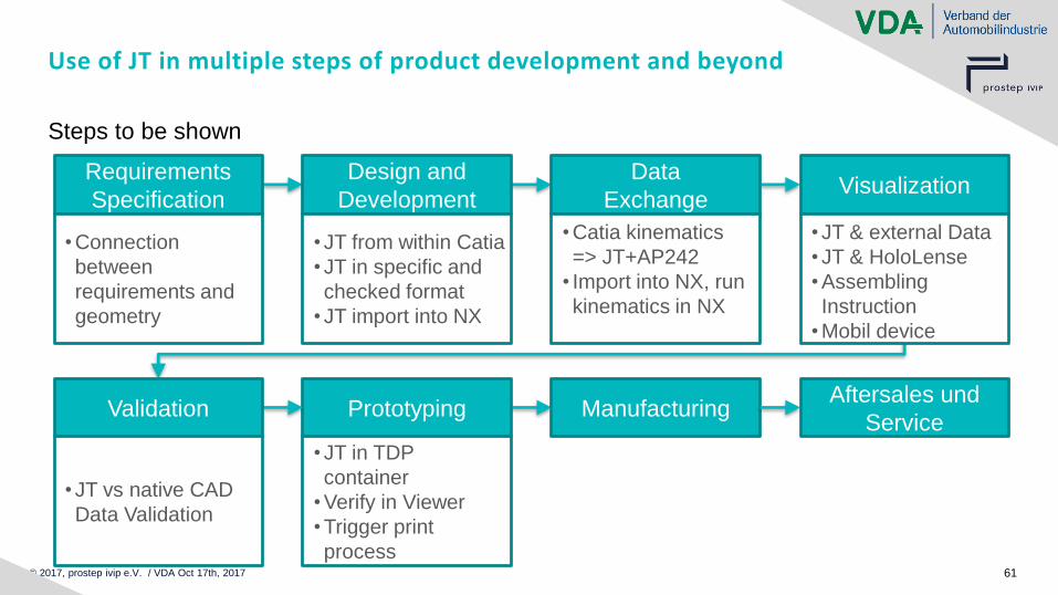
Use of JT in multiple steps of product development and beyond
Multiple Contributors, one Presenter for each track
© 2017, prostep ivip e.V. / VDA Oct 17th, 2017 3
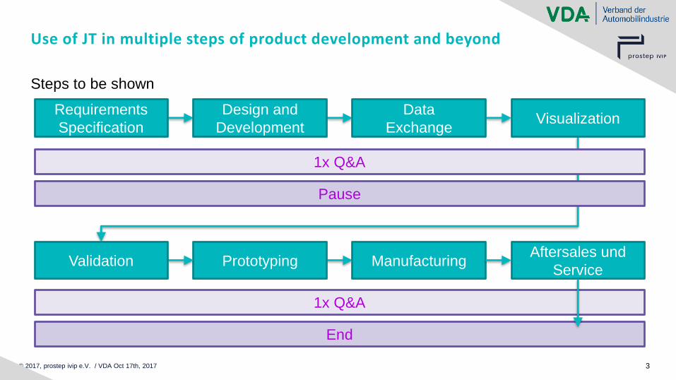
Use of JT in multiple steps of product development and beyond
Steps to be shown
Design and
Development
Data
ExchangeVisualization
Requirements
Specification
Prototyping ManufacturingAftersales und
ServiceValidation
1x Q&A
Pause
1x Q&A
End
© 2017, prostep ivip e.V. / VDA Oct 17th, 2017 4
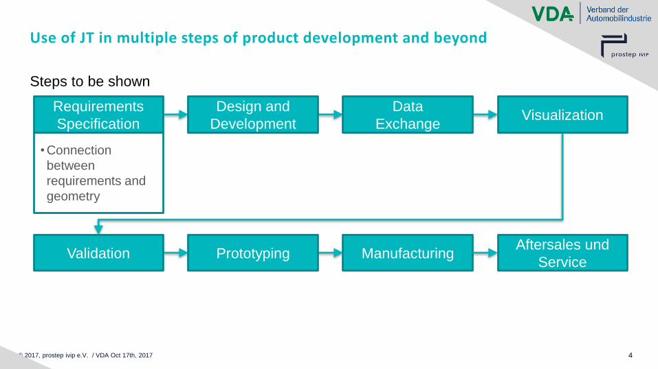
Use of JT in multiple steps of product development and beyond
Steps to be shown
Design and
Development
Data
ExchangeVisualization
Requirements
Specification
Prototyping ManufacturingAftersales und
ServiceValidation
• Connection
between
requirements and
geometry
© 2017, prostep ivip e.V. | :em AG JT-Day 2017, Renningen 5
Track 1:
Usage of JT in Requirements Engineering
How to connect JT and ReqIF?
Michael Kirsch
:em AG, Darmstadt
© 2017, prostep ivip e.V. | :em AG JT-Day 2017, Renningen 6
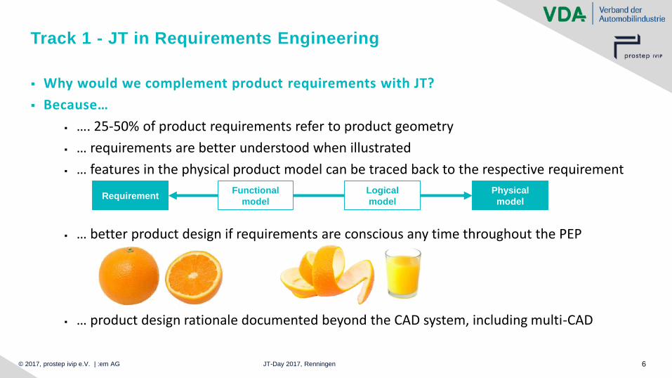
Track 1 - JT in Requirements Engineering
▪ Why would we complement product requirements with JT?
▪ Because…
▪ …. 25-50% of product requirements refer to product geometry
▪ … requirements are better understood when illustrated
▪ … features in the physical product model can be traced back to the respective requirement
▪ … better product design if requirements are conscious any time throughout the PEP
▪ … product design rationale documented beyond the CAD system, including multi-CAD
RequirementPhysical
model
Functional
model
Logical
model
© 2017, prostep ivip e.V. | :em AG JT-Day 2017, Renningen 7
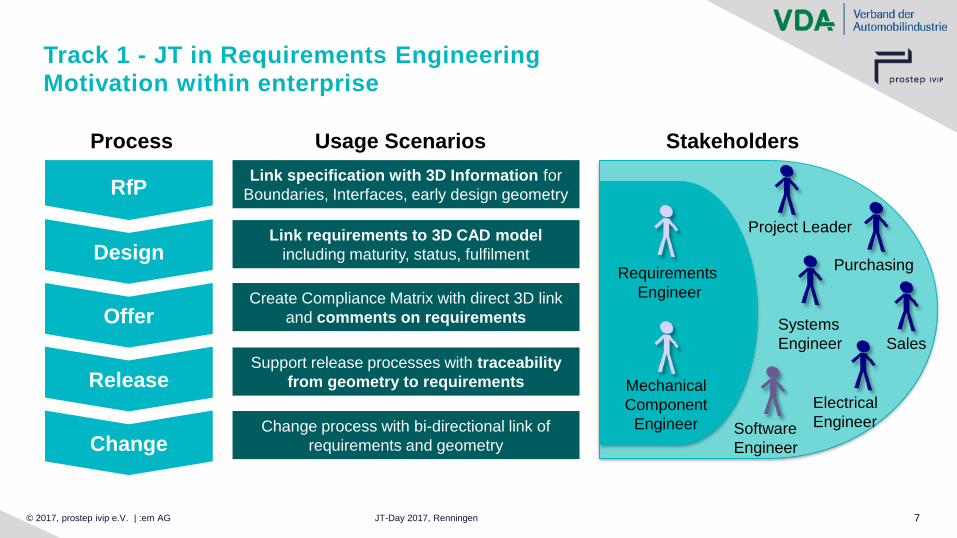
Track 1 - JT in Requirements Engineering
Motivation within enterprise
RfPLink specification with 3D Information for
Boundaries, Interfaces, early design geometry
DesignLink requirements to 3D CAD model
including maturity, status, fulfilment
Create Compliance Matrix with direct 3D link
and comments on requirements Offer
Support release processes with traceability
from geometry to requirementsRelease
Change process with bi-directional link of
requirements and geometryChange
StakeholdersUsage ScenariosProcess
Systems
Engineer
Software
Engineer
Electrical
Engineer
Project Leader
Purchasing
Sales
Requirements
Engineer
Mechanical
Component
Engineer
© 2017, prostep ivip e.V. | :em AG JT-Day 2017, Renningen 8
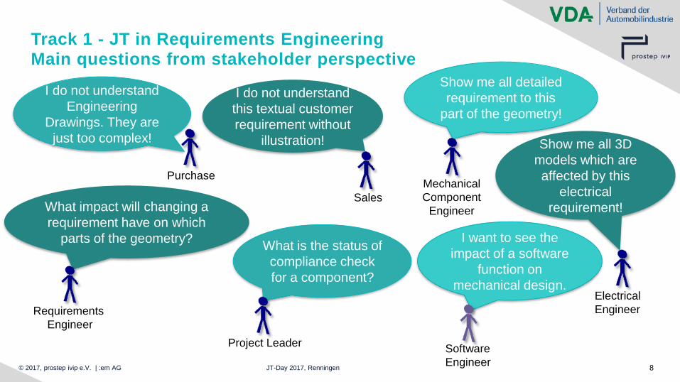
Track 1 - JT in Requirements Engineering
Main questions from stakeholder perspective
I do not understand
this textual customer
requirement without
illustration!
SalesWhat impact will changing a
requirement have on which
parts of the geometry?
Requirements
Engineer
What is the status of
compliance check
for a component?
Project Leader
Show me all detailed
requirement to this
part of the geometry!
Mechanical
Component
Engineer
I want to see the
impact of a software
function on
mechanical design.
Software
Engineer
Show me all 3D
models which are
affected by this
electrical
requirement!
Electrical
Engineer
I do not understand
Engineering
Drawings. They are
just too complex!
Purchase
© 2017, prostep ivip e.V. | :em AG JT-Day 2017, Renningen 9
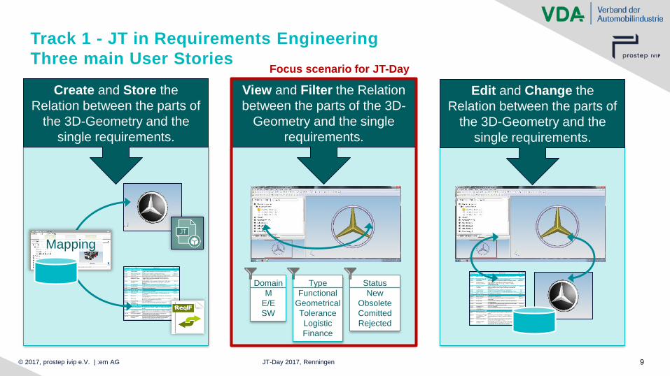
Track 1 - JT in Requirements Engineering
Three main User Stories
Create and Store the
Relation between the parts of
the 3D-Geometry and the
single requirements.
Mapping
View and Filter the Relation
between the parts of the 3D-
Geometry and the single
requirements.
Domain
M
E/E
SW
Type
Functional
Geometrical
Tolerance
Logistic
Finance
Status
New
Obsolete
Comitted
Rejected
Edit and Change the
Relation between the parts of
the 3D-Geometry and the
single requirements.
Focus scenario for JT-Day
© 2017, prostep ivip e.V. | :em AG JT-Day 2017, Renningen 10
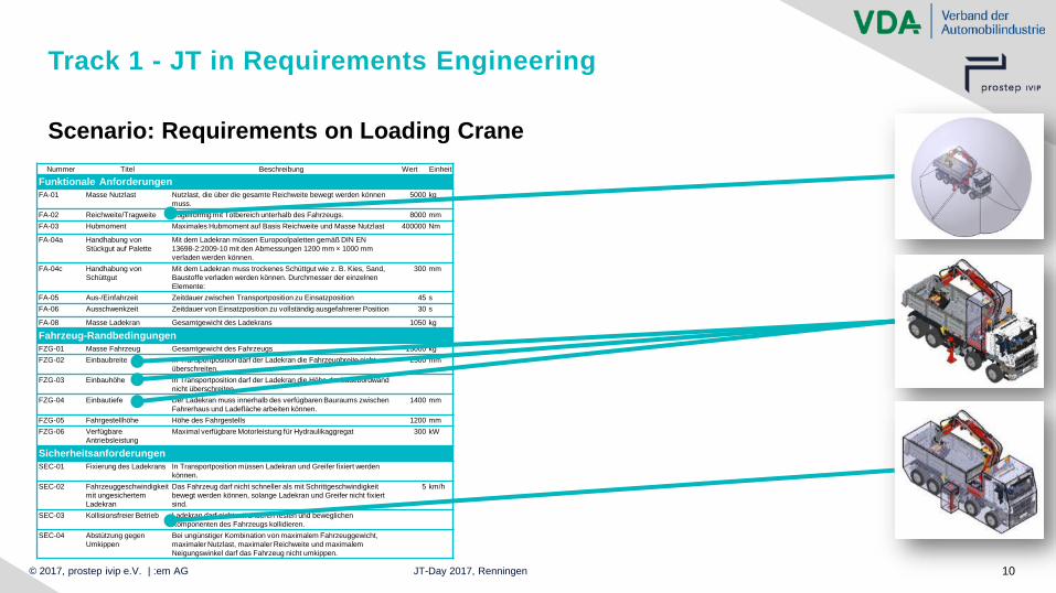
Scenario: Requirements on Loading Crane
Track 1 - JT in Requirements Engineering
Nummer Titel Beschreibung Wert Einheit
Funktionale Anforderungen
FA-01 Masse Nutzlast Nutzlast, die über die gesamte Reichweite bewegt werden können
muss.
5000 kg
FA-02 Reichweite/Tragweite Kugelförmig mit Totbereich unterhalb des Fahrzeugs. 8000 mm
FA-03 Hubmoment Maximales Hubmoment auf Basis Reichweite und Masse Nutzlast 400000 Nm
FA-04a Handhabung von
Stückgut auf Palette
Mit dem Ladekran müssen Europoolpaletten gemäß DIN EN
13698-2:2009-10 mit den Abmessungen 1200 mm × 1000 mm
verladen werden können.
FA-04c Handhabung von
Schüttgut
Mit dem Ladekran muss trockenes Schüttgut wie z. B. Kies, Sand,
Baustoffe verladen werden können. Durchmesser der einzelnen
Elemente:
300 mm
FA-05 Aus-/Einfahrzeit Zeitdauer zwischen Transportposition zu Einsatzposition 45 s
FA-06 Ausschwenkzeit Zeitdauer von Einsatzposition zu vollständig ausgefahrerer Position 30 s
FA-08 Masse Ladekran Gesamtgewicht des Ladekrans 1050 kg
Fahrzeug-Randbedingungen
FZG-01 Masse Fahrzeug Gesamtgewicht des Fahrzeugs 15000 kg
FZG-02 Einbaubreite In Transportposition darf der Ladekran die Fahrzeugbreite nicht
überschreiten.
2500 mm
FZG-03 Einbauhöhe In Transportposition darf der Ladekran die Höhe der Ladebordwand
nicht überschreiten.
FZG-04 Einbautiefe Der Ladekran muss innerhalb des verfügbaren Bauraums zwischen
Fahrerhaus und Ladefläche arbeiten können.
1400 mm
FZG-05 Fahrgestellhöhe Höhe des Fahrgestells 1200 mm
FZG-06 Verfügbare
Antriebsleistung
Maximal verfügbare Motorleistung für Hydraulikaggregat 300 kW
Sicherheitsanforderungen
SEC-01 Fixierung des Ladekrans In Transportposition müssen Ladekran und Greifer fixiert werden
können.
SEC-02 Fahrzeuggeschwindigkeit
mit ungesichertem
Ladekran
Das Fahrzeug darf nicht schneller als mit Schrittgeschwindigkeit
bewegt werden können, solange Ladekran und Greifer nicht fixiert
sind.
5 km/h
SEC-03 Kollisionsfreier Betrieb Ladekran darf nicht mit anderen festen und beweglichen
Komponenten des Fahrzeugs kollidieren.
SEC-04 Abstützung gegen
Umkippen
Bei ungünstiger Kombination von maximalem Fahrzeuggewicht,
maximaler Nutzlast, maximaler Reichweite und maximalem
Neigungswinkel darf das Fahrzeug nicht umkippen.
© 2017, prostep ivip e.V. | :em AG JT-Day 2017, Renningen 11
Track 1 - JT in Requirements Engineering
Interactive ReqIF and JT in Siemens PLM JT2Go/TCVis (Video)
© 2017, prostep ivip e.V. | :em AG JT-Day 2017, Renningen 12
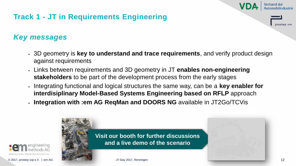
Track 1 - JT in Requirements Engineering
▪ 3D geometry is key to understand and trace requirements, and verify product design
against requirements
▪ Links between requirements and 3D geometry in JT enables non-engineering
stakeholders to be part of the development process from the early stages
▪ Integrating functional and logical structures the same way, can be a key enabler for
interdisiplinary Model-Based Systems Engineering based on RFLP approach
▪ Integration with :em AG ReqMan and DOORS NG available in JT2Go/TCVis
Key messages
Visit our booth for further discussions
and a live demo of the scenario
© 2017, prostep ivip e.V. / VDA Oct 17th, 2017 13
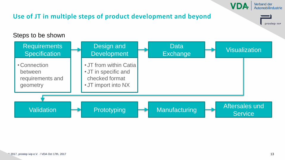
Use of JT in multiple steps of product development and beyond
Steps to be shown
Design and
Development
Data
ExchangeVisualization
Requirements
Specification
Prototyping ManufacturingAftersales und
ServiceValidation
• Connection
between
requirements and
geometry
• JT from within Catia
• JT in specific and
checked format
• JT import into NX

© 2017, prostep ivip e.V. / VDA Oct 17th, 2017 14
Track 2
Multi CAD Collaboration
Bastian Dachselt,
Siemens Industry Software GmbH

© 2017, prostep ivip e.V. / VDA Oct 17th, 2017 15
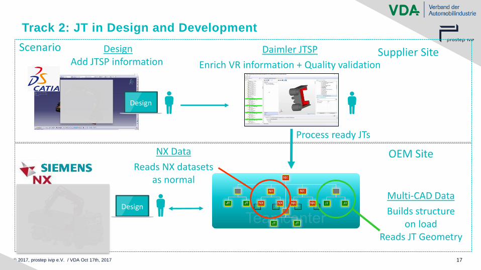
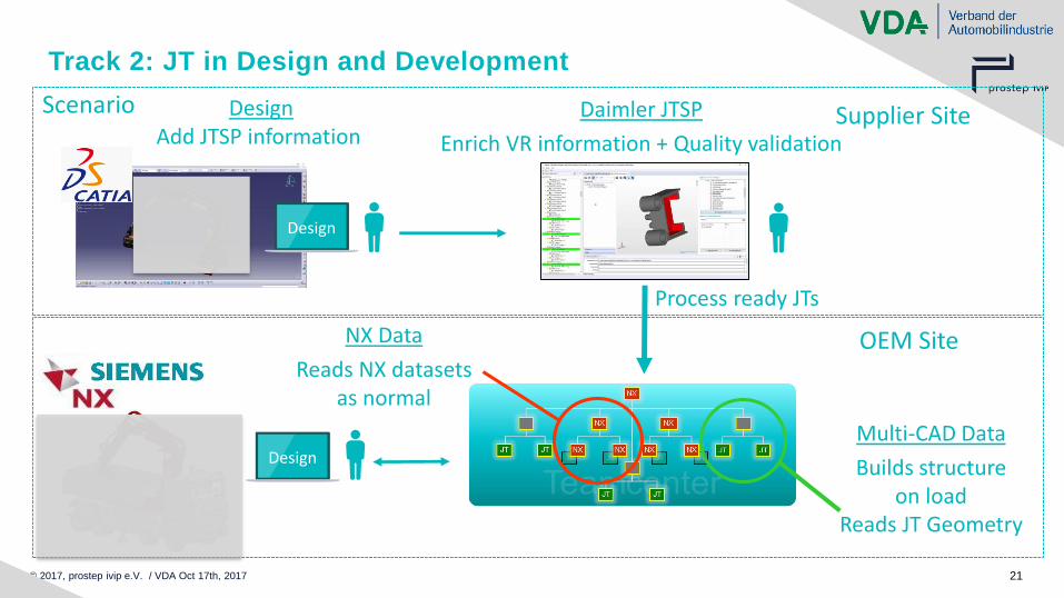
Track 2: JT in Design and Development
Scenario
Multi-CAD Data
Builds structure on load
Reads JT Geometry
NX Data
Reads NX datasets as normal
OEM Site
Design
Supplier SiteDaimler JTSP
Enrich VR information + Quality validation
DesignAdd JTSP information
Process ready JTs
Design
© 2017, prostep ivip e.V. / VDA Oct 17th, 2017 16
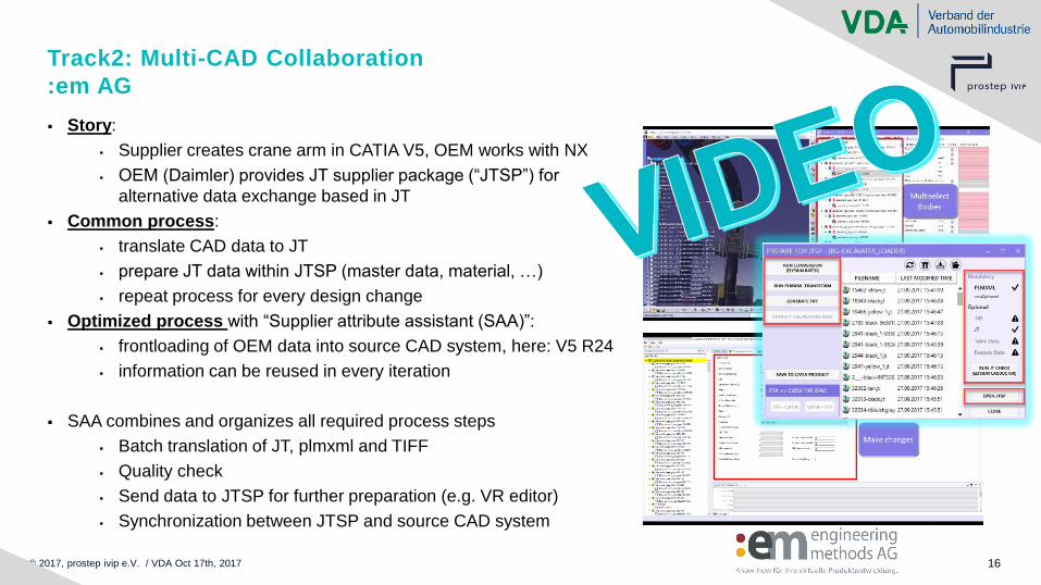
Track2: Multi-CAD Collaboration
:em AG
▪ Story:
▪ Supplier creates crane arm in CATIA V5, OEM works with NX
▪ OEM (Daimler) provides JT supplier package (“JTSP”) for
alternative data exchange based in JT
▪ Common process:
▪ translate CAD data to JT
▪ prepare JT data within JTSP (master data, material, …)
▪ repeat process for every design change
▪ Optimized process with “Supplier attribute assistant (SAA)”:
▪ frontloading of OEM data into source CAD system, here: V5 R24
▪ information can be reused in every iteration
▪ SAA combines and organizes all required process steps
▪ Batch translation of JT, plmxml and TIFF
▪ Quality check
▪ Send data to JTSP for further preparation (e.g. VR editor)
▪ Synchronization between JTSP and source CAD system
© 2017, prostep ivip e.V. / VDA Oct 17th, 2017 17
Track 2: JT in Design and Development
Scenario
Multi-CAD Data
Builds structure on load
Reads JT Geometry
NX Data
Reads NX datasets as normal
OEM Site
Design
Supplier SiteDaimler JTSP
Enrich VR information + Quality validation
DesignAdd JTSP information
Process ready JTs
Design
© 2017, prostep ivip e.V. / VDA Oct 17th, 2017 18
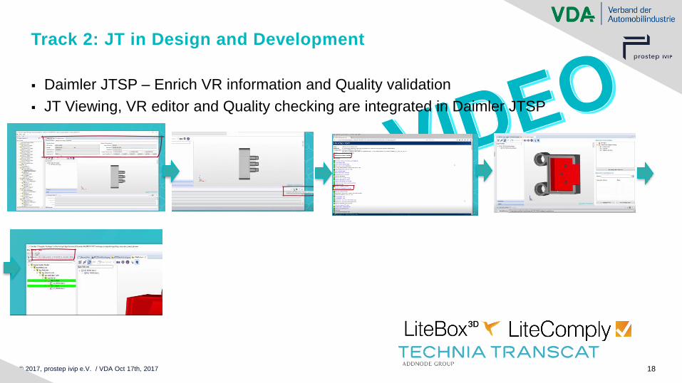
Track 2: JT in Design and Development
▪ Daimler JTSP – Enrich VR information and Quality validation
▪ JT Viewing, VR editor and Quality checking are integrated in Daimler JTSP

© 2017, prostep ivip e.V. / VDA Oct 17th, 2017 19
Track 2: JT in Design and Development
Scenario
Multi-CAD Data
Builds structure on load
Reads JT Geometry
NX Data
Reads NX datasets as normal
OEM Site
Design
Supplier SiteDaimler JTSP
Enrich VR information + Quality validation
DesignAdd JTSP information
Process ready JTs
Design
© 2017, prostep ivip e.V. / VDA Oct 17th, 2017 20
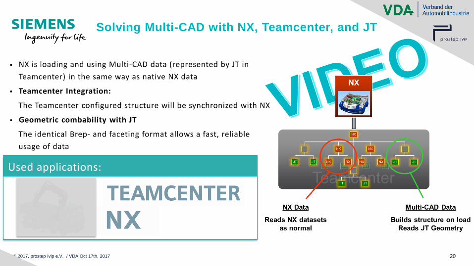
Solving Multi-CAD with NX, Teamcenter, and JT
Used applications:
▪ NX is loading and using Multi-CAD data (represented by JT in
Teamcenter) in the same way as native NX data
▪ Teamcenter Integration:
The Teamcenter configured structure will be synchronized with NX
▪ Geometric combability with JT
The identical Brep- and faceting format allows a fast, reliable
usage of data
© 2017, prostep ivip e.V. / VDA Oct 17th, 2017 21
Track 2: JT in Design and Development
Scenario
Multi-CAD Data
Builds structure on load
Reads JT Geometry
NX Data
Reads NX datasets as normal
OEM Site
Design
Supplier SiteDaimler JTSP
Enrich VR information + Quality validation
DesignAdd JTSP information
Process ready JTs
Design
© 2017, prostep ivip e.V. / VDA Oct 17th, 2017 22
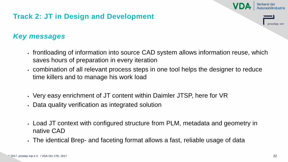
Track 2: JT in Design and Development
▪ frontloading of information into source CAD system allows information reuse, which
saves hours of preparation in every iteration
▪ combination of all relevant process steps in one tool helps the designer to reduce
time killers and to manage his work load
▪ Very easy enrichment of JT content within Daimler JTSP, here for VR
▪ Data quality verification as integrated solution
▪ Load JT context with configured structure from PLM, metadata and geometry in
native CAD
▪ The identical Brep- and faceting format allows a fast, reliable usage of data
Key messages
© 2017, prostep ivip e.V. / VDA Oct 17th, 2017 23
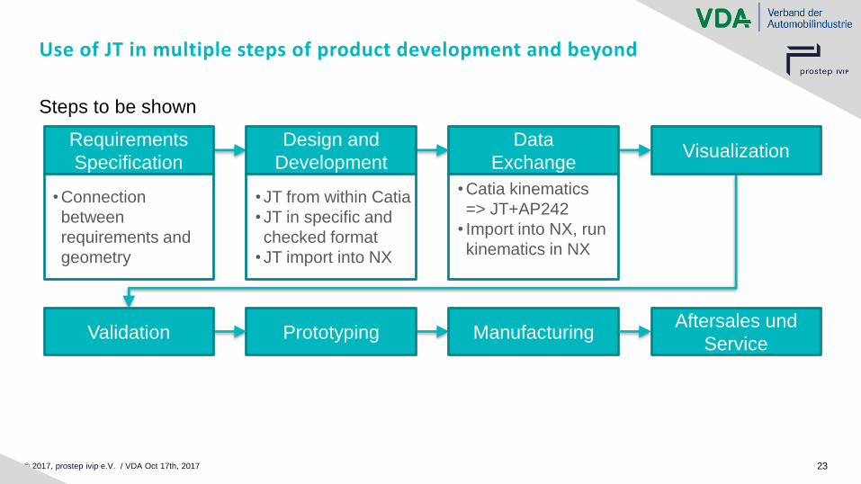
Use of JT in multiple steps of product development and beyond
Steps to be shown
Design and
Development
Data
ExchangeVisualization
Requirements
Specification
Prototyping ManufacturingAftersales und
ServiceValidation
• Connection
between
requirements and
geometry
• JT from within Catia
• JT in specific and
checked format
• JT import into NX
• Catia kinematics
=> JT+AP242
• Import into NX, run
kinematics in NX

© 2017, prostep ivip e.V. / VDA Oct 17th, 2017 24
Track 3
Data Exchange -Kinematics
Winfried Weber
T-Systems International GmbH
© 2017, prostep ivip e.V. / VDA Oct 17th, 2017 25
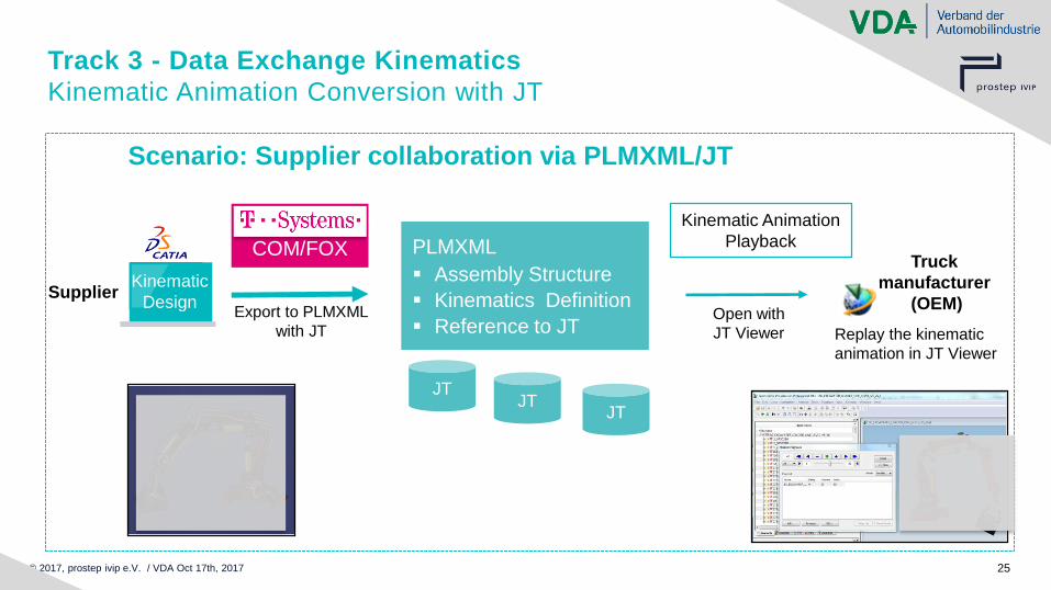
Track 3 - Data Exchange Kinematics
Kinematic Animation Conversion with JT
Kinematic
DesignExport to PLMXML
with JTOpen with
JT Viewer
Scenario: Supplier collaboration via PLMXML/JT
PLMXML
▪ Assembly Structure
▪ Kinematics Definition
▪ Reference to JT
JTJT
JT
COM/FOX
Replay the kinematic
animation in JT Viewer
Supplier
Truck
manufacturer
(OEM)
Kinematic Animation
Playback
© 2017, prostep ivip e.V. / VDA Oct 17th, 2017 26

© 2017, prostep ivip e.V. / VDA Oct 17th, 2017 27
Track 3 - Data Exchange Kinematics
Kinematic Animation Conversion with JT
Kinematic
DesignExport to PLMXML
with JTOpen with
JT Viewer
Scenario: Supplier collaboration via PLMXML/JT
PLMXML
▪ Assembly Structure
▪ Kinematics Definition
▪ Reference to JT
JTJT
JT
COM/FOX
Replay the kinematic
animation in JT Viewer
Supplier
Truck
manufacturer
(OEM)
Kinematic Animation
Playback
© 2017, prostep ivip e.V. / VDA Oct 17th, 2017 28
© 2017, prostep ivip e.V. / VDA Oct 17th, 2017 29
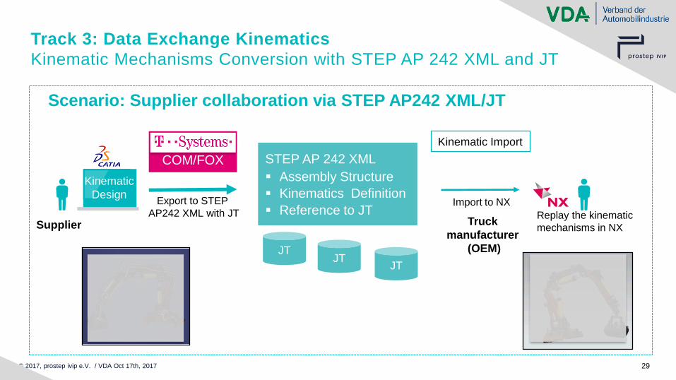
Track 3: Data Exchange Kinematics
Kinematic Mechanisms Conversion with STEP AP 242 XML and JT
Kinematic
DesignExport to STEP
AP242 XML with JTImport to NX
Scenario: Supplier collaboration via STEP AP242 XML/JT
STEP AP 242 XML
▪ Assembly Structure
▪ Kinematics Definition
▪ Reference to JT
JTJT
JT
COM/FOX
Replay the kinematic
mechanisms in NXSupplier Truck
manufacturer
(OEM)
Kinematic Import

© 2017, prostep ivip e.V. / VDA Oct 17th, 2017 30
© 2017, prostep ivip e.V. / VDA Oct 17th, 2017 31
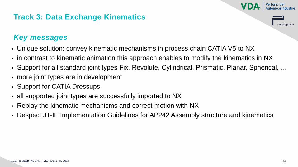
Track 3: Data Exchange Kinematics
▪ Unique solution: convey kinematic mechanisms in process chain CATIA V5 to NX
▪ in contrast to kinematic animation this approach enables to modify the kinematics in NX
▪ Support for all standard joint types Fix, Revolute, Cylindrical, Prismatic, Planar, Spherical, ...
▪ more joint types are in development
▪ Support for CATIA Dressups
▪ all supported joint types are successfully imported to NX
▪ Replay the kinematic mechanisms and correct motion with NX
▪ Respect JT-IF Implementation Guidelines for AP242 Assembly structure and kinematics
Key messages
© 2017, prostep ivip e.V. / VDA Oct 17th, 2017 32
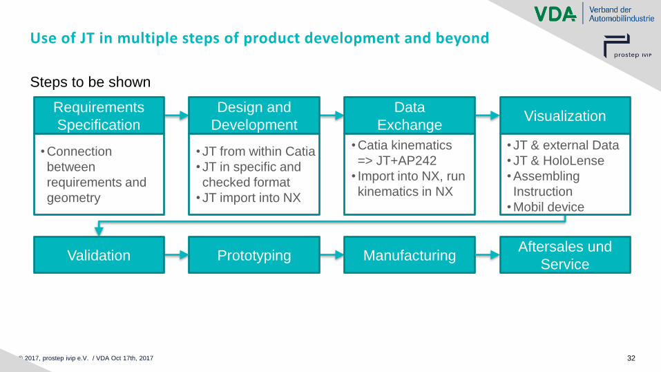
Use of JT in multiple steps of product development and beyond
Steps to be shown
Design and
Development
Data
ExchangeVisualization
Requirements
Specification
Prototyping ManufacturingAftersales und
ServiceValidation
• Connection
between
requirements and
geometry
• JT from within Catia
• JT in specific and
checked format
• JT import into NX
• Catia kinematics
=> JT+AP242
• Import into NX, run
kinematics in NX
• JT & external Data
• JT & HoloLense
• Assembling
Instruction
• Mobil device

© 2017, prostep ivip e.V. / VDA Oct 17th, 2017 33
Track 4
Visualization
Sebastian Schwarz
NetAllied Systems GmbH
© 2017, prostep ivip e.V. / VDA 17 November 2017 Thema: JT-Day 2017, Renningen 34
Track 4: JT for Visualization
Visualization is one of the most important use cases for JT
Today demonstrating five vendors’ solutions
© 2017, prostep ivip e.V. / VDA 17 November 2017 Thema: JT-Day 2017, Renningen 35
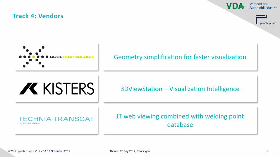
Track 4: Vendors
Geometry simplification for faster visualization
3DViewStation – Visualization Intelligence
JT web viewing combined with welding point database
© 2017, prostep ivip e.V. / VDA 17 November 2017 Thema: JT-Day 2017, Renningen 36
Track 4: Vendors
Customized viewing solutions
Visualization using Microsoft Hololens
© 2017, prostep ivip e.V. / VDA 17 November 2017 Thema: JT-Day 2017, Renningen 37
Track 4: Gaining performance of CAD and JT files byCoreTechnologie 3D_Evolution
▪ Story:
▪ Efficient geometry simplification and data reduction of the Lego Daimler Truck in only two steps of preprocessing

© 2017, prostep ivip e.V. / VDA 17 November 2017 Thema: JT-Day 2017, Renningen 38
© 2017, prostep ivip e.V. / VDA 17 November 2017 Thema: JT-Day 2017, Renningen 39
Track 4: Gaining Performance of CAD and JT Files byCoreTechnologie 3D_Evolution
▪ Benefits:
▪ Batch process based on scripts (process in less minutes)
▪ Multi-CAD support for import and export of JT, NX, V5, etc. for further processes as DMU and VR
© 2017, prostep ivip e.V. / VDA 17 November 2017 Thema: JT-Day 2017, Renningen 40
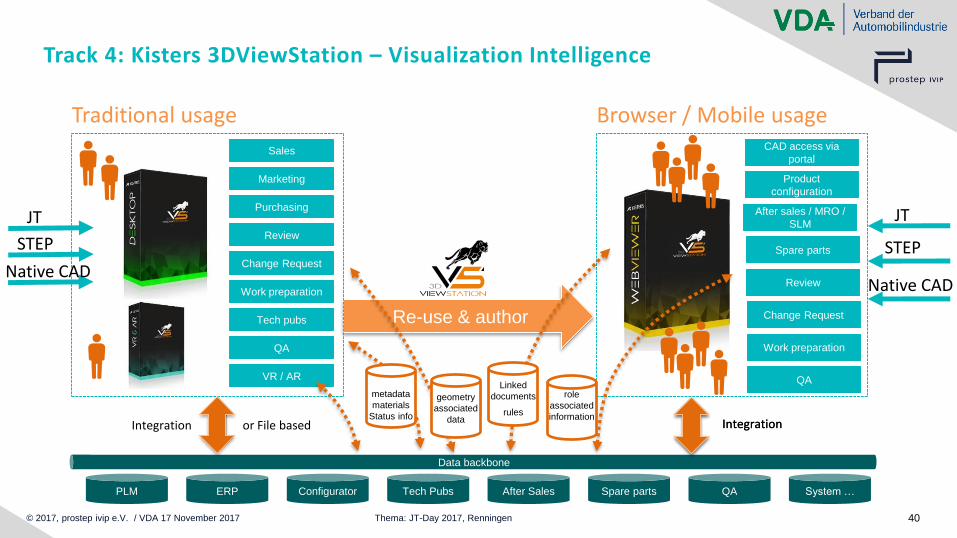
Re-use & author
Review
Browser / Mobile usage
Spare parts
Product
configuration
After sales / MRO /
SLM
CAD access via
portal
Change Request
Work preparation
QA
JT
STEP
Native CAD
Track 4: Kisters 3DViewStation – Visualization Intelligence
JT
Marketing
Traditional usage
STEP
Native CADWork preparation
Review
Change Request
Tech pubs
Sales
Purchasing
QA
VR / AR
QA System …
Data backbone
PLM ERP Tech Pubs Spare parts
Integration or File based
Configurator After Sales
IntegrationIntegration
geometry
associated
data
metadata
materials
Status info
role
associated
information
Linked
documents
rules

© 2017, prostep ivip e.V. / VDA 17 November 2017 Thema: JT-Day 2017, Renningen 41
© 2017, prostep ivip e.V. / VDA 17 November 2017 Thema: JT-Day 2017, Renningen 42
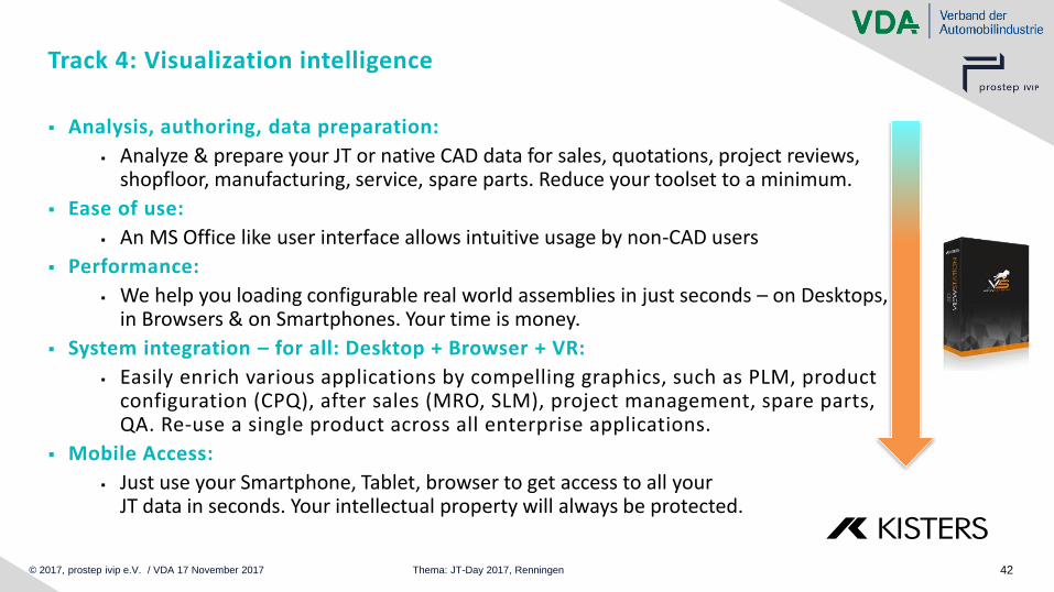
▪ Analysis, authoring, data preparation:
▪ Analyze & prepare your JT or native CAD data for sales, quotations, project reviews, shopfloor, manufacturing, service, spare parts. Reduce your toolset to a minimum.
▪ Ease of use:
▪ An MS Office like user interface allows intuitive usage by non-CAD users
▪ Performance:
▪ We help you loading configurable real world assemblies in just seconds – on Desktops, in Browsers & on Smartphones. Your time is money.
▪ System integration – for all: Desktop + Browser + VR:
▪ Easily enrich various applications by compelling graphics, such as PLM, product configuration (CPQ), after sales (MRO, SLM), project management, spare parts, QA. Re-use a single product across all enterprise applications.
▪ Mobile Access:
▪ Just use your Smartphone, Tablet, browser to get access to all your JT data in seconds. Your intellectual property will always be protected.
Track 4: Visualization intelligence
© 2017, prostep ivip e.V. / VDA 17 November 2017 Thema: JT-Day 2017, Renningen 43
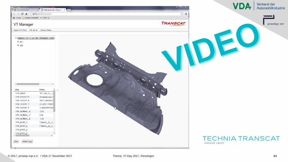
Track 4: Combined Visualization of JT and external data sources
▪ Story:
▪ JT Web viewing combined with welding database
© 2017, prostep ivip e.V. / VDA 17 November 2017 Thema: JT-Day 2017, Renningen 44
© 2017, prostep ivip e.V. / VDA 17 November 2017 Thema: JT-Day 2017, Renningen 45
Track 4: Combined Visualization of JT and external data sources
▪ Benefits:
▪ No native CAD files or expensive CAD workstation required
▪ Easy to use and mobile device ready application
© 2017, prostep ivip e.V. / VDA 17 November 2017 Thema: JT-Day 2017, Renningen 46
Track 4: NetAllied - Story
▪ Interactive visual workplace for Pre-Series manufacturing at Volkswagen
▪ Replacing traditional printed 2D drawings with an interactive, easy-to-use 3D visualization
▪ Fastening information is stored in SAP, 3D parts were available in JT
© 2017, prostep ivip e.V. / VDA 17 November 2017 Thema: JT-Day 2017, Renningen 47
© 2017, prostep ivip e.V. / VDA 17 November 2017 Thema: JT-Day 2017, Renningen 48
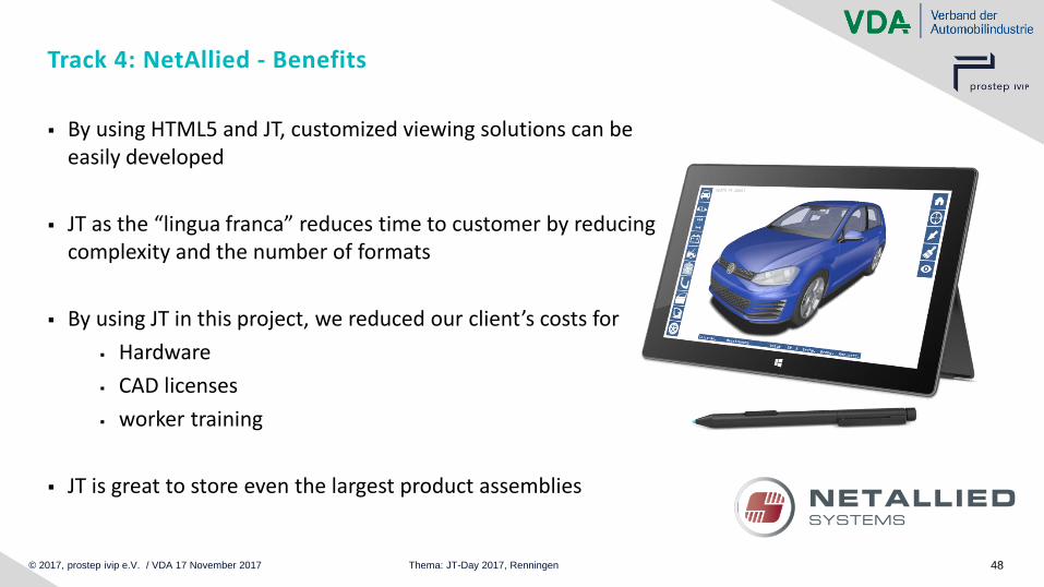
Track 4: NetAllied - Benefits
▪ By using HTML5 and JT, customized viewing solutions can be easily developed
▪ JT as the “lingua franca” reduces time to customer by reducing complexity and the number of formats
▪ By using JT in this project, we reduced our client’s costs for
▪ Hardware
▪ CAD licenses
▪ worker training
▪ JT is great to store even the largest product assemblies
© 2017, prostep ivip e.V. / VDA 17 November 2017 Thema: JT-Day 2017, Renningen 49
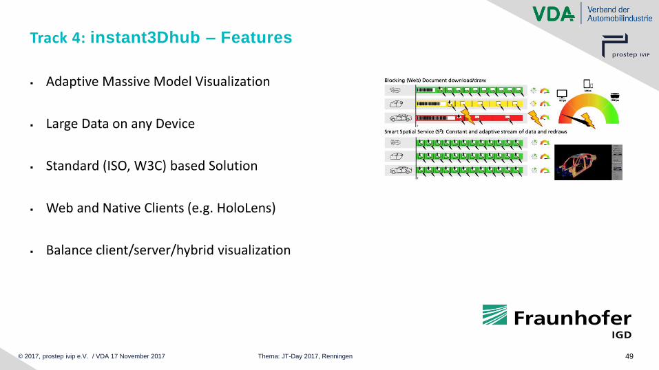
Track 4: instant3Dhub – Features
▪ Adaptive Massive Model Visualization
▪ Large Data on any Device
▪ Standard (ISO, W3C) based Solution
▪ Web and Native Clients (e.g. HoloLens)
▪ Balance client/server/hybrid visualization

© 2017, prostep ivip e.V. / VDA 17 November 2017 Thema: JT-Day 2017, Renningen 50
© 2017, prostep ivip e.V. / VDA 17 November 2017 Thema: JT-Day 2017, Renningen 51
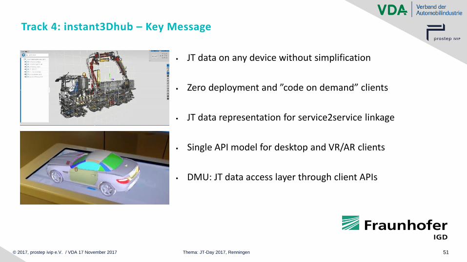
Track 4: instant3Dhub – Key Message
▪ JT data on any device without simplification
▪ Zero deployment and ”code on demand” clients
▪ JT data representation for service2service linkage
▪ Single API model for desktop and VR/AR clients
▪ DMU: JT data access layer through client APIs
© 2017, prostep ivip e.V. / VDA 17 November 2017 Thema: JT-Day 2017, Renningen 52
Track 4: Summary
✓ OpennessStandardized and supported by prostep ivip, VDA, ISO,
✓ Performancesmall size, fastest rendering
✓ Availabilitymillions of files available throughout whole product lifecycle
✓ Flexibilitycan be integrated into existing and new applications
✓ Robustnumerous proven workflows
Visualization is the core discipline of JT!
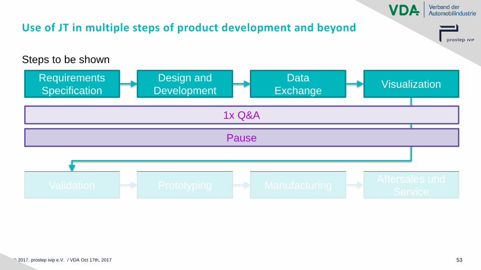
© 2017, prostep ivip e.V. / VDA Oct 17th, 2017 53
Use of JT in multiple steps of product development and beyond
Steps to be shown
Design and
Development
Data
ExchangeVisualization
Requirements
Specification
Prototyping ManufacturingAftersales und
ServiceValidation
1x Q&A
Pause

© 2017, prostep ivip e.V. / VDA Oct 17th, 2017 54
JT Scenarios
8 Tracks of JT usage along the value chain
Multiple Presenters
Moderation
Alfred Eckrich, Bosch GmbHStefan Just, Prostep AG

© 2017, prostep ivip e.V. / VDA Oct 17th, 2017 55
Use of JT in multiple steps of product development and beyond
Steps to be shown
Design and
Development
Data
ExchangeVisualization
Requirements
Specification
Prototyping ManufacturingAftersales und
ServiceValidation
1x Q&A
Pause
1x Q&A
End
© 2017, prostep ivip e.V. / VDA Oct 17th, 2017 56
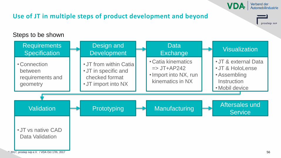
Use of JT in multiple steps of product development and beyond
Steps to be shown
Design and
Development
Data
ExchangeVisualization
Requirements
Specification
Prototyping ManufacturingAftersales und
ServiceValidation
• Connection
between
requirements and
geometry
• JT from within Catia
• JT in specific and
checked format
• JT import into NX
• Catia kinematics
=> JT+AP242
• Import into NX, run
kinematics in NX
• JT & external Data
• JT & HoloLense
• Assembling
Instruction
• Mobil device
• JT vs native CAD
Data Validation

© 2017, prostep ivip e.V. / VDA Oct 17th, 2017 57
Track 5
Validation
Alexander Christ
Elysium Europe SARL
© 2017, prostep ivip e.V. / VDA Oct 17th, 2017 58
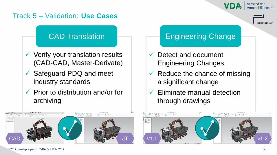
Track 5 – Validation: Use Cases
✓ Verify your translation results
(CAD-CAD, Master-Derivate)
✓ Safeguard PDQ and meet
industry standards
✓ Prior to distribution and/or for
archiving
CAD Translation
✓ Detect and document
Engineering Changes
✓ Reduce the chance of missing
a significant change
✓ Eliminate manual detection
through drawings
Engineering Change
CAD JT v1.1 v1.2
© 2017, prostep ivip e.V. / VDA Oct 17th, 2017 59
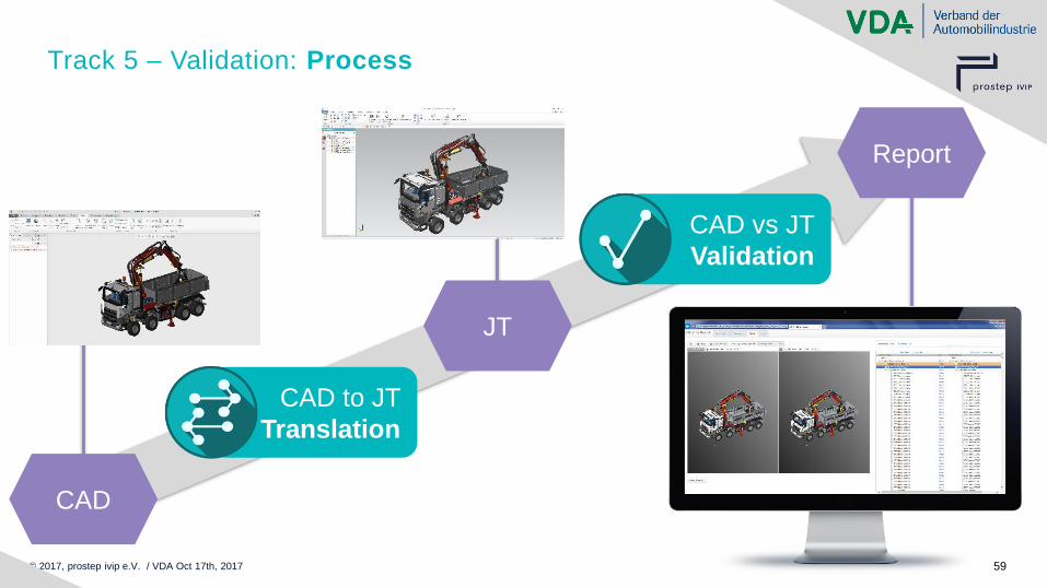
Track 5 – Validation: Process
CAD
JT
Report
CAD to JT
Translation
CAD vs JT
Validation
© 2017, prostep ivip e.V. / VDA Oct 17th, 2017 60
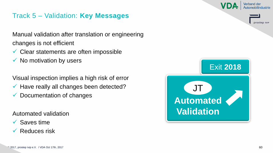
Track 5 – Validation: Key Messages
Manual validation after translation or engineering
changes is not efficient
✓ Clear statements are often impossible
✓ No motivation by users
Visual inspection implies a high risk of error
✓ Have really all changes been detected?
✓ Documentation of changes
Automated validation
✓ Saves time
✓ Reduces risk
Exit 2018
Automated
Validation
JT
© 2017, prostep ivip e.V. / VDA Oct 17th, 2017 61
Use of JT in multiple steps of product development and beyond
Steps to be shown
Design and
Development
Data
ExchangeVisualization
Requirements
Specification
Prototyping ManufacturingAftersales und
ServiceValidation
• Connection
between
requirements and
geometry
• JT from within Catia
• JT in specific and
checked format
• JT import into NX
• Catia kinematics
=> JT+AP242
• Import into NX, run
kinematics in NX
• JT & external Data
• JT & HoloLense
• Assembling
Instruction
• Mobil device
• JT vs native CAD
Data Validation
• JT in TDP
container
• Verify in Viewer
• Trigger print
process

© 2017, prostep ivip e.V. / VDA Oct 17th, 2017 62
Track 6
Prototyping
Alexander Christ,
Elysium Europe SARL
© 2017, prostep ivip e.V. / VDA Oct 17th, 2017 63
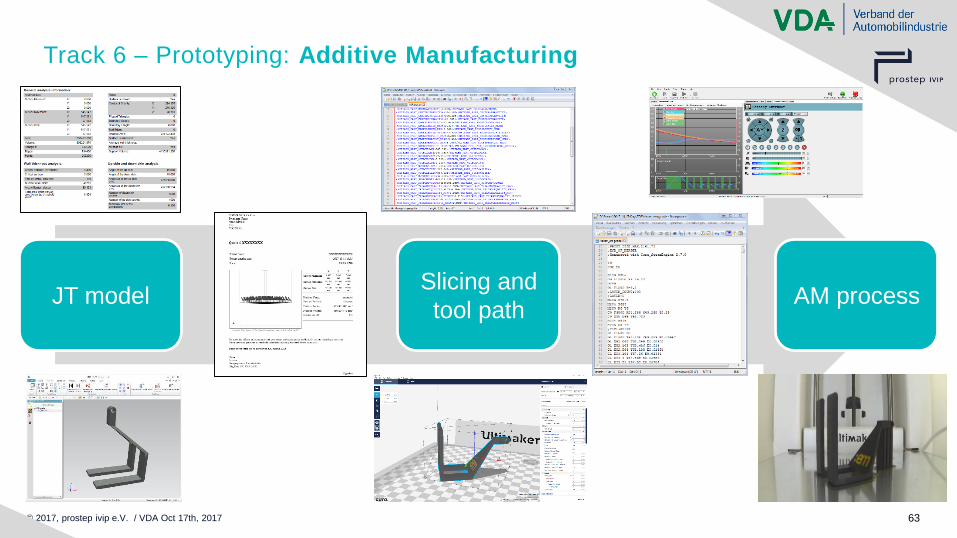
Track 6 – Prototyping: Additive Manufacturing
JT modelSlicing and
tool pathAM process
© 2017, prostep ivip e.V. / VDA Oct 17th, 2017 64
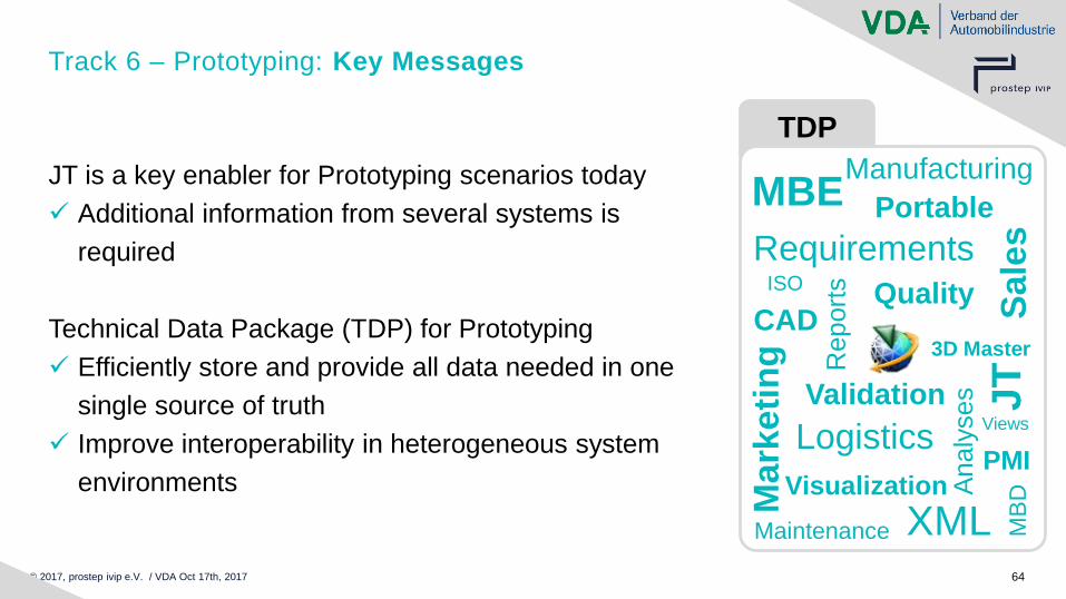
TDP
Track 6 – Prototyping: Key Messages
JT is a key enabler for Prototyping scenarios today
✓ Additional information from several systems is
required
Technical Data Package (TDP) for Prototyping
✓ Efficiently store and provide all data needed in one
single source of truth
✓ Improve interoperability in heterogeneous system
environments
Sale
s
CAD
Manufacturing
Logistics
Maintenance
Ma
rke
tin
g
MBE
Validation
MB
D
3D Master
Requirements
XMLVisualization
Report
s
Analy
se
s
PMI
Views
JT
Portable
QualityISO
© 2017, prostep ivip e.V. / VDA Oct 17th, 2017 65
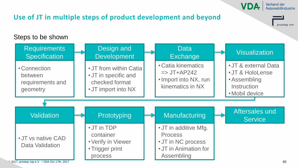
Use of JT in multiple steps of product development and beyond
Steps to be shown
Design and
Development
Data
ExchangeVisualization
Requirements
Specification
Prototyping ManufacturingAftersales und
ServiceValidation
• Connection
between
requirements and
geometry
• JT from within Catia
• JT in specific and
checked format
• JT import into NX
• Catia kinematics
=> JT+AP242
• Import into NX, run
kinematics in NX
• JT & external Data
• JT & HoloLense
• Assembling
Instruction
• Mobil device
• JT vs native CAD
Data Validation
• JT in TDP
container
• Verify in Viewer
• Trigger print
process
• JT in additive Mfg.
Process
• JT in NC process
• JT in Animation for
Assembling

© 2017, prostep ivip e.V. / VDA Oct 17th, 2017 66
Track 7
Manufacturing
Arnd Feye
Technia Transcat GmbH
© 2017, prostep ivip e.V. / VDA Oct 17th, 2017 67
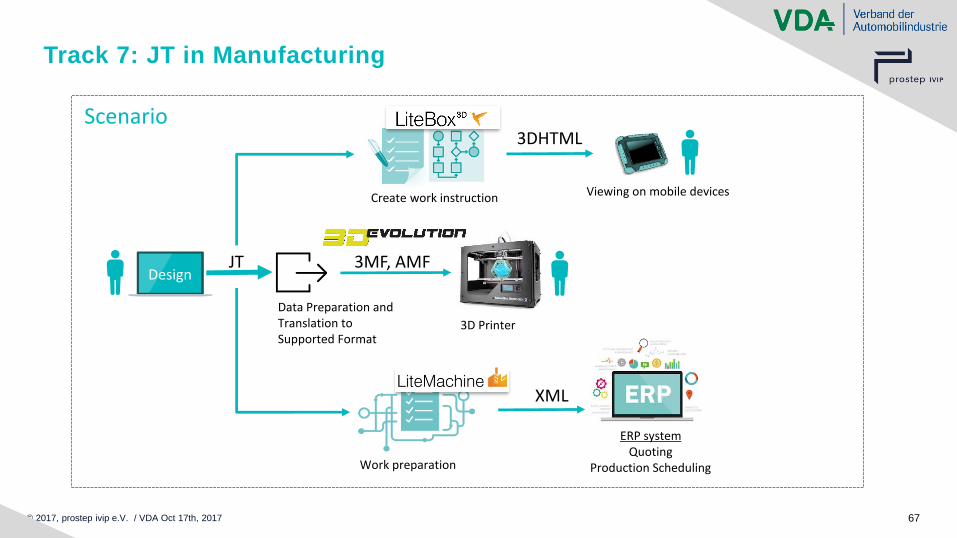
Track 7: JT in Manufacturing
DesignJT
Scenario
Data Preparation and Translation toSupported Format
3MF, AMF
3D Printer
Viewing on mobile devicesCreate work instruction
3DHTML
Work preparation
ERP systemQuoting
Production Scheduling
XML
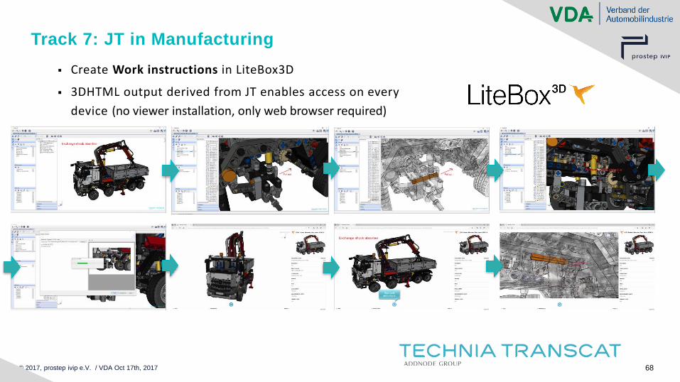
© 2017, prostep ivip e.V. / VDA Oct 17th, 2017 68
▪ Create Work instructions in LiteBox3D
▪ 3DHTML output derived from JT enables access on every
device (no viewer installation, only web browser required)
Track 7: JT in Manufacturing
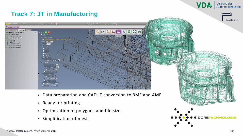
© 2017, prostep ivip e.V. / VDA Oct 17th, 2017 69
▪ Data preparation and CAD JT conversion to 3MF and AMF
▪ Ready for printing
▪ Optimization of polygons and file size
▪ Simplification of mesh
Track 7: JT in Manufacturing
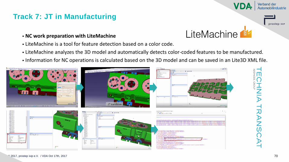
© 2017, prostep ivip e.V. / VDA Oct 17th, 2017 70
▪ NC work preparation with LiteMachine
▪ LiteMachine is a tool for feature detection based on a color code.
▪ LiteMachine analyzes the 3D model and automatically detects color-coded features to be manufactured.
▪ Information for NC operations is calculated based on the 3D model and can be saved in an Lite3D XML file.
Track 7: JT in Manufacturing
© 2017, prostep ivip e.V. / VDA Oct 17th, 2017 71
Track 7: JT in Manufacturing
Key Messages:
▪ Lightweight JTs are easy to create, enrich and consume
▪ 3DHTML output derived from JT enables access on every device (no viewer installation, only web browser required)
▪ Optimization with re-tesselation of JT files and export as 3MF or AMF for Additive Manufacturing
▪ From Multi-CAD workflow to unified process using JT as process format
© 2017, prostep ivip e.V. / VDA Oct 17th, 2017 72
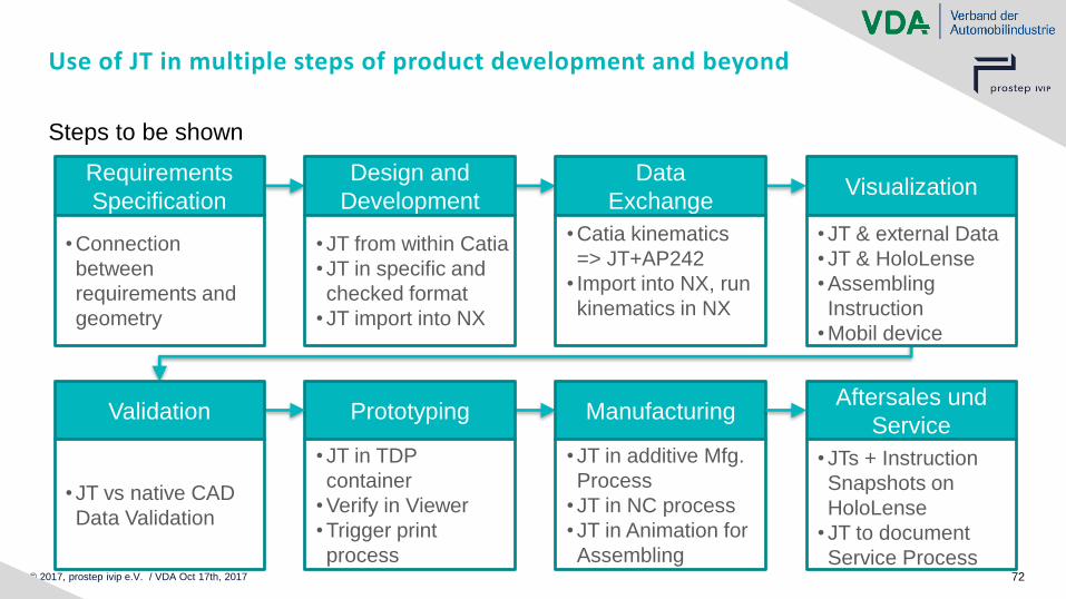
Use of JT in multiple steps of product development and beyond
Steps to be shown
Design and
Development
Data
ExchangeVisualization
Requirements
Specification
Prototyping ManufacturingAftersales und
ServiceValidation
• Connection
between
requirements and
geometry
• JT from within Catia
• JT in specific and
checked format
• JT import into NX
• Catia kinematics
=> JT+AP242
• Import into NX, run
kinematics in NX
• JT & external Data
• JT & HoloLense
• Assembling
Instruction
• Mobil device
• JT vs native CAD
Data Validation
• JT in TDP
container
• Verify in Viewer
• Trigger print
process
• JT in additive Mfg.
Process
• JT in NC process
• JT in Animation for
Assembling
• JTs + Instruction
Snapshots on
HoloLense
• JT to document
Service Process

© 2017, prostep ivip e.V. / VDA Oct 17th, 2017 73
Track 8
Aftersales & Service
David Shackleton
Theorem Solutions
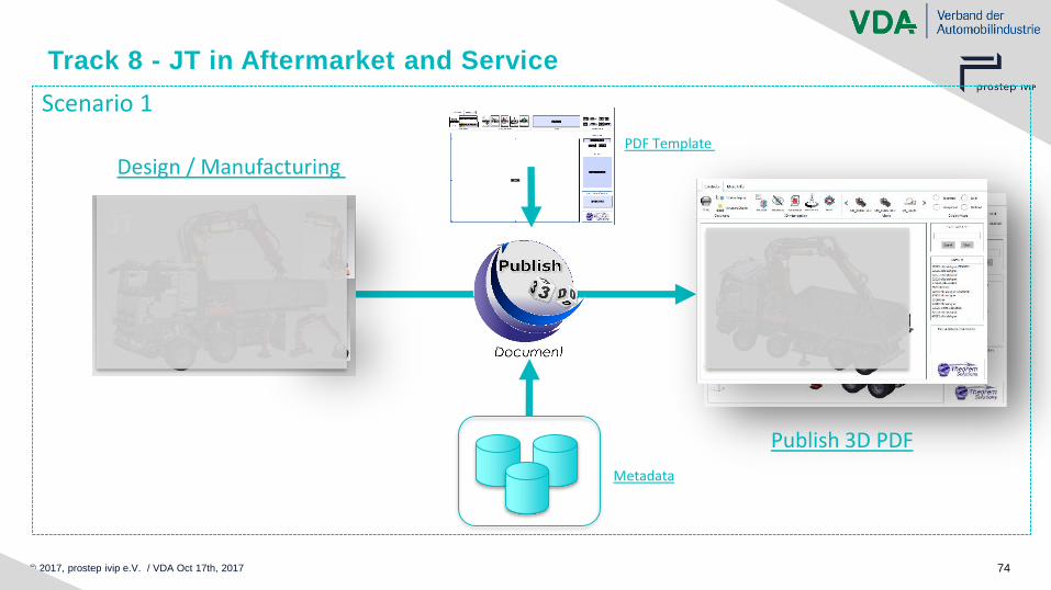
© 2017, prostep ivip e.V. / VDA Oct 17th, 2017 74
Track 8 - JT in Aftermarket and Service
Scenario 1
Design / Manufacturing
Publish 3D PDF
Metadata
JT
JT
PDF Template
© 2017, prostep ivip e.V. / VDA Oct 17th, 2017 75
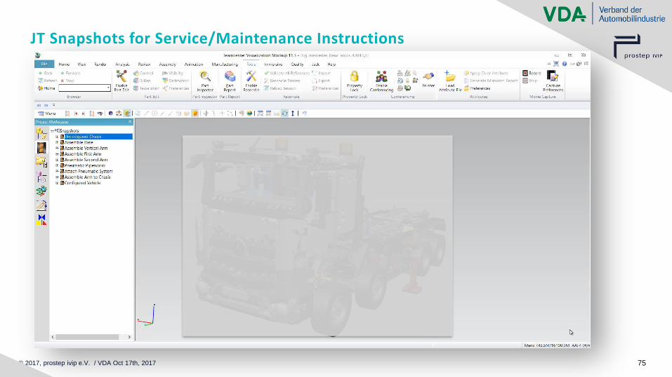
JT Snapshots for Service/Maintenance Instructions
© 2017, prostep ivip e.V. / VDA Oct 17th, 2017 76
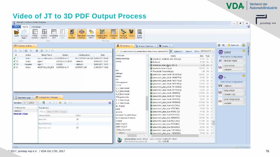
Video of JT to 3D PDF Output Process
© 2017, prostep ivip e.V. / VDA Oct 17th, 2017 77
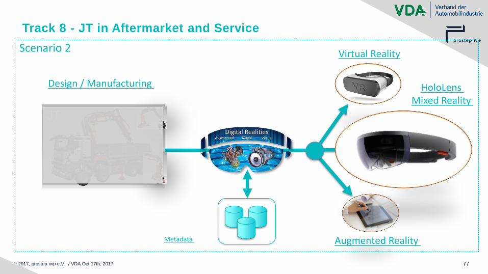
Track 8 - JT in Aftermarket and Service
Scenario 2
Design / Manufacturing
Metadata
JT
HoloLens Mixed Reality
Virtual Reality
Augmented Reality
© 2017, prostep ivip e.V. / VDA Oct 17th, 2017 78
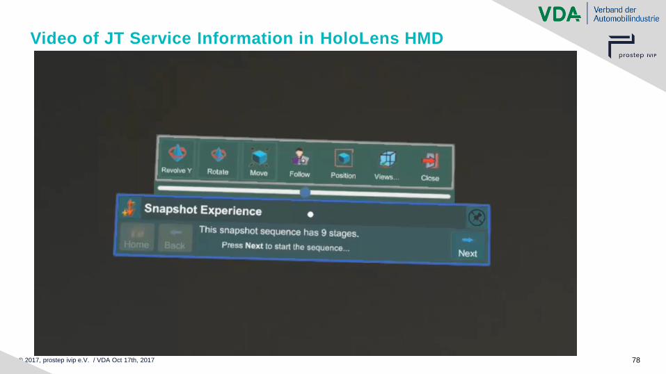
Video of JT Service Information in HoloLens HMD
© 2017, prostep ivip e.V. / VDA Oct 17th, 2017 79
Track 8 - JT in Aftermarket and Service
▪ Rich and intelligent output created from simple user interactions underpinned by
use of standard JT data
▪ Using JT data allows greater flexibility in delivering the best method of interacting
with the output for the appropriate use case
▪ Unique Digital Reality user experiences directly accessing JT Design &
Manufacturing information
Key messages
© 2017, prostep ivip e.V. / VDA Oct 17th, 2017 80
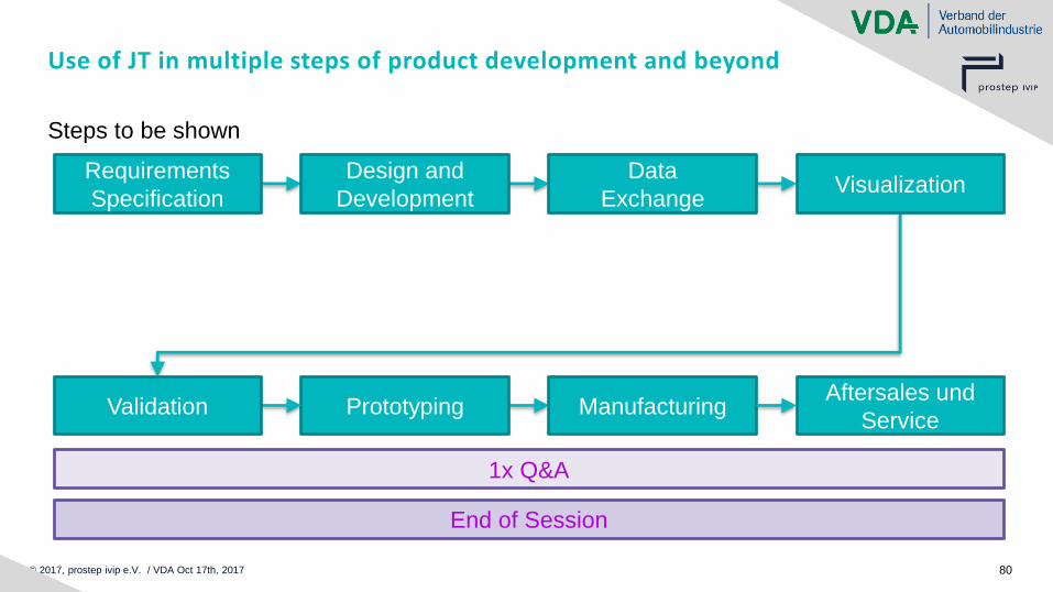
Use of JT in multiple steps of product development and beyond
Steps to be shown
Design and
Development
Data
ExchangeVisualization
Requirements
Specification
Prototyping ManufacturingAftersales und
ServiceValidation
1x Q&A
End of Session


