27
Website: www.datalogger.co.in , [email protected] , [email protected] , Tel. No. +91-79-32900400 ( 1 ) KH300AG/Paperless Recorder Manual Version V2.6
Website: www.datalogger.co.in, [email protected], [email protected], Tel. No. +91-79-32900400 ( 1 )
KH300AG/Paperless Recorder
Manual
Version V2.6
Website: www.datalogger.co.in, [email protected], [email protected], Tel. No. +91-79-32900400 ( 2 )
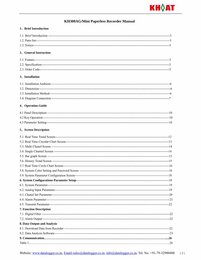
KH300AG/Mini Paperless Recorder Manual
1、Brief Introduction
1.1. Brief Introduction ----------------------------------------------------------------------------------------------------------------------3 1.2. Parts list----------------------------------------------------------------------------------------------------------------------------------3 1.3. Notice------------------------------------------------------------------------------------------------------------------------------------3
2、General Instruction
2.1. Feature-----------------------------------------------------------------------------------------------------------------------------------3 2.2. Specification----------------------------------------------------------------------------------------------------------------------------3 2.3. Order Code------------------------------------------------------------------------------------------------------------------------------5
3、Installation
3.1. Installation Ambient--------------------------------------------------------------------------------------------------------------------6 3.2. Dimension--------------------------------------------------------------------------------------------------------------------------------6 3.3. Installation Method---------------------------------------------------------------------------------------------------------------------6 3.4. Diagram Connection ------------------------------------------------------------------------------------------------------------------7
4、Operation Guide
4.1 Panel Description-----------------------------------------------------------------------------------------------------------------------10 4.2 Key Operation---------------------------------------------------------------------------------------------------------------------------10 4.3 Parameter Setting-----------------------------------------------------------------------------------------------------------------------10
5、Screen Description
5.1. Real Time Trend Screen--------------------------------------------------------------------------------------------------------------12 5.2. Real Time Circular Chart Screen----------------------------------------------------------------------------------------------------13 5.3. Multi Chanel Screen ------------------------------------------------------------------------------------------------------------------14 5.4. Single Channel Screen ---------------------------------------------------------------------------------------------------------------14 5.5. Bar graph Screen ----------------------------------------------------------------------------------------------------------------------15 5.6. History Trend Screen -----------------------------------------------------------------------------------------------------------------15 5.7. Real Time Circle Chart Screen-------------------------------------------------------------------------------------------------------16 5.8. System Color Setting and Password Screen ---------------------------------------------------------------------------------------16 5.9. System Parameter Configuration Screen-------------------------------------------------------------------------------------------18 6. System Configurations Parameter Setup------------------------------------------------------------------------------------------18 6.1. System Parameter----------------------------------------------------------------------------------------------------------------------19 6.2. Analog Input Parameter---------------------------------------------------------------------------------------------------------------19 6.3. Chanel Set Parameter------------------------------------------------------------------------------------------------------------------20 6.4. Alarm Parameter------------------------------------------------------------------------------------------------------------------------21 6.5. Transmit Parameter--------------------------------------------------------------------------------------------------------------------22 7. Function Description 7.1. Digital Filter ----------------------------------------------------------------------------------------------------------------------------22 7.2. Alarm Output ---------------------------------------------------------------------------------------------------------------------------22 8. Data Output and Analysis 8.1. Download Data from Recorder ------------------------------------------------------------------------------------------------------22 8.2. Data Analysis Software----------------------------------------------------------------------------------------------------------------23 9. Communication…………………………………………………………………………………………………….…....26 Table 1………………………………………………………………………………………………………………………..26
Website: www.datalogger.co.in, [email protected], [email protected], Tel. No. +91-79-32900400 ( 3 )
1. Brief Introduction
1.1. Brief Introduction
Please read this manual before you use the instrument.
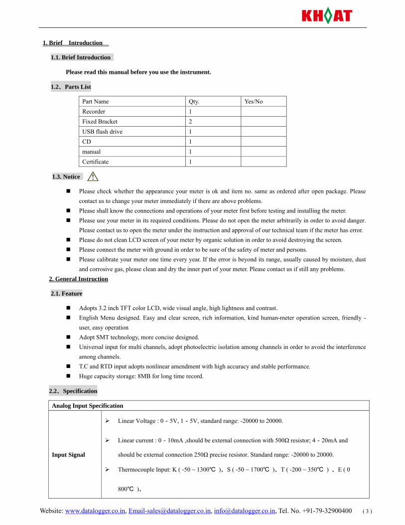
1.2、Parts List
Part Name Qty. Yes/No Recorder 1 Fixed Bracket 2 USB flash drive 1 CD 1 manual 1 Certificate 1
1.3. Notice
Please check whether the appearance your meter is ok and item no. same as ordered after open package. Please contact us to change your meter immediately if there are above problems.
Please shall know the connections and operations of your meter first before testing and installing the meter. Please use your meter in its required conditions. Please do not open the meter arbitrarily in order to avoid danger.
Please contact us to open the meter under the instruction and approval of our technical team if the meter has error. Please do not clean LCD screen of your meter by organic solution in order to avoid destroying the screen. Please connect the meter with ground in order to be sure of the safety of meter and persons. Please calibrate your meter one time every year. If the error is beyond its range, usually caused by moisture, dust
and corrosive gas, please clean and dry the inner part of your meter. Please contact us if still any problems. 2. General Instruction
2.1. Feature
Adopts 3.2 inch TFT color LCD, wide visual angle, high lightness and contrast. English Menu designed. Easy and clear screen, rich information, kind human-meter operation screen, friendly -
user, easy operation Adopt SMT technology, more concise designed. Universal input for multi channels, adopt photoelectric isolation among channels in order to avoid the interference
among channels. T.C and RTD input adopts nonlinear amendment with high accuracy and stable performance. Huge capacity storage: 8MB for long time record.
2.2、Specification
Analog Input Specification
Input Signal
Linear Voltage : 0-5V, 1-5V, standard range: -20000 to 20000.
Linear current : 0-10mA ,should be external connection with 500Ω resistor; 4-20mA and
should be external connection 250Ω precise resistor. Standard range: -20000 to 20000.
Thermocouple Input: K ( -50 ~ 1300 )、S ( -50 ~ 1700 )、T ( -200 ~ 350 ) 、E ( 0
800 )、
Website: www.datalogger.co.in, [email protected], [email protected], Tel. No. +91-79-32900400 ( 4 )
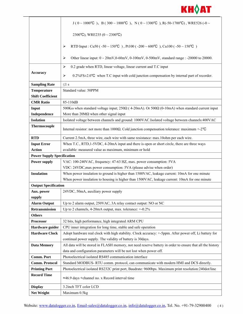
J ( 0 ~ 1000 )、B ( 300 ~ 1800 )、N ( 0 ~ 1300 ), R(-50-1700) , WRE526 (-0 ~
2300), WRE235 (0 ~ 2300)
RTD Input : Cu50 ( -50 ~ 150 ) , Pt100 ( -200 ~ 600 ), Cu100 ( -50 ~ 150 )
Other linear input: 0-20mV,0-60mV, 0-100mV, 0-500mV, standard range : -20000 to 20000.
Accuracy 0.2 grade when RTD, linear voltage, linear current and T.C input
0.2%FS±2.0 when T.C input with cold junction compensation by internal part of recorder.
Sampling Rate ≤1 s Temperature Shift Coefficient
Standard value: 50PPM
CMR Ratio 85-110dB Input Independence
500Kω when standard voltage input; 250Ω ( 4-20mA). Or 500Ω (0-10mA) when standard current input More than 20MΩ when other signal input
Isolation Isolated voltage between channels and ground: 1000VAC.Isolated voltage between channels:400VAC Thermocouple
Internal resistor: not more than 1000Ω. Cold junction compensation tolerance: maximum +-2
RTD Current 2.5mA, three wire, each wire with same resistance: max.10ohm per each wire. Input Error Action
When T.C., RTD,1-5VDC, 4-20mA input and there is open or short circle, there are three ways available: measured value as maximum, minimum or hold
Power Supply Specification Power supply VAC: 100-240VAC, frequency: 47-63 HZ, max. power consumption: 5VA
VDC: 24VDC,max power consumption: 5VA (please advise when order) Insulation When power insulation to ground is higher than 1500VAC, leakage current: 10mA for one minute
When power insulation to housing is higher than 1500VAC, leakage current: 10mA for one minute Output Specification Aux. power supply
24VDC, 50mA, auxiliary power supply
Alarm Output Up to 2 alarm output, 250VAC, 3A relay contact output: NO or NC Retransmission Up to 2 channels, 4-20mA output, max. tolerance: +-0.2% Others Processor 32 bits, high performance, high integrated ARM CPU Hardware guider CPU inner integration for long time, stable and safe operation Hardware Clock Adopt hardware real clock with high stability. Clock accuracy: +-5ppm. After power off, Li battery for
continual power supply. The validity of battery is 30days. Data Memory All data will be stored in FLASH memory, not need reserve battery in order to ensure that all the history
data and configuration parameters will be not lost when power off. Comm. Port Photoelectrical isolated RS485 communication interface Comm. Protocol Standard MODBUS- RTU comm. protocol, can communicate with modern HMI and DCS directly. Printing Port Photoelectrical isolated RS232C print port, Baudrate: 9600bps. Maximum print resolution:240dot/line Record Time
≈46.9 days ÷channel no. x Record interval time
Display 3.2inch TFT color LCD Net Weight Maximum 0.5kg
Website: www.datalogger.co.in, [email protected], [email protected], Tel. No. +91-79-32900400 ( 5 )
Size Dimension: 96mm*96mm*70mm , Install Size: 92mm*92mm Panel Thickness
>1.0mm
Ambient Working Temperature:0-50C, relative humidity; 10%-85%( now dew)
Transport and storage: Temperature: -20-60, relative humidity : 5%-95%(no dew)
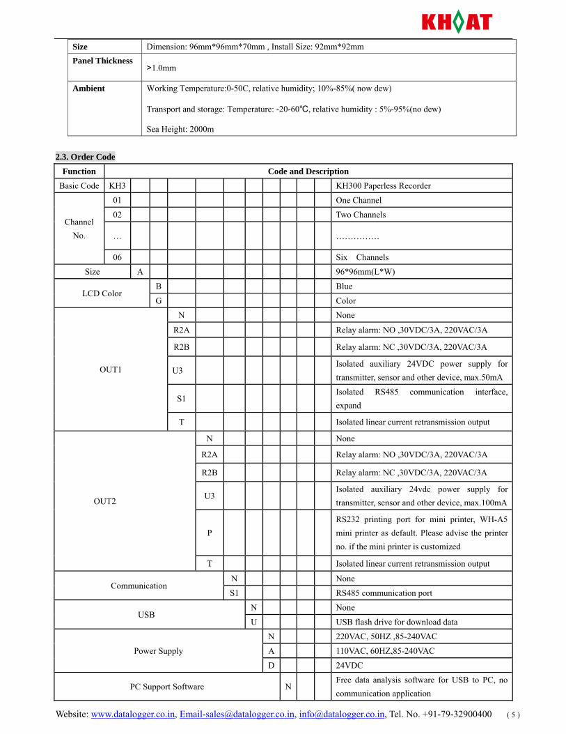
Sea Height: 2000m 2.3. Order Code
Function Code and Description
Basic Code KH3 KH300 Paperless Recorder
Channel No.
01 One Channel
02 Two Channels
… ……………
06 Six Channels
Size A 96*96mm(L*W)
LCD Color B Blue
G Color
OUT1
N None
R2A Relay alarm: NO ,30VDC/3A, 220VAC/3A
R2B Relay alarm: NC ,30VDC/3A, 220VAC/3A
U3 Isolated auxiliary 24VDC power supply for transmitter, sensor and other device, max.50mA
S1 Isolated RS485 communication interface, expand
T Isolated linear current retransmission output
OUT2
N None
R2A Relay alarm: NO ,30VDC/3A, 220VAC/3A
R2B Relay alarm: NC ,30VDC/3A, 220VAC/3A
U3 Isolated auxiliary 24vdc power supply for transmitter, sensor and other device, max.100mA
P RS232 printing port for mini printer, WH-A5 mini printer as default. Please advise the printer no. if the mini printer is customized
T Isolated linear current retransmission output
Communication N None
S1 RS485 communication port
USB N None
U USB flash drive for download data
Power Supply
N 220VAC, 50HZ ,85-240VAC
A 110VAC, 60HZ,85-240VAC
D 24VDC
PC Support Software N Free data analysis software for USB to PC, no communication application
Website: www.datalogger.co.in, [email protected], [email protected], Tel. No. +91-79-32900400 ( 6 )
E Extensive DCS software RS485 communication
Mini Printer
N None
W Yes, Kehao mini dot-matrix printer
Customized mini printer
Metal housing for desktop type
N None
1 Just for recorder
2 both for recorder and mini printer together
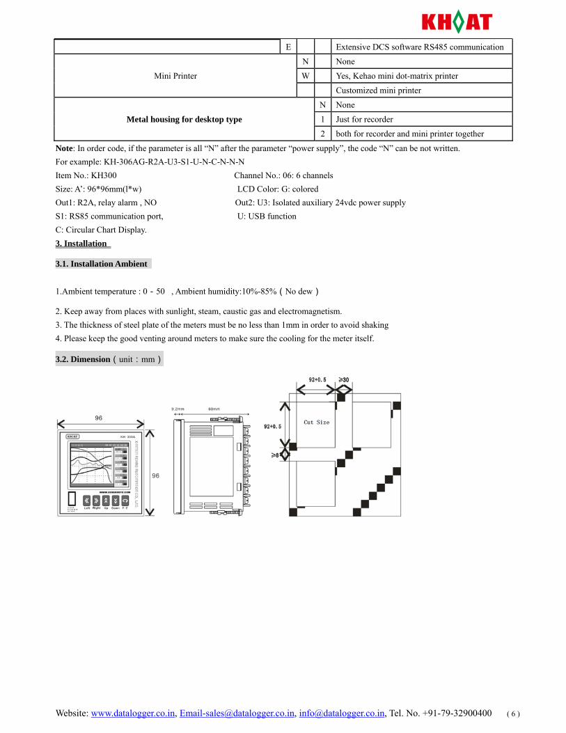
Note: In order code, if the parameter is all “N” after the parameter “power supply”, the code “N” can be not written. For example: KH-306AG-R2A-U3-S1-U-N-C-N-N-N Item No.: KH300 Channel No.: 06: 6 channels Size: A’: 96*96mm(l*w) LCD Color: G: colored Out1: R2A, relay alarm , NO Out2: U3: Isolated auxiliary 24vdc power supply S1: RS85 communication port, U: USB function C: Circular Chart Display. 3. Installation
3.1. Installation Ambient
1.Ambient temperature : 0-50, Ambient humidity:10%-85%(No dew)
2. Keep away from places with sunlight, steam, caustic gas and electromagnetism. 3. The thickness of steel plate of the meters must be no less than 1mm in order to avoid shaking 4. Please keep the good venting around meters to make sure the cooling for the meter itself.
3.2. Dimension(unit:mm)
Website: www.datalogger.co.in, [email protected], [email protected], Tel. No. +91-79-32900400 ( 7 )
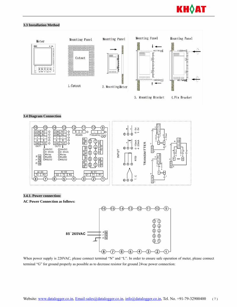
3.3 Installation Method
3.4 Diagram Connection
3.4.1. Power connection: AC Power Connection as follows:
When power supply is 220VAC, please connect terminal “N” and “L”. In order to ensure safe operation of meter, please connect terminal “G” for ground properly as possible as to decrease resistor for ground 24vac power connection:
Website: www.datalogger.co.in, [email protected], [email protected], Tel. No. +91-79-32900400 ( 8 )
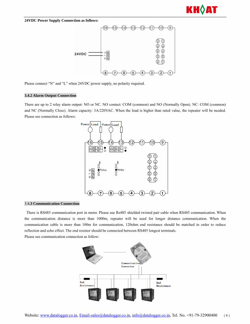
24VDC Power Supply Connection as follows:
Please connect “N” and “L” when 24VDC power supply, no polarity required.
3.4.2 Alarm Output Connection
There are up to 2 relay alarm output: NO or NC. NO contact: COM (common) and NO (Normally Open). NC: COM (common) and NC (Normally Close). Alarm capacity: 3A/220VAC. When the load is higher than rated value, the repeater will be needed. Please see connection as follows:
3.4.3 Communication Connection
There is RS485 communication port in meter. Please use Rs485 shielded twisted pair cable when RS485 communication. When the communication distance is more than 1000m, repeater will be used for longer distance communication. When the communication cable is more than 100m for communication, 120ohm end resistance should be matched in order to reduce reflection and echo effect. The end resistor should be connected between RS485 longest terminals. Please see communication connection as follow:
Website: www.datalogger.co.in, [email protected], [email protected], Tel. No. +91-79-32900400 ( 9 )
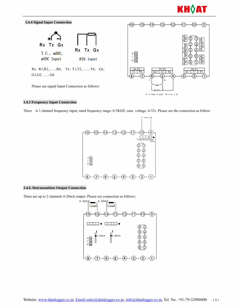
3.4.4 Signal Input Connection
3.4.5 Frequency Input Connection
There is 1 channel frequency input, rated frequency range: 0-5KHZ, max. voltage: 4-32v. Please see the connection as follow:
3.4.6. Retransmition Output Connection
There are up to 2 channels 4-20mA output. Please see connection as follows:
Rx: R1,R2,……R6; Tx: T1,T2,…….T6; Gx: G1,G2…….G6 Please see signal Input Connection as follows:
Website: www.datalogger.co.in, [email protected], [email protected], Tel. No. +91-79-32900400 ( 10 )
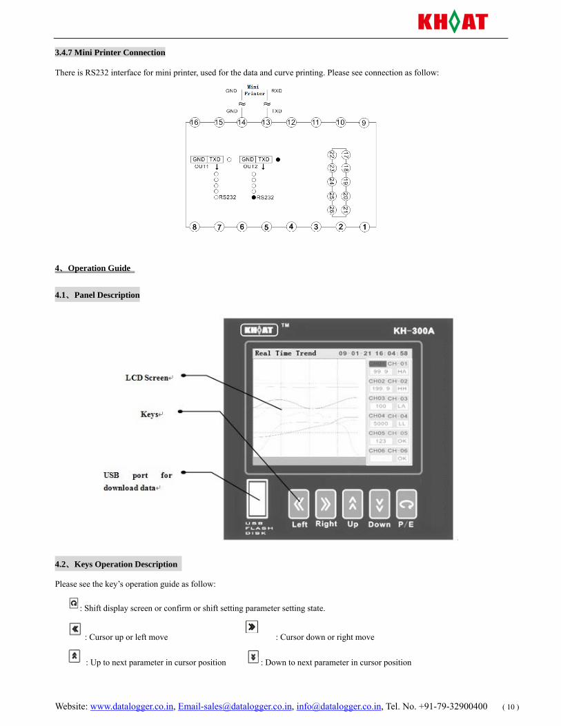
3.4.7 Mini Printer Connection
There is RS232 interface for mini printer, used for the data and curve printing. Please see connection as follow:
4、Operation Guide
4.1、Panel Description
4.2、Keys Operation Description
Please see the key’s operation guide as follow:
: Shift display screen or confirm or shift setting parameter setting state.
: Cursor up or left move : Cursor down or right move
: Up to next parameter in cursor position : Down to next parameter in cursor position
Website: www.datalogger.co.in, [email protected], [email protected], Tel. No. +91-79-32900400 ( 11 )
4.3、Parameter Setting
There are four data types for parameters:Character type, password type, integer number type, fix-point number type
Character type is a fix sequence made of one or more character, such as input type, unit etc. Password type is same as character type, a sequence made of one or more character, but its character has its special meaning, such as password, date, tag no. Integer number type is value with decimal, as baudrate, record interval, filter etc. The fixed point number type is value with fixed or settable decimal point, as range high limit, range low limit, offset etc.
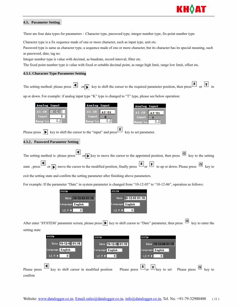
4.3.1. Character Type Parameter Setting
The setting method: please press or key to shift the cursor to the required parameter position, then press or to
up or down. For example: if analog input type “K” type is changed to “T” type, please see below operation:
Please press key to shift the cursor to the “input” and press key to set parameter.
4.3.2、Password Parameter Setting
The setting method is: please press or key to move the cursor to the appointed position, then press key to the setting
state,press or move the cursor to the modified position, finally press or to up or down. Please press key to
exit the setting state and confirm the setting parameter after finishing above parameters.
For example: If the parameter “Date” in system parameter is changed from “10-12-03” to “10-12-06”, operation as follows:
After enter ‘SYSTEM’ parameter screen, please press key to shift cursor to “Date” parameter, then press key to enter the
setting state
Please press key to shift cursor in modified position Please press or key to set Please press key to
confirm
Website: www.datalogger.co.in, [email protected], [email protected], Tel. No. +91-79-32900400 ( 12 )
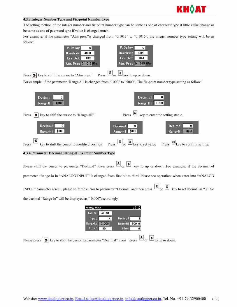
4.3.3 Integer Number Type and Fix-point Number Type The setting method of the integer number and fix point number type can be same as one of character type if little value change or be same as one of password type if value is changed much. For example: if the parameter “Atm pres.”is changed from “0.1013” to “0.1015”, the integer number type setting will be as follow:
Press key to shift the cursor to “Atm pres.” Press or key to up or down
For example: if the parameter “Range-hi” is changed from “1000” to “5000”. The fix-point number type setting as follow:
Press key to shift the cursor to “Range-Hi” Press key to enter the setting statue.
Press key to shift the cursor to modified position Press or key to set value Press key to confirm setting.
4.3.4 Parameter Decimal Setting of Fix Point Number Type
Please shift the cursor to parameter “Decimal” ,then press or key to up or down. For example: if the decimal of
parameter “Range-lo in “ANALOG INPUT” is changed from first bit to third. Please see operation: when enter into “ANALOG
INPUT” parameter screen, please shift the cursor to parameter “Decimal’ and then press or key to set decimal as “3”. So
the decimal “Range-lo” will be displayed as “ 0.000”accordingly.
Please press key to shift the cursor to parameter “Decimal” ,then press or to up or down.
Website: www.datalogger.co.in, [email protected], [email protected], Tel. No. +91-79-32900400 ( 13 )
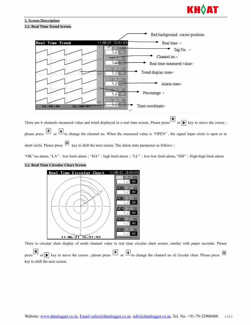
5. Screen Description 5.1. Real Time Trend Screen
There are 6 channels measured value and trend displayed in a real time screen. Please press or key to move the cursor ;
please press or to change the channel no. When the measured value is “OPEN” , the signal input circle is open or in
short circle. Please press key to shift the next screen. The alarm state parameter as follows:
“OK”:no alarm, “LA”:low limit alarm;“HA”:high limit alarm;“LL”:low-low limit alarm, “HH”:High-high limit alarm.
5.2. Real Time Circular Chart Screen
There is circular chart display of multi channel value in real time circular chart screen, similar with paper recorder. Please
press or key to move the cursor ; please press or to change the channel no of circular chart. Please press
key to shift the next screen.
Website: www.datalogger.co.in, [email protected], [email protected], Tel. No. +91-79-32900400 ( 14 )
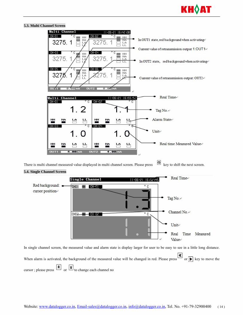
5.3. Multi Channel Screen
There is multi channel measured value displayed in multi channel screen. Please press key to shift the next screen.
5.4. Single Channel Screen
In single channel screen, the measured value and alarm state is display larger for user to be easy to see in a little long distance.
When alarm is activated, the background of the measured value will be changed in red. Please press or key to move the
cursor ; please press or to change each channel no
Website: www.datalogger.co.in, [email protected], [email protected], Tel. No. +91-79-32900400 ( 15 )
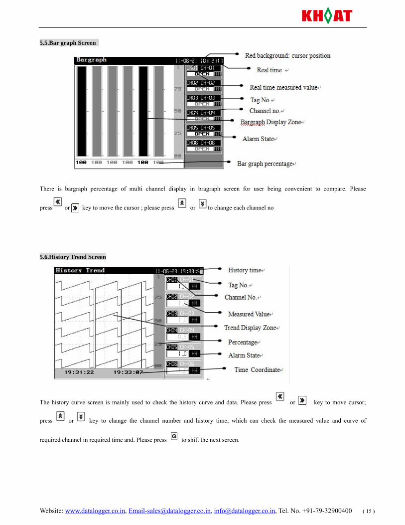
5.5.Bar graph Screen
There is bargraph percentage of multi channel display in bragraph screen for user being convenient to compare. Please
press or key to move the cursor ; please press or to change each channel no
5.6.History Trend Screen
The history curve screen is mainly used to check the history curve and data. Please press or key to move cursor;
press or key to change the channel number and history time, which can check the measured value and curve of
required channel in required time and. Please press to shift the next screen.
Website: www.datalogger.co.in, [email protected], [email protected], Tel. No. +91-79-32900400 ( 16 )
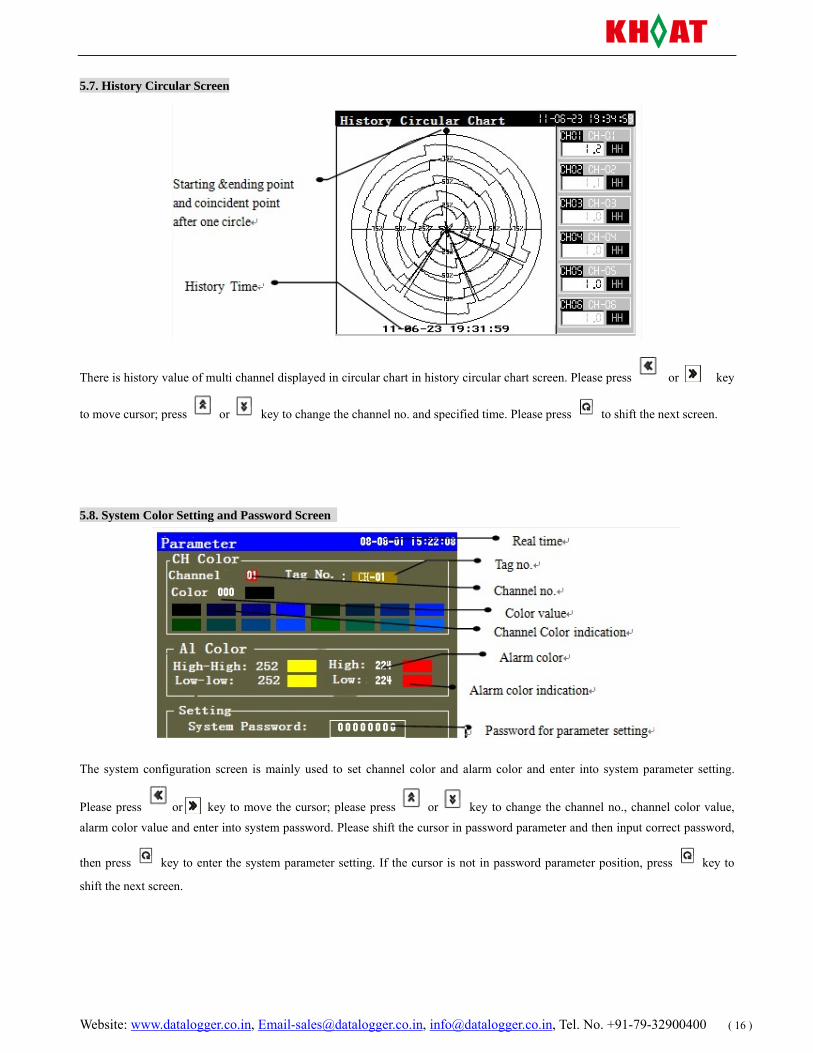
5.7. History Circular Screen
There is history value of multi channel displayed in circular chart in history circular chart screen. Please press or key
to move cursor; press or key to change the channel no. and specified time. Please press to shift the next screen.
5.8. System Color Setting and Password Screen
The system configuration screen is mainly used to set channel color and alarm color and enter into system parameter setting.
Please press or key to move the cursor; please press or key to change the channel no., channel color value, alarm color value and enter into system password. Please shift the cursor in password parameter and then input correct password,
then press key to enter the system parameter setting. If the cursor is not in password parameter position, press key to
shift the next screen.
Website: www.datalogger.co.in, [email protected], [email protected], Tel. No. +91-79-32900400 ( 17 )
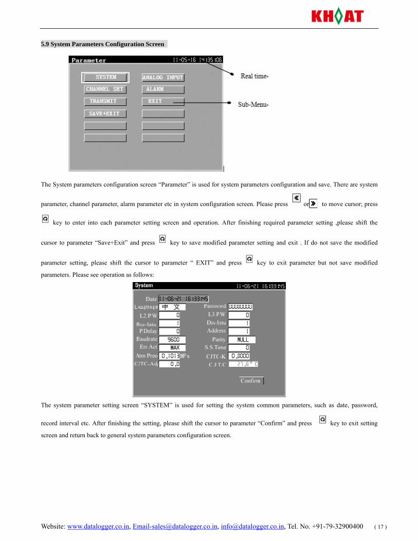
5.9 System Parameters Configuration Screen
The System parameters configuration screen “Parameter” is used for system parameters configuration and save. There are system
parameter, channel parameter, alarm parameter etc in system configuration screen. Please press or to move cursor; press
key to enter into each parameter setting screen and operation. After finishing required parameter setting ,please shift the
cursor to parameter “Save+Exit” and press key to save modified parameter setting and exit . If do not save the modified
parameter setting, please shift the cursor to parameter “ EXIT” and press key to exit parameter but not save modified
parameters. Please see operation as follows:
The system parameter setting screen “SYSTEM” is used for setting the system common parameters, such as date, password,
record interval etc. After finishing the setting, please shift the cursor to parameter “Confirm” and press key to exit setting
screen and return back to general system parameters configuration screen.
Website: www.datalogger.co.in, [email protected], [email protected], Tel. No. +91-79-32900400 ( 18 )
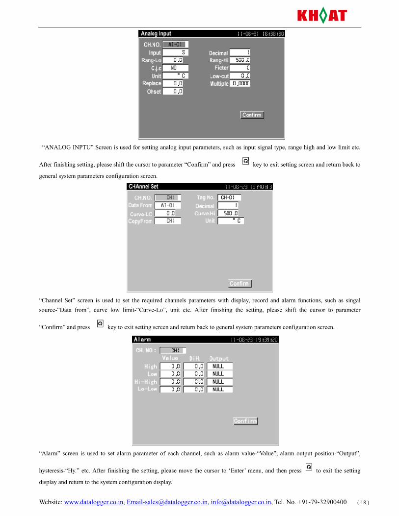
“ANALOG INPTU” Screen is used for setting analog input parameters, such as input signal type, range high and low limit etc.
After finishing setting, please shift the cursor to parameter “Confirm” and press key to exit setting screen and return back to
general system parameters configuration screen.
“Channel Set” screen is used to set the required channels parameters with display, record and alarm functions, such as singal source-“Data from”, curve low limit-“Curve-Lo”, unit etc. After finishing the setting, please shift the cursor to parameter
“Confirm” and press key to exit setting screen and return back to general system parameters configuration screen.
“Alarm” screen is used to set alarm parameter of each channel, such as alarm value-“Value”, alarm output position-“Output”,
hysteresis-“Hy.” etc. After finishing the setting, please move the cursor to ‘Enter’ menu, and then press to exit the setting
display and return to the system configuration display.
Website: www.datalogger.co.in, [email protected], [email protected], Tel. No. +91-79-32900400 ( 19 )
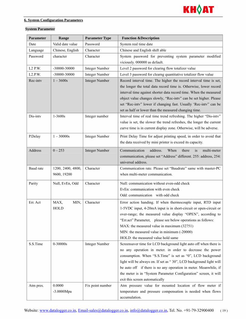
6. System Configuration Parameters
System Parameter
Parameter Range Parameter Type Function &Description Date Valid date value Password System real time date Language Chinese, English Character Chinese and English shift able Password character Character System password for preventing system parameter modified
viciously. 000000 as default. L2 P.W. -30000-30000 Integer Number Level 2 password for clearing flow totalizer value L2.P.W. -30000-30000 Integer Number Level 3 password for clearng quantitative totalizer flow value Rec-intv
1 – 3600s Integer Number Record interval time. The higher the record interval time is set, the longer the total data record time is. Otherwise, lower record interval time against shorter data record time. When the measured object value changes slowly, “Rec-intv” can be set higher. Please set “Rec-intv” lower if changing fast. Usually ‘Rec-intv” can be set as half or lower than the measured changing time.
Dis-intv 1-3600s Integer number Interval time of real time trend refreshing. The higher “Dis-intv” value is set, the slower the trend refreshes, the longer the current curve time is in current display zone. Otherwise, will be adverse.
P.Delay 1 – 30000s Integer Number Print Delay Time for adjust printing speed, in order to avoid that the data received by mini printer is exceed its capacity.
Address 0 – 253 Integer Number Communication address. When there is multi-meter communication, please set “Address” different. 255: address, 254: universal address.
Baud rate 1200, 2400, 4800, 9600, 19200
Character Communication rate. Please set “Baudrate” same with master-PC when multi-meter communication.
Parity Null, EvEn, Odd Character Null: communication without even-odd check EvEn: communication with even check Odd: communication with odd check
Err. Act MAX, MIN, HOLD
Character Error action handing. If when thermocouple input, RTD input 1-5VDC input, 4-20mA input is in short-circuit or open-circuit or over-range; the measured value display “OPEN”, according to “Err.act” Parameter, please see below operations as follows: MAX: the measured value in maximum (32751) MIN: the measured value in minimum (-20000) HOLD: the measured value hold same
S.S.Time 0-30000s Integer Number Screensaver time for LCD background light auto off when there is no any operation in meter. in order to decrease the power consumption. When “S.S.Time” is set as “0”, LCD background light will be always on. If set as “ 30”, LCD background light will be auto off if there is no any operation in meter. Meanwhile, if the meter is in “System Parameter Configuration” screen, it will exit this screen automatically
Atm pres. 0.0000 -3.0000Mpa
Fix point number Atm pressure value for mounted location of flow meter if temperature and pressure compensation is needed when flows accumulation.
Website: www.datalogger.co.in, [email protected], [email protected], Tel. No. +91-79-32900400 ( 20 )
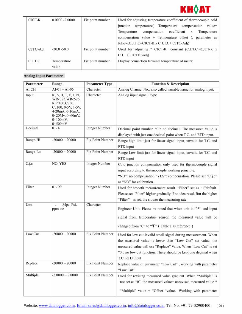
CJCT-K 0.0000 -2.0000 Fix point number Used for adjusting temperature coefficient of thermocouple cold junction temperature( Temperature compensation value= Temperature compensation coefficient x Temperature compensation value + Temperature offset ), parameter as follow:C.J.T.C=CJCT-K x C.J.T.C+ CJTC-Adj)
CJTC-Adj -20.0 -50.0 Fix point number Used for adjusting “ CJCT-K” constant (C.J.T.C.=CJCT-K x C.J.T.C. +CJTC-adj)
C.J.T.C Temperature value
Fix point number Display connection terminal temperature of meter
Analog Input Parameter
Parameter Range Parameter Type Function & Description AI.CH AI-01 ~ AI-06 Character Analog Channel No., also called variable name for analog input.Input K, S, B, T, E, J, N,
WRe325,WRe526,R,Pt100,Cu50, Cu100, 0-5V, 1-5V, 4-20mA, 0-10mA, 0~20Mv, 0~60mV, 0~100mV, 0~500mV
Character Analog input signal l type
Decimal 0 ~ 4 Integer Number Decimal point number. “0”: no decimal. The measured value is displayed with just one decimal point when T.C. and RTD input.
Range-Hi -20000 ~ 20000 Fix Point Number Range high limit just for linear signal input, unvalid for T.C. and RTD input
Range-Lo -20000 ~ 20000 Fix Point Number Range Low limit just for linear signal input, unvalid for T.C. and RTD input
C.j.c NO, YES Integer Number Cold junction compensation only used for thermocouple signal input according to thermocouple working principle. “NO”: no compensation “YES”: compensation. Please set “C.j.c” as “NO” for calibration.
Filter 0 ~ 99 Integer Number Used for smooth measurement result. “Filter” set as “1”default. Please set “Filter” higher gradually if no idea resul. But the higher “Filter” is set, the slower the measuring rate.
Unit 、,Mpa, Psi, ppm etc
CharacterEngineer Unit. Please be noted that when unit is “” and input
signal from temperature sensor, the measured value will be
changed from “C” to “”(Table 1 as reference)
Low Cut -20000 ~ 20000 Fix Point Number Used for low cut invalid small signal during measurement. When the measured value is lower than “Low Cut” set value, the measured value will use “Replace” Value. When “Low Cut” is set “0”, no low cut function. There should be kept one decimal when T.C.,RTD input
Replace -20000 ~ 20000 Fix Point Number Replace value of parameter “Low Cut” , working with parameter “Low Cut”
Multiple -2.0000 ~ 2.0000 Fix Point Number Used for revising measured value gradient. When “Multiple” is not set as “0”, the measured value= unrevised measured value *
“Multiple” value + “Offset “value。Working with parameter
Website: www.datalogger.co.in, [email protected], [email protected], Tel. No. +91-79-32900400 ( 21 )
“Offset” to finish math “y = ax + b”. Offset -10000 ~ 10000 Fix Point Number Used for revising static error of measurement, set “0” as default.
Just when there is a static error, this parameter will be set. Working with parameter “Offset” to finish math “y = ax + b”.
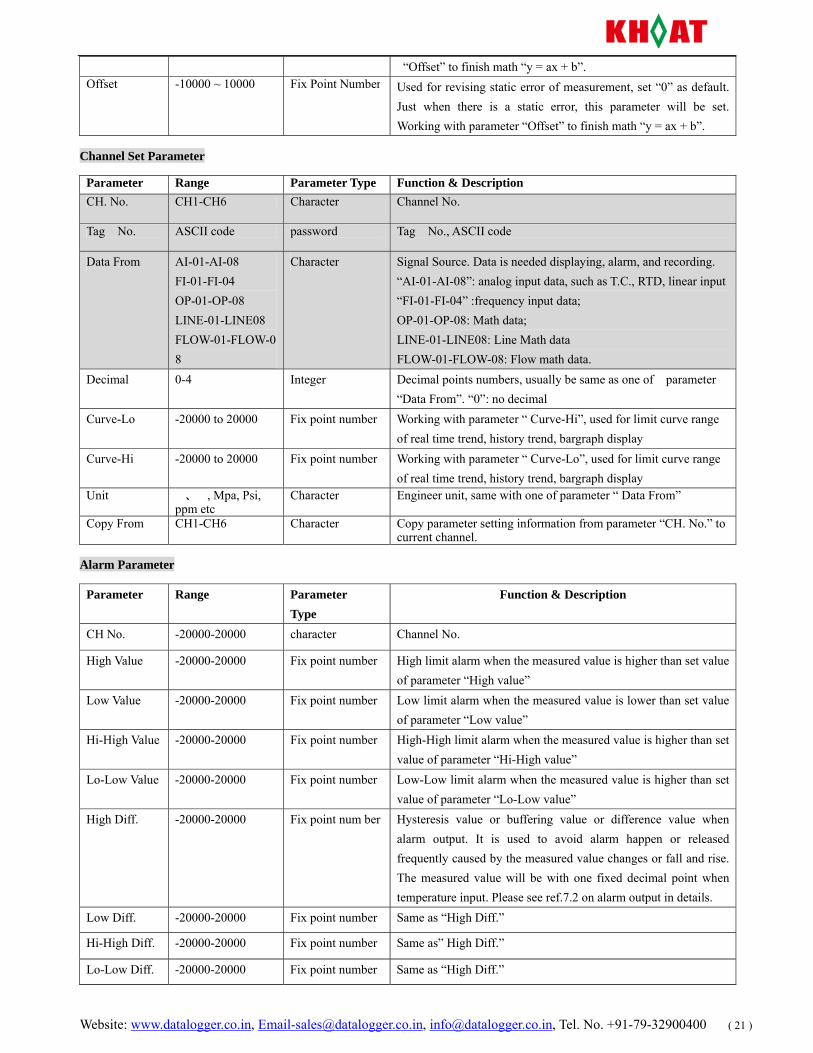
Channel Set Parameter
Parameter Range Parameter Type Function & DescriptionCH. No. CH1-CH6 Character Channel No.
Tag No. ASCII code password Tag No., ASCII code
Data From AI-01-AI-08 FI-01-FI-04 OP-01-OP-08 LINE-01-LINE08 FLOW-01-FLOW-08
Character Signal Source. Data is needed displaying, alarm, and recording. “AI-01-AI-08”: analog input data, such as T.C., RTD, linear input “FI-01-FI-04” :frequency input data; OP-01-OP-08: Math data; LINE-01-LINE08: Line Math data FLOW-01-FLOW-08: Flow math data.
Decimal 0-4 Integer Decimal points numbers, usually be same as one of parameter “Data From”. “0”: no decimal
Curve-Lo -20000 to 20000 Fix point number Working with parameter “ Curve-Hi”, used for limit curve range of real time trend, history trend, bargraph display
Curve-Hi -20000 to 20000 Fix point number Working with parameter “ Curve-Lo”, used for limit curve range of real time trend, history trend, bargraph display
Unit 、, Mpa, Psi, ppm etc
Character Engineer unit, same with one of parameter “ Data From”
Copy From CH1-CH6 Character Copy parameter setting information from parameter “CH. No.” to current channel.
Alarm Parameter
Parameter Range Parameter Type
Function & Description
CH No. -20000-20000 character Channel No.
High Value -20000-20000 Fix point number High limit alarm when the measured value is higher than set value of parameter “High value”
Low Value -20000-20000 Fix point number Low limit alarm when the measured value is lower than set value of parameter “Low value”
Hi-High Value -20000-20000 Fix point number High-High limit alarm when the measured value is higher than set value of parameter “Hi-High value”
Lo-Low Value -20000-20000 Fix point number Low-Low limit alarm when the measured value is higher than set value of parameter “Lo-Low value”
High Diff. -20000-20000 Fix point num ber Hysteresis value or buffering value or difference value when alarm output. It is used to avoid alarm happen or released frequently caused by the measured value changes or fall and rise. The measured value will be with one fixed decimal point when temperature input. Please see ref.7.2 on alarm output in details.
Low Diff. -20000-20000 Fix point number Same as “High Diff.”
Hi-High Diff. -20000-20000 Fix point number Same as” High Diff.”
Lo-Low Diff. -20000-20000 Fix point number Same as “High Diff.”
Website: www.datalogger.co.in, [email protected], [email protected], Tel. No. +91-79-32900400 ( 22 )
High Output NULL,OUT1,OUT2
Character High limit alarm output position for relative channel. “ NULL”: no output
Low Output NULL,OUT1,OUT2
Character Low limit alarm output position for relative channel. “ NULL”: no output
Hi-High Output
NULL,OUT1,OUT2
Character High-High limit alarm output position for relative channel. “ NULL”: no output
Lo-Low Output
NULL,OUT1,OUT2
Character Low-Low limit alarm output position for relative channel. “ NULL”: no output
Transmit Parameter
Parameter Range Parameter Type
Function & Description
Trans.CH Tout-01 ~ Tout-02 Character Channel No. of retransmission
Data From
NULL,AI-01~AI-08, FI-01 ~FI-04, OP-01~ OP-08, LINE-01~LINE-08, FLOW-01~FLOW-08
Character
Signal Source. Data is needed displaying, alarm, and recording. “AI-01-AI-08”: analog input data, such as T.C., RTD, linear input “FI-01-FI-04” :frequency input data; OP-01-OP-08: Math data; LINE-01-LINE08: Line Math data FLOW-01-FLOW-08: Flow math data.
Decimal 0 ~ 4 Integer Number Decimal points numbers, usually be same as one of parameter “Data From”. “0”: no decimal
Trans-Lo -20000 ~ 20000 Fix Point Number
Low limit value of retransmission output range
Trans-Hi -20000 ~ 20000 Fix Point Number
High limit value of retransmission output range
7、Function Description
7.1、Digital Filter
When there is digital change and jump caused by input signal with interference, it can adopt digital filter to make it smooth. The range of “Filter” is 0-99. “ 0” is no any filter. When “Filter “ value is is higher, the measured value is more stable but ther responding rate will be slower. When there is strong interference on the measured value, the value “Filter” can be increased higher gradually to make the measured value changes instantaneously during less than 2-5 digits. Please set “Filter” as 0 to increase the respond speed when calibration in lab.
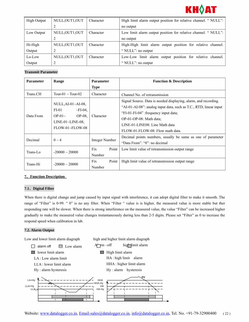
7.2. Alarm Output
Low and lower limit alarm diagraph high and higher limit alarm diagraph Alarm –off high limit alarm
alarm off Low alarm
LA
LA+Hy
LLA LLA+Hy
PV HA
HHA-Hy HHA
HA-Hy
PV
lower limit alarm Upper a alarm stop High limit alarm LA : Low alarm limit LLA : lower limit alarm Hy : alarm hysteresis
HA : high limit alarm HHA : higher limit alarm Hy : alarm hysteresis
Website: www.datalogger.co.in, [email protected], [email protected], Tel. No. +91-79-32900400 ( 23 )
7.3 transmitter output
The transmission function is current signal output according to measured value (PV) and retransmission range. Please see below calculation format of retransmission current output:
Transmission current Value= ----------------------------------------------- + 4mA It is assumed that the retransmission parameter setting as follows: ‘Tran.CH’=”Tout-01”, ‘DataFrom’= “AI-01”, ‘Trans-Lo’=0, ‘Trans-Hi’=1300
So:When PV( measured value)≤0, retransmission output is4 m A.
When PV (measured value)≥1300, retransmission output is 20m A. When PV (measured value) =650, re transmission output is12 m A. 8. Data Analysis Software
8.1、Download Data from Recorder
1. Please be advised that USB flash drive file format is ‘FAT16’ default. If not, please format it to ‘FAT16’. 2. Please ensure USB flash drive with enough space for memory, which should be more than recorder itself storage capacity (8MB default).
3. Please insert USB flash drive into USB interface at the front panel of recorder. So the “DAT” format file will be made automatically in USB flash drive, also named automatically in current year, month and data format, such as 050811.dat. (05: year in 2005, 08: month in August, 27: day in 11th) . During download data, the recorder will display “Save data…” in the top of the screen with USB red light flashing. Please do not take out the USB flash drive during downloading data from recorder so that it affects normal working of the recorder. 4. If there is something wrong during download data from recorder, please take out USB flash drive and confirm above point 1
and point 2 again. If the screen displays error, please press “ ” key to shift the screen, will be ok.
5. when the screen display” Save data….OK” and red light not flashing in USB flash drive, please take out USB flash drive for further analysis to PC. Finish Download.
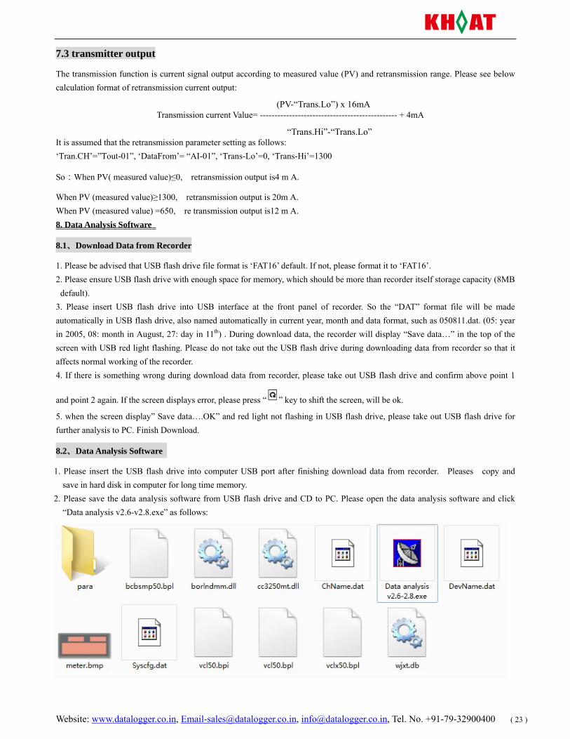
8.2、Data Analysis Software
1. Please insert the USB flash drive into computer USB port after finishing download data from recorder. Pleases copy and save in hard disk in computer for long time memory.
2. Please save the data analysis software from USB flash drive and CD to PC. Please open the data analysis software and click “Data analysis v2.6-v2.8.exe” as follows:
(PV-“Trans.Lo”) x 16mA
“Trans.Hi”-“Trans.Lo”
Website: www.datalogger.co.in, [email protected], [email protected], Tel. No. +91-79-32900400 ( 24 )
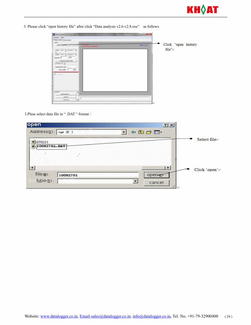
3. Please click “open history file” after click “Data analysis v2.6-v2.8.exe” as follows
3.Plase select data file in “ .DAT “ format:
Website: www.datalogger.co.in, [email protected], [email protected], Tel. No. +91-79-32900400 ( 25 )
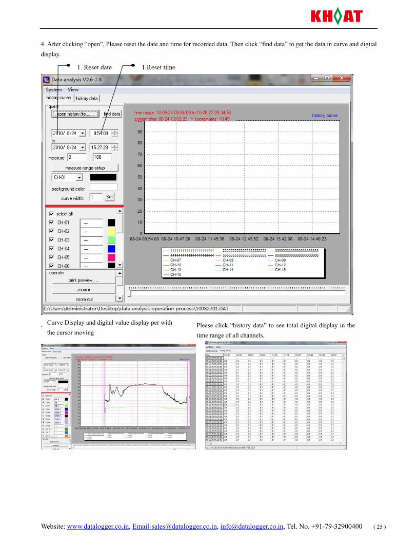
4. After clicking “open”, Please reset the date and time for recorded data. Then click “find data” to get the data in curve and digital display.
.
1. Reset date 1.Reset time
Curve Display and digital value display per with the cursor moving
Please click “history data” to see total digital display in the time range of all channels.
Website: www.datalogger.co.in, [email protected], [email protected], Tel. No. +91-79-32900400 ( 26 )
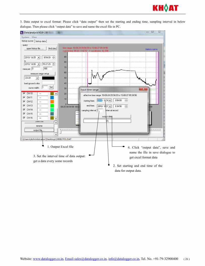
3. Data output to excel format: Please click “data output” then set the starting and ending time, sampling interval in below dialogue. Then please click “output data” to save and name the excel file in PC.
4. Click “output data”, save and name the file in save dialogue to get excel format data
2. Set starting and end time of the data for output data.
3. Set the interval time of data output: get a data every some records
1. Output Excel file
Website: www.datalogger.co.in, [email protected], [email protected], Tel. No. +91-79-32900400 ( 27 )
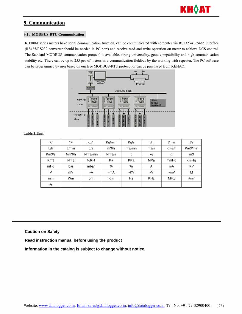
9. Communication
9.1、MODBUS-RTU Communication
KH300A series meters have serial communication function, can be communicated with computer via RS232 or RS485 interface (RS485/RS232 converter should be needed in PC port) and receive read and write operation on meter to achieve DCS control. The Standard MODBUS communication protocol is available, strong universality, good compatibility and high communication stability etc. There can be up to 255 pcs of meters in a communication fieldbus by the working with repeater. The PC software can be programmed by user based on our free MODBUS-RTU protocol or can be purchased from KEHAO.
Table 1:Unit
°C °F Kg/h Kg/min Kg/s t/h t/min t/s
L/h L/min L/s m3/h m3/min m3/s Km3/h Km3/min
Km3/s Nm3/h Nm3/min Nm3/s t kg g m3
Km3 Nm3 %RH Pa KPa MPa mmHg cmHg
mHg bar mbar % ‰ A mA KV
V mV ~A ~mA ~KV ~V ~mV M
mm Wm cm Km Hz KHz MHz r/min
r/s
Caution on Safety
Read instruction manual before using the product
Information in the catalog is subject to change without notice.


