
2
Contents
Introduction ................................................ 4Main Features ............................................ 4How the iWAVESTATION is structured ........... 5
Performances .............................................................................5Patches ........................................................................................5Waveforms ..................................................................................6Wave sequences .........................................................................6Cards ...........................................................................................6
Part Names and Functions ............................ 7Browser functions .................................... 14
Selecting a performance .........................................................14Selecting Wave sequences, Paches, and Waves .....................15Scale list ....................................................................................16
Parameters for each page........................... 17WAVESEQ ................................................. 17
WAVE page ...............................................................................18LEVEL page ...............................................................................18LOOP page ................................................................................18PITCH page ...............................................................................19PARAM page .............................................................................19
MIXER ...................................................... 21MIXER page ..............................................................................22MIDI page .................................................................................23
EDIT ........................................................ 25How a Patch is structured ........................................................25
Oscillators ....................................................................................... 25Vector synthesis ........................................................................... 25Waves ............................................................................................... 26Wave sequences ........................................................................... 26Filter .................................................................................................. 26Pan .................................................................................................... 27Modulation .................................................................................... 27
A brief introduction to wave sequences ................................28MORPH page ............................................................................31
MORPH ............................................................................................ 31MODULATION ............................................................................... 32
WAVE page ...............................................................................33Level ................................................................................................. 33Semi .................................................................................................. 35Fine ................................................................................................... 36Settings ........................................................................................... 36Write ................................................................................................. 38
TONE page ................................................................................38PITCH ................................................................................................ 38FILTER ............................................................................................... 40
3
OUTPUT page ...........................................................................41AMPLIFIER ....................................................................................... 41FX-BUS ............................................................................................. 42A-B PAN............................................................................................ 42
MOD page .................................................................................43ENV .................................................................................................... 43LFO 1/2 ............................................................................................ 44
EFFECTS ................................................... 46Effect system ............................................................................46Effect structure .........................................................................46
EFFECT ROUTING ......................................................................... 47Effect list ...................................................................................50
SETTINGS ................................................. 56MIDI Settings ............................................................................56MIDI Filtering ...........................................................................57Tuning .......................................................................................57Tempo Source ...........................................................................58
Writing, Importing and Exporting Data ....... 59Writing data..............................................................................59
Performances ................................................................................ 59Patches ............................................................................................ 59Wave sequences ........................................................................... 60
Import .......................................................................................60iWAVESTATION .............................................................................. 60KORG Legacy Collection ............................................................ 60Original WAVESTATION SysEx .................................................. 60
Export .......................................................................................60
Specifications ............................................ 61
Support and service ................................... 62Information to provide when contacting us...................... 62Before you contact us ................................................................ 62
4
Introduction
Thank you for purchasing the KORG iWAVESTATION for iOS Wave sequence synthesizer. To help you get the most out of your new instrument, please read this manual carefully.
Main FeaturesThe iWAVESTATION features a new graphical user inter-face that brings a revolutionary leap in user operations. It also provides all waves, effects, and sound programs found on the original WAVESTATION series, delivering a perfect reproduction of the original sound.All 550 of the factory preset programs (performances) from the WAVESTATION series are provided as presets. Perfor-mances, patches, and wave sequence data created on the original WAVESTATION series can also be loaded as system exclusive files. Also. seven types of cards (CARD 1–6, KLC 1) have been added as contents that can be purchased. These cards allow the performances, patches, wave sequences and waves of the iWAVESTATION to be expanded.
5
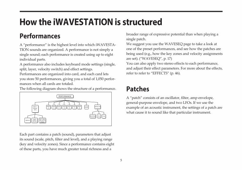
How the iWAVESTATION is structuredPerformancesA “performance” is the highest level into which iWAVESTA-TION sounds are organized. A performance is not simply a single sound; each performance is created using up to eight individual parts.A performance also includes keyboard mode settings (single, split, layer, velocity switch) and effect settings.Performances are organized into card, and each card lets you store 50 performances, giving you a total of 1,050 perfor-mances when all cards are totaled.The following diagram shows the structure of a performance.
Each part contains a patch (sound), parameters that adjust its sound (scale, pitch, filter and level), and a playing range (key and velocity zones). Since a performance contains eight of these parts, you have much greater tonal richness and a
broader range of expressive potential than when playing a single patch. We suggest you use the WAVESEQ page to take a look at one of the preset performances, and see how the patches are being used (e.g., how the key zones and velocity assignments are set). (“WAVESEQ”, p. 17)You can also apply two stereo effects to each performance, and adjust their effect parameters. For more about the effects, refer to refer to “EFFECTS” (p. 46).
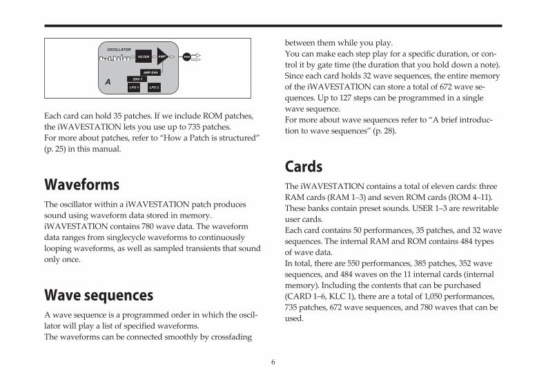
PatchesA “patch” consists of an oscillator, filter, amp envelope, general-purpose envelope, and two LFOs. If we use the example of an acoustic instrument, the settings of a patch are what cause it to sound like that particular instrument.
PERFORMANCE
PART 1(typical
of 8)
PATCHPART
DETAILKEY AND VELOCTY
ZONES
PART2
PART3
PART4
PART5
PART6
PART7
PART8
NAME EFFECTS
ROUTING FX1 FX2
6
Each card can hold 35 patches. If we include ROM patches, the iWAVESTATION lets you use up to 735 patches.For more about patches, refer to “How a Patch is structured” (p. 25) in this manual.
WaveformsThe oscillator within a iWAVESTATION patch produces sound using waveform data stored in memory.iWAVESTATION contains 780 wave data. The waveform data ranges from singlecycle waveforms to continuously looping waveforms, as well as sampled transients that sound only once.
Wave sequencesA wave sequence is a programmed order in which the oscil-lator will play a list of specified waveforms.The waveforms can be connected smoothly by crossfading
between them while you play.You can make each step play for a specific duration, or con-trol it by gate time (the duration that you hold down a note).Since each card holds 32 wave sequences, the entire memory of the iWAVESTATION can store a total of 672 wave se-quences. Up to 127 steps can be programmed in a single wave sequence.For more about wave sequences refer to “A brief introduc-tion to wave sequences” (p. 28).
CardsThe iWAVESTATION contains a total of eleven cards: three RAM cards (RAM 1–3) and seven ROM cards (ROM 4–11). These banks contain preset sounds. USER 1–3 are rewritable user cards.Each card contains 50 performances, 35 patches, and 32 wave sequences. The internal RAM and ROM contains 484 types of wave data.In total, there are 550 performances, 385 patches, 352 wave sequences, and 484 waves on the 11 internal cards (internal memory). Including the contents that can be purchased (CARD 1–6, KLC 1), there are a total of 1,050 performances, 735 patches, 672 wave sequences, and 780 waves that can be used.
PAN
OSCILLATOR
FILTER AMP
AMP ENV
ENV 1
LFO 1 LFO 2A
7
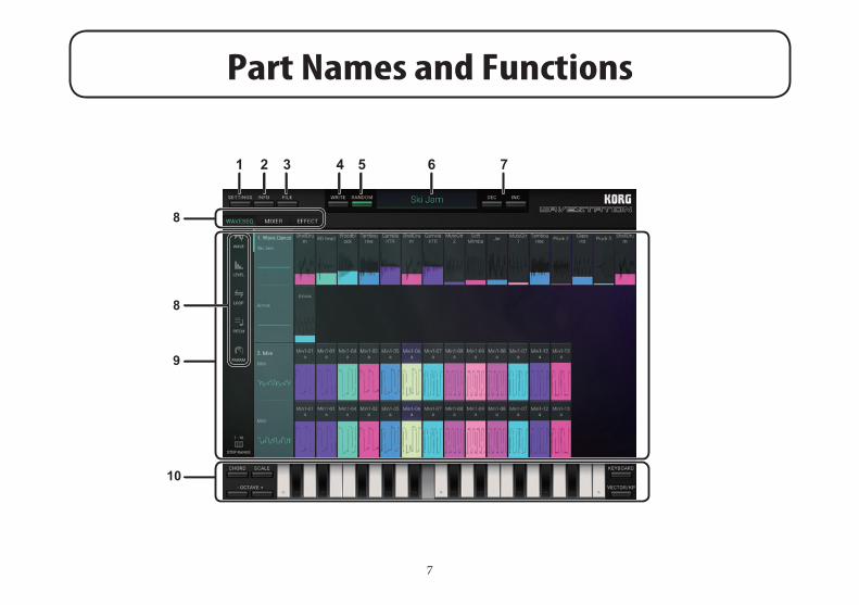
Part Names and Functions
1 2 3 5 6
8
9
10
8
4 7
8
1. SETTINGS buttonThis includes global settings for the iWAVESTATION, in-cluding Master Tune, Transpose, MIDI Filter, User Scale and so on (“SETTINGS”, p. 56).Tap the SETTINGS button and select the desired command from the menu.
2. INFO buttonPressing the INFO button will display the version number ofthe iWAVESTATION, plus additional instructions on how to use it.Manual: Displays this Owner’s Manual.FAQ: Displays the KORG App Help Center.
note You’ll need an Internet connection in order to view the operating manual or the KORG App Help Center.
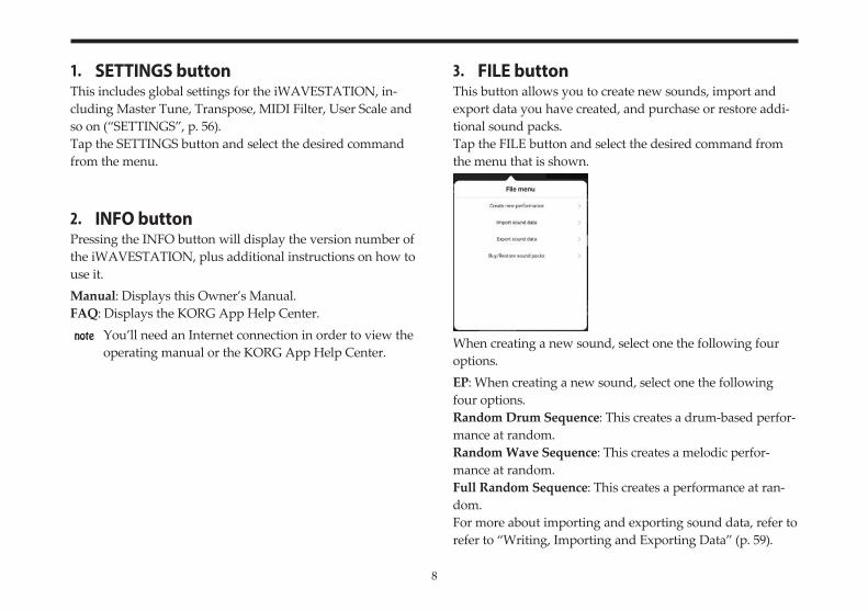
3. FILE buttonThis button allows you to create new sounds, import and export data you have created, and purchase or restore addi-tional sound packs.Tap the FILE button and select the desired command from the menu that is shown.
When creating a new sound, select one the following four options.EP: When creating a new sound, select one the following four options.Random Drum Sequence: This creates a drum-based perfor-mance at random.Random Wave Sequence: This creates a melodic perfor-mance at random.Full Random Sequence: This creates a performance at ran-dom.For more about importing and exporting sound data, refer to refer to “Writing, Importing and Exporting Data” (p. 59).
9
4. WRITE buttonSelects where you want to write the performance to refer to “Performances” (p. 59).
5. RANDOM buttonThis creates a random performance each time the button is pressed. This is the same as the “Full Random Sequence”, accessed using the FILE button.
6. Performance NameThis area of the screen displays the name of the currently selected Performance.To switch to a different Performance, simply tap the name (Refer to refer to “Browser functions” (p. 14)).
7. DEC/INC buttonsThis calls up the performance before or after the one that is currently selected.
8. Page select switchesThese buttons are used to select the WAVESEQ, MIXER, EF-FECT and related edit pages.The parameters for the selected pages are shown in the edit area.WAVESEQ: Selects WAVESEQ (p. 17).• WAVE page (p. 18)• LEVEL page (p. 18)• LOOP page (p. 18)• PITCH page (p. 19)• PARAM page (p. 19)
MIXER: Selects MIXER (p. 21).• MIXER page (p. 22)• MIDI page (p. 23)
EFFECT: Selects EFFECT (p. 46).EDIT: Selects EDIT (p. 25).• MORPH page (p. 31)• WAVE page (p. 33)• TONE page (p. 38)• OUTPUT page (p. 41)• MOD page (p. 43)
10
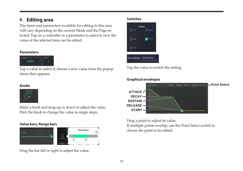
9. Editing areaThe items and parameters available for editing in this area will vary depending on the current Mode and the Page se-lected. Tap on a controller or a parameter to select it; now the value of the selected item can be edited.
Parameters
Tap a value to select it; choose a new value from the popup menu that appears.
Knobs
Select a knob and drag up or down to adjust the value.Flick the knob to change the value in single steps.
Value bars, Range bars
Drag the bar left or right to adjust the value.
Switches
Tap the value to switch the setting.
Graphical envelopes
Drag a point to adjust its value.If multiple points overlap, use the Point Select switch to choose the point to be edited.
DECAYATTACK
RELEASESUSTAIN
START
Point Select
11
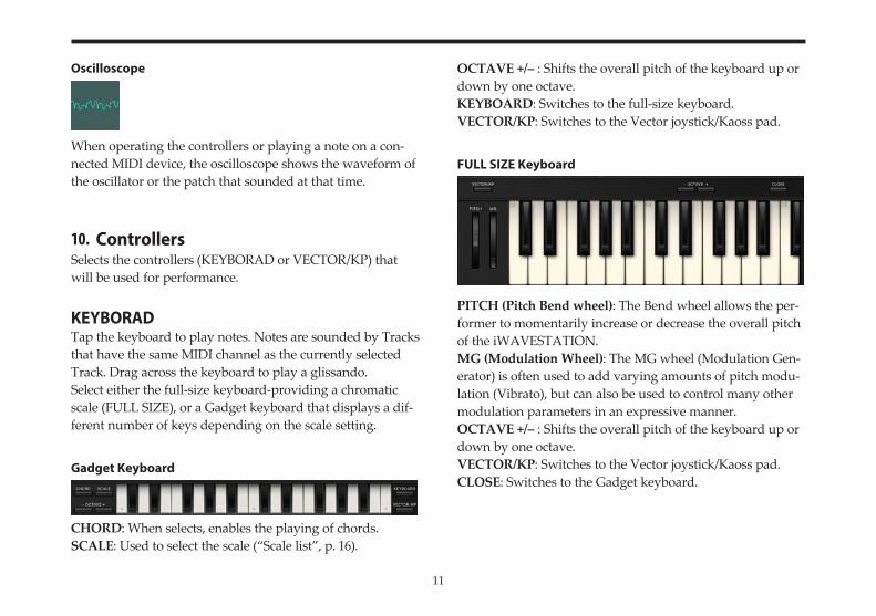
Oscilloscope
When operating the controllers or playing a note on a con-nected MIDI device, the oscilloscope shows the waveform of the oscillator or the patch that sounded at that time.
10. ControllersSelects the controllers (KEYBORAD or VECTOR/KP) that will be used for performance.
KEYBORADTap the keyboard to play notes. Notes are sounded by Tracks that have the same MIDI channel as the currently selected Track. Drag across the keyboard to play a glissando.Select either the full-size keyboard-providing a chromatic scale (FULL SIZE), or a Gadget keyboard that displays a dif-ferent number of keys depending on the scale setting.
Gadget Keyboard
CHORD: When selects, enables the playing of chords.SCALE: Used to select the scale (“Scale list”, p. 16).
OCTAVE +/– : Shifts the overall pitch of the keyboard up or down by one octave.KEYBOARD: Switches to the full-size keyboard.VECTOR/KP: Switches to the Vector joystick/Kaoss pad.
FULL SIZE Keyboard
PITCH (Pitch Bend wheel): The Bend wheel allows the per-former to momentarily increase or decrease the overall pitch of the iWAVESTATION.MG (Modulation Wheel): The MG wheel (Modulation Gen-erator) is often used to add varying amounts of pitch modu-lation (Vibrato), but can also be used to control many other modulation parameters in an expressive manner.OCTAVE +/– : Shifts the overall pitch of the keyboard up or down by one octave.VECTOR/KP: Switches to the Vector joystick/Kaoss pad.CLOSE: Switches to the Gadget keyboard.

12
VECTOR/KP (Vector joystick/Kaoss pad)
KEYBOARD: Switches to the full-size keyboard.CLOSE: Switches to the gadget keyboard.
Vector joystickOperating the vector joystick will control the parameters that are assigned to the A–C axes and the B–D axes.MIDI control changes can be used on external MIDI devices that are connected to change the joystick values of the joy-stick as well.
AXIS A–C/AXIS B–DThis sets the parameters that are assigned to the A–C axes and the B–D axes of the vector joystick.NONE: Nothing will happen when the vector joystick is operated.
MIX ENV X, MIX ENV Y: Controls the mix balance of the wave sequences.ATTACK: Controls both the AMPLIFIER envelope start level and attack time (“Envelope (graphical envelope)”, p. 41).RELEASE: Controls both the decay and release times of the envelope on the AMPLIFIER.CUTOFF: Controls the “Cutoff” (p. 40) parameter on the FILTER.RESONANCE/EXCITER: Controls the “Mode” (p. 40) of the FILTER.OSC A LFO1 RATE: Controls the “Amount” (p. 45) of the LFO 1 RATE MODULATION.OSC A LFO1 DEPTH: Controls the “Amount” (p. 44) of the LFO 1 DEPTH MODULATION.
AXIS A-C/AXIS B-D
CLOSEKEYBOARD SCALE
VOICE
Vector joystick Kaoss pad
13
Kaoss padControls the parameters that are set when dragging across a pad for the X-axis (horizontal direction) and Y-axis (vertical direction).For the X-axis direction, the pitch changes according to the key and scale set in “SCALE”.For the Y-axis direction, the inversion when playing a chord can be controlled. This has no effect when set to “MONO”.SCALE: Selects the scale to be performed when playing on the pad (“Scale list”, p. 16).VOICE: This sets the number of notes that will sound when operating the pad. When sounding a chord with a setting other than MONO, the inversion can be controlled for the chord using the Y-axis.
14
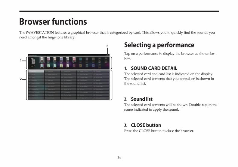
Browser functionsThe iWAVESTATION features a graphical browser that is categorized by card. This allows you to quickly find the sounds you need amongst the huge tone library.
Selecting a performanceTap on a performance to display the browser as shown be-low.
1. SOUND CARD DETAILThe selected card and card list is indicated on the display. The selected card contents that you tapped on is shown in the sound list.
2. Sound listThe selected card contents will be shown. Double-tap on the name indicated to apply the sound.
3. CLOSE buttonPress the CLOSE button to close the browser.
3
1
2
15
Selecting Wave sequences, Pach-es, and WavesThe versatile iWAVESTATION Browser can also be used to find wave sequences, patches, and waves. Tap the name shown in the edit area of the WAVE page, LEVEL page etc., and the Browser will appear.
16
Scale list
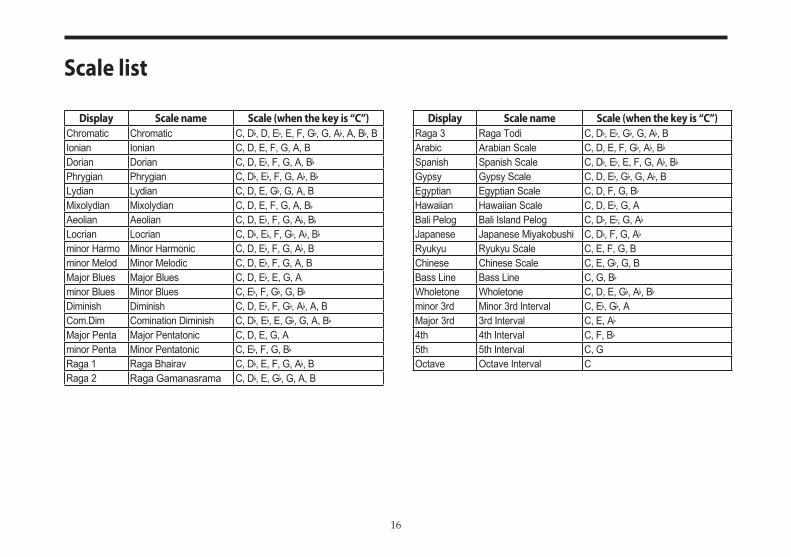
Display Scale name Scale (when the key is “C”)Chromatic Chromatic C, D♭, D, E♭, E, F, G♭, G, A♭, A, B♭, BIonian Ionian C, D, E, F, G, A, BDorian Dorian C, D, E♭, F, G, A, B♭Phrygian Phrygian C, D♭, E♭, F, G, A♭, B♭Lydian Lydian C, D, E, G♭, G, A, BMixolydian Mixolydian C, D, E, F, G, A, B♭Aeolian Aeolian C, D, E♭, F, G, A♭, B♭Locrian Locrian C, D♭, E♭, F, G♭, A♭, B♭minor Harmo Minor Harmonic C, D, E♭, F, G, A♭, Bminor Melod Minor Melodic C, D, E♭, F, G, A, BMajor Blues Major Blues C, D, E♭, E, G, Aminor Blues Minor Blues C, E♭, F, G♭, G, B♭Diminish Diminish C, D, E♭, F, G♭, A♭, A, BCom.Dim Comination Diminish C, D♭, E♭, E, G♭, G, A, B♭Major Penta Major Pentatonic C, D, E, G, Aminor Penta Minor Pentatonic C, E♭, F, G, B♭Raga 1 Raga Bhairav C, D♭, E, F, G, A♭, BRaga 2 Raga Gamanasrama C, D♭, E, G♭, G, A, B
Display Scale name Scale (when the key is “C”)Raga 3 Raga Todi C, D♭, E♭, G♭, G, A♭, BArabic Arabian Scale C, D, E, F, G♭, A♭, B♭Spanish Spanish Scale C, D♭, E♭, E, F, G, A♭, B♭Gypsy Gypsy Scale C, D, E♭, G♭, G, A♭, BEgyptian Egyptian Scale C, D, F, G, B♭Hawaiian Hawaiian Scale C, D, E♭, G, ABali Pelog Bali Island Pelog C, D♭, E♭, G, A♭Japanese Japanese Miyakobushi C, D♭, F, G, A♭Ryukyu Ryukyu Scale C, E, F, G, BChinese Chinese Scale C, E, G♭, G, BBass Line Bass Line C, G, B♭Wholetone Wholetone C, D, E, G♭, A♭, B♭minor 3rd Minor 3rd Interval C, E♭, G♭, AMajor 3rd 3rd Interval C, E, A♭4th 4th Interval C, F, B♭5th 5th Interval C, GOctave Octave Interval C
17
Parameters for each page
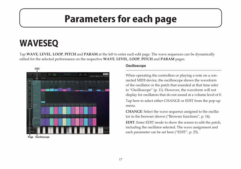
WAVESEQTap WAVE, LEVEL, LOOP, PITCH and PARAM at the left to enter each edit page. The wave sequences can be dynamically edited for the selected performance on the respective WAVE, LEVEL, LOOP, PITCH and PARAM pages.
Oscilloscope......................................................................................................................
When operating the controllers or playing a note on a con-nected MIDI device, the oscilloscope shows the waveform of the oscillator or the patch that sounded at that time refer to “Oscilloscope” (p. 11). However, the waveform will not display for oscillators that do not sound at a volume level of 0.Tap here to select either CHANGE or EDIT from the pop-up menu.CHANGE: Select the wave sequence assigned to the oscilla-tor in the browser shown (“Browser functions”, p. 14).EDIT: Enter EDIT mode to show the screen to edit the patch, including the oscillator selected. The wave assignment and each parameter can be set here (“EDIT”, p. 25).
OSC
OscilloscopePage
18
STEP RANGE......................................................................................................................Shows the range for the currently displayed step.Tap this range and move the range bar of the pop-up menu shown to change the range of the steps that are displayed (“Value bars, Range bars”, p. 10). If the selected perfor-mance is 16 steps or less, the range bar cannot be moved.
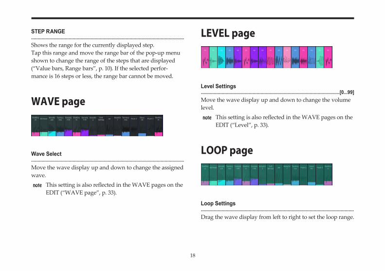
WAVE page
Wave Select......................................................................................................................Move the wave display up and down to change the assigned wave.
note This setting is also reflected in the WAVE pages on the EDIT (“WAVE page”, p. 33).
LEVEL page
Level Settings...........................................................................................................[0...99]Move the wave display up and down to change the volume level.
note This setting is also reflected in the WAVE pages on the EDIT (“Level”, p. 33).
LOOP page
Loop Settings......................................................................................................................Drag the wave display from left to right to set the loop range.
19
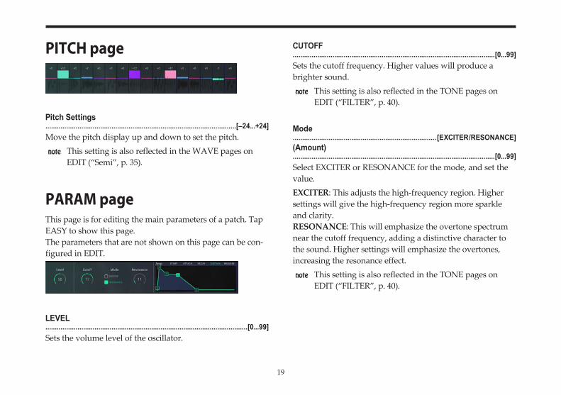
PITCH page
Pitch Settings.....................................................................................................[–24...+24]Move the pitch display up and down to set the pitch.
note This setting is also reflected in the WAVE pages on EDIT (“Semi”, p. 35).
PARAM pageThis page is for editing the main parameters of a patch. Tap EASY to show this page.The parameters that are not shown on this page can be con-figured in EDIT.
LEVEL...........................................................................................................[0...99]Sets the volume level of the oscillator.
CUTOFF...........................................................................................................[0...99]Sets the cutoff frequency. Higher values will produce a brighter sound.
note This setting is also reflected in the TONE pages on EDIT (“FILTER”, p. 40).
Mode............................................................................ [EXCITER/RESONANCE](Amount)...........................................................................................................[0...99]Select EXCITER or RESONANCE for the mode, and set the value.EXCITER: This adjusts the high-frequency region. Higher settings will give the high-frequency region more sparkle and clarity.RESONANCE: This will emphasize the overtone spectrum near the cutoff frequency, adding a distinctive character to the sound. Higher settings will emphasize the overtones, increasing the resonance effect.
note This setting is also reflected in the TONE pages on EDIT (“FILTER”, p. 40).
20
AMP (AMP EG)......................................................................................................................Controls the volume over time.Drag each point on the graphical envelope (“Graphical enve-lopes”, p. 10).
note This setting is also reflected in the OUTPUT pages on EDIT (“Envelope (graphical envelope)”, p. 41).
21
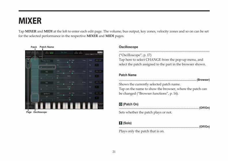
MIXERTap MIXER and MIDI at the left to enter each edit page. The volume, bus output, key zones, velocity zones and so on can be set for the selected performance in the respective MIXER and MIDI pages.
Oscilloscope......................................................................................................................(“Oscilloscope”, p. 17)Tap here to select CHANGE from the pop-up menu, and select the patch assigned to the part in the browser shown.
Patch Name..................................................................................................... (Browser)Shows the currently selected patch name.Tap on the name to show the browser, where the patch can be changed (“Browser functions”, p. 14).
(Patch On)........................................................................................................ (Off/On)Sets whether the patch plays or not.
(Solo)........................................................................................................ (Off/On)Plays only the patch that is on.
Patch NamePatch
OscilloscopePage
22
(Mute)........................................................................................................ (Off/On)Mutes the patch that is on.
EDIT......................................................................................................................This will enter EDIT mode (“EDIT”, p. 25).
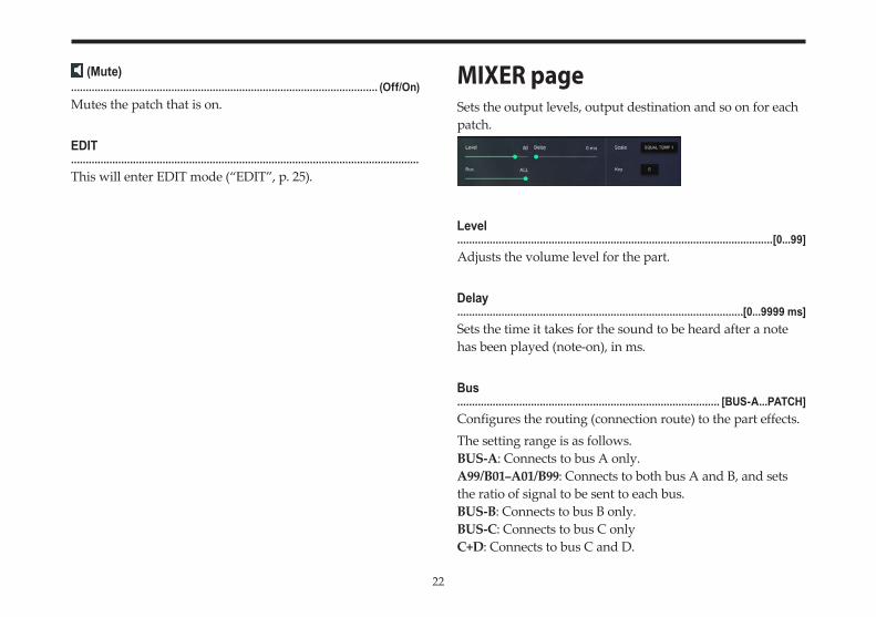
MIXER pageSets the output levels, output destination and so on for each patch.
Level...........................................................................................................[0...99]Adjusts the volume level for the part.
Delay.................................................................................................[0...9999 ms]Sets the time it takes for the sound to be heard after a note has been played (note-on), in ms.
Bus......................................................................................... [BUS-A...PATCH]Configures the routing (connection route) to the part effects.The setting range is as follows.BUS-A: Connects to bus A only.A99/B01–A01/B99: Connects to both bus A and B, and sets the ratio of signal to be sent to each bus.BUS-B: Connects to bus B only.BUS-C: Connects to bus C onlyC+D: Connects to bus C and D.
23
BUS-D: Connects to bus D only.ALL: Connects to all buses.PATCH: Connects to the bus configured in “FX BUS” on the EDIT and OUTPUT pages.
Scale (Scale Type)..............................................[EQUAL TEMP…PURE MINOR, USER 1...12]Sets the scale type (scale) for the patch.One of 16 different scale types can be selected.EQUAL TEMP 1: This is a widely used tuning, in which ev-ery semitone is spaced an equal pitch distance from the next (equal temperament tuning).EQUAL TEMP 2: In this tuning, the pitches of equal tem-perament tuning are randomly shifted with every note-on registered.PURE MAJOR: The notes of this tuning are completely har-monious with the major chords in the primary key specified (just intonation major scale).PURE MINOR: The notes of this tuning are completely har-monious with the minor chords in the primary key specified (just intonation minor scale).USER 1–12: The scale set in “User Scale”, SETTINGS mode will be used. One of 12 different user scales that were created can be selected (“SETTINGS”, p. 56).
Key (Root Key)............................................................................................................[C...B]When “PURE MAJOR” or “PURE MINOR” is selected in Scale, the primary chord key for the scale is set.
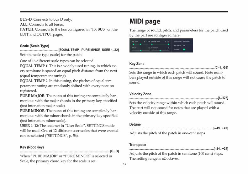
MIDI pageThe range of sound, pitch, and parameters for the patch used by the part are configured here.
Key Zone......................................................................................................[C–1...G9]Sets the range in which each patch will sound. Note num-bers played outside of this range will not cause the patch to sound.
Velocity Zone..........................................................................................................[1...127]Sets the velocity range within which each patch will sound. The part will not sound for notes that are played with a velocity outside of this range.
Detune.................................................................................................... [–49...+49]Adjusts the pitch of the patch in one-cent steps.
Transpose.....................................................................................................[–24...+24]Adjusts the pitch of the patch in semitone (100 cent) steps. The setting range is ±2 octaves.
24
Voice Mode................................................ [POLYPHONIC/UNI RETRIG/UNI LEGATO]Sets the sound mode for note-on signals received for each patch.Tap the setting to switch between the modes.POLYPHONIC: Multiple voices will sound simultaneously, up to the maximum polyphony.UNI RETRIG: All voices of this part will be stacked when a single note is played, and will be retriggered with each note-on.UNI LEGATO: All voices of this part will be stacked when a single note is played. When playing legato, the voices will not be retriggered with each new note played.
Key Priority.......................................................................................[LOW/HIGH/LAST]When receiving multiple note-on signals, this sets which key should be given priority to sound.Tap the setting to switch between the values.This is enabled only when “Voice Mode” is set to UNI RE-TRIG or UNI LEGATO.
Sustain........................................................................................................ (Off/On)Sets whether the patch responds to sustain.
25
EDITHow a Patch is structuredTraditional analog synthesizers produce sound by applying a low pass filter and amplifier to a basic waveform or noise.The iWAVESTATION provides thirty-two digital sound gen-erators, each consisting of a fully-digital oscillator, filter, am-plifier, plus two envelope generators and two LFOs. While fully utilizing the strengths of traditional analog synthesiz-ers, the iWAVESTATION delivers vastly more sophisticated and powerful sounds.
OscillatorsA patch can use either a single mode (only one oscillator), double mode (two oscillator), or quad mode (four oscillator). Larger numbers of oscillators let you create richer and more complex sounds. Using fewer oscillators will let you play a larger number of voices simultaneously. You can adjust the pitch of each oscillator in steps of one cent, over a range of eight octaves. Since you can also specify how each oscillator is assigned to the keyboard, you can set the range of keys for which an oscillator will sound, or even invert its tuning so that the pitch will descend as you play upward on the keyboard.
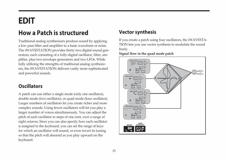
Vector synthesisIf you create a patch using four oscillators, the iWAVESTA-TION lets you use vector synthesis to modulate the sound freely.Signal flow in the quad mode patch
OSCILLATORFILTER AMP
AMP ENV
ENV1
LFO1 LFO2C
OSCILLATORFILTER AMP
AMP ENV
ENV1
LFO1 LFO2D
OSCILLATORFILTER AMP
AMP ENV
ENV1
LFO1 LFO2A
OSCILLATORFILTER AMP
AMP ENV
ENV1
LFO1 LFO2B
WAVESWAVE
SEQUENCES
PAN
D
A C
B
26
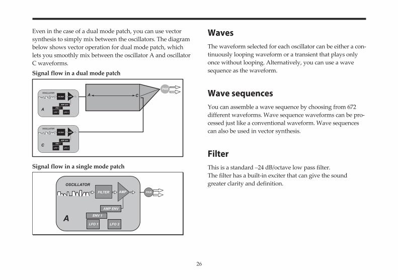
Even in the case of a dual mode patch, you can use vector synthesis to simply mix between the oscillators. The diagram below shows vector operation for dual mode patch, which lets you smoothly mix between the oscillator A and oscillator C waveforms.Signal flow in a dual mode patch
Signal flow in a single mode patch
WavesThe waveform selected for each oscillator can be either a con-tinuously looping waveform or a transient that plays only once without looping. Alternatively, you can use a wave sequence as the waveform.
Wave sequencesYou can assemble a wave sequence by choosing from 672 different waveforms. Wave sequence waveforms can be pro-cessed just like a conventional waveform. Wave sequences can also be used in vector synthesis.
FilterThis is a standard –24 dB/octave low pass filter.The filter has a built-in exciter that can give the sound greater clarity and definition.
OSCILLATOR
FILTER AMP
AMP ENV
ENV 1
LFO 1 LFO 2C
COSCILLATOR
FILTER AMP
AMP ENV
ENV 1
LFO 1 LFO 2A
APAN
PAN
OSCILLATOR
FILTER AMP
AMP ENV
ENV 1
LFO 1 LFO 2A
27
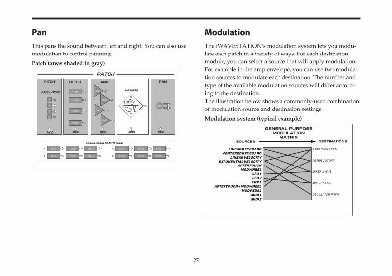
PanThis pans the sound between left and right. You can also use modulation to control panning.Patch (areas shaded in gray)
ModulationThe iWAVESTATION’s modulation system lets you modu-late each patch in a variety of ways. For each destination module, you can select a source that will apply modulation.For example in the amp envelope, you can use two modula-tion sources to modulate each destination. The number and type of the available modulation sources will differ accord-ing to the destination.The illustration below shows a commonly-used combination of modulation source and destination settings.Modulation system (typical example)
AMPLIFIER LEVEL
FILTER CUTOFF
MIXER X-AXIS
MIXER Y-AXIS
OSCILLATOR PITCH
28
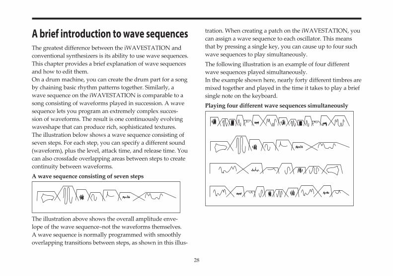
A brief introduction to wave sequencesThe greatest difference between the iWAVESTATION and conventional synthesizers is its ability to use wave sequences. This chapter provides a brief explanation of wave sequences and how to edit them.On a drum machine, you can create the drum part for a song by chaining basic rhythm patterns together. Similarly, a wave sequence on the iWAVESTATION is comparable to a song consisting of waveforms played in succession. A wave sequence lets you program an extremely complex succes-sion of waveforms. The result is one continuously evolving waveshape that can produce rich, sophisticated textures.The illustration below shows a wave sequence consisting of seven steps. For each step, you can specify a different sound (waveform), plus the level, attack time, and release time. You can also crossfade overlapping areas between steps to create continuity between waveforms.A wave sequence consisting of seven steps
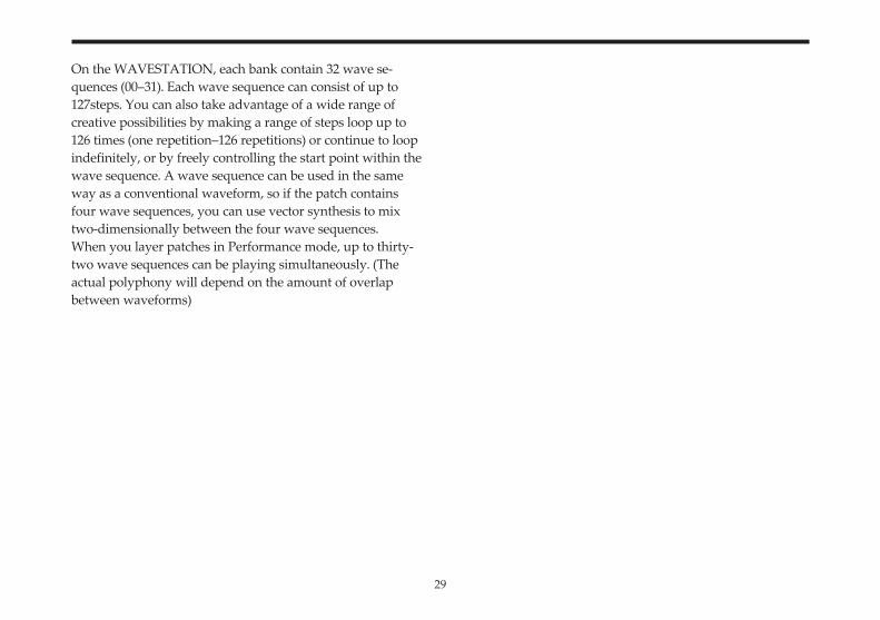
The illustration above shows the overall amplitude enve-lope of the wave sequence–not the waveforms themselves. A wave sequence is normally programmed with smoothly overlapping transitions between steps, as shown in this illus-
tration. When creating a patch on the iWAVESTATION, you can assign a wave sequence to each oscillator. This means that by pressing a single key, you can cause up to four such wave sequences to play simultaneously.The following illustration is an example of four different wave sequences played simultaneously.In the example shown here, nearly forty different timbres are mixed together and played in the time it takes to play a brief single note on the keyboard.Playing four different wave sequences simultaneously
29
On the WAVESTATION, each bank contain 32 wave se-quences (00–31). Each wave sequence can consist of up to 127steps. You can also take advantage of a wide range of creative possibilities by making a range of steps loop up to 126 times (one repetition–126 repetitions) or continue to loop indefinitely, or by freely controlling the start point within the wave sequence. A wave sequence can be used in the same way as a conventional waveform, so if the patch contains four wave sequences, you can use vector synthesis to mix two-dimensionally between the four wave sequences.When you layer patches in Performance mode, up to thirty-two wave sequences can be playing simultaneously. (The actual polyphony will depend on the amount of overlap between waveforms)
30
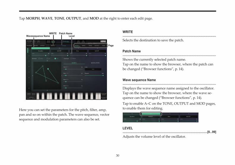
Tap MORPH, WAVE, TONE, OUTPUT, and MOD at the right to enter each edit page.
Here you can set the parameters for the pitch, filter, amp, pan and so on within the patch. The wave sequence, vector sequence and modulation parameters can also be set.
WRITE......................................................................................................................Selects the destination to save the patch.
Patch Name......................................................................................................................Shows the currently selected patch name.Tap on the name to show the browser, where the patch can be changed (“Browser functions”, p. 14).
Wave sequence Name......................................................................................................................Displays the wave sequence name assigned to the oscillator.Tap on the name to show the browser, where the wave se-quence can be changed (“Browser functions”, p. 14).Tap to enable A–C on the TONE, OUTPUT and MOD pages, to enable them for editing.
LEVEL...........................................................................................................[0...99]Adjusts the volume level of the oscillator.
Page
WRITE Patch NameWavesequence Name Level
31
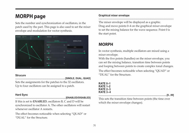
MORPH pageSets the number and synchronization of oscillators, in the patch used by the part. This page is also used to set the mixer envelope and modulation for vector synthesis.
Strucure.............................................................................. [SINGLE, DUAL, QUAD]Sets the assignments for the patches to the 32 oscillators.Up to four oscillators can be assigned to a patch.
Hard Sync............................................................................... [ENABLED/DISABLED]If this is set to ENABLED, oscillators B, C and D will be synchronized to oscillator A. The other oscillators will restart whenever oscillator A restarts.The effect becomes noticeable when selecting “QUAD” or “DUAL” for the Structure.
Graphical mixer envelope......................................................................................................................The mixer envelope will be displayed as a graphic.Drag and move points 0–4 on the graphical mixer envelope to set the mixing balance for the wave sequence. Point 0 is the start point.
MORPHIn vector synthesis, multiple oscillators are mixed using a mixer envelope.With the five points (handles) on the mixer envelope, you can set the mixing balance, transition time between points and looping between points to create complex tonal changes.The effect becomes noticeable when selecting “QUAD” or “DUAL” for the Structure.
RATE 0–1RATE 1–2RATE 2–3RATE 3–4...........................................................................................................[0...99]This sets the transition time between points (the time over which the mixer envelope changes).
32
Loop......................................................................................... [OFF, 0→3...2↔3]Normally, if a note-off is not received after receiving a note-on, the oscillator mix ratio will remain at the settings of point 3. When using the loop function, you will be able to change the mix ratio while the note is sounding by changing the distance between point 3 and the points before it.
Repeats..........................................................................................[OFF, 1...127, INF]When Loop is set to a value besides OFF, the number of times the loop will occur can be set.
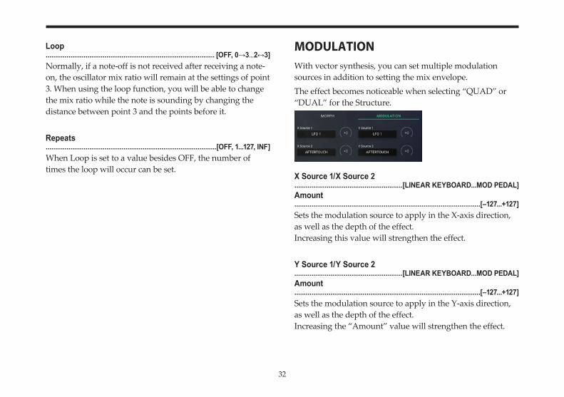
MODULATIONWith vector synthesis, you can set multiple modulation sources in addition to setting the mix envelope.The effect becomes noticeable when selecting “QUAD” or “DUAL” for the Structure.
X Source 1/X Source 2.........................................................[LINEAR KEYBOARD...MOD PEDAL]Amount..................................................................................................[–127...+127]Sets the modulation source to apply in the X-axis direction, as well as the depth of the effect.Increasing this value will strengthen the effect.
Y Source 1/Y Source 2.........................................................[LINEAR KEYBOARD...MOD PEDAL]Amount..................................................................................................[–127...+127]Sets the modulation source to apply in the Y-axis direction, as well as the depth of the effect.Increasing the “Amount” value will strengthen the effect.
33
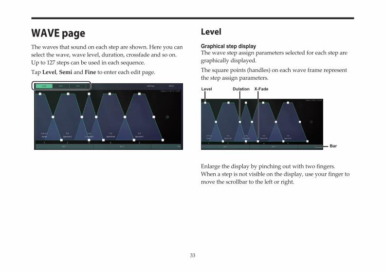
WAVE pageThe waves that sound on each step are shown. Here you can select the wave, wave level, duration, crossfade and so on. Up to 127 steps can be used in each sequence.Tap Level, Semi and Fine to enter each edit page.
LevelGraphical step displayThe wave step assign parameters selected for each step are graphically displayed.The square points (handles) on each wave frame represent the step assign parameters.
Enlarge the display by pinching out with two fingers.When a step is not visible on the display, use your finger to move the scrollbar to the left or right.
Level Dulation X-Fade
Bar
34
Level...........................................................................................................[0...99]Drag a point up and down to set the volume levels at which the waves in the steps sound.
note This setting is also reflected in the PARAM pages on WAVESEQ (“PARAM page”, p. 19).
Duration............................................................................................... [1...499, Gate]Drag a point to the left and right to set the time (clock) at which the step sounds.The available values are 1–499 and “Gate” (the time between receiving a note-on and a note-off).
If the value exceeds the actual length of the wave that sounds, no sound will be heard during the portion that exceeds the length of the wave. If the setting is “Gate”, the sequence will not proceed to the next step.
If the tempo setting in Tempo Source is “Internal”, the wave sequence will sound using the set tempo. If “MIDI Clock” is used, the wave sequence will sound according to the MIDI clocks sent to the application (“Internal/MIDI Clock”, p. 58). For the settings used to transmit MIDI clocks, refer to the user’s manual for the application that will be transmitting the data.
X-Fade (Crossfade).........................................................................................................[0...998]Here you can set the amount of overlap between the end of a step and the beginning of the next one, by dragging the points to the left and right.The actual overlap amounts are determined by the “Dura-tion” and “X-Fade” values.
Selecting the wavesYou can tap on a wave to show the WAVE browser and select the wave (“Selecting Wave sequences, Paches, and Waves”, p. 15).
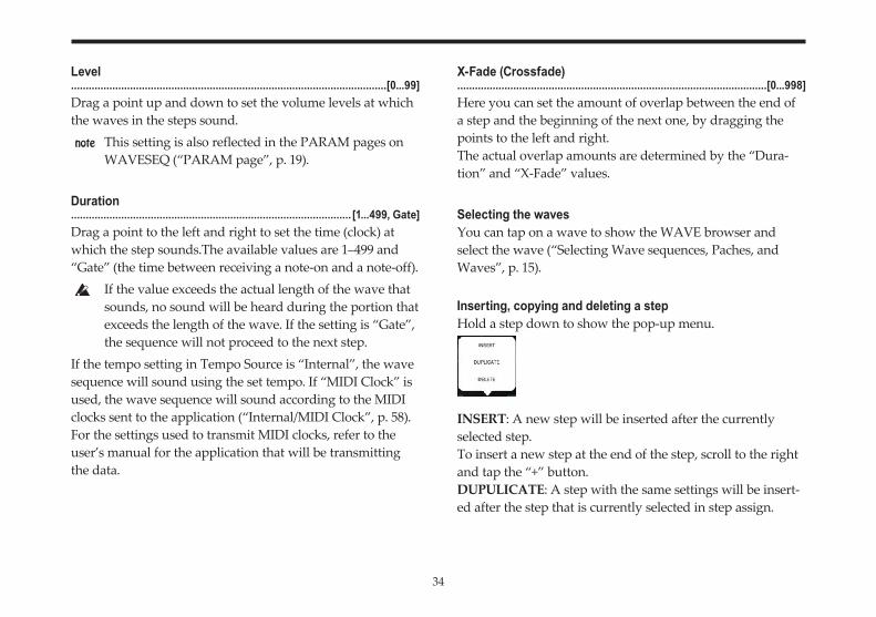
Inserting, copying and deleting a stepHold a step down to show the pop-up menu.
INSERT: A new step will be inserted after the currently selected step.To insert a new step at the end of the step, scroll to the right and tap the “+” button.DUPULICATE: A step with the same settings will be insert-ed after the step that is currently selected in step assign.
35
DELETE: The step that is currently selected in step assign will be deleted.Hold down the waveform, and tap DELETE on the pop-up menu that is displayed.
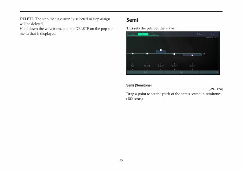
SemiThis sets the pitch of the wave.
Semi (Semitone).....................................................................................................[–24...+24]Drag a point to set the pitch of the step’s sound in semitones (100 cents).
36
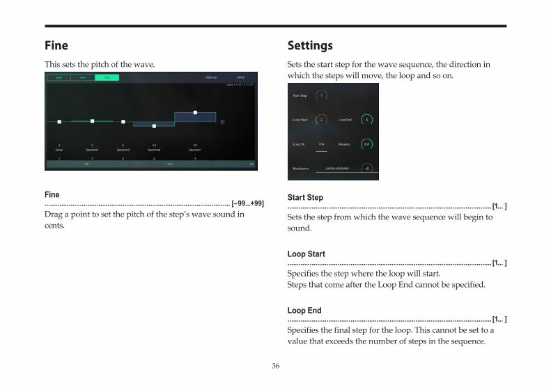
FineThis sets the pitch of the wave.
Fine.................................................................................................... [–99...+99]Drag a point to set the pitch of the step’s wave sound in cents.
SettingsSets the start step for the wave sequence, the direction in which the steps will move, the loop and so on.
Start Step.............................................................................................................. [1... ]Sets the step from which the wave sequence will begin to sound.
Loop Start.............................................................................................................. [1... ]Specifies the step where the loop will start. Steps that come after the Loop End cannot be specified.
Loop End.............................................................................................................. [1... ]Specifies the final step for the loop. This cannot be set to a value that exceeds the number of steps in the sequence.
37
Loop Dir (Loop Direction)...................................................................................[FOR (Forward), B/F]Configures the loop for the step.FOR: The loop will repeat from the “Loop Start” to “Loop End”, for as many times as is set in “Repeats”.B/F: Once the step specified by the “Loop End” is reached, the loop will run backwards towards the “Loop Start”.
Repeats......................................................................................... [OFF, 1...126, INF]Sets the number of times the loop repeats.1–126: Even if a note-off is received, the loop of the wave se-quence will repeat as many times as specified in the settings, and will then play according to its programming.OFF: Even if a note-off is received, the loop of the wave se-quence will repeat as many times as specified in the settings, and will then play according to the program.INF: The sequence will continue to loop until the amp EG finishes its release segment.
Modulation (Modulation Source).........................................................[LINEAR KEYBOARD...MOD PEDAL]Amount..................................................................................................[–127...+127]These parameters specify the source and depth of the modu-lation that can be applied to the wave sequence.The way in which the wave sequence is modulated will depend on the modulation source you select.
If Modulation is set to “LINEAR KEYBOARD”–“EXP VE-LOCITY”, and you (for example) play the keyboard of an external MIDI device connected to your computer, the wave sequence will start from a different step depending on the key position or velocity of the note-on message. The distance from the Start step will depend on the “Amount.” Once the wave sequence starts, it will play normally until you release the note or the sequence ends.If Modulation is set to “LFO 1”–“MOD PEDAL”, the wave sequence will not play according to the durations specified for each step. Instead, it will play from the Start step accord-ing to the speed and direction at which you move the modu-lation source.For example, suppose that you set Start Step to “13” and set Modulation to “MOD WHEEL”. If you play a note-on while the modulation wheel is in the downward position (toward yourself), the waveform assigned to step 13 will continue playing. (If it’s a transient waveform, it will play only once.) If you then move the modulation wheel upward (away from yourself), successive steps of the wave sequence will begin sounding.If the Loop Direction is “B/F”, you can operate the modula-tion wheel to move forward or backward through the steps.
38
WriteWriting a wave sequence......................................................................................................................This writes (updates) a wave sequence to memory that has been edited.On the iWAVESTATION, this writes the edited wave se-quence to the memory of cards USER 1–USER 3.Tap to show the pop-up menu, and then select the wave sequence to write to. Change the name if necessary, and save the wave sequence.
TONE page
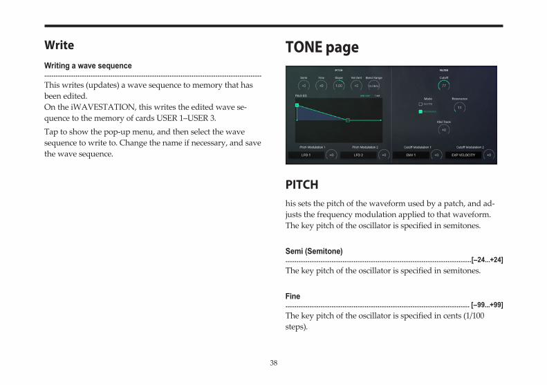
PITCHhis sets the pitch of the waveform used by a patch, and ad-justs the frequency modulation applied to that waveform.The key pitch of the oscillator is specified in semitones.
Semi (Semitone).....................................................................................................[–24...+24]The key pitch of the oscillator is specified in semitones.
Fine.................................................................................................... [–99...+99]The key pitch of the oscillator is specified in cents (1/100 steps).
39
Slope...............................................................................................[–2.00...+2.00]Sets the key slope.+1.00 is the standard setting.When this is set to +2.00, the note messages within a one-octave range will be shifted over a two-octave scale.When this is set to 0.00, all note messages will produce a C4 sound.When this is set to a negative value, the scale for note mes-sages will be reversed.
Velo Amt (Velocity Amount)..................................................................................................[–127...+127]Sets the sensitivity of the “Time (Ramp Time)” for the veloc-ity.When the value is 0, the “Time” will not be affected. With positive (+) settings, the pitch will return to its normal pitch more quickly when you play strongly (i.e., with higher velocities). With negative (–) settings, the pitch will return to its normal pitch more slowly when you play strongly.
BEND RANGE..................................................................................[GLOBAL, OFF, 1...12]This sets the pitch bend range.
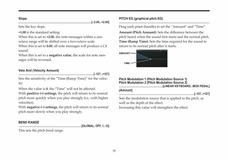
PITCH EG (graphical pitch EG)......................................................................................................................Drag each point (handle) to set the “Amount” and “Time”.Amount (Pitch Amount): Sets the difference between the pitch heard when the sound first starts and the normal pitch.Time (Ramp Time): Sets the time required for the sound to return to its normal pitch after it starts.
Pitch Modulation 1 (Pitch Modulation Source 1)Pitch Modulation 2 (Pitch Modulation Source 2).........................................................[LINEAR KEYBOARD...MOD PEDAL](Amount)..................................................................................................[–127...+127]Sets the modulation source that is applied to the pitch, as well as the depth of the effect.Increasing this value will strengthen the effect.
TIME
AMOUNT
40
FILTERThis is a standard −24dB/octave low-pass filter.You can use various modulation sources to add modulation.
Cutoff...........................................................................................................[0...99]Sets the cutoff frequency. Higher values will produce a brighter sound.
Mode............................................................................ [EXCITER/RESONANCE](Amount)...........................................................................................................[0...99]Select EXCITER or RESONANCE for the mode, and set the value.EXCITER: This adjusts the high-frequency region. Higher settings will give the high-frequency region more sparkle and clarity.RESONANCE: This will emphasize the overtone spectrum near the cutoff frequency, adding a distinctive character to the sound. Higher settings will emphasize the overtones, increasing the resonance effect.
note This setting is also reflected in the PARAM pages on WAVESEQ (“PARAM page”, p. 19).
Kbd Track..................................................................................................[–127...+127]This controls how the cutoff frequency changes in response to note data (the pitch of the note) received.With positive (+) settings, the sound will be brighter as you play higher on the keyboard.With negative (–) settings, the sound will be brighter as you play lower on the keyboard.
Cutoff Modulation 1 (Cutoff Modulation Source 1)Cutoff Modulation 2 (Cutoff Modulation Source 2).........................................................[LINEAR KEYBOARD...MOD PEDAL](Amount)..................................................................................................[–127...+127]Sets the modulation source that is applied to the cutoff frequency, as well as the depth of the effect. Increasing this value will strengthen the effect.
41
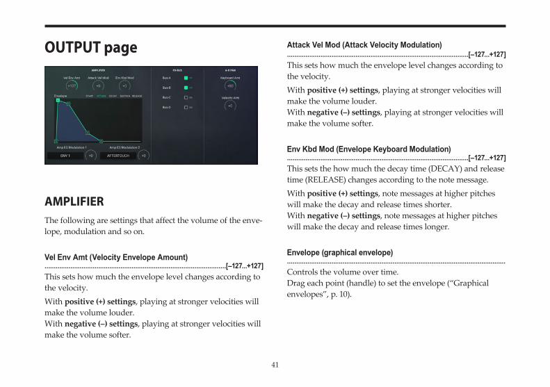
OUTPUT page
AMPLIFIERThe following are settings that affect the volume of the enve-lope, modulation and so on.
Vel Env Amt (Velocity Envelope Amount)..................................................................................................[–127...+127]This sets how much the envelope level changes according to the velocity.With positive (+) settings, playing at stronger velocities will make the volume louder.With negative (–) settings, playing at stronger velocities will make the volume softer.
Attack Vel Mod (Attack Velocity Modulation)..................................................................................................[–127...+127]This sets how much the envelope level changes according to the velocity.With positive (+) settings, playing at stronger velocities will make the volume louder.With negative (–) settings, playing at stronger velocities will make the volume softer.
Env Kbd Mod (Envelope Keyboard Modulation)..................................................................................................[–127...+127]This sets the how much the decay time (DECAY) and release time (RELEASE) changes according to the note message.With positive (+) settings, note messages at higher pitches will make the decay and release times shorter.With negative (–) settings, note messages at higher pitches will make the decay and release times longer.
Envelope (graphical envelope)......................................................................................................................Controls the volume over time.Drag each point (handle) to set the envelope (“Graphical envelopes”, p. 10).
42
Amp EG Modulation 1 (Amp EG Modulation Source 1)Amp EG Modulation 2 (Amp EG Modulation Source 2).........................................................[LINEAR KEYBOARD...MOD PEDAL](Amount)..................................................................................................[–127...+127]Sets the modulation source that is applied to the amp EG, as well as the depth of the effect.
FX-BUSConfigures the routing to the patch effects.
Bus-A/B/C/D..................................................................................................... [ON, OFF]When this is ON, the envelope will be connected to the effect input.
A-B PANConfigures the routing to the patch effects, as well as the modulation to apply to the pan settings in the “FX BUS”.
Keyboard Amt (Keyboard Amount)..................................................................................................[–127...+127]Specifies the depth and direction in which the note number (keyboard position) will affect panning.With positive (+) settings, higher note numbers will be out-put further toward the left and lower note numbers will be output further toward the right.
Velocity Amt (Velocity Amount)..................................................................................................[–127...+127]This sets the depth of the modulation applied to the panning through velocity.With positive (+) settings, playing at lower velocities will output the note using the pan settings in “FX Bus”, Perfor-mance Edit, DETAIL. Playing at higher velocities will output the note using bus B (BUS-B).With negative (–) settings, the opposite will occur.With a setting of 0, the velocity will have no effect.
43
MOD page
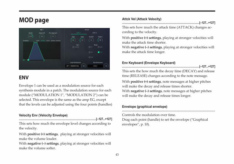
ENVEnvelope 1 can be used as a modulation source for each synthesis module in a patch. The modulation source for each module (“MODULATION 1”, “MODULATION 2”) can be selected. This envelope is the same as the amp EG, except that the levels can be adjusted using the four points (handles)
Velocity Env (Velocity Envelope)..................................................................................................[–127...+127]This sets how much the envelope level changes according to the velocity.With positive (+) settings, playing at stronger velocities will make the volume louder.With negative (–) settings, playing at stronger velocities will make the volume softer.
Attck Vel (Attack Velocity)..................................................................................................[–127...+127]This sets how much the attack time (ATTACK) changes ac-cording to the velocity.With positive (+) settings, playing at stronger velocities will make the attack time shorter.With negative (–) settings, playing at stronger velocities will make the attack time longer.
Env Keyboard (Envelope Keyboard)..................................................................................................[–127...+127]This sets the how much the decay time (DECAY) and release time (RELEASE) changes according to the note message.With positive (+) settings, note messages at higher pitches will make the decay and release times shorter.With negative (–) settings, note messages at higher pitches will make the decay and release times longer.
Envelope (graphical envelope)......................................................................................................................Controls the modulation over time.Drag each point (handle) to set the envelope (“Graphical envelopes”, p. 10).
44
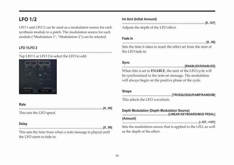
LFO 1/2LFO 1 and LFO 2 can be used as a modulation source for each synthesis module in a patch. The modulation source for each module (“Modulation 1”, “Modulation 2”) can be selected.
LFO 1/LFO 2......................................................................................................................Tap LFO 1 or LFO 2 to select the LFO to edit.
Rate...........................................................................................................[0...99]This sets the LFO speed.
Delay...........................................................................................................[0...99]This sets the time from when a note message is played until the LFO starts to fade in.
Int Amt (Initial Amount)......................................................................................................... [0...127]Adjusts the depth of the LFO effect.
Fade In...........................................................................................................[0...99]Sets the time it takes to reach the effect set from the start of the LFO fade-in.
Sync............................................................................... [ENABLED/DISABLED]When this is set to ENABLE, the start of the LFO cycle will be synchronized to the note-on message. The modulation will always begin on the positive phase of the cycle.
Shape............................................................... [TRI/SQU/SQU/RAMP/RANDOM]This selects the LFO waveform.
Depth Modulation (Depth Modulation Source).......................................................... [LINEAR KEYBOARD/MOD PEDAL](Amount)..................................................................................................[–127...+127]Sets the modulation source that is applied to the LFO, as well as the depth of the effect.
45
Rate Modulation (Rate Modulation Source).......................................................... [LINEAR KEYBOARD/MOD PEDAL](Amount)..................................................................................................[–127...+127]Sets the modulation source that is applied to the LFO in pro-portion to the LFO “Rate”, as well as the depth of the effect.
46
EFFECTSEffect systemThe iWAVESTATION contains two completely indepen-dent stereo multi-effect units, Effect 1 (FX 1) and Effect 2 (FX 2). Each provides fifty-five different effects such as reverb, delay, and distortion.The iWAVESTATION lets you route FX 1 and FX 2 either in parallel or in series. In addition, you can edit the effect settings for each part, or make settings for a specific part to bypass FX 1 and FX 2 and apply an external effect. You can also assign effects to different sounds, and mix the result for output.Effect settings are made in two stages. First, specify the effect types for FX 1 and FX 2, and specify either series or parallel placement.Then you can edit the parameters of each effect. The effect parameters differ depending on the effect you selected. For details on the effect types, refer to “Effect list” (p. 50).The combination of effects can be specified independently for each performance.
Effect structureThe effect system consists of four inputs (A, B, C, D), two effect units (FX 1, FX 2), and two mixers (Mix C, Mix D). Two effect outputs (1/L, 2/R) are provided. To route patches to the effects, use the “FX-BUS” settings in the Performance Edit page. Input settings, settings for each effect, and output settings are made in the Effect Edit page. The inputs and outputs of the two effect units can be connected in either parallel or series.
47
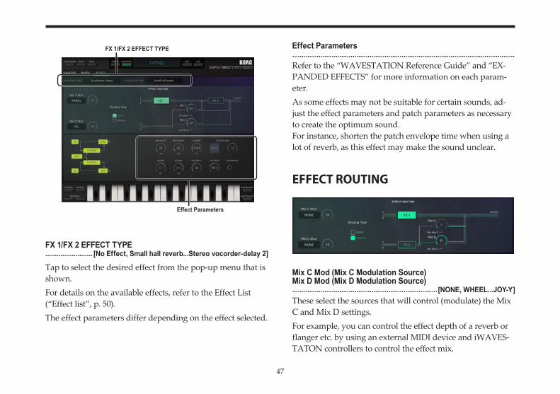
FX 1/FX 2 EFFECT TYPE......................... [No Effect, Small hall reverb...Stereo vocorder-delay 2]
Tap to select the desired effect from the pop-up menu that is shown.For details on the available effects, refer to the Effect List (“Effect list”, p. 50).The effect parameters differ depending on the effect selected.
Effect Parameters......................................................................................................................Refer to the “WAVESTATION Reference Guide” and “EX-PANDED EFFECTS” for more information on each param-eter.As some effects may not be suitable for certain sounds, ad-just the effect parameters and patch parameters as necessary to create the optimum sound.For instance, shorten the patch envelope time when using a lot of reverb, as this effect may make the sound unclear.
EFFECT ROUTING
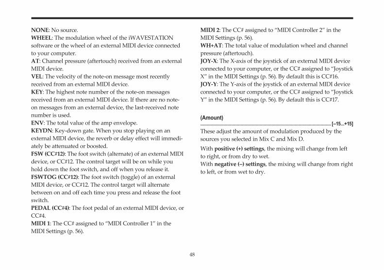
Mix C Mod (Mix C Modulation Source)Mix D Mod (Mix D Modulation Source).............................................................................[NONE, WHEEL...JOY-Y]These select the sources that will control (modulate) the Mix C and Mix D settings.For example, you can control the effect depth of a reverb or flanger etc. by using an external MIDI device and iWAVES-TATON controllers to control the effect mix.
FX 1/FX 2 EFFECT TYPE
Effect Parameters
48
NONE: No source.WHEEL: The modulation wheel of the iWAVESTATION software or the wheel of an external MIDI device connected to your computer.AT: Channel pressure (aftertouch) received from an external MIDI device.VEL: The velocity of the note-on message most recently received from an external MIDI device.KEY: The highest note number of the note-on messages received from an external MIDI device. If there are no note-on messages from an external device, the last-received note number is used.ENV: The total value of the amp envelope.KEYDN: Key-down gate. When you stop playing on an external MIDI device, the reverb or delay effect will immedi-ately be attenuated or boosted.FSW (CC#12): The foot switch (alternate) of an external MIDI device, or CC#12. The control target will be on while you hold down the foot switch, and off when you release it.FSWTOG (CC#12): The foot switch (toggle) of an external MIDI device, or CC#12. The control target will alternate between on and off each time you press and release the foot switch.PEDAL (CC#4): The foot pedal of an external MIDI device, or CC#4.MIDI 1: The CC# assigned to “MIDI Controller 1” in the MIDI Settings (p. 56).
MIDI 2: The CC# assigned to “MIDI Controller 2” in the MIDI Settings (p. 56).WH+AT: The total value of modulation wheel and channel pressure (aftertouch).JOY-X: The X-axis of the joystick of an external MIDI device connected to your computer, or the CC# assigned to “Joystick X” in the MIDI Settings (p. 56). By default this is CC#16.JOY-Y: The Y-axis of the joystick of an external MIDI device connected to your computer, or the CC# assigned to “Joystick Y” in the MIDI Settings (p. 56). By default this is CC#17.
(Amount)..................................................................................................... [–15...+15]These adjust the amount of modulation produced by the sources you selected in Mix C and Mix D.With positive (+) settings, the mixing will change from left to right, or from dry to wet.With negative (–) settings, the mixing will change from right to left, or from wet to dry.
49
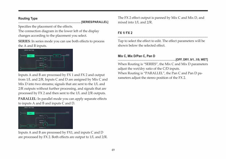
Routing Type.................................................................................. [SERIES/PARALLEL]Specifies the placement of the effects.The connection diagram in the lower left of the display changes according to the placement you select.SERIES: In series mode you can use both effects to process the A and B inputs.
Inputs A and B are processed by FX 1 and FX 2 and output from 1/L and 2/R. Inputs C and D are assigned by Mix C and Mix D into two streams; signals that are sent to the 1/L and 2/R outputs without further processing, and signals that are processed by FX 2 and then sent to the 1/L and 2/R outputs.PARALLEL: In parallel mode you can apply separate effects to inputs A and B and inputs C and D.
Inputs A and B are processed by FX1, and inputs C and D are processed by FX 2. Both effects are output to 1/L and 2/R.
The FX 2 effect output is panned by Mix C and Mix D, and mixed into 1/L and 2/R.
FX 1/ FX 2......................................................................................................................Tap to select the effect to edit. The effect parameters will be shown below the selected effect.
Mix C, Mix D/Pan C, Pan D............................................................................[OFF, DRY, 9/1...1/9, WET]When Routing is “SERIES”, the Mix C and Mix D parameters adjust the wet/dry ratio of the C/D inputs.When Routing is “PARALLEL”, the Pan C and Pan D pa-rameters adjust the stereo position of the FX 2.
50
Effect list
No EffectNo effect will be used.
Reverb - EQSmall hall reverbReverb simulating a broad space such as a hall. This effect has a relatively short reverb time, and produces a fairly bright reverberation.
Medium hall reverbReverb with more depth than Small Hall, with an emphasis on the short early reflections.
Large hall reverbReverb simulating the natural reverberation of a concert hall.
Small room reverbSimulation of a small room, emphasizing the depth of the sound.
Large room reverbSimulation of a large room.
Live StageProduces a somewhat broader effect than Room Reverb.
Wet plate reverbDeeply applied plate reverb.
Dry plate reverbLightly applied plate reverb.
Spring reverbSimulates a reverb unit that uses a spring mechanism.
Early ReflectionsEarly reflections 1This can be used to produce a gated effect, or to add depth to the sound.
Early reflections 2The level of early reflections differs from Early Reflections 1.
Early reflections 3A backward envelope is applied to the early reflections.
51
Gate reverb - EQForward gated reverbThese effects apply a gate to only the early reflection compo-nents.You can adjust the gate hold time.
Reverse gated reverbThese effects apply a reverse gate to only the early reflection components.You can adjust the gate hold time.
Stereo delayStereo delayThis is a stereo delay with feedback. The delay times of the left and right channels is determined by the left/right ratio. The input level adjusts the decay characteristics.
Ping - pong delayThis is a stereo delay in which two delayed channels are fed back to each other, causing the delayed sound to alternate between left and right.
Dual mono delayDual mono delayThis produces two channels of monaural delay.
Stereo multi-tap delay EQMulti-tap delay 1The input level determines how the delay is repeated.
Multi-tap delay 2Panning and repeats are adjusted by the input level.
Multi-tap delay 3This produces two channels of delay that feed back to each other. The input level determines how the delay is repeated.
Stereo chorus - EQStereo chorusA stereo chorus in which the LFOs applied to each channel are 180°out-of-phase.
Quadrature chorusA stereo chorus in which the LFOs applied to each channel are 90° out-of-phase.
Crossover chorusA stereo chorus in which the two channels apply quadrature chorus to each other.
52
Stereo harmonic chorusStereo harmonic chorusThis is the same effect as Quadrature chorus, but a frequency splitter is used to apply chorus only to the high-frequency region.
Stereo flanger - EQStereo flanger 1A stereo flanger in which in-phase LFOs are applied to the two channels.
Stereo flanger 2A stereo flanger in which out-of-phase LFOs are applied to the two channels.
Crossover flangerFlangers with in-phase LFOs are applied, with the two chan-nels feeding-back to each other.
Stereo enhancer/exciter - EQStereo enhancerThis effect adds sparkle to the sound. It includes a short ste-reo delay.
Distortion/filter - EQDistortionThis effect causes the sound to distort. It is effective on guitar solos and similar sounds.
OverdriveThis simulates a guitar overdrive effect.
Stereo phaserStereo phaser 1A phaser in which in-phase LFOs are applied to the two channels.
Stereo phaser 2A phaser in which out-of-phase LFOs are applied to the two channels.
Stereo rotary speakerStereo rotary speakerThis effect simulates the rotating speaker traditionally used on “tonewheel” organs. The Slow/Fast speed can be specified by “ACCELERATION.” In this case, you can use an external MIDI device connected to your computer to switch the speed of rotation.
53
Modulation - Pan - EQThese effects apply panning to the input, and output it in stereo. They also allow you to mix the panned output with an equalized effect input.
Stereo modIn-phase LFOs are used to apply stereo panning.
QuadratureLFOs that are 90 degrees out-of-phase are used to apply stereo panning.
EqualizerStereo parametric equalizerThis is a three-band equalizer. You can produce a wah effect by controlling (modulating) the center frequency.
Mono chorus, flanger/delayEffects are mono-in/stereo-out chorus and flanger effects with a stereo delay applied. These effects also provide a sam-ple/hold function that causes the delay to continue repeating.
Chorus-stereo delayThe output of a mono-in/stereo-out chorus is sent through a stereo delay that provides a sample/hold function.
Flanger-stereo delayThe output of a mono-in/stereo-out flanger is sent through a stereo delay that provides a sample/hold function.
Mono delay/reverbDelay/hallThis combines a mono delay and a mono hall reverb.
Delay/roomThis combines a mono delay and a mono room reverb.
Mono delay/mono chorus, flangerDelay/chorusThis combines a mono delay and a mono chorus.
Delay/flangerThis combines a mono delay and a mono flanger.
54
Mono delay/distortion, overdriveDelay/distortionThis combines a mono delay with distortion that includes a wah effect.
Delay/overdriveThis combines a mono delay with overdrive that includes a wah effect.
Mono delay/phaserDelay/phaserThis combines a mono delay and a mono phaser.
Mono delay/rotaryDelay/rotaryThis combines a mono delay with a mono rotary speaker.
Stereo pitch shifterPitch shifterThis is a stereo pitch shifter in which the left channel is shifted up and the right channel is shifted down. Applying a slight shift can create a distinctively different chorus effect.
Modulatable pitch shifterModulatable pitch shifterThis stereo pitch shifter applies modulation to the pitch-shifted sound. After the input signal is shifted up or down, a delay is applied to the pitch-shifted signal. The amount of feedback can also be adjusted.
Stereo compressor/limiter gateStereo compressor/Limiter A compressor automatically controls the volume of the input signal. It can be used to make the input signal level more consistent (particularly effective on guitar) or to give the sound more punch (e.g., when applied to drums).
55
Small vocoderA vocoder applies the spectral character of one signal (the “modulator”) to a different signal (the “carrier”). Vocoders of the past were used mainly to apply a talking or singing vocal character to a sound, but the iWAVESTATION lets you cre-ate completely new types of sound.
Small vocoder 1This vocoder uses the low through mid-high frequency regions. It is particular effective on lower-pitched sounds.
Small vocoder 2This vocoder uses the low-mid through high frequency regions. It is particular effective on higher-pitched sounds.
Small vocoder 3This vocoder uses a large number of equally-spaced frequen-cy bands that cover the low to mid-high frequency regions.
Small vocoder 4This vocoder uses a large number of equally-spaced frequen-cy bands that cover the low-mid to high frequency regions.
Stereo vocoder/delayThe stereo vocoder/delay effects are constructed from an ex-tremely powerful algorithm, and use both effect processors simultaneously.
Stereo Vocoder/Delay can be selected only for FX 1. Also, if you select Stereo Vocoder/Delay for FX1, no effect can be used for FX 2. (The display will indicate NO EFFECT.)
Stereo vocoder-delay 1This stereo vocoder uses wide low-range and high-range frequency bands, and a large number of narrow bands that cover the mid-frequency range.
Stereo vocoder-delay 2This stereo vocoder uses a large number of equally-spaced frequency bands that cover the entire frequency spectrum.
56
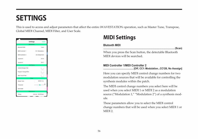
SETTINGSThis is used to access and adjust parameters that affect the entire iWAVESTATION operation, such as Master Tune, Transpose, Global MIDI Channel, MIDI Filter, and User Scale.
MIDI SettingsBlutooth MIDI........................................................................................................... (Scan)When you press the Scan button, the detectable Bluetooth MIDI devices will be searched.
MIDI Controller 1/MIDI Controller 2............................................. [Off, CC1: Modulation...CC126, No Asssign]
Here you can specify MIDI control change numbers for two modulation sources that will be available for controlling the synthesis modules within the patch.The MIDI control change numbers you select here will be used when you select MIDI 1 or MIDI 2 as a modulation source (“Modulation 1,” “Modulation 2”) of a synthesis mod-ule.These parameters allow you to select the MIDI control change numbers that will be used when you select MIDI 1 or MIDI 2.
57
Joystick-X/Joystick-Y............................................[Off, CC1: Modulation...CC95: Phaser Depth]This assigns a CC# to the X-axis (AXIS A–C) and Y-axis (AXIS B–D) of the Vector joystick.The default settings are X: CC#16 and Y: CC#17
MIDI FilteringControl Change Filter...................................................................................................... [OFF/ON]Selects whether MIDI control change messages will be re-ceived.OFF: Messages will be received.ON: Messages will not be received.
Program Change Filter...................................................................................................... [OFF/ON]Specifies whether MIDI program changes will be received.OFF: Messages will be received.ON: Messages will not be received.
After Touch Filter...................................................................................................... [OFF/ON]Specifies whether aftertouch will be received via MIDI.OFF: Messages will be received.ON: Messages will not be received.
TuningMaster Tune......................................................................................[420.00...460.00 Hz]Adjusts the overall pitch in steps of 0.1 Hz, specified as the basic pitch of the A4 note (Concert A).
Transpose.....................................................................................................[–24...+24]Adjusts the overall pitch of the performance played by the iWAVESTATION in units of a semitone (100 cents). The range is ±2 octaves.
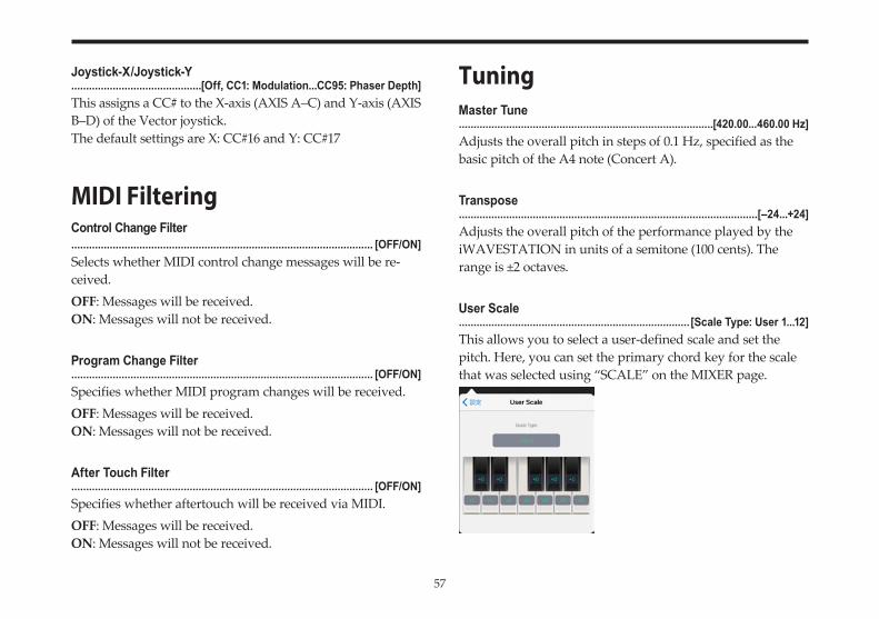
User Scale.............................................................................. [Scale Type: User 1...12]This allows you to select a user-defined scale and set the pitch. Here, you can set the primary chord key for the scale that was selected using “SCALE” on the MIXER page.
58
Select User 1–12, and set the pitches within the octave. The settings will automatically be saved, and can be called up at any time.Adjust the pitches within an octave (from C to the B above it), with each base pitch starting in equal temperament tun-ing (0). Pitches can be adjusted within a range of –99 to +99 cents.The +99 setting will detune the pitch almost a semitone sharper than the base pitch.The –99 setting will detune the pitch almost a semitone flat-ter than the base pitch.
Tempo SourceInternal/MIDI Clock......................................................................... [Internal: 20.0...400.0 BPM]Sets the clock synchronization when the wave sequence plays.Internal: Wave sequences will be played back synchronized to the clock. On the “Internal” setting, the value can be changed.MIDI Clock: The wave sequence synchronizes to an external MIDI device. If no clock signals are being inputted, the wave sequences are played back synchronized to the internal clock.Normally, this is set to MIDI Clock. The number of MIDI clocks for each step can be set in “Duration” (p. 34).
59
Writing, Importing and Exporting Data
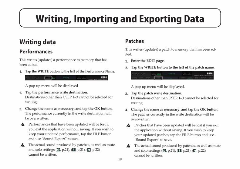
Writing dataPerformancesThis writes (updates) a performance to memory that has been edited.
1. Tap the WRITE button to the left of the Performance Name.
A pop-up menu will be displayed
2. Tap the performance write destination.Destinations other than USER 1–3 cannot be selected for writing.
3. Change the name as necessary, and tap the OK button.The performance currently in the write destination will be overwritten. Performances that have been updated will be lost if
you exit the application without saving. If you wish to keep your updated performance, tap the FILE button and use “Sound Export” to save.
The actual sound produced by patches, as well as mute and solo settings ( , p.21), ( , p.21), ( , p.22) cannot be written.
PatchesThis writes (updates) a patch to memory that has been ed-ited.
1. Enter the EDIT page.
2. Tap the WRITE button to the left of the patch name.
A pop-up menu will be displayed.
3. Tap the patch write destination.Destinations other than USER 1–3 cannot be selected for writing.
4. Change the name as necessary, and tap the OK button.The patches currently in the write destination will be overwritten. Patches that have been updated will be lost if you exit
the application without saving. If you wish to keep your updated patches, tap the FILE button and use “Sound Export” to save.
The actual sound produced by patches, as well as mute and solo settings ( , p.21), ( , p.21), ( , p.22) cannot be written.
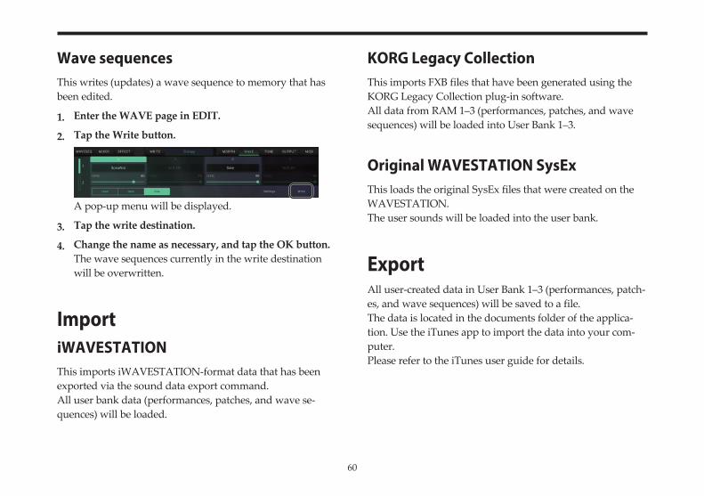
60
Wave sequencesThis writes (updates) a wave sequence to memory that has been edited.
1. Enter the WAVE page in EDIT.
2. Tap the Write button.
A pop-up menu will be displayed.
3. Tap the write destination.
4. Change the name as necessary, and tap the OK button.The wave sequences currently in the write destination will be overwritten.
ImportiWAVESTATIONThis imports iWAVESTATION-format data that has been exported via the sound data export command.All user bank data (performances, patches, and wave se-quences) will be loaded.
KORG Legacy CollectionThis imports FXB files that have been generated using the KORG Legacy Collection plug-in software.All data from RAM 1–3 (performances, patches, and wave sequences) will be loaded into User Bank 1–3.
Original WAVESTATION SysExThis loads the original SysEx files that were created on the WAVESTATION.The user sounds will be loaded into the user bank.
ExportAll user-created data in User Bank 1–3 (performances, patch-es, and wave sequences) will be saved to a file.The data is located in the documents folder of the applica-tion. Use the iTunes app to import the data into your com-puter.Please refer to the iTunes user guide for details.
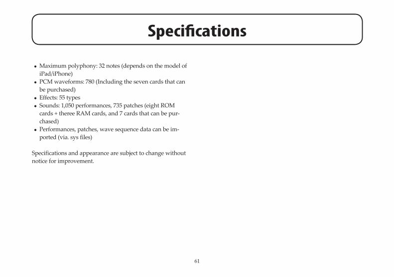
61
Specifications
• Maximum polyphony: 32 notes (depends on the model of iPad/iPhone)
• PCM waveforms: 780 (Including the seven cards that can be purchased)
• Effects: 55 types• Sounds: 1,050 performances, 735 patches (eight ROM
cards + theree RAM cards, and 7 cards that can be pur-chased)
• Performances, patches, wave sequence data can be im-ported (via. sys files)
Specifications and appearance are subject to change without notice for improvement.
62
Support and service
If you have questions about the product, please contact the Korg distributor for the country in which you purchased it.
Information to provide when contacting usIn order for us to help you, we’ll need the following informa-tion since product support cannot be provided without it• Your name• The name and version of the product (How to check the
version)• The name of the device that you’re using• The version of the operating system• Your question (provide as much detail as possible)
Before you contact us• Before you contact us, check whether this manual or
KORG app Help Center has an answer for your question.• Please be aware that we cannot answer questions about
products that are not made by Korg, such as basic opera-tion of your hardware device, or general questions about creating songs or sounds.