i RI j8 968 PLEASE DO NOT REMOVE FROM LIBRARY Bureau of Mines Report of Investigations/19 85 Laboratory Tests of Spalling, Breaking, and Abrasion of Wear-Resist ant Alloys Used in Min ing and M ineral Processing By R. Blickensderfer and J. H. Tylczak UNITED STATES DEPARTM ENT OF THE INTERIOR M,NES 75TH
Transcript
iRIj8968 PLEASE DO NOT REMOVE FROM LIBRARY
Bureau of Mines Report of Investigations/198 5
Laboratory Tests of Spalling, Breaking, and Abrasion of Wear-Resistant Alloys Used in Mining and M ineral Processing
By R. Blickensderfer and J. H. Tylczak
UNITED STATES DEPARTM ENT OF THE INTERIOR i~~1 O~,~~
M,NES 75TH A~
Report of Investigat ions 8968
Laboratory Tests of Spalling, Breaking, and Abrasion of W ear-Resistant Alloys Used in Mining and Mineral Processing
By R. Blickensderfer and J. H. Tylczak
UNITED STATES DEPARTMENT OF THE INTERIOR
Donald Paul Hodel. Secretary
BUREAU OF MINES
Robert C. Horton, Director
Library of Congress Catal oging in Publ icat ion Data:
Blicken s derfer , Robert
La boratOry tes ts of spallin g, breaking , and abrasi on o f wea r-resistant a ll oys used in min ing a nd min e ra l process ing.
( Report o f in ves ti gations; 89G8)
Bibl iography : p. 17.
Supt. of Docs . no .: [ 28 . 23 :8968 .
I. All oys-[mpac t tes ting. 2 • . Mining ma c hine ry . 3. Milling mac hine ry . I. TyIcza k, J. H. (J oseph H. ). [I. Title. ][1. Se ri es : RePOrt of in ve s t iga t ions (Un ite d States . Burea u o f Mines) ; 8968 .
Typical three-ball casting •••.•••••••.••••••.••••.•••••••.••••.•••••.•••••• Repeated-impact wear testing machine •.••••••••••••••••.••••.••.••••••••••.• Pin-on-drum abrasive-wear testing machine ••••••••..••••••••••••.•••••.••••• Four types of failures from repetitive ball-on-ball impacts •••••••.•..••••. Flaking of surface of steel ball subjected to repeated impacts ••••••••••••• Impac t surf ace of a Cr-Mo whi te cas t i ron ball •.••••••.•.••.•..••••••.••••• Development of spalling microcrack beneath a surface subjected to repeated
Analyzed composition of specimens ••••••••••••••••••••••••••••.•••••••••.•.. Heat treatment and microstructure of specimens •.••••.•••••••...•.•••••••.•. Results of repeated-impact and abrasive-wear tests •.••••••••••••••••••.•..•
4 5
10
UNIT OF MEASURE ABBREVIATIONS USED IN THIS REPORT
°c degree Celsius kg kilogram
of degree Fahrenheit m meter
cm centimeter m/min meter per minute
cm2 square centimeter !lm micrometer
cm 3 cubic centimeter mg milligram
g gram mg/r milligram per revolution
g/cm3 gram per cubic centimeter mm millimeter
gal gallon mm 3 /m cubic millimeter per meter
h hour min minute
HB Brinell hardness rpm revolution per minute
in inch wt pct weight percent
J joule
LABORATORY TESTS OF SPALLlNG, BREAKING, AND ABRASION OF WEAR-RESISTANT ALLOYS USED IN MINING
AND MINERAL PROCESSING
By Ro Blickensderfer 1 and J o H. Tylczak 2
ABSTRACT
Laboratory wear testing was conducted by the Bureau of Mines on a variety of typical wear-resistant alloys used in mining and mineralprocessing equipment to establish their relative spalling and abrasion resistance. Test specimens in the form of 75-mm-diam balls were subjected to repeated impacts until they broke, spalled excessively, or received several hundred thousand impacts. Pin specimens removed from the balls were evaluated for high-load abrasive wear. The alloys included commercial forged steels, cast steels, manganese steels, and four types of white cast iron, with a range of heat treatments. The effects of hardness and microstructure on impact wear and abrasive wear are discussed- The data should help mine operators select the compositions and heat treatments that best suit service conditions.
lSupervisory metallurgist. 2Metallurgist. Albany Research Center, Bureau of Mines, Albany, OR.
2
INTRODUCTION
When mining equipment is excavating, crushing, and grinding ore, it is subjected to a wide variety of wear conditions. One of the most insidious and severe wear conditions is a combination of repeated impacts and abrasion, such as occurs in hammer mills, ball mills, excavator teeth, and pulverizers. Materials that are resistant to repeated impacts generally are not very resistant to abrasion and vice versa. Lack of information on the resistance to repeated impacts has hampered the ability to match alloys to the particular impact-abrasion condition.
Although several reproducible abrasivewear tests have been devised, repeatedimpact tests that give reproducible results in a reasonable length of time generally are lacking. Recently, the Bureau of Mines devised a repeated-impact test that was relatively fast and gave reasonably reproducible results (1).3 Consequently, it became possible to-determine relations between repeated-impact wear and abrasive wear of alloys.
A number of investigators have studied wear of materials under simultaneous impact and abrasion conditions found in ball mills. Ellis (~) conducted early tests in I-gal jar ball mills. The impact forces in such a small-diameter mill were probably insignificant. Norman and Loeb (3) conducted studies on 75-mm-diam balls Tn a I-m-diam laboratory mill and studied wear of marked balls in commercial mills. Spalling and broken test
balls were found in the commercial mill, but the number of impacts to cause failure could not be determined. Paul and Hamel (4) evaluated materials by using a rotating-impeller test specimen inside a counterrotating drum, thus producing impact and abrasion between the impeller and the ore. Eleven alloys were compared qualitatively. Pearlitic steel was least effective, white cast irons were very wear resistant, and a lean-Mn steel containing C, Cr, and Mo was the most wear resistant. Dixon (5) devised and used one of the early b~ll-drop testing machines to produce known numbers of repeated impacts in the absence of abrasion. Test balls, 38 mm in diam, \-lere dropped 6.4 m onto an anvil. In studies of the effect of heat treatment on a NiCr white cast iron, the number of impacts to cause fracture ranged from a few hundred to 7,200, depending upon the type of heat treatment. Studman and Field (6) developed an apparatus that produced repeated low-velocity impact damage by a 3-mm-diam tungsten carbide (WC) sphere on the surface of a test specimen. On a hardened carbon steel test specimen, 50 impacts produced radial cracks outside the contact area and flakes within the contact region.
The purpose of this report is to show relationships between repeated impact wear and abrasive wear, as well as other properties, on a variety of typical wearresistant alloys.
EXPERIMENTAL METHODS
ALLOYS
Twenty-two compositions, representing a wide range of wear-resistant materials, were selected, and as many as 11 different heat treatments were given to each composition. In this report, a given
3Underlined numbers in parentheses refer to items in the list of references at the end of this report.
composition with a particular heat treatment is designated as an aZZ oy. Only a few typical heat treatments were selected for inclusion here, giving a total of 34 alloys. Each alloy includes at least 3, and as many as 14, duplicate balls for repeated-impact testing. The alloy compositions presented in table 1 are
grouped into seven categories. The heat treatments are included in table 2. The seven categories are:
1. Forged steel, alloys 1 5. Includes three types of commercial steel grinding balls, and two chromium steel alloys. The 3 commercial grinding ball alloys are representative of 12 different types of commercial balls evaluated. More detailed results on the commercial balls are given in a previous publication (7) • -2. Cast steel, alloys 6-10. Includes
medium- and high-carbon steels with a range of chromium content.
3. Mn steel, alloys 11-19. Includes four compositions of lean-Mn steel and Hadfield steel, both forged and cast, and several heat treatments,
4. Ni-Cr white cast iron, alloys 20-23. Includes a low-Cr-Ni alloy of the Ni-Hard 1 type and 9Cr-Ni alloys of the Ni-Hard 4 type with three heat treatments.
5. Cr-Mo white cast iron, alloys 24-27. Two compositions. Three alloys of the same composition were selected as representative of a more extensive series of 11 heat treatments (8).
6. Cr white cast iron, alloys 28-31. Two compositions. Three alloys of the same composition were selected as typical of a more extensive series of 11 heat treatments.
7. Sulfur white cast iron, alloys 32-34. Two compositions, one with two heat treatments, were selected from a more extensive test series. The sulfur white irons, containing FeMnS hard particles, are not commonly used in mining and processing applications but are believed to have potential for those applications ( 9) •
All test specimens consisted of 75-mm-diam balls. Most were cast, either by a commercial foundry or by our own laboratory; others were forged. Laboratory melts were air-induction melted in 20- to 40-kg charges. The commercial steel balls were purchased in the forged condition. Two of the Mn steel alloys were hot-forged in closed dies in our laboratory.
3
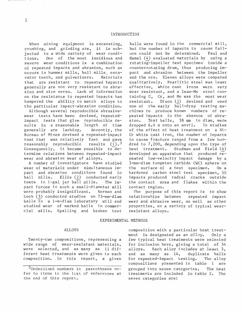
The cast balls were made in groups of three. The 75-mm-diam balls were connected by generously sized gates, 3 cm by 3 cm, to a central pouring basin or riser 10 cm in diameter. The large gates and riser assured that liquid metal was available to the balls during solidification, thereby preventing shrinkage cavities. The castings were allowed to cool for several hours before shakeout. A typical casting is shown in figure 1. The balls were cut off at the gates with a slow-speed band saw fitted with a tungsten carbide-edged blade. This sawing method was found to prevent heat checking during cutting.
Many of the balls were heat treated by the producer; others were heat treated in our laboratory. The heat treatments chosen (table 2) were similar to the commercial heat treatment normally used for the given alloy. Several of the compositions, a lean-Mn steel and four of the alloyed white cast irons, were given a series of heat treatments in order to study the effect of heat treatment and microstructure on spalling. Specimens were heated ~n a neutral atmosphere to prevent decarburization.
6 -- 10 --FIGURE 1. - Typical three-ball casting. The
balls are nominally 75 mm in diameter.
4
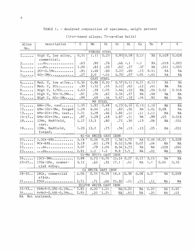
TABLE 1. - Analyzed composition of specimens, weight percent
(Iron-based alloys; 75-cm-diam balls)
Alloy No.
1 ••••••
2 •••.•• 3 •••••• 4 ••.••• 5 ••••••
- .-. ~
6 •••••• 7 •••••• 8 •.• c c •
9 •••••• 10 •••••
11 ••••• 12 .•••• 13 ••.•• 14-17 •• 18 ••.••
19 •••••
20 ••••• 21 ••••• 22 •.••• 23 .••••
24 ••.•• 25-27 ••
28-:fo ••
31 ••••.
32-33 •• 34 ••.••
Description
High C, low alloy, commercial.
••• do •••.••.••••.•• ••• do ••••••••• • •••• 2Cr-0.5Mo •••••••..• 4Cr-2Mn .••••••••• • •
Med. C, low alloy •• Med. C, 2Cr •••.•••• High C, 1. 5Cr •••.•• High C, 3Cr-0. 5Mo •• High C, 6Cr-1Mo ••••
15Cr-3Mo •••••••••••••• Austenitize at 980 0 C for 8 h, fan cool to 540 0 C, AC.
17Cr-1Mo, commercial As cast ••••••••••••••••••••• alloy.
••• do ••••••••••••••••• Austenitize at 1,010 0 C for 4 h, AC.
••• do ••••••••••••••••• Austenitize at 1,0100 C for 4 h, AC, temper at 540 0 C for 12 h.
Cr WHITE CAST IRON 28 ••• 18Cr, commercial alloy As cast •••••••••••••••••••••
29 •••••• do ••••••••••••••••• Temper at 540 0 c ........... .
30 •••••• do ••••••••••••••••• Austenitize, commercially proprietary temperature, t-emper at 510 0 C.
31 ••• 25Cr •••••••••••••••••• Austenitize at 9800 C for 8 h, fan cool to 540 0 C, AC.
SULFUR WHITE CAST IRON 32 ••• FeMnS-0.2Ni-0.1Mo ••••• Heat in N2 at 910 0 C for 2
h, FC to 845 0 C, hold 1 h, AC; reheat to 565 0 C for 2 h, FC to 345 0 C, AC.
33 •••••• do ••••••••••••••••• Heat in N2 at 565 0 C for 2 h, FC to 345 0 C, AC.
34 ••• FeMnS-0.4Ni-0.2Mo ••••• Heat in N2 at 910 0 C for 2 h, FC to 845 0 C hold 1 h, AC; reheat to 565 0 C for 2 h, FC to 345 0 C, AC.
Continuous martensite with retained austenite, about 30 pet acicular carbides.
Dendritic austenite. Interdendritic Fe-Cr acicular carbides with secondary austenite •
Dendrites, partially transformed to martensite. Interdendritic M7C3 needles •
Dendrites of tempered martensite. Interdendritic M7C3 -
Almost continuous dendrites of austenite. Interdendritic and Fe-Cr carbides.
Austenitic dendrites, edges transformed to martensite . Interdendritic M7C3 needles.
Dendrites of tempered martensite. M7C3 particles (former needles) interdendritic.
Continuous tempered martensite with about 30 pet acicular and globular carbides.
Tempered martensite and ferrite. About 35 pet coarse carbides. Scattered FeS-MnS particles.
Coarse pearlite and ferrite. About 45 pet almost continuous network of coarse carbide. Scattered FeSMnS particles.
Similar to alloy 32, slightly less coarse.
AC Air cool. FC Furnace cool. OQ Oil quench. WQ Water quench.
ANALYSES
Specimens for chemical analysis were taken from the gate of the casting. Analytical methods included optical emission spectroscopy, for low alloys; X- ray fluorescence spectroscopy, for white cast irons; gas ignition with infrared detection, for carbon and sulfur; and wet chemistry, for phosphorus and for calibrating the spectroscopic methods. The analyses are presented in table 1.
Standard metallographic procedures were used to mount, grind, polish, and etch the specimens.
Hardness measurements were made on one or more small flat spots ground on the balls. A Brinell hardness tester with a tungsten carbide ball and a 3,OOO-kg load was used.
REPEATED-IMPACT WEAR TEST
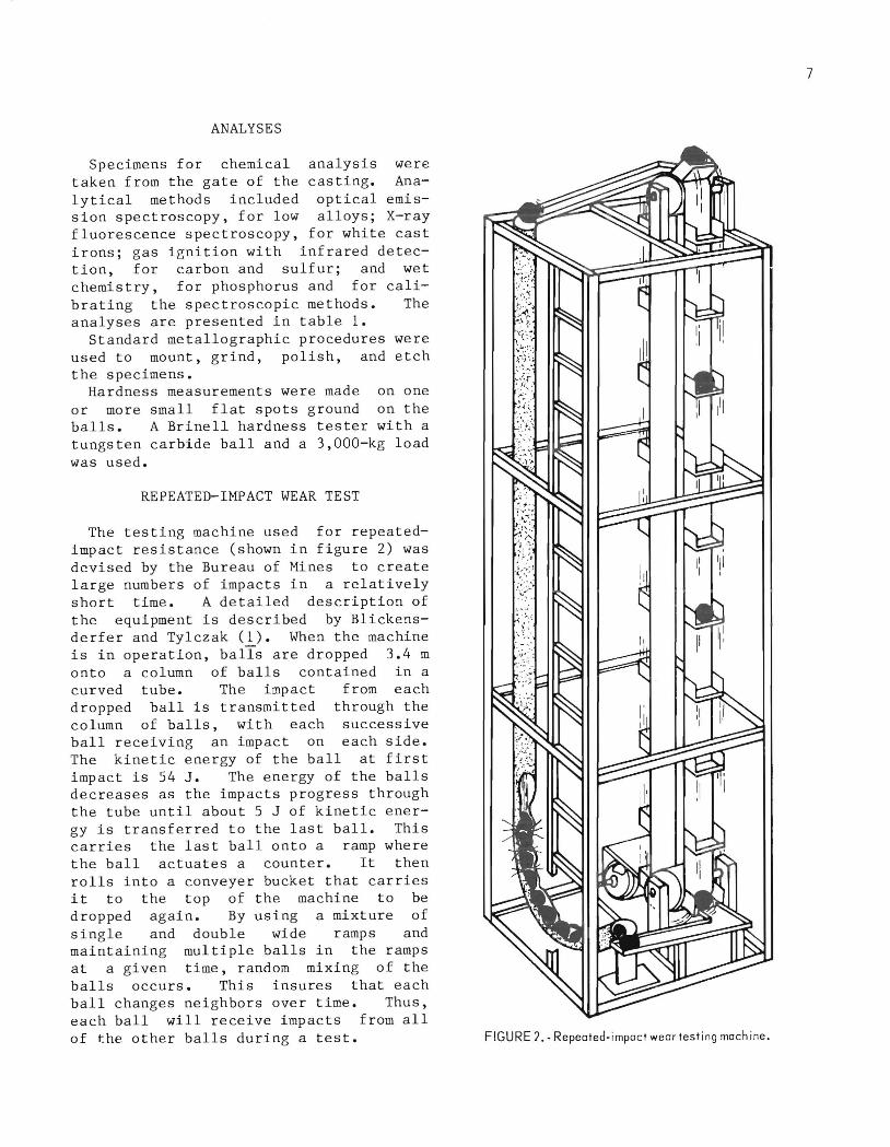
The testing machine used for repeatedimpact resistance (shown in figure 2) was devised by the Bureau of Mines to create large numbers of impacts in a relatively short time. A detailed description of the equipment is described by Blickensderfer and Tylczak (1). When the machine is in operation, balls are dropped 3.4 m onto a column of balls contained in a curved tube. The impact from each dropped ball is transmitted through the column of balls, with each successive ball receiving an impact on each side. The kinetic energy of the ball at first impact is 54 J. The energy of the balls decreases as the impacts progress through the tube until about 5 J of kinetic energy is transferred to the last ball. This carries the last ball onto a ramp where the ball actuates a counter. It then rolls into a conveyer bucket that carries it to the top of the machine to be dropped again. By using a mixture of single and double wide ramps and maintaining multiple balls in the ramps at a given time, random mixing of the balls occurs. This insures that each ball changes neighbors over time. Thus, each ball will receive impacts from all of t.he other balls during a test.
Since many different specimens were run simultaneously, each ball was identified by grinding a distinctive pattern of two or three small flats on its surface.
To start a test, 22 balls are loaded into the machine, 18 balls in the tube and 4 in the ramps and conveyer buckets. During operation, the machine drops about 22 balls per minute. For each ball dropped, 36 impacts are created--two on each ball in the tube. This gives a rate of about 45,000 total impacts per hour in the system. The machine was operated until a ball spalled excessively, or broke and blocked a ramp, or until each ball had been subjected to about 15,000 additional impacts. All balls were then removed and weighed. Balls that either
broke or spalled more than 100 g did not roll down the ramps properly and were replaced. The total number of impacts on each ball was calculated from the ball count. Balls were replaced by either another test bailor a hardened steel filler ball.
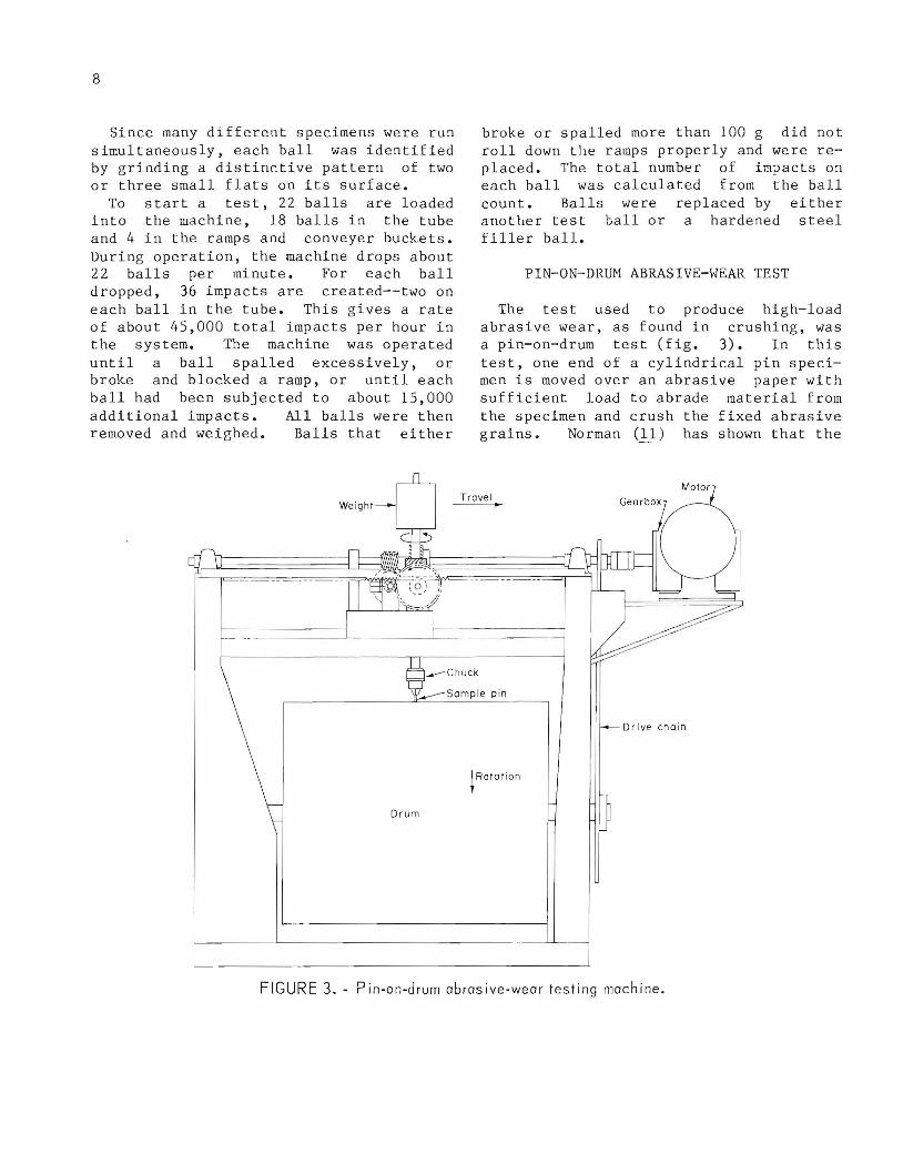
PIN- ON- DRUM ABRASIVE-WEAR TEST
The test used to produce high-load abrasive wear, as found in crushing, was a pin-on-drum test (fig. 3). In this test, one end of a cylindrical pin specimen is moved over an abrasive paper with sufficient load to abrade material from the specimen and crush the fixed abrasive grains. Norman (ll) has shown that the
pin test simulates the wear that occurs during crushing and grinding of ore in which the ore (the abrasive) is crushed.
The pin-on-drum abrasive-wear testing machines represent an improved variation of the more commonly used pin-on-disk machines that others have used to produce high-load abrasive wear. Unlike the pinon-disk machines , the pin-on-drum machines provide constant surface speed and rotate the specimen. Our apparatus was patterned after the pin-on-table machine of Climax Molybdenum Co. (~) and the pin-on-drum machine of the search Laboratories (Q),
Melbourne ReAll three ma-
chines can use the same type abrasive, path length, load, and speed and the pin is rotated.
The pin-on-drum testing equipment consists of a head that rotates the pin test specimen while traversing the length of a rotating cylinder that is covered with abrasive paper. The head has three functions: It loads the specimen, it translates the specimen along the cylinder so that only fresh abrasive is encountered, and it rotates the test specimen to produce wear scars in all directions. The steel cylinder is 0.509 m in diam and 61 cm long. A garnet abrasive cloth, made from 105-~m garnets, was obtained in rolls 61 cm wide from a commercial source, cut to length, and glued to the cylinder. During operation, the drum turns at 1.7 rpm to give a surface speed of 2.7 m/min, while the pin specimen rotates at 17 rpm. Through gearing, a single motor drives the entire machine. The drive automatically stops after completing a preset number of revolutions.
Specimens were cleaned ultrasonically, rinsed in alcohol, and hot air dried before each weighing. A new test specimen was worn-in for approximately four drum revolutions before beginning the test runs. The test of a material requires two runs of the machine, one on the test specimen and one on a standard specimen. The test specimen run required about six drum revolutions for the soft steels and 12 or more revolutions for the hard white irons. After the test specimen run was completed , a standard specimen of ASTM
9
A514 type B wlth hardness of 269 HB was subjected to the same number of drum revolutionsn The wear track of the standard specimen was between the tracks left by the test specimen.
The wear of the standard specimen was used to correct for variations in the abrasiveness of the abrasive cloth. The mass loss of the test specimen rected and converted to volume unit path length using the formula:
was corloss per
following
where
and
corrected wear volume of the test specimen per unit path, mm 3/m,
Wx measured mass loss of the test specimen for X number of revolutions,
Sx measured mass loss of the standard specimen for the same X revolutions in the same mass units as W)"
S long-term average mass loss per drum revolution, mg/r,
p test specimen density, g/cm 3 •
The constant 1.6 is the circumference of the drum in meters.
Test specimens 2 to 3 cm long were removed from along a radius of a ball by electrodischarge machining. The cylindrical surface was finish-ground in a lathe to a diameter of 6.35 ±0.02 mm.
The impact test seven categories average of three i3.lloy and heat
RESULTS
results for each of the of alloys represent an or more balls of each
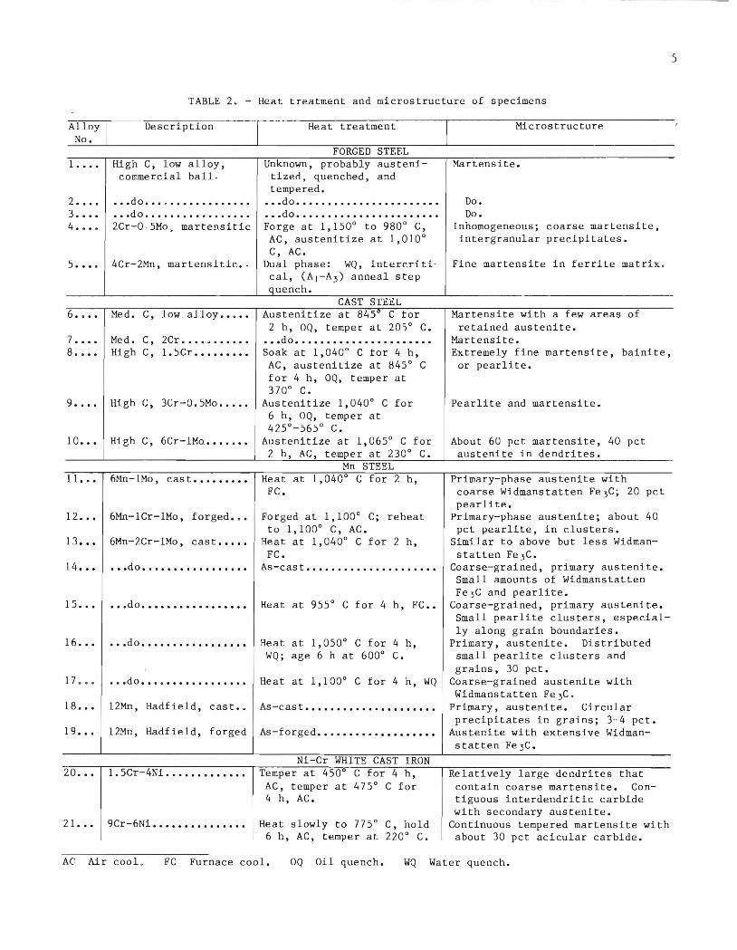
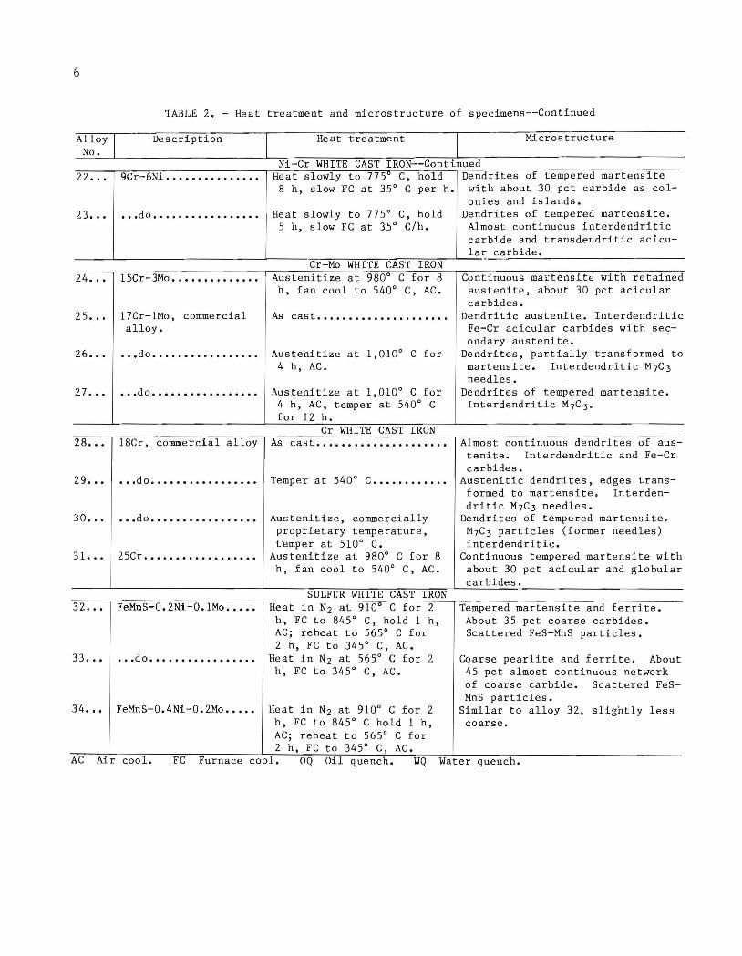
treatment. The heat treatments and microstructure data were summarized earlier in table 2. The hardness and results of the repeated-impact tests and abrasive-wear tests are presented in table 3.
10
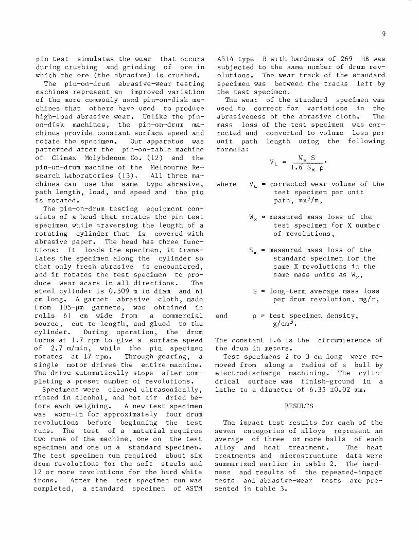
TABLE 3. - Results of repeated-impact and abrasive-wear tests
Repeated-impact wear Alloy Hardness, Densit y , Average number Rate, Abrasive pin
No. HB g/cm3 Failure mode impacts to mg/impact wear, mm 3/m break, 1000' s
SULFUR WHITE CAST IRON Breaking •••••••• • •• do •••.•.••••• • •• do •.•.•••.•..
30 13 20
0.041 .031
ND ND
.025
0.050 .021 .078
5. 1 .010
28 1.1
ND .37 .69 .036 .042 .039 .011
2.4 .72 .16
3.8
16
•
7 11 2.7
.86
J 8.6 1.9
.23 1.4
1 ND ND ND
ND Not determined--insignificant weight loss at time of breaking. lBreaking was associated with casting flaws. 21 or 2 balls broke; all spalled. 3Casting flaws contributed to spalling.
1.101 .634 .513 .450 .886
1.129 .971 .743 .572 .423
""---0.595
.460
.502
.452
.540
.710
.547 NA
.748
0.397 .418 .423 .444
] 0.251 .273 .240 .565 -------
0.267 .474 .480 .577
0.837 .653 .742
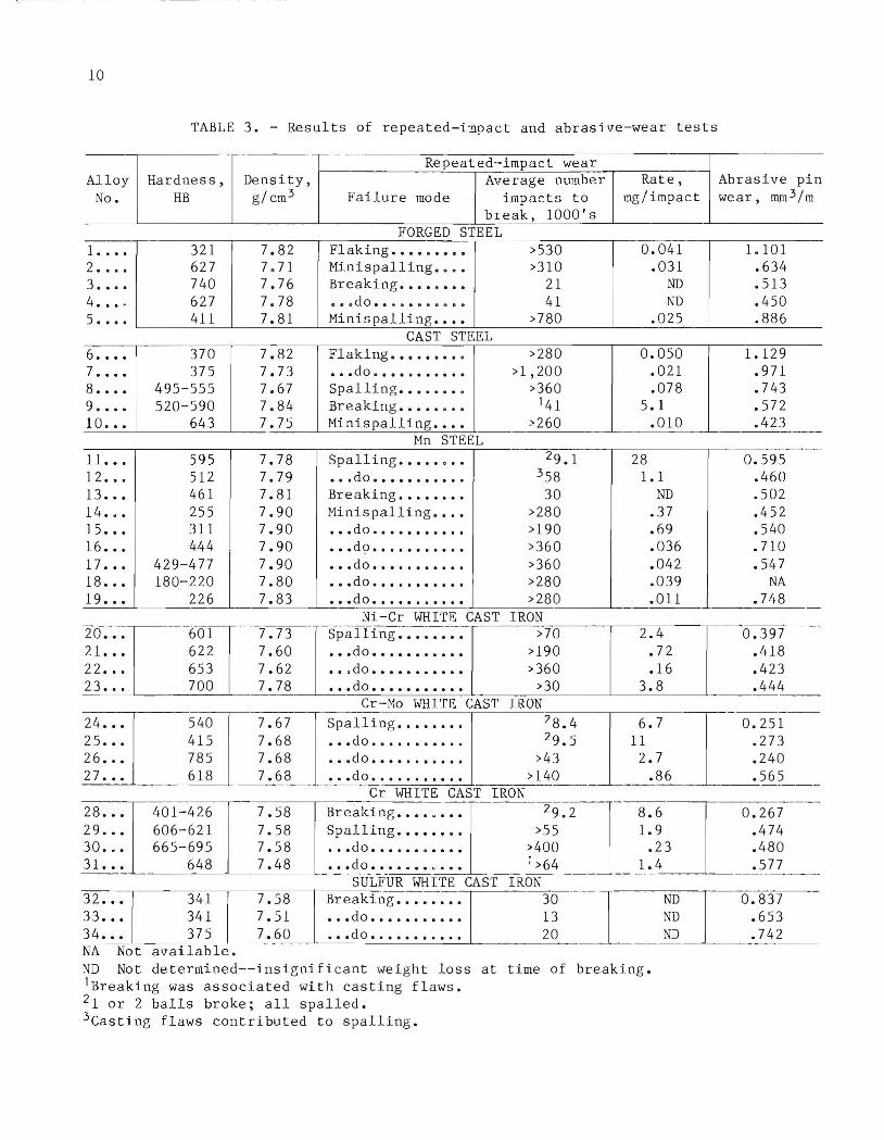
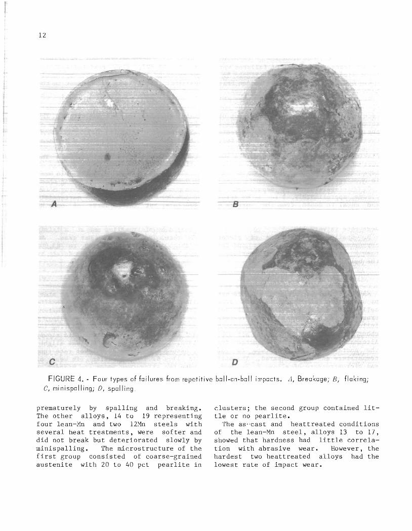
F~om OUI previous research on repeatedimpact tests, four types of failures were identified, as illustrated in figure 4:
A. Breakage. - Major and sudden fra~ ture of the ball, usually into halves.
B. Flaking. - Separation of ve~y thin pieces, 1 to 3 rom across, from the surface of the ball. Flaking is not observed in commercial ball mills because the abrasive-wear rate is much greater than the flake formation rate. Balls with sufficient ductility to sustain flaking usually began to deform into some sort of polyhedron after 200,000 or more impacts. Worn polyhedral balls are found in commercial ball mills.
C. Minispalling. Separation of pieces, approximately 1 to 3 mm across and equal in depth, from the surface of the ball. Minispalling is not observed in field applications unless the abrasive wear rate is very low.
D. Spalling. - Separation of pieces, approximately 1 to 3 cm across and less than 1 cm in depth, from the surface of t he ball.
Forged Steel
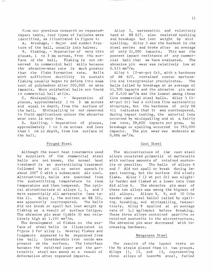
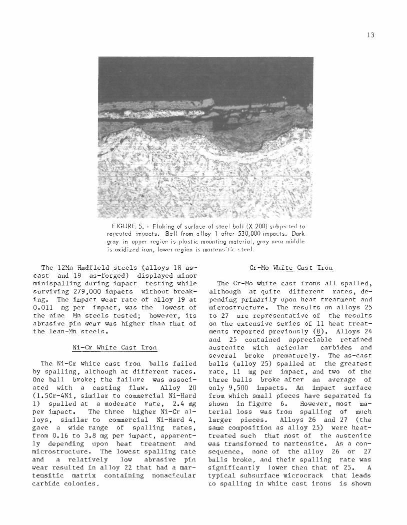
Although the exact heat treatments used by suppliers of the commercial steel balls are not known, the normal heat treatment is an austenitizing treatment followed by an oil or water quench to about 200 0 C with a subsequent air cool. Alternatively, balls are quenched from the austenitizing temperature to room temperature and then tempered. The optical microstructure of alloys 1, 2, and 3 were essentially all martensite (see table 2). Alloy 1, the softest at HB 321, was apparently overtempered. The balls did not break or spall but lost weight by flaking as a result of surface fatigue. The abrasive pin wear (table 3) was relatively high at 1.101 mm 3 /m.
The development of flakes on the surface of steel balls is illustrated in figure 5 for alloy 1. Several flakes and fragments appeared to be separated from the ball. Considerable iron oxide was present on the surface. The interface between the oxidized layer and the martensitic steel was wavey as a result of deformation after repeated impacts.
11
Alloy 2, martensitic and relatively hard at HB 627, also resisted spalling and breakage but lost weight by mlnlspalling. Alloy 3 was the hardest in the steel series and broke after an average of only 21,000 impacts. This was the poorest impact resistance of any commercial ball that we have evaluated. The abrasive pin wear was relatively low at 0.513 mm 3 / m.
Alloy 4 (2-wt-pct Cr), with a hardness of HB 627, contained coarse martens-ite and intergranular precipitates. The balls failed by breakage at an average of 41,300 impacts and the abrasive pin wear of 0.450 mm 3 /m was the lowest among these five commercial steel balls. Alloy 5 (4-wt-pct Cr) had a uniform fine martensitic structure, but the hardness of only HB 411 indicates that it was overtempered. During impact testing, the material loss occurred by minispalling and at a fairly low rate, 39,600 impacts per gram. No breakage or spalling occurred to 783,000 impacts. The pin wear was moderate at 0.886 mm 3 /m.
Cast Steel
The microstructure of the cast steel alloys consisted primarily of martensite with various amounts of retained austenite or pearlite. The balls of alloys 6 and 7 did not spall or break during impact testing, but the surface did slowly flake. Alloy 7 (2 wt pct Cr) was slightly harder and flaked at a lower rate than did alloy 6. The abrasive pin wear of these two alloys was among the highest of all alloys. Alloys 8, 9, and 10 (the harder cast steel balls) failed by spalling, breaking, and minispalling, respectively. Alloy 9 spalled at an average rate of 5.1 mg/impact before breaking. These three alloys contained pearlite or retained austenite in the microstructure. The abrasive pin wear decreased with increasing hardness.
The the Mn Alloys three
Manganese Steel
results of the impact tests on steels placed them in two groups.
11, 12, and 13, representing alloys of lean-Mn steel, failed
r
1-
12
- 8
FIGURE 4. Four types of failures from repetitive bail-an-bail impacts. A, Breakage; B, flaking;
C, minispalling; 0, spoiling .
prematurely by spalling and breaking. The other alloys, 14 to 19 representing four lean-Mn and two 12Mn steels with several heat treatments, were softer and did not break but deteriorated slowly by minispalling. The microstructure of the first group consisted of coarse-grained austenite with 20 to 40 pet pearlite in
clusters; the second group contained little or no pearlite.
The as· ·cast and heattreated conditions of the lean-Mn steel, alloys 13 to 17, showed that hardness had little correlation with abrasive wear. However, the hardest two heat treated alloys had the lowest rate of impact wear.
13
FIGURE 5. - Flaking of surface of steel ball (X 200) subjected to repeated impacts. Ball from alloy 1 after 530,000 impacts. Dark
gray in upper region is plastic mounting material, gray near middle
is oxidized iron, lower region is martensitic steel.
The 12Mn Hadfield steels (alloys 18 ascast and 19 as-forged) displayed minor minispalling during impact testing while surviving 279,000 impacts without breaking. The impact wear rate of alloy 19 at 0.011 mg per impact, was the lowest of the nine Mn steels tested; however, its abrasive pin wear was higher than that of the lean-Mn steels.
Ni-Cr White Cast Iron
The Ni-Cr white cast iron balls failed by spalling, although at different rates. One ball broke; the failure was associated with a casting flaw. Alloy 20 (1.5Cr-4Ni, similar to commercial Ni-Hard 1) spalled at a moderate rate, 2.4 mg per impact. The three higher Ni-Cr alloys, similar to commercial Ni-Hard 4, gave a wide range of spalling rates, from 0.16 to 3.8 mg per impact, apparently depending upon heat treatment and microstructure. The lowest spalling rate and a relatively low abrasive pin wear resulted in alloy 22 that had a martensitic matrix containing nonac:i_cular carbide colonies.
Cr-Mo White Cast Iron
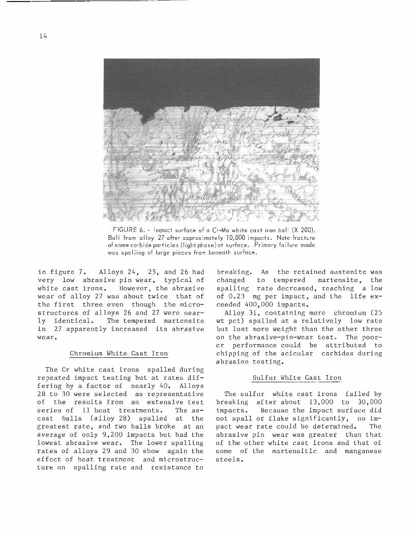
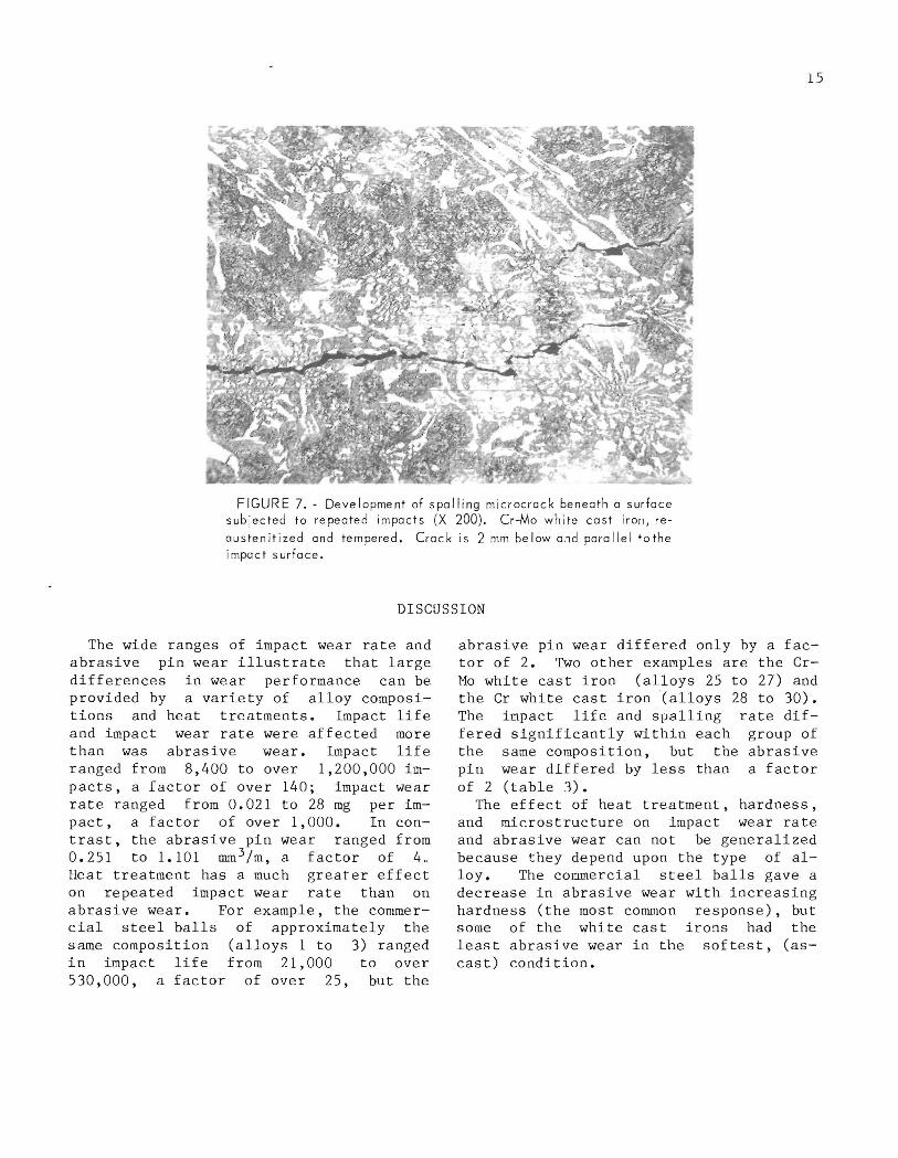
The Cr-Mo white cast irons all spalled, although at quite different rates, depending primarily upon heat treatment and microstructure. The results on alloys 25 to 27 are representative of the results on the extensive series of 11 heat treatments reported previously (~). Alloys 24 and 25 contained appreciable retained austenite with acicular carbides and several broke prematurely. The as-cast balls (alloy 25) spalled at the greatest rate, 11 mg per impact, and two of the three balls broke after an average of only 9,500 impacts . An impact surface from which small pieces have separated is shown in figure 6. However, most material loss was from spalling of much larger pieces. Alloys 26 and 27 (the same composition as alloy 25) were heattreated such that most of the austenite was transformed to martensite. As a consequence, none of the alloy 26 or 27 balls broke, and their spalling rate was significantly lower th2n that of 25. A typical subsurface microcrack that leads to spalling in white cast irons is shown
14
FIGURE 6 . - Impact surface of a Cr-Mo white cast iron ball (X 200). Ball from alloy 27 after approximately 10,000 impacts. Note fracture of some carbide particles ( light phase)at surface . Primary failure mode was spalling of large pieces from beneath surface.
in figure 7. Alloys 24, 25, and 26 had very low abrasive pin wear, typical of white cast irons. However, the abrasive wear of alloy 27 was about twice that of the first three even though the microstructures of alloys 26 and 27 were nearly identical. The tempered martensite in 27 apparently increased its abrasive wear.
Chromium White Cast Iron
The Cr white cast irons spalled during repeated impact testing but at rates differing by a factor of nearly 40. Alloys 28 to 30 were selected as representative of the results from an extensive test series of 11 heat treatments. The ascast balls (alloy 28) spalled at the greatest rate, and two balls broke at an average of only 9,200 impacts but had the lowest abrasive wear. The lower spalling rates of alloys 29 and 30 show again the effect of heat treatment and microstructure on spalling rate and resistance to
breaking. As the retained austenite was changed to tempered martensite, the spalling rate decreased, reaching a low of 0.23 mg per impact, and the life exceeded 400,000 impacts.
Alloy 31, containing more chromium (25
wt pct) spalled at a relatively low rate but lost more weight than the other three on the abrasive-pin-wear test. The poorer performance could be attributed to chipping of the acicular carbides during abrasion testing.
Sulfur White Cast Iron
The sulfur white cast irons failed by breaking after about 13,000 to 30,000 impacts. Because the impact surface did not spall or flake significantly, no impact wear rate could be determined. The abrasive pin wear was greater than that of the other white cast irons and that of some of the martensitic and manganese steels.
15
FIGURE 7.· Development of spalling microcrack beneath a surface subjected to repeated impacts (X 200). Cr-Mo white cast iron, re
austenitized and tempered. Crack is 2 mm below and parallel tothe impact surface.
DISCUSSION
The wide ranges of impact wear rate and abrasive pin wear illustrate that large differences in wear performance can be provided by a variety of alloy compositions and heat treatments. Impact life and impact wear rate were affected more than was abrasive wear. Impact life ranged from 8,400 to over 1,200,000 impacts, a factor of over 140; impact wear rate ranged from 0.021 to 28 mg per impact, a factor of over 1,000. In contrast, the abrasive pin wear ranged from 0.251 to 1.101 mm 3 /m, a factor of 4. Heat treatment has a much greater effect on repeated impact wear rate than on abrasive wear. For example, the commercial steel balls of approximately the same composition (alloys 1 to 3) ranged in impact life from 21,000 to over 530,000, a factor of over 25, but the
abrasive pin wear differed only by a factor of 2. Two other examples are the CrMo white cast iron (alloys 25 to 27) and the Cr white cast iron (alloys 28 to 30). The impact life and spalling rate differed significantly within each group of the same composition, but the abrasive pin wear differed by less than a factor of 2 (table 3).
The effect of heat treatment, hardness, and microstructure on impact wear rate and abrasive wear can not be generalized because they depend upon the type of alloy. The commercial steel balls gave a decrease in abrasive wear with increasing hardness (the most common response), but some of the white cast irons had the least abrasive wear in the softest, (ascast) condition.
16
FORGED STEEL
The three types of commercial balls had decreasing abrasive wear with increasing hardness and carbon content. The microstructure of all three was primarily martensitic. In the chromium steel alloys, the coarse martensite and inhomogeneity probably contributed to the early breaking of alloy 4 and the continuous ferrite explains the excellent resistance to breakage but high abrasive wear of alloy 5.
CAST STEEL
As with the forged steel alloys, the abrasive wear decreased as hardness inc r eased. High hardness up to HB 650 reduces the abrasive wear and does not necessarily lead to breaking. Apparently, the microstructure, rather than hardness, controls the spalling and breaking. Tempered martensite is desirable for long life against breaking, whereas pearlite may contribute to premature breaking o
MANGANESE STEEL
As is already known, the abrasive wear of highly work-hardenable materials, such as copper, nickel, and manganese steel, does not depend upon the initial hardness that was produced by work hardening because these materials work-harden during the wear process. The present results show, in addition, that the abrasive wear of lean-Mn steel does not depend upon the hardness produced by heat treatments. However, the breaking, spalling, and impact wear rate of the lean-Mn steels are affected by heat treatment. A hightemperature solution treatment followed by a quench that suppresses the formation of pearlite seems to provide the best resistance to impact conditions.
All of the lean-Mn steels were more abrasion resistant than was the 12Mn steel, in agreement with the findings of others (lQ-Q)
Ni-Cr WHITE CAST IRON
The hardened alloys have relatively low abrasive wear. Spalling is the main
problem when these alloys are subjected to repeated impacts. The spalling rate can be low if the microstructure consists of almost continuous tempered martensite with scattered carbides; however, a continuous carbide phase or a network of acicular carbides leads to excessive spalling rates.
Cr-Mo WHITE CAST IRON
The abrasive wear of these alloys was the lowest of all, but the spalling rates were among the highest. High spalling rates may be associated with retained austenite and acicular carbides in the microstructure. Dodd (14) has reported that retained austenite leads to spalling of Cr-Mo white cast irons subjected to repeated impacts. The present results indicate that small differences in the amount of transformed and tempered martensite resulting from heat treatment also can affect the spalling rate. Tempering the martensite reduces the spalling wear, but overtempering increases the abrasive wear .
CHROMIUM WHITE CAST IRON
The behavior of these alloys was similar to the preceding set that contained molybdenum. The abrasive wear was not quite as low, on the average. The ascast condition gave the least abrasive wear and the greatest spalling rate. The reaustentized and tempered (about 510 0 C) condition seems to g ive the lowest spalling rate. The condition resulted in no visible austenite in the microstructure.
SULFUR WHITE CAST IRON
The sulfur white cast irons may have potential in repeated impact-abrasive wear service because of their relative low cost. However, both the abrasive wear and breakage must be reduced. The amount of ferrite and pearlite should be reduced to lower the abrasive wear. In addition, reducing the amount of coarse carbides would presumably decrease the breaking.
17
REFERENCES
1. Blickensderfer, R. , and J. H. Tylczak. A Large-Scale Impact Spalling Test. Wear, v. 84, No.3, 1983, pp. 361-373.
2. Ellis, O. W. Wear Tests on Ferrous Alloys. Trans. Am. Soc. Metals, v. 30, 1942, pp. 249-286.
3. Norman, T. E., and E. M. Loeb. Wear Tests on Grinding Balls. Trans. AIME, v. 176, 1948, pp . 490-526 .
4. Paul, G., and H. J. E. Hamel. A Laboratory Method for Predicting Ore MilL Liner Life. South Afr. Mech. Eng., v. 20, No.5, May 1970, pp. 174-179.
5. Dixon, R. H. T. Some Effects of Heat-Treatment Upon the Impact-Fatigue Life of Ni-Hard Grinding Balls. J. Iron and Steel Inst., v. 197, 1961, pp. 40-48.
6. Studman, C. J., and J. E. Field. A Repeated Impact Testing Machine. Wear, v. 41, 1977, pp. 373-381.
7. Blickensderfer, R., J. H. Tylczak, B. W. Madsen, and J. S. Hansen. Evaluating and Improving Materials for Mineral Processing. Paper in Tribology in l1ineral Extraction, War on Wear, Inst. Mech. Eng. (London), 1984, pp. 15-21.
8. Blickensderfer, R., J. H. Tylczak, and J. Dodd. The Effect of Heat Treatment on Spalling of a Cr-Mo White Cast
", u.s. GPO: 1965-505-019120,075
Iron. Paper in Wear of Materials 1983. ASME, New York, 1983, pp. 471-476.
9. Rote, F. B., K. H. Cawler, and M. J. Press. Production and Properties of High Sulfur, Wear-Resistant Cast Iron. Trans. Am. Foundrymen's Soc., v. 88, 1980, pp. 823-834.
10. Miska, K. H. Consider Austenitic Manganese Steels for Impact and Wear Applications. Mater . Eng., v. 86, No .2, 1977, pp. 42-44.
11. Norman, T. E. Climax Finds New Austenitic Alloy Ideal for Ultra-Abrasive Mine ·Mill Applications. Eng. and Min. J., v. 166, No.4, 1965, pp. 86-90.
12. Muscara, J., and M. J. Sinnott. Construction and Evaluation of a Versatile Abrasive Wear Testing Apparatus. Met. Eng. Q., v. 12, No.2, 1972, pp. 21-32.
13. Mutton, P. J. High Stress Abrasion Testing of Wear Resistant Materials. Broken Hill Proprietary Co., Melbourn Res. Lab. (Australia), Lab. Rep. MRL/PM3/ 78/001, Aug. 1978, 49 pp.
14. Dodd, J. Progr ess in the Development and Use of Abrasion-Resistant Alloy Irons and Steels in the l1ining Industry. Trans. SME, v. 270, 1981, pp. 1923-1930.