Submitted to UAV’09 manuscript No. (will be inserted by the editor) Landing and Perching on Vertical Surfaces with Microspines for Small Unmanned Air Vehicles Alexis Lussier Desbiens · Mark Cutkosky Received: March 2nd, 2009 / Accepted: April 20th, 2009 Abstract We present the first results of a system that allows small fixed- wing UAVs to land and cling on surfaces such as brick walls using arrays of microspines that engage asperities on the surface. The requirements of engag- ing and loading the spines lead to an approach in which an open-loop pitch-up motion is triggered by a range sensor as the plane nears the wall. The sub- sequent dynamics result in a period during which the plane stays within an envelope of acceptable orientation and velocity (pitch from 60-105 deg, verti- cal velocity from 0 to -2.7 m/s and up to 3 m/s of horizontal velocity) that permit successful perching. At touchdown, a non-linear suspension absorbs the remaining kinetic energy to minimize peak forces, prevents bouncing and facilitates spine engagement. The total maneuver duration is less than 1 s. We describe the spine suspension and its analysis and present results of typical perching maneuvers (10 landings under autonomous control and 20 under man- ual control). Under calm conditions, the success rate for autonomous perching on building walls is approximately 80 %, the failures being attributed to erro- neous wall detection. We conclude with a discussion of future work to increase the robustness of the approach (e.g. with wind) and allow subsequent take-offs to resume flight. Keywords Perching · Landing · Vertical surfaces · Wall · Microspines · Adhesion · Suspension · Unmanned Air Vehicles · Endurance Stanford University Biomimetic and Dextrous Manipulation Laboratory Center for Design Research 424 Panama Mall, Bldg. 560 Stanford, CA 94305-2232 E-mail: [email protected]
Transcript
Submitted to UAV’09 manuscript No.(will be inserted by the editor)
Landing and Perching on Vertical Surfaces withMicrospines for Small Unmanned Air Vehicles
Alexis Lussier Desbiens · Mark Cutkosky
Received: March 2nd, 2009 / Accepted: April 20th, 2009
Abstract We present the first results of a system that allows small fixed-wing UAVs to land and cling on surfaces such as brick walls using arrays ofmicrospines that engage asperities on the surface. The requirements of engag-ing and loading the spines lead to an approach in which an open-loop pitch-upmotion is triggered by a range sensor as the plane nears the wall. The sub-sequent dynamics result in a period during which the plane stays within anenvelope of acceptable orientation and velocity (pitch from 60-105 deg, verti-cal velocity from 0 to -2.7 m/s and up to 3 m/s of horizontal velocity) thatpermit successful perching. At touchdown, a non-linear suspension absorbsthe remaining kinetic energy to minimize peak forces, prevents bouncing andfacilitates spine engagement. The total maneuver duration is less than 1 s. Wedescribe the spine suspension and its analysis and present results of typicalperching maneuvers (10 landings under autonomous control and 20 under man-ual control). Under calm conditions, the success rate for autonomous perchingon building walls is approximately 80 %, the failures being attributed to erro-neous wall detection. We conclude with a discussion of future work to increasethe robustness of the approach (e.g. with wind) and allow subsequent take-o!sto resume flight.
Stanford UniversityBiomimetic and Dextrous Manipulation LaboratoryCenter for Design Research424 Panama Mall, Bldg. 560Stanford, CA 94305-2232E-mail: [email protected]
310Staff
Proc. UAV'09, Session W2-AM: UAS Landing Challenges 1, Reno, June 8-10 2009.
2
1 Introduction
Miniature unmanned air vehicles are becoming increasingly popular for mil-itary and civilian applications. However, they su!er from a relatively shortflight time, can be di"cult to land safely on the ground, and are vulnerablewhen parked. An attractive alternative is to let them do as many small flyinganimals do: take frequent short flights with periods of perching in between. Inparticular, it is useful for small fixed-wing planes to perch on vertical surfacessuch as cli!s or the walls of buildings. Clinging passively to such surfaces,they consume little power, allowing them to remain for hours or possibly daysas a stable platform for unobtrusive surveillance, inspection or environmentalmonitoring. Vertical surfaces are especially attractive because they are oftenrelatively uncluttered and free from debris. In addition, if the plane perchesunder an overhang, it can ride out a storm in relative safety.
2 Related Work
Although the ability to land and perch on vertical building surfaces is, toour knowledge, new, it draws upon two previous areas of work: (i) fixed-wingplanes that execute dynamic maneuvers for landing and perching (ii) climbingrobots that use micro-spines or directional adhesion for attachment to verticalsurfaces.
2.1 Landing and perching maneuvers
In prior work, perching has been studied mostly from the aerodynamics andcontrol point of view. For example, in one approach, researchers [6] have usedmotion capture cameras (119Hz, sub-millimetre accuracy) to control an RCplane with an o!-board controller for various indoor maneuvers such as flyingin a room and using controlled hovering to land on a specially designed dockingstation. A similar system was used in [5] to create an accurate high-dimensionalmodel of a glider during high angle-of-attack (AOA) maneuvers. This allowsthe plane to perform aggressive pitching maneuvers required to decelerate it toalmost zero velocity before perching on a pole. Due to the challenge imposedby the very small target and the limited actuation control, the entire procedurewas successful 20% of the time. In later work it was shown [14] that the gliderbecomes less controllable as its airspeed drops just before perching, even if acontrollability is improved with a fixed propeller or thrust vectoring.
In other work, autonomous hovering has been demonstrated with fixed-wing aircraft [8,9,7]. The controller is based on the PIC16F87 and uses aMicrostrain 3DM-GX1 inertial measuring unit (30 grams, 100 Hz update rate)to measure spatial orientation. The plane uses rudder and elevator to controlpitch and yaw and has small propellers on the wing tips to control roll.
Still other work has focused on performing perching maneuvers using amorphing airplane [16,17,18]. Simulations show that pitching up the body
3
while keeping wing and tail horizontal allows the plane to maintain controland create lift during the entire maneuver. This approach creates a shorterperching trajectory than one would require with a fixed-wing airplane althoughit adds some mechanical complexity.
Extensive biological research has been devoted both to flying and to groundlocomotion. However, much less has focused on the physics of transitions thatoccur during perching. It has been suggested that flying evolved from theadvantages of having only a small amount of lift to control and reduce landingforces [4]. An example of this phenomenon can be found in the flying squirrel:its low aspect ratio wing providing aerodynamic stability and lift at angles ofattack up to 40 degrees. Furthermore, squirrels deliberately stall themselvesprior to landing, allowing them to reduce by 60% their horizontal velocitybefore landing, while spreading the impact over all four limbs [3,13].
In the present work we focus on a plane that, instead of perching on a wire,pole or docking fixture, lands on a vertical wall. As discussed in a later sec-tion, this approach provides di!erent and possibly less restrictive constraintsconcerning the velocity of the plane at contact.
2.2 Vertical climbing robots
The mechanism by which the plane attaches itself to the wall is based onprevious work on insect-inspired climbing robots that use arrays of directionalspines in a compliant suspension [2,15]. The spines are small and have tip radiiranging from 25 µm for relatively rough materials such as stucco to 10 µmfor smoother materials such as cement or brick. Because each spine can onlysupport a small load (1 N or less), many spines are used and it is the role of thesuspension system to distribute the load among them. In comparison to othertechnologies such as suction, [10], magnets and pressure sensitive adhesives,spines have two main advantages: they require no power for clinging and theyprovide directional adhesion, which facilitates engagement and disengagementwith minimal work [11]. However, to engage surfaces reliably, the spines requirea particular approach trajectory. This is not di"cult to achieve with a slowlyclimbing robot, but presents a challenge for landing and perching with anairplane.
3 Vertical Perching Strategy
The requirements for spine engagement translate to requirements for (i) theenvelope of possible velocities and orientations of the plane as it approachesthe wall and (ii) the mechanical properties of the suspension that connects theplane to the spined feet. In contrast to previous work on perching, we are notinterested in contacting the surface at nearly zero velocity; the spines needto drag gently along the wall to engage asperities. A second di!erence withrespect to previous work is that we do not assume high quality information
4
regarding the plane velocity and orientation. We want a system with smalland light sensors and a small CPU that can be placed onboard. We assumethat once the wall is detected, the landing procedure will be mostly open-loop,with enough momentum to keep the plane from being highly sensitive to smalldisturbances.
2) Pitch up upon all detection
1) Approach wallwith high speed to minimize in!uence from wind gusts
3) Use airplane dynamics to slow down and bring the airplane into a predetermined envelope (orientation and velocities) for successful landing
4) Use suspension to absorb the impact and aid spine engage-ment
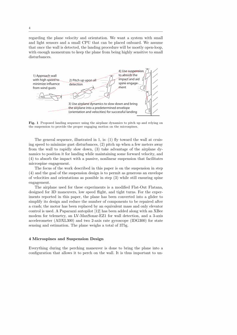
Fig. 1 Proposed landing sequence using the airplane dynamics to pitch up and relying onthe suspension to provide the proper engaging motion on the microspines.
The general sequence, illustrated in 1, is: (1) fly toward the wall at cruis-ing speed to minimize gust disturbances, (2) pitch up when a few meters awayfrom the wall to rapidly slow down, (3) take advantage of the airplane dy-namics to position it for landing while maintaining some forward velocity, and(4) to absorb the impact with a passive, nonlinear suspension that facilitatesmicrospine engagement.
The focus of the work described in this paper is on the suspension in step(4) and the goal of the suspension design is to permit as generous an envelopeof velocities and orientations as possible in step (3) while still ensuring spineengagement.
The airplane used for these experiments is a modified Flat-Out Flatana,designed for 3D maneuvers, low speed flight, and tight turns. For the exper-iments reported in this paper, the plane has been converted into a glider tosimplify its design and reduce the number of components to be repaired aftera crash; the motor has been replaced by an equivalent mass and only elevatorcontrol is used. A Paparazzi autopilot [12] has been added along with an XBeemodem for telemetry, an LV-MaxSonar-EZ1 for wall detection, and a 3-axisaccelerometer (ADXL300) and two 2-axis rate gyroscope (IDG300) for statesensing and estimation. The plane weighs a total of 375g.
4 Microspines and Suspension Design
Everything during the perching maneuver is done to bring the plane into aconfiguration that allows it to perch on the wall. It is thus important to un-
5
derstand the requirements of the adhesion system used, as di!erent systemshave di!erent requirements and tradeo!s. Microspines have been chosen forthis project as they can be used on a variety of surfaces [2,15], are lightweight,require no power, and provide directional adhesion, allowing repeated use andlow e!ort for engagement and disengagement. This section explains their re-quirements for adhering to a vertical surface and details the strategies used todesign a suspension satisfying the requirements for a range of initial velocitiesand orientations.
4.1 Microspine Requirements for Landing
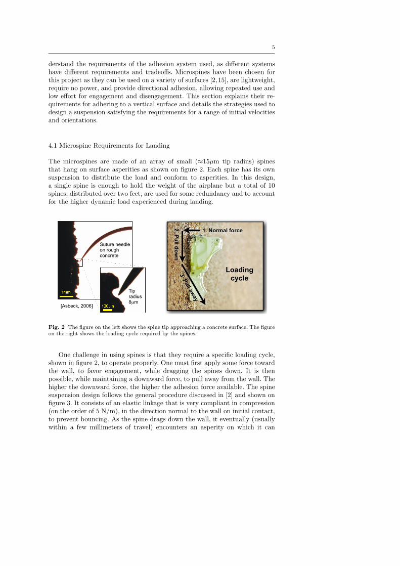
The microspines are made of an array of small (!15µm tip radius) spinesthat hang on surface asperities as shown on figure 2. Each spine has its ownsuspension to distribute the load and conform to asperities. In this design,a single spine is enough to hold the weight of the airplane but a total of 10spines, distributed over two feet, are used for some redundancy and to accountfor the higher dynamic load experienced during landing.
Spines
• Small spines that hang on asperities
• Individual suspensions distribute the load among spines
• Used on Spinybot and RISE
• Require small amount of normal force to engage
• Directional adhesion
• Completely passive!9
[Asbeck, 2006]
Suture needle on rough concrete
Tip radius 8µm
Loading cycle
Spines
• Small spines that hang on asperities
• Individual suspensions distribute the load among spines
• Used on Spinybot and RISE
• Require small amount of normal force to engage
• Directional adhesion
• Completely passive!9
[Aasbeck, 2006]
Suture needle on rough concrete
Tip radius 8µm
Loading cycle
1. Normal force
2. P
ull d
ow
n3. P
ull a
way
Fig. 2 The figure on the left shows the spine tip approaching a concrete surface. The figureon the right shows the loading cycle required by the spines.
One challenge in using spines is that they require a specific loading cycle,shown in figure 2, to operate properly. One must first apply some force towardthe wall, to favor engagement, while dragging the spines down. It is thenpossible, while maintaining a downward force, to pull away from the wall. Thehigher the downward force, the higher the adhesion force available. The spinesuspension design follows the general procedure discussed in [2] and shown onfigure 3. It consists of an elastic linkage that is very compliant in compression(on the order of 5 N/m), in the direction normal to the wall on initial contact,to prevent bouncing. As the spine drags down the wall, it eventually (usuallywithin a few millimeters of travel) encounters an asperity on which it can
6
cling. At this point, a load can be applied primarily tangential to the wall,but with an outward tensile component as well. When pulled in this direction,the suspension is sti!er (on the order of 100 N/m) but compliant enoughto promote load sharing between adjacent spines. For a given coe"cient offriction and surface roughness, the ratio between the maximum normal andtangential force defines a fixed loading volume, shown on figure 3. As discussedlater in Section 8, this means that for a plane to resist strong gusts of windit will ultimately be necessary to use preloaded pairs of spines to increase theavailable normal force. The third criterion in designing the mechanism andsetting the sti!nesses of the flexures is that the spines should not bend orrotate upwards as they are loaded, which could cause them to slip o! anyasperities that they find.
1
2
34 5
Approach volume
Loading ForcesVolume
y
x
Fig. 3 Representation of the microspines. The spring elements 3 & 4 contribute to thetangential compliance, while element 5 provides the relatively soft compliance normal to thewall. The approach volume is mostly a function of the asperities’ geometry while the loadingvolume depends on the coe!cient of friction and the asperity geometry.
The ramifications of the spine design for the control of the airplane are thatit should have a small velocity normal to the wall (to prevent bouncing) anda moderate downward velocity to load the spines once they make contact. Inaddition, the orientation of the plane should be maintained within some fixedrange corresponding to desirable orientations of the spines as they contact thewall. In addition, it is desirable for the center of mass of the plane to be keptclose to the wall after contact.
7
4.2 Preventing Vertical Rebound
Although the small elastic “toe” mechanisms holding the spines help to pre-vent bouncing in the direction normal to the wall, they have a very limitedsuspension travel (a few millimeters), requiring an additional suspension inthe “legs” of the landing gear interposed between the spines and the plane.More significantly, there is the danger of rebounding in the vertical direction,parallel to the wall, where the velocities and forces are higher.
Following the observation during initial tests that vertical rebound was themain cause of failure, three design goals were formulated for a good suspension:
1. Minimize the maximum force (Fmax) in the vertical direction to allow fora lightweight structure.
2. Minimize the suspension travel (-x).3. Prevent spine rebound (negative vertical force) during the landing.
A solution satisfying these goals is to have a constant force for the fullduration of the landing. Unfortunately, the force pattern that can be generateddepends on the components available and, in the case of a small UAV, the taskbecomes challenging due to the size and weight constraints.
0 0.05 0.1 0.15 0.2!0.03
!0.02
!0.01
0
Po
sit
ion
Air
pla
ne
(m
)
0 0.05 0.1 0.15 0.2!20
0
20
40
Fo
rce
on
sp
ine
s(N
)
time (sec)
Fric = 33 N
! = 0.62
! = 0.29, Fric = 11 N
Spine rebound region
FB
K
M
g
v!
x
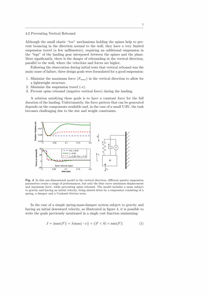
Fig. 4 In this one-dimensional model in the vertical direction, di"erent passive suspensionparameters create a range of performances, but only the blue curve minimizes displacementand maximum force, while preventing spine rebound. The model includes a mass subjectto gravity and having an initial velocity, being slowed down by a suspension consisting of aspring, a damper and a Coulomb friction term.
In the case of a simple spring-mass-damper system subject to gravity andhaving an initial downward velocity, as illustrated in figure 4, it is possible towrite the goals previously mentioned in a single cost function minimizing:
where ! is a weighting factor that can be adjusted to trade-o! betweenthe maximum force and suspension travel criteria. A Nelder-Mead simplexcan then be used to minimize this cost function. The resulting trade-o! curveobtained by varying ! is shown in figure 5. This figure shows that as the max-imum allowed displacement of the suspension is reduced, the damping ratiomust be increased accordingly. This is due to the shorter landing time, cor-responding to shorter suspension displacement, during which the damper candissipate kinetic energy. This is unfavorable as a high damping ratio suspen-sion creates a high initial force that decreases rapidly (see red curve in figure4), requiring a sturdy structure to accommodate the initial force.
0.5 1 1.5 2 2.5 3 3.5 4 4.510
20
30
40
50
60
70
80
90
100
Maximum displacement (cm)
Ma
xim
um
fo
rce
(N
), !
" 1
00
Trade!off curve
! " 100
Fig. 5 Trade-o" curve between maximum displacement and maximum force for a spring-damper suspension preventing rebounds. Also shown is the damping ratio required at anypoint in the trade-o" curve. Results are shown for a 320g airplane subject to an initialvelocity of -2m/s
4.2.1 Spring, Damper and Coulomb Friction
In order to prevent the high initial force caused by a strong viscous damper,a pure coulomb friction suspension could be used. However, a pure coulombfriction also has practical drawbacks: it does not return to a single equilibriumposition after landing and it is di"cult to adjust the level of friction precisely.In addition, it requires a hard stop to limit the suspension travel. Fortunately,it is possible to combine coulomb friction with a spring and damper and stillobtain a near optimal solution.
Knowing the desired maximum force (Fmax), the touchdown velocity (vi),the desired spring sti!ness (k) and assuming that we can design a near con-stant force suspension, the trajectory of the airplane during landing can beapproximated by a mass subject to constant acceleration:
9
v(t) =!
Fmax
m" g
"t + vi (2)
xmax =12
!Fmax
m" g
"t2 + vit (3)
Combining, we get an expression for the maximum compression of thesuspension when v(t) = 0:
xmax = "v2i
2m
Fmax "mg(4)
To obtain an approximately constant force profile on the spines during thelanding, the initial force, a combination of damper and coulomb forces, mustbe equal to the force at maximum compression, which is a combination of thespring and coulomb forces. Thus:
Fmax = "kxmax + Ffric = "bvi + Ffric (5)(6)
From these equations, it is possible to solve for the required damping co-e"cient (b), the friction force (Ffric) and the damping ratio ("):
b =kxmax
vi(7)
Ffric = Fmax + kxmax (8)
" =xmax
2vi
#k
m(9)
A suspension designed using these criteria provides an almost constantforce during landing. It is more robust to variations in initial velocity andreturns to its default state as long as Ffric > "kxmax"mg (where xmax < 0).As an example, for a maximum force of 31 N, a spring sti!ness of 860 N/mand a initial speed of -2 m/s as parameters, these equations lead to a dampingratio of 0.29, a friction force of 11.2N and a maximum displacement of 2.3 cm.
4.3 Non-Linear Damping
While the previous sections show what parameters are necessary to providegood spine engagement, the derivation assumes constant value parameters thatcan be varied independently. Furthermore, the size and weight constraints ona small UAV severely limit the kinds of components that can be used in asuspension and favor lightweight viscoelastic materials.
However, some viscoelastic materials have non-linear properties that canbe advantageous for lightweight suspensions. It can be shown, as in [1], that
10
in the case of a simple spring-damper suspension subject to an initial velocity,the force on the spines would be constant if the damping coe"cient is equal tob = (Fmax"kx(t))/v(t). This means that a low damping coe"cient is desirableinitially (high velocity at contact), and that it should increased as the planeslows down.
0.05 0.1 0.15 0.2 0.25 0.35
10
15
20
25
30
35
Max. Velocity (m/s)
Vis
co
us
Da
mp
ing
(N
s/m
)
Rubber
CONFOR foam
Fig. 6 The damping coe!cient of materials varies in di"erent ways. Rubber shows a nearconstant damping coe!cient for the range of speed experienced by the suspension whilepink CONFOR foam damping is significantly lower at high velocity.
An example of this kind of material can be found in CONFOR foam, aslow-recovery urethane foam. Although not having exactly the damping char-acteristics required to provide a perfectly constant force, figure 6 shows thatthis material has a damping coe"cient that decreases with increasing speedcompared to the near constant damping of rubber. These materials were testedby subjecting them to a sine wave of varying amplitude, to keep the amount ofdamping and spring force roughly proportional during the testing. An AdeptOne robotic arm was used to generate the motions and forces were measuredwith a JR3 wrist force sensor. The section tested measured 25x25mm for pinkCONFOR foam and 7x2mm for the rubber, both 10cm in length.
4.4 Suspension testing
Several foam suspensions were built and tested to obtain a rough estimate ofthe envelope of possible landing configurations, as the one shown in figure 7.No extensive characterization has been done yet, but the maximum values oforientation and velocity were recorded from 30 flights and are summarized intable 1. The lower limits of pitch angle and vy are currently set by the ankledesign joint placement and could be improved in future designs.
11Leg Structure
Foam
hip
Balsa/Carbon
femur
Sorbothane
knee
Carbon
tibia
Foam
ankle
Spines
Attachment
points
14
Fig. 7 Suspension made of slow-recovery urethane foam. The ankle joint provides a fastresponse to the surface profile, while the hip and knee joint absorb the impact without anyrebound.
The suspension could probably allow landing with a horizontal velocity,vx, higher than 3m/s, but this hasn’t been observed due to drag at high pitchangles drastically decelerating the plane; initial velocities have simply not beenlarge enough to result in vx above 3m/s at contact. Pitch angles higher than105 degrees also have not been observed, as the plane tends to return to 90degrees pitch.
Table 1 Values of orientation and velocity observed at touchdown during 30 successfullandings on concrete wall. Minimum pitch and minimum vy are currently limited by thelinkage design.
Envelop parameters Minimum Maximum
Pitch 60 deg 105 degPitch rate 0 200 deg/s
vx - 3 m/svy 0 m/s 2.7 m/s
5 Airplane Trajectory
The relatively wide ranges of orientation and velocity at which the plane canperch impose relatively few constraints on the trajectory. This has allowed usto use the natural dynamics of the airplane platform. As shown in figure 8,the natural response of the plane flying at about 9 m/sec to an elevator up(45 degrees) command is as follows:
12
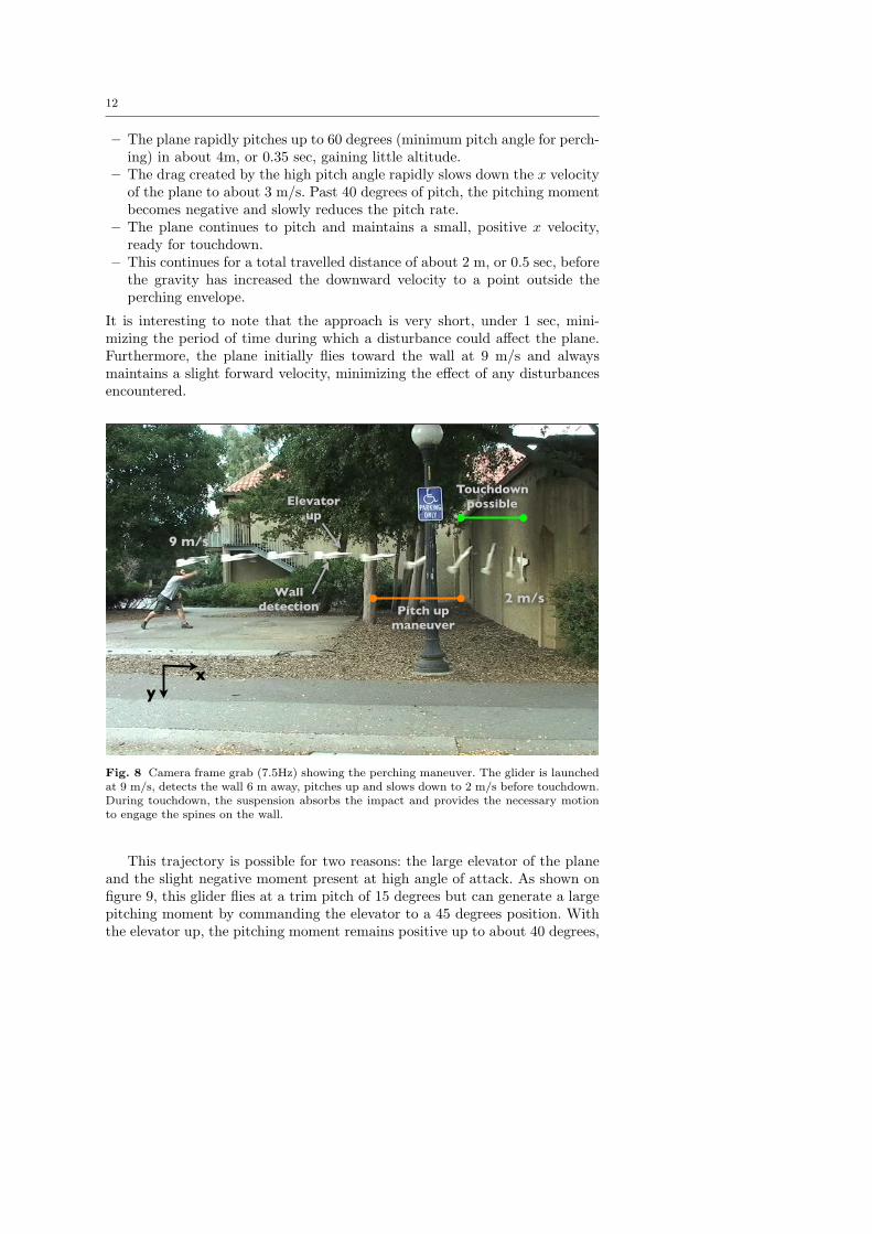
– The plane rapidly pitches up to 60 degrees (minimum pitch angle for perch-ing) in about 4m, or 0.35 sec, gaining little altitude.
– The drag created by the high pitch angle rapidly slows down the x velocityof the plane to about 3 m/s. Past 40 degrees of pitch, the pitching momentbecomes negative and slowly reduces the pitch rate.
– The plane continues to pitch and maintains a small, positive x velocity,ready for touchdown.
– This continues for a total travelled distance of about 2 m, or 0.5 sec, beforethe gravity has increased the downward velocity to a point outside theperching envelope.
It is interesting to note that the approach is very short, under 1 sec, mini-mizing the period of time during which a disturbance could a!ect the plane.Furthermore, the plane initially flies toward the wall at 9 m/s and alwaysmaintains a slight forward velocity, minimizing the e!ect of any disturbancesencountered.
Touchdownpossible
Pitch upmaneuver
Elevatorup
Walldetection
9 m/s
2 m/s
xy
Fig. 8 Camera frame grab (7.5Hz) showing the perching maneuver. The glider is launchedat 9 m/s, detects the wall 6 m away, pitches up and slows down to 2 m/s before touchdown.During touchdown, the suspension absorbs the impact and provides the necessary motionto engage the spines on the wall.
This trajectory is possible for two reasons: the large elevator of the planeand the slight negative moment present at high angle of attack. As shown onfigure 9, this glider flies at a trim pitch of 15 degrees but can generate a largepitching moment by commanding the elevator to a 45 degrees position. Withthe elevator up, the pitching moment remains positive up to about 40 degrees,
13
and then becomes slightly negative, slowing down the pitching motion. The keyto a successful maneuver is to create just enough initial angular momentumto reach a pitch angle of 90 degrees with zero pitch rate.
One could also think about a two step maneuver: commanding the elevatorup to its maximum to create a higher pitching rate, followed by a secondelevator command to slow down the plane to zero pitch rate when a pitch of 90degrees is reached. This would have the advantage of keeping the maneuver asshort as possible, but would require pitch sensing and hasn’t been implementedyet.
6 Sensors and Control
The trajectory shown on figure 8 is particularly simple from a sensing point ofview. Because the plane stops its pitching motion when it approaches 90 deg(a perfect pitch angle for landing), this maneuver can be executed without anypitch sensor. The only sensing requirement for a fully autonomous landing is tomeasure the distance from the wall to trigger the maneuver at the right time.Because of the large available touchdown region, the sensor doesn’t need to beparticularly accurate nor to monitor the wall position as the plane is pitchingup. Furthermore, since the wall distance sensor is only used for triggering themaneuver, any time delay in the sensor does not a!ect the maneuver as longas the delay is known.
Considering the delay in the servo controlling the elevator (roughly 0.1 sec,or 1 m), the distance to pitch up (4 m) and trying to land in the middle ofthe touchdown region (2 m wide), the maneuver should start from about 6meters away from the wall. The entire maneuver is open-loop, consisting ofjust moving the elevator up to 45 deg when the plane is approximately 6 maway from the wall. Fortunately, the LV-MaxSonar-EZ1 ultrasound sensor hasa range of 6.45m, a 20Hz update rate, is relatively accurate, and has a massof only 7 g.
The plane also has a 3-axis accelerometer (ADXL330) and two 2-axis rategyroscope (IDG300) onboard. These sensors are not used for control, but areuseful to measure the motion of the airplane for analysis, as shown in figure9. The accelerometer measurements are first combined with the rate gyro byusing a second order complementary filter:
#comp =($s + 1)2
($s + 1)2# =
$s
($s + 1)2#̇rate gyro +
2$s + 1($s + 1)2
#gravity (10)
This filter combines the pitch measurement from the low frequency signalfrom the accelerometer (gravity measurement) with the high frequency rategyro measurement to create a signal that doesn’t drift, is immune to otheracceleration than gravity and responds to fast change. The frequency at whichthe transition occurs is chosen by the parameter $ and has been experimentallychosen to be 0.1. Finally, using the pitch angle, the measurement from the
14
0 0.2 0.4 0.6 0.8 1 1.2 1.4 1.6
0
50
100
time (sec)
Pit
ch
(d
eg
)
0 0.2 0.4 0.6 0.8 1 1.2 1.4 1.60
2
4
6
Wa
ll D
ista
nc
e (
m)
time (sec)
0 0.2 0.4 0.6 0.8 1 1.2 1.4 1.6
0
2
4
6
8
time (sec)
vx (
m/s
)
0 20 40 60 80 100 120 140 160 180!0.5
0
0.5
1
Mo
me
nt
(Nm
)
Angle of attack (deg)
Trim flight
Elevator up
Walldetection
Throwing
Autonomous flight
Pitch upmaneuver
Touch Down
Fig. 9 Data collected during autonomous perching. The plane is released at 0.58 sec, glidestoward the wall, detects the wall at 0.82 sec (6 m away from the wall) and starts pitchingup. Pass 50 degrees, the plane rapidly slow down both its x velocity and its pitch rate. Itthen touch the wall at an pitch angle of 105 deg and a x velocity of 1 m/s. Some ripples arepresent in the wall distance sensor, thus the importance of having a robust maneuver andsuspension. The pitching moment curve shows the trim flight condition (in blue), the highpitching moment created by the elevator up (red curve from 15-40 degrees) and the smallnegative moment that reduce the pitch rate to zero at about 90 degrees.
15
accelerometer can be integrated to get the x and y velocities. Examples ofthese measurements can be seen in figure 9
7 Results and Future Work
The early result reported in this paper is an integrated system. The non-linearsuspension made from slow-recovery urethane is lightweight and robust whileminimizing the impact forces and providing the proper engaging motion forthe spines. Most importantly, the suspension-spines combination allows for awide envelope of incoming velocities and orientations at touchdown which canbe easily reached by using the natural dynamics of the airplane. The highinitial positive pitching moment created by the upward elevator command isbalanced by the small negative recovery moment that maximizes the plane’stime in a favorable landing attitude. A typical perching maneuver, from walldetection to touchdown, lasts less than one second and reduces the speed ofthe airplane from 9 m/s to less than 2 m/s at touchdown. Figure 9 shows datacollected during an autonomous landing and figure 8 shows a frame captureof the landing.
With such a system, it is possible to perch both autonomously and man-ually. A human can quickly learn the timing of the maneuver and perch theairplane on a wall. Approximately 30 successful landings have been performedso far: 20 manually operated and 10 autonomously controlled. The successrate is approximately 80% and it is possible to achieve many successive land-ings without having to tune or repair the system. The main cause of failureis false wall detection from the sensor, causing an early pitch-up maneuverwhich results in the plane not reaching the wall. The current distance sensoris operating near its maximum range, and the maneuver needs to be startedas soon as something is detected. It is thus di"cult to apply any kind of filterto prevent false detection and increase robustness.
The second cause of failure is from the plane pitching up too late, thushitting the wall at a pitch angle of less than 60 degrees and breaking thesuspension. This failure mode has been observed during manual landing, buthas never been observed with autonomous perching.
The resulting perching system consisting of the foam suspension, spinesand ultrasonic sensor weighs only 28g, a small percentage of the 375g weightof the total airplane. With optimization of the spines and structure, we believethat the weight can be reduced to less than 20g.
8 Conclusions and Future Work
This paper presents the design of an integrated system allowing a small, fixed-wing plane to land and perch on vertical suraces. The motivations are togreatly increase mission life and provide the plane with a stable, secure locationthat is relatively free of debris. The ability to grip vertical surfaces relies upon
16
arrays of compliant microspines, adapted from climbing robots. The particularrequirements of the spines for reliably engaging and gripping a surface lead tocorresponding requirements for the incoming velocity and orientation of theplane and, most importantly, to requirements for a suspension that will asorbenergy, maintain a steady engagement force, and prevent bouncing.
We present the design of a nonlinear damped suspension that meets theserequirements, allowing a very simple fixed-wing glider to land with a relativelyhigh success rate. 1
Immediate work on the perching system will include increasing the wallsensor robustness and optimizing the trajectory to perform the maneuver ina shorter distance and maximize the amount of time over which touchdown ispossible. We also plan to study the e!ect of adding a propeller and performingthe perching maneuver when subjected to sidewinds.
Looking further ahead, a number of extensions are desirable to convert thistechnology into a practical solution for small UAVs. First, as soon as the planecomes to rest, it is desirable to engage a second set of spines that pulls upward,in opposition to the first set. By increasing the internal force between theseopposed sets of spines, it becomes possible to sustain a much larger normalforce due, for example, to gusts of wind. In preliminary tests, forces of severalNewtons in the normal direction have been achieved.
The strategy of landing on buildings can also be extended to perching onother vertical surfaces such as tree trunks, which are actually easier to gripbut much less regular, requiring a greater suspension travel. Another inter-esting possibility is to use directional dry adhesives, as used in gecko-inspiredclimbing robots [11] for climbing surfaces such as glass and smooth panels. Thedry adhesives are conceptually similar to spines, but have narrower tolerancesin terms of the required approach velocity and loading strategy; consequentlythey will require a more exact suspension design and more attention in con-trolling the approach velocity of the plane.
Finally, we need to address the ability to resume flight. One solution maybe to use a small actuator to store elastic energy in the suspension “legs” andjump o! the wall in a flight that is initially inverted, rolling to an uprightposition once away from the wall.
Acknowledgements Alexis Lussier Desbiens is supported by the Natural Sciences andEngineering Research Council of Canada and the Organization of American States, withadditional support from DARPA DSO. We would also like to thank Taylor Cone and themembers of BDML (Alan Asbeck, Barrett Heyneman, Dan Aukes and others) at Stanfordfor all their help in conducting the experiments reported here.
References
1. Akella, P.N.: Contact mechanics and the dynamics of manipulation. PhD in MechanicalEngineering, Stanford University (1992)
1 A version of the same spined toes and leg suspension has also been taken to MIT andretrofitted to the planes reported in [5], with similar results.
17
2. Asbeck, A.T., Kim, S., Cutkosky, M., Provancher, W.R., Lanzetta, M.: Scaling hardvertical surfaces with compliant microspine arrays. International Journal of RoboticsResearch 25(12), 14 (2006)
3. Byrnes, G., Lim, N.T.L., Spence, A.J.: Take-o" and landing kinetics of a free-ranginggliding mammal, the malayan colugo (galeopterus variegatus). Proceedings of the RoyalSociety B: Biological Sciences 275(1638), 1007–1013 (2008)
4. Caple, G., Balda, R.P., Willis, W.R.: The physics of leaping animals and the evolutionof preflight. The American Naturalist 121, 455–467 (1983)
5. Cory, R., Tedrake, R.: Experiments in fixed-wing uav perching. Proceedings of theAIAA Guidance, Navigation, and Control Conference (2008)
6. Frank, A., McGrew, J.S., Valenti, M., Levine, D., How, J.P.: Hover, transition, and levelflight control design for a single-propeller indoor airplane. AIAA Guidance, Navigationand Control Conference (2007)
7. Green, W., Oh, P.: A mav that flies like an airplane and hovers like a helicopter. Ad-vanced Intelligent Mechatronics. Proceedings (2005)
8. Green, W., Oh, P.: A fixed-wing aircraft for hovering in caves, tunnels, and buildings.American Control Conference (2006)
9. Green, W., Oh, P.: Autonomous hovering of a fixed-wing micro air vehicle. IEEEInternational Conference of Robotics and Automation (2008)
10. Illingworth, L., Reinfeld, D.: Vortex attractor - US 6,565,321 B1. United States Patentp. 40 (2003)
11. Kim, S., Spenko, M., Trujillo, S., Heyneman, B., Santos, D., Cutkosky, M.R.: Climbingwith directional adhesion. IEEE Transactions on Robotics 24 (2008)
12. Paparazzi: Paparazzi, the free autopilot. http://paparazzi.enac.fr (2008). URL http://paparazzi.enac.fr
13. Paskins, K.E., Bowyer, A., Megill, W.M., Scheibe, J.S.: Take-o" and landing forcesand the evolution of controlled gliding in northern flying squirrels glaucomys sabrinus.Journal of Experimental Biology 210(8), 1413–1423 (2007)
14. Roberts, J., Cory, R., Tedrake, R.: On the controllability of fixed-wing perching. Amer-ican Controls Conference (2009)
15. Spenko, M., Haynes, G., Saunders, J., Cutkosky, M., Rizzi, A., Full, R.: Biologicallyinspired climbing with a hexapedal robot. Journal of Field Robotics (2008)
16. Wickenheiser, A., Garcia, E.: Longitudinal dynamics of a perching aircraft. Journal ofAircraft (2006)
17. Wickenheiser, A., Garcia, E.: Perching aerodynamics and trajectory optimization. Pro-ceedings of SPIE (2007)
18. Wickenheiser, A.M., Garcia, E.: Optimization of perching maneuvers through vehiclemorphing. J. Guidance 31(4), 815–823 (2008). DOI 10.2514/1.33819