Page 1
www.strath.ac.uk/space
LASER BEES A Concept for Asteroid Deflection & Hazard Mitigation
Alison Gibbings, Advanced Space Concepts Laboratory, University of Strathclyde
Dr Massimiliano Vasile, Advanced Space Concepts Laboratory, University of Strathclyde
Dr John-Mark Hopkin, Institute of Photonics, University of Strathclyde
Dr David Burns, Institute of Photonics, University of Strathclyde
Dr Ian Watson, Systems, Power and Energy, School of Engineering, University of Glasgow
Page 2
[email protected] @strath.ac.uk [email protected]
CONTENTS
Asteroids
Risk
Laser
Ablation
Modelling
Technique
Experiment Results &
Conclusion
Page 4
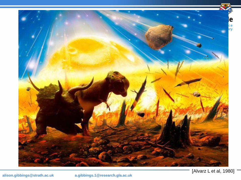
[email protected] @strath.ac.uk [email protected] [Alvarz L et al, 1980]
Page 5
[email protected] @strath.ac.uk [email protected]
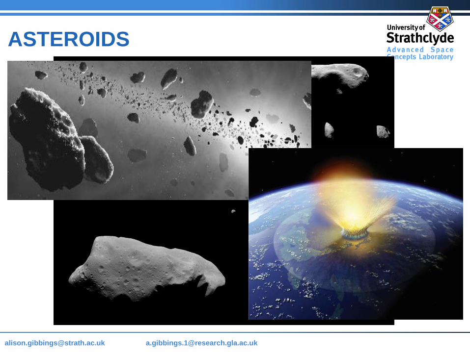
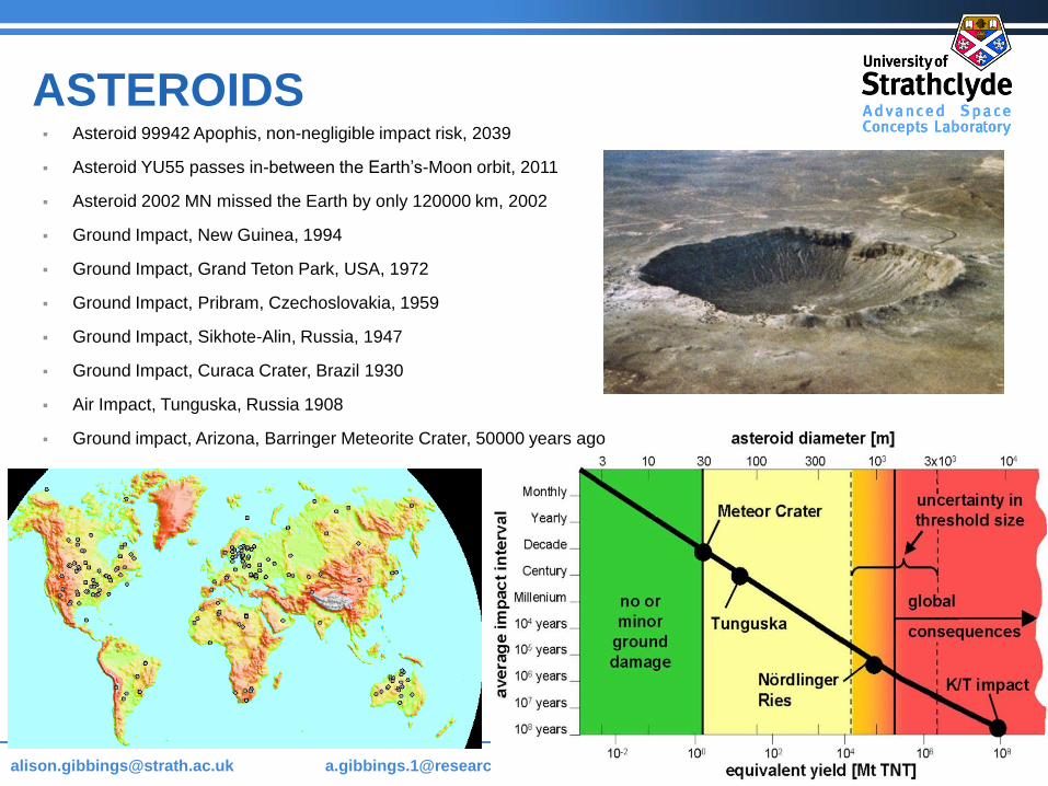
ASTEROIDS Asteroid 99942 Apophis, non-negligible impact risk, 2039
Asteroid YU55 passes in-between the Earth’s-Moon orbit, 2011
Asteroid 2002 MN missed the Earth by only 120000 km, 2002
Ground Impact, New Guinea, 1994
Ground Impact, Grand Teton Park, USA, 1972
Ground Impact, Pribram, Czechoslovakia, 1959
Ground Impact, Sikhote-Alin, Russia, 1947
Ground Impact, Curaca Crater, Brazil 1930
Air Impact, Tunguska, Russia 1908
Ground impact, Arizona, Barringer Meteorite Crater, 50000 years ago
Page 6
[email protected] @strath.ac.uk [email protected]
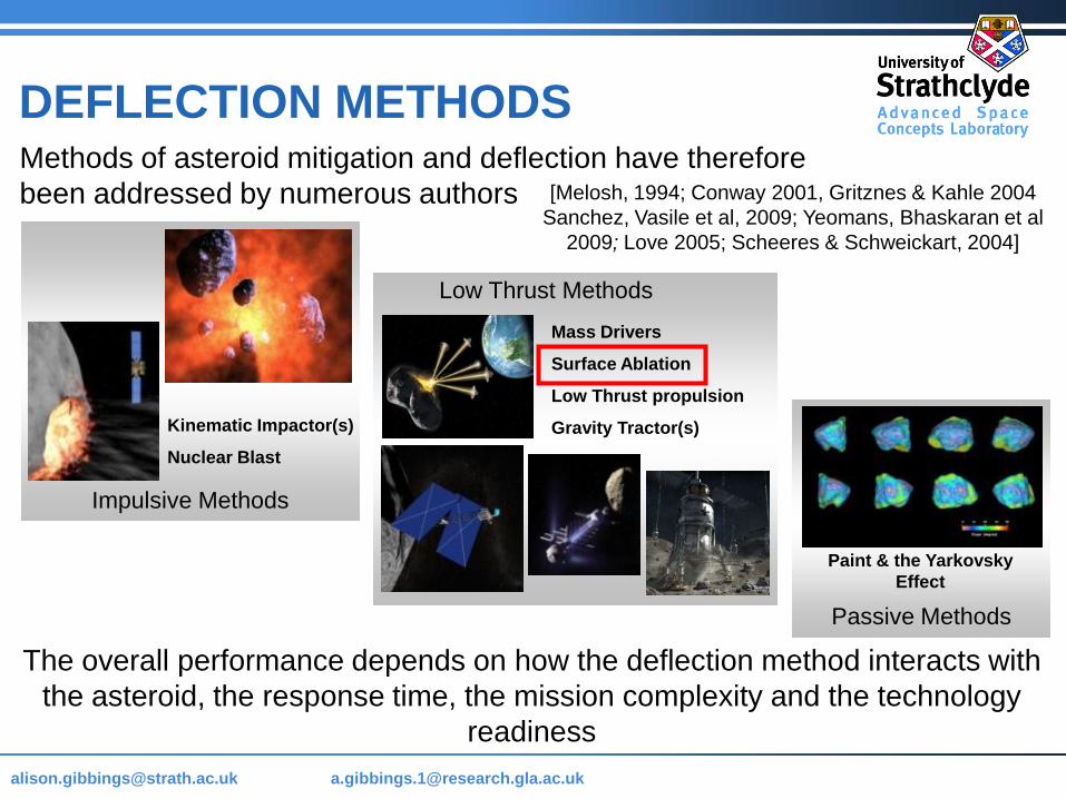
Methods of asteroid mitigation and deflection have therefore
been addressed by numerous authors
DEFLECTION METHODS
[Melosh, 1994; Conway 2001, Gritznes & Kahle 2004
Sanchez, Vasile et al, 2009; Yeomans, Bhaskaran et al
2009; Love 2005; Scheeres & Schweickart, 2004]
Nuclear Blast
Kinematic Impactor(s)
Impulsive Methods
Mass Drivers
Surface Ablation
Low Thrust propulsion
Gravity Tractor(s)
Low Thrust Methods
Paint & the Yarkovsky
Effect
Passive Methods
Kinematic Impactor(s)
Nuclear Blast
The overall performance depends on how the deflection method interacts with
the asteroid, the response time, the mission complexity and the technology
readiness
Page 7
[email protected] @strath.ac.uk [email protected]
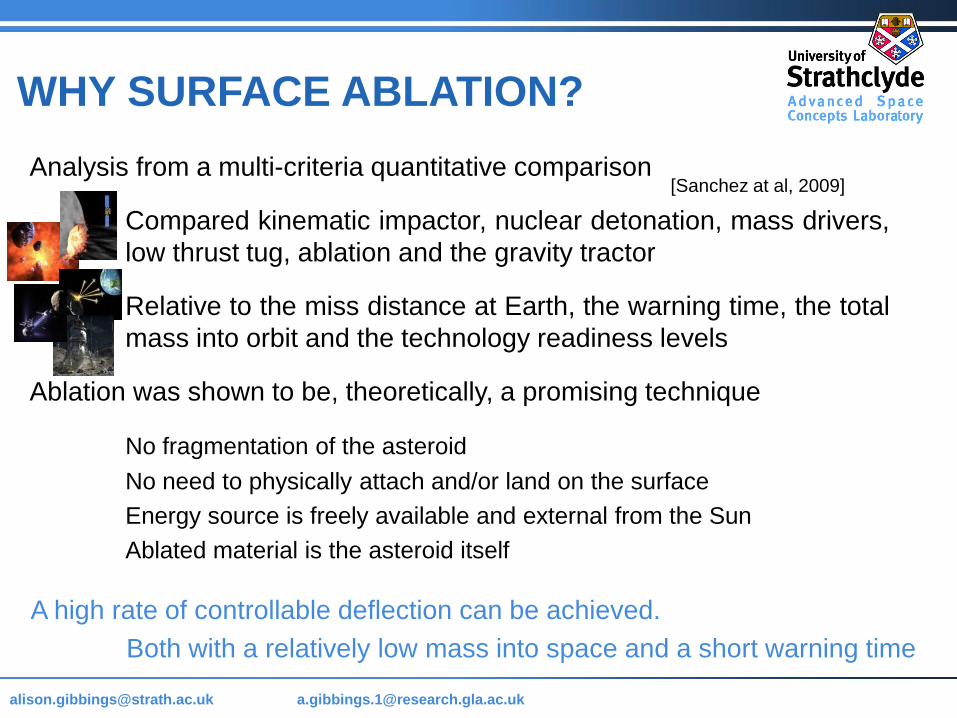
WHY SURFACE ABLATION?
Analysis from a multi-criteria quantitative comparison
Compared kinematic impactor, nuclear detonation, mass drivers,
low thrust tug, ablation and the gravity tractor
Relative to the miss distance at Earth, the warning time, the total
mass into orbit and the technology readiness levels
Ablation was shown to be, theoretically, a promising technique
No fragmentation of the asteroid
No need to physically attach and/or land on the surface
Energy source is freely available and external from the Sun
Ablated material is the asteroid itself
[Sanchez at al, 2009]
A high rate of controllable deflection can be achieved.
Both with a relatively low mass into space and a short warning time
Page 8
[email protected]
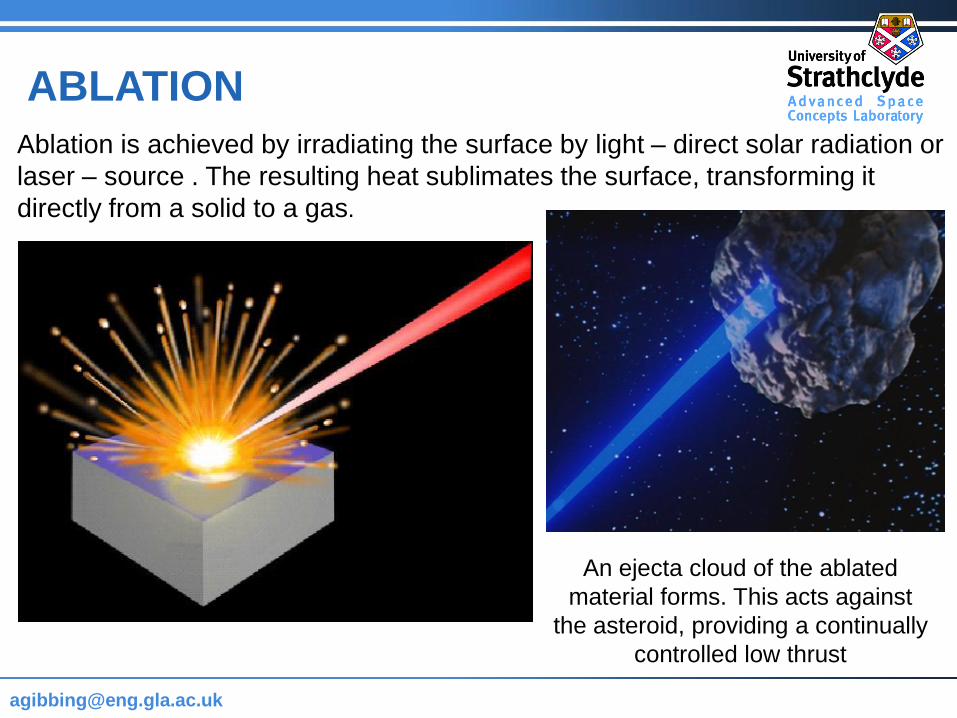
ABLATION
Ablation is achieved by irradiating the surface by light – direct solar radiation or
laser – source . The resulting heat sublimates the surface, transforming it
directly from a solid to a gas.
An ejecta cloud of the ablated
material forms. This acts against
the asteroid, providing a continually
controlled low thrust
Page 9
[email protected] @strath.ac.uk [email protected]
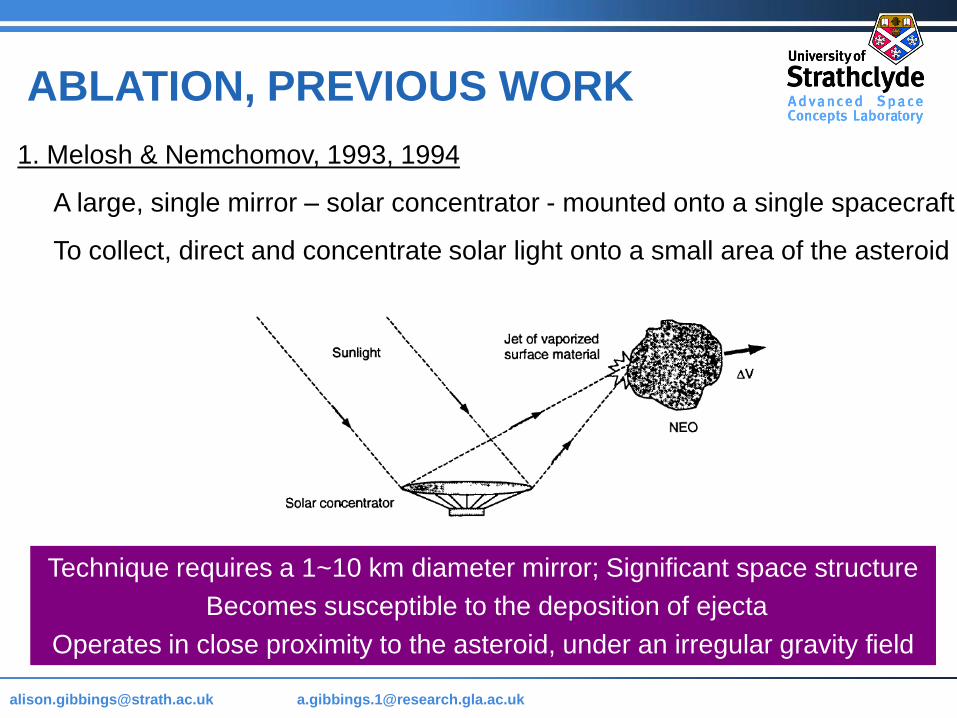
1. Melosh & Nemchomov, 1993, 1994
A large, single mirror – solar concentrator - mounted onto a single spacecraft
To collect, direct and concentrate solar light onto a small area of the asteroid
ABLATION, PREVIOUS WORK
Technique requires a 1~10 km diameter mirror; Significant space structure
Becomes susceptible to the deposition of ejecta
Operates in close proximity to the asteroid, under an irregular gravity field
Page 10
[email protected] @strath.ac.uk [email protected]
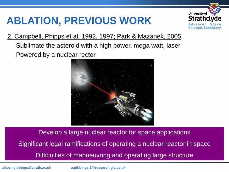
2. Campbell, Phipps et al, 1992, 1997; Park & Mazanek, 2005
Sublimate the asteroid with a high power, mega watt, laser
Powered by a nuclear rector
ABLATION, PREVIOUS WORK
Develop a large nuclear reactor for space applications
Significant legal ramifications of operating a nuclear reactor in space
Difficulties of manoeuvring and operating large structure
Page 11
[email protected] @strath.ac.uk [email protected]
ABLATION, PREVIOUS WORK
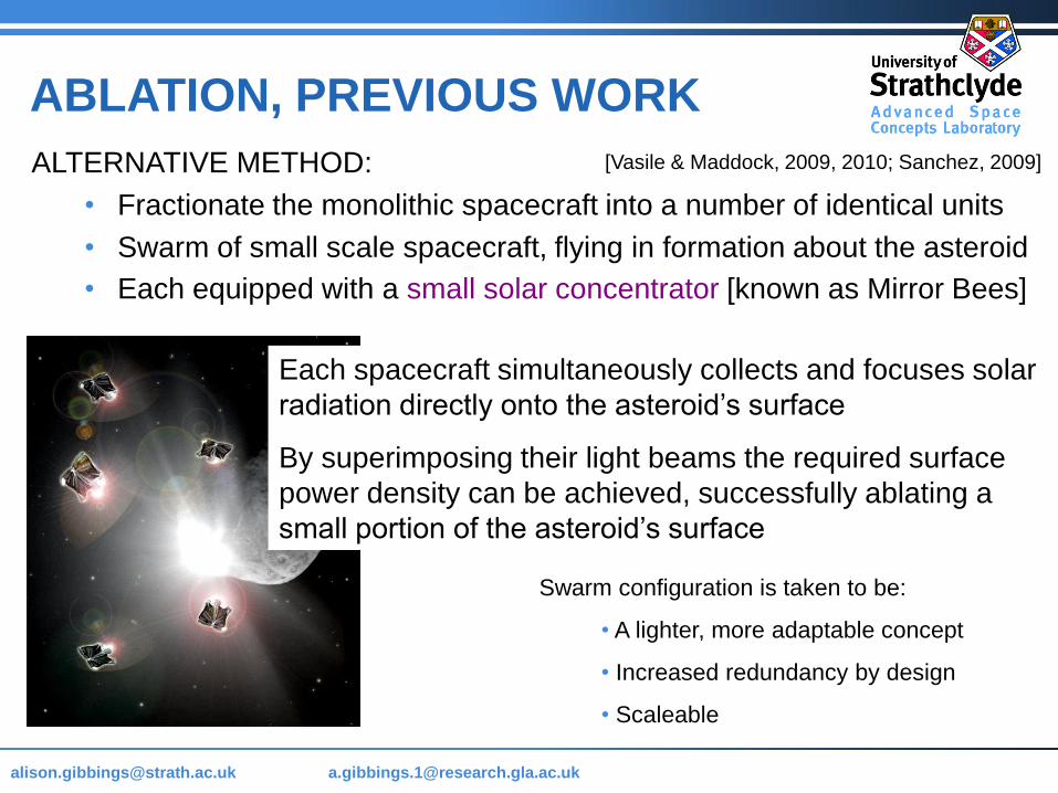
ALTERNATIVE METHOD:
• Fractionate the monolithic spacecraft into a number of identical units
• Swarm of small scale spacecraft, flying in formation about the asteroid
• Each equipped with a small solar concentrator [known as Mirror Bees]
Each spacecraft simultaneously collects and focuses solar
radiation directly onto the asteroid’s surface
By superimposing their light beams the required surface
power density can be achieved, successfully ablating a
small portion of the asteroid’s surface
Swarm configuration is taken to be:
• A lighter, more adaptable concept
• Increased redundancy by design
• Scaleable
[Vasile & Maddock, 2009, 2010; Sanchez, 2009]
Page 12
[email protected] @strath.ac.uk [email protected]
ABLATION, PREVIOUS WORK
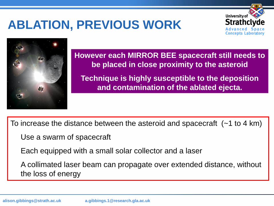
However each MIRROR BEE spacecraft still needs to
be placed in close proximity to the asteroid
Technique is highly susceptible to the deposition
and contamination of the ablated ejecta.
To increase the distance between the asteroid and spacecraft (~1 to 4 km)
Use a swarm of spacecraft
Each equipped with a small solar collector and a laser
A collimated laser beam can propagate over extended distance, without
the loss of energy
Page 13
[email protected] @strath.ac.uk [email protected]
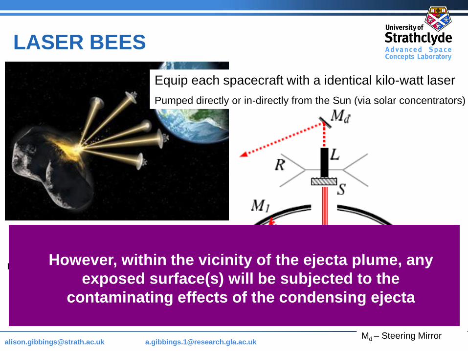
LASER BEES
Equip each spacecraft with a identical kilo-watt laser
Pumped directly or in-directly from the Sun (via solar concentrators)
Require two lightweight deployable
mirrors to concentrate the solar radiation
And a steering mirror to target the laser
onto the surface of the asteroid.
M1 – Primary Mirror
M2 – Secondary Mirror
S – Solar cells
L – Laser
R – Radiators
Md – Steering Mirror
However, within the vicinity of the ejecta plume, any
exposed surface(s) will be subjected to the
contaminating effects of the condensing ejecta
Page 14
[email protected] @strath.ac.uk [email protected]
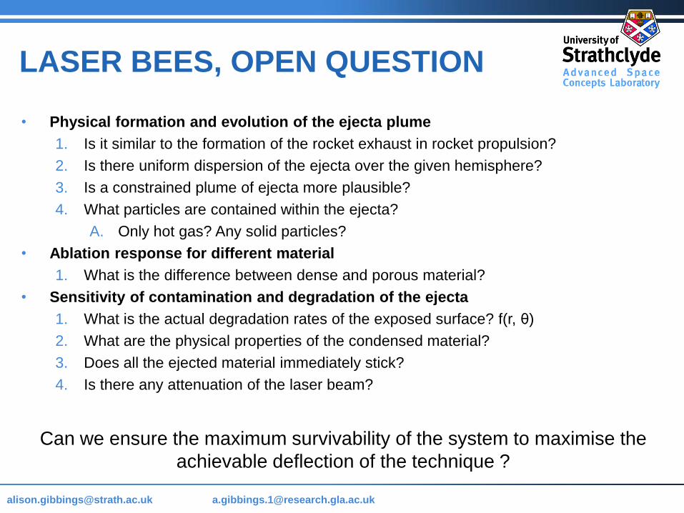
LASER BEES, OPEN QUESTION
• Physical formation and evolution of the ejecta plume
1. Is it similar to the formation of the rocket exhaust in rocket propulsion?
2. Is there uniform dispersion of the ejecta over the given hemisphere?
3. Is a constrained plume of ejecta more plausible?
4. What particles are contained within the ejecta?
A. Only hot gas? Any solid particles?
• Ablation response for different material
1. What is the difference between dense and porous material?
• Sensitivity of contamination and degradation of the ejecta
1. What is the actual degradation rates of the exposed surface? f(r, θ)
2. What are the physical properties of the condensed material?
3. Does all the ejected material immediately stick?
4. Is there any attenuation of the laser beam?
Can we ensure the maximum survivability of the system to maximise the
achievable deflection of the technique ?
Page 15
[email protected] @strath.ac.uk [email protected]
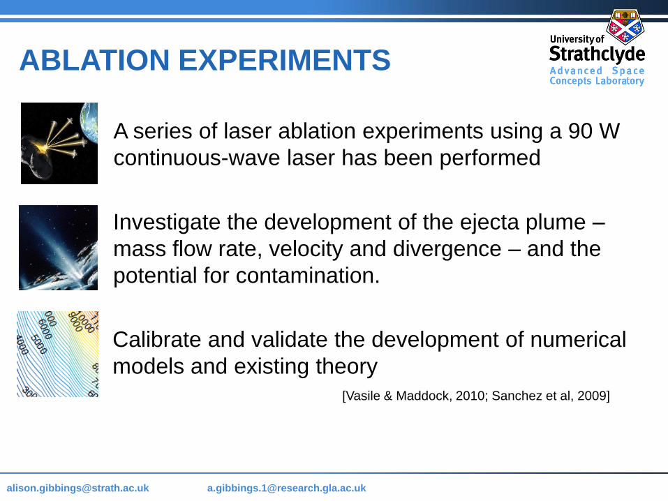
[Vasile & Maddock, 2010; Sanchez et al, 2009]
A series of laser ablation experiments using a 90 W
continuous-wave laser has been performed
Investigate the development of the ejecta plume –
mass flow rate, velocity and divergence – and the
potential for contamination.
Calibrate and validate the development of numerical
models and existing theory
ABLATION EXPERIMENTS
Page 16
[email protected] @strath.ac.uk [email protected] Name as Header & Footer
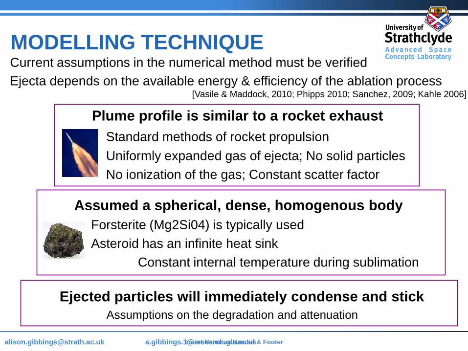
Current assumptions in the numerical method must be verified
MODELLING TECHNIQUE
[Vasile & Maddock, 2010; Phipps 2010; Sanchez, 2009; Kahle 2006]
Ejecta depends on the available energy & efficiency of the ablation process
Plume profile is similar to a rocket exhaust
Standard methods of rocket propulsion
Uniformly expanded gas of ejecta; No solid particles
No ionization of the gas; Constant scatter factor
Assumed a spherical, dense, homogenous body
Forsterite (Mg2Si04) is typically used
Asteroid has an infinite heat sink
Constant internal temperature during sublimation
Ejected particles will immediately condense and stick
Assumptions on the degradation and attenuation
Page 17
[email protected] @strath.ac.uk [email protected] Name as Header & Footer
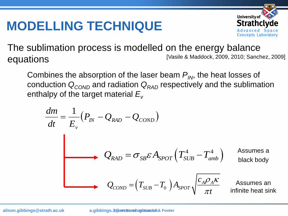
The sublimation process is modelled on the energy balance
equations
Combines the absorption of the laser beam PIN, the heat losses of
conduction QCOND and radiation QRAD respectively and the sublimation
enthalpy of the target material Ev
CONDRADIN
v
QQPEdt
dm
1
4 4
RAD SB SPOT SUB ambQ A T T Assumes a
black body
Assumes an
infinite heat sink 0
A ACOND SUB SPOT
cQ T T A
t
MODELLING TECHNIQUE
[Vasile & Maddock, 2009, 2010; Sanchez, 2009]
Page 18
[email protected] @strath.ac.uk [email protected] Name as Header & Footer
8 sub
a
kTv
M
A
SUB
M
Fa
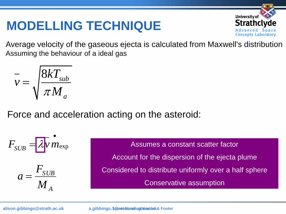
Force and acceleration acting on the asteroid:
expSUBF vm
MODELLING TECHNIQUE
Average velocity of the gaseous ejecta is calculated from Maxwell's distribution Assuming the behaviour of a ideal gas
Assumes a constant scatter factor
Account for the dispersion of the ejecta plume
Considered to distribute uniformly over a half sphere
Conservative assumption
Page 19
[email protected] @strath.ac.uk [email protected]
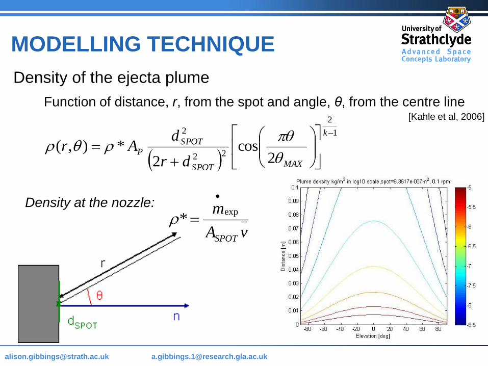
Density of the ejecta plume
Function of distance, r, from the spot and angle, θ, from the centre line
1
2
22
2
2cos
2*),(
k
MAXSPOT
SPOTP
dr
dAr
MODELLING TECHNIQUE
[Kahle et al, 2006]
exp*
SPOT
m
A v
Density at the nozzle:
Page 20
[email protected] @strath.ac.uk [email protected] Name as Header & Footer
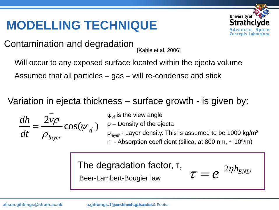
Contamination and degradation
Will occur to any exposed surface located within the ejecta volume
Assumed that all particles – gas – will re-condense and stick
)cos(2
vf
layer
v
dt
dh
MODELLING TECHNIQUE
Variation in ejecta thickness – surface growth - is given by:
2 ENDhe
Beer-Lambert-Bougier law
The degradation factor, τ,
[Kahle et al, 2006]
ψvf is the view angle
ρ – Density of the ejecta
ρlayer - Layer density. This is assumed to be 1000 kg/m3
η - Absorption coefficient (silica, at 800 nm, ~ 106/m)
Page 21
[email protected] @strath.ac.uk [email protected]
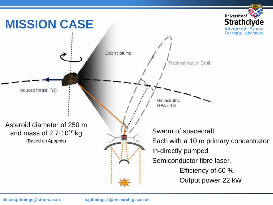
MISSION CASE
Asteroid diameter of 250 m
and mass of 2.7·1010 kg(Based on Apophis)
Swarm of spacecraft
Each with a 10 m primary concentrator
In-directly pumped
Semiconductor fibre laser,
Efficiency of 60 %
Output power 22 kW
Page 22
[email protected] @strath.ac.uk [email protected]
MISSION CASE Not accounting for degradation
Under ideal conditions
achieve a maximum
deflection distance of
30,000 km
Page 23
[email protected] @strath.ac.uk [email protected]
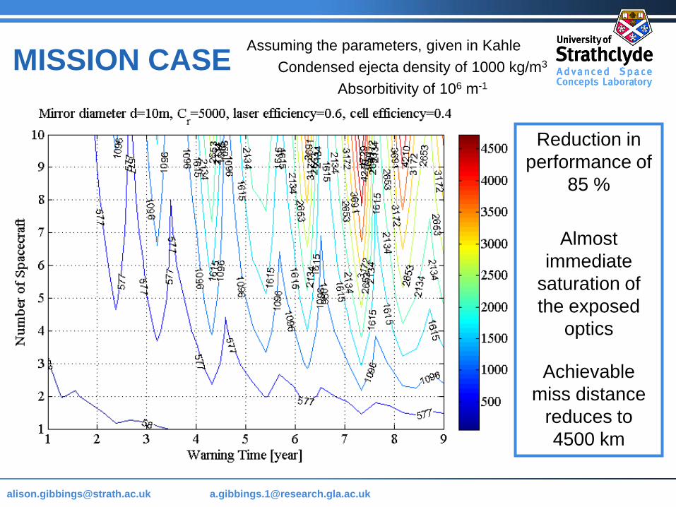
MISSION CASE Assuming the parameters, given in Kahle
Condensed ejecta density of 1000 kg/m3
Absorbitivity of 106 m-1
Reduction in
performance of
85 %
Almost
immediate
saturation of
the exposed
optics
Achievable
miss distance
reduces to
4500 km
Page 24
[email protected] @strath.ac.uk [email protected]
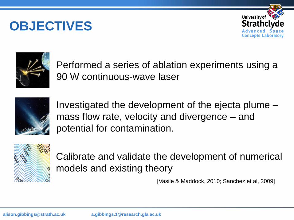
OBJECTIVES
[Vasile & Maddock, 2010; Sanchez et al, 2009]
Performed a series of ablation experiments using a
90 W continuous-wave laser
Investigated the development of the ejecta plume –
mass flow rate, velocity and divergence – and
potential for contamination.
Calibrate and validate the development of numerical
models and existing theory
Page 25
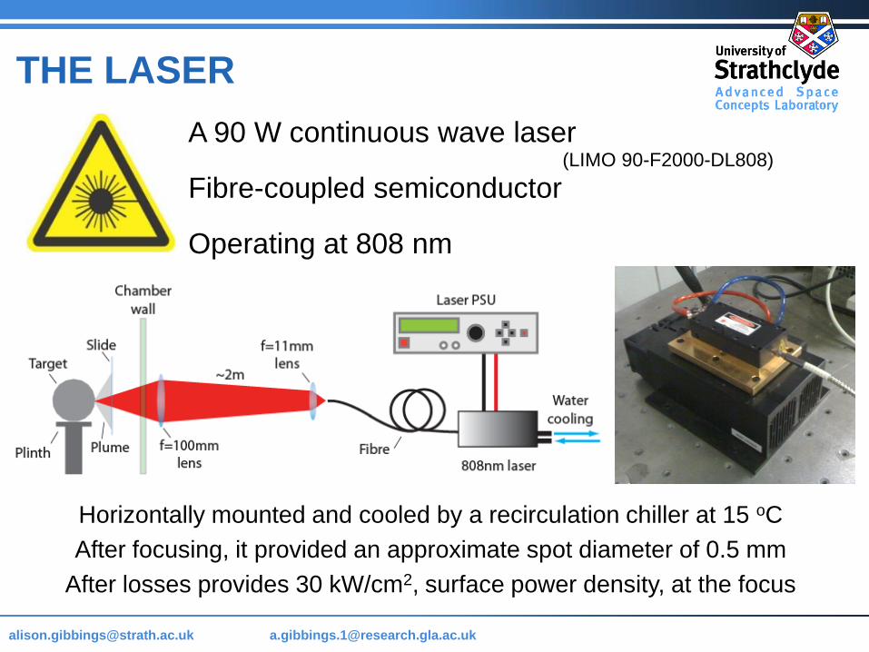
[email protected] @strath.ac.uk [email protected]
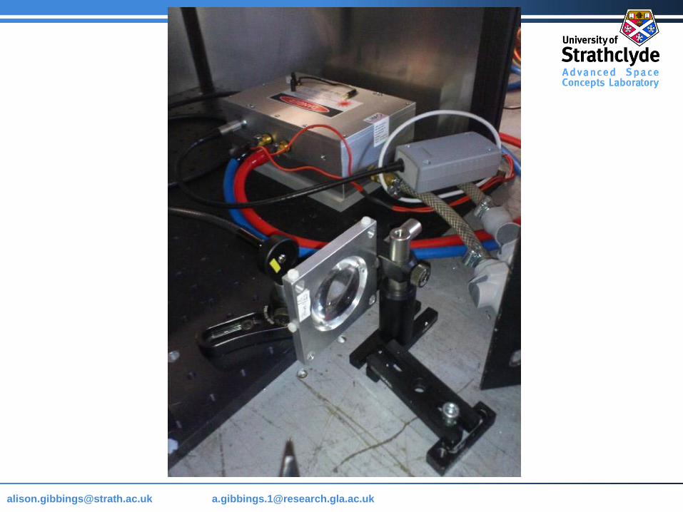
A 90 W continuous wave laser
Fibre-coupled semiconductor
Operating at 808 nm
THE LASER
(LIMO 90-F2000-DL808)
Horizontally mounted and cooled by a recirculation chiller at 15 oC
After focusing, it provided an approximate spot diameter of 0.5 mm
After losses provides 30 kW/cm2, surface power density, at the focus
Page 26
[email protected] @strath.ac.uk [email protected]
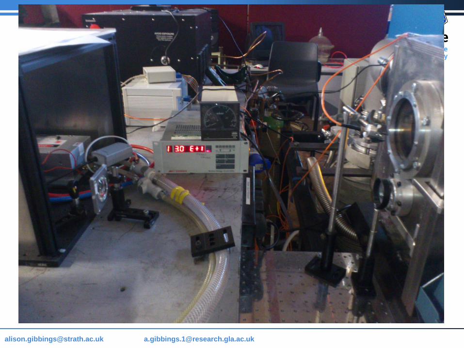
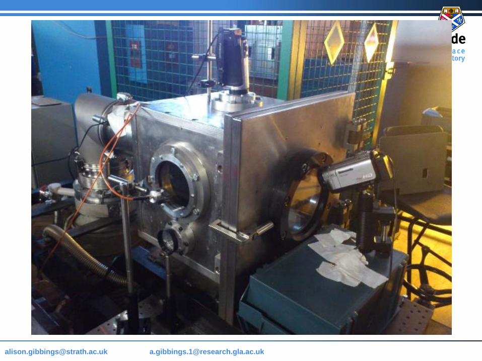
• Initial ablation experiments first occurred under a nitrogen
purge environment
• Transparent test chamber
• Reduce the occurrence of atmospheric combustion to negligible
levels. Any innate material combustion still occurred.
• Tested and refined the proposed methodologies and techniques
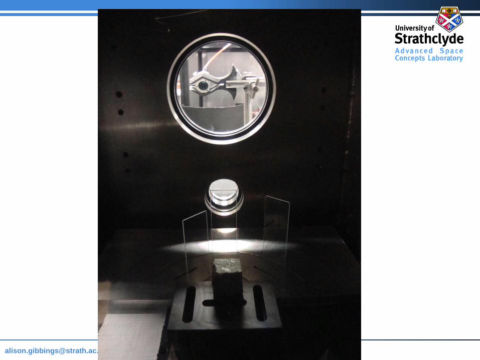
• Either measured, calculated or inferred quantities
• Developed and integrated the vacuum chamber system
• Allowed for maximum expansion of the plume
• Eliminating particle drag caused by an atmosphere
EXPERIMENT SEQUENCE
Page 27
[email protected] @strath.ac.uk [email protected]
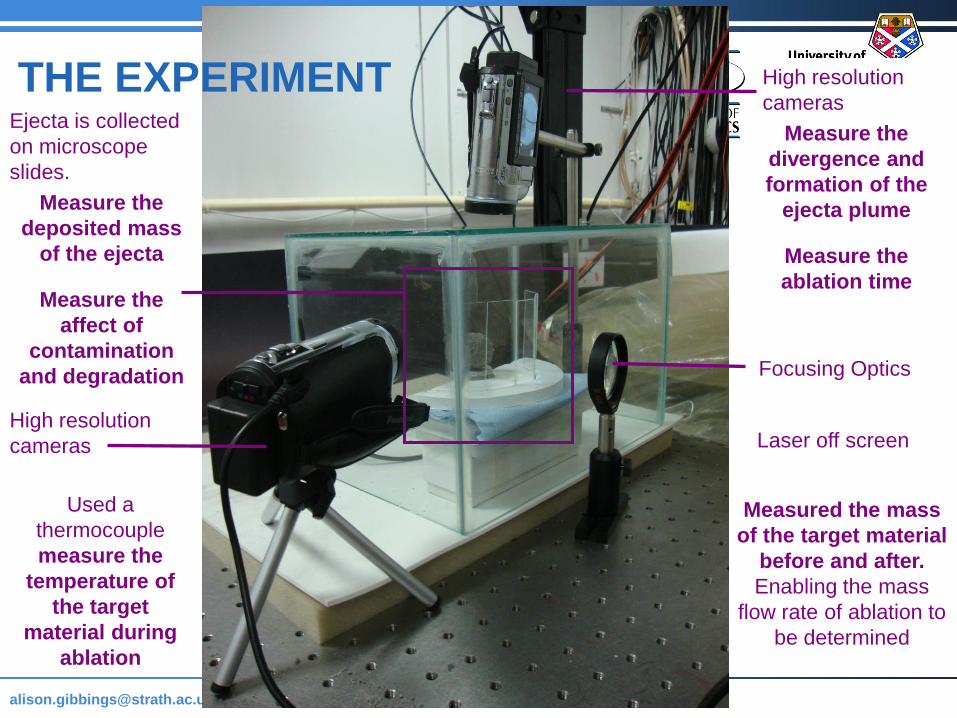
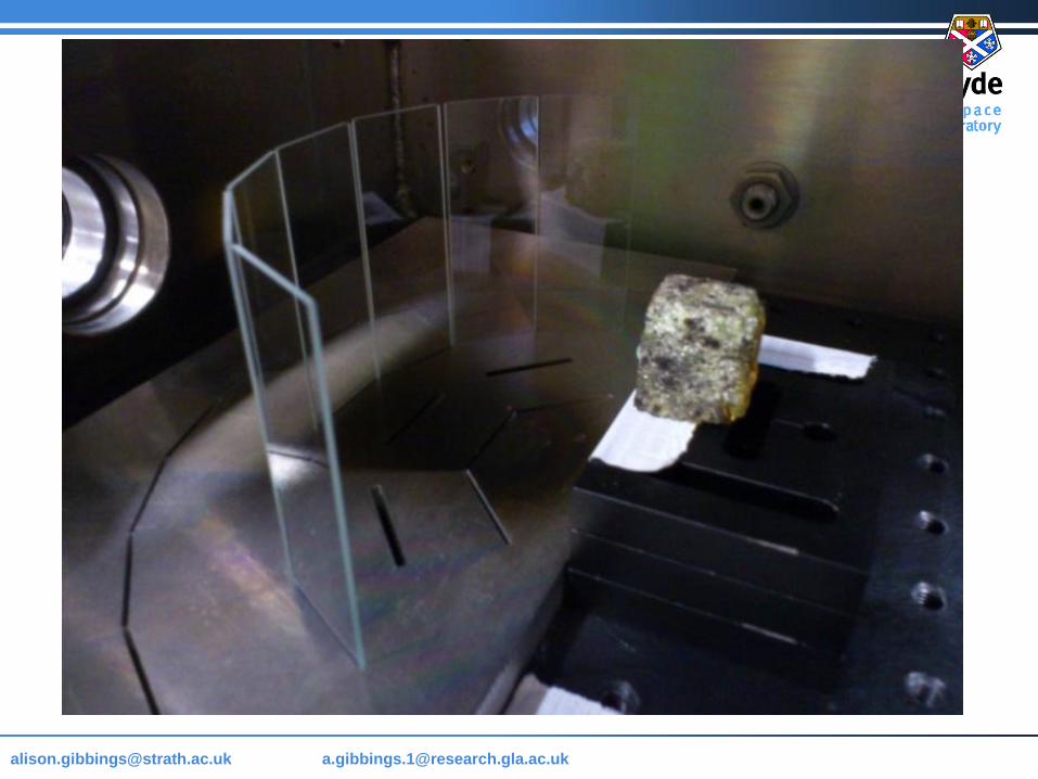
Focusing Optics
High resolution
cameras
Measure the
divergence and
formation of the
ejecta plume
Measure the
ablation time
Laser off screen
Ejecta is collected
on microscope
slides.
Measure the
deposited mass
of the ejecta
Measure the
affect of
contamination
and degradation
Measured the mass
of the target material
before and after.
Enabling the mass
flow rate of ablation to
be determined
Used a
thermocouple
measure the
temperature of
the target
material during
ablation
THE EXPERIMENT
High resolution
cameras
Page 28
[email protected] @strath.ac.uk [email protected]
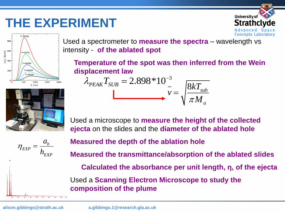
THE EXPERIMENT
Used a spectrometer to measure the spectra – wavelength vs
intensity - of the ablated spot
Temperature of the spot was then inferred from the Wein
displacement law
8 sub
a
kTv
M
32.898*10PEAK SUBT
Used a microscope to measure the height of the collected
ejecta on the slides and the diameter of the ablated hole
Measured the depth of the ablation hole
Measured the transmittance/absorption of the ablated slides
Calculated the absorbance per unit length, η, of the ejecta
Used a Scanning Electron Microscope to study the
composition of the plume
bEXP
EXP
a
h
Page 34
[email protected] @strath.ac.uk [email protected]
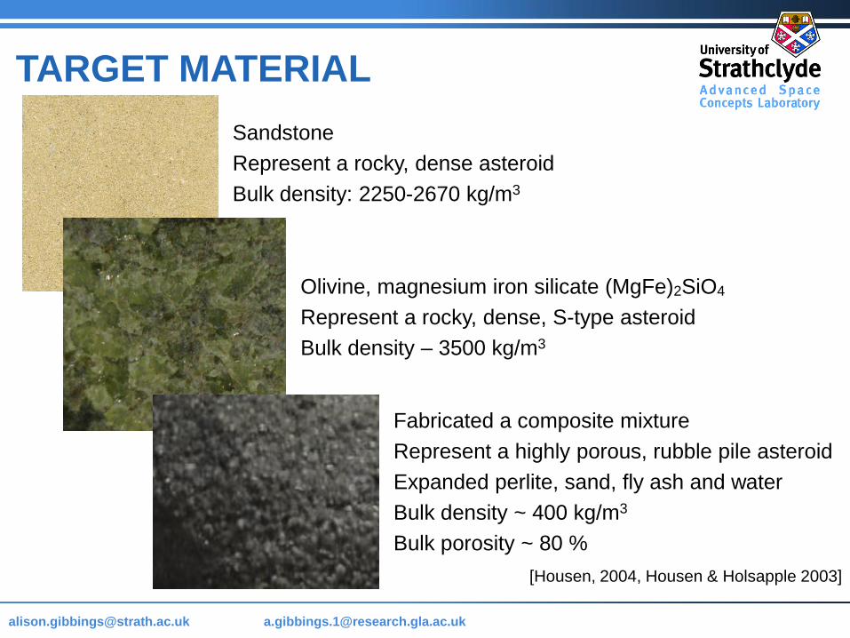
Sandstone
Represent a rocky, dense asteroid
Bulk density: 2250-2670 kg/m3
Fabricated a composite mixture
Represent a highly porous, rubble pile asteroid
Expanded perlite, sand, fly ash and water
Bulk density ~ 400 kg/m3
Bulk porosity ~ 80 %
TARGET MATERIAL
[Housen, 2004, Housen & Holsapple 2003]
Olivine, magnesium iron silicate (MgFe)2SiO4
Represent a rocky, dense, S-type asteroid
Bulk density – 3500 kg/m3
Page 35
[email protected] @strath.ac.uk [email protected]
NITROGEN PURGE
Small, and extended rocket plume
Similar mass flow rate, compared to the model
Variation in cone angle and ejecta distribution
Ablation process included solid ejecta particles
Subjected to the volumetric removal of material
Resulted in the laser tunnelling into the subsurface
Technique is sensitive to the focal point of the laser
T0 ~ 0.5 sec T ~ 1 min 14 sec
Subjected to the
structure and
composition of the
target material
Page 36
[email protected] @strath.ac.uk [email protected]
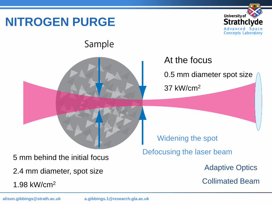
At the focus
0.5 mm diameter spot size
37 kW/cm2
5 mm behind the initial focus
2.4 mm diameter, spot size
1.98 kW/cm2
Widening the spot
Defocusing the laser beam
Adaptive Optics
Collimated Beam
NITROGEN PURGE
Page 37
[email protected] @strath.ac.uk [email protected]
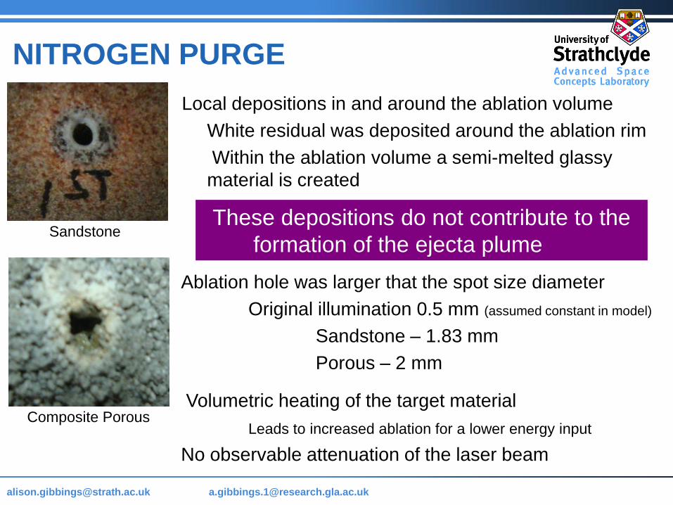
Ablation hole was larger that the spot size diameter
Original illumination 0.5 mm (assumed constant in model)
Sandstone – 1.83 mm
Porous – 2 mm
Volumetric heating of the target material
Leads to increased ablation for a lower energy input
No observable attenuation of the laser beam
These depositions do not contribute to the
formation of the ejecta plumeSandstone
Composite Porous
Local depositions in and around the ablation volume
White residual was deposited around the ablation rim
Within the ablation volume a semi-melted glassy
material is created
NITROGEN PURGE
Page 38
[email protected] @strath.ac.uk [email protected]
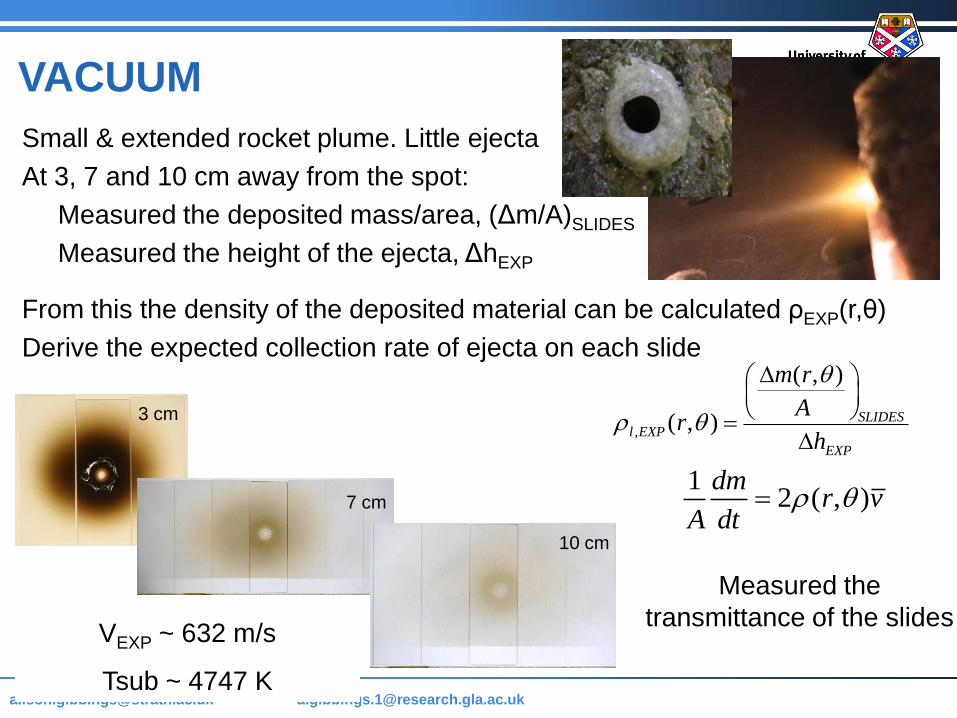
VACUUM
Small & extended rocket plume. Little ejecta
At 3, 7 and 10 cm away from the spot:
Measured the deposited mass/area, (Δm/A)SLIDES
Measured the height of the ejecta, ΔhEXP
From this the density of the deposited material can be calculated ρEXP(r,θ)
Derive the expected collection rate of ejecta on each slide
,
( , )
( , ) SLIDESl EXP
EXP
m r
Ar
h
12 ( , )
dmr v
A dt
Measured the
transmittance of the slides VEXP ~ 632 m/s
Tsub ~ 4747 K
3 cm
7 cm
10 cm
Page 39
[email protected] @strath.ac.uk [email protected]
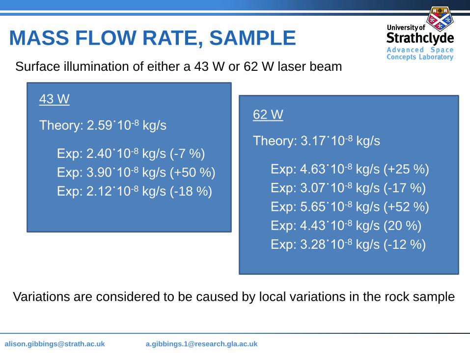
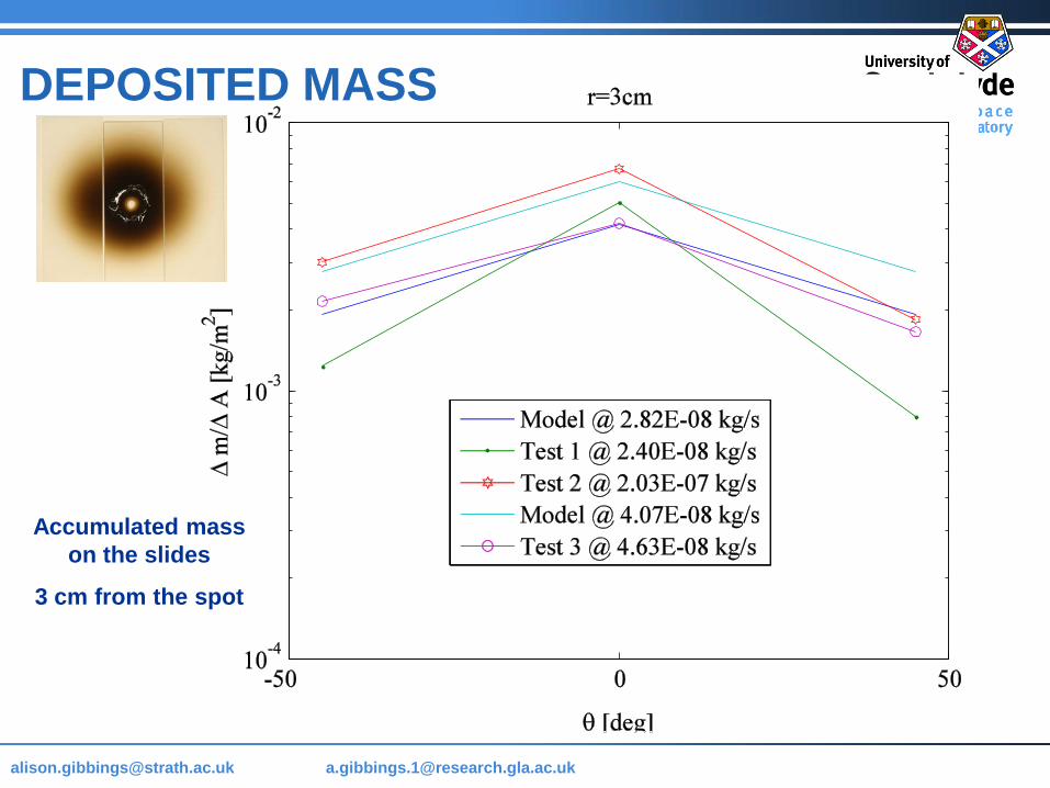
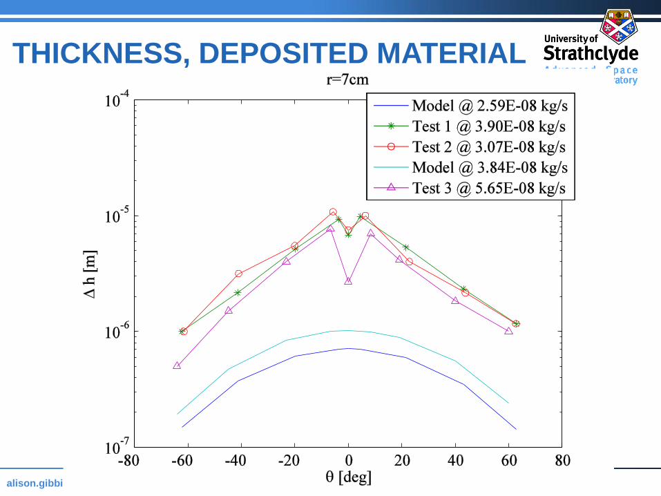
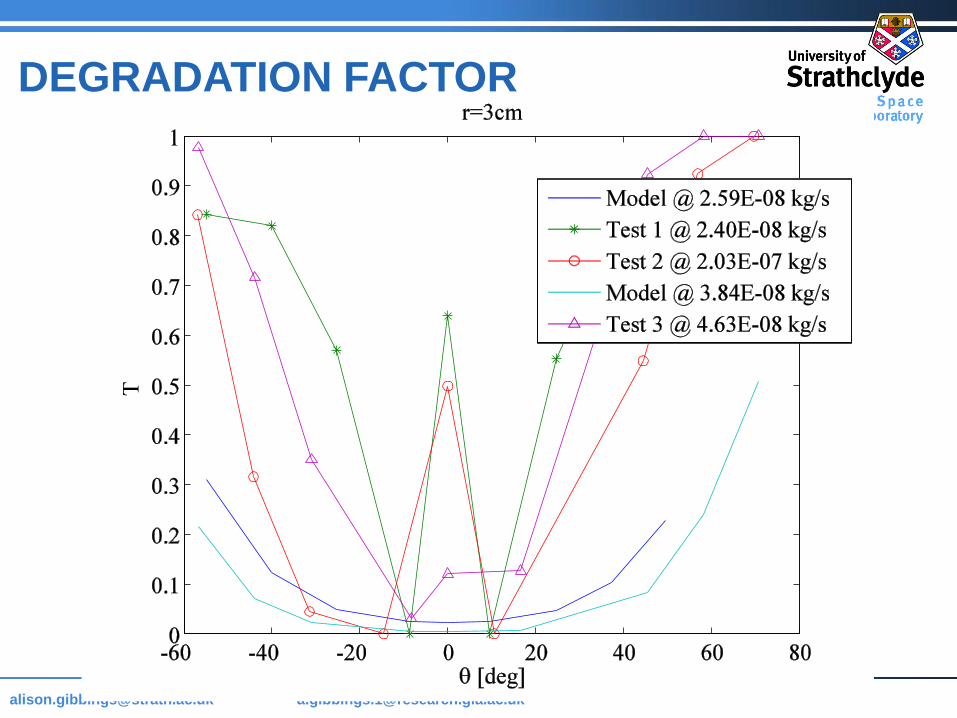
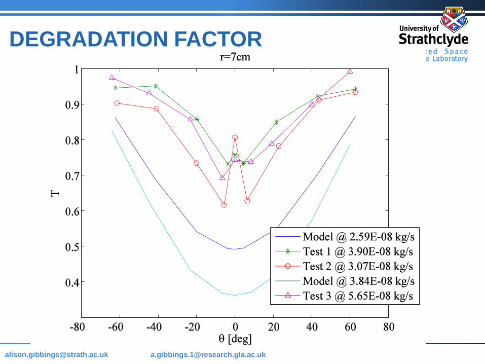
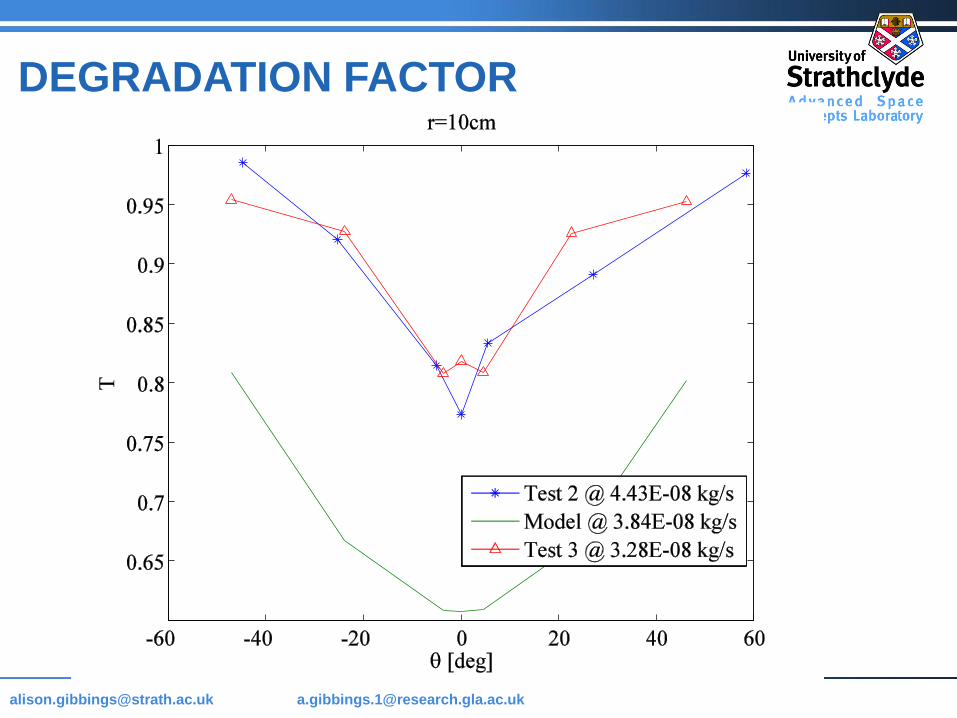
MASS FLOW RATE, SAMPLE
Surface illumination of either a 43 W or 62 W laser beam
43 W
Theory: 2.59˙10-8 kg/s
Exp: 2.40˙10-8 kg/s (-7 %)
Exp: 3.90˙10-8 kg/s (+50 %)
Exp: 2.12˙10-8 kg/s (-18 %)
Variations are considered to be caused by local variations in the rock sample
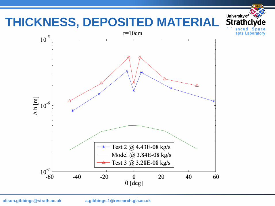
62 W
Theory: 3.17˙10-8 kg/s
Exp: 4.63˙10-8 kg/s (+25 %)
Exp: 3.07˙10-8 kg/s (-17 %)
Exp: 5.65˙10-8 kg/s (+52 %)
Exp: 4.43˙10-8 kg/s (20 %)
Exp: 3.28˙10-8 kg/s (-12 %)
Page 40
[email protected] @strath.ac.uk [email protected]
DEPOSITED MASS
Accumulated mass
on the slides
3 cm from the spot
Page 41
[email protected] @strath.ac.uk [email protected]
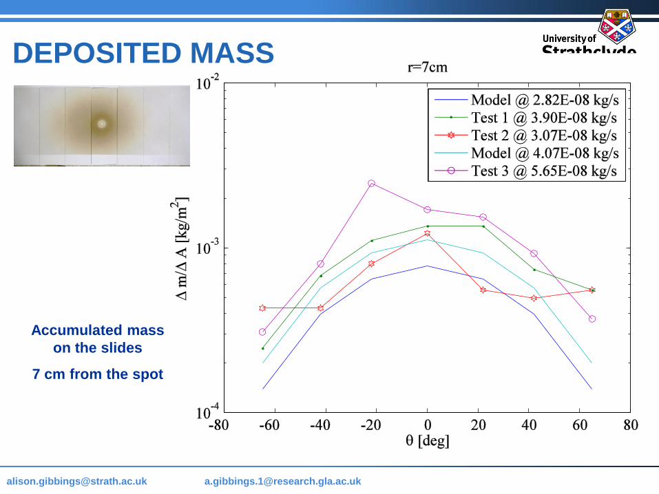
Accumulated mass
on the slides
7 cm from the spot
DEPOSITED MASS
Page 42
[email protected] @strath.ac.uk [email protected]
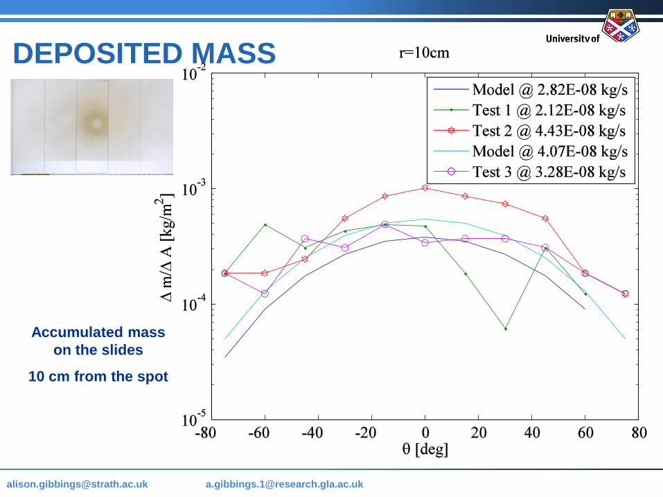
Accumulated mass
on the slides
10 cm from the spot
DEPOSITED MASS
Page 43
[email protected] @strath.ac.uk [email protected]
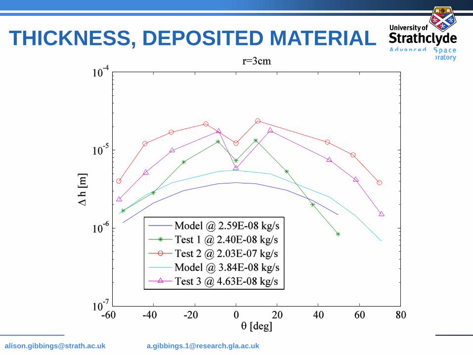
THICKNESS, DEPOSITED MATERIAL
Page 44
[email protected] @strath.ac.uk [email protected]
THICKNESS, DEPOSITED MATERIAL
Page 45
[email protected] @strath.ac.uk [email protected]
THICKNESS, DEPOSITED MATERIAL
Page 46
[email protected] @strath.ac.uk [email protected]
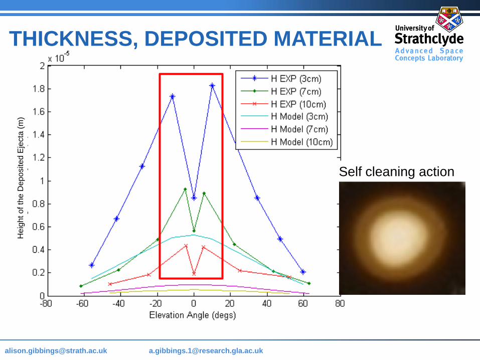
Self cleaning action
THICKNESS, DEPOSITED MATERIAL H
eig
ht o
f th
e D
ep
osite
d E
jecta
(m
)
Page 47
[email protected] @strath.ac.uk [email protected]
0
0.1
0.2
0.3
0.4
0.5
0.6
0.7
0.8
0.9
1
0 100 200 300 400 500 600 700
Distance across (pixel)
Tra
nsm
itta
nce
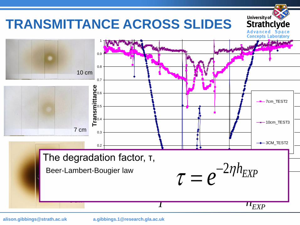
7cm_TEST2
10cm_TEST3
3CM_TEST2
TRANSMITTANCE ACROSS SLIDES
1logba
T
bEXP
EXP
a
h
3 cm
The degradation factor, τ,
2 EXPhe Beer-Lambert-Bougier law
7 cm
10 cm
Page 48
[email protected] @strath.ac.uk [email protected]
DEGRADATION FACTOR
Page 49
[email protected] @strath.ac.uk [email protected]
DEGRADATION FACTOR
Page 50
[email protected] @strath.ac.uk [email protected]
DEGRADATION FACTOR
Page 51
[email protected] @strath.ac.uk [email protected]
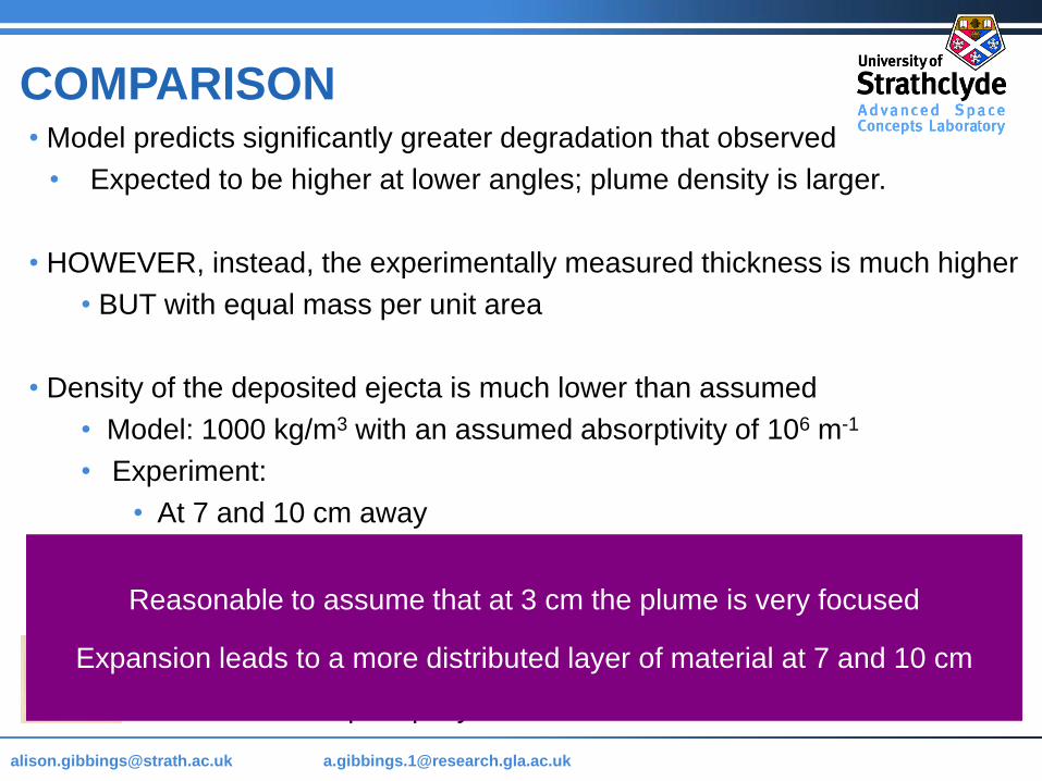
• Model predicts significantly greater degradation that observed
• Expected to be higher at lower angles; plume density is larger.
• HOWEVER, instead, the experimentally measured thickness is much higher
• BUT with equal mass per unit area
• Density of the deposited ejecta is much lower than assumed
• Model: 1000 kg/m3 with an assumed absorptivity of 106 m-1
• Experiment:
• At 7 and 10 cm away
• Deposited density is 250 kg/m3 and an absorptivity of 5·104 m-1
• At 3 cm, on the central slide:
• Deposited density 700 kg/m3 absorptivity of 105 m-1,
• But drops rapidly below 104 m-1 over the slides at +/- 45°
COMPARISON
Reasonable to assume that at 3 cm the plume is very focused
Expansion leads to a more distributed layer of material at 7 and 10 cm
Page 52
[email protected] @strath.ac.uk [email protected]
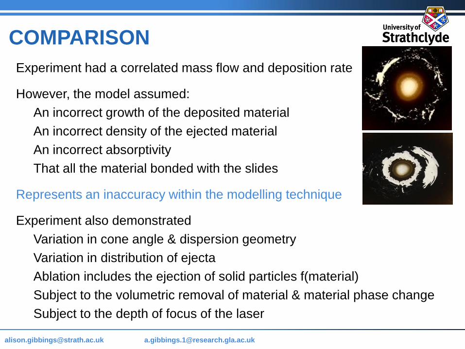
Experiment had a correlated mass flow and deposition rate
However, the model assumed:
An incorrect growth of the deposited material
An incorrect density of the ejected material
An incorrect absorptivity
That all the material bonded with the slides
Represents an inaccuracy within the modelling technique
Experiment also demonstrated
Variation in cone angle & dispersion geometry
Variation in distribution of ejecta
Ablation includes the ejection of solid particles f(material)
Subject to the volumetric removal of material & material phase change
Subject to the depth of focus of the laser
COMPARISON
Page 53
[email protected] @strath.ac.uk [email protected]
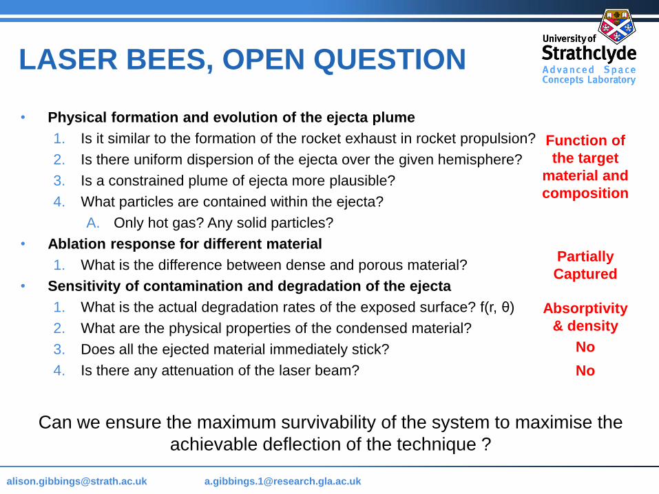
LASER BEES, OPEN QUESTION
• Physical formation and evolution of the ejecta plume
1. Is it similar to the formation of the rocket exhaust in rocket propulsion?
2. Is there uniform dispersion of the ejecta over the given hemisphere?
3. Is a constrained plume of ejecta more plausible?
4. What particles are contained within the ejecta?
A. Only hot gas? Any solid particles?
• Ablation response for different material
1. What is the difference between dense and porous material?
• Sensitivity of contamination and degradation of the ejecta
1. What is the actual degradation rates of the exposed surface? f(r, θ)
2. What are the physical properties of the condensed material?
3. Does all the ejected material immediately stick?
4. Is there any attenuation of the laser beam?
Can we ensure the maximum survivability of the system to maximise the
achievable deflection of the technique ?
Function of
the target
material and
composition
Partially
Captured
Absorptivity
& density
No
No
Page 54
[email protected] @strath.ac.uk [email protected]
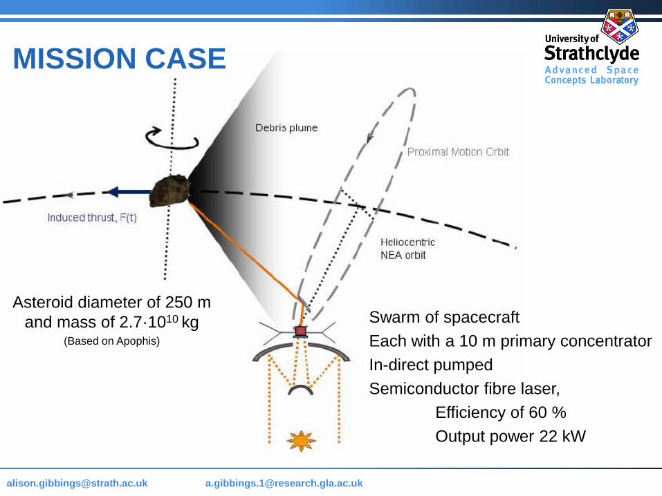
MISSION CASE
Asteroid diameter of 250 m
and mass of 2.7·1010 kg(Based on Apophis)
Swarm of spacecraft
Each with a 10 m primary concentrator
In-direct pumped
Semiconductor fibre laser,
Efficiency of 60 %
Output power 22 kW
Page 55
[email protected] @strath.ac.uk [email protected]
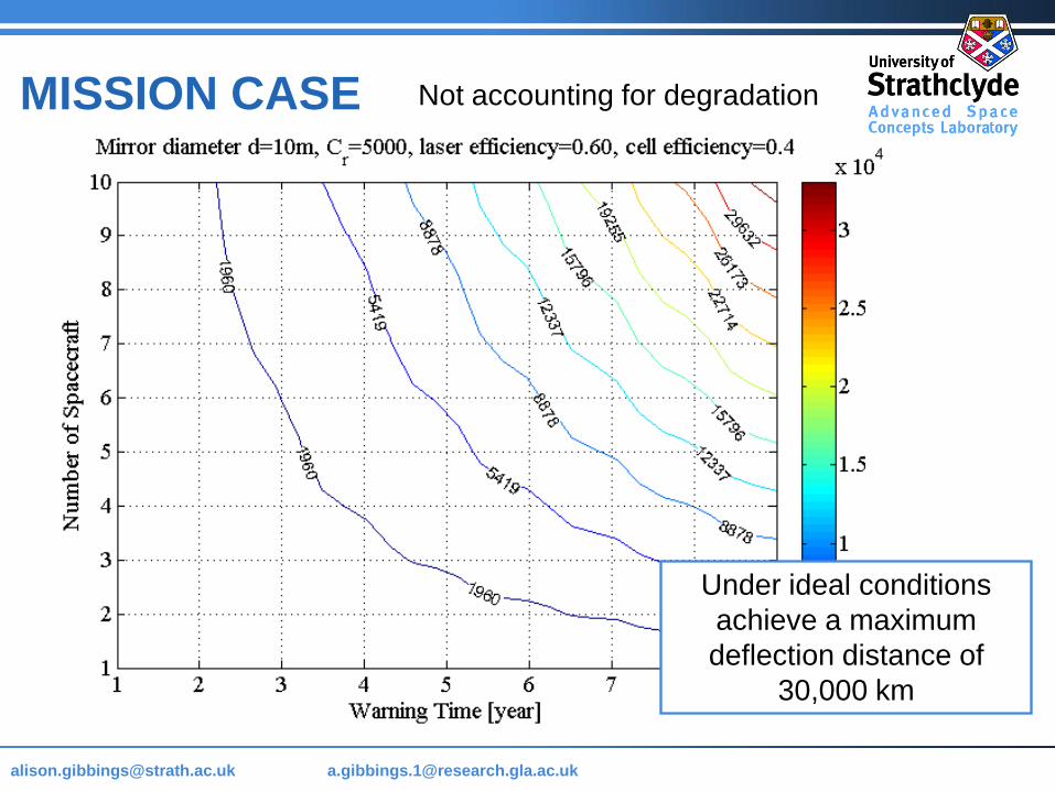
MISSION CASE Not accounting for degradation
Under ideal conditions
achieve a maximum
deflection distance of
30,000 km
Page 56
[email protected] @strath.ac.uk [email protected]
MISSION CASE Assuming the parameters, given in Kahle
Condensed ejecta density of 1000 kg/m3
Absorbitivity of 106 m-1
Reduction in
performance of
85 %
Almost
immediate
saturation of
the exposed
optics
Achievable
miss distance
reduces to
4500 km
Page 57
[email protected] @strath.ac.uk [email protected]
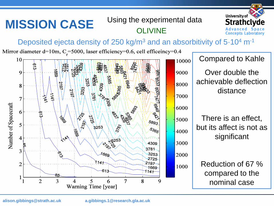
MISSION CASE Using the experimental data
OLIVINE
Deposited ejecta density of 250 kg/m3 and an absorbitivity of 5·104 m-1
Compared to Kahle
Over double the
achievable deflection
distance
There is an effect,
but its affect is not as
significant
Reduction of 67 %
compared to the
nominal case
Page 58
[email protected] @strath.ac.uk [email protected]
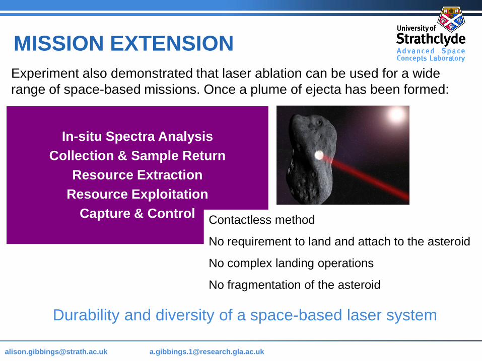
Experiment also demonstrated that laser ablation can be used for a wide
range of space-based missions. Once a plume of ejecta has been formed:
MISSION EXTENSION
In-situ Spectra Analysis
Collection & Sample Return
Resource Extraction
Resource Exploitation
Capture & ControlContactless method
No requirement to land and attach to the asteroid
No complex landing operations
No fragmentation of the asteroid
Durability and diversity of a space-based laser system
Page 59
[email protected] @strath.ac.uk [email protected]
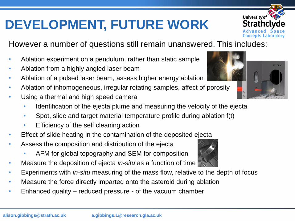
However a number of questions still remain unanswered. This includes:
• Ablation experiment on a pendulum, rather than static sample
• Ablation from a highly angled laser beam
• Ablation of a pulsed laser beam, assess higher energy ablation
• Ablation of inhomogeneous, irregular rotating samples, affect of porosity
• Using a thermal and high speed camera
• Identification of the ejecta plume and measuring the velocity of the ejecta
• Spot, slide and target material temperature profile during ablation f(t)
• Efficiency of the self cleaning action
• Effect of slide heating in the contamination of the deposited ejecta
• Assess the composition and distribution of the ejecta
• AFM for global topography and SEM for composition
• Measure the deposition of ejecta in-situ as a function of time
• Experiments with in-situ measuring of the mass flow, relative to the depth of focus
• Measure the force directly imparted onto the asteroid during ablation
• Enhanced quality – reduced pressure - of the vacuum chamber
DEVELOPMENT, FUTURE WORK
Page 60
[email protected] @strath.ac.uk [email protected]
Thank you for your time & the continued support of The Planetary Society.
Questions Please
Page 61
[email protected] @strath.ac.uk [email protected]
References Conway, B.A “Near-optimal deflection of Earth-approaching asteroids”. J.Guidance, Control and Dynamics 24
(5), 1035–1037, 2001
Gritzner, C., Kahle, RMitigation technologies and their requirements, in: Belton, M.,Morgan, T., Samarainha,
N., Yeomans, D. (Eds.), Mitigation of Hazardous Comets and Asteroid. Cambridge University Press,
Cambridge, pp. 167–200, 2004
Housen “Collisional Fragmentation of Rotating Bodies”, Lunar and Planetary Science XXXV, No 1826, 2004
Housen K.R, Holsapple K “Impact Cratering On Porous Asteroids”. Academic Press, Icarus 163. Pg 102-119,
2003
Kahle R, Kuhrt E, Hahn G, Knolenberg J “Physical Limits of Solar Collectors in Deflecting Earth-threatening
Asteroids” Advanced Science and Technology, Vol 10, pg 256-263, 2006
Melosh, H.J., Nemchinov, I.V., Zetzer, Y.I. Non-nuclear strategies for deflecting comets and asteroids, in:
Gehrels, T. (Ed.), Hazards due to Comets and Asteroids. University of Arizona Press, Tucson, AZ, pp. 1111–
1132, 1994
Phipps C, Birkan M, Bohn W et al “Review: Laser Ablation Propulsion”, Journal of Propulsion and Power, Vol
26, No 4, 2010
Sanchez, J.P., Colombo, C., Vasile, M., et al “Multicriteria comparison among several mitigation strategies for
dangerous Near-Earth objects”. J. Guid. Control Dynam. 32, 121–141, 2009.
Vasile M, Maddock C “On the Deflection of Asteroids with Mirrors”, Journal Celestial Mechanical Dynamics,
Vol 107, pg 265-284, 2010
Vasile M., Maddock C., Radice G., McInnes C “NEO Deflection though a Multi-Mirror System”, ESA Call for
Proposals: Encounter 2029, Final Report for Ariadna Study Contract 08/4301, Technical officer: Summerer L.,
March 2009.
Alvarz L et al, Extraterrestrial Cuase for the Cretaceous-Tertiary Extinction, Science 6, Vol 208, no 4448, 1980
Page 62
[email protected] @strath.ac.uk [email protected]
BACK-UP MATERIAL
Page 63
[email protected] @strath.ac.uk [email protected]
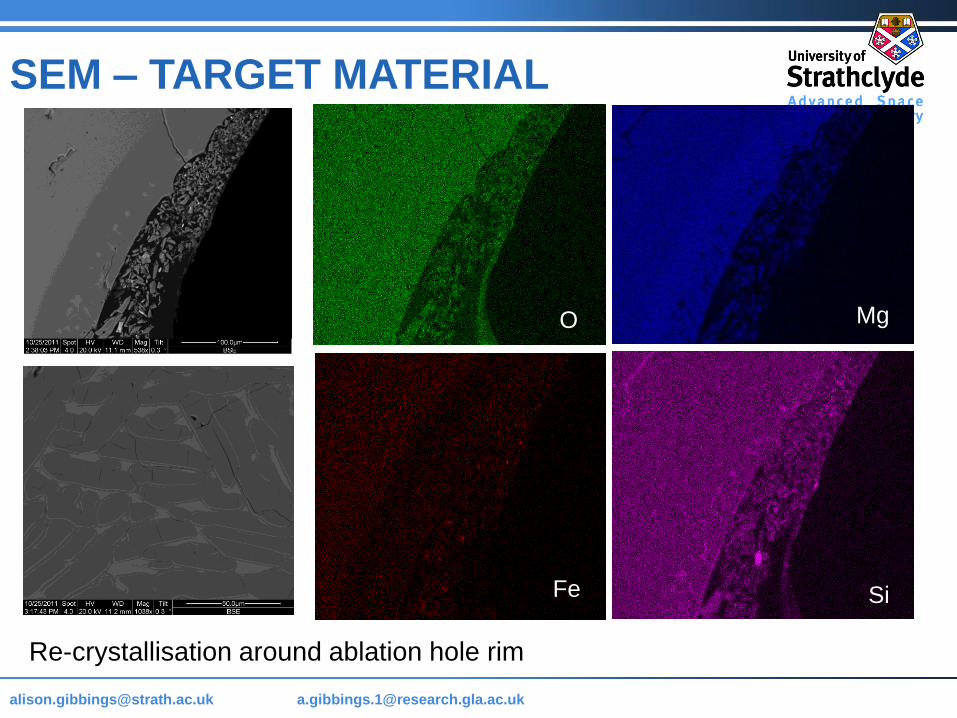
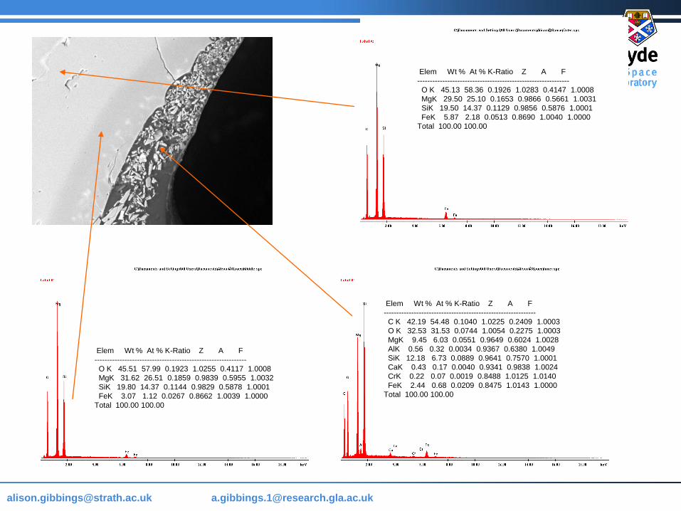
SEM – TARGET MATERIAL
O Mg
SiFe
Re-crystallisation around ablation hole rim
Page 64
[email protected] @strath.ac.uk [email protected]
Elem Wt % At % K-Ratio Z A F
-------------------------------------------------------------
O K 45.13 58.36 0.1926 1.0283 0.4147 1.0008
MgK 29.50 25.10 0.1653 0.9866 0.5661 1.0031
SiK 19.50 14.37 0.1129 0.9856 0.5876 1.0001
FeK 5.87 2.18 0.0513 0.8690 1.0040 1.0000
Total 100.00 100.00
Elem Wt % At % K-Ratio Z A F
-------------------------------------------------------------
O K 45.51 57.99 0.1923 1.0255 0.4117 1.0008
MgK 31.62 26.51 0.1859 0.9839 0.5955 1.0032
SiK 19.80 14.37 0.1144 0.9829 0.5878 1.0001
FeK 3.07 1.12 0.0267 0.8662 1.0039 1.0000
Total 100.00 100.00
Elem Wt % At % K-Ratio Z A F
-------------------------------------------------------------
C K 42.19 54.48 0.1040 1.0225 0.2409 1.0003
O K 32.53 31.53 0.0744 1.0054 0.2275 1.0003
MgK 9.45 6.03 0.0551 0.9649 0.6024 1.0028
AlK 0.56 0.32 0.0034 0.9367 0.6380 1.0049
SiK 12.18 6.73 0.0889 0.9641 0.7570 1.0001
CaK 0.43 0.17 0.0040 0.9341 0.9838 1.0024
CrK 0.22 0.07 0.0019 0.8488 1.0125 1.0140
FeK 2.44 0.68 0.0209 0.8475 1.0143 1.0000
Total 100.00 100.00
Page 65
[email protected] @strath.ac.uk [email protected]
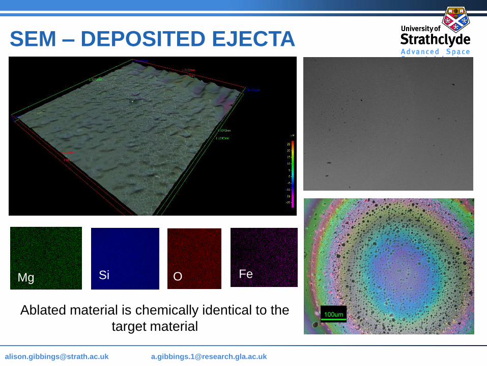
SEM – DEPOSITED EJECTA
FeMg OSi
Ablated material is chemically identical to the
target material
Page 66
[email protected] @strath.ac.uk [email protected]
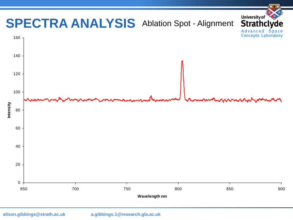
0
20
40
60
80
100
120
140
160
650 700 750 800 850 900
Wavelength nm
Inte
ns
ity
SPECTRA ANALYSIS Ablation Spot - Alignment
Page 67
[email protected] @strath.ac.uk [email protected]
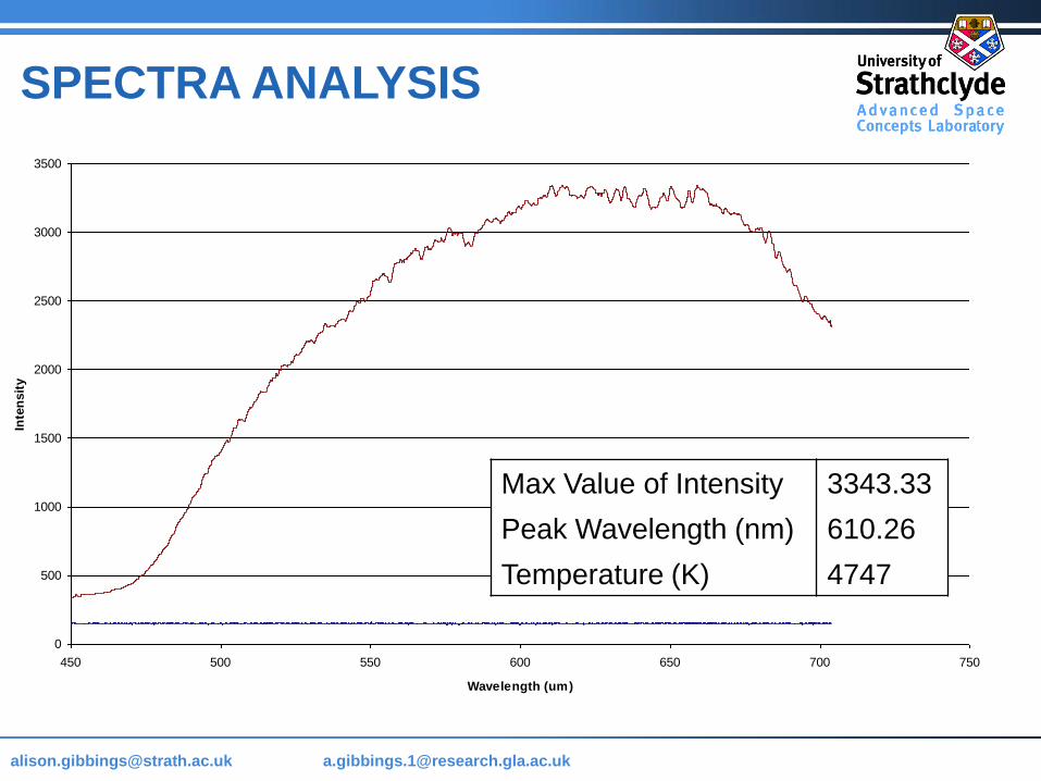
0
500
1000
1500
2000
2500
3000
3500
450 500 550 600 650 700 750
Wavelength (um)
Inte
nsit
y
Max Value of Intensity 3343.33
Peak Wavelength (nm) 610.26
Temperature (K) 4747
SPECTRA ANALYSIS
Page 68
[email protected] @strath.ac.uk [email protected] Name as Header & Footer 68
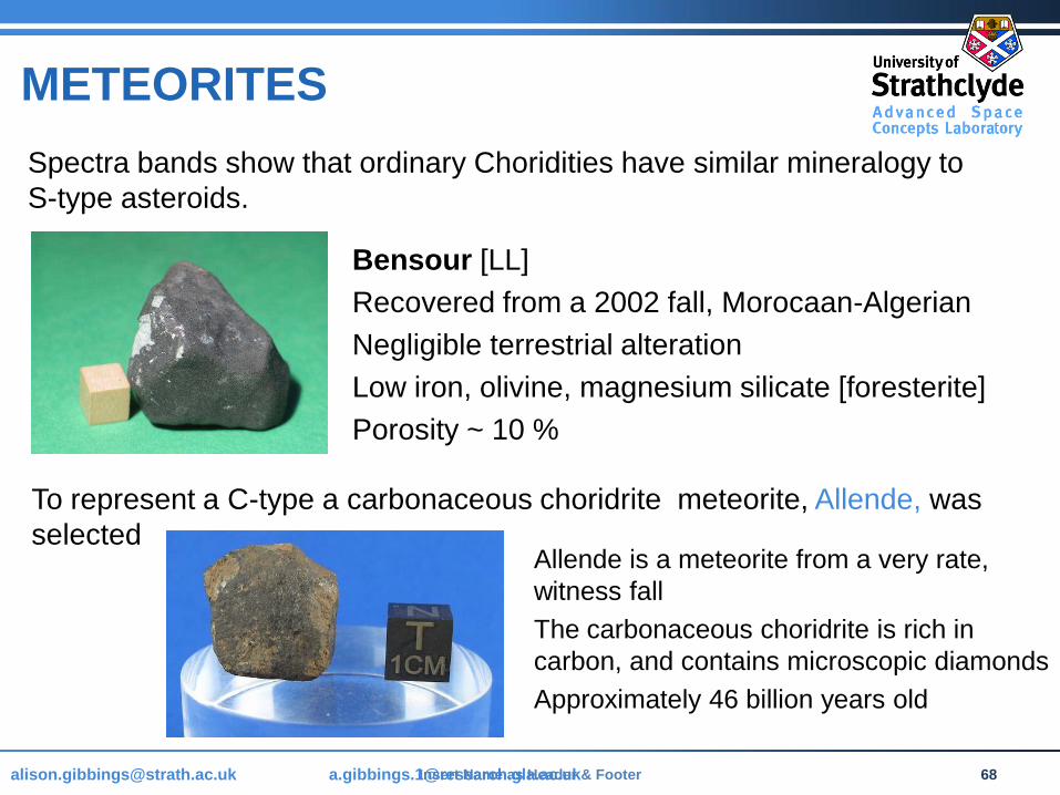
Spectra bands show that ordinary Choridities have similar mineralogy to
S-type asteroids.
Bensour [LL]
Recovered from a 2002 fall, Morocaan-Algerian
Negligible terrestrial alteration
Low iron, olivine, magnesium silicate [foresterite]
Porosity ~ 10 %
To represent a C-type a carbonaceous choridrite meteorite, Allende, was
selectedAllende is a meteorite from a very rate,
witness fall
The carbonaceous choridrite is rich in
carbon, and contains microscopic diamonds
Approximately 46 billion years old
METEORITES
Page 69
[email protected] @strath.ac.uk [email protected]
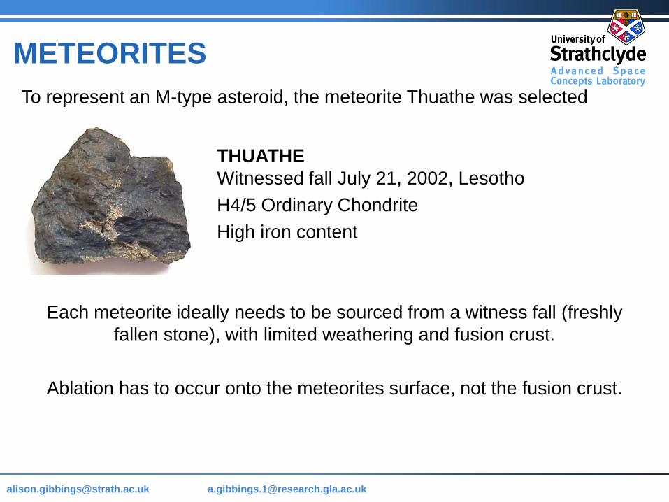
THUATHE
Witnessed fall July 21, 2002, Lesotho
H4/5 Ordinary Chondrite
High iron content
To represent an M-type asteroid, the meteorite Thuathe was selected
Each meteorite ideally needs to be sourced from a witness fall (freshly
fallen stone), with limited weathering and fusion crust.
Ablation has to occur onto the meteorites surface, not the fusion crust.
METEORITES