72
LBI-39209 ericssonzy Maintenance Manual Integrated EDACS ® Alarm (IEA) System Introduction/Operation/Configuration

LBI-39209
ericssonzy
Maintenance Manual
Integrated EDACS® Alarm(IEA) SystemIntroduction/Operation/Configuratio n

LBI-39209
2
TABLE OF CONTENTS
Page
IMPORTANT SAFETY INFORMATION................................................................................................................................4
INTRODUCTION......................................................................................................................................................................5
SYSTEM ARCHITECTURE.....................................................................................................................................................5
EXTERNAL INTERFACES......................................................................................................................................................5Graphic User Interface (GUI) ..................................................................................................................................................5Event Log Interface..................................................................................................................................................................5Printer Interface .......................................................................................................................................................................5Site Controller Interface...........................................................................................................................................................5GETC Interface........................................................................................................................................................................5Digital Input Interface..............................................................................................................................................................6Digital Output Interface ...........................................................................................................................................................7Analog Input Interface .............................................................................................................................................................7Orion Test Unit Interface .........................................................................................................................................................7Base Station Receiver Fault Interface ......................................................................................................................................8Push-To-Talk (PTT) Interface .................................................................................................................................................8GPS Receiver Interface............................................................................................................................................................8Intraplex Multiplexer Interface ................................................................................................................................................8MASTR III Base Station Interface...........................................................................................................................................8Control Point to Transmit Site Interface ..................................................................................................................................8Hardware User Interface ..........................................................................................................................................................8
NOTICE!
This manual covers Ericsson and General Electric products manufactured and sold by Ericsson Inc.
NOTICE!
Repairs to this equipment should be made only by an authorized service technician or facility designated by the supplier. Anyrepairs, alterations or substitution of recommended parts made by the user to this equipment not approved by the manufacturer couldvoid the user’s authority to operate the equipment in addition to the manufacturer’s warranty.
NOTICE!The software contained in this device is copyrighted by Ericsson Inc. Unpublished rights are reservedunder the copyright laws of the United States.
This manual is published by Ericsson Inc., without any warranty. Improvements and changes to this manual necessitated by typographical errors, inaccuracies of current information, or improvements to programs and/orequipment, may be made by Ericsson Inc., at any time and without notice. Such changes will be incorporated into new editions of this manual. No part of this manual may be reproduced or transmitted in any form or byany means, electronic or mechanical, including photocopying and recording, for any purpose, without the express written permission of Ericsson Inc.
Copyright August 1996, Ericsson Inc
LBI-39209
3
OPERATION..........................................................................................................................................................................9
ALARM SYSTEM START/STOP .........................................................................................................................................9Automatic On At Power Up..................................................................................................................................................9Manual Shut Down ...............................................................................................................................................................9Restart...................................................................................................................................................................................9Reboot...................................................................................................................................................................................9
MAIN MMI WINDOW ..........................................................................................................................................................9Pull Down Menus ...............................................................................................................................................................10Equipment Palette...............................................................................................................................................................12Tree View ...........................................................................................................................................................................13Map View ...........................................................................................................................................................................13Properties View ..................................................................................................................................................................14
USING THE SYSTEM.........................................................................................................................................................22Alarms ................................................................................................................................................................................22Latched Alarm Status..........................................................................................................................................................22Event Log ...........................................................................................................................................................................23RF Power ............................................................................................................................................................................24Site Links............................................................................................................................................................................27
CONFIGURATION..............................................................................................................................................................28
EXTENDED NETWORK ....................................................................................................................................................28
ADD A MULTISITE NETWORK .......................................................................................................................................30
EDACS SYSTEM.................................................................................................................................................................33
EDACS SITE ........................................................................................................................................................................35
ADDITION OF OTHER DEVICES .....................................................................................................................................37
ADD A CHANNEL ..............................................................................................................................................................37
ADD A GPS RECEIVER......................................................................................................Error! Bookmark not defined.
ADD A MULTIPLEXER......................................................................................................................................................43
ADD AN ANTENNA ...........................................................................................................................................................46
ADD A DIGITAL ALARM GROUP....................................................................................................................................48
ADD A DIGITAL INPUT ALARM .....................................................................................................................................51
APPENDICES
APPENDIX A - IEA INPUT/OUTPUT SIGNAL MAPPING..............................................................................................A1Digital Interrtupt Board Signals......................................................................................................................................A2Analog I/O Board Signals...............................................................................................................................................A4General Purpose I/O Digital (GPDIO) Baord Signals ....................................................................................................A6
APPENDIX B - COMMUNICATIONS PORT ....................................................................................................................B1Digital Interrupt Board ..................................................................................................................................................B2

LBI-39209 INTRODUCTION
4
IMPORTANT SAFETYINFORMATION
The following general safety precautions must beobserved during all phases of operation, service, andrepair of this product. Failure to comply with theseprecautions or with specific warnings elsewhere in thismanual violates safety standards of design, manufacture,and intended use of the product. Ericsson Inc. assumes noliability for the customer's failure to comply with thesestandards.
1. SAVE THIS MANUAL - It contains importantsafety and operating instructions.
2. Before using this equipment, please follow andadhere to all warnings, safety and operatinginstructions located on the product and in the manual.
3. DO NOT expose equipment to rain, snow or othertype of moisture.
4. Care should be taken so objects do not fall or liquidsdo not spill into the equipment.
5. DO NOT expose equipment to extreme temperatures.
6. DO NOT use auxiliary equipment not recommendedor sold by Ericsson. To do so may result in a risk offire, electric shock or injury to persons.
7 GROUND THE EQUIPMENT -To minimize shockhazard, the station equipment cabinet must beconnected to an electrical ground.
The equipment supplied is equipped with three-conductor AC power cords. These power cords mustbe plugged into approved three-contact electricaloutlets with the grounding wires firmly connected toan electrical ground (safety ground) at the poweroutlet. The power cords must also meet InternationalEnergy Commission (IEC) safety standards.
8. To reduce risk of damage to electrical cords, pull byplug rather than cord when disconnecting a unit.
9. Make sure all power cords are located so they will notbe stepped on, tripped over or otherwise subjected todamage or stress.
10. An extension cord should not be used unlessabsolutely necessary. Use of an improper extensioncord could result in a risk of fire and electric shock. Ifan extension cord must be used, ensure:
a. The pins on the plug of the extension cord arethe same number, size, and shape as those of theplug on the power supply.
b. The extension cord is properly wired, in goodcondition, and
c. The wire size is large enough for the ACampere rating of unit.
11. DO NOT operate equipment with damaged powercords or plugs - replace them immediately.
12. DO NOT operate this product in an explosiveatmosphere unless it has been specifically certifiedfor such operation.
13. To reduce risk of electric shock, unplug unit fromoutlet before attempting any maintenance or cleaning.
14. DO NOT operate this product with covers or panelsremoved. Refer all servicing to qualified servicepersonnel.
15. Use only fuses of the correct type, voltage rating andcurrent rating as specified in the parts list. Failure todo so can result in fire hazard.
16. GROUNDING AND AC POWER CORDCONNECTION - To reduce risk of electrical shockuse only a properly grounded outlet. The systemcomponents are equipped with electric cords havingan equipment grounding conductor and a groundingplug. Be sure all outlets are properly installed andgrounded in accordance with all local codes andordinances.
17. DANGER - Never alter the AC cord or plug. Pluginto an outlet properly wired by a qualifiedelectrician. Improper connection or loss of groundconnection can result in risk of an electrical shock.
18 ELECTROSTATIC DISCHARGE SENSITIVECOMPONENTS - This station contains CMOS andother circuit components which may be damaged byelectrostatic discharge. Proper precaution must betaken when handling circuit modules. As a minimum,grounded wrist straps should be used at all timeswhen handling circuit modules.
INTRODUCTION LBI-39209
5
INTRODUCTION
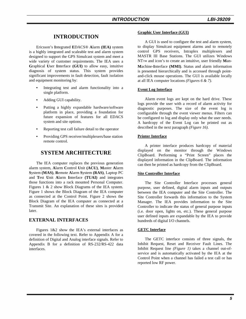
Ericsson’s Integrated EDACS® Alarm (IEA) systemis a highly integrated and scaleable test and alarm systemdesigned to support the GPS Simulcast system and meet awide variety of customer requirements. The IEA uses aGraphical User Interface (GUI) to allow easy, intuitivediagnosis of system status. This system providessignificant improvements in fault detection, fault isolationand equipment monitoring by:
• Integrating test and alarm functionality into asingle platform.
• Adding GUI capability.
• Putting a highly expandable hardware/softwareplatform in place, providing a foundation forfuture expansion of features for all EDACSsystem and site options.
• Reporting test call failure detail to the operator
• Providing GPS receiver/multiplexers/base stationremote control.
SYSTEM ARCHITECTURE
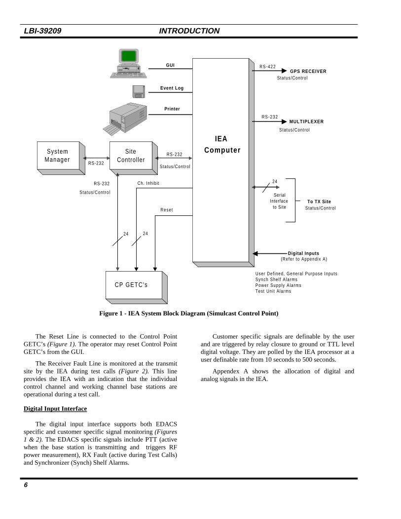
The IEA computer replaces the previous generationalarm system, Alarm Control Unit (ACU), Master AlarmSystem (MAS), Remote Alarm System (RAS), Laptop PCand Test Unit Alarm Interface (TUAI) and integratesthose functions into a rack mounted Personal Computer.Figures 1 & 2 show Block Diagrams of the IEA system.Figure 1 shows the Block Diagram of the IEA computeras connected at the Control Point. Figure 2 shows theBlock Diagram of the IEA computer as connected at aTransmit Site. An explanation of these sites is providedlater.
EXTERNAL INTERFACES
Figures 1&2 show the IEA’s external interfaces ascovered in the following text. Refer to Appendix A for adefinition of Digital and Analog interface signals. Refer toAppendix B for a definition of RS-232/RS-422 datainterfaces.
Graphic User Interface (GUI)
A GUI is used to configure the test and alarm system,to display Simulcast equipment alarms and to remotelycontrol GPS receivers, Intraplex multiplexers andMASTR III Base Stations. The GUI utilizes WindowsNT™ and icon’s to create an intuitive, user friendly Man-
Machine-Interface (MMI) . Status and alarm informationis presented hierarchically and is accessed through point-and-click mouse operations. The GUI is available locallyat all IEA computer locations (Figures 6 & 7).
Event Log Interface
Alarm event logs are kept on the hard drive. Theselogs provide the user with a record of alarm activity fordiagnostic purposes. The size of the event log isconfigurable through the event viewer menus. Filters canbe configured to log and display only what the user needs.A hardcopy of the Event Log can be printed out asdescribed in the next paragraph (Figure 16).
Printer Interface
A printer interface produces hardcopy of materialdisplayed on the monitor through the WindowsClipBoard. Performing a “Print Screen” places thedisplayed information in the ClipBoard. The informationcan then be printed as hardcopy from the ClipBoard.
Site Controller Interface
The Site Controller Interface processes generalpurpose, user defined, digital alarm inputs and outputsbetween the IEA computer and the Site Controller. TheSite Controller forwards this information to the SystemManager. The IEA provides information to the SiteController to indicate the status of general purpose inputs(i.e. door open, lights on, etc.). These general purposeuser defined inputs are expandable by the IEA to providehundreds of digital I/O channels.
GETC Interface
The GETC interface consists of three signals, theInhibit Request, Reset and Receiver Fault Lines. TheInhibit Request line (Figure 1) takes a channel out-of-service and is automatically activated by the IEA at theControl Point when a channel has failed a test call or hasreported low RF power.
LBI-39209 INTRODUCTION
6
RS-232
IEAComputer
RS-232
CP GETC's
2424
Ch. Inhibi t
Reset
24
SerialInterface
to Site
Digital Inputs
To TX Site
Status/Contro l
GPS RECEIVER
MULTIPLEXER
Status/Contro l
Status/Contro l
Status/Contro l
(Refer to Appendix A)
SystemManager
RS-232
Status/Contro l
SiteController
GUI
Event Log
Printer
RS-422
RS-232
User Def ined, Genera l Purpose InputsSynch Shel f A larmsPower Supply A larmsTest Uni t A larms
Figure 1 - IEA System Block Diagram (Simulcast Control Point)
The Reset Line is connected to the Control PointGETC’s (Figure 1). The operator may reset Control PointGETC’s from the GUI.
The Receiver Fault Line is monitored at the transmitsite by the IEA during test calls (Figure 2). This lineprovides the IEA with an indication that the individualcontrol channel and working channel base stations areoperational during a test call.
Digital Input Interface
The digital input interface supports both EDACSspecific and customer specific signal monitoring (Figures1 & 2). The EDACS specific signals include PTT (activewhen the base station is transmitting and triggers RFpower measurement), RX Fault (active during Test Calls)and Synchronizer (Synch) Shelf Alarms.
Customer specific signals are definable by the userand are triggered by relay closure to ground or TTL leveldigital voltage. They are polled by the IEA processor at auser definable rate from 10 seconds to 500 seconds.
Appendex A shows the allocation of digital andanalog signals in the IEA.
INTRODUCTION LBI-39209
7
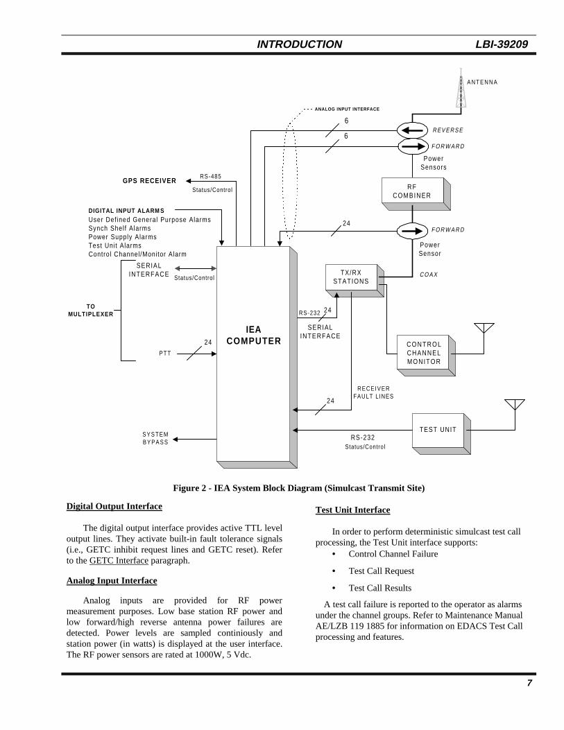
Figure 2 - IEA System Block Diagram (Simulcast Transmit Site)
Digital Output Interface
The digital output interface provides active TTL leveloutput lines. They activate built-in fault tolerance signals(i.e., GETC inhibit request lines and GETC reset). Referto the GETC Interface paragraph.
Analog Input Interface
Analog inputs are provided for RF powermeasurement purposes. Low base station RF power andlow forward/high reverse antenna power failures aredetected. Power levels are sampled continiously andstation power (in watts) is displayed at the user interface.The RF power sensors are rated at 1000W, 5 Vdc.
Test Unit Interface
In order to perform deterministic simulcast test callprocessing, the Test Unit interface supports:
• Control Channel Failure
• Test Call Request
• Test Call Results
A test call failure is reported to the operator as alarmsunder the channel groups. Refer to Maintenance ManualAE/LZB 119 1885 for information on EDACS Test Callprocessing and features.
TEST UNIT
C O N T R O LCHANNELMONITOR
TX/RXSTATIONS
R FCOMBINER
IEACOMPUTER
24
F O R W A R D24
C O A X
6
6
S Y S T E MB Y P A S S
P T T
SERIALINTERFACE
R EV E R S E
F O R W A R D
24
TOMULTIPLEXER
RS-232
RECEIVERFAULT L INES
PowerSensor
PowerSensors
RS-232
SERIALINTERFACE
Status/Control
Status/Control
GPS RECEIVER
DIGITAL INPUT ALARM SUser Def ined General Purpose AlarmsSynch Shelf AlarmsPower Supply AlarmsTest Unit AlarmsControl Channel/Monitor Alarm
Status/Control
RS-485
24
ANALOG INPUT INTERFACE
A N T E N N A
LBI-39209 INTRODUCTION
8
Base Station Receiver Fault Interface
The base station receiver fault interface is used by thetest call processing software to determine whether or notthe test call high speed data handshake took placecorrectly. The interface supports a single TTL level linefrom every channel base station (up to 24 stations).
Push-To-Talk (PTT) Interface
The PTT signal located at the simulcast transmit siteis a TTL level input to the IEA. This signal is activated bythe Control Point when a channel is transmitting RFpower. The IEA uses this signal to trigger the station RFand antenna power monitoring. Refer to Analog Input.
GPS Receiver Interface
The GPS receiver interface provides remote controland status for multiple GPS receiver devices located ateach transmit site and the Control Point. The interface is4-wire, RS-485 running at 9600 bps. For moreinformation on the GPS receiver refer to the appropriatevendor’s maintenance manual.
Intraplex Multiplexer Interface
The Intraplex Multiplexer interface provides remotecontrol and status for multiple multiplexer devices locatedat each transmit site and at the Control Point. Up to 24multiplexers are possible at a simulcast Control Point. Theinterface is a single RS-232 serial interface running at9600 bps to the first multiplexer. Messages are thenbussed between multiplexers on a separate RS-485 Bus.For more information on the Intraplex Multiplexer refer tothe appropriate vendor’s maintenance manual.
MASTR III Base Station Interface
The MASTR III Base Station interface providesremote control for up to 24 base stations. Each stationconnects to the IEA through an RS-232 serial port. Statusof the MASTR III Base Stations gain potentiometers isprovided on the GUI. These potentiometer include:
• DSP Line Pot• DSP Line Cancellation Pot• DSP Comprssor Gain Pot• Line In Pot• Line Out Pot• Transmit Pot• Channel Guard Pot• Voting Tone Gain Pot• Compressor Threshold Pot
The “DSP line in pot” gain is used by an operatorusing the IEA to adjust transmit deviation duringSimulcast system alignment. The remaining pots are not
normally used by the IEA. For more alignmentinformation refer to GPS System Alignment Manual LBI-39210.
Control Point to Transmit Site Interface
The Control Point IEA is the system mastercontroller. All transmit site IEA’s initialize (boot) fromthe Control Point. If communication is lost to a site, theIEA continues to operate and log alarms locally. Whencommunication is restored, the site IEA reboots from theControl Point. Note: any configuration changes made at atransmit site must be made while connected to the ControlPoint or will be overwritten.
Up to 24 IEA computers, located at 24 individual sitelocations, may be connected to a central IEA computerlocated at the simulcast Control Point. Each site link is a19.2k bps data channel through the Intraplex Multiplexeron the inter-site T1/E1 interface. As an option, the IEAwill operate at 9600 bps.
Hardware User Interface
Display Terminal, Keyboard, Mouse
A display terminal, keyboard and mouse are availablefor each IEA computer for a user interface. These itemsare always available at the Control Point and optional atthe TX Site.
Racking
The rackup drawing for the simulcast Control Pointand Transmit Site locations are shown in OverviewMaintenance Manual LBI-39194. The IEA and associatedperipherals are allocated the space designated as “Test &Alarm Computer.”
OPERATION LBI-39209
9
OPERATION
ALARM SYSTEM START/STOP
Automatic On At Power Up
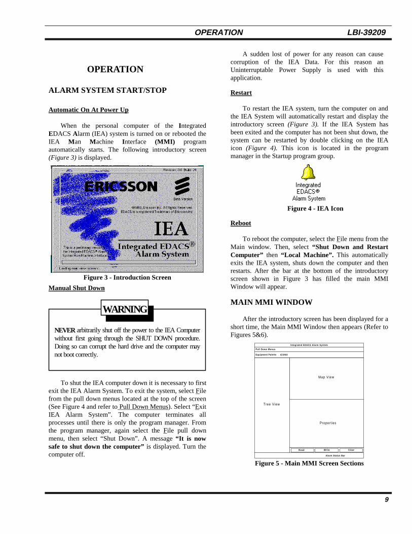
When the personal computer of the IntegratedEDACS Alarm (IEA) system is turned on or rebooted theIEA Man Machine Interface (MMI) programautomatically starts. The following introductory screen(Figure 3) is displayed.
Figure 3 - Introduction Screen
Manual Shut Down
NEVER arbitrarily shut off the power to the IEA Computerwithout first going through the SHUT DOWN procedure.Doing so can corrupt the hard drive and the computer maynot boot correctly.
WARNING
To shut the IEA computer down it is necessary to firstexit the IEA Alarm System. To exit the system, select Filefrom the pull down menus located at the top of the screen(See Figure 4 and refer to Pull Down Menus). Select “ExitIEA Alarm System”. The computer terminates allprocesses until there is only the program manager. Fromthe program manager, again select the File pull downmenu, then select “Shut Down”. A message “It is nowsafe to shut down the computer” is displayed. Turn thecomputer off.
A sudden lost of power for any reason can causecorruption of the IEA Data. For this reason anUninterruptable Power Supply is used with thisapplication.
Restart
To restart the IEA system, turn the computer on andthe IEA System will automatically restart and display theintroductory screen (Figure 3). If the IEA System hasbeen exited and the computer has not been shut down, thesystem can be restarted by double clicking on the IEAicon (Figure 4). This icon is located in the programmanager in the Startup program group.
Figure 4 - IEA Icon
Reboot
To reboot the computer, select the File menu from theMain window. Then, select “Shut Down and RestartComputer” then “Local Machine”. This automaticallyexits the IEA system, shuts down the computer and thenrestarts. After the bar at the bottom of the introductoryscreen shown in Figure 3 has filled the main MMIWindow will appear.
MAIN MMI WINDOW
After the introductory screen has been displayed for ashort time, the Main MMI Window then appears (Refer toFigures 5&6).
Integrated EDACS Alarm System
Pul l Down Menus
Equipment Palette ICO N S
Alarm Status Bar
Read Wri te Clear
Tree View
Map V iew
Propert ies
Figure 5 - Main MMI Screen Sections

LBI-39209 OPERATION
10
Figure 6 - Man-Machine Interface Main Screen
Pull Down Menus
This screen has pull down menus along the top. Thesemenus are File, IEA Database, Options, Diagnostics,Window and Help. Clicking once on a menu activates thatmenu. Another method of selecting these menu items isusing <ALT> and the underline letter.
Selecting File drops:• Load Workspace - Provides a space to
recall settings for individual preferencessuch as background colors, window sizes,etc. This is helpful when more than oneindividual uses the system. Workspacesettings that are saved/restored are:1. Main Window Size2. Equipment Palette On/Off3. Width of tree4. Line style of tree5. Tree boldface or not6. Map boldface or not7. Map background color8. Map line width9. Graph color
• Save Work Space - This selection allowswork space settings to be saved as thepresent workspace.
• Save Work Space As ... - Allows a newwork space to be named and saved
• Remove Work Space - Deletes a previouslydefined workspace. CAUTION: Do notdelete the “Default” workspace.
• Exit IEA System On ØØ - Shuts down theIEA software on a specific machine in thesystem, leaving Windows NT running.
• Exit IEA Alarm System (All Sites) - Shutsdown all IEA software at all sites.
Using the “Exit IEA Alarm System (All Sites)”or “Exit IEA System On.. ØØ” , and selecting aremote machine will require that the sites berestarted manually by rebooting the remotemachine. It is recommended that these optionsnot be used unless the operator is experiencedwith the IEA system and Microsoft WindowsNT.
NOTE
OPERATION LBI-39209
11
• Shut Down and Restart IEA Computer(Machine Name) - Allows any IEAcomputer in the Database to be shut downand completely restarted.
• Shut Down and Restart IEA Computers(All Sites) - Completely shuts down andrestarts all IEA computers in the database.Note: If a site is not connected (shown asgray in tree) it cannot receive the commandto restart and will not restart.
• Resume Operation - Resumes operation ofall IEA Alarm System. When items areadded to the database, the IEA System issuspended. This command resumesoperation of the system using the newdatabase items.
• Exit - The MMI is shut down and all otherprocesses in the Alarm System remainoperational. Note: The MMI will berestarted by the boot process if it is running.If the desire is to turn the MMI off until thesystem is restarted, it should be shut off byselecting the BOOT.EXE process andpressing “M”.
Selecting IEA Data Base drops:• Connect - Connects IEA to Data Base• Connect To - another machine. Will ask for
the address of the other machine.• Disconnect - Disconnects IEA from Data
Base• View Connection Info - Provides
information about internal softwareconnections.
• Print - Prints a detail summary of thedatabase structure and contents in thewindow labeled ROUTER.EXE.
• Write To Disk - Forces the current databasecontents to be stored on the hard disk of allIEA computers. Each time a property ischanged and the “Write” button is pressedthe database is also saved to disk.
Selecting Options drops:• Tree View - Allows selection of bold face
font and line style
• Map View - Allows arrangement of icons,selection of bold face font, backgroundcolor, line thickness and line color.
• Properties View - Allows setting ofmaximum number of error messages when indiagnostics mode. Should Not be adjustedby the customer.
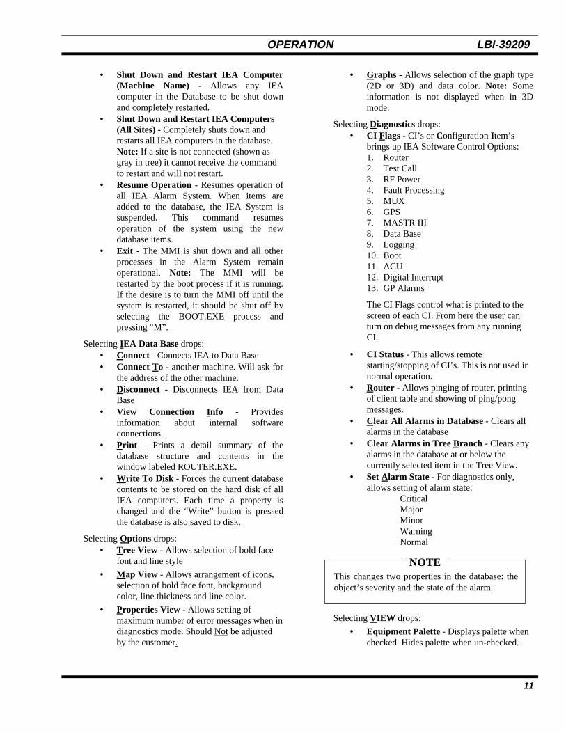
• Graphs - Allows selection of the graph type(2D or 3D) and data color. Note: Someinformation is not displayed when in 3Dmode.
Selecting Diagnostics drops:• CI Flags - CI’s or Configuration I tem’s
brings up IEA Software Control Options:1. Router2. Test Call3. RF Power4. Fault Processing5. MUX6. GPS7. MASTR III8. Data Base9. Logging10. Boot11. ACU12. Digital Interrupt13. GP Alarms
The CI Flags control what is printed to thescreen of each CI. From here the user canturn on debug messages from any runningCI.
• CI Status - This allows remotestarting/stopping of CI’s. This is not used innormal operation.
• Router - Allows pinging of router, printingof client table and showing of ping/pongmessages.
• Clear All Alarms in Database - Clears allalarms in the database
• Clear Alarms in Tree Branch - Clears anyalarms in the database at or below thecurrently selected item in the Tree View.
• Set Alarm State - For diagnostics only,allows setting of alarm state:
CriticalMajorMinorWarningNormal
This changes two properties in the database: theobject’s severity and the state of the alarm.
NOTE
Selecting VIEW drops:
• Equipment Palette - Displays palette whenchecked. Hides palette when un-checked.

LBI-39209 OPERATION
12
• Latched Alarm Tree - Displays the LatchedAlarm Tree
• Alarm History - Displays history log, whichtypically includes the last 50 alarm events.
• System Event Log - Displays the SystemEvent Log
Selecting Help drops:• About - Displays the “About” screen as
shown in Figure 3.
Equipment Palette
The “Equipment Palette” , is a row of icons arrangedaccording to system hierarchy. This is important to knowwhen building the system since this arrangementestablishes the order of construction. Selection of any oneof these icon’s starts a “wizard” which facilitates systemconfiguration. Icon’s are from left to right:
1. Add An Extended Network - TheExtended Network links Multisite Networks tocover very large areas, such as a state or country.This icon starts a “wizard” which adds anextended network, and is only valid when thecurrent tree item is a customer.
2. Add A Multisite Network - A MultisiteNetwork links systems together through anIntegrated Multisite and Console Controller(IMC). This icon starts a “wizard” which addsmultisites into the system and is only valid whenthe current tree item is an Extended Network.
3. Add An EDACS System - An EDACSsystem provides coordinated communicationbetween agencies and integrates all services suchas Dispatch, Secure Voice, telephone and Datawith a single common communication system.This icon starts a “wizard” which adds anEDACS System and is only valid when thecurrently selected item in the tree view is aMultisite Network.
4. Add An EDACS Site - An EDACS sitecan be designated as a GPS Simulcast ControlPoint, Transmit/Receive Site or a Receive onlysite. This icon starts a “wizard” which adds asite to the alarm system and is only valid whenthe currently selected item in the tree view is anEDACS system.
The first four icon’s establish the communicationsystem with the IEA. The next six (6) icons add
characteristics or equipment of the communication systemto the IEA.
5. Add A Channel - This icon activates awizard which adds a channel to the selected site.Channels can be added to either a site object or achannels group object in the tree.
6. Add A GPS Receiver - This icon activatesa wizard which adds a GPS Receiver(s) to theselected site (typically 2). GPS Receivers may beadded to either a site or a GPS Receivers groupin the tree.
7. Add A Multiplexer - This icon activates awizard which adds Multiplexer(s) to the selectedsite for a maximum of 24. Multiplexers may beadded to either a site or a Multiplexer group inthe tree.
8. Add An Antenna - This icon activates awizard which adds an antenna(s) to the selectedsite for a maximum of 6. Antennas may be addedto either side or an Antennas group in the tree.
9. Add A Digital Alarm Group - This iconactivates a wizard which adds a General PurposeDigital I/O Function Group to the Alarm System.Digital Alarm Groups are used to groupfunctionally similar digital inputs, such as doorand window alarms, temperature alarms, etc.,into organized branches in the tree. Thisorganization reduces screen redraw times, keepsthe number of inputs to a manageable level, andkeeps the large number of possible inputsorganized into groups that serve a similarpurpose. Digital Alarm Groups may only beadded when the currently selected item in the treeis the “DIGITAL ALARMS” item below a site.
10. Add A Digital Input Alarm - This iconactivates a wizard which adds a General PurposeDigital Input Point to the selected site for amaximum of 168 (refer to Appendix A). DigitalInput Points may only be added when thecurrently selected item in the tree view is aDigital Alarm Function Group.
OPERATION LBI-39209
13
Tree View
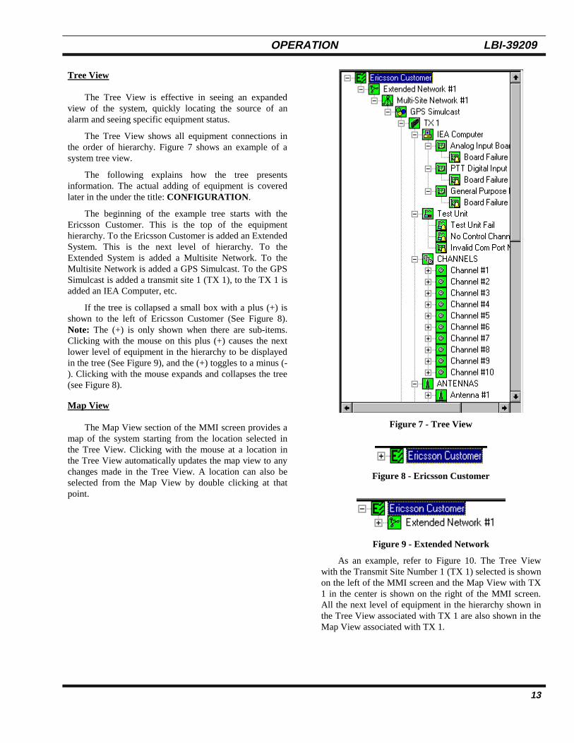
The Tree View is effective in seeing an expandedview of the system, quickly locating the source of analarm and seeing specific equipment status.
The Tree View shows all equipment connections inthe order of hierarchy. Figure 7 shows an example of asystem tree view.
The following explains how the tree presentsinformation. The actual adding of equipment is coveredlater in the under the title: CONFIGURATION .
The beginning of the example tree starts with theEricsson Customer. This is the top of the equipmenthierarchy. To the Ericsson Customer is added an ExtendedSystem. This is the next level of hierarchy. To theExtended System is added a Multisite Network. To theMultisite Network is added a GPS Simulcast. To the GPSSimulcast is added a transmit site 1 (TX 1), to the TX 1 isadded an IEA Computer, etc.
If the tree is collapsed a small box with a plus (+) isshown to the left of Ericsson Customer (See Figure 8).Note: The (+) is only shown when there are sub-items.Clicking with the mouse on this plus (+) causes the nextlower level of equipment in the hierarchy to be displayedin the tree (See Figure 9), and the (+) toggles to a minus (-). Clicking with the mouse expands and collapses the tree(see Figure 8).
Map View
The Map View section of the MMI screen provides amap of the system starting from the location selected inthe Tree View. Clicking with the mouse at a location inthe Tree View automatically updates the map view to anychanges made in the Tree View. A location can also beselected from the Map View by double clicking at thatpoint.
Figure 7 - Tree View
Figure 8 - Ericsson Customer
Figure 9 - Extended Network
As an example, refer to Figure 10. The Tree Viewwith the Transmit Site Number 1 (TX 1) selected is shownon the left of the MMI screen and the Map View with TX1 in the center is shown on the right of the MMI screen.All the next level of equipment in the hierarchy shown inthe Tree View associated with TX 1 are also shown in theMap View associated with TX 1.

LBI-39209 OPERATION
14
Figure 10 - Map View
Properties View
The properties view of the MMI provides informationabout the status and configuration of the currently selecteditem in the tree view. Depending upon the type of itemthat is selected, a different set of tabs and properties aredisplayed.
The Properties View section of the MMI screenprovides tabs labeled:
• General• Power Meas.• RF Power Summary• RF Power• FWD Power• REV Power• DSP/Line/Out• TX/CG/VT/CT/MID• Severity• Time-outs• Receiver• Time/Date/ Position• Timing Param’s• Notes
Depending on what object is selected in the tree view,the property view displays a General tab, a Notes tab, andany tabs associated with properties of the selected object.Tabs are related to specific equipment in a specific MapView. For example, when the Map View is active the tabsshown in Figure 11 are active.
Following Figure 11 is a brief description of each taband the properties that may be found.
Figure 11 - Example of Properties View Showing Tabs
General Tab
This tab is present for all objects in the database,although different types of objects will have differentcombinations of properties present on the tab. The generaltab displays a combination of the following objectproperties:
Description - This property determines the text usedto identify the object in the map and tree views of thedatabase. The description for any object in thedatabase can be changed by the user, although careshould be taken when renaming alarm items, since thealarm’s function is indicated by its name.
To change the description of an object in thedatabase, select the item in the tree view and wait forthe properties view to update. Next, change the text inthe description field and press the Write button.When the text returns to black, the new descriptionhas been written to the database and all subsequentoperation will use the new description.
Alarm Threshold - This controls which alarmindications are allowed to pass up the tree hierarchyto the next level. In other words, if this property is setto Major, then only Major and higher severity alarmsbelow this object in the tree affect the object’s color.
OPERATION LBI-39209
15
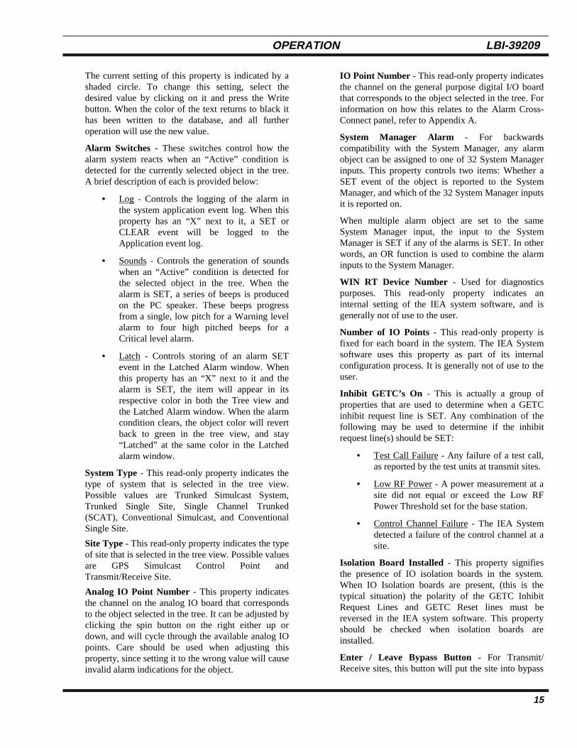
The current setting of this property is indicated by ashaded circle. To change this setting, select thedesired value by clicking on it and press the Writebutton. When the color of the text returns to black ithas been written to the database, and all furtheroperation will use the new value.
Alarm Switches - These switches control how thealarm system reacts when an “Active” condition isdetected for the currently selected object in the tree.A brief description of each is provided below:
• Log - Controls the logging of the alarm inthe system application event log. When thisproperty has an “X” next to it, a SET orCLEAR event will be logged to theApplication event log.
• Sounds - Controls the generation of soundswhen an “Active” condition is detected forthe selected object in the tree. When thealarm is SET, a series of beeps is producedon the PC speaker. These beeps progressfrom a single, low pitch for a Warning levelalarm to four high pitched beeps for aCritical level alarm.
• Latch - Controls storing of an alarm SETevent in the Latched Alarm window. Whenthis property has an “X” next to it and thealarm is SET, the item will appear in itsrespective color in both the Tree view andthe Latched Alarm window. When the alarmcondition clears, the object color will revertback to green in the tree view, and stay“Latched” at the same color in the Latchedalarm window.
System Type - This read-only property indicates thetype of system that is selected in the tree view.Possible values are Trunked Simulcast System,Trunked Single Site, Single Channel Trunked(SCAT), Conventional Simulcast, and ConventionalSingle Site.
Site Type - This read-only property indicates the typeof site that is selected in the tree view. Possible valuesare GPS Simulcast Control Point andTransmit/Receive Site.
Analog IO Point Number - This property indicatesthe channel on the analog IO board that correspondsto the object selected in the tree. It can be adjusted byclicking the spin button on the right either up ordown, and will cycle through the available analog IOpoints. Care should be used when adjusting thisproperty, since setting it to the wrong value will causeinvalid alarm indications for the object.
IO Point Number - This read-only property indicatesthe channel on the general purpose digital I/O boardthat corresponds to the object selected in the tree. Forinformation on how this relates to the Alarm Cross-Connect panel, refer to Appendix A.
System Manager Alarm - For backwardscompatibility with the System Manager, any alarmobject can be assigned to one of 32 System Managerinputs. This property controls two items: Whether aSET event of the object is reported to the SystemManager, and which of the 32 System Manager inputsit is reported on.
When multiple alarm object are set to the sameSystem Manager input, the input to the SystemManager is SET if any of the alarms is SET. In otherwords, an OR function is used to combine the alarminputs to the System Manager.
WIN RT Device Number - Used for diagnosticspurposes. This read-only property indicates aninternal setting of the IEA system software, and isgenerally not of use to the user.
Number of IO Points - This read-only property isfixed for each board in the system. The IEA Systemsoftware uses this property as part of its internalconfiguration process. It is generally not of use to theuser.
Inhibit GETC’s On - This is actually a group ofproperties that are used to determine when a GETCinhibit request line is SET. Any combination of thefollowing may be used to determine if the inhibitrequest line(s) should be SET:
• Test Call Failure - Any failure of a test call,as reported by the test units at transmit sites.
• Low RF Power - A power measurement at asite did not equal or exceed the Low RFPower Threshold set for the base station.
• Control Channel Failure - The IEA Systemdetected a failure of the control channel at asite.
Isolation Board Installed - This property signifiesthe presence of IO isolation boards in the system.When IO Isolation boards are present, (this is thetypical situation) the polarity of the GETC InhibitRequest Lines and GETC Reset lines must bereversed in the IEA system software. This propertyshould be checked when isolation boards areinstalled.
Enter / Leave Bypass Button - For Transmit/Receive sites, this button will put the site into bypass

LBI-39209 OPERATION
16
or remove it from bypass, depending on the currentstate of the site.
Reset GETC’s Button - Available only at a controlpoint, this button will toggle the GETC Reset line atthe site, resetting all GETC’s at the site.
Severity Tab
The Severities Tab is available for all alarm andstatus (On/Off) items in the database. The followingproperties can be found on the severity tab:
Alarm Severity - This controls the severity level thatis used when reporting an “In alarm” state for theselected object in the tree view. This property is notpresent for status items (Those with values ofOn/Off).
Present Status - This read-only property displays thecurrent status of the item in the database. Thebackground of the text corresponds to the severitythat the alarm has been configured to.
Alarm Polarity - This determines the polarity thatthe IEA System uses to determine if an alarm is SETor CLEARED. Note that this is hardware dependent,and should not be changed arbitrarily.
Reason For Last - Read-Only text field is present forboards under the IEA computer object in thedatabase. When an IO board failure alarm is SET, thisfield contains information describing the reason forthe failure.
Alarm if Less Than (Watts) - This property is onlyavailable for Antenna Low Forward Power andStation Low RF Power alarms. It controls thethreshold at which an alarm is SET. When themeasured power level is less than this setting, thecorresponding alarm is SET.
Alarm if More Than (Watts) - This property is onlyavailable for Antenna High Reverse Power. Itcontrols the threshold at which an alarm is SET.When the measured power level is greater than thissetting, the corresponding alarm is SET.
Power Meas. Tab
This tab is only visible when a Site is selected in thetree view. It controls internal software parameters for theIEA System’s power measurement reporting algorithm. Ateach site, power is measured and packaged into “reports”,which are sent to the user interface at a predeterminedtime. By varying the values of these parameters, one canadjust the balance of system loading vs. real-time updatesof the power measurement graphs.
Max Measuremnt’s Per Report - This propertycontrols the maximum number of measurements perreport sent to the user interface. On very activesystems, this forces power measurement reports everyn measurements, and measurements are not lost.
Max Seconds Between Reports - This propertycontrols the maximum time between reports. Onsystems with very little activity, this forces an updateat the user interface at timed intervals.
Max Samples Per Calc. - This property is usedinternally by the IEA software. It controls themaximum number of analog samples that are used fora power calculation. When the number of analogsamples specified by this property are taken, a powermeasurement value is calculated and placed in thereport for transmission to the user interface.
This property forces reporting on the power level ofthe control channel. Since the PTT signal on thecontrol channel never resets, without this property ameasurement would not be calculated.
Delay After PTT - This property is used to set thedelay following an active PTT signal before analogpower samples are taken. Since base stations takesome time to reach full steady-state power, thisproperty ensures an accurate power measurement.
Delay Between Samples - This property controls thesampling frequency of the power sensors, and shouldnot be adjusted by the user.
RF Power Summary Tab
This tab is only visible when the CHANNELS objectat a site is selected in the tree view, and contains a graphthat displays the last measured power value for eachchannel or station at the site (Figure 12). It is updatedeach time a power report is received from the site (SeePower Measurement Tab description above for moredetail regarding when reports are sent).
Important features of the graph include:
• Power bar for each Channel - A bar isplotted for each channel or antenna at thesite.
• Numeric indication of measured value - Atthe top of the bar, the numerical value of themeasurement is printed. This is onlyavailable when the graph style is set to 2DBar.
• Threshold settings for each Channel - A lineindicates the threshold setting for a Low RFPower alarm for each station at the site.

OPERATION LBI-39209
17
• Indication of Control Channel - A (CC) isprinted next to the numerical value of thecontrol channel, and the bar is shaded with ahatch pattern to indicate the channelcurrently being used as the control channel.
• Indication of channel under test - A (TST) isprinted next to the numerical value of thechannel under test (If any), and the bar isshaded with a cross-hatch pattern to indicatethat the channel is currently being used tomake a test call. This indication is performedin real-time as the test call is performed.
• Red bar for alarm - If at any time themeasured power value drops below the LowRF Power alarm threshold, the bar for thatchannel will be displayed in red to indicatethat it is in alarm.
Pow
er (
w)
Channe l1 2 3 4
75
105(CC)
80
70(TST)
Low RF PowerAlarm Threshold
ControlChannel
Exact ValueMeasured
Red ( In Alarm)
Figure 12 - Station RF Power Summary
Antenna Power Summary Tab
This tab is only visible when the ANTENNAS objectat a site is selected in the tree view, and contains twographs side-by-side (Figure 13). The first graph displaysthe last measured value of forward antenna power for eachantenna at the site, and the second displays the lastmeasured value of reverse antenna power for each antennaat the site. Graph features include the following:
• Power bar for each antenna - A bar is plottedfor each antenna at the site.
• Numeric indication of measured value - Atthe top of the bar, the numerical value of themeasurement is printed. This is onlyavailable when the graph style is set to 2DBar.
• Threshold settings for each antenna - A lineindicates the threshold setting for LowForward Antenna Power Alarm, or a HighReverse Antenna Power Alarm.
• Red bar for alarm - If at any time themeasured power value drops below the LowForward Antenna Power Alarm or HighReverse Antenna Power Alarm threshold,the bar for that antenna will be displayed inred to indicate that it is in alarm.
Antenna
Pow
er (
W)
205
340
220197
1 2 3 4
FWD Antenna Power-Last Meas. Value
Antenna
Pow
er (
W)
25
100
75
1 2 3 4
REV Antenna Power-Last Meas. Value
50
Figure 13- Antenna Forward/Reverse PowerSummary
RF Power Tab
This tab is only present for a Channel or Stationobject. It contains a graph that displays the last 50measurements of power and the current Low RF PowerAlarm Threshold for the selected corresponding basestation. The measurements progress in time from left toright, with the most recent measurement on the right. Asnew measurements are received, the graph scrolls to theleft and the new value is plotted. Note that the graph isonly updated once for every power report, not once forevery measurement. Refer to the section on the PowerMeasurement Tab for more details on power reports.

LBI-39209 OPERATION
18
Forward Power Tab
This tab is only present for an Antenna. It contains agraph that displays the last 50 measurements of ForwardAntenna Power and the current Low Forward AntennaPower Alarm Threshold for the selected Antenna. Themeasurements progress in time from left to right, with themost recent measurement on the right. As newmeasurements are received, the graph scrolls to the leftand the new value is plotted. Note that the graph is onlyupdated once for every power report, not once for everymeasurement. Refer to the section on the PowerMeasurement Tab for more details on power reports.
Reverse Power Tab
This tab is only present for an Antenna. It contains agraph that displays the last 50 measurements of ReverseAntenna Power and the current High Reverse AntennaPower Alarm Threshold for the selected Antenna. Themeasurements progress in time from left to right, with themost recent measurement on the right. As newmeasurements are received, the graph scrolls to the leftand the new value is plotted. Note: the graph is onlyupdated once for every power report, not once for everymeasurement. Refer to the section on the PowerMeasurement Tab for more details on power reports.
Receiver Tab
This tab is only visible for GPS Receivers, andprovides general information about the receiver. Thefollowing properties are provided:
Manufacturer’s Info - These properties are read-only, and are read from the internal ROM of thereceiver. They include:
• Vendor - The name of the receiver vendor.
• Model - The model number of the receiver.
• Serial No. - The serial number of thereceiver (if implemented).
• Firmware Revision - The revision of theinternal firmware of the receiver.
Receiver Status - These read-only properties indicateinformation measured by the receiver.
• Internal Temperature - The internaltemperature of the GPS receiver, measuredin degrees C.
• Satellites Tracked - The number of satellitescurrently tracked. Note that when thisnumber drops below 4 the receiver is
considered to have lost Lock status andbegins timing out on the GPS Lock Alarm.
Time/Date/Pos Tab
This tab is only present for GPS Receivers, andindicates the time, date, and position measurements asreported by the receiver. While values can be set by theuser, they will be overwritten by the IEA software once alocked status is reported by the receiver.
Time and Date - The time, date, and Time Zone, asdetermined by the GPS Receiver.
Position - The position of the receiver, includingLatitude, Longitude, and Altitude.
Timing Param's Tab
This tab is only present for GPS Receivers, andprovides control of the two GPS Receiver timingproperties as described below:
One Pulse per Second Offset - This controls theamount of delay to place on the One Pulse PerSecond output of the Receiver. This is typically onlyadjusted during system alignment.
Antenna Cable Delay - This controls the amount ofdelay with which to compensate for antenna cablelength. This is typically only adjusted during systemalignment.
Time-outs Tab
This tab is only present for the following three GPSReceiver alarms: 9.6kHz Alarm 10MHz Output Alarm,and GPS Lock Alarm. The tab will contain a combinationof the following properties:
Timeout Value - This property controls the amountof time that the GPS Receiver is allowed to runwithout a locked timing signal before the alarm isSET. Individual settings are available for each of thethree outputs of the receiver; 9.6 kHz, 10 MHz, andGPS Locked status.
The value is entered in days, hours, minutes andseconds.
Time Remaining - This read-only property indicatesthe time remaining before the corresponding alarm isSET. If the GPS Receiver is locked to 4 or moresatellites this value should be the same as the TimeoutValue property (See above). When the receiver loseslock with the satellites, the value of this parameterdecreases to zero and the alarm is SET.
OPERATION LBI-39209
19
Note: The value of this parameter does not update onthe tab in real-time, and must be explicitly “Read”using the read button at the bottom of the window.
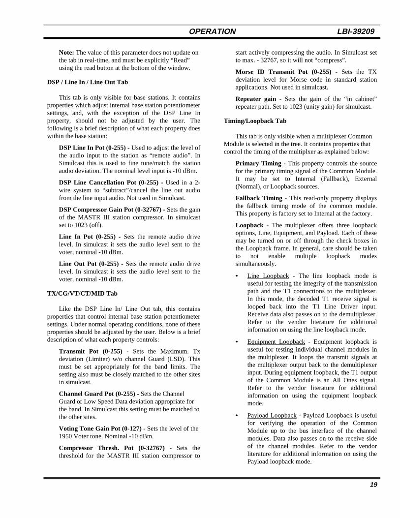
DSP / Line In / Line Out Tab
This tab is only visible for base stations. It containsproperties which adjust internal base station potentiometersettings, and, with the exception of the DSP Line Inproperty, should not be adjusted by the user. Thefollowing is a brief description of what each property doeswithin the base station:
DSP Line In Pot (0-255) - Used to adjust the level ofthe audio input to the station as “remote audio”. InSimulcast this is used to fine tune/match the stationaudio deviation. The nominal level input is -10 dBm.
DSP Line Cancellation Pot (0-255) - Used in a 2-wire system to “subtract”/cancel the line out audiofrom the line input audio. Not used in Simulcast.
DSP Compressor Gain Pot (0-32767) - Sets the gainof the MASTR III station compressor. In simulcastset to 1023 (off).
Line In Pot (0-255) - Sets the remote audio drivelevel. In simulcast it sets the audio level sent to thevoter, nominal -10 dBm.
Line Out Pot (0-255) - Sets the remote audio drivelevel. In simulcast it sets the audio level sent to thevoter, nominal -10 dBm.
TX/CG/VT/CT/MID Tab
Like the DSP Line In/ Line Out tab, this containsproperties that control internal base station potentiometersettings. Under normal operating conditions, none of theseproperties should be adjusted by the user. Below is a briefdescription of what each property controls:
Transmit Pot (0-255) - Sets the Maximum. Txdeviation (Limiter) w/o channel Guard (LSD). Thismust be set appropriately for the band limits. Thesetting also must be closely matched to the other sitesin simulcast.
Channel Guard Pot (0-255) - Sets the ChannelGuard or Low Speed Data deviation appropriate forthe band. In Simulcast this setting must be matched tothe other sites.
Voting Tone Gain Pot (0-127) - Sets the level of the1950 Voter tone. Nominal -10 dBm.
Compressor Thresh. Pot (0-32767) - Sets thethreshold for the MASTR III station compressor to
start actively compressing the audio. In Simulcast setto max. - 32767, so it will not “compress”.
Morse ID Transmit Pot (0-255) - Sets the TXdeviation level for Morse code in standard stationapplications. Not used in simulcast.
Repeater gain - Sets the gain of the “in cabinet”repeater path. Set to 1023 (unity gain) for simulcast.
Timing/Loopback Tab
This tab is only visible when a multiplexer CommonModule is selected in the tree. It contains properties thatcontrol the timing of the multiplxer as explained below:
Primary Timing - This property controls the sourcefor the primary timing signal of the Common Module.It may be set to Internal (Fallback), External(Normal), or Loopback sources.
Fallback Timing - This read-only property displaysthe fallback timing mode of the common module.This property is factory set to Internal at the factory.
Loopback - The multiplexer offers three loopbackoptions, Line, Equipment, and Payload. Each of thesemay be turned on or off through the check boxes inthe Loopback frame. In general, care should be takento not enable multiple loopback modessimultaneously.
• Line Loopback - The line loopback mode isuseful for testing the integrity of the transmissionpath and the T1 connections to the multiplexer.In this mode, the decoded T1 receive signal islooped back into the T1 Line Driver input.Receive data also passes on to the demultiplexer.Refer to the vendor literature for additionalinformation on using the line loopback mode.
• Equipment Loopback - Equipment loopback isuseful for testing individual channel modules inthe multiplexer. It loops the transmit signals atthe multiplexer output back to the demultiplexerinput. During equipment loopback, the T1 outputof the Common Module is an All Ones signal.Refer to the vendor literature for additionalinformation on using the equipment loopbackmode.
• Payload Loopback - Payload Loopback is usefulfor verifying the operation of the CommonModule up to the bus interface of the channelmodules. Data also passes on to the receive sideof the channel modules. Refer to the vendorliterature for additional information on using thePayload loopback mode.

LBI-39209 OPERATION
20
Framing/Coding Tab
This tab is only visible when a Common Module isselected in the tree view. It provides control of theframing and coding modes of the common module asdescribed below:
Framing - The framing format of the Commonmodule can be set to either SF (Super Frame) or ESF(Extended Super Frame). ESF is the preferred format,unless the network or channel service unit cannotsupport it. Refer to the vendor literature for additionaldetails on setting the framing format.
Coding - Line coding can be set to either B8ZS(Bipolar with 8 Zero Substitution) or AMI (AlternateMark Inversion). B8ZS is the preferred format, andshould always be used unless the network or ChannelService unit cannot support it. Refer to the vendorliterature for additional details on setting the linecoding.
Settings Tab
This tab is present when a Multiplexer T1 Module isselected in the tree view. It contains properties that controlthe T1 Module. Normal operation of the Multiplexerrequires the T1 Module to be placed in Local control,during which many of the properties are read-only andcannot be adjusted. If an attempt is made to adjust on ofthese properties, the user will receive a message indicatingthat the parameter cannot be adjusted. Below is a briefdescription of the properties on this tab:
Requested Delay - This controls the T1 Delay settingin the multiplexer. When this value is set, themultiplexer will either immediately change the delaysetting internally (Step Transition, or SmoothTransition Mode OFF), or begin a slow transition tothe new value (Smooth Transition Mode).
Actual Delay - The T1 Module has discrete valuesthat the delay can be set to. If a value is requested thatdoes not match one of these discrete values, the delayis set to the nearest one. This property indicates theactual value that the delay is set to. In addition, if themodule is making a transition to a new value, thisproperty displays the current value of the delayparameter. Note that this is not updated in real-timeand must be updated using the Read Button at thebottom of the main window.
Control Mode - This read-only property indicates thecurrent control mode of the T1 Module. The modulecan operate in either Local (Default) or remote
modes. The current operating mode can only be setby physically changing switch settings on the module.
Settings - The T1 module has several settings thatcan be adjusted by the user. This properties groupallows control of these settings. The following is abrief description of each setting. For moreinformation, refer to the multiplexer vendor’sdocumentation.
• In Service - This property indicates that theselected T1 Module is in use at the presenttime.
• Smooth Trans. - This property indicateswhether smooth transition mode (Hitless) isenabled (Default value) or not. Whenenabled, any change to the T1 delay is madegradually, allowing the delay to changewithout losing T1 synchronization. Whendisabled, a step change is made to the T1Delay, causing a momentary loss ofsynchronization until the module canestablish lock again.
• Ext. Timing On - This property indicateswhether an external timing signal is beingused for transmit timing. When this propertyis checked, the module is using an externalRS-422 clock at 1.544 MHz. When it is notchecked, the module is using an internalCM-3A timing source (Internal orLoop/Thru timing) for transmit timing.
• 422 Inverted - This property controlswhether the RS-422 control signal isinverted or not. When this property ischecked, the signal is inverted.
Port Directions Tab
This tab is only visible for a General Purpose DigitalIO Board. It provides read-only status of the board’s IOport configuration. The input/output pins on each boardare divided into groups of eight, and each group (Port) canbe configured as either inputs or outputs. This tabprovides a tabular display of each available port, and thedirection that it is configured in.
Notes Tab
The notes tab is visible for every object in the IEASystem. It provides a place where up to 500 bytes ofinformation may be entered and stored in the database.Several points should be considered when using the notesfield of the IEA System:
OPERATION LBI-39209
21
Database Size - The notes are stored within thedatabase itself, which will directly effect its size, andhence the time to load and transfer it into thecomputer. Some tips to remember:
• Keep notes brief.• Place notes at the highest applicable level in
the hierarchy.
Persistence - The notes entered into this tab arepersistent - That is, they remain in the database untilthey are explicitly erased or the database is rebuilt.The notes section, therefore, remains present even ifthe power to the system is shut off or the systemreboots.
System Wide - Notes are present in the database atall sites while the sites are connected. Notes enteredwhile the sites are connected will be present at a sitethat is no longer connected to the control point. Inthis condition, remember that when the site re-connects to the control point the Control Point’sdatabase will overwrite the database at the site, so anychanges to the notes field while the site isdisconnected will be lost.
LBI-39209 OPERATION
22
USING THE SYSTEM
Alarms
Alarm indications (normal/alarm) are represented bythe background color of the item, in the hierarchy tree andmap view, according to the severity of the alarmcondition. The actual color of the item follows theNetwork Manager standard for Critical, Major, Minor,Warning and Normal level of severity.Disabled/Off/Active and Not Active indications are alsoavailable for some alarms and equipment in the hierarchytree. The highest severity of an alarm climbs the tree tothe highest level. The colors normally representing theseverity of an alarm are:
• Green - Normal Operation
• Red - Critical
• Orange - Major
• Yellow - Minor
• Cyan (light blue) - Warning
• Gray - OFF
To set the severity of a particular alarm, click on thealarm in the Tree View and then select the Severity Tabfrom the Properties View. Select the desired severity levelby clicking on it with the left mouse button, and write it tothe database by pushing the Write button. When the colorof the severity text returns to black, the value has beenstored to the database:
An alarm threshold can be established by going to theProperties section, General tab and Alarm Threshold ofthe MMI screen and selecting:
• No Alarms
• Critical
• Major
• Minor
• Warning
These affect the propagation of the alarm indicationsup the tree. As an example, “Major” means that onlymajor or higher severity alarms are reflected in the item’stree and map views.
“No Alarm” means that no alarms below that item aredisplayed in the Tree View. “Critical” means only criticalalarms are displayed. “Major” mean major and criticalalarms are displayed. “Minor” means minor, major andcritical alarms are displayed. “Warning” means warning,minor, major and critical alarms are displayed.
When the alarm threshold has been selected, all of theconditions are displayed in blue. This means that they
have been selected but not written to the database.Pressing the Write button at the bottom of the screenwrites the information to the database. The conditions arethen displayed in black.
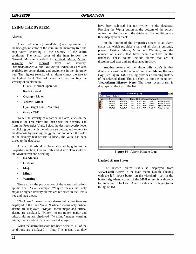
At the bottom of the Properties screen is an alarmstatus bar which provides a tally of all alarms currentlypresent: Critical, Major, Minor and Warning, and thenumber of alarms that have been “latched” in thedatabase. These counts include alarms that are atdisconnected sites and are displayed in Gray.
Another feature of the alarm tally icon’s is thatdouble clicking on the icon activates an Alarm HistoryLog (See Figure 14). This log provides a running historyof the selected alarm. This is a short cut for the menu itemView/Alarm History . Note: The most recent alarm isdisplayed at the top of the list.
Figure 14 - Alarm History Log
Latched Alarm Status
The latched alarm status is displayed fromView/Latch Alarm in the main menu. Double clickingwith the left mouse button on the “latched” icon in thebottom right-hand corner of the MMI screen is a shortcutto this screen. The Latch Alarms status is displayed (referto Figure 15).
OPERATION LBI-39209
23
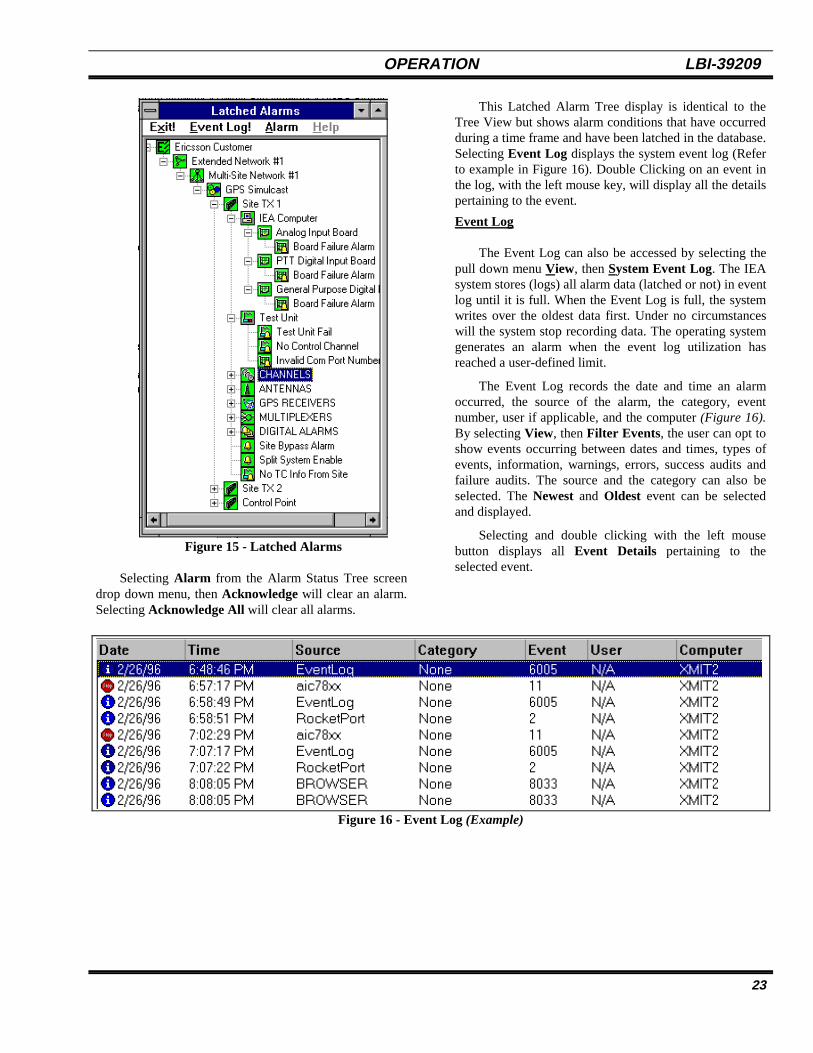
Figure 15 - Latched Alarms
Selecting Alarm from the Alarm Status Tree screendrop down menu, then Acknowledge will clear an alarm.Selecting Acknowledge All will clear all alarms.
This Latched Alarm Tree display is identical to theTree View but shows alarm conditions that have occurredduring a time frame and have been latched in the database.Selecting Event Log displays the system event log (Referto example in Figure 16). Double Clicking on an event inthe log, with the left mouse key, will display all the detailspertaining to the event.
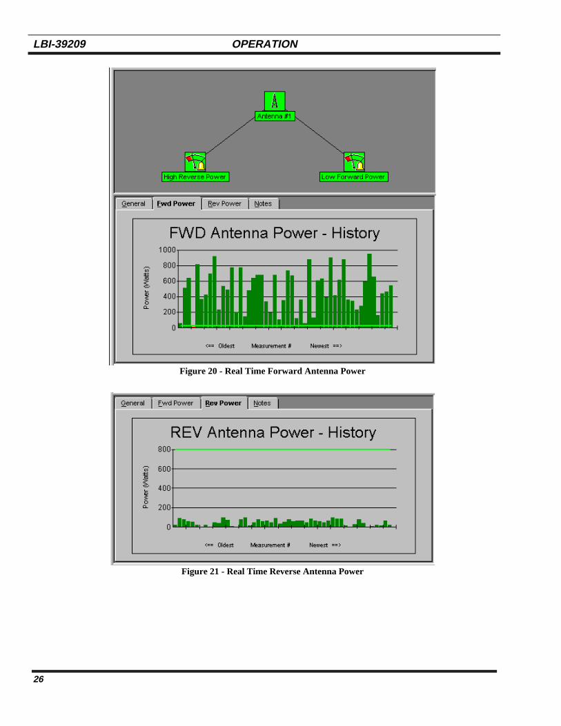
Event Log
The Event Log can also be accessed by selecting thepull down menu View, then System Event Log. The IEAsystem stores (logs) all alarm data (latched or not) in eventlog until it is full. When the Event Log is full, the systemwrites over the oldest data first. Under no circumstanceswill the system stop recording data. The operating systemgenerates an alarm when the event log utilization hasreached a user-defined limit.
The Event Log records the date and time an alarmoccurred, the source of the alarm, the category, eventnumber, user if applicable, and the computer (Figure 16).By selecting View, then Filter Events, the user can opt toshow events occurring between dates and times, types ofevents, information, warnings, errors, success audits andfailure audits. The source and the category can also beselected. The Newest and Oldest event can be selectedand displayed.
Selecting and double clicking with the left mousebutton displays all Event Details pertaining to theselected event.
Figure 16 - Event Log (Example)

LBI-39209 OPERATION
24
RF Power
The Properties View provides tabs for a powersummary of each channel and for measuring real timeforward and reverse RF power to the antenna. Thesemeasurements are used to monitor if the MASTR III BaseStation and its associated antenna. While transmitting, thepower output from the station and antenna is measuredand compared against a threshold to determine if a low RFpower alarm should be generated. The powermeasurements are also collected to provide trend analysisand other statistics.
When a TX Site is selected from the Tree View, theProperties View provides a Power Meas. tab (Figure 17).This tab allows the operator to set:
• Maximum measurements per report
• Maximum seconds between reports
• Maximum samples per calculation
• Delay after PTT in milliseconds
• Delay between samples
Additional information about these settings isavaliable in the Operation Section titled Power Meas.Tab.
Selecting CHANNELS from the Tree View, then thePower Summary tab from the Properties View, displaysgraphs as shown in Figure 18. These graphs provides acontinuous indication of the power level (in watts) of eachchannel in the system. The line indicate the thresholdlevel. When the power falls below this level, the IEAsystem initiates an alarm.
Selecting ANTENNAS from the Tree View, then thePower Summary tab from the Properties View, displaysgraphs as shown in Figure 19. These graphs provide acontinuous indication of the forward and reverse power(in watts) going to the antenna(s) collectively.
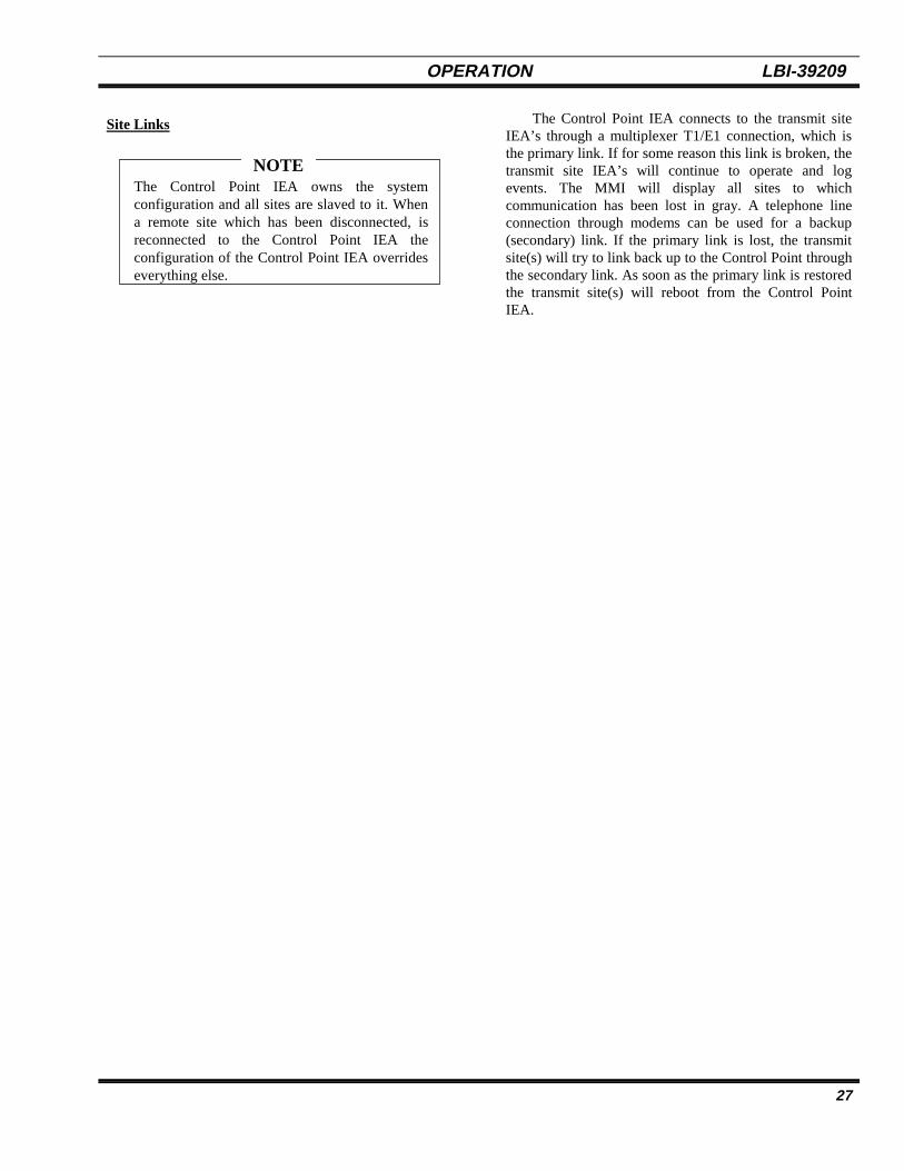
Selecting an individual antenna, such as Antenna #1,from the Tree View, then the Fwd Power tab from theProperties View, displays a graph as shown in Figure 20.This graph provides a continuous indication of theforward power (in watts) for the selected antenna.Selecting the Rev Power tab from the Properties View,displays a graph as shown in Figure 21. This graphprovides a continuous indication of the reverse power (inwatts) for the selected antenna.
Figure 17 - Power Measurements Data

OPERATION LBI-39209
25
Figure 18 - Channel Power Summary
Figure 19 - RF Power Summary to Antennas
LBI-39209 OPERATION
26
Figure 20 - Real Time Forward Antenna Power
Figure 21 - Real Time Reverse Antenna Power
OPERATION LBI-39209
27
Site Links
The Control Point IEA owns the systemconfiguration and all sites are slaved to it. Whena remote site which has been disconnected, isreconnected to the Control Point IEA theconfiguration of the Control Point IEA overrideseverything else.
NOTE
The Control Point IEA connects to the transmit siteIEA’s through a multiplexer T1/E1 connection, which isthe primary link. If for some reason this link is broken, thetransmit site IEA’s will continue to operate and logevents. The MMI will display all sites to whichcommunication has been lost in gray. A telephone lineconnection through modems can be used for a backup(secondary) link. If the primary link is lost, the transmitsite(s) will try to link back up to the Control Point throughthe secondary link. As soon as the primary link is restoredthe transmit site(s) will reboot from the Control PointIEA.

LBI-39209 CONFIGURATION
28
CONFIGURATION
Before configuring the IEA, consult the appropriatedocumentation to determine the radio systemconfiguration.
This section assumes the operator has masteredbasic computer skills and terminology.
NOTE
EXTENDED NETWORK
To add an Extended Network, with the mouse, clickon the appropriate button in the Equipment Palette forAdd Extended Network. This starts the Add HardwareWizard (See Figure 22). Continue as directed in Step 1
through Step 5 (Figures 22 through 26). Figure 27 showsan MMI screen with an Extended Network added.
Step 1 - Identifies an Extended Network is what isbeing added to the IEA.
Step 2- Asks how many Extended Network are to beadded (1-99).
Step 3 - Asks for a description of the network. Userenters name of Extended Network in the Descriptionbox (i.e. Extended Network #1).
Step 4 - Asks for a confirmation of the informationentered.
Step 5 - Finishes the process.
Figure 22 - Add Hardware Wizard (Step 1)
Figure 23 - Add Hardware Wizard (Step 2)
Figure 24 - Description (Step 3)
Figure 25 - Confirm (Step 4)

CONFIGURATION LBI-39209
29
Figure 26 - Finish (Step 5)
Figure 27 - MMI Screen with Extended Network Added
LBI-39209 CONFIGURATION
30
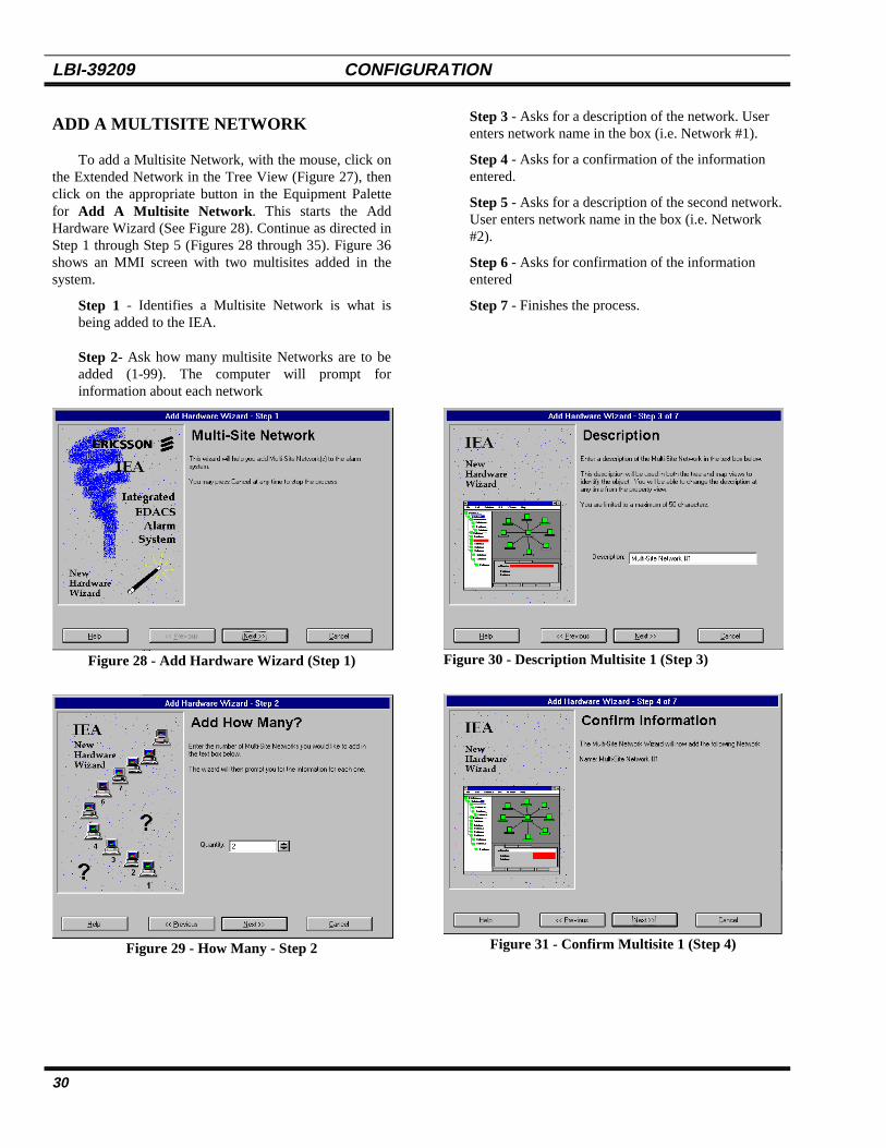
ADD A MULTISITE NETWORK
To add a Multisite Network, with the mouse, click onthe Extended Network in the Tree View (Figure 27), thenclick on the appropriate button in the Equipment Palettefor Add A Multisite Network . This starts the AddHardware Wizard (See Figure 28). Continue as directed inStep 1 through Step 5 (Figures 28 through 35). Figure 36shows an MMI screen with two multisites added in thesystem.
Step 1 - Identifies a Multisite Network is what isbeing added to the IEA.
Step 2- Ask how many multisite Networks are to beadded (1-99). The computer will prompt forinformation about each network
Step 3 - Asks for a description of the network. Userenters network name in the box (i.e. Network #1).
Step 4 - Asks for a confirmation of the informationentered.
Step 5 - Asks for a description of the second network.User enters network name in the box (i.e. Network#2).
Step 6 - Asks for confirmation of the informationentered
Step 7 - Finishes the process.
Figure 28 - Add Hardware Wizard (Step 1)
Figure 29 - How Many - Step 2
Figure 30 - Description Multisite 1 (Step 3)
Figure 31 - Confirm Multisite 1 (Step 4)

CONFIGURATION LBI-39209
31
Figure 32- Description Multisite 2 (Step 5)
Figure 33- Confirm Multisite 2 (Step 6)
Figure 34 - Finish (Step 7)

LBI-39209 CONFIGURATION
32
Figure 35 - MMI Screen with Multisite Network

CONFIGURATION LBI-39209
33
EDACS SYSTEM
To add an EDACS System, with the mouse, click onthe Multisite Network in the Tree View (Figure 35), thenclick on the appropriate button in the Equipment Palettefor Add An EDACS System. This starts the AddHardware Wizard (See Figure 36). Continue as directed inStep 1 through Step 6 (Figures 36 through 41). Figure 42shows an MMI screen with an EDACS System.
Step 1 - Identifies an EDACS System is what is beingadded to the IEA.
Step 2- Asks how many EDACS Systems are to beadded (1-99). The computer will prompt forinformation about each site
Step 3 - Asks for a description of the EDACSSystem. User enters a name for the system (i.e.EDACS System #1).
Step 4 - Asks for a confirmation of the informationentered.
Step 5 - Finishes the process.
Figure 36 - EDACS System (Step 1)
Figure 37 - Add Systems (Step 2)
Figure 38 - System Type (Step 3)
Figure 39 - Description (Step 4)

LBI-39209 CONFIGURATION
34
Figure 40 - Confirm (Step 5) Figure 41 - Finish (Step 6)
Figure 42 - EDACS System

CONFIGURATION LBI-39209
35
EDACS SITE
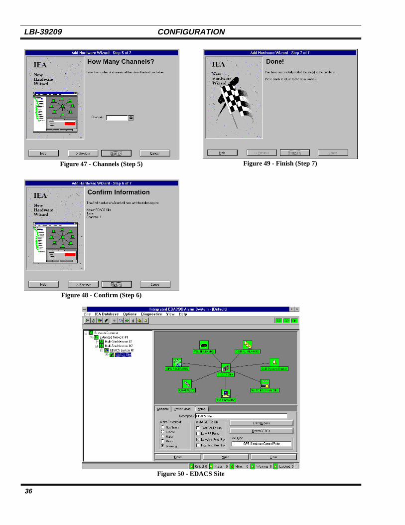
To add an EDACS Site, with the mouse, click on theEDACS System in the Tree View (Figure 42), then clickon the appropriate button in the Equipment Palette forAdd An EDACS Site. This starts the Add HardwareWizard (See Figure 43). Continue as directed in Step 1through Step 7 (Figures 43 through 49). Figure 50 showsan MMI screen with an EDACS site.
Step 1 - Identifies an EDACS Site is what is beingadded to the IEA.
Step 2- Asks how many EDACS Sites are to beadded. The computer will prompt for informationabout each site.
Step 3 - Asks for a description of the Site. The userenters a name in the box (i.e. EDACS Site #1).
Step 4 - Asks for a confirmation of the informationentered.
Step 5 - Finishes the process.
Figure 43 - EDACS Site (Step 1)
Figure 44 - How Many - (Step 2)
Figure 45 - Type Site (Step 3)
Figure 46 - Description (Step 4)
LBI-39209 CONFIGURATION
36
Figure 47 - Channels (Step 5)
Figure 48 - Confirm (Step 6)
Figure 49 - Finish (Step 7)
Figure 50 - EDACS Site

CONFIGURATION LBI-39209
37
ADDITION OF OTHER DEVICES
At this point, using the first set of icons on theEquipment Palette, the basic communication system hasbeen added to the EIA. The second set of icons addsadditional:
• Channels• GPS Receivers• Multiplexer• Antennas• Digital Alarm Groups• Digital Input Alarms
These items can only be added at locations thatwill accept them. The program displays amessage informing the operator when an itemcannot be added.
NOTE
If the tree is expanded from the EDACS Site shownin Figure 50, the equipment shown in the map view isshown in the tree view (see Figure 51).
Figure 51 - Other Devices
Each of these items can be further expanded by clickingwith the mouse on the plus (+) box to the left of the item.For example, CHANNELS (see Figure 52).
Figure 52 - CHANNELS
Figure 52 shows that there are three channels assignedto the EDACS Site (Control Point). The map view shownin Figure 53 also shows a connection of three channels.
Figure 53 - Map View
When choosing to add a device to the database thefollowing message is displayed.
If you enter yes all functions of the alarm system aresuspended. A message at the bottom left-hand side of thescreen says ALARM SYSTEM SUSPENDED. Once thenew information has been entered to restart the operation,select File then Resume Operation.
ADD A CHANNEL
Other channels can be added to the EDACS Site or toCHANNELS. To add a channel, select EDACS Site orCHANNELS from the Tree View, then select Add AChannel from the Equipment Palette (Figure 54).
Figure 54 - Add A Channel Icon
This starts Add Hardware Wizard (Step 1 ) for addingchannels (see Figure 55). Continue as directed in Step 1through step 5 (Figures 55 though 61) Figure 62 shows theEDACS Site with 5 channels. In this example twochannels are added. Otherwise the process would be only5 steps.
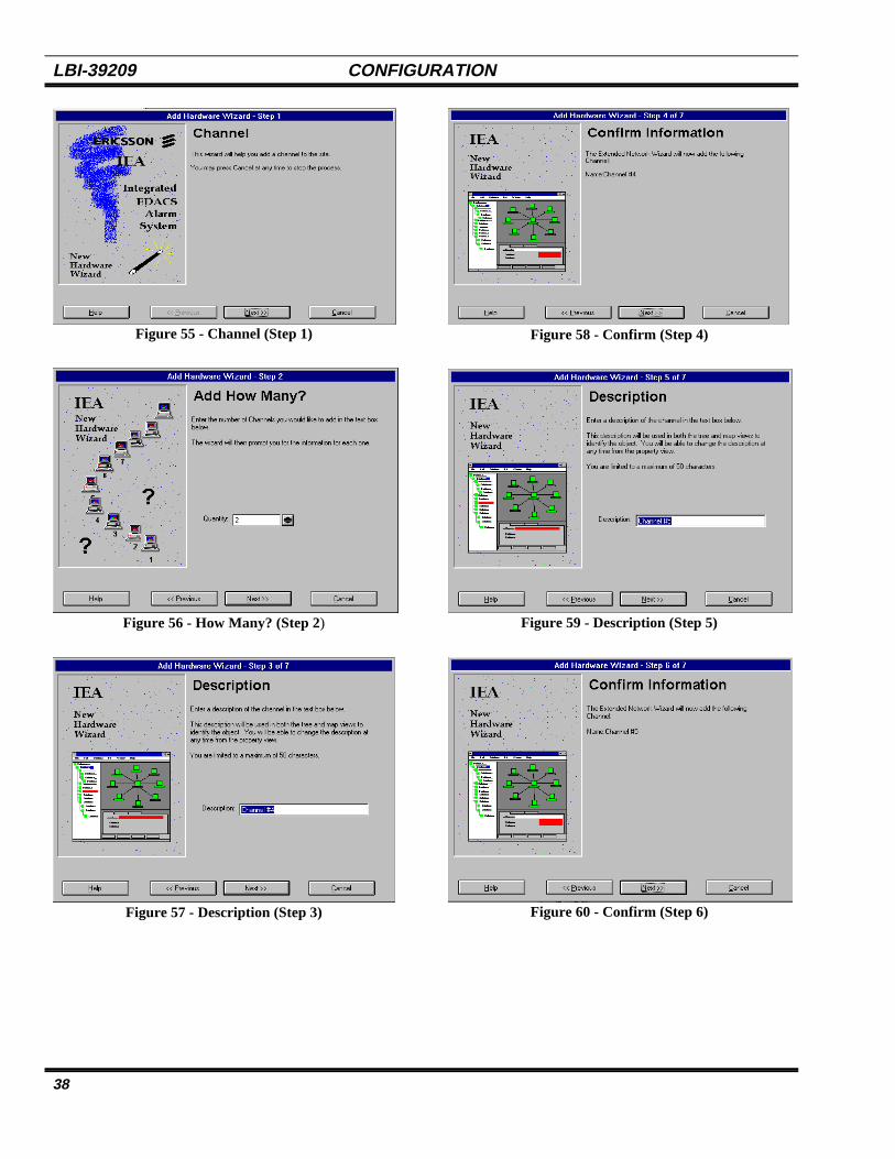
LBI-39209 CONFIGURATION
38
Figure 55 - Channel (Step 1)
Figure 56 - How Many? (Step 2)
Figure 57 - Description (Step 3)
Figure 58 - Confirm (Step 4)
Figure 59 - Description (Step 5)
Figure 60 - Confirm (Step 6)

CONFIGURATION LBI-39209
39
Figure 61 - Finish (Step 7)
Figure 62 - CHANNELS with 5 Channels
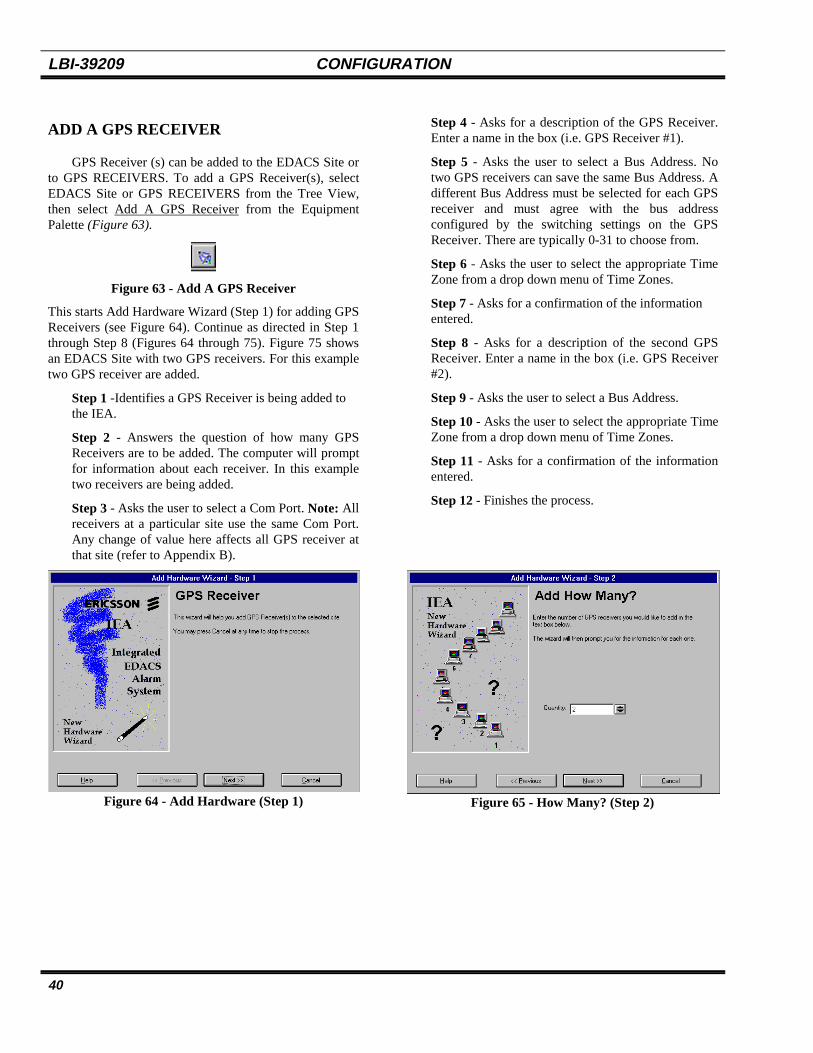
LBI-39209 CONFIGURATION
40
ADD A GPS RECEIVER
GPS Receiver (s) can be added to the EDACS Site orto GPS RECEIVERS. To add a GPS Receiver(s), selectEDACS Site or GPS RECEIVERS from the Tree View,then select Add A GPS Receiver from the EquipmentPalette (Figure 63).
Figure 63 - Add A GPS Receiver
This starts Add Hardware Wizard (Step 1) for adding GPSReceivers (see Figure 64). Continue as directed in Step 1through Step 8 (Figures 64 through 75). Figure 75 showsan EDACS Site with two GPS receivers. For this exampletwo GPS receiver are added.
Step 1 -Identifies a GPS Receiver is being added tothe IEA.
Step 2 - Answers the question of how many GPSReceivers are to be added. The computer will promptfor information about each receiver. In this exampletwo receivers are being added.
Step 3 - Asks the user to select a Com Port. Note: Allreceivers at a particular site use the same Com Port.Any change of value here affects all GPS receiver atthat site (refer to Appendix B).
Step 4 - Asks for a description of the GPS Receiver.Enter a name in the box (i.e. GPS Receiver #1).
Step 5 - Asks the user to select a Bus Address. Notwo GPS receivers can save the same Bus Address. Adifferent Bus Address must be selected for each GPSreceiver and must agree with the bus addressconfigured by the switching settings on the GPSReceiver. There are typically 0-31 to choose from.
Step 6 - Asks the user to select the appropriate TimeZone from a drop down menu of Time Zones.
Step 7 - Asks for a confirmation of the informationentered.
Step 8 - Asks for a description of the second GPSReceiver. Enter a name in the box (i.e. GPS Receiver#2).
Step 9 - Asks the user to select a Bus Address.
Step 10 - Asks the user to select the appropriate TimeZone from a drop down menu of Time Zones.
Step 11 - Asks for a confirmation of the informationentered.
Step 12 - Finishes the process.
Figure 64 - Add Hardware (Step 1) Figure 65 - How Many? (Step 2)
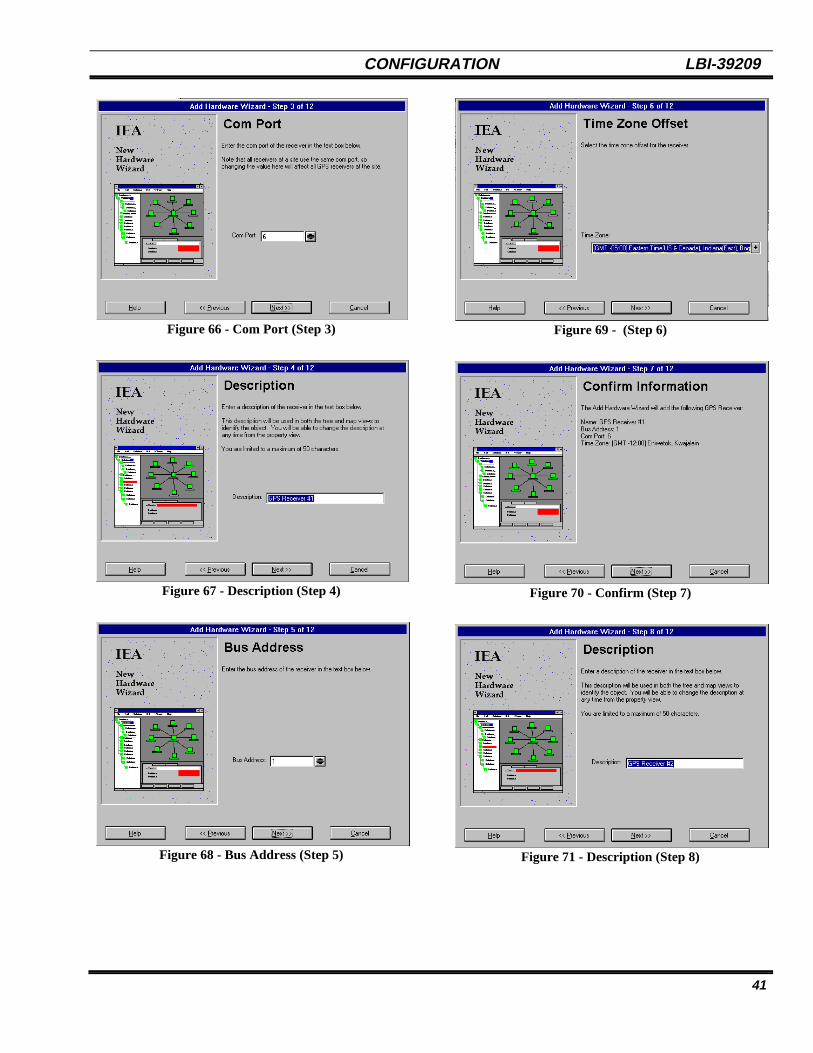
CONFIGURATION LBI-39209
41
Figure 66 - Com Port (Step 3)
Figure 67 - Description (Step 4)
Figure 68 - Bus Address (Step 5)
Figure 69 - (Step 6)
Figure 70 - Confirm (Step 7)
Figure 71 - Description (Step 8)

LBI-39209 CONFIGURATION
42
Figure 72 - Bus Address (Step 9)
Figure 73 - Time Zone Offset (Step 10)
Figure 74 - Confirm (Step 11)
Figure 75 - Finish (Step 12)
Figure 76 - EDACS Site with 2 GPS Receivers
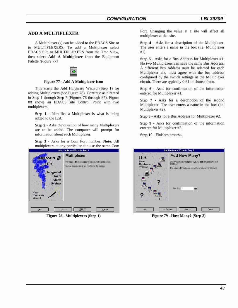
CONFIGURATION LBI-39209
43
ADD A MULTIPLEXER
A Multiplexer (s) can be added to the EDACS Site orto MULTIPLEXERS. To add a Multiplexer selectEDACS Site or MULTIPLEXERS from the Tree View,then select Add A Multiplexer from the EquipmentPalette (Figure 77).
Figure 77 - Add A Multiplexer Icon
This starts the Add Hardware Wizard (Step 1) foradding Multiplexers (see Figure 78). Continue as directedin Step 1 through Step 7 (Figures 78 through 87). Figure88 shows an EDACS site Control Point with twomultiplexers.
Step 1 - Identifies a Multiplexer is what is beingadded to the IEA.
Step 2 - Asks the question of how many Multiplexersare to be added. The computer will prompt forinformation about each Multiplexer.
Step 3 - Asks for a Com Port number. Note: Allmultiplexers at any particular site use the same Com
Port. Changing the value at a site will affect allmultiplexer at that site.
Step 4 - Asks for a description of the Multiplexer.The user enters a name in the box (i.e. Multiplexer#1).
Step 5 - Asks for a Bus Address for Multiplexer #1.No two Multiplexers can save the same Bus Address.A different Bus Address must be selected for eachMultiplexer and must agree with the bus addressconfigured by the switch settings in the Multiplexercircuit. There are typically 0-31 to choose from.
Step 6 - Asks for confirmation of the informationentered for Multiplexer #1.
Step 7 - Asks for a description of the secondMultiplexer. The user enters a name in the box (i.e.Multiplexer #2).
Step 8 - Asks for a Bus Address for Multiplexer #2.
Step 9 - Asks for confirmation of the informationentered for Multiplexer #2.
Step 10 - Finishes process.
Figure 78 - Multiplexers (Step 1) Figure 79 - How Many? (Step 2)

LBI-39209 CONFIGURATION
44
Figure 80 - Com Port (Step 3)
Figure 81 - Description (Step 4)
Figure 82 - Bus Address (Step 5)
Figure 83 - Confirm (Step 6)
Figure 84 - Description (Step 7)
Figure 85 - Bus Address (Step 8)
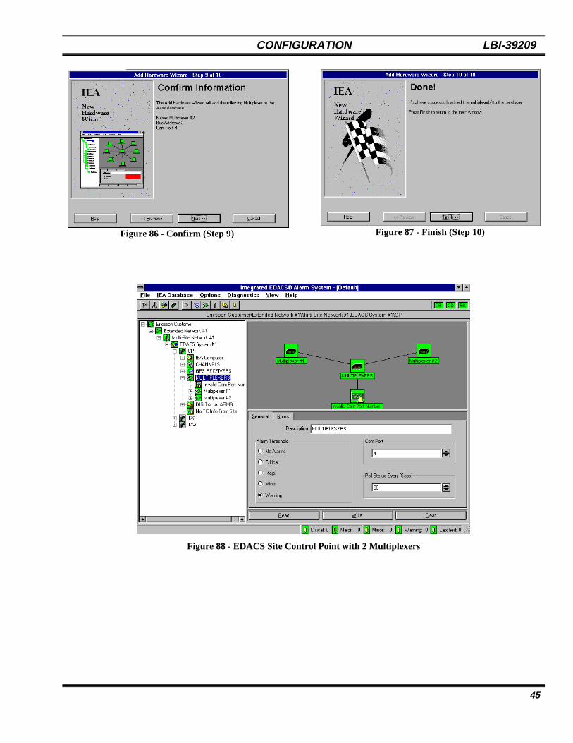
CONFIGURATION LBI-39209
45
Figure 86 - Confirm (Step 9) Figure 87 - Finish (Step 10)
Figure 88 - EDACS Site Control Point with 2 Multiplexers
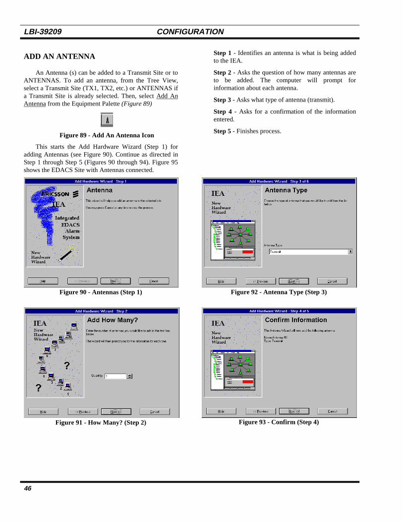
LBI-39209 CONFIGURATION
46
ADD AN ANTENNA
An Antenna (s) can be added to a Transmit Site or toANTENNAS. To add an antenna, from the Tree View,select a Transmit Site (TX1, TX2, etc.) or ANTENNAS ifa Transmit Site is already selected. Then, select Add AnAntenna from the Equipment Palette (Figure 89)
Figure 89 - Add An Antenna Icon
This starts the Add Hardware Wizard (Step 1) foradding Antennas (see Figure 90). Continue as directed inStep 1 through Step 5 (Figures 90 through 94). Figure 95shows the EDACS Site with Antennas connected.
Step 1 - Identifies an antenna is what is being addedto the IEA.
Step 2 - Asks the question of how many antennas areto be added. The computer will prompt forinformation about each antenna.
Step 3 - Asks what type of antenna (transmit).
Step 4 - Asks for a confirmation of the informationentered.
Step 5 - Finishes process.
Figure 90 - Antennas (Step 1)
Figure 91 - How Many? (Step 2)
Figure 92 - Antenna Type (Step 3)
Figure 93 - Confirm (Step 4)

CONFIGURATION LBI-39209
47
Figure 94 - Finish (Step 5)
Figure 95 - EDACS Transmit Site with 2 Antennas

LBI-39209 CONFIGURATION
48
ADD A DIGITAL ALARM GROUP
Digital Alarm Groups provide a way to organize themany user-configurable digital alarms that the IEA systemsupports. The digital I/O board in the alarm systemprovides an expandable number of inputs/outputs for useby the customer. A majority of these alarms are customerdefined and can be changed at their discretion. Groups areused to organize the large number of available inputs intosmaller, easier to manage, groups such as door alarms,environment, etc. Individual alarms are added within eachgroup.
Digital Alarm Groups can be added to EDACS Siteor to DIGITAL ALARMS. To add a Digital AlarmGroup, select EDACS Site or DIGITAL ALARMS fromthe Tree View, then select Add A Digital Alarm Groupfrom the Equipment Palette (Figure 96).
Figure 96 - Add A Digital Alarm Group Icon
This starts Add Hardware Wizard (Step 1) for addingDigital Alarm Groups (See Figure 98) Continue asdirected in Step 1 through Step 5 (Figures 97 through101). Figure 102 shows the EDACS Site with DigitalAlarms
Step 1 - Identifies a Digital Alarm Group is what isbeing added to the IEA.
Step 2 - Ask the question of how many groups are tobe added. The computer will prompt for informationabout each group.
Step 3 - Asks for a description of the group. The userenters a name for the group (i.e. Function Group #1).
Step 4 - Asks for confirmation of the informationentered.
Step 5 - Finishes the process.
.
Figure 97 - GP Digital I/O Group (Step 1)
Figure 98 - Add How Many? (Step 2)
Figure 99 - Description (Step 3)
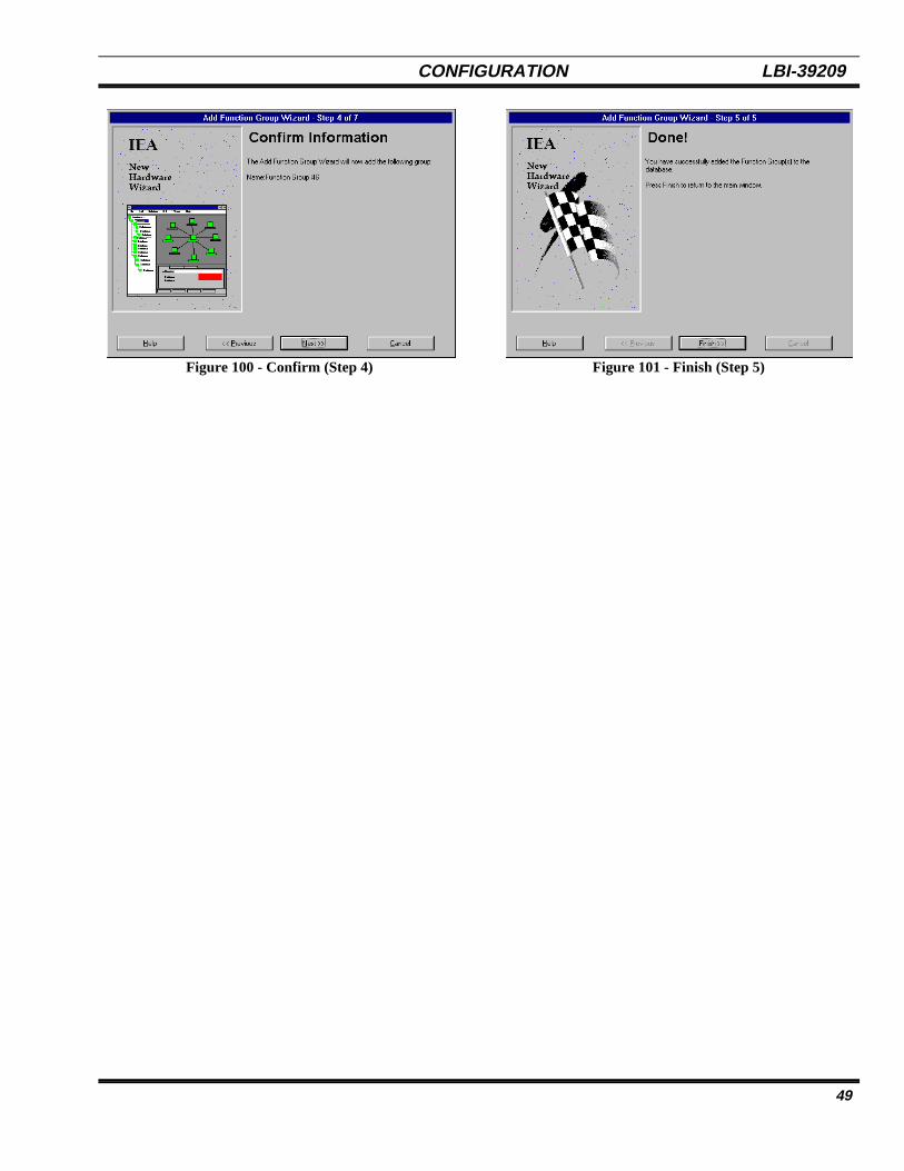
CONFIGURATION LBI-39209
49
Figure 100 - Confirm (Step 4) Figure 101 - Finish (Step 5)
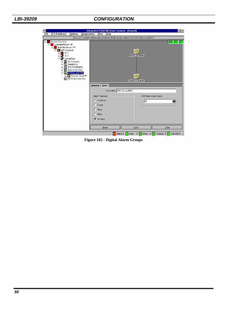
LBI-39209 CONFIGURATION
50
Figure 102 - Digital Alarm Groups

CONFIGURATION LBI-39209
51
ADD A DIGITAL INPUT ALARM
A Digital Input Alarm can be added to EDACS Siteor to DIGITAL ALARMS. To add a Digital Alarm, selectEDACS Site or DIGITAL ALARMS from the Tree View,then select Add A Digital Input Alarm from theEquipment Palette (Figure 103).
Figure 103 - Add A Digital Input Alarm Icon
This starts Add Hardware Wizard (Step 1) for addinga Digital Input Alarm (Figure 104). Continue as directedin Step 1 through Step 13 (Figures 104 through 116).With this example, two digital alarms are added
Step 1 - Identifies a Digital Input Alarm is what is beingadded to the IEA.
Step 2 - Asks the question of how many Digital InputAlarms are to be added. The computer will prompt forinformation about each alarm.
Step 3 - Asks for a description of the alarm. The userenters a name in the box for the alarm (i.e. Point #5).
Step 4 - Asks the user to select from a menu the boardcontaining the input to be added (General Purpose DigitalI/O Board).
Step 5 - Asks the user to choose an input point number tobe added from a list. The list will only show the pointnumber that are available (refer to Appendix A).
Step 6 - Asks the user to select the polarity of the I/Opoint from a menu (This defines the active state of thealarm).
The user defined I/O point must be electricallycompatible with the customer’s equipment, e.g.,the polarity and signal routing must be consistentwith the wizard selection. Refer to theappropriate system wiring diagrams andAppendix A for detailed information.
NOTE
Step 7 - Ask for a confirmation of the information enteredfor Point #5.
Step 8 - Ask for a description of the alarm. The userenters a name in the box for the alarm (i.e. Point #11).
Step 9 - Asks the user to select from a menu the boardcontaining the input to be added (General Purpose DigitalI/O Board).
Step 10 - Asks the user to choose an input point numberto be added from a list. Only the list will only show thepoint numbers that are available (refer to Appendix A).
Step 11 - Asks the user to select the polarity of the I/Opoint from a menu.
Step 12 - Ask for a confirmation of the informationentered for Point #11.
Step 13 - Finishes the process.
Figure 104 - Add Hardware (Step 1) Figure 105 - Add How Many? (Step 2)

LBI-39209 CONFIGURATION
52
Figure 106 - Description (Step 3)
Figure 107 - Select Board (Step 4)
Figure 108 - Port Number (Step 5)
Figure 109 - Polarity (Step 6)
Figure 110 - Confirm (Step 7)
Figure 111 - Description (Step 8)
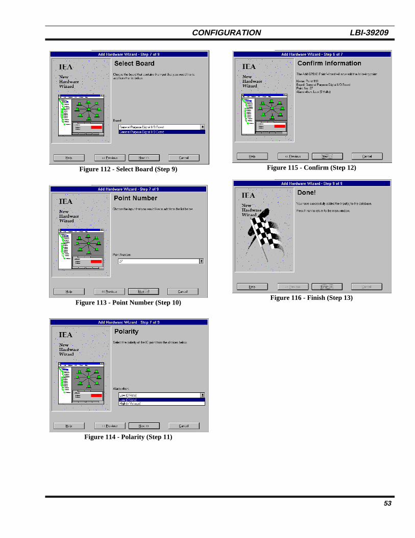
CONFIGURATION LBI-39209
53
Figure 112 - Select Board (Step 9)
Figure 113 - Point Number (Step 10)
Figure 114 - Polarity (Step 11)
Figure 115 - Confirm (Step 12)
Figure 116 - Finish (Step 13)

LBI-39209 CONFIGURATION
54
This page intentionally left blank.

A1
APPENDIX AIEA INPUT/OUTPUT SIGNAL MAPPING

Tab
le A
-1 D
igita
l Int
erru
pt B
oard
Sig
nals
DIG
ITA
LIN
TE
RR
UP
TIS
OLA
TIO
NB
OA
RD
ALA
RM
SIG
NA
LA
LAR
MM
OR
E
DIG
ITA
L IN
TE
RR
UP
T B
OA
RD
I/O D
IRB
OA
RD
TY
PE
XC
ON
NN
AM
EX
CO
NN
XC
ON
N
PT
T C
hann
el 0
1J3
-47
J2-4
7D
T1-
01J1
7-02
J18-
02
PT
T C
hann
el 0
2I
J3-4
5D
J2-4
5D
T1-
02J1
7-04
J18-
04P
TT
Cha
nnel
03
NJ3
-43
IJ2
-43
DT
1-03
J17-
06J1
8-06
PT
T C
hann
el 0
4P
J3-4
1O
J2-4
1D
T1-
04J1
7-08
J18-
08P
TT
Cha
nnel
05
UJ3
-39
DJ2
-39
DT
1-05
J17-
10J1
8-10
PT
T C
hann
el 0
6T
J3-3
7E
J2-3
7D
T1-
06J1
7-12
J18-
12P
TT
Cha
nnel
07
J3-3
5S
J2-3
5D
T1-
07J1
7-14
J18-
14
PT
T C
hann
el 0
8J3
-33
J2-3
3D
T1-
08J1
7-16
J18-
16
PT
T C
hann
el 0
9J3
-31
J2-3
1D
T1-
09J1
7-18
J18-
18
PT
T C
hann
el 1
0I
J3-2
9D
J2-2
9D
T1-
10J1
7-20
J18-
20P
TT
Cha
nnel
11
NJ3
-27
IJ2
-27
DT
1-11
J17-
22J1
8-22
PT
T C
hann
el 1
2P
J3-2
5O
J2-2
5D
T1-
12J1
7-24
J18-
24P
TT
Cha
nnel
13
UJ3
-23
DJ2
-23
DT
1-13
J17-
26J1
8-26
PT
T C
hann
el 1
4T
J3-2
1E
J2-2
1D
T1-
14J1
7-28
J18-
28P
TT
Cha
nnel
15
J3-1
9S
J2-1
9D
T1-
15J1
7-30
J18-
30
PT
T C
hann
el 1
6J3
-17
J2-1
7D
T1-
16J1
7-32
J18-
32
PT
T C
hann
el 1
7J3
-15
J2-1
5D
T1-
17J1
7-34
J18-
34
PT
T C
hann
el 1
8I
J3-1
3D
J2-1
3D
T1-
18J1
7-36
J18-
36P
TT
Cha
nnel
19
NJ3
-11
IJ2
-11
DT
1-19
J17-
38J1
8-38
PT
T C
hann
el 2
0P
J3-0
9O
J2-0
9D
T1-
20J1
7-40
J18-
40P
TT
Cha
nnel
21
UJ3
-07
DJ2
-07
DT
1-21
J17-
42J1
8-42
PT
T C
hann
el 2
2T
J3-0
5E
J2-0
5D
T1-
22J1
7-44
J18-
44P
TT
Cha
nnel
23
J3-0
3S
J2-0
3D
T1-
23J1
7-46
J18-
46
PT
T C
hann
el 2
4J3
-01
J2-0
1D
T1-
24J1
7-48
J18-
48
Con
tinue
d

Con
tinue
dD
IGIT
AL
INT
ER
RU
PT
ISO
LAT
ION
BO
AR
DA
LAR
MS
IGN
AL
ALA
RM
MO
RE
DIG
ITA
L IN
TE
RR
UP
T B
OA
RD
I/O D
IRB
OA
RD
TY
PE
XC
ON
NN
AM
EX
CO
NN
XC
ON
N
L4 R
ecei
ver
Fau
lt C
hann
el 0
1I
J2-4
7D
J3-4
7D
T1-
25J1
6-02
L4 R
ecei
ver
Fau
lt C
hann
el 0
2N
J2-4
5I
J3-4
5D
T1-
26J1
6-04
L4 R
ecei
ver
Fau
lt C
hann
el 0
3P
J2-4
3O
J3-4
3D
T1-
27J1
6-06
L4 R
ecei
ver
Fau
lt C
hann
el 0
4U
J2-4
1D
J3-4
1D
T1-
28J1
6-08
L4 R
ecei
ver
Fau
lt C
hann
el 0
5T
J2-3
9E
J3-3
9D
T1-
29J1
6-10
L4 R
ecei
ver
Fau
lt C
hann
el 0
6J2
-37
SJ3
-37
DT
1-30
J16-
12
L4 R
ecei
ver
Fau
lt C
hann
el 0
7J2
-35
J3-3
5D
T1-
31J1
6-14
L4 R
ecei
ver
Fau
lt C
hann
el 0
8J2
-33
J3-3
3D
T1-
32J1
6-16
L4 R
ecei
ver
Fau
lt C
hann
el 0
9J2
-31
J3-3
1D
T1-
33J1
6-18
L4 R
ecei
ver
Fau
lt C
hann
el 1
0I
J2-2
9D
J3-2
9D
T1-
34J1
6-20
L4 R
ecei
ver
Fau
lt C
hann
el 1
1N
J2-2
7I
J3-2
7D
T1-
35J1
6-22
L4 R
ecei
ver
Fau
lt C
hann
el 1
2P
J2-2
5O
J3-2
5D
T1-
36J1
6-24
L4 R
ecei
ver
Fau
lt C
hann
el 1
3U
J2-2
3D
J3-2
3D
T1-
37J1
6-26
L4 R
ecei
ver
Fau
lt C
hann
el 1
4T
J2-2
1E
J3-2
1D
T1-
38J1
6-28
L4 R
ecei
ver
Fau
lt C
hann
el 1
5J2
-19
SJ3
-19
DT
1-39
J16-
30
L4 R
ecei
ver
Fau
lt C
hann
el 1
6J2
-17
J3-1
7D
T1-
40J1
6-32
L4 R
ecei
ver
Fau
lt C
hann
el 1
7J2
-15
J3-1
5D
T1-
41J1
6-34
L4 R
ecei
ver
Fau
lt C
hann
el 1
8I
J2-1
3D
J3-1
3D
T1-
42J1
6-36
L4 R
ecei
ver
Fau
lt C
hann
el 1
9N
J2-1
1I
J3-1
1D
T1-
43J1
6-38
L4 R
ecei
ver
Fau
lt C
hann
el 2
0P
J2-0
9O
J3-0
9D
T1-
44J1
6-40
L4 R
ecei
ver
Fau
lt C
hann
el 2
1U
J2-0
7D
J3-0
7D
T1-
45J1
6-42
L4 R
ecei
ver
Fau
lt C
hann
el 2
2T
J2-0
5E
J3-0
5D
T1-
46J1
6-44
L4 R
ecei
ver
Fau
lt C
hann
el 2
3J2
-03
SJ3
-03
DT
1-47
J16-
46
L4 R
ecei
ver
Fau
lt C
hann
el 2
4J2
-01
J3-0
1D
T1-
48J1
6-48
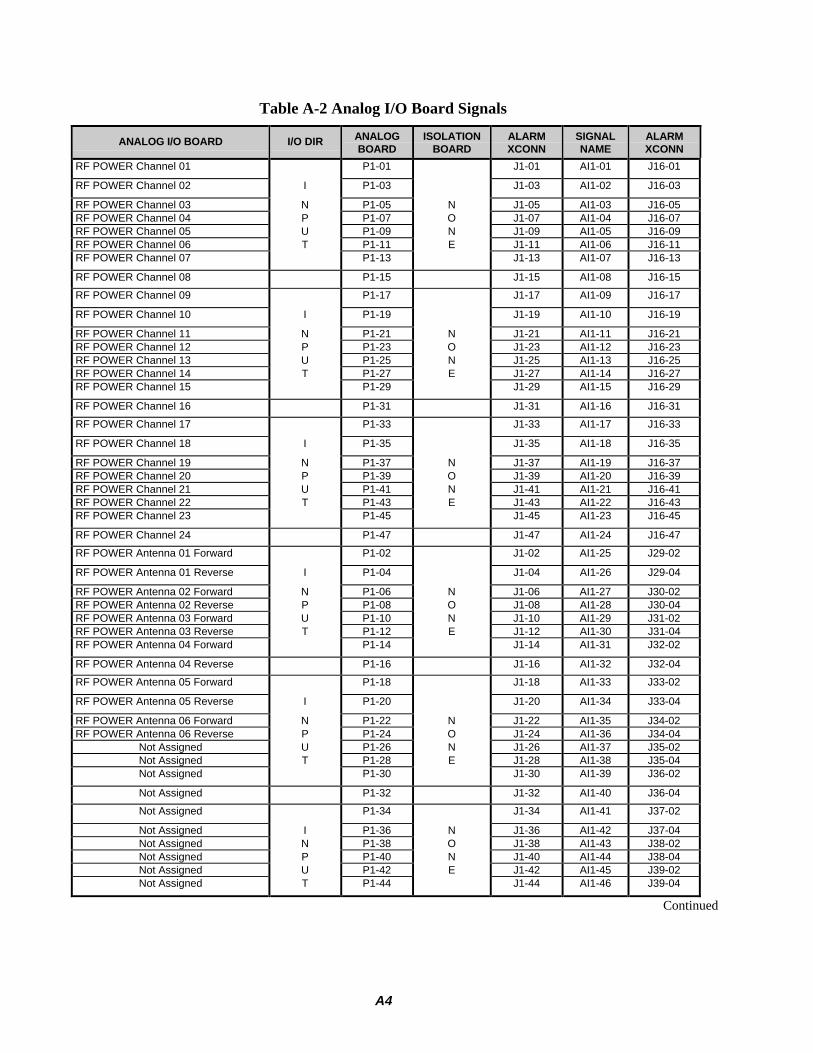
A4
Table A-2 Analog I/O Board Signals
ANALOG I/O BOARD I/O DIR ANALOGBOARD
ISOLATIONBOARD
ALARMXCONN
SIGNALNAME
ALARMXCONN
RF POWER Channel 01 P1-01 J1-01 AI1-01 J16-01
RF POWER Channel 02 I P1-03 J1-03 AI1-02 J16-03
RF POWER Channel 03 N P1-05 N J1-05 AI1-03 J16-05RF POWER Channel 04 P P1-07 O J1-07 AI1-04 J16-07RF POWER Channel 05 U P1-09 N J1-09 AI1-05 J16-09RF POWER Channel 06 T P1-11 E J1-11 AI1-06 J16-11RF POWER Channel 07 P1-13 J1-13 AI1-07 J16-13
RF POWER Channel 08 P1-15 J1-15 AI1-08 J16-15
RF POWER Channel 09 P1-17 J1-17 AI1-09 J16-17
RF POWER Channel 10 I P1-19 J1-19 AI1-10 J16-19
RF POWER Channel 11 N P1-21 N J1-21 AI1-11 J16-21RF POWER Channel 12 P P1-23 O J1-23 AI1-12 J16-23RF POWER Channel 13 U P1-25 N J1-25 AI1-13 J16-25RF POWER Channel 14 T P1-27 E J1-27 AI1-14 J16-27RF POWER Channel 15 P1-29 J1-29 AI1-15 J16-29
RF POWER Channel 16 P1-31 J1-31 AI1-16 J16-31
RF POWER Channel 17 P1-33 J1-33 AI1-17 J16-33
RF POWER Channel 18 I P1-35 J1-35 AI1-18 J16-35
RF POWER Channel 19 N P1-37 N J1-37 AI1-19 J16-37RF POWER Channel 20 P P1-39 O J1-39 AI1-20 J16-39RF POWER Channel 21 U P1-41 N J1-41 AI1-21 J16-41RF POWER Channel 22 T P1-43 E J1-43 AI1-22 J16-43RF POWER Channel 23 P1-45 J1-45 AI1-23 J16-45
RF POWER Channel 24 P1-47 J1-47 AI1-24 J16-47
RF POWER Antenna 01 Forward P1-02 J1-02 AI1-25 J29-02
RF POWER Antenna 01 Reverse I P1-04 J1-04 AI1-26 J29-04
RF POWER Antenna 02 Forward N P1-06 N J1-06 AI1-27 J30-02RF POWER Antenna 02 Reverse P P1-08 O J1-08 AI1-28 J30-04RF POWER Antenna 03 Forward U P1-10 N J1-10 AI1-29 J31-02RF POWER Antenna 03 Reverse T P1-12 E J1-12 AI1-30 J31-04RF POWER Antenna 04 Forward P1-14 J1-14 AI1-31 J32-02
RF POWER Antenna 04 Reverse P1-16 J1-16 AI1-32 J32-04
RF POWER Antenna 05 Forward P1-18 J1-18 AI1-33 J33-02
RF POWER Antenna 05 Reverse I P1-20 J1-20 AI1-34 J33-04
RF POWER Antenna 06 Forward N P1-22 N J1-22 AI1-35 J34-02RF POWER Antenna 06 Reverse P P1-24 O J1-24 AI1-36 J34-04
Not Assigned U P1-26 N J1-26 AI1-37 J35-02Not Assigned T P1-28 E J1-28 AI1-38 J35-04Not Assigned P1-30 J1-30 AI1-39 J36-02
Not Assigned P1-32 J1-32 AI1-40 J36-04
Not Assigned P1-34 J1-34 AI1-41 J37-02
Not Assigned I P1-36 N J1-36 AI1-42 J37-04Not Assigned N P1-38 O J1-38 AI1-43 J38-02Not Assigned P P1-40 N J1-40 AI1-44 J38-04Not Assigned U P1-42 E J1-42 AI1-45 J39-02Not Assigned T P1-44 J1-44 AI1-46 J39-04
Continued

A5
Continued
ANALOG I/O BOARD I/O DIR ANALOGBOARD
ISOLATIONBOARD
ALARMXCONN
SIGNALNAME
ALARMXCONN
Not Assigned P1-46 J1-46 AI1-47 J40-02
Not Assigned P1-48 J1-48 AI1-48 J40-04
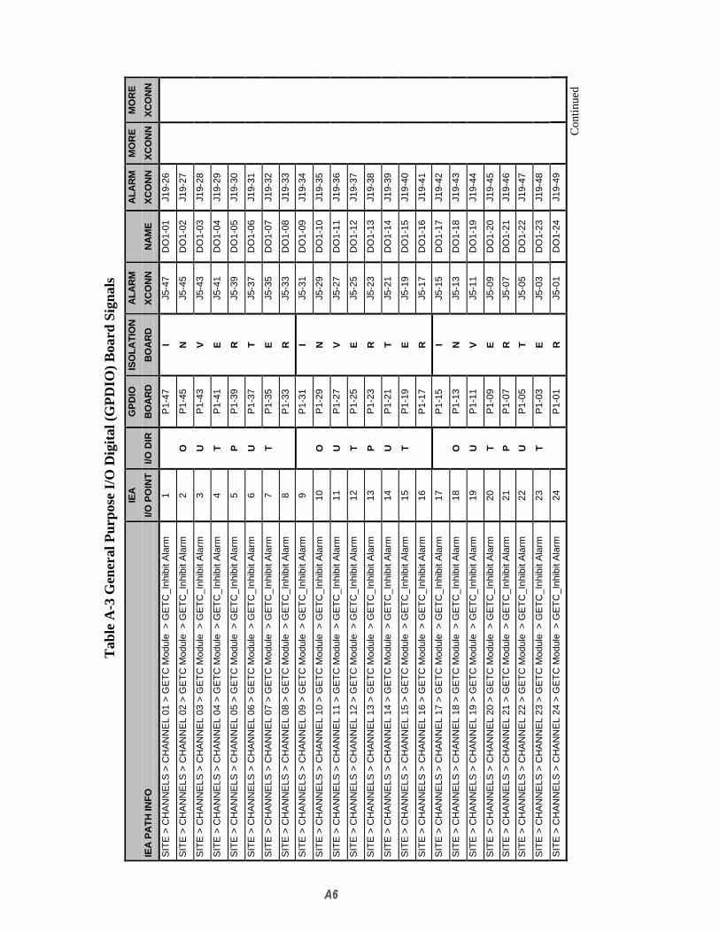
Tab
le A
-3 G
ener
al P
urpo
se I/
O D
igita
l (G
PD
IO)
Boa
rd S
igna
ls
IEA
GP
DIO
ISO
LAT
ION
ALA
RM
ALA
RM
MO
RE
MO
RE
IEA
PA
TH
INF
OI/O
PO
INT
I/O D
IRB
OA
RD
BO
AR
DX
CO
NN
NA
ME
XC
ON
NX
CO
NN
XC
ON
N
SIT
E >
CH
AN
NE
LS >
CH
AN
NE
L 01
> G
ET
C M
odul
e >
GE
TC
_Inh
ibit
Ala
rm1
P1-
47I
J5-4
7D
O1-
01J1
9-26
SIT
E >
CH
AN
NE
LS >
CH
AN
NE
L 02
> G
ET
C M
odul
e >
GE
TC
_Inh
ibit
Ala
rm2
OP
1-45
NJ5
-45
DO
1-02
J19-
27
SIT
E >
CH
AN
NE
LS >
CH
AN
NE
L 03
> G
ET
C M
odul
e >
GE
TC
_Inh
ibit
Ala
rm3
UP
1-43
VJ5
-43
DO
1-03
J19-
28
SIT
E >
CH
AN
NE
LS >
CH
AN
NE
L 04
> G
ET
C M
odul
e >
GE
TC
_Inh
ibit
Ala
rm4
TP
1-41
EJ5
-41
DO
1-04
J19-
29
SIT
E >
CH
AN
NE
LS >
CH
AN
NE
L 05
> G
ET
C M
odul
e >
GE
TC
_Inh
ibit
Ala
rm5
PP
1-39
RJ5
-39
DO
1-05
J19-
30
SIT
E >
CH
AN
NE
LS >
CH
AN
NE
L 06
> G
ET
C M
odul
e >
GE
TC
_Inh
ibit
Ala
rm6
UP
1-37
TJ5
-37
DO
1-06
J19-
31
SIT
E >
CH
AN
NE
LS >
CH
AN
NE
L 07
> G
ET
C M
odul
e >
GE
TC
_Inh
ibit
Ala
rm7
TP
1-35
EJ5
-35
DO
1-07
J19-
32
SIT
E >
CH
AN
NE
LS >
CH
AN
NE
L 08
> G
ET
C M
odul
e >
GE
TC
_Inh
ibit
Ala
rm8
P1-
33R
J5-3
3D
O1-
08J1
9-33
SIT
E >
CH
AN
NE
LS >
CH
AN
NE
L 09
> G
ET
C M
odul
e >
GE
TC
_Inh
ibit
Ala
rm9
P1-
31I
J5-3
1D
O1-
09J1
9-34
SIT
E >
CH
AN
NE
LS >
CH
AN
NE
L 10
> G
ET
C M
odul
e >
GE
TC
_Inh
ibit
Ala
rm10
OP
1-29
NJ5
-29
DO
1-10
J19-
35
SIT
E >
CH
AN
NE
LS >
CH
AN
NE
L 11
> G
ET
C M
odul
e >
GE
TC
_Inh
ibit
Ala
rm11
UP
1-27
VJ5
-27
DO
1-11
J19-
36
SIT
E >
CH
AN
NE
LS >
CH
AN
NE
L 12
> G
ET
C M
odul
e >
GE
TC
_Inh
ibit
Ala
rm12
TP
1-25
EJ5
-25
DO
1-12
J19-
37
SIT
E >
CH
AN
NE
LS >
CH
AN
NE
L 13
> G
ET
C M
odul
e >
GE
TC
_Inh
ibit
Ala
rm13
PP
1-23
RJ5
-23
DO
1-13
J19-
38
SIT
E >
CH
AN
NE
LS >
CH
AN
NE
L 14
> G
ET
C M
odul
e >
GE
TC
_Inh
ibit
Ala
rm14
UP
1-21
TJ5
-21
DO
1-14
J19-
39
SIT
E >
CH
AN
NE
LS >
CH
AN
NE
L 15
> G
ET
C M
odul
e >
GE
TC
_Inh
ibit
Ala
rm15
TP
1-19
EJ5
-19
DO
1-15
J19-
40
SIT
E >
CH
AN
NE
LS >
CH
AN
NE
L 16
> G
ET
C M
odul
e >
GE
TC
_Inh
ibit
Ala
rm16
P1-
17R
J5-1
7D
O1-
16J1
9-41
SIT
E >
CH
AN
NE
LS >
CH
AN
NE
L 17
> G
ET
C M
odul
e >
GE
TC
_Inh
ibit
Ala
rm17
P1-
15I
J5-1
5D
O1-
17J1
9-42
SIT
E >
CH
AN
NE
LS >
CH
AN
NE
L 18
> G
ET
C M
odul
e >
GE
TC
_Inh
ibit
Ala
rm18
OP
1-13
NJ5
-13
DO
1-18
J19-
43
SIT
E >
CH
AN
NE
LS >
CH
AN
NE
L 19
> G
ET
C M
odul
e >
GE
TC
_Inh
ibit
Ala
rm19
UP
1-11
VJ5
-11
DO
1-19
J19-
44
SIT
E >
CH
AN
NE
LS >
CH
AN
NE
L 20
> G
ET
C M
odul
e >
GE
TC
_Inh
ibit
Ala
rm20
TP
1-09
EJ5
-09
DO
1-20
J19-
45
SIT
E >
CH
AN
NE
LS >
CH
AN
NE
L 21
> G
ET
C M
odul
e >
GE
TC
_Inh
ibit
Ala
rm21
PP
1-07
RJ5
-07
DO
1-21
J19-
46
SIT
E >
CH
AN
NE
LS >
CH
AN
NE
L 22
> G
ET
C M
odul
e >
GE
TC
_Inh
ibit
Ala
rm22
UP
1-05
TJ5
-05
DO
1-22
J19-
47
SIT
E >
CH
AN
NE
LS >
CH
AN
NE
L 23
> G
ET
C M
odul
e >
GE
TC
_Inh
ibit
Ala
rm23
TP
1-03
EJ5
-03
DO
1-23
J19-
48
SIT
E >
CH
AN
NE
LS >
CH
AN
NE
L 24
> G
ET
C M
odul
e >
GE
TC
_Inh
ibit
Ala
rm24
P1-
01R
J5-0
1D
O1-
24J1
9-49
Con
tinue
d

Con
tinue
dIE
AG
PD
IOIS
OLA
TIO
NA
LAR
MA
LAR
MM
OR
EM
OR
E
IEA
PA
TH
INF
OIO
PO
INT
I/O D
IRB
OA
RD
BO
AR
DX
CO
NN
NA
ME
XC
ON
NX
CO
NN
XC
ON
N
BY
PA
SS
25P
2-47
J6-4
7D
O2-
01J2
0-26
J48-
02
Una
ssig
ned
26O
P2-
45D
J6-4
5D
O2-
02J2
0-27
J48-
04
Una
ssig
ned
27U
P2-
43I
J6-4
3D
O2-
03J2
0-28
J49-
02
Una
ssig
ned
28T
P2-
41O
J6-4
1D
O2-
04J2
0-29
J49-
04
Una
ssig
ned
29P
P2-
39D
J6-3
9D
O2-
05J2
0-30
J50-
02
Una
ssig
ned
30U
P2-
37E
J6-3
7D
O2-
06J2
0-31
J50-
04
Una
ssig
ned
31T
P2-
35S
J6-3
5D
O2-
07J2
0-32
J51-
02
Una
ssig
ned
32P
2-33
J6-3
3D
O2-
08J2
0-33
J51-
04
GE
TC
Res
et33
P2-
31I
J6-3
1D
O2-
09J2
0-34
J52-
02
Una
ssig
ned
34O
P2-
29N
J6-2
9D
O2-
10J2
0-35
J52-
04
Una
ssig
ned
35U
P2-
27V
J6-2
7D
O2-
11J2
0-36
Una
ssig
ned
36T
P2-
25E
J6-2
5D
O2-
12J2
0-37
Una
ssig
ned
37P
P2-
23R
J6-2
3D
O2-
13J2
0-38
Una
ssig
ned
38U
P2-
21T
J6-2
1D
O2-
14J2
0-39
Una
ssig
ned
39T
P2-
19E
J6-1
9D
O2-
15J2
0-40
Una
ssig
ned
40P
2-17
RJ6
-17
DO
2-16
J20-
41
Una
ssig
ned
41P
2-15
IJ6
-15
DO
2-17
J20-
42
Una
ssig
ned
42O
P2-
13N
J6-1
3D
O2-
18J2
0-43
Una
ssig
ned
43U
P2-
11V
J6-1
1D
O2-
19J2
0-44
Una
ssig
ned
44T
P2-
09E
J6-0
9D
O2-
20J2
0-45
Una
ssig
ned
45P
P2-
07R
J6-0
7D
O2-
21J2
0-46
Una
ssig
ned
46U
P2-
05T
J6-0
5D
O2-
22J2
0-47
Una
ssig
ned
47T
P2-
03E
J6-0
3D
O2-
23J2
0-48
Una
ssig
ned
48P
2-01
RJ6
-01
DO
2-24
J20-
49
Con
tinue
d

Con
tinue
dIE
AG
PD
IOIS
OLA
TIO
NA
LAR
MA
LAR
MM
OR
EM
OR
E
IEA
PA
TH
INF
OIO
PO
INT
I/O D
IRB
OA
RD
BO
AR
DX
CO
NN
NA
ME
XC
ON
NX
CO
NN
XC
ON
N
SIT
E >
DIG
ITA
L A
LAR
MS
> L
SD
Sel
ecto
r M
odul
es >
LS
D S
elec
tor
A A
larm
49P
3-47
J7-4
7D
I1-0
1J2
1-01
SIT
E >
DIG
ITA
L A
LAR
MS
> L
SD
Sel
ecto
r M
odul
es >
LS
D S
elec
tor
B A
larm
50I
P3-
45D
J7-4
5D
I1-0
2J2
1-26
SIT
E >
DIG
ITA
L A
LAR
MS
> L
SD
Sel
ecto
r M
odul
es >
No
Low
Spe
ed D
ata
51N
P3-
43I
J7-4
3D
I1-0
3J2
1-02
SIT
E >
DIG
ITA
L A
LAR
MS
> T
imin
g M
odul
es >
Mod
ule
A F
ault
52P
P3-
41O
J7-4
1D
I1-0
4J2
1-27
SIT
E >
DIG
ITA
L A
LAR
MS
> T
imin
g M
odul
es >
Mod
ule
B F
ault
53U
P3-
39D
J7-3
9D
I1-0
5J2
1-03
SIT
E >
DIG
ITA
L A
LAR
MS
> T
imin
g M
odul
es >
Tim
ing
Mod
ule
Maj
or54
TP
3-37
EJ7
-37
DI1
-06
J21-
28
SIT
E >
DIG
ITA
L A
LAR
MS
> T
imin
g M
odul
es >
FS
L (C
P )
or
LL 1
PP
S(T
X/R
X)
55P
3-35
SJ7
-35
DI1
-07
J21-
04
SIT
E >
DIG
ITA
L A
LAR
MS
> R
esyn
c M
odul
es >
Res
ync
Car
d 1
56P
3-33
J7-3
3D
I1-0
8J2
1-29
SIT
E >
DIG
ITA
L A
LAR
MS
> R
esyn
c M
odul
es >
Res
ync
Car
d 2
57P
3-31
J7-3
1D
I1-0
9J2
1-05
SIT
E >
DIG
ITA
L A
LAR
MS
> R
esyn
c M
odul
es >
Res
ync
Car
d 3
58I
P3-
29D
J7-2
9D
I1-1
0J2
1-30
SIT
E >
DIG
ITA
L A
LAR
MS
> R
esyn
c M
odul
es >
Res
ync
Car
d 4
59N
P3-
27I
J7-2
7D
I1-1
1J2
1-06
SIT
E >
DIG
ITA
L A
LAR
MS
> T
imin
g M
odul
es >
GP
S A
Fau
lt60
PP
3-25
OJ7
-25
DI1
-12
J21-
31
SIT
E >
DIG
ITA
L A
LAR
MS
> T
imin
g M
odul
es >
GP
S B
Fau
lt61
UP
3-23
DJ7
-23
DI1
-13
J21-
07
SIT
E >
DIG
ITA
L A
LAR
MS
> L
SD
Sel
ecto
r M
odul
es >
LS
D S
elec
tor
A A
ctiv
e62
TP
3-21
EJ7
-21
DI1
-14
J21-
32
SIT
E >
DIG
ITA
L A
LAR
MS
> L
SD
Sel
ecto
r M
odul
es >
LS
D S
elec
tor
B A
ctiv
e63
P3-
19S
J7-1
9D
I1-1
5J2
1-08
SIT
E >
DIG
ITA
L A
LAR
MS
> T
imin
g M
odul
es >
Mod
ule
A A
ctiv
e64
P3-
17J7
-17
DI1
-16
J21-
33
SIT
E >
DIG
ITA
L A
LAR
MS
> T
imin
g M
odul
es >
Mod
ule
B A
ctiv
e65
P3-
15J7
-15
DI1
-17
J21-
09
Una
ssig
ned
66I
P3-
13D
J7-1
3D
I1-1
8J2
1-34
Una
ssig
ned
67N
P3-
11I
J7-1
1D
I1-1
9J2
1-10
Una
ssig
ned
68P
P3-
09O
J7-0
9D
I1-2
0J2
1-35
Una
ssig
ned
69U
P3-
07D
J7-0
7D
I1-2
1J2
1-11
SIT
E >
DIG
ITA
L A
LAR
MS
> G
PS
Dis
t Mod
ule
> M
ajor
Ala
rm70
TP
3-05
EJ7
-05
DI1
-22
J21-
36
SIT
E >
DIG
ITA
L A
LAR
MS
> G
PS
Dis
t Mod
ule
> M
inor
Ala
rm71
P3-
03S
J7-0
3D
I1-2
3J2
1-12
SIT
E >
DIG
ITA
L A
LAR
MS
> P
ower
Sup
ply
Ala
rms
> S
im E
quip
. Rac
k P
S72
P3-
01J7
-01
DI1
-24
J21-
37
Con
tinue
d
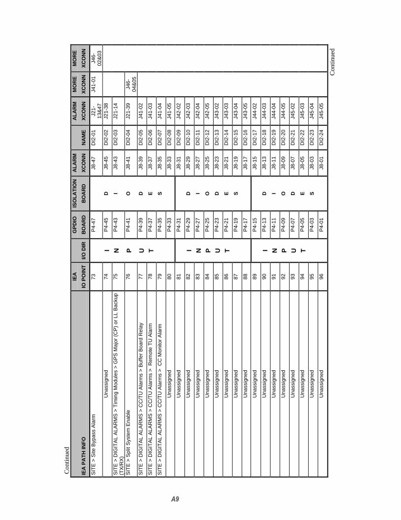
Con
tinue
dIE
AG
PD
IOIS
OLA
TIO
NA
LAR
MA
LAR
MM
OR
EM
OR
E
IEA
PA
TH
INF
OIO
PO
INT
I/O D
IRB
OA
RD
BO
AR
DX
CO
NN
NA
ME
XC
ON
NX
CO
NN
XC
ON
N
SIT
E >
Site
Byp
ass
Ala
rm73
P4-
47J8
-47
DI2
-01
J21-
13&
47J4
1-01
J46-
02&
03U
nass
igne
d74
IP
4-45
DJ8
-45
DI2
-02
J21-
38
SIT
E >
DIG
ITA
L A
LAR
MS
> T
imin
g M
odul
es >
GP
S M
ajor
(C
P)
or L
L B
acku
p(T
X/R
X)
75N
P4-
43I
J8-4
3D
I2-0
3J2
1-14
SIT
E >
Spl
it S
yste
m E
nabl
e76
PP
4-41
OJ8
-41
DI2
-04
J21-
39J4
6-04
&05
SIT
E >
DIG
ITA
L A
LAR
MS
> C
C/T
U A
larm
s >
Buf
fer
Boa
rd R
elay
77U
P4-
39D
J8-3
9D
I2-0
5J4
1-02
SIT
E >
DIG
ITA
L A
LAR
MS
> C
C/T
U A
larm
s >
Rem
ote
TU
Ala
rm78
TP
4-37
EJ8
-37
DI2
-06
J41-
03
SIT
E >
DIG
ITA
L A
LAR
MS
> C
C/T
U A
larm
s >
CC
Mon
itor
Ala
rm79
P4-
35S
J8-3
5D
I2-0
7J4
1-04
Una
ssig
ned
80P
4-33
J8-3
3D
I2-0
8J4
1-05
Una
ssig
ned
81P
4-31
J8-3
1D
I2-0
9J4
2-02
Una
ssig
ned
82I
P4-
29D
J8-2
9D
I2-1
0J4
2-03
Una
ssig
ned
83N
P4-
27I
J8-2
7D
I2-1
1J4
2-04
Una
ssig
ned
84P
P4-
25O
J8-2
5D
I2-1
2J4
2-05
Una
ssig
ned
85U
P4-
23D
J8-2
3D
I2-1
3J4
3-02
Una
ssig
ned
86T
P4-
21E
J8-2
1D
I2-1
4J4
3-03
Una
ssig
ned
87P
4-19
SJ8
-19
DI2
-15
J43-
04
Una
ssig
ned
88P
4-17
J8-1
7D
I2-1
6J4
3-05
Una
ssig
ned
89P
4-15
J8-1
5D
I2-1
7J4
4-02
Una
ssig
ned
90I
P4-
13D
J8-1
3D
I2-1
8J4
4-03
Una
ssig
ned
91N
P4-
11I
J8-1
1D
I2-1
9J4
4-04
Una
ssig
ned
92P
P4-
09O
J8-0
9D
I2-2
0J4
4-05
Una
ssig
ned
93U
P4-
07D
J8-0
7D
I2-2
1J4
5-02
Una
ssig
ned
94T
P4-
05E
J8-0
5D
I2-2
2J4
5-03
Una
ssig
ned
95P
4-03
SJ8
-03
DI2
-23
J45-
04
Una
ssig
ned
96P
4-01
J8-0
1D
I2-2
4J4
5-05
Con
tinue
d

Con
tinue
dIE
AG
PD
IOIS
OLA
TIO
NA
LAR
MA
LAR
MM
OR
EM
OR
E
IEA
PA
TH
INF
OIO
PO
INT
I/O D
IRB
OA
RD
BO
AR
DX
CO
NN
NA
ME
XC
ON
NX
CO
NN
XC
ON
N
Una
ssig
ned
97P
5-47
J9-4
7D
I3-0
1J2
2-26
Una
ssig
ned
98C
P5-
45J9
-45
DI3
-02
J22-
27
Una
ssig
ned
99H
P5-
43N
J9-4
3D
I3-0
3J2
2-28
Una
ssig
ned
100
OP
5-41
OJ9
-41
DI3
-04
J22-
29
Una
ssig
ned
101
IP
5-39
NJ9
-39
DI3
-05
J22-
30
Una
ssig
ned
102
CP
5-37
EJ9
-37
DI3
-06
J22-
31
Una
ssig
ned
103
EP
5-35
J9-3
5D
I3-0
7J2
2-32
Una
ssig
ned
104
P5-
33J9
-33
DI3
-08
J22-
33
Una
ssig
ned
105
P5-
31J9
-31
DI3
-09
J22-
34
Una
ssig
ned
106
CP
5-29
J9-2
9D
I3-1
0J2
2-35
Una
ssig
ned
107
HP
5-27
NJ9
-27
DI3
-11
J22-
36
Una
ssig
ned
108
OP
5-25
OJ9
-25
DI3
-12
J22-
37
Una
ssig
ned
109
IP
5-23
NJ9
-23
DI3
-13
J22-
38
Una
ssig
ned
110
CP
5-21
EJ9
-21
DI3
-14
J22-
39
Una
ssig
ned
111
EP
5-19
J9-1
9D
I3-1
5J2
2-40
Una
ssig
ned
112
P5-
17J9
-17
DI3
-16
J22-
41
Una
ssig
ned
113
P5-
15J9
-15
DI3
-17
J22-
42
Una
ssig
ned
114
CP
5-13
J9-1
3D
I3-1
8J2
2-43
Una
ssig
ned
115
HP
5-11
NJ9
-11
DI3
-19
J22-
44
Una
ssig
ned
116
OP
5-09
OJ9
-09
DI3
-20
J22-
45
Una
ssig
ned
117
IP
5-07
NJ9
-07
DI3
-21
J22-
46
Una
ssig
ned
118
CP
5-05
EJ9
-05
DI3
-22
J22-
47
Una
ssig
ned
119
EP
5-03
J9-0
3D
I3-2
3J2
2-48
Una
ssig
ned
120
P5-
01J9
-01
DI3
-24
J22-
49
Con
tinue
d

Con
tinue
dIE
AG
PD
IOIS
OLA
TIO
NA
LAR
MA
LAR
MM
OR
EM
OR
E
IEA
PA
TH
INF
OIO
PO
INT
I/O D
IRB
OA
RD
BO
AR
DX
CO
NN
NA
ME
XC
ON
NX
CO
NN
XC
ON
N
Una
ssig
ned
121
P6-
47J1
0-47
DI4
-01
J23-
26
Una
ssig
ned
122
CP
6-45
J10-
45D
I4-0
2J2
3-27
Una
ssig
ned
123
HP
6-43
NJ1
0-43
DI4
-03
J23-
28
Una
ssig
ned
124
OP
6-41
OJ1
0-41
DI4
-04
J23-
29
Una
ssig
ned
125
IP
6-39
NJ1
0-39
DI4
-05
J23-
30
Una
ssig
ned
126
CP
6-37
EJ1
0-37
DI4
-06
J23-
31
Una
ssig
ned
127
EP
6-35
J10-
35D
I4-0
7J2
3-32
Una
ssig
ned
128
P6-
33J1
0-33
DI4
-08
J23-
33
Una
ssig
ned
129
P6-
31J1
0-31
DI4
-09
J23-
34
Una
ssig
ned
130
CP
6-29
J10-
29D
I4-1
0J2
3-35
Una
ssig
ned
131
HP
6-27
NJ1
0-27
DI4
-11
J23-
36
Una
ssig
ned
132
OP
6-25
OJ1
0-25
DI4
-12
J23-
37
Una
ssig
ned
133
IP
6-23
NJ1
0-23
DI4
-13
J23-
38
Una
ssig
ned
134
CP
6-21
EJ1
0-21
DI4
-14
J23-
39
Una
ssig
ned
135
EP
6-19
J10-
19D
I4-1
5J2
3-40
Una
ssig
ned
136
P6-
17J1
0-17
DI4
-16
J23-
41
Una
ssig
ned
137
P6-
15J1
0-15
DI4
-17
J23-
42
Una
ssig
ned
138
CP
6-13
J10-
13D
I4-1
8J2
3-43
Una
ssig
ned
139
HP
6-11
NJ1
0-11
DI4
-19
J23-
44
Una
ssig
ned
140
OP
6-09
OJ1
0-09
DI4
-20
J23-
45
Una
ssig
ned
141
IP
6-07
NJ1
0-07
DI4
-21
J23-
46
Una
ssig
ned
142
CP
6-05
EJ1
0-05
DI4
-22
J23-
47
Una
ssig
ned
143
EP
6-03
J10-
03D
I4-2
3J2
3-48
Una
ssig
ned
144
P6-
01J1
0-01
DI4
-24
J23-
49
Con
tinue
d
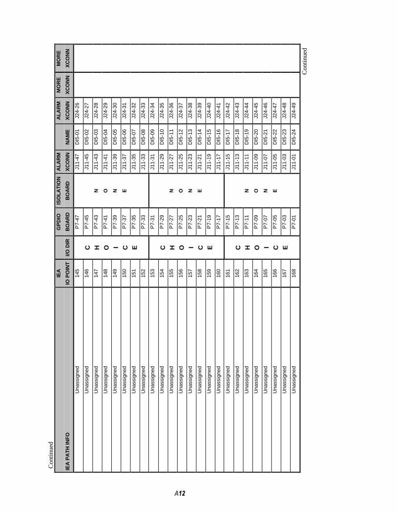
Con
tinue
dIE
AG
PD
IOIS
OLA
TIO
NA
LAR
MA
LAR
MM
OR
EM
OR
E
IEA
PA
TH
INF
OIO
PO
INT
I/O D
IRB
OA
RD
BO
AR
DX
CO
NN
NA
ME
XC
ON
NX
CO
NN
XC
ON
N
Una
ssig
ned
145
P7-
47J1
1-47
DI5
-01
J24-
26
Una
ssig
ned
146
CP
7-45
J11-
45D
I5-0
2J2
4-27
Una
ssig
ned
147
HP
7-43
NJ1
1-43
DI5
-03
J24-
28
Una
ssig
ned
148
OP
7-41
OJ1
1-41
DI5
-04
J24-
29
Una
ssig
ned
149
IP
7-39
NJ1
1-39
DI5
-05
J24-
30
Una
ssig
ned
150
CP
7-37
EJ1
1-37
DI5
-06
J24-
31
Una
ssig
ned
151
EP
7-35
J11-
35D
I5-0
7J2
4-32
Una
ssig
ned
152
P7-
33J1
1-33
DI5
-08
J24-
33
Una
ssig
ned
153
P7-
31J1
1-31
DI5
-09
J24-
34
Una
ssig
ned
154
CP
7-29
J11-
29D
I5-1
0J2
4-35
Una
ssig
ned
155
HP
7-27
NJ1
1-27
DI5
-11
J24-
36
Una
ssig
ned
156
OP
7-25
OJ1
1-25
DI5
-12
J24-
37
Una
ssig
ned
157
IP
7-23
NJ1
1-23
DI5
-13
J24-
38
Una
ssig
ned
158
CP
7-21
EJ1
1-21
DI5
-14
J24-
39
Una
ssig
ned
159
EP
7-19
J11-
19D
I5-1
5J2
4-40
Una
ssig
ned
160
P7-
17J1
1-17
DI5
-16
J24-
41
Una
ssig
ned
161
P7-
15J1
1-15
DI5
-17
J24-
42
Una
ssig
ned
162
CP
7-13
J11-
13D
I5-1
8J2
4-43
Una
ssig
ned
163
HP
7-11
NJ1
1-11
DI5
-19
J24-
44
Una
ssig
ned
164
OP
7-09
OJ1
1-09
DI5
-20
J24-
45
Una
ssig
ned
165
IP
7-07
NJ1
1-07
DI5
-21
J24-
46
Una
ssig
ned
166
CP
7-05
EJ1
1-05
DI5
-22
J24-
47
Una
ssig
ned
167
EP
7-03
J11-
03D
I5-2
3J2
4-48
Una
ssig
ned
168
P7-
01J1
1-01
DI5
-24
J24-
49
Con
tinue
d

Con
tinue
dIE
AG
PD
IOIS
OLA
TIO
NA
LAR
MA
LAR
MM
OR
EM
OR
E
IEA
PA
TH
INF
OIO
PO
INT
I/O D
IRB
OA
RD
BO
AR
DX
CO
NN
NA
ME
XC
ON
NX
CO
NN
XC
ON
N
Una
ssig
ned
169
P8-
47J1
2-47
DI6
-01
J25-
26
Una
ssig
ned
170
CP
8-45
J12-
45D
I6-0
2J2
5-27
Una
ssig
ned
171
HP
8-43
NJ1
2-43
DI6
-03
J25-
28
Una
ssig
ned
172
OP
8-41
OJ1
2-41
DI6
-04
J25-
29
Una
ssig
ned
173
IP
8-39
NJ1
2-39
DI6
-05
J25-
30
Una
ssig
ned
174
CP
8-37
EJ1
2-37
DI6
-06
J25-
31
Una
ssig
ned
175
EP
8-35
J12-
35D
I6-0
7J2
5-32
Una
ssig
ned
176
P8-
33J1
2-33
DI6
-08
J25-
33
Una
ssig
ned
177
P8-
31J1
2-31
DI6
-09
J25-
34
Una
ssig
ned
178
CP
8-29
J12-
29D
I6-1
0J2
5-35
Una
ssig
ned
179
HP
8-27
NJ1
2-27
DI6
-11
J25-
36
Una
ssig
ned
180
OP
8-25
OJ1
2-25
DI6
-12
J25-
37
Una
ssig
ned
181
IP
8-23
NJ1
2-23
DI6
-13
J25-
38
Una
ssig
ned
182
CP
8-21
EJ1
2-21
DI6
-14
J25-
39
Una
ssig
ned
183
EP
8-19
J12-
19D
I6-1
5J2
5-40
Una
ssig
ned
184
P8-
17J1
2-17
DI6
-16
J25-
41
Una
ssig
ned
185
P8-
15J1
2-15
DI6
-17
J25-
42
Una
ssig
ned
186
CP
8-13
J12-
13D
I6-1
8J2
5-43
Una
ssig
ned
187
HP
8-11
NJ1
2-11
DI6
-19
J25-
44
Una
ssig
ned
188
OP
8-09
OJ1
2-09
DI6
-20
J25-
45
Una
ssig
ned
189
IP
8-07
NJ1
2-07
DI6
-21
J25-
46
Una
ssig
ned
190
CP
8-05
EJ1
2-05
DI6
-22
J25-
47
Una
ssig
ned
191
EP
8-03
J12-
03D
I6-2
3J2
5-48
Una
ssig
ned
192
P8-
01J1
2-01
DI6
-24
J25-
49
Con
tinue
d
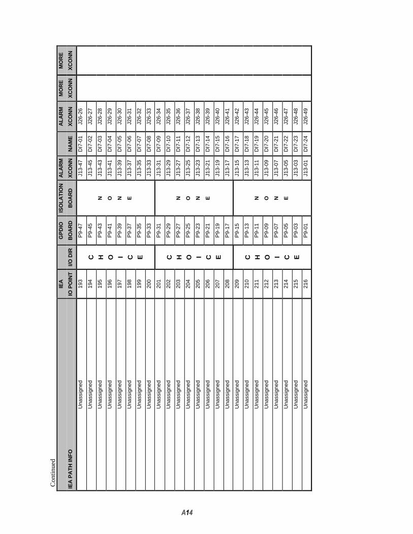
Con
tinue
dIE
AG
PD
IOIS
OLA
TIO
NA
LAR
MA
LAR
MM
OR
EM
OR
E
IEA
PA
TH
INF
OIO
PO
INT
I/O D
IRB
OA
RD
BO
AR
DX
CO
NN
NA
ME
XC
ON
NX
CO
NN
XC
ON
N
Una
ssig
ned
193
P9-
47J1
3-47
DI7
-01
J26-
26
Una
ssig
ned
194
CP
9-45
J13-
45D
I7-0
2J2
6-27
Una
ssig
ned
195
HP
9-43
NJ1
3-43
DI7
-03
J26-
28
Una
ssig
ned
196
OP
9-41
OJ1
3-41
DI7
-04
J26-
29
Una
ssig
ned
197
IP
9-39
NJ1
3-39
DI7
-05
J26-
30
Una
ssig
ned
198
CP
9-37
EJ1
3-37
DI7
-06
J26-
31
Una
ssig
ned
199
EP
9-35
J13-
35D
I7-0
7J2
6-32
Una
ssig
ned
200
P9-
33J1
3-33
DI7
-08
J26-
33
Una
ssig
ned
201
P9-
31J1
3-31
DI7
-09
J26-
34
Una
ssig
ned
202
CP
9-29
J13-
29D
I7-1
0J2
6-35
Una
ssig
ned
203
HP
9-27
NJ1
3-27
DI7
-11
J26-
36
Una
ssig
ned
204
OP
9-25
OJ1
3-25
DI7
-12
J26-
37
Una
ssig
ned
205
IP
9-23
NJ1
3-23
DI7
-13
J26-
38
Una
ssig
ned
206
CP
9-21
EJ1
3-21
DI7
-14
J26-
39
Una
ssig
ned
207
EP
9-19
J13-
19D
I7-1
5J2
6-40
Una
ssig
ned
208
P9-
17J1
3-17
DI7
-16
J26-
41
Una
ssig
ned
209
P9-
15J1
3-15
DI7
-17
J26-
42
Una
ssig
ned
210
CP
9-13
J13-
13D
I7-1
8J2
6-43
Una
ssig
ned
211
HP
9-11
NJ1
3-11
DI7
-19
J26-
44
Una
ssig
ned
212
OP
9-09
OJ1
3-09
DI7
-20
J26-
45
Una
ssig
ned
213
IP
9-07
NJ1
3-07
DI7
-21
J26-
46
Una
ssig
ned
214
CP
9-05
EJ1
3-05
DI7
-22
J26-
47
Una
ssig
ned
215
EP
9-03
J13-
03D
I7-2
3J2
6-48
Una
ssig
ned
216
P9-
01J1
3-01
DI7
-24
J26-
49

B1
APPENDIX _BCOMMUNICATIONS PORT ALLOCATION

B2
Table B-1 COM Port Allocation
** Only RS-422 usedRAS - Remote Access Service
Control Point Transmit SiteCOM Protocol RAS Modem Interface RAS Modem Description
1 RS-232 Mouse Mouse2 RS-232 ✓ Modem T1 Backup ✓ Modem T1 Backup3 RS-232 Site Controller ACU Port ✓ Null Modem Control Point4 RS-232 Mux Programming Port Mux Programming Port5 RS-232 n/c Test Unit Radio6 RS-422 ** GPS Programming Port GPS Programming Port7 RS-232 ✓ Null Modem TX Site Master III Base Station 18 RS-232 ✓ Null Modem TX Site Master III Base Station 29 RS-232 ✓ Null Modem TX Site Master III Base Station 310 RS-232 ✓ Null Modem TX Site Master III Base Station 411 RS-232 ✓ Null Modem TX Site Master III Base Station 512 RS-232 ✓ Null Modem TX Site Master III Base Station 613 RS-232 ✓ Null Modem TX Site Master III Base Station 714 RS-232 ✓ Null Modem TX Site Master III Base Station 815 RS-232 ✓ Null Modem TX Site Master III Base Station 916 RS-232 ✓ Null Modem TX Site Master III Base Station 1017 RS-232 ✓ Null Modem TX Site Master III Base Station 1118 RS-232 ✓ Null Modem TX Site Master III Base Station 1219 RS-232 ✓ Null Modem TX Site Master III Base Station 1320 RS-232 ✓ Null Modem TX Site Master III Base Station 1421 RS-232 ✓ Null Modem TX Site Master III Base Station 1522 RS-232 ✓ Null Modem TX Site Master III Base Station 1623 RS-232 ✓ Null Modem TX Site Master III Base Station 1724 RS-232 ✓ Null Modem TX Site Master III Base Station 1825 RS-232 ✓ Null Modem TX Site Master III Base Station 1926 RS-232 ✓ Null Modem TX Site Master III Base Station 2027 RS-232 ✓ Null Modem TX Site Master III Base Station 2128 RS-232 ✓ Null Modem TX Site Master III Base Station 2229 RS-232 ✓ Null Modem TX Site Master III Base Station 2330 RS-232 ✓ Null Modem TX Site Master III Base Station 2431 RS-232 ✓ Modem Remote Terminal n/c32 RS-232 ✓ Modem Remote Terminal n/c33 RS-232 ✓ Modem Remote Terminal n/c34 RS-232 ✓ Null Modem Local Terminal ✓ Null Modem Local Terminal

B3
This page intentionally left blank.

Ericsson, Inc.Private Radio SystemsMountain View RoadLynchburg, Virginia 245021-800-528-7711 (Outside USA, 804-528-7711) Printed in U.S.A.


