14
NATIONAL ADVISORY CODADBITTEQ FOR AERONAUTICS
TECZNICAL M E M ~ ~ ~ D U ~ NO, 5
RECENT TESTS OF TAILLESS AIFPLANES,*
By A1 exander Lippi sch.
The h i s t o r y of a i rplane construction i s to-day at a decis-
ive turning point. After the &9versity of types of construction
during the f i rs t t e n years of aviat ion, the rapid development
of t h i s industry has l e d t o a general standardization, These
types met the demands made of them, so t h a t it was not necessary
t o introduce notable innovations. Since then, the f i e l d of avi-
a t ion has been extraordinar i ly enlarged. The airplane has now
become a means of t ransportat ion which cannot be disregarded,
1% i s evident t h a t , w i t h an augmented f i e l d of application,
eff ic iency should be improved and that subsequent development i s
only possible by conforming t o these conditions.
imperfections of standardized construction represent the r e a l
To-day these
obstacle t o t he development of aviation. It i s not unusual t o
hear it said t h a t the ai rplane w i l l always be surpassed i n range
of appl icat ion by other means o f locomotion, To prove the con-
t r a r y , one has f i r s t t o note ways i n which airplanes could be
oved. Three of these ways are:
I, To diminish the weight of construction by studying the
and inproving t
N.A.C.A. Technical Memorandum So, 564
2. To improve the pow
C ion and irap the
3, To modify the aero
s t r u c t u r a l drag, simplify t h e construction, and i
f ineness r a t i o ( L / D f .
A s regards the f irst poin t , constant progress has been made
during recent years, The same appl ies t o the second point.
However, a grea te r propel ler aff lc iency i s possible only with a
new method of mounting the engine bed.
point cons t i tu tes , s o t o speak, the key t o all the other possi-
b i l i t i e s of improvement, which cannot be applied en t i r e ly with-
out considerably modifying the ex i s t ing eypes of construction.
It i s surpr is ing t h a t so few improvements have been made i n t h i s
That i s why the th i rd
connection during recent years.
lye must seek first that form of a i rplane most nearly ap-
proaching the airplane." This i dea l airplane would be
one from which would be eliminated all accessories not actual ly
necessary f o r f l i g h t . It would then be composed of only one
ying t h e loads, possessing a power plant and having the
4
N . A . C . A . Technical Memorandum Eo. 564 3
seeking ways t o eliminate such disadvantages.
Some of these forms of construction, generally designat
by the term have already been p rac t i ca l ly tested.
In regard t o these, it i s pr inc ipa l ly problems of construction
which have brought f a i l u r e t o designs tha t promised much,
For such an airplane whose wing i s heavier (due t o unfavor-
able d i s t r ibu t ion of the s t r e s s e s ) than a normal wing of the
same cha rac t e r i s t i c s w i t h t a i l and fuselage, i t s pa r t i cu la r ad-
vaatages would hardly count.
Suppose, for example, we work out a design and wish t o make
it fu l l - sca le . W i l l it meet our expectations? We might, as i s
generally done, determine the aerodynamic cha rac t e r i s t i c s of
the new a i r p l a m i n a wind tunnel. This airplane may be decep-
t i v e , however, as t o i t s performance, because the model t e s t s
give only an approximation of i t s aerodynamic cha rac t e r i s t i c s
and s t a b i l i t y , The e f fec t of outside disturbances during f l i g h t
canno& be determined s o ea s i ly , o r at l e a s t necess i ta tes long
and cost ly experiments. It would be well then, besides t e s t i n g
i n a wind tunnel, t o ver i fy the aerodynamic s t a b i l i t y w i t h the
a i d of reduced-size models i n f r e e f l i g h t and thus t e s t the
value of the design by bo th theory and practice.
That i s why the author at t h e I n s t i t u t e of Research of the
determining the manner i n which
be able t o determine the f l i g h t
was necessary t o choose t h e i r
N , & C . A . Technical Memorandum No. 564 4
dimensions and spec i f ic loads s o t h a t t h e laws o f aero
ahd mechanical analogy could be applied. The Reynolds N
must be above the c r i t i c a l domain, and the wing loading must
conform t o t h e scale.
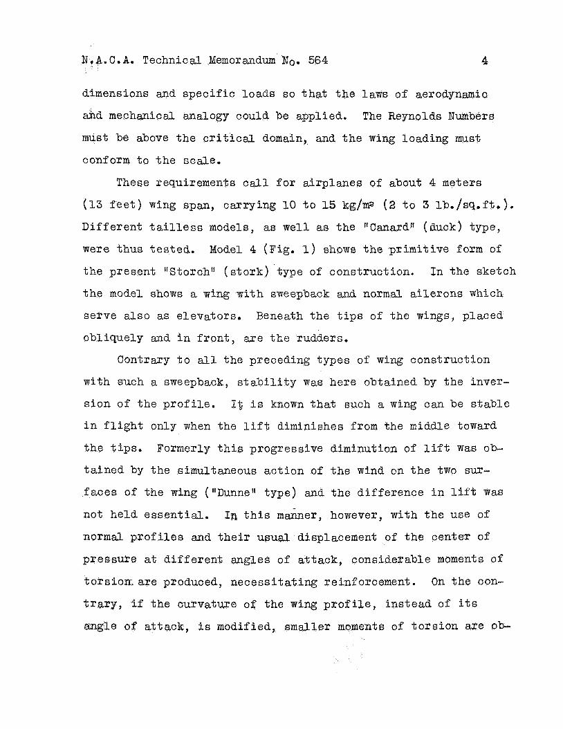
Thec;e requirements c a l l f o r a i rplanes of about 4 meters
(13 f e e t ) wing span, carrying 10 t o 15 kg/m2 ( 2 t o 3 lb./sq.ft,).
Different t a i l l ess models, as well as the I1Canardtt (duck) type,
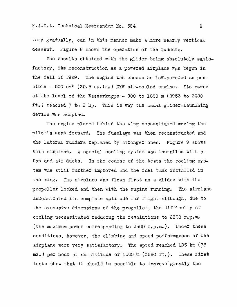
were thus tested. Model 4 (Fig. 1) shows t h e pr imit ive form of
the present ItStorchtt ( s to rk ) type of construction. In the sketch
t h e model shows a wing w i t h saeepback and normal a i le rons which
serve also as elevators. Beneath the t i p s of the wings, placed
obliquely and i n f ron t , a r e t h e rudders.
Contrary t o a11 the preceding types of wing construction
w i t h such a sweepback, s t a b i l i t y was here obtained by the inver-
s ion of t he p ro f i l e . 1% i s known that such a wing can be s t ab le
i n f l i gh t only when the l i f t diminishes from the middle toward
the t ips .
t a ined by the simultaneous ac t ion of t h e wind on t h e two sur-
faces of t h e wing (tlDunnelf type) and the difference i n lift was
not held essent ia l .
normal p r o f i l e s and t h e i r usual. displacement of t he cent
pressure at d i f f e ren t angles o f a t tack , considerable moments of
tors ion- a re produced, necess i ta t ing reinforcement. On the con-
, i f the curvature of the wing p r o f i l e , instead of i t s
Formerly t h i s progressive diminution of l i f t was ob-
In t h i s manner, however, w i t h t h e use of
attack, i s modifi en t s of t o r s ion are ob-
N , A . C , A , Technical Memorandum .Uo. 564 5
t a ined with the excessive sweepback of the wing than
m a l airplane wing, In the flStorchtt with an ordin
camber and thickness diminish i n such a manner t ha t the
o f the wing t i p i s f la t and inverted.
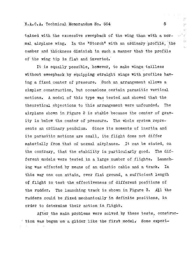
It i s equally possible, however, t o make wings t a i l l e s s
without sweepback by equipping rjtraight wings w i t h p r o f i l e s hav-
ing a f ixed center of pressure. Such an arrangement a l lows a
simpler construction, but occasions c e r t a i n p a r a s i t i c v e r t i c a l
motions.
t h e o r e t i e d objections t o t h i s arrangement were unfounded, The
airplane shown i n Figure 2 i s s tab le because the center of grav-
i t y i s below the center o f pressure, The whole system repre-
sen ts an ordinary pendulum. Since i t s moments of i n e r t i a and
i t s p a r a s i t i c motions are small, i t s f l i g h t does not d i f f e r
mater ia l ly from t h a t of normal airplanes. It can be s ta ted, on
the contrary, t h a t the s t a b i l i t y i s pa r t i cu la r ly good. The dif-
fe ren t models were t e s t ed i n a la rge number o f f l i g h t s . Launch-
ing w a s effected by means of an e l a s t i c cable and a track. In
t h i s way one can a t t a in , over f lat ground, a su f f i c i en t length
of f l i g h t t o t e s t the effect iveness of d i f f e ren t posi t ions of
the rudder. The launching t rack i s shown i n Figure 3, A31 the
A model of t h i s type was t e s t e d and showed t h a t the
i c a l l y i n de f in i t e pos i t ions , i n
t o determine t h e i r act ion i n f l i g h t ,
were solved by these t e s t s , construc-
first model, me experi-
N I A 9 C . A . Technical Iaemorandum No. 564 6
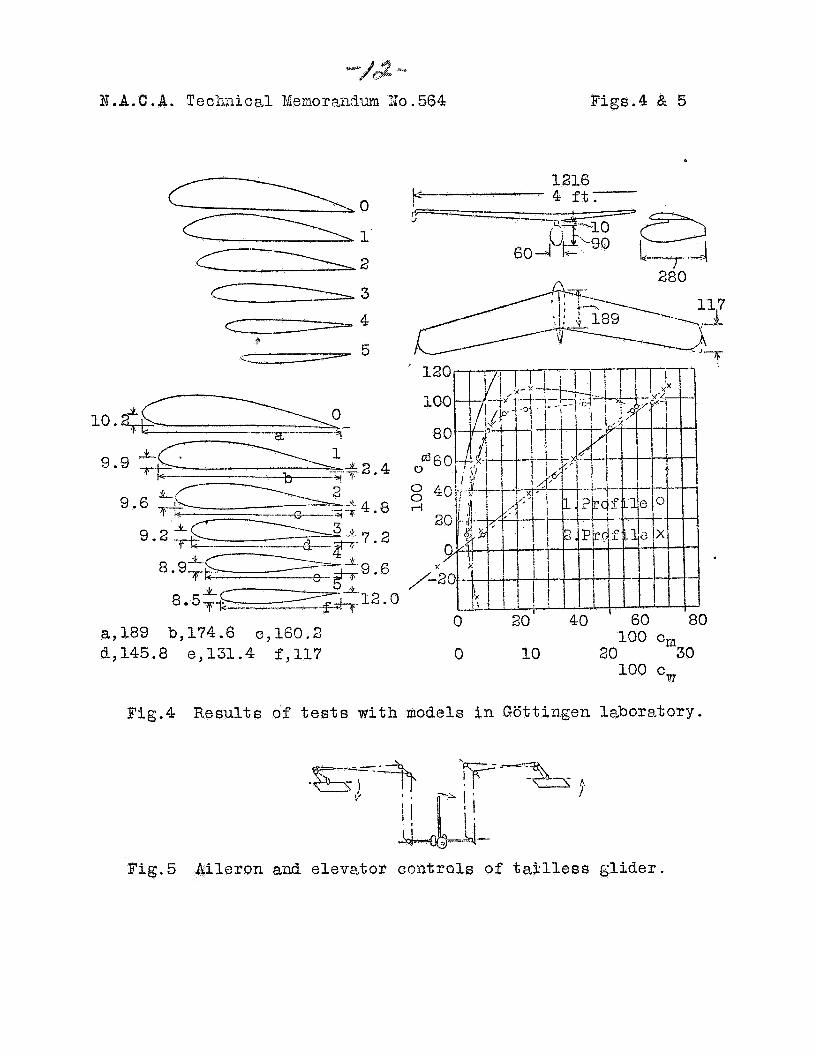
s i n the wind tunnel were then made. It f o t
p r o f i l e s , as designed, were unfavorable f o r the maximum
They were accordingly modified t o approach the Joukowsky t
The models were t e s t e d w i t h the fuselage and it Was ascertained,
on the basis of t he polass, t h z t , w i t h an aspect r a t i o of 8,
excellent f ineness ratios L/D were obtained. The p r o f i l e s
t e s t ed , as well as the p o l a r s , are shown i n Figure 4. Since the
estimates allowed f o r the presence of the fuselage, no addition-
a l calculat ions had t o be made f o r the s t r u c t u r a l drag of f u l l -
s ca l e a i r p l ane s,
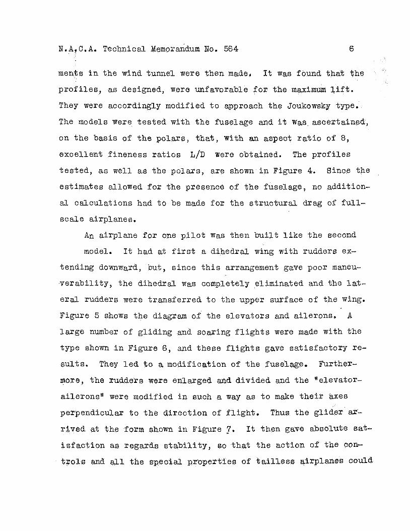
An airplane f o r one p i l o t was then built l i k e the second
model. It had at first a dihedral wing with rudders ex-
tending downward, but, s ince t h i s arrangement gave poor maneu-
ve rab i l i t y , the d i h e d r d was completely eliminated and the la%-
era3 rudders were t ransfer red t o the upper surface of the wing.
Figure 5 shows the diagram of the e leva tors and ai lerons,
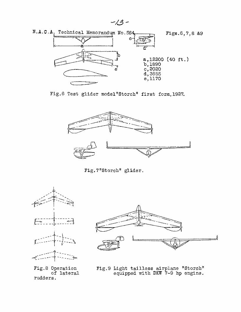
l a rge number o f g l id ing and soaring f l i g h t s were made w i t h the
type shown i n Figure 6 , and these f l i g h t s gave sa t i s f ac to ry re-
s u l t s . They l e d t o a modification of the fuselage. Further-
more, the rudders were enlarged and divided and the Helevator-
a i le rons" were modified i n such a way as t o make t
A
pendiculax t o t he d i rec t ion of f l i g h t , Thus the g l ide r a-
r ived at the form shown i n Figure ,7.
i s f a c t i o n as r e i l i t y , so that t he act ion of the con-
It then gave absolute sat-
and all the spe P of could
7 J,A. 6. A. Technical Xemorandum No. 564 ..-
be studied i n numerous g l id ing and soaring f l i g h t s ,
These f l i g h t s , which took place during the summer of 1929,
gave the following resu l t s . I n horizontal f l i g h t , the elevator
mas more sens i t ive than that of a normal airplaae. The move-
lizents were shorter and by je rks , but t h i s sensit iveness w a s not
disagreeable because it f a c i l i t a t e d the trmsitioa from one at-
t i t u d e of f l i g h t t o another. It vdas likewise possible t o render
the g l ider more s tab le i n t h i s respect by s l i gh t modifications
of the prof i le . If the controls were hanfiled as f o r a ve r t i ca l
landing, a s t ab le attitude of f l i g h t w a s obtained without any
tendency t o s ide s l i p o r assume another a t t i t u d e of f l i g h t . The
ac t ion of the rudders w a s conserved i n s p i t e of a very reduced
speed, s o that a change of course could be aade under these con-
di t ions.
The se t t i ng of the elevator by degrees and locking i t did
not cause loss o f s t a b i l i t y . The g l ide r ascended and descended
v e r t i c a l l y , u n t i l norizjl f l i g h t w a s a t t a ined while continuing t o
f l y at a la rge angle of a t tack . Here a l s o the extraordinary ef-
fect iveness of t he controls was especial ly evideit.
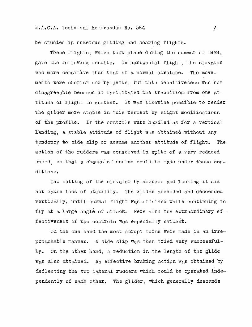
On the one hand the m-ost abrupt tu rns were made i n rn i r r e -
proachable mm-ner. A s ide s l i p was then t r i e d very successful-
l y ,
w a s also at ta ined, An e f fec t ive braking action W a s obtained by
def lec t ing the two l a t e r d rudders which could be operated inde-
pendently of each other, The g l ide r , which generally descends
On the other hand, a reduction i n the lezlgth o f the g l ide
N . A . C . A . Technical. Ideaorandurn 80. 564 a
very gradually, can i n t h i s manner make a more n e a l y v e r t i c a l
descent. Figure 8 shows the operation of the rudders.
The r e s u l t s obtained with the g l ide r being absolutely satis-
fac tory , i t s reconstruction as a powered airplane was begun i n
the f a l l of 1929. The engine w a s chosen as low-powered as pos-
s i b l e - 500 cm3 (30.5 cu.in. ) DKW air-cooled engine. Its power
at the l eve l of the Wasserkuppe*- 900 t o 1000 m (2953 t o 3280
f t . ) reached 7 t o 9 hp.
device w a s adopted.
This i s wny t h e usual glider-launching
The engine placed behind the wing necessi ta ted moving the
p i l o t ' s seat forward. Tne fuselage w a s then reconstructed and
the 1ateraJ. rudders replaced by stronger ones. Figure 9 shows
t h i s airplane. A special cooling system w a s i n s t a l l e d with a,
f an and air ducts. In the course of t he t e s t s t he cooling sys-
tern w a s s t i l l fur ther iaproved md the f u e l tank i n s t a l l e d i n
the wing. The airplane was flown first as a g l ide r with the
propel le r locked aad then wi th the engine running. The airplane
demonstrated i t s complete apti tude f o r f l i g h t although, due t o
the excessive dimensions of t h e propel le r , the d i f f i c u l t y of
cooling necessi ta ted reducing the revolutions t o 2800 r.p.m.
( t h e maximum power corresponding t o 3300 r.p.ni.).
conditions, however, the climbing and speed performances of t he
airplane were very sa t i s fac tory .
m i . ) per h o w at an a l t i t u d e of 1000 m (3280 f t , ) .
t e s t s show tha t it should be possible t o improve-greatly the
Under these
The speed reached 125 km (78
These first
N.A.C.A. Technical Xernorandim No, 564 9
performances of t a i l l e s s airplanes. The airplane w a s exhibited
i n f l i g h t t o a l a rge number of G e r r n a n and foreign spec ia l i s t s .
It w a s per fec t ly and successfully p i lo t ed during all these dem-
ons t ra t ions by Groenhoff.
The t a i l l e s s a i rplane i s of special i n t e re s t i n every case
where it i s desired t o iaprove %he eco
t h a t i s t o say , i n pa r t i cu la r , f o r comaercijl a i rplanes used on
long f l i gh t s . This impovement of performance should l eve l the
b a r r i e r s which s t i l l prevent the airplaxne from f inding i t s use
i n domains where i t shouLld render valusble service i n economic
and social l i f e .
Character is t ics of the ftStorchll Airplaxe
S p a
Length
Height
Chord at center of wing
Chord at end of w i n g
Wing area
Area of elevator-ailerons, each
Area of rudders w i t h f i n s , each
Engine, DKW, air-cooled
Propel le r , RRG
Weight, eapty
Load carr ied
12.37 ... m 40.58 f t .
3,8 It 12.47 "
2,o 'I 6.56
1.89 6.20 I'
1.17 - I' 3,84
18.5 rn2 199.13 sq.ft.
0.93 I1 10.01 "
0.80 8.61 I'
7-9 hp
1.24/0.6 rn H 4.07/1.9_7 ft.p.
1_70 kg 374.8 -- lb.
80 176.4 I'
N e A e C o A o Technical Memorandum No. 564 10
Weight i n f l i g h t 250.0 kg ,551.2 lb,
Wing loading 13.5 kg/m2 2D77 -- lbo / S q o f t e
Power loading 30.0 kg/hp 65.2 lbe/hp
Power per uni t area 0.45 hp/m2 D 0 42 hP/ Sq f f D
Translation by National Advisory Cornnittee f o r Aeronautics.
-//-
N.B.O.A. Technical Menorandm Bo. 564 Figs. 1,2 E: 3
“3.140
Fig. 1 godel ru’o.4 Wing area 2 rn2 Weight 14 kg. 21e53 Sqsftv 30.86 rib.
Fig. 2 EJlodel 30.6 Wing i?reE: 1.6 rz2 Veight 12 kg. 17.22 Sqeft, 26.46 lb.
Fig. 3 Starti i lg t r ack f o r t e s t mo3eEs
Figs.4 & 5
------ 10.-
9.9
9.
.4
.8
.2
a,189 b,174.6 0,160.2 d,145.8
Fig.4
Fig.5
1216 k- ! .p ft.
A 2SO
190 c,, e,131.4 f,117 0 10 20 '"30
100 Cm
Results of tests w i t h models in Gattingen l abora tory .
Ai le ron and e leva to r con tmls of t ag l l e s s glider.
N . P . G . A : Technical Memorandy No.56 C
Figs.6,7,8 &9
n I Ul a
.=-, ,->--=
ic 1 2 a,12200 (40 ft.)
b, 1890
d, 3655 - e, 1170
c , 2020 9 cz===-
Fig.6 Test g l ide r modelnStorch" f i r s t form, 1927.
Fig. 7rrStorch'1 g l ider .
Fig.8 Operation
rudders. of l a t e r a l
Fig.9 Light % n i l l e s s airplzne "Storchf1 equipped w i t h DKW 7-9 hp engine.


