65
EE 595 Part IV Basic Elements in VHDL EE 595 EDA / ASIC Design Lab

EE 595
Part IVBasic Elements in VHDL
EE 595 EDA / ASIC Design Lab

IdentifiersAn identifier can be any length, in other words, as many characters as desiredAn identifier is case insensitive, meaning that there is no differencebetween uppercase and lowercase letters. (For example XOR2_OP2 and XOr2_Op denote the same identifier.)The allowed characters are a-z (lowercase letters), A-Z (uppercase letters), 0-9 (numerals), and _ (underscore).The first character is a letter and the last character must not be underscore.No adjacent underscore are allowed.
EE 595 EDA / ASIC Design Lab

Identifiers (cont’d)The identifiers discussed in the previous slide are called basicidentifiers and their construction rules can, at times, be overlyrestrictive. For example digital system data books often designate apart name with leading numerals, such as 74HC00. Digital systemdata books also often designate active-0 signal state with a leadingslash, such as /ALARM, or a trailing dash, such as ALARM-. Thesesample names are not legal VHDL names. The inability to express these names in VHDL impedes describingExisting designs in VHDL and often leads to cumbersome andawkward. Hence VHDL-93 provides an enhanced set of rulesconstructing identifiers that include both the basic identifiers andmore general identifiers, called extended identifiers.
EE 595 EDA / ASIC Design Lab
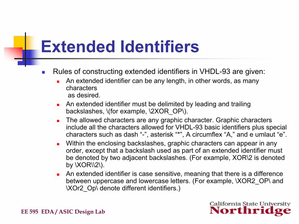
Extended IdentifiersRules of constructing extended identifiers in VHDL-93 are given:
An extended identifier can be any length, in other words, as many characters as desired.An extended identifier must be delimited by leading and trailingbackslashes, \(for example, \2XOR_OP\).The allowed characters are any graphic character. Graphic characters include all the characters allowed for VHDL-93 basic identifiers plus special characters such as dash “-”, asterisk “*”, A circumflex “A,” and e umlaut “e”. Within the enclosing backslashes, graphic characters can appear in any order, except that a backslash used as part of an extended identifier must be denoted by two adjacent backslashes. (For example, XOR\2 is denoted by \XOR\\2\).An extended identifier is case sensitive, meaning that there is a difference between uppercase and lowercase letters. (For example, \XOR2_OP\ and \XOr2_Op\ denote different identifiers.)
EE 595 EDA / ASIC Design Lab

Extended Identifier (cont’d)An extended identifier is different from any keyword or basic identifier. (Thus, \entity\ is a legal extended identifier because it is different entity.Also, the extended identifier \XOR2_OP\ and the basic identifier XOR2_Opdo not denote same name.
EE 595 EDA / ASIC Design Lab
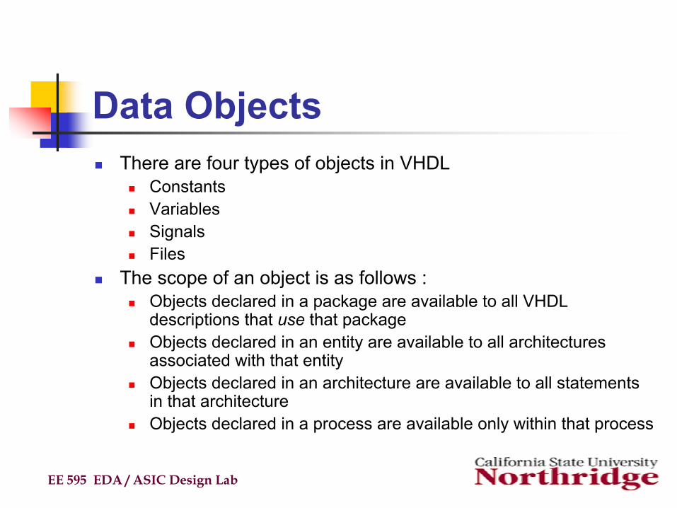
Data ObjectsThere are four types of objects in VHDL
ConstantsVariablesSignalsFiles
The scope of an object is as follows :Objects declared in a package are available to all VHDL descriptions that use that packageObjects declared in an entity are available to all architecturesassociated with that entityObjects declared in an architecture are available to all statements in that architectureObjects declared in a process are available only within that process
EE 595 EDA / ASIC Design Lab

Data Objects (cont’d)Signal - Values scheduled in the future, only means to communicate between processes. It is “Global”, it uses up simulator time.
Constants - Value fixed during initialization and can only be manipulated by a debugger. It names a specific value.
Variables - Value assigned immediately when the line is executed and is valid within processes and subprograms. (Local storage or wires)
Note: Names are not case sensitive, but must not be reserved words.
EE 595 EDA / ASIC Design Lab

Data ObjectsConstants
Name assigned to a specific value of a typeAllow for easy update and readabilityDeclaration of constant may omit value so that the value assignment may be deferred
Facilitates reconfigurationDeclaration syntax :
Declaration examples :
EE 595 EDA / ASIC Design Lab
constant CONSTANT_NAME : TYPE_NAME [:= VALUE];constant CONSTANT_NAME : TYPE_NAME [:= VALUE];
constant PI : real := 3.14;constant SPEED : integer;constant VEC3 : Bit_Vector (0 TO 3) := “1101”;
constant PI : real := 3.14;constant SPEED : integer;constant VEC3 : Bit_Vector (0 TO 3) := “1101”;

Data ObjectsVariables
Provide convenient mechanism for local storageE.g. loop counters, intermediate values, etc.
Scope is process in which they are declaredVHDL ‘93 provides for global variables, to be discussed in the Advanced Concepts in VHDL module
All variable assignments take place immediatelyNo delta or user specified delay is incurred
Declaration syntax:
Declaration examples :
EE 595 EDA / ASIC Design Lab
variable VARIABLE_NAME : TYPE_NAME [:= VALUE];variable VARIABLE_NAME : TYPE_NAME [:= VALUE];
variable OPCODE : Bit_Vector(3 DOWNTO 0) := "0000";variable FREQ : integer;
variable OPCODE : Bit_Vector(3 DOWNTO 0) := "0000";variable FREQ : integer;

Data Objects Variables (cont’d)
Can be scalar or array and can be constrained and initialized
Local Data inside a process or (subprogram)Assigned immediatelyVariable assignments do not use any simulated timeRight hand side must match the type of the left hand Side typeRight hand side can be an expression using operators ...
EE 595 EDA / ASIC Design Lab
variable ABC : Bit;variable DEF : integer range 0 to 9 := 3;
variable ABC : Bit;variable DEF : integer range 0 to 9 := 3;
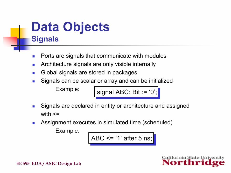
Data ObjectsSignals
Ports are signals that communicate with modulesArchitecture signals are only visible internallyGlobal signals are stored in packagesSignals can be scalar or array and can be initialized
Example:
Signals are declared in entity or architecture and assigned with <=Assignment executes in simulated time (scheduled)
Example:
EE 595 EDA / ASIC Design Lab
signal ABC: Bit := ‘0’;signal ABC: Bit := ‘0’;
ABC <= ‘1’ after 5 ns;ABC <= ‘1’ after 5 ns;

Data Objects Signals (cont’d)
Used for communication between VHDL componentsReal, physical signals in system often mapped to VHDL signalsALL VHDL signal assignments require either delta cycle or user-specified delay before new value is assumedDeclaration syntax :
Declaration and assignment examples :
EE 595 EDA / ASIC Design Lab
signal SIGNAL_NAME : TYPE_NAME [:= VALUE];signal SIGNAL_NAME : TYPE_NAME [:= VALUE];
signal BRDY : Bit;BRDY <= ‘0’ after 5ns, ‘1’ after 10ns;
signal BRDY : Bit;BRDY <= ‘0’ after 5ns, ‘1’ after 10ns;
Data Objects Signals (cont’d)
EE 595 EDA / ASIC Design Lab
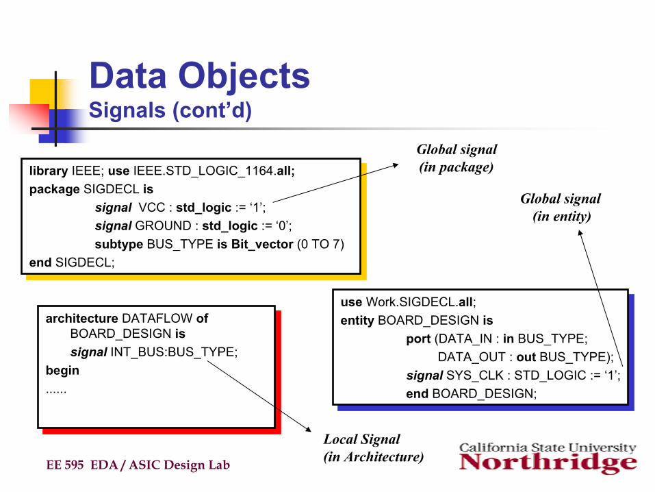
library IEEE; use IEEE.STD_LOGIC_1164.all;package SIGDECL is
signal VCC : std_logic := ‘1’;signal GROUND : std_logic := ‘0’;subtype BUS_TYPE is Bit_vector (0 TO 7)
end SIGDECL;
library IEEE; use IEEE.STD_LOGIC_1164.all;package SIGDECL is
signal VCC : std_logic := ‘1’;signal GROUND : std_logic := ‘0’;subtype BUS_TYPE is Bit_vector (0 TO 7)
end SIGDECL;
use Work.SIGDECL.all;entity BOARD_DESIGN is
port (DATA_IN : in BUS_TYPE;DATA_OUT : out BUS_TYPE);
signal SYS_CLK : STD_LOGIC := ‘1’;end BOARD_DESIGN;
use Work.SIGDECL.all;entity BOARD_DESIGN is
port (DATA_IN : in BUS_TYPE;DATA_OUT : out BUS_TYPE);
signal SYS_CLK : STD_LOGIC := ‘1’;end BOARD_DESIGN;
architecture DATAFLOW of BOARD_DESIGN issignal INT_BUS:BUS_TYPE;
begin......
architecture DATAFLOW of BOARD_DESIGN issignal INT_BUS:BUS_TYPE;
begin......
Global signal(in package)
Global signal (in entity)
Local Signal (in Architecture)

Data ObjectsSignals Versus Variables
EE 595 EDA / ASIC Design Lab
architecture TEST1 of MUX issignal X : Bit := '1';signal Y : Bit := '0';
beginprocess (IN_SIG)
beginX <= IN_SIG XOR Y;y <= IN_SIG XOR X;
end process;end TEST1;
architecture TEST1 of MUX issignal X : Bit := '1';signal Y : Bit := '0';
beginprocess (IN_SIG)
beginX <= IN_SIG XOR Y;y <= IN_SIG XOR X;
end process;end TEST1;
architecture TEST2 of MUX is signal Y : Bit := '0';
beginprocess (IN_SIG)
variable X : Bit := '1';begin
X := IN_SIG XOR Y;Y <= IN_SIG XOR X;
end process;end TEST2;
architecture TEST2 of MUX is signal Y : Bit := '0';
beginprocess (IN_SIG)
variable X : Bit := '1';begin
X := IN_SIG XOR Y;Y <= IN_SIG XOR X;
end process;end TEST2;
This example highlights the difference between signals and variables
Assuming 1 -> 0 transition on in_sig, what are the resulting values for y in both cases?
Data ObjectsSignals Versus Variables (cont’d)
EE 595 EDA / ASIC Design Lab
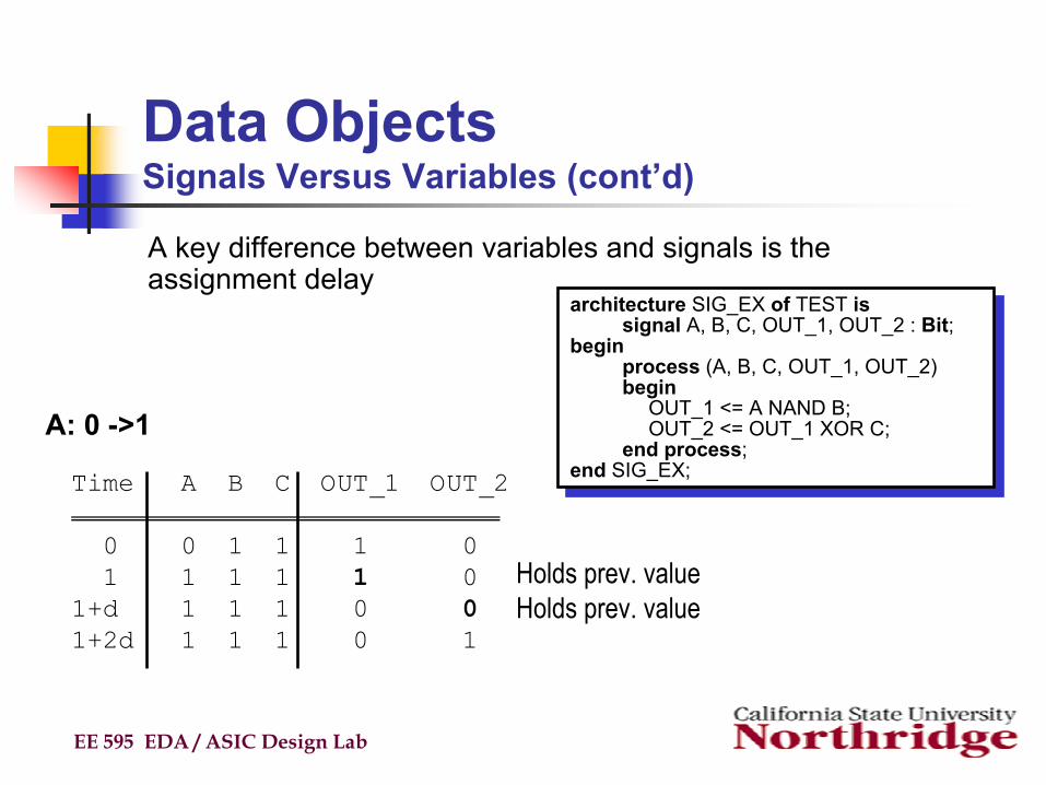
architecture SIG_EX of TEST issignal A, B, C, OUT_1, OUT_2 : Bit;
beginprocess (A, B, C, OUT_1, OUT_2)begin
OUT_1 <= A NAND B;OUT_2 <= OUT_1 XOR C;
end process;end SIG_EX;
architecture SIG_EX of TEST issignal A, B, C, OUT_1, OUT_2 : Bit;
beginprocess (A, B, C, OUT_1, OUT_2)begin
OUT_1 <= A NAND B;OUT_2 <= OUT_1 XOR C;
end process;end SIG_EX;
A key difference between variables and signals is the assignment delay
Time A B C OUT_1 OUT_2
0 0 1 1 1 01 1 1 1 1 0
1+d 1 1 1 0 01+2d 1 1 1 0 1
A: 0 ->1
Holds prev. valueHolds prev. value
Data ObjectsSignals Versus Variables (cont’d)
EE 595 EDA / ASIC Design Lab
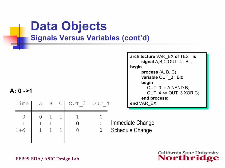
architecture VAR_EX of TEST issignal A,B,C,OUT_4 : Bit;
beginprocess (A, B, C)variable OUT_3 : Bit;begin
OUT_3 := A NAND B;OUT_4 <= OUT_3 XOR C;
end process;end VAR_EX;
architecture VAR_EX of TEST issignal A,B,C,OUT_4 : Bit;
beginprocess (A, B, C)variable OUT_3 : Bit;begin
OUT_3 := A NAND B;OUT_4 <= OUT_3 XOR C;
end process;end VAR_EX;Time A B C OUT_3 OUT_4
0 0 1 1 1 01 1 1 1 0 0
1+d 1 1 1 0 1
A: 0 ->1
Schedule ChangeImmediate Change

Data ObjectsSignals Versus Variables (cont’d)
EE 595 EDA / ASIC Design Lab
Signal Assignment
Signal Values are Scheduled
Can have delay
Signal updated only when allprocesses are suspended (waiting).
Variable Assignment
Variable Values are not Scheduled
Values updated without delay
Variables updated immediately within the process (while the process is executing)

Data ObjectsFiles
Files provide a way for a VHDL design to communicate with the host environmentFile declarations make a file available for use to a designFiles can be opened for reading and writing
In VHDL87, files are opened and closed when their associated objects come into and out of scopeIn VHDL93 explicit FILE_OPEN() and FILE_CLOSE() procedures were added
The package STANDARD defines basic file IO routines for VHDL typesThe package TEXTIO defines more powerful routines handling IO of text files
EE 595 EDA / ASIC Design Lab
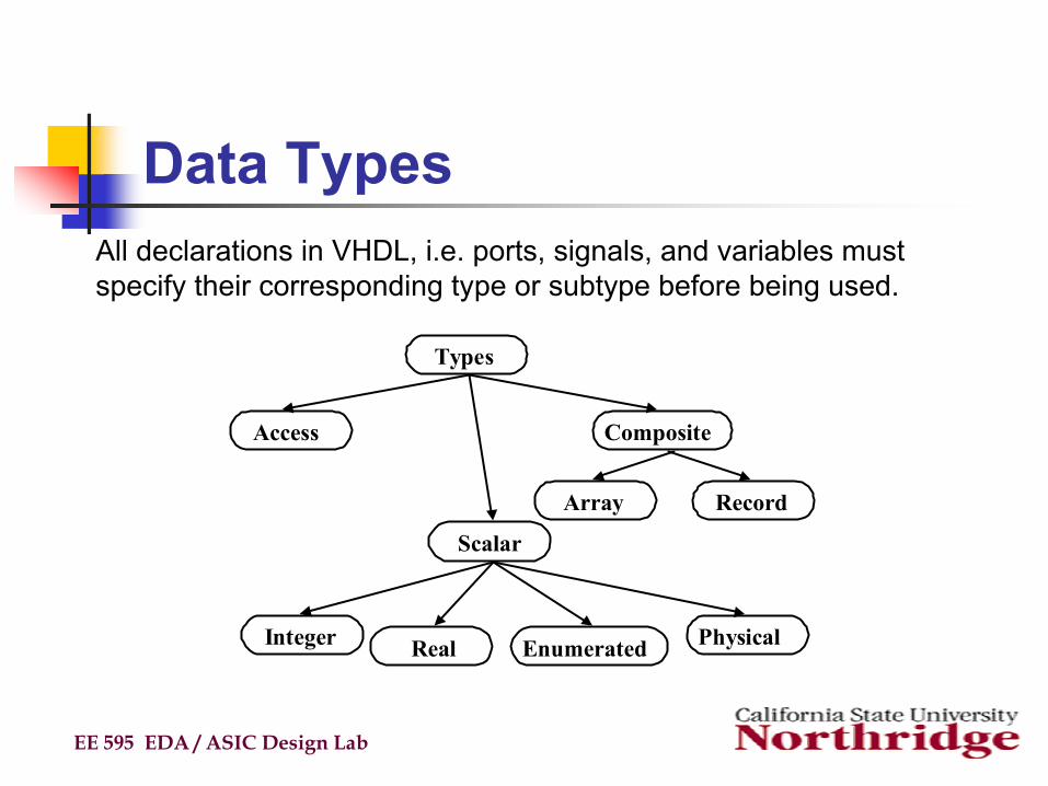
Data Types
EE 595 EDA / ASIC Design Lab
All declarations in VHDL, i.e. ports, signals, and variables must specify their corresponding type or subtype before being used.
Types
Access
Scalar
Composite
Array Record
Integer Real Enumerated Physical

Data Types (cont’d)VHDL is a rich language with many different data types.The most common data types are
bit: a 1-bit value representing a wire. (Note: IEEE standard 1164 defines a 9-valued replacement for bit called std_logic).
bit_vector: an array of bits. (Replaced by std_logic_vector in IEEE 1164)boolean: a True/False value.integer: a signed integer value, typically implemented as a 32-bit data type.real: a floating point value.enumerated: used to create custom data types.record: used to append multiple data types as a collection.array: can be used to create single or multiple dimension arrays.access: similar to pointers in C or Pascalfile: used to read and write disk files. Useful for simulationphysical: used to represent values such as time, voltage, etc.. using symbolic units ofmeasure (such as ‘ns’ or ‘ma’)
EE 595 EDA / ASIC Design Lab
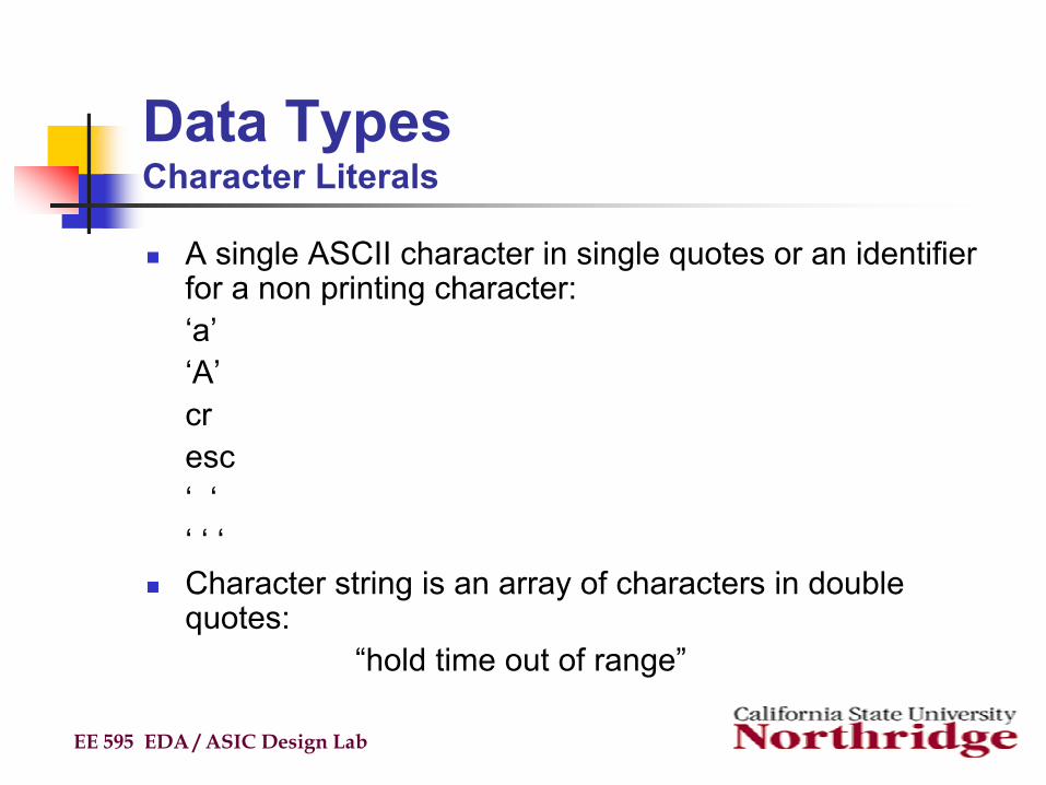
Data TypesCharacter Literals
A single ASCII character in single quotes or an identifier for a non printing character:‘a’‘A’cresc‘ ‘‘ ‘ ‘Character string is an array of characters in double quotes:
“hold time out of range”
EE 595 EDA / ASIC Design Lab

Data TypesBit Literals
Bit can only be ‘0’ ‘1’Vendors often extend VHDL defined types with other
valuesBit_Vector is an array of Bits defined in double quotes
Example: “001100”Base precedes sequence
Binary B, default if no base specifiedOctal OHexadecimal X
Example: X”7E”
EE 595 EDA / ASIC Design Lab
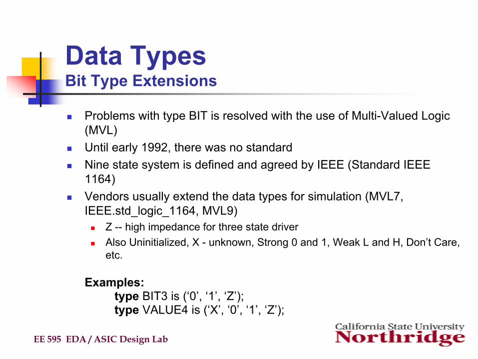
Data TypesBit Type Extensions
Problems with type BIT is resolved with the use of Multi-Valued Logic (MVL)Until early 1992, there was no standardNine state system is defined and agreed by IEEE (Standard IEEE 1164)Vendors usually extend the data types for simulation (MVL7, IEEE.std_logic_1164, MVL9)
Z -- high impedance for three state driverAlso Uninitialized, X - unknown, Strong 0 and 1, Weak L and H, Don’t Care, etc.
Examples:type BIT3 is (‘0’, ‘1’, ‘Z’);type VALUE4 is (‘X’, ‘0’, ‘1’, ‘Z’);
EE 595 EDA / ASIC Design Lab

Data TypesStandard Logic
EE 595 EDA / ASIC Design Lab
type STD_ULOGIC is ( ‘U’ uninitialized‘X’ forcing to unknown‘0’ forcing to 0‘1’ forcing to 1‘Z’ high impedance (Three State)‘W’ weak unknown‘L’ weak 0‘H’ weak 1‘-’ don’t care );
type STD_ULOGIC is ( ‘U’ uninitialized‘X’ forcing to unknown‘0’ forcing to 0‘1’ forcing to 1‘Z’ high impedance (Three State)‘W’ weak unknown‘L’ weak 0‘H’ weak 1‘-’ don’t care );
std_ulogicstd_ulogic_vector
std_ulogicstd_ulogic_vector
std_logicstd_logic_vector
std_logicstd_logic_vector
Defined in Package “Std_Logic_1164”“Std_Logic” has same values as “Std_ulogic” ?
A
B
Z

Data TypesRules to use std_Logic and std_ulogic
EE 595 EDA / ASIC Design Lab
signal A,B, Z : std_ulogic;signal RES_Z : std_logic;
signal A,B, Z : std_ulogic;signal RES_Z : std_logic;
?A
B
Z ?A
B
RES_Z
A Z A RES_Z
Z <= A;Z <= A;
Z <= A;Z <= B;
Z <= A;Z <= B;
RES_Z <= A;RES_Z <= A;
RES_Z <= A;RES_Z <= B;
RES_Z <= A;RES_Z <= B;
Cannot assign std_logic_vector to std_ulogic_vector

Data Typestd_Logic Properties
EE 595 EDA / ASIC Design Lab
std_ulogicstd_ulogic_vector
std_ulogicstd_ulogic_vector
std_logicstd_logic_vector
std_logicstd_logic_vector
• Std_ulogic benefits•Gives errors when accidentallyhave two drivers
• Std_logic benefits• Other standards based on it
• Gate Level Simulation• Mathematical Functions
• Synthesis tools only output netlistsin one data type
• Required so tri-state busses work• Generally no simulation speed overhead
• Std_ulogic benefits•Gives errors when accidentallyhave two drivers
• Std_logic benefits• Other standards based on it
• Gate Level Simulation• Mathematical Functions
• Synthesis tools only output netlistsin one data type
• Required so tri-state busses work• Generally no simulation speed overhead
std_logic is best when used for RTL
Data Typebit_vector
EE 595 EDA / ASIC Design Lab
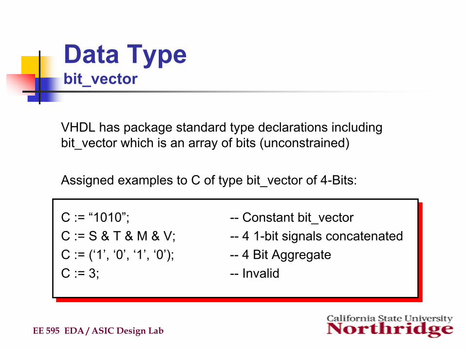
VHDL has package standard type declarations including bit_vector which is an array of bits (unconstrained)
Assigned examples to C of type bit_vector of 4-Bits:
C := “1010”; -- Constant bit_vectorC := S & T & M & V; -- 4 1-bit signals concatenatedC := (‘1’, ‘0’, ‘1’, ‘0’); -- 4 Bit AggregateC := 3; -- Invalid

Data TypeBoolean Literals
Boolean is pre-defined to be False, True
Relational Operators (=, <=, >=, /=) produce a Boolean result
Boolean values can be tested in if statements and assigned
A Boolean is not a Bit and has no pre-defined relationship to a Bit
A user conversion routine could define a Bit/Boolean relationship.
EE 595 EDA / ASIC Design Lab

Data TypeBuilt-in and Pre-defined Types
A few types are built-in the language/compiler
Most types pre-declared in the package standard:Bit, Boolean, Character, Bit_Vector, string, Line, Text
Example of type declaration from package:type Boolean is (False, True);
User needs to declare types: default initial valueReal arrayInteger arraySpecial types
Constants, signals and variables must be of a previously declared type
EE 595 EDA / ASIC Design Lab

Data TypeScalar Types
EE 595 EDA / ASIC Design Lab
Integer Minimum range for any implementation as defined by standard: - 2,147,483,647 to 2,147,483,647Example assignments to a variable of type integer :
architecture TEST_INT of test isbegin
process (X)variable A: integer;
beginA := 1; -- OKA := -1; -- OKA := 1.0; -- illegal
end process;end TEST_INT;
architecture TEST_INT of test isbegin
process (X)variable A: integer;
beginA := 1; -- OKA := -1; -- OKA := 1.0; -- illegal
end process;end TEST_INT;
Data TypeScalar Types (cont’d)
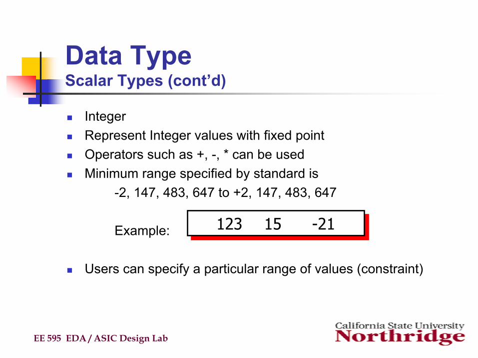
IntegerRepresent Integer values with fixed pointOperators such as +, -, * can be usedMinimum range specified by standard is
-2, 147, 483, 647 to +2, 147, 483, 647
Example:
Users can specify a particular range of values (constraint)
EE 595 EDA / ASIC Design Lab
123 15 -21123 15 -21

Data TypeScalar Types (cont’d)
Real Minimum range for any implementation as defined by standard: -1.0E38Example assignments to a variable of type real :
EE 595 EDA / ASIC Design Lab
architecture TEST_REAL of TEST isbegin
process (X)variable A: real;
beginA := 1.3; -- OKA := -7.5; -- OKA := 1; -- illegalA := 1.7E13; -- OKA := 5.3 ns; -- illegal
end process;end TEST_REAL;
architecture TEST_REAL of TEST isbegin
process (X)variable A: real;
beginA := 1.3; -- OKA := -7.5; -- OKA := 1; -- illegalA := 1.7E13; -- OKA := 5.3 ns; -- illegal
end process;end TEST_REAL;

Data TypeScalar Types (cont’d)
EE 595 EDA / ASIC Design Lab
1.0 1 illegal integer value-1.0 E 101.5 E -205.3
1.0 1 illegal integer value-1.0 E 101.5 E -205.3
Real LiteralsRepresent Floating Point valuesFormat is: + or - number.number [E + or - number]Example:
decimal point is required

Data TypeRange Constraints
Simulator checks for valid type and range on assignment
Range constraint specifies a restricted range
Examples:
Used to qualify the intended usage of data
EE 595 EDA / ASIC Design Lab
integer range 0 to 90 to 9 (Integer type is implicit because of literals)
real range 1.0 to 1.1integer range (no constraint)
integer range 0 to 90 to 9 (Integer type is implicit because of literals)
real range 1.0 to 1.1integer range (no constraint)

Data TypeSlice of an Array
A subscript array reference can be used on either side of a signal or variables assignment statementExample:
EE 595 EDA / ASIC Design Lab
port(A: in Bit_Vector(0 TO 4); -- Direction of DeclarationC: out Bit_Vector(8 DOWNTO 1)); -- and Slice must be same
....
C(6 DOWNTO 3) <= A(0 TO 3); -- OKC(5 DOWNTO 0) <= A(3 DOWNTO 0) -- ILLEGAL
port(A: in Bit_Vector(0 TO 4); -- Direction of DeclarationC: out Bit_Vector(8 DOWNTO 1)); -- and Slice must be same
....
C(6 DOWNTO 3) <= A(0 TO 3); -- OKC(5 DOWNTO 0) <= A(3 DOWNTO 0) -- ILLEGAL
Note: Size of array on left and right must be equal
Data TypeArray Assignment
EE 595 EDA / ASIC Design Lab
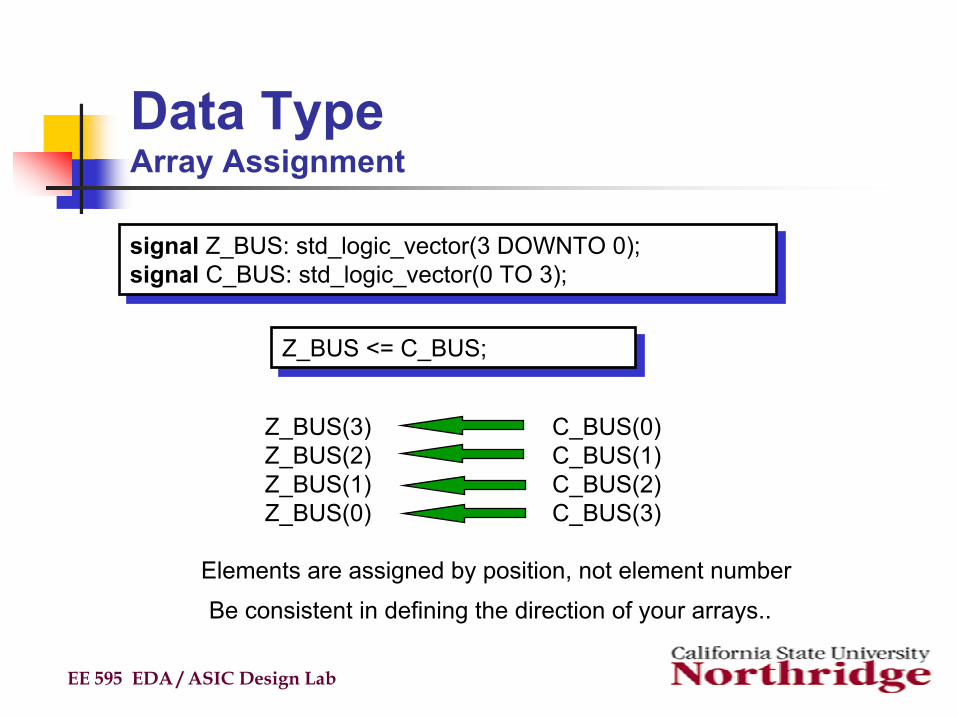
signal Z_BUS: std_logic_vector(3 DOWNTO 0);signal C_BUS: std_logic_vector(0 TO 3);
signal Z_BUS: std_logic_vector(3 DOWNTO 0);signal C_BUS: std_logic_vector(0 TO 3);
Z_BUS <= C_BUS;Z_BUS <= C_BUS;
Z_BUS(3)Z_BUS(2) Z_BUS(1) Z_BUS(0)
C_BUS(0)C_BUS(1) C_BUS(2) C_BUS(3)
Elements are assigned by position, not element number
Be consistent in defining the direction of your arrays..

Data TypeArray Example
EE 595 EDA / ASIC Design Lab
architecture ...begin
processvariable DATA : Bit_Vector(0 TO 31);variable START : integer range 0 TO 24;variable DATA_OUT : Bit_Vector (0 TO 7)...
beginfor i in 0 to 7 loop
DATA_OUT(i) := DATA(i + START);end loop;...
end process; Array ... Access
architecture ...begin
processvariable DATA : Bit_Vector(0 TO 31);variable START : integer range 0 TO 24;variable DATA_OUT : Bit_Vector (0 TO 7)...
beginfor i in 0 to 7 loop
DATA_OUT(i) := DATA(i + START);end loop;...
end process; Array ... Access

Data TypeArray Example
EE 595 EDA / ASIC Design Lab
architecture EXAMPLE of ARRAY isbegin
process(A)type BIT4 is ARRAY(0 TO 3) of Bit;type BIT8 is ARRAY (0 TO 7) of Bit;variable Q8 : Bit8;variable Q4A, Q4B : Bit4;
beginQ4A := (‘1’, ‘1’,’1’,’1’); -- aggregate assignmentQ4B := “1010” ; -- aggregate assignmentQ8 := (‘0’,’1’,others => ‘0’); -- aggregate assignmentQ8 := (others => ‘0’); -- aggregate assignmentQ8(2) := ‘1’; -- assignment to a sliceQ8(5 TO 7) := “111”; -- assignment to a sliceQ8 := “010” & “00110”; -- concatenation
end process;end EXAMPLE;

Data TypeScalar Types
EE 595 EDA / ASIC Design Lab
type BINARY is ( ON, OFF );... some statements ...architecture TEST_ENUM of TEST isbegin
process (X)variable A: BINARY;
beginA := ON; -- OK... more statements ...A := OFF; -- OK... more statements ...
end process;end TEST_ENUM;
type BINARY is ( ON, OFF );... some statements ...architecture TEST_ENUM of TEST isbegin
process (X)variable A: BINARY;
beginA := ON; -- OK... more statements ...A := OFF; -- OK... more statements ...
end process;end TEST_ENUM;

Data TypeScalar Types (cont’d)
PhysicalRequire associated unitsRange must be specifiedExample of physical type declaration :
EE 595 EDA / ASIC Design Lab
type RESISTANCE is range 0 TO 1000000
UNITSOHM; -- ohmKOHM = 1000 OHM; -- i.e. 1 KOHMMOHM = 1000 KOHM; -- i.e. 1 MOHMend UNITS;
type RESISTANCE is range 0 TO 1000000
UNITSOHM; -- ohmKOHM = 1000 OHM; -- i.e. 1 KOHMMOHM = 1000 KOHM; -- i.e. 1 MOHMend UNITS;
Time is the only physical type predefined in VHDL standard
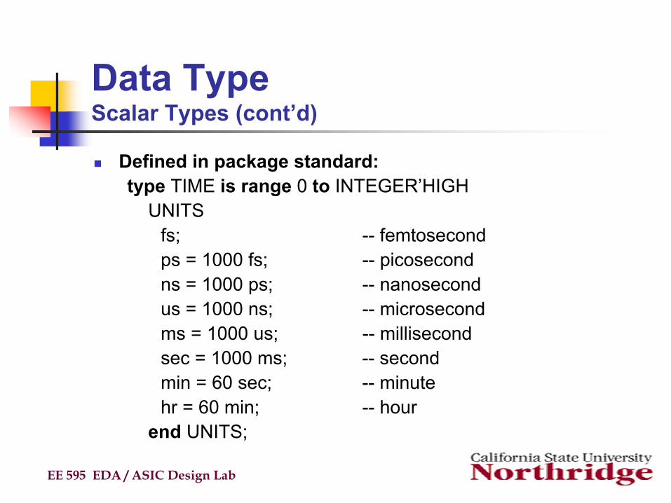
Data TypeScalar Types (cont’d)
Defined in package standard:type TIME is range 0 to INTEGER’HIGH
UNITSfs; -- femtosecondps = 1000 fs; -- picosecondns = 1000 ps; -- nanosecondus = 1000 ns; -- microsecondms = 1000 us; -- millisecondsec = 1000 ms; -- secondmin = 60 sec; -- minutehr = 60 min; -- hour
end UNITS;
EE 595 EDA / ASIC Design Lab

Data TypeEnumerated Types
Defines legal values through an enumerated list of:Character Literals: ‘x’Identifiers: STATE_IDLE
Example:
Uses symbolic codes instead of numeric valuesProvides for more abstract representation in source designSimulator systems require more values than ‘0’, ‘1’user defines list of possible values
EE 595 EDA / ASIC Design Lab
type INSTRUCTION is (ADD, SUB, LDA, LDB, STA, STB, XFR);type VALUE is (‘X’, ‘0’, ‘1’, ‘Z’);
type INSTRUCTION is (ADD, SUB, LDA, LDB, STA, STB, XFR);type VALUE is (‘X’, ‘0’, ‘1’, ‘Z’);

Data TypeEnumerated Type Example
EE 595 EDA / ASIC Design Lab
architecture BEHAVE of MP is
type INSTRUCTION is (ADD, LDA, LDB); -- a list of identifiers
beginprocess
variable INST: INSTRUCTION;variable A, B: integer;
begincase INST is
when LDA => A := DATA; -- load accumulator Awhen LDB => B := DATA; -- load accumulator Bwhen ADD => A := A + B; -- add two accumulators
end case;.........

Data TypesComposite Types: Array
Arraygroup of elements of same typeelements can be scalar or composite typemulti-dimensional arrays alloweduseful for modeling RAMs, ROMs, Bussesused for lookup tablesobject(s) accessed by index
EE 595 EDA / ASIC Design Lab

Data TypesComposite Types: Array (cont’d)
ArrayUsed to group elements of the same type into a single VHDL objectRange may be unconstrained in declarationRange would then be constrained when array is used
Example declaration for one-dimensional array (vector) :
EE 595 EDA / ASIC Design Lab
type DATA_BUS is ARRAY (0 to 31) of Bit;type DATA_BUS is ARRAY (0 to 31) of Bit;
0 31
0 1...element indices...
...array values...
variable X: DATA_BUS;variable Y: Bit
Y := X(12); -- Y gets value of element at index 12
variable X: DATA_BUS;variable Y: Bit
Y := X(12); -- Y gets value of element at index 12

Data TypesComposite Types: Array (cont’d)
Example one-dimensional array using downto (DOWNTO keyword must be used if leftmost index is greater than rightmost index
EE 595 EDA / ASIC Design Lab
type REGISTER is ARRAY (15 DOWNTO 0) of bit;type REGISTER is ARRAY (15 DOWNTO 0) of bit;
variable X: REGISTER;variable Y: bit
Y := X(4); -- Y gets value of element at index 4
variable X: REGISTER;variable Y: bit
Y := X(4); -- Y gets value of element at index 4
15 00 1
...element indices...
...array values...

Data TypesComposite Types: Records
Recordgroup of different type objectselement can be scalar or composite typesuseful for modeling data packets, instructionsobject(s) accessed by name
EE 595 EDA / ASIC Design Lab
Data TypesComposite Types: Records (cont’d)
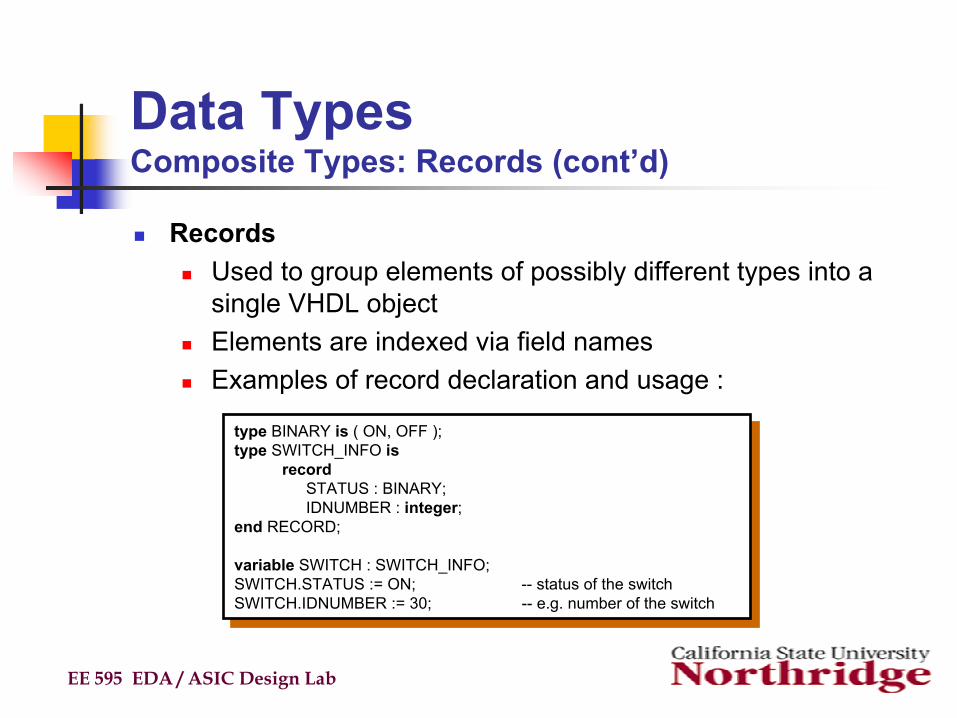
Records Used to group elements of possibly different types into a single VHDL objectElements are indexed via field namesExamples of record declaration and usage :
EE 595 EDA / ASIC Design Lab
type BINARY is ( ON, OFF );type SWITCH_INFO is
recordSTATUS : BINARY;IDNUMBER : integer;
end RECORD;
variable SWITCH : SWITCH_INFO;SWITCH.STATUS := ON; -- status of the switchSWITCH.IDNUMBER := 30; -- e.g. number of the switch
type BINARY is ( ON, OFF );type SWITCH_INFO is
recordSTATUS : BINARY;IDNUMBER : integer;
end RECORD;
variable SWITCH : SWITCH_INFO;SWITCH.STATUS := ON; -- status of the switchSWITCH.IDNUMBER := 30; -- e.g. number of the switch

Data TypesComposite Types: Record Example
EE 595 EDA / ASIC Design Lab
type DELAY_ENTRY isrecord
FALL: TIME;RISE : TIME;
end RECORD;variable DELAY_TIME : DELAY_ENTRY;begin
DELAY_TIME.FALL := 10NSDELAY_TIME.RISE := 12NS;
type DELAY_ENTRY isrecord
FALL: TIME;RISE : TIME;
end RECORD;variable DELAY_TIME : DELAY_ENTRY;begin
DELAY_TIME.FALL := 10NSDELAY_TIME.RISE := 12NS;

Data TypesSubtypes
SubtypeAllows for user defined constraints on a data type e.g. a subtype based on an unconstrained VHDL typeMay include entire range of base typeAssignments that are out of the subtype range are illegalRange violation detected at run time rather than compile time because only base type is checked at compile timeSubtype declaration syntax :
Subtype example :
EE 595 EDA / ASIC Design Lab
subtype NAME is BASE_TYPE range <user range>;subtype NAME is BASE_TYPE range <user range>;
subtype FIRST_TEN is integer range 0 TO 9;subtype FIRST_TEN is integer range 0 TO 9;

Data TypesSubtypes (cont’d)
Subset of a base typeMay contain 1 or all elements of the base typeAllows assignments of elements between base type and subtype that are within the range of the subtypeThe IEEE resolved type ‘std_logic’ is a subtype of the resolved base ‘std_ulogic’Adds constraints to increase usefulness of range checking and minimize number of options in CASE statements
EE 595 EDA / ASIC Design Lab

Data TypesSubtypes (cont’d)
A new subtype can be created by constraining an existing typeExample:
Simulators perform range and type checking during assignmentsMore convenient for frequently used data types (no repeated constraints)Provides for more object oriented design and better documentation
EE 595 EDA / ASIC Design Lab
subtype DIGIT is integer range 0 TO 9;type INSTRUCTION is (ADD, SUB, MUL, DIV, LDA, STA, OUTA, XFR);subtype ARITHMETIC is INSTRUCTION range ADD TO DIV;
subtype BYTE is Bit_Vector(1 TO 8); -- creating an array subtype
subtype DIGIT is integer range 0 TO 9;type INSTRUCTION is (ADD, SUB, MUL, DIV, LDA, STA, OUTA, XFR);subtype ARITHMETIC is INSTRUCTION range ADD TO DIV;
subtype BYTE is Bit_Vector(1 TO 8); -- creating an array subtype
range constraint
Data TypesSummary
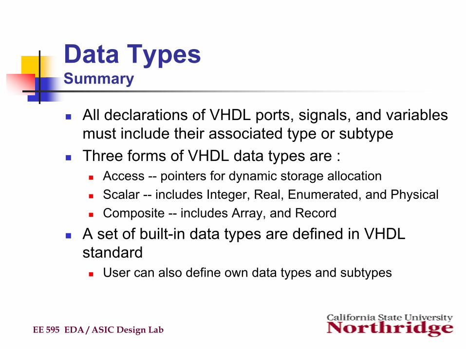
All declarations of VHDL ports, signals, and variables must include their associated type or subtype Three forms of VHDL data types are :
Access -- pointers for dynamic storage allocationScalar -- includes Integer, Real, Enumerated, and PhysicalComposite -- includes Array, and Record
A set of built-in data types are defined in VHDL standard
User can also define own data types and subtypes
EE 595 EDA / ASIC Design Lab

AttributesAttributes provide information about certain items in VHDL, e.g :
Types, subtypes, procedures, functions, signals, variables, constants, entities, architectures, configurations, packages, componentsGeneral form of attribute use :
VHDL has several predefined, e.g :X'EVENT -- TRUE when there is an event on signal XX'LAST_VALUE -- returns the previous value of signal XY'HIGH -- returns the highest value in the range of YX'STABLE(t) -- TRUE when no event has occurred on signal X
in the past ‘t’ time
EE 595 EDA / ASIC Design Lab
NAME'ATTRIBUTE_IDENTIFIER -- read as “tick” NAME'ATTRIBUTE_IDENTIFIER -- read as “tick”
AttributesRegister Example (cont’d)
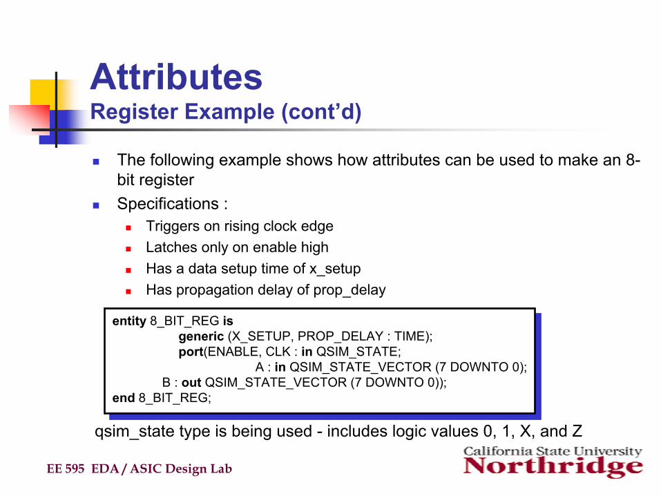
The following example shows how attributes can be used to make an 8-bit registerSpecifications :
Triggers on rising clock edgeLatches only on enable highHas a data setup time of x_setupHas propagation delay of prop_delay
EE 595 EDA / ASIC Design Lab
entity 8_BIT_REG isgeneric (X_SETUP, PROP_DELAY : TIME);port(ENABLE, CLK : in QSIM_STATE;
A : in QSIM_STATE_VECTOR (7 DOWNTO 0); B : out QSIM_STATE_VECTOR (7 DOWNTO 0));
end 8_BIT_REG;
entity 8_BIT_REG isgeneric (X_SETUP, PROP_DELAY : TIME);port(ENABLE, CLK : in QSIM_STATE;
A : in QSIM_STATE_VECTOR (7 DOWNTO 0); B : out QSIM_STATE_VECTOR (7 DOWNTO 0));
end 8_BIT_REG;
qsim_state type is being used - includes logic values 0, 1, X, and Z

Attributes Register Example (cont’d)
The following architecture is a first attempt at the registerThe use of 'STABLE is to used to detect setup violations in the data input
EE 595 EDA / ASIC Design Lab
architecture FIRST_ATTEMPT of 8_BIT_REG isbegin
process (CLK)beginif (ENABLE = '1') and A'STABLE(X_SETUP) and
(CLK = '1') thenB <= A after DELAY;
end if;end process;
end FIRST_ATTEMPT;
architecture FIRST_ATTEMPT of 8_BIT_REG isbegin
process (CLK)beginif (ENABLE = '1') and A'STABLE(X_SETUP) and
(CLK = '1') thenB <= A after DELAY;
end if;end process;
end FIRST_ATTEMPT;
What happens if a does not satisfy its setup time requirement of x_setup?

Attributes Register Example (cont’d)
The following architecture is a second and more robust attempt The use of 'LAST_VALUE ensures the clock is rising from a value of ‘0’
EE 595 EDA / ASIC Design Lab
architecture BEHAVIOR of 8_BIT_REG isbegin
process (CLK)beginif (ENABLE = '1') and A'STABLE(X_SETUP) and
(CLK = '1') and (CLK'LASTVALUE = '0') thenB <= A after DELAY;
end if;end process;
end BEHAVIOR;
architecture BEHAVIOR of 8_BIT_REG isbegin
process (CLK)beginif (ENABLE = '1') and A'STABLE(X_SETUP) and
(CLK = '1') and (CLK'LASTVALUE = '0') thenB <= A after DELAY;
end if;end process;
end BEHAVIOR;
A THEN clause could be added to define the behavior when the requirements are not satisfied

OperatorsOperators can be chained to form complex expressions, e.g. :
Can use parentheses for readability and to control the association of operators and operands
Defined precedence levels in decreasing order :Miscellaneous operators -- **, abs, notMultiplication operators -- *, /, mod, remSign operator -- +, -Addition operators -- +, -, &Shift operators -- sll, srl, sla, sra, rol, rorRelational operators -- =, /=, <, <=, >, >=Logical operators -- AND, OR, NAND, NOR, XOR,
XNOREE 595 EDA / ASIC Design Lab
RES <= A and not(B) or not(A) and B;RES <= A and not(B) or not(A) and B;

Logical Operators
EE 595 EDA / ASIC Design Lab
Operators Definition
and conjunctionor disjunctionxor exclusive disjunctionxnor complement exclusive disjunctionnand complement conjunctionnand complement conjunctionnor complement disjunctionnot complement.
VHDL-93: The predefined logic operator xnor is provided only in VHDL-93.

Logical Operators (cont’d)There are a few rules for evaluating VHDL logic operators that unfortunatelydo not align exactly with switching algebra theory, so it is important to notethem. The and, or, nand and nor logic operators are called short-circuit operators because the right operand is not evaluated if the value of the left operand is not evaluated if the value of the left operand determines the resultof the logic operator. For example, consider the following signals assignmentstatement.
EE 595 EDA / ASIC Design Lab
TEST_SIG <= OPR_A and OPR_B;TEST_SIG <= OPR_A and OPR_B;

OperatorsExamples
EE 595 EDA / ASIC Design Lab
The concatenation operator &
variable SHIFTED, SHIFTIN : Bit_Vector (0 TO 3);...SHIFTED := SHIFTIN(1 TO 3) & '0';
variable SHIFTED, SHIFTIN : Bit_Vector (0 TO 3);...SHIFTED := SHIFTIN(1 TO 3) & '0';
The exponentiation operator **
x := 5**5 -- 5^5 OKy := 0.5**3 -- 0.5^3 OKx := 4**0.5 -- 4^0.5 Illegaly := 0.5**(-2) -- 0.5^(-2) OK
x := 5**5 -- 5^5 OKy := 0.5**3 -- 0.5^3 OKx := 4**0.5 -- 4^0.5 Illegaly := 0.5**(-2) -- 0.5^(-2) OK
1
1 2 3SHIFTIN
SHIFTED
00 0 1
0 0 1 0

OperatorsExamples
EE 595 EDA / ASIC Design Lab
The addition operator + entity ADD isport ( B,C: in Bit; Z: out Bit);
end ADD;architecture RTL of ADD isbegin
Z <= A + B;end RTL;
entity ADD isport ( B,C: in Bit; Z: out Bit);
end ADD;architecture RTL of ADD isbegin
Z <= A + B;end RTL;
Logical Operatorslibrary IEEE;use IEEE.Std_Logic_1164.all;entity MVLS is
port (A, B,C: in Std_Logic; Z: out Std_Logic);end ADD;architecture LOGIC of MVLS isbegin
Z <= A AND NOT (B OR C);end RTL;
library IEEE;use IEEE.Std_Logic_1164.all;entity MVLS is
port (A, B,C: in Std_Logic; Z: out Std_Logic);end ADD;architecture LOGIC of MVLS isbegin
Z <= A AND NOT (B OR C);end RTL;
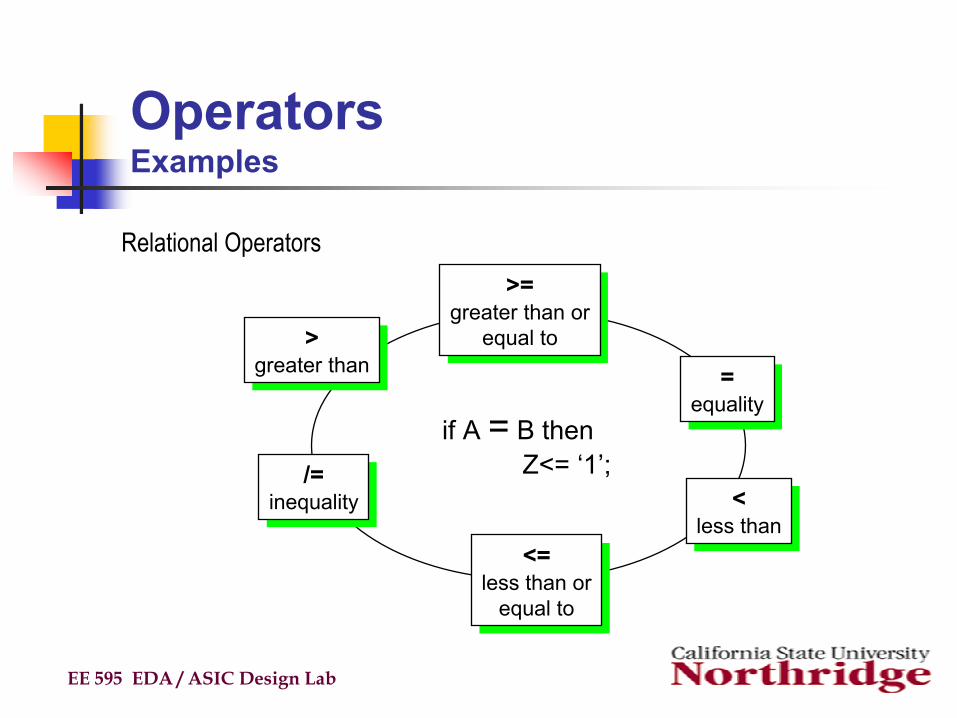
OperatorsExamples
EE 595 EDA / ASIC Design Lab
>=greater than or
equal to
>=greater than or
equal to
<less than
<less than
>greater than
>greater than
/=inequality
/=inequality
<=less than or
equal to
<=less than or
equal to
=equality
=equality
if A = B thenZ<= ‘1’;
Relational Operators

OperatorsQuestions
EE 595 EDA / ASIC Design Lab
Which statements are correct in VHDL?
architecture QUIZ of OPERATORS issignal BOOL : boolean;signal A_INT, B_INT, Z_INT : integer range 0 TO 15;signal Z_BIT : Std_Logic;signal A_VEC, B_VEC, Z_VEC : Std_Logic_Vector (3 DOWNTO 0);
beginZ_BIT <= A_INT = B_INT;BOOL <= A_INT > B_VEC;Z_VEC <= A_VEC & B_VEC;Z_VEC <= A_VEC(1 TO 0) & A_VEC(1 DOWNTO 0);Z_VEC <= A_VEC(1 DOWNTO 0) & B_VEC(1 DOWNTO 0);
end;

SummaryVHDL is a worldwide standard for the description and modeling of digital hardwareVHDL gives the designer many different ways to describe hardwareFamiliar programming tools are available for complex and simple problemsSequential and concurrent modes of execution meet a large variety of design needsPackages and libraries support design management and component reuse
EE 595 EDA / ASIC Design Lab


