25
LGIT LED Lighting Standard Module LGIT LED Lighting Standard Module Application Note RoHS Compliant HALOGEN FREE
LGIT LED Lighting Standard Module
1/25
LGIT LED Lighting Standard Module
Application Note
RoHSCompliant
HALOGEN
FREE

LGIT LED Lighting Standard Module
2/25
CONTENTS
1. Product Description
2. Product Information
2.1. Linear and Square Modules
3. Thermal Management
3.1. Relationship Between Input Current and Contact Temperature (Tc)
4. Output Lumen according to Input Current Increase
5. LM-80 Data
5.1. 6030 PKG LM-80 Data
5.2. 5630 PKG LM-80 Data
6. Design Considerations for Secondary Optics
7. Design Considerations for Diffusers
7.1. Recommended Distance Between the LED Modules and Diffuser Plate
8. Installation Instructions
8.1. Wiring
8.2. Interconnecting Modules
8.3. Connections with Standard Parallel Topology
8.4. Connections with Parallel Topology Leveraging the “opt.” Connector Pole
8.5. Maximum Connections Quantity
8.6. Insulating Washers
8.7. Screw and Torque
8.8. Vf Binning
9. Electrical Characteristics for Multiple LED Module Systems
9.1. Vf Variation Analysis with Multiple LED Module Systems
9.2. Recommended LED Drivers
10. Applications
11. Revision History
3
4
5
9
11
12
12
15
22
24
25

LGIT LED Lighting Standard Module
3/25
1. Product Description
(1) The products (7 different types of modules) are LED modules used for indoor lighting applications.
For more details, refer to Section 10 for the specific applications.
(2) The LG Innotek standard modules are to be mounted on or into a luminaire where an LED driver
may also be mounted on or into the luminaire.
Figure 1 illustrates an example of a combination of the modules and the driver.
In this example, the luminaire holds one LED light engine (LLE) and the LLE has four LED modules.
In practice, the luminaire may hold any number of LLEs with any number of LED modules and
LED drivers, while respecting the maximum current that the LEDs, the connectors and
board traces can support reliably.
(3) The final photometric performance of the luminaire is determined by the number of modules,
the output current from the LED driver, secondary optics/diffusers, and thermal dissipation.
Please refer to the module datasheets to analyze the performance of the respective
module types under various operating conditions.
Luminaire
Module 2 Module 3 Module 4Module 1
Optional Optics (Diffuser)
LED Driver
External Power
Figure 1. Luminaire combination with LED modules and driver

LGIT LED Lighting Standard Module
4/25
2. Product Information
2.1. Linear and Square Modules
Type Items Size Model Number CCT(K)
Linear
Module
CELM-1
280x20
LLFML31-11K201C 3000
LLFML31-11K301C 3500
LLFML31-11K401C 4000
LLFML31-11K601C 5000
CELM-2
280x40
LLFML31-08L201A 3000
LLFML31-08L301A 3500
LLFML31-08L401A 4000
LLFML31-08L601A 5000
CELM-3
280x40
LLFML31-10K201A 3000
LLFML31-10K301A 3500
LLFML31-10K401A 4000
LLFML31-10K601A 5000
CELM-4
280x40
LLFML31-10K201B 3000
LLFML31-10K301B 3500
LLFML31-10K401B 4000
LLFML31-10K601B 5000
CELM-5
560x40
LLFML61-22L201A 3000
LLFML61-22L301A 3500
LLFML61-22L401A 4000
LLFML61-22L601A 5000
Square
Module
CESM-1 270x270
LLFML33-13K201A 3000
LLFML33-13K301A 3500
LLFML33-13K401A 4000
LLFML33-13K601A 5000
CESM-2 270x270
LLFML33-37M201A 3000
LLFML33-37M301A 3500
LLFML33-37M401A 4000
LLFML33-37M601A 5000
LGIT LED Lighting Standard Module
5/25
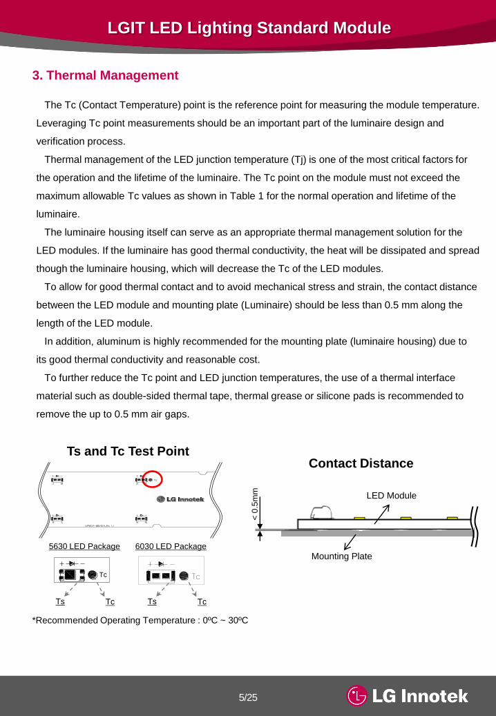
3. Thermal Management
The Tc (Contact Temperature) point is the reference point for measuring the module temperature.
Leveraging Tc point measurements should be an important part of the luminaire design and
verification process.
Thermal management of the LED junction temperature (Tj) is one of the most critical factors for
the operation and the lifetime of the luminaire. The Tc point on the module must not exceed the
maximum allowable Tc values as shown in Table 1 for the normal operation and lifetime of the
luminaire.
The luminaire housing itself can serve as an appropriate thermal management solution for the
LED modules. If the luminaire has good thermal conductivity, the heat will be dissipated and spread
though the luminaire housing, which will decrease the Tc of the LED modules.
To allow for good thermal contact and to avoid mechanical stress and strain, the contact distance
between the LED module and mounting plate (Luminaire) should be less than 0.5 mm along the
length of the LED module.
In addition, aluminum is highly recommended for the mounting plate (luminaire housing) due to
its good thermal conductivity and reasonable cost.
To further reduce the Tc point and LED junction temperatures, the use of a thermal interface
material such as double-sided thermal tape, thermal grease or silicone pads is recommended to
remove the up to 0.5 mm air gaps.
Ts and Tc Test Point
*Recommended Operating Temperature : 0ºC ~ 30ºC
Contact Distance
< 0
.5m
m
Mounting Plate
LED Module
+
LLFML33-13K*01A_Rev 1.1
A1
B10
A19
B28
A37
B46
B2
A11
B20
A29
B38
A47
A3
B12
A21
B30
A39
B48
B4
A13
B22
A31
B40
A49
A5
B14
A23
B32
A41
B50
B6
A15
B24
A33
B42
A51
A7
B16
A25
B34
A43
B52
B8
A17
B26
A35
B44
A53
A9
B18
B27
B36
A45
B54
Tc
Tc
Tc
TcTs TcTs
5630 LED Package 6030 LED Package

LGIT LED Lighting Standard Module
6/25
Table 1. Allowable Maximum Contact Temperature
It is essential that a constant current LED driver be leveraged along with an appropriate amount of
thermal dissipation to maintain the junction and contact temperatures of the LED modules at an
suitable level.
The allowable Max. Tc in Table 1 is defined as the maximum contact temperature while respecting
the maximum module current (If) where the modules are still considered to be working under normal
operating conditions with the expected lumen maintenance characteristics.
For the case of the “LLFML31-11K*01C” product family, a thermal interface material and/or a
mounting plate should be leveraged to reduce the Tc point temperature to 65℃ or under.
Product Model IfMeasured Tc
[ºC]
Measured Ts
[ºC]
Allowable
Max. Tc
[ºC]
LLFML31-11K* 01C 380mA 71.1 72.5
65
LLFML31-08L* 01A 190mA 51.1 55.1
LLFML31-10K* 01A 380mA 55.0 56.9
LLFML31-10K* 01B 380mA 60.2 63.3
LLFML61-22L* 01A 570mA 60.7 61.9
LLFML33-13K* 01A 462mA 37.3 38.0
LLFML33-37M* 01A 760mA 55.5 58.7
*Operating conditions
- Ambient temperature (Ta = 25ºC)
- The boards were being driven in air (No mounting plate or thermal interface material applied)

LGIT LED Lighting Standard Module
7/25
*Operating conditions
- Ambient temperature (Ta = 25ºC)
- The boards were being driven in air (No mounting plate or thermal interface material applied)
• CELM-1 (LLFM31-11K*01C)
• CELM-2 (LLFM31-08L*01A)
• CELM-3 (LLFM31-10K*01A)
3.1. Relationship Between Input Current and Contact Temperature (Tc)
If (mA) Watt (W) Tc (°C) Ts (°C) ΔT (°C) Remark
260 6.14 56.4 57.3 0.92
Ta:25°C320 7.58 63.7 64.9 1.18
380 9.03 71.1 72.5 1.4440
50
60
70
80
90
260 290 320 350 380
Case T
em
pera
ture
[°C
]
Input Current [mA]
LLFML31-11K*01C
280 x 20 (1100lm)
If (mA) Watt (W) Tc (°C) Ts (°C) ΔT (°C) Remark
130 4.62 43.5 46 2.47
Ta:25°C160 5.78 47.3 50.5 3.19
190 6.94 51.1 55.1 3.92
If (mA) Watt (W) Tc (°C) Ts (°C) ΔT (°C) Remark
260 6.11 45.6 46.9 1.29
Ta:25°C320 7.61 50.3 51.9 1.62
380 9.12 55.0 56.9 1.95
30
40
50
60
70
130 140 150 160 170 180 190
Case T
em
pera
ture
[°C
]
Input Current [mA]
LLFML31-08L*01A
280 x 40 (800lm)
30
40
50
60
70
260 280 300 320 340 360 380
Case T
em
pera
ture
[°C
]
Input Current [mA]
LLFML31-10K*01A
280 x 40 (1100lm)

LGIT LED Lighting Standard Module
8/25
• CELM-4 (LLFM31-10K*01B)
• CELM-5 (LLFM61-22L*01A)
• CESM-1 (LLFM33-13K*01A)
• CESM-2 (LLFM33-37M*01A)
If (mA) Watt (W) Tc (°C) Ts (°C) ΔT (°C) Remark
260 7.02 49.7 51.4 1.71
Ta:25°C320 8.67 54.9 57.3 2.36
380 10.33 60.2 63.3 3.02
If (mA) Watt (W) Tc (°C) Ts (°C) ΔT (°C) Remark
390 13.69 49.3 50.3 1.00
Ta:25°C480 17.16 55.0 56.1 1.11
570 20.63 60.7 61.9 1.23
If (mA) Watt (W) Tc (°C) Ts (°C) ΔT (°C) Remark
390 10.33 35.7 36.4 0.61
Ta:25°C426 11.40 36.5 37.2 0.66
462 12.47 37.3 38.0 0.72
If (mA) Watt (W) Tc (°C) Ts (°C) ΔT (°C) Remark
520 23.04 46.2 48.3 2.12
Ta:25°C640 28.73 50.8 53.5 2.66
760 34.43 55.5 58.7 3.19
30
40
50
60
70
260 280 300 320 340 360 380
Case T
em
pera
ture
[°C
]
Input Current [mA]
LLFML31-10K*01B
280 x 40 (1200lm)
30
40
50
60
70
390 420 450 480 510 540 570
Case T
em
pera
ture
[°C
]
Input Current [mA]
LLFML61-22L*01A
560 x 40 (2500lm)
30
32
34
36
38
40
390 402 414 426 438 450 462
Case T
em
pera
ture
[°C
]
Input Current [mA]
LLFML33-13K*01A
270 x 270 (1500lm)
30
40
50
60
70
520 560 600 640 680 720 760
Case T
em
pera
ture
[°C
]
Input Current [mA]
LLFML33-37M*01A
270 x 270 (4000lm)

LGIT LED Lighting Standard Module
9/25
* All values are measured by the LG Innotek integrating sphere with 3000K models.
Measured values are for representative references only.
*Operating conditions
- Ambient temperature (Ta = 25ºC)
- Initial values are measured within 5 seconds
- The boards were being driven in air (No mounting plate or thermal interface material applied)
4. Output Lumen According to Input Current Increase
Input Current Lumen Output lm/W
280x40
1100lm
CELM-3
20mA 63.075 143.3
40mA 122.94 138.9
80mA 241.19 132.1
140mA 412.22 125.1
200mA 570 118.7
240mA 673.57 114.5
300mA 821.31 109.7
380mA 1003.7 103.8
Input Current Lumen Output lm/W
280x20
1100lm
CELM-1
20mA 61.795 140.4
40mA 121.29 137.1
80mA 238.14 130.2
140mA 404.59 122.6
200mA 560.48 116.5
240mA 660.64 112.3
300mA 802.6 107.2
380mA 988.62 101.9
Input Current Lumen Output lm/W
280x40
800lm
CELM-2
10mA 44.568 141.0
20mA 93.983 139.6
40mA 180.85 132.8
70mA 307.19 125.1
100mA 428.31 119.2
120mA 504.45 115.7
150mA 613.83 110.4
190mA 751.63 104.2
0
20
40
60
80
100
20 80 140 200 260 320 380
Rela
tive L
um
ino
us F
lux [
%]
Input Current [mA]
Flux vs Current
Flux Vs. Current
0
20
40
60
80
100
10 40 70 100 130 160 190
Rela
tive L
um
ino
us F
lux [
%]
Input Current [mA]
Flux vs Current
Flux Vs. Current
0
20
40
60
80
100
20 80 140 200 260 320 380
Rela
tive L
um
ino
us F
lux [
%]
Input Current [mA]
Flux vs Current
Flux Vs. Current

LGIT LED Lighting Standard Module
10/25
Input Current Lumen Output lm/W
280x40
1200lm
CELM-4
20mA 70.764 143.3
40mA 138.63 139.5
80mA 272.74 132.8
140mA 463.73 125.1
200mA 642.43 118.9
240mA 758.93 114.6
300mA 922.46 109.6
380mA 1132 103.9
Input Current Lumen Output lm/W
270x270
1500lm
CESM-1
30 mA 100.9 lm 136.8
60 mA 205.0 lm 137.5
120 mA 404.7 lm 133.3
240 mA 790.1 lm 123.9
360 mA 1147.3 lm 116.3
462 mA 1435.5 lm 110.6
Input Current Lumen Output lm/W
270x270
4000lm
CESM-2
40mA 237.0 lm 146.2
80mA 477.0 lm 143.4
160mA 937.5 lm 138.1
280mA 1600.9 lm 129.6
400mA 2216.8 lm 122.5
480mA 2615.4 lm 118.6
600mA 3188.6 lm 113.4
760mA 3879.1 lm 106.7
Input Current Lumen Output lm/W
560x40
2500lm
CELM-5
30mA 143.19 144.3
60mA 286.99 143.0
120mA 559.85 137.2
210mA 952.2 129.1
300mA 1317.7 121.7
360mA 1551.7 117.8
450mA 1893.4 112.6
570mA 2321.2 106.4
0
20
40
60
80
100
20 80 140 200 260 320 380
Rela
tive L
um
ino
us F
lux [
%]
Input Current [mA]
Flux vs Current
Flux Vs. Current
0
20
40
60
80
100
30 90 150 210 270 330 390 450 510 570
Rela
tive L
um
ino
us F
lux [
%]
Input Current [mA]
Flux vs Current
Flux Vs. Current
0
20
40
60
80
100
30 78 126 174 222 270 318 366 414 462
Rela
tive L
um
ino
us F
lux [
%]
Input Current [mA]
Flux vs Current
Flux Vs. Current
0
20
40
60
80
100
40 120 200 280 360 440 520 600 680 760
Rela
tive L
um
ino
us F
lux [
%]
Input Current [mA]
Flux vs Current
Flux Vs. Current

LGIT LED Lighting Standard Module
11/25
* Refer to LED Package Specifications (http://ledlighting.lginnotek.com) for more details.
1) Applied Models
- CELM-1 (LLFML31-11K*01C) - CELM-2 (LLFML31-08L*01A)
- CELM-3 (LLFML31-10K*01A) - CELM-4 (LLFML31-10K*01B)
- CELM-5 (LLFML61-22L*01A) - CESM-2 (LLFML33-37M*01A)
1) Applied Models
- CESM-1 (LLFML33-13K*01A)
• Sample Size : 25ea
• Drive Current : 100mA
• Measurement Current : 100mA
• Temperature Set : 85°C
• Test Duration : 6,000 Hours
2) Results
- Calculated L70 (6K) : 51,000 Hours
- Reported L70 (6K) : >36,000 Hours
• Sample Size : 25ea
• Drive Current : 200mA
• Measurement Current : 200mA
• Temperature Set : 85°C
• Test Duration : 6,000 Hours
2) Results
- Calculated L70 (6K) : 44,000 Hours
- Reported L70 (6K) : >36,000 Hours
5. LM-80 Data
100.0 100.4 100.7 101.3 101.3 100.0
98.5 97.4
90.0
95.0
100.0
105.0
0000 h 500 h 1000 h 2000 h 3000 h 4000 h 5000 h 6000 h
%
Lumen Maintenance(%)
5.1. 6030 LED Package LM-80 Data
5.2. 5630 LED Package LM-80 Data

LGIT LED Lighting Standard Module
12/25
6. Design Considerations for Secondary Optics
7. Design Considerations for Diffusers
Distance between LEDs and a diffuser
Secondary optics such as a lens or reflector should have a clearance of at least 1.0mm from
the LED module (including the LEDs and the connectors).
This is necessary for the functional isolation of the system to prevent short circuits, open circuits,
and physical damage to the components on the board.
Luminaire manufacturers are required to develop or acquire their own diffuser to improve the
luminance uniformity of the system. If multiple LED modules are installed in the luminaire,
a distance of 5.0mm is recommended between the LED modules to allow for a continuous
optical pitch of the LEDs.
If the distance between the LED and diffuser is too short, optical hot spots will be viewable,
which will negatively impact luminance uniformity. However, if the distance is too long, the size
and weight of the luminaire may increase, which may negatively impact cost. The factors for a
diffuser to affect the optimal distance between the LED and diffuser are material, thickness and
clearness (permeability).

LGIT LED Lighting Standard Module
13/25
7.1. Recommended Distance Between the LED Modules and Diffuser Plate
Uniformity
Linear
Type
Model
NumberLLFML31-11K*01C
Uniformity 0.85
Distance* 40mm
Model
NumberLLFML31-08L*01A
Uniformity 0.88
Distance* 70mm
Model
NumberLLFML31-10K*01A
Uniformity 0.87
Distance* 40mm
Model
NumberLLFML31-10K*01B
Uniformity 0.84
Distance* 50mm
Uniformity : 0.85
(Min.11,815 / Max.13,908)
Uniformity : 0.88
(Min.5,556 / Max.6,332)
Uniformity : 0.87
(Min.12,663 / Max.14,522)
Uniformity : 0.84
(Min.9,528 / Max.11,307)

LGIT LED Lighting Standard Module
14/25
• Diffuser Specification
*Distance : Minimum recommended distance from LED to a diffuser for a suitable uniformity factor of over 0.8
• Measurement Condition
Equipment
CA-S20W
Exposure Setting
= 1/128 ND1.5% Normal
Place Dark Room
Sample CCT 3000K
Manufacturer S-POLYTECH
Model LH0555
Thickness (mm) 1.5
Transmittance (%) 76
Haze (%) 98.5
Uniformity
Linear
Type
Model
NumberLLFML61-22L*01A
Uniformity 0.81
Distance* 40mm
Square
Type
Model
NumberLLFML33-13K*01A
Uniformity 0.81
Distance* 60mm
Model
NumberLLFML33-37M*01A
Uniformity 0.81
Distance* 70mm
Uniformity : 0.81
(Min.4,417 / Max.5,429)
Uniformity : 0.81
(Min.11,101 / Max.13,633)
Uniformity : 0.81
(Min.13,977 / Max.16,090)

LGIT LED Lighting Standard Module
15/25
8. Installation Instructions
8.1. Wiring
In the case of a system with multiple interconnected modules, the modules should be connected to
each other leveraging cables with the lengths and wire gauge outlined in this section and Section 8.1.
There are two implementation options for interconnecting the modules.
The first is a simple connection where the “OUT +” connector pole is connected to the “IN +”
connector pole and “OUT –“ connector pole is connected to the “IN –“ connector pole marked
on the PCB.
The other option also leverages the “opt.” connector pole to improve the current balancing from
module to module by reducing the impact of voltage loss from the wire resistance.
However, both options will generate a parallel connection.
8.2. Interconnecting Modules
Connecting the LED driver to the connectors on the LED module should be done with a wire gauge
of 18 ~ 24 AWG and strip length of 6 ~ 7 mm.
See the table and illustrations below for a summary of the specifications.
6 – 7 mm 6 – 7 mm
Strip
Length
Strip
Length
Symbol Function
AWG 18 - 24
Strip Length 6 - 7 mm
Conductor Entry Angle 0° to PCB
Inserting and removing the wire is achieved by
lightly pressing on the connector’s push-button.

LGIT LED Lighting Standard Module
16/25
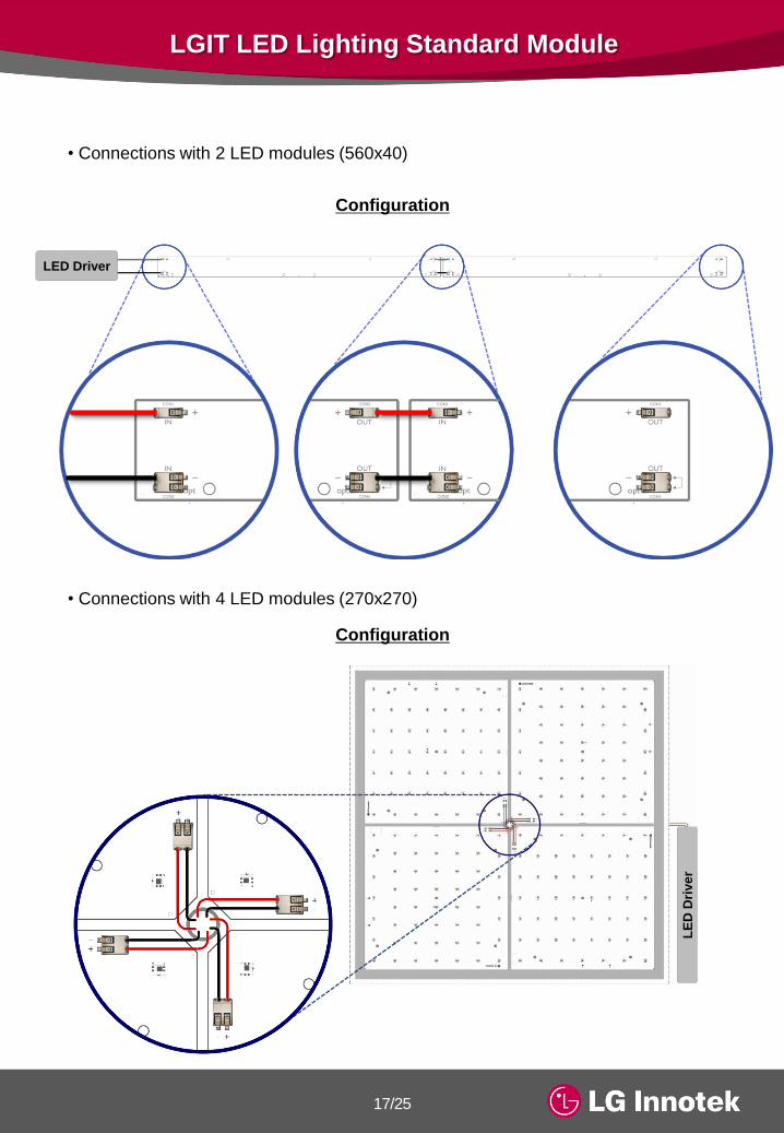
8.3. Connections with Standard Parallel Topology
Configuration
• Connections with 4 LED modules (280x40)
The recommended length of cables for interconnecting the LED modules is summarized
in the table below. The purpose of these lengths is to avoid the blocking of the LED light
by the cable while respecting the recommended 5.0 mm spacing between the modules.
Model Wire Length Remarks
LLFML31-11K*01C 40 ~ 43 mm
6 ~ 7 mm
stripped
at both ends
LLFML31-08L*01A 77 ~ 80 mm
LLFML31-10K*01A 42 ~ 45 mm
LLFML31-10K*01B 77 ~ 80 mm
LLFML61-22L*01A 42 ~ 45 mm
Driver
Wire Length
LED Driver
LED Driver
LGIT LED Lighting Standard Module
17/25
• Connections with 4 LED modules (270x270)
Configuration
Configuration
• Connections with 2 LED modules (560x40)
Driver
LE
D D
rive
r
LED Driver

LGIT LED Lighting Standard Module
18/25
8.4. Connections with Parallel Topology Leveraging the “opt.” Connector Pole
Configuration
Configuration
The use of the “opt.” connector pole improves the current balancing from module
to module by reducing the impact of the voltage drop from the wire resistance.
• Connections with 4 LED modules (280x40)
• Connections with 2 LED modules (560x40)
Driver
DriverLED Driver
LED Driver
LED Driver

LGIT LED Lighting Standard Module
19/25
8.5. Maximum Connections Quantity
• LLFML31-08L*01A (x 4 modules)
LED Driver Module 2 Module 3 Module 4Module 1
• LLFML31-10K*01A (x 4 modules)
LED Driver Module 2 Module 3 Module 4Module 1
LED DriverModule 2 Module 3 Module 4Module 1
• LLFML33-13K*01A (x 4 modules)
• LLFML31-10K*01B (x 4 modules)
LED Driver Module 2 Module 3 Module 4Module 1
LED DriverModule 1
• LLFML33-37M*01A (x 1 module)
• LLFML61-22L*01A (x 2 modules)
LED Driver Module 2Module 1
• LLFML31-11K*01C (x 4 modules)
LED Driver Module 2 Module 3 Module 4Module 1
Product ModelMax. Driver Iout
for 1 Module
Max. Driver Iout
for 2 Modules
Max. Driver Iout
for 3 Modules
Max. Driver Iout
for 4 Modules
Maximum
Connections
Quantity
LLFML31-11K*01C 380 mA 760 mA 1,140 mA 1,520 mA 4 units
LLFML31-08L*01A 190 mA 380 mA 570 mA 760 mA 4 units
LLFML31-10K*01A 380 mA 760 mA 1,140 mA 1,520 mA 4 units
LLFML31-10K*01B 380 mA 760 mA 1,140 mA 1,520 mA 4 units
LLFML61-22L*01A 570 mA 1,140 mA - - 2 units
LLFML33-13K*01A 462 mA 924 mA 1,386 mA 1,848 mA 4 units
LLFML33-37M*01A 760 mA - - - 1 unit

LGIT LED Lighting Standard Module
20/25
Screw Size Materials Min. Torque Max. Torque
Threaded / Tap-tite Screw M4Steel
Aluminum0.6 Nm 1.0 Nm
*Metal screw head diameter should not exceed 9.0 mm for electrical isolation.
The torque depends on the screw type and heat sink or luminaire material.
The screws should be tightened with a torque in accordance with the table below.
8.7. Screw Type and Torque
In order to prevent damage by mounting materials on the
surface of the PCB, the use of insulating washers is highly
recommended when fastening screws.
The electrically isolated layer on the board may be
compromised if washers are not leveraged.
In addition, the mounting materials must comply with
the relevant creepage and clearance guidelines.
8.6. Insulating Washers
• Flat Washers
Material Internal Diameter External Diameter Thickness
Paper / Silicone / Rubber / PTFE etc.
(Any Insulating Washers)4.3 mm 9 mm 0.8 mm
* Washers and Screws are not provided by the LG Innotek

LGIT LED Lighting Standard Module
21/25
8.8. Vf Binning
The LGIT modules are labeled and packaged in two different voltage bins, “O” and “T”.
Connecting modules with different voltage bins in a system may generate current imbalances
between the modules, which may create luminous flux, CCT and temperature imbalances since
the modules are interconnected in parallel.
To solve this problem, LG Innotek recommends that each system comprises of LED modules
from the same Vf bin. The Vf bin is indicated on the PCB, tray and box labels.
All LED modules packaged in a box are from the same Vf bin.
Vf Type Marking on the PCB Label
LED DriverModule 2
(O Type)
Module 3
(O Type)
Module 4
(O Type)
Module 1
(O Type)
LED DriverModule 2
(T Type)
Module 3
(T Type)
Module 4
(T Type)
Module 1
(T Type)
LED Module Combination Example Depending on the Vf Type
H3801000135APTT11T
TLLFM31-11K301C3500K, 1100lm, CRI 80↑
Max. If=380mA, Max. Vf=27V
0001 H3801000135APTT91O
OLLFM31-11K301C3500K, 1100lm, CRI 80↑
Max. If=380mA, Max. Vf=27V
0001
<Example>

LGIT LED Lighting Standard Module
22/25
Module Measured Voltage(V) Module input Current (A)
A 39.20 0.380
B 39.20 0.373
C 39.30 0.372
D 39.60 0.395
Module Measured Voltage(V) Module input Current (A)
A 39.40 0.401
B 39.30 0.378
C 39.10 0.378
D 39.10 0.363
• In the case of leveraging the “opt.” connector pole
9.1. Vf Variation Analysis with Multiple LED Module Systems
• In the case of standard parallel interconnection of the LED modules
△0.038
△0.023
9. Electrical Characteristics for Multiple LED Module Systems

LGIT LED Lighting Standard Module
23/25
9.2. Recommended LED Drivers
929000696103 LED-INTA-1000C-60-DB EUC-042S140DS EUC-052S105DT
Model Driver Power (W) Iout (mA) Flux (lm)Unit Module
Flux (lm)
280x40_1100lm
(x 4modules)
929000696103 37.59 1.4970 4183.6 1045.9
EUC-042S140DS 34.15 1.3730 3902.7 975.7
280x20_1100lm
(x 4modules)
929000696103 37.87 1.4950 4267.9 1067.0
EUC-042S140DS 34.53 1.3730 3982.1 995.5
280x40_1200lm
(x 4modules)929000696103 42.18 1.4940 4645.8 1161.5
280x40_800lm
(x 6modules)
LED-INTA-1000C-60-DB 39.08 1.0440 4512.9 752.2
EUC-052S105DT 38.78 1.0340 4475.1 745.9
560x40_2500lm
(x 2modules)
LED-INTA-1000C-60-DB 38.95 1.0420 4517.2 2258.6
EUC-052S105DT 38.63 1.0350 4470.0 2235.0
270x270_1500lm
(x 4modules)929000696103 40.00 1.4970 4951.3 1237.8
Inventronics InventronicsPhilipsPhilips
• Flux values indicated in the above table were measured by the LG Innotek integrating shpere
with the 3500K models.
• Consider the above values as reference data for your design since they are measured by samples.
The unit module flux value can be different depending on the test conditions.
• Operating conditions
- Ambient temperature (Ta = 25ºC)
- Initial values are measured within 5 seconds
- The boards were being driven in air (No mounting plate or thermal interface material applied)

LGIT LED Lighting Standard Module
24/25
10. Applications
Indoor Lighting
Working area, Study room, Lobby, Lounge, Corridor, Conference room, Meeting area

LGIT LED Lighting Standard Module
25/25
SPECIFICATION
MODEL CELM-1,2,3,4,5 / CESM-1,2 DOCUMENT No. -
REG. DATE 2013. 04. 15 REV. No. Rev. 1.0
REV. DATE - PAGE -
Revision Date Contents of Revision Change Remark
Rev. 1.0 2013.04.15 New Establishment
11. Revision History


