CHAPTER 24.05 LINCOLN GAS PIPING SYSTEMS CODE Sections: 24.05.010 General. 24.05.020 Definitions. 24.05.030 Application for Permit. 24.05.040 Plans and Specifications. 24.05.050 Workmanship. 24.05.060 Inspections. 24.05.070 Certificate of Inspection. 24.05.080 Authority to Render Gas Service. 24.05.090 Authority to Disconnect. 24.05.100 Temporary Use of Gas. 24.05.110 Gas Meter Locations. 24.05.120 Material for Gas Piping. 24.05.130 Installation of Gas Piping. 24.05.140 Appliance Fuel Connectors. 24.05.150 Liquefied Petroleum Gas Facilities and Piping. 24.05.160 Leaks. 24.05.170 Interconnections of Gas Piping Systems. 24.05.180 Required Gas Supply. 24.05.190 Required Gas Piping Size. 24.05.200 Medium- and High-pressure Gas Piping. 24.05.210 Fuel-gas Equipment and Installations in Mobile-home Parks. 24.05.220 Registration Required. 24.05.230 Application. 24.05.240 Examining Board. 24.05.250 Examining Board; Authority. 24.05.260 Examination Required. 24.05.270 Examining Board; Meetings. 24.05.280 Registration of Corporations, Firms, or Partnerships. 24.05.290 Expiration of Registration. 24.05.300 Suspension or Revocation of Certificate of Registration. 24.05.310 Renewal of Certificate of Registration. 24.05.320 Lapsed Registration. 24.05.330 Apprentice; Registration. 24.05.340 Registered Master or Journeyman Gas Fitter Not to Permit Another Person to Work on his Certification. 24.05.350 Registration and Examination Fee. 24.05.360 Certificate of Insurance.
Transcript
CHAPTER 24.05
LINCOLN GAS PIPING SYSTEMS CODE Sections: 24.05.010 General. 24.05.020 Definitions. 24.05.030 Application for Permit. 24.05.040 Plans and Specifications. 24.05.050 Workmanship. 24.05.060 Inspections. 24.05.070 Certificate of Inspection. 24.05.080 Authority to Render Gas Service. 24.05.090 Authority to Disconnect. 24.05.100 Temporary Use of Gas. 24.05.110 Gas Meter Locations. 24.05.120 Material for Gas Piping. 24.05.130 Installation of Gas Piping. 24.05.140 Appliance Fuel Connectors. 24.05.150 Liquefied Petroleum Gas Facilities and Piping. 24.05.160 Leaks. 24.05.170 Interconnections of Gas Piping Systems. 24.05.180 Required Gas Supply. 24.05.190 Required Gas Piping Size. 24.05.200 Medium- and High-pressure Gas Piping. 24.05.210 Fuel-gas Equipment and Installations in Mobile-home Parks. 24.05.220 Registration Required. 24.05.230 Application. 24.05.240 Examining Board. 24.05.250 Examining Board; Authority. 24.05.260 Examination Required. 24.05.270 Examining Board; Meetings. 24.05.280 Registration of Corporations, Firms, or Partnerships. 24.05.290 Expiration of Registration. 24.05.300 Suspension or Revocation of Certificate of Registration. 24.05.310 Renewal of Certificate of Registration. 24.05.320 Lapsed Registration. 24.05.330 Apprentice; Registration. 24.05.340 Registered Master or Journeyman Gas Fitter Not to Permit Another Person to Work on his Certification. 24.05.350 Registration and Examination Fee. 24.05.360 Certificate of Insurance.
24.05.370 Payment Bond. 24.05.380 Permit Fee. 24.05.390 Penalty for Violations. 24.05.010 General. The regulations of this chapter shall govern the installation of fuel gas piping in or in connection with a building or structure or within the property lines of premises, other than service pipe. In addition to any requirements imposed herein, Standards 54 and 58 of the 1992 National Fire Protection Association (NFPA) Standards, as amended from time to time, are hereby adopted and incorporated herein by reference and shall be considered part of this code. One printed copy of the current version of Standard 54 and Standard 58 of the NFPA has been filed in the Office of the City Clerk for use and examination of the public. This ordinance shall be known and cited as the "Lincoln Gas Piping Systems Code" and will be referred to herein as "this code." (Ord. 19822 §1; January 28, 2013: prior Ord. 16542 §1; January 24, 1994). 24.05.020 Definitions. For the purposes of this chapter, certain terms, phrases, words and their derivatives shall be interpreted as set forth in this section; provided, however, that whenever the words "gas meters" appear, they shall be construed to also mean valves and devices required for the regulation of pressure and the measurement of natural gas being dispensed for a building, structure or premises. ADMINISTRATIVE AUTHORITY shall mean the Director of Building and Safety or his authorized representative. APPLIANCE FUEL CONNECTOR shall mean an assembly of listed semirigid or flexible tubing and fittings to carry fuel between a fuel piping outlet and a fuel burning appliance. APPROVED, as to materials, equipment and method of construction, shall mean approval by the Administrative Authority as the result of investigation and tests by the Administrative Authority, or by reason of accepted principles or tests by national authorities, technical or scientific organizations. FUEL GAS shall mean natural, manufactured, liquefied petroleum or a mixture of these. GAS PIPING shall mean an installation of pipe, valves or fittings that is used to convey fuel gas, installed on a premises or in a building, but shall not include: (1) Portions of the service piping. (2) Approved appliance fuel connectors six feet or less in length between an existing gas outlet and a gas appliance in the same room with the outlet. GAS PIPING SYSTEM shall mean an arrangement of gas piping supplied by a single meter or each arrangement of gas piping serving a building, structure or premises, whether individually metered or not. HIGH-DISTRIBUTION PRESSURE or FIRST-STAGE PRESSURE shall mean pressure used in propane vapor systems not exceeding 10 psig. LIQUEFIED PETROLEUM GAS FACILITIES shall mean tanks, containers, container valves, regulating equipment, meters and appurtenances for the storage and supply of liquefied petroleum gas for a building or premises.
MEDIUM PRESSURE shall mean pressure exceeding fourteen inches water column but not exceeding 5 psig. PIPELINE WELDER shall mean a person qualified in welding pipes who holds a valid certificate of competency from an approved agency. QUICK-DISCONNECT DEVICE shall mean a hand-operated device which provides a means for connecting and disconnecting an appliance or an appliance connector to a gas supply. The device is equipped with an automatic means to shut off the gas supply when the device is disconnected. SECOND-STAGE PRESSURE shall mean pressure used in propane vapor systems of 14-inch water columns or less. SERVICE PIPING shall mean the piping and equipment between the street gas main and the gas-piping system inlet which is installed by and is under the control and maintenance of the serving gas supplier. (Ord. 16542 §2; January 24, 1994). 24.05.030 Application for Permit. Every person, firm, or corporation desiring to install, alter, or remove any portion of a gas piping system in any building or upon any premises shall on a form provided by the Administrative Authority make written application therefor to the Administrative Authority. Plans, engineering calculations, diagrams and other data shall be submitted in triplicate with each application for a permit. The Administrative Authority may require plans, computations and specifications to be prepared and designed by an engineer or architect licensed by the state to practice as such. However, the Administrative Authority may waive the submission of plans, calculations or other data if he finds that the nature of the work applied for is such that reviewing of plans is not necessary to obtain compliance with this code. Gas piping system permits shall only be issued to registered master gas fitters. (Ord. 16542 §3; January 24, 1994). 24.05.040 Plans and Specifications. Upon the granting of a permit, the Administrative Authority shall retain one set of the approved plans and specifications of the proposed gas piping system. The Administrative Authority shall file such plans and specifications in his office. The applicant shall keep one set of approved plans and specifications at the site where the work is being done. (Ord. 16542 §4; January 24, 1994). 24.05.050 Workmanship. Gas piping shall not be strained or bent nor shall appliances be supported by or develop strain or stress on supply piping. Gas piping supplying appliances designed to be supported by the piping may be used to support appliances. (Ord. 16542 §5; January 24, 1994). 24.05.060 Inspections. (a) General. Upon completion of installation, alteration or repair of gas piping, and prior to the use thereof, the Administrative Authority shall be notified that gas piping is ready for inspection. (b) Accessibility for Inspection. Excavations required for the installation of underground piping shall be kept open until such time as the piping has been inspected and approved. If piping is covered or concealed before approval, it shall be exposed upon the direction of the Administrative Authority.
(c) Required Inspections. The Administrative Authority shall make the following inspections and shall either approve that portion of the work as completed, or shall notify the permit holder wherein the same fails to comply with this chapter. (1) Rough piping inspection. This inspection shall be made after gas piping authorized by the permit has been installed and before such piping has been covered or concealed or a fixture or appliance has been attached thereto. This inspection shall include a determination that the gas piping size, material and installation meet the requirements of this section. (2) Final piping inspection. This inspection shall be made after piping authorized by the permit has been installed and after all portions thereof which are to be covered or concealed are so concealed and before fixtures, appliances or shutoff valves have been attached thereto. This inspection shall include an air, CO2 or nitrogen pressure test, at which time the gas piping shall stand a pressure of not less than 10-pounds-per-square-inch gauge or not less than one and one-half times the operating pressure or, at the discretion of the Administrative Authority, the piping and valves may be tested at a pressure of at least six inches mercury, measured with a manometer or slope gauge. Test pressures shall be held for a length of time satisfactory to the Administrative Authority but not less than fifteen minutes, with no perceptible drop in pressure. For welded piping, and for piping carrying gas at pressures exceeding fourteen inches water column pressure, the test pressure shall be at least sixty pounds per square inch and shall be continued for a length of time satisfactory to the Administrative Authority but not less than thirty minutes. These tests shall be made using air, CO2 or nitrogen pressure only and shall be made in the presence of the Administrative Authority. Necessary apparatus for conducting tests shall be furnished by the permit holder. (d) Other Inspections. In cases where the work authorized by the permit consists of a minor installation of additional piping to piping already connected to a gas meter or supply tank, the foregoing inspections may be waived at the discretion of the Administrative Authority. The Administrative Authority shall make such inspection as he deems advisable in order to assure that the work has been performed in accordance with the intent of this chapter. (Ord. 16542 §6; January 24, 1994). 24.05.070 Certificate of Inspection. If, upon final piping inspection, the installation is found to comply with the provisions of this chapter, a certificate of inspection may be issued by the Administrative Authority. (Ord. 16542 §7; January 24, 1994). 24.05.080 Authority to Render Gas Service. It shall be unlawful for a person, firm or corporation, excepting an authorized agent or employee of a person, firm or corporation engaged in the business of furnishing or supplying gas and whose service pipes supply or connect with the particular premises, to turn on or reconnect gas service in or on a premises where and when gas service is, at the time, not being rendered. It shall be unlawful to turn on or connect gas in or on a premises unless gas piping outlets are properly and securely connected to gas appliances or capped or plugged with threaded fittings. (Ord. 16542 §8; January 24, 1994).
24.05.090 Authority to Disconnect. (a) General. The Administrative Authority or the serving gas supplier is authorized to disconnect any gas piping or appliance, or both, which is found not to conform to the requirements of this chapter or which is found defective and a danger to life or property. (b) Disconnection Notice. A notice of disconnection shall be attached to defective piping and appliances stating why they have been disconnected. (c) Closing Outlets. It shall be unlawful to remove or disconnect gas piping or a gas appliance without capping or plugging the outlet from which said pipe or appliance was removed with a threaded fitting. Outlets on a piping system which has been installed, altered or repaired to which gas appliances are not connected shall be left capped gastight. EXCEPTION: When an approved listed quick-disconnect device is installed. (Ord. 16542 §9; January 24, 1994). 24.05.100 Temporary Use of Gas. The Administrative Authority may allow temporary use of fuel gas from a gas-piping system conforming to the requirements of this chapter. The period of temporary use shall be established by the Administrative Authority. (Ord. 16542 §10; January 24, 1994). 24.05.110 Gas Meter Locations. (a) General. Gas meter locations shall be approved by the Administrative Authority and the serving gas supplier. (b) Multiple Meters. When more than one meter is set on a premises, they shall all be set at one location, except when this is impractical. In multiple meter installations, each gas-piping system shall be identified by the permittee in a manner satisfactory to the Administrative Authority and the serving gas supplier. (c) Main Shutoff. Gas meters shall be preceded by a main supply shutoff valve and shall be so placed as to be readily accessible for inspection, reading, testing and shutting off the gas supply. Service piping and main supply shutoff valves shall be outside of the building and readily accessible. (d) Inlet Location. The gas piping inlet shall be located adjacent to the approved meter location. (e) Meter Access. Access to enclosed gas meters, except those located in an approved vault supplied by the serving gas supplier, shall be through an opening or door not less in size than 22 inches by 24 inches. (f) Meter Location. Gas meters shall not be located under a show window or under interior stairways or in engine, boiler, heater or electric meter rooms. Where not prohibited by other regulations, gas meters may be located in the open under exterior stairways. (Ord. 16542 §11; January 24, 1994). 24.05.120 Material for Gas Piping. Pipe used for the installation, extension, alteration or repair of gas piping shall be standard weight wrought iron or steel (galvanized or black), yellow brass containing not more than 75 percent copper, or internally tinned or equivalently treated copper of iron pipe size. Approved PE (polyethlene) pipe may be used in exterior buried piping systems when used with factory assembled steel risers.
EXCEPTION: Copper and brass tubing and fittings (except tin-lined copper tubing) shall not be used if the gas contains more than
an average of 0.3 grains of hydrogen sulfide per 100 standard cubic feet of gas (0.7 milligrams per 100 liters).
Gas pipe shall be new or shall have been used previously for no purpose other than conveying gas; it shall be in good condition, clean and free from internal obstructions. Burred ends shall be reamed to the full bore of the pipe. Fittings used in connection with the piping shall be of malleable iron, yellow brass containing not more than 75 percent copper or approved plastic fittings. Valves and appurtenances for gas piping shall be of a type designed and approved for use with fuel gas and AGA approved and stamped. (Ord. 16542 §12; January 24, 1994). 24.05.130 Installation of Gas Piping. (a) Joints. Joints in the piping system, unless welded, shall be threaded joints having approved standard threads or flared joints. Threaded joints shall be made with approved pipe joint material, insoluble in fuel gas and applied to the male threads only. Welded joints in a gas-supply system shall be made by a certified pipeline welder. See Section 24.05.020. (b) Location. Gas piping shall not be installed in or on the ground under any building or structure and exposed gas piping shall be kept at least six inches above grade or structure. Concealed unprotected gas piping may be installed above grade in approved recesses or channels.
EXCEPTION: When necessary due to structural conditions, approved type gas piping may be installed in other locations, when permission has first been obtained from the Administrative Authority.
(c) Drip Pipes. When water vapor is present in the fuel gas served, accessible drip pipes shall be provided at points where condensation will collect. (d) Corrosion and Covering Protection. Ferrous gas piping installed under ground in exterior locations shall be protected from corrosion by approved coatings or wrapping materials applied in an approved manner. Horizontal metallic piping shall have at least twelve inches of earth cover or equivalent protection. Plastic gas piping shall have at least eighteen inches of earth cover or equivalent protection. Risers, including prefabricated risers inserted with plastic pipes, shall be metallic and shall be protected in an approved manner to a point at least six inches above grade. When a riser connects to plastic pipe underground the horizontal metallic portion underground shall be at least thirty inches in length before connecting to the plastic service pipe. An approved transition fitting or adaptor shall be used where the plastic joins the metallic riser. Gas pipe protective coatings shall be approved types, machine applied conforming to recognized standards. Field wrapping shall provide equivalent protection and is restricted to those short sections and fittings necessarily stripped for threading or welding. Zinc coatings (galvanizing) shall not be deemed adequate protection for piping below ground. Ferrous metals exposed in exterior locations shall be protected from corrosion in a manner satisfactory to the Administrative Authority. (e) Corrosion Isolation. Underground ferrous gas piping shall be electrically isolated from the rest of the gas system with listed or approved isolation fittings installed a minimum of six inches above grade. (f) Support and Fill. Gas piping shall be adequately supported by metal straps or hooks at intervals not to exceed those intervals as set out in Table No. 1 at the end of this
chapter. Gas piping installed below grade shall be effectively supported at all points on undisturbed or well-compacted soil or sand. (g) Building Shutoff. Gas piping supplying more than one building on a premises shall be equipped with separate shutoff valves to each building, so arranged that the gas supply can be turned on or off to an individual or separate building. The shutoff valve shall be located outside the building it supplies and shall be readily accessible. Buildings accessory to single-family residences are exempt from the requirements of this subsection. (h) Unions. Groundjoint unions may be used at exposed fixture, appliance, or equipment connections and in exposed exterior locations immediately on the discharge side of a building shutoff valve. Heavy-duty, flanged-type unions may be used. Bushings shall not be in concealed locations. (i) Interjections. When air, oxygen or other special supplementary gas under pressure is introduced with the regularly supplied gas, either directly into the gas piping system or at burners, a device approved by the Administrative Authority shall be installed to prevent backflow of the supplemental gas into the gas-piping system. The device shall be located between the source of the supplemental gas and meter and shall be on the gas line leading to the appliance using the special gas. This device may be either a spring-loaded or diaphragmtype check valve and shall be capable of withstanding the pressure imposed on it. When liquefied petroleum or other standby gas is interconnected with the regular gas-piping system, an approved three-way two-port valve or other adequate safeguard acceptable to the Administrative Authority shall be installed to prevent backflow into either supply system. (j) Valves. Valves used in connection with gas piping shall be approved types, AGA approved and stamped. (k) Barbecue or Fireplace Outlets. Gas outlets in a barbecue or fireplace shall be controlled by an approved operating valve located in the same room and outside the fireplace but not more than four feet from the outlets. If piping on the discharge side of the control valve is standard weight brass, galvanized steel, or black iron pipe, the piping may be embedded in or surrounded by not less than two inches of concrete or masonry. (l) Shutoff Valve. An accessible shutoff valve of a type set forth in Subsection (j) of this section shall be installed in the fuel-supply piping outside of each appliance and ahead of the union connection thereto, and in addition to any valve on the appliance. Shutoff valves shall be within three feet of the appliance. Shutoff valves may be located immediately adjacent to and inside or under an appliance when placed in an accessible and protected location and when such appliance may be removed without removal of the valve. Shutoff valves may be accessibly located inside wall heaters and wall furnaces listed for recessed installation where necessary maintenance can be performed without removal of the shutoff valve. (m) Tracer for Nonmetallic Buried Piping. A No. 18 copper tracer wire or other approved conductor shall be installed with and attached to underground nonmetallic gas piping and shall terminate above grade at each end. (n) Directional Changes. Changes in direction of gas piping shall be made by use of appropriate fittings, except that polyethylene gas piping and tubing may be bent to a radius not less than twenty times the nominal diameter of the pipe or tube. (Ord. 16542 §13; January 24, 1994).
24.05.140 Appliance Fuel Connectors. Appliance connections shall have a diameter not less than that of the inlet connection to the appliance as provided by the manufacturer and each appliance shall be rigidly connected to the gas piping with materials as provided in Section 24.05.120. EXCEPTION: A gas appliance may be connected with an approved listed metal appliance connector under the following conditions:
1. Listed metal appliance connectors shall have an overall length not to exceed three feet, except cooking ranges and laundry equipment connectors, which may not exceed six feet.
2. Connectors shall not be concealed within or extended through wall, floor or partition.
3. A listed appliance connector valve not less than the nominal size of the connector shall be accessible at the gas piping outlet immediately ahead of the connector.
4. Connectors shall be of adequate size to provide the total demand of the connected appliance based on Table No. 2 or 2A as set out at the end of this chapter as applicable.
5. Aluminum alloy connectors may be used only in interior locations where they shall not be in contact with masonry, plaster or insulation or are not subject to repeated corrosive wettings.
6. The connection of an indoor appliance with any type of gas hose is prohibited, except when used for laboratory or shop equipment or equipment that requires mobility during operation. Such connections shall have the shutoff or stopcock installed at the connection to the building piping. When gas hose is used, it shall be of the minimum practical length, but not to exceed six feet, except for hand torches and special mobile equipment, and shall not extend from one room to another nor pass through walls, partitions, ceilings or floors. Gas hose shall not be concealed from view or used in a concealed location. Only listed gas hose shall be used in accordance with its listing. Gas hose shall not be used where it is likely to be subject to temperatures exceeding 125˚F, nor shall it be used as a substitute for a standard appliance connector.
7. Outdoor portable appliances may be connected with an approved outdoor hose connector not to exceed 15 feet in length, provided it connects outdoors to approved gas piping including an approved valve at the inlet of the hose connector.
8. Appliances may be connected to fuel-gas piping with an approved listed quick disconnect device. (Ord. 16542 §14; January 24, 1994).
24.05.150 Liquefied Petroleum Gas Facilities and Piping. In addition to the requirements of this chapter for gas piping, the facilities and piping for use with liquefied petroleum gas shall meet the following requirements: Liquefied petroleum gas facilities shall conform to approved standards. Liquefied petroleum gas facilities and their locations shall be approved by the Administrative Authority and shall conform to state and city fire-prevention regulations. When liquefied petroleum gas facilities serve more than one customer through separate piping systems, each system shall be identified in a manner satisfactory to the Administrative Authority.
Liquefied petroleum gas facilities shall be so placed as to be readily accessible for inspection, reading, testing and shutting off the gas supply. Service piping and main supply shutoff valves shall be outside of the building. Main supply valves shall be of approved type and readily accessible. Gas piping inlets shall be located with respect to the proposed liquefied petroleum gas facility location in accordance with the requirements of this section. Liquefied petroleum gas facilities shall not be located in a pit or basement, under show windows or interior stairways, in engine, boiler, heater or electric meter rooms. When not prohibited by another regulation, approved liquefied petroleum gas metering devices may be located in the open under exterior stairways. Pipejoint compounds used on threaded connections shall be insoluble in liquefied petroleum gas. Valves and appurtenances used in liquefied petroleum gas systems shall be designed and approved for use with liquefied petroleum gas. Discharge from relief valves shall be into open air and shall be at least five feet measured horizontally from an opening into a building which is below the discharge. (Ord. 16542 §15; January 24, 1994). 24.05.160 Leaks. The leakage shall be located by means of an approved combustible gas detector, soap and water, or an equivalent nonflammable solution. Matches, candles, open flames, or other methods that could provide a source of ignition shall not be used. CAUTION: Since some leak test solutions, including soap and water, may cause corrosion or stress cracking, the piping shall be rinsed with water after testing, unless it has been determined the leak test solution is noncorrosive. Where leakage or other defects are located, the affected portion of the piping system shall be repaired or replaced and retested. Flame or acid shall not be used to locate or repair leaks, nor shall sub-stances other than air be introduced into the gas piping. Defective pipe or fitting shall be removed and replaced with approved material. (Ord. 16542 §16; January 24, 1994). 24.05.170 Interconnections of Gas Piping Systems. It shall be unlawful to connect a gas appliance in such a manner that the appliance may receive gas from more than one system of gas piping. The installation, use or maintenance of a gas valve which makes it possible to turn on, control or otherwise direct the flow of gas from one system of gas piping to another, where the systems are supplied with gas from separate meters, is prohibited, and valves or other interconnection between separate systems of gas piping shall be removed upon order of the Administrative Authority. (Ord. 16542 §17; January 24, 1994).
24.05.180 Required Gas Supply. (a) General. Natural gas regulations and tables are based on the use of gas having a specific gravity of 0.60 supplied at six to eight inches water column pressure at the outlet of the meter. For undiluted liquefied petroleum gas, gas piping may be sized for 2500 Btu per cubic foot at eleven inches water column and specific gravity of 1.52. Where gas of a different specific gravity is to be delivered, the serving gas supplier should be contacted for conversion factors or revised capacity tables to use in sizing piping systems. (b) Determining Volume. The hourly volume of gas required at each piping outlet shall be taken as not less than the maximum hourly rating as specified by the manufacturer of the appliance or appliances to be connected to each such outlet. When gas appliances to be installed have not been definitely specified, the minimum demands contained in Table No. 3 as set out at the end of this chapter may be used to estimate requirements of typical appliances. To obtain the cubic feet per hour of gas required, divide Btu per hour input of appliances by the average Btu heating value per cubic foot of the gas. The average Btu per cubic foot of the gas in the area of the installation may be obtained from the serving gas supplier. (c) Minimum Size. The size of the supply piping outlet for a gas appliance shall normally be at least 1/2 inch. The minimum size piping outlet for a mobile home shall normally be 3/4 inch. (Ord. 16542 §18; January 24, 1994). 24.05.190 Required Gas Piping Size. (a) General. When the maximum demand does not exceed 250 cubic feet per hour and the maximum length of piping between the meter and the most distant outlet does not exceed 250 feet, the size of each section and each outlet of any system of gas piping shall be determined by using Table No. 4 or 4A as set out at the end of this chapter as applicable. Other systems within the range of Table No. 4 or 4A, as applicable, may be sized from those tables or by the methods set forth in Subsection (b) of this section. To determine the size of each section of pipe in a system within the range of Table No. 4 or 4A, as applicable, proceed as follows: (1) Measure the length of the pipe from the gas meter location to the most remote outlet on the system. (2) In Table No. 4 or 4A, as applicable, select the column showing that distance, or the next longer distance, if the table does not give the exact length. (3) Starting at the most remote outlet, find in the vertical column just selected, the gas demand for that outlet. If the exact figure of demand is not shown, choose the next larger figure below in the column. (4) Opposite this demand figure, in the first column at the left in Table No. 4, will be found the correct size of pipe. (5) Using this same vertical column, proceed in a similar manner for each section of pipe serving this outlet. For each section of pipe, determine the total gas demand supplied by that section. Where gas piping sections serve both heating and cooling equipment and the installation prevents both units from operating simultaneously, only the larger of the two demand loads need be used in sizing these sections. (6) Size each section of branch piping not previously sized by measuring the distance from the gas meter location to the most remote outlet in that branch and follow the
procedures of steps (2), (3), (4) and (5) above. (Note: Size branch piping in the order of their distance from the meter location, beginning with the most distant outlet not previously sized.) (b) High Demands and Long Runs. For conditions other than those covered by Subsection (a) of this section, such as longer runs or greater gas demands, the size of each gas-piping system shall be determined by standard engineering methods acceptable to the Administrative Authority and each system shall be so designed that the total pressure drop between the meter or other point of supply and any outlet when full demand is being supplied to all outlets will not exceed 0.5-inch water column pressure. (c) Other Systems. When the gas pressure is higher than 14 inches or lower than six inches water column, or when diversity demand factors are used, the design, pipe, sizing, materials, location and use of such systems shall be approved by the Administrative Authority. Piping systems designed for pressures higher than the serving gas supplier's standard delivery pressure shall have prior verification from the gas supplier of the availability of the design pressure. Systems using undiluted liquefied petroleum gas may be sized using Table No. 5 set out at the end of this chapter for eleven inches water column and in accordance with the provisions of Subsections (a) and (b). (Ord. 16542 §19; January 24, 1994). 24.05.200 Medium- and High-pressure Gas Piping. (a) General. Approval of the Administrative Authority and verification from the serving gas supplier of the availability of the desired pressure shall be obtained before any medium- or high-pressure gas-piping system is installed. (b) Applicability. The following requirements shall apply to medium-pressure gas-piping systems. (c) Pressure Regulators. Approved regulators shall be installed on medium- and high-pressure gas-piping systems, in approved locations, and shall be accessible for servicing. Each regulator shall have a separate vent to the outside.
EXCEPTION: Pounds-to-inches water-column regulators equipped with limiting orifices capable of releasing not more than five cubic feet of gas per hour when supplied with medium pressure need not be vented to an outside location when the regulators have been approved by the Administrative Authority. These regulators shall:
1. Be connected to the same piping material used to pipe the structure. A listed gas connector may be used to attach the low-pressure piping downstream of the regulator to the appliance manifold.
2. Have an approved gas valve in the supply line upstream of the pounds-to inches water-column regulator.
3. Be accessible. 4. Have the upstream pressure identified. Such identification shall be an
approved tag permanently attached to the regulator and state: Warning 1/2 to 5 pounds natural gas pressure. DO NOT REMOVE.
5. Be installed in a ventilated area. An approved gas valve shall be installed immediately preceding each regulator. Regulators that may be subjected to mechanical damage shall be substantially protected to the satisfaction of the Administrative Authority. (d) Three or 5 psig. Tables Nos. 6 and 7 set out at the end of this chapter may be used to size a natural gas piping system carrying 3 or 5 psig gas. The procedure to determine the size of each section of the system is similar to that contained in Section 24.05.190 using the pipe
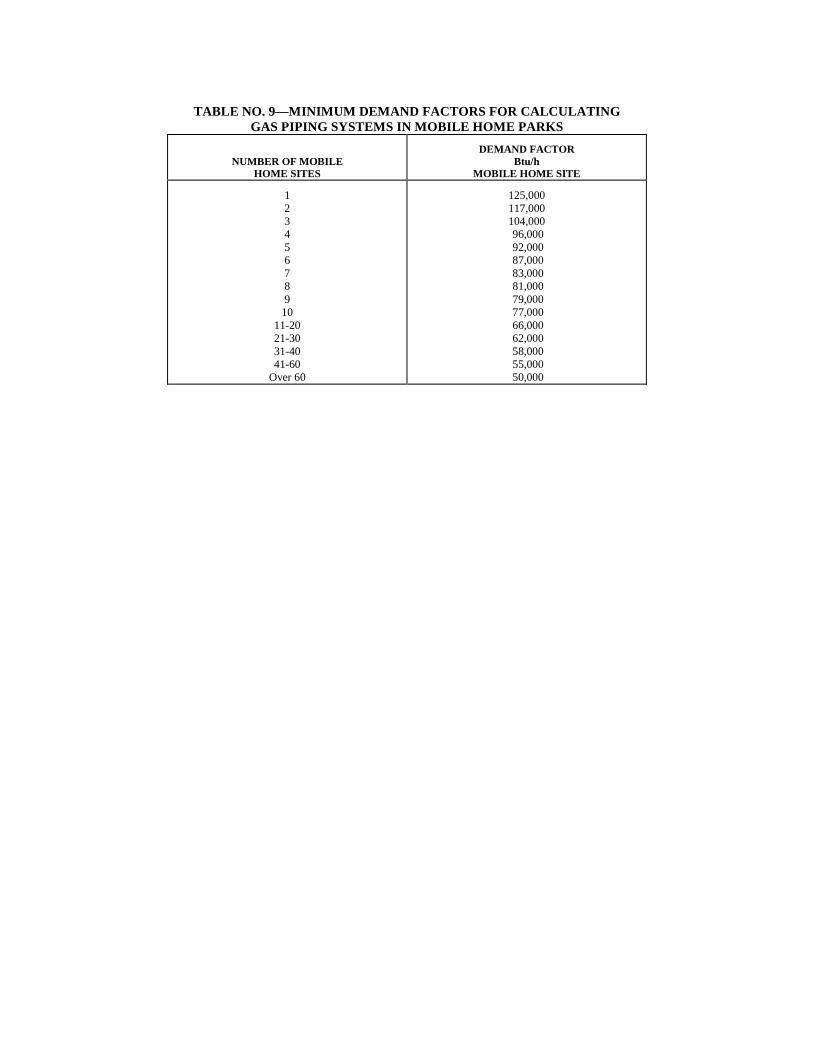
length from the meter to the most remote regulator on the medium- pressure system and sizing the downstream low-pressure piping from Table No. 4 or 4A as applicable. (e) Ten psig. Table No. 8 set out at the end of this chapter may be used to size undiluted liquefied petroleum gas-piping systems carrying 10 psig gas. The procedure to determine the size of each section of the system is similar to Section 24.05.190 using the pipe length from the first stage or tank regulator to the most remote regulator in the second-stage system. Low-pressure piping shall be sized from Table No. 5A or 5B, as set out at the end of this chapter, as applicable. (f) Corrosion and Cover Protection. Buried medium pressure gas piping shall be protected from corrosion as required by Section 24.05.130 and shall have a minimum earth cover of eighteen inches. Piping shall be covered with at least six inches of hand-placed selected backfill devoid of rocks, building materials or other matter that may damage the pipe or wrapping. (Ord. 16542 §20; January 24, 1994). 24.05.210 Fuel-gas Equipment and Installations in Mobile-home Parks. (a) General. Except as otherwise permitted or required by this section, fuel-gas equipment and installations in mobile home parks shall comply with the provisions of this chapter. The provisions of this section do not apply to the mobile home gas piping and equipment. (b) Required Gas Supply. The minimum hourly volume of gas required at each mobile home lot outlet or any section of the mobile home park gas-piping system shall be calculated as set out in Table No. 9 at the end of this chapter. Required gas supply for buildings or other fuel-gas-consuming appliances connected to the mobile home park gas-piping system shall be calculated as provided in this chapter. (c) Installation. Gas piping installed below ground shall have a minimum earth cover of eighteen inches. Gas piping shall not be installed aboveground under a mobile home. (d) Location. Gas piping shall not be installed underground beneath buildings or that portion of the mobile home lots reserved for the location of mobile homes, mobile home accessory buildings or structures, concrete slabs or automobile parking, unless installed in a gastight conduit. The conduit shall be pipe approved for installation underground beneath buildings and not less than Schedule 40 pipe. The interior diameter of the conduit shall be at least 1/2 inch larger than the outside diameter of the gas piping. The conduit shall extend to a point at least twelve inches beyond any area where it is required, or the outside wall of a building, and the outer ends shall not be sealed. When the conduit terminates within a building, it shall be readily accessible and the space between the conduit and the gas piping shall be sealed to prevent leakage of gas into the building. A gas piping lateral terminating in a mobile home lot outlet riser surrounded by a concrete slab shall not be required to be installed in a conduit provided the concrete slab is entirely outside the wall line of the mobile home, is not continuous with any other concrete slab and is used for stabilizing other utility connections. (e) System Shutoff Valve. A readily accessible and identified shutoff valve controlling the flow of gas to the entire gas-piping system shall be installed near the point of connection to the service piping or supply connection of the liquefied petroleum gas tank. (f) Mobile Home Lot Shutoff Valve. Each mobile home lot shall have an approved gas shutoff valve installed upstream of the mobile home lot gas outlet and located on the outlet
riser at a height at least four inches above grade. Such valve shall not be located under a mobile home. When the mobile home lot outlet is not in use, the outlet shall be equipped with an approved cap or plug to prevent accidental discharge of gas. (g) Mobile Home Lot Gas Outlet. Each mobile home lot piped for gas shall be provided with an individual outlet riser at the mobile home lot. The mobile home lot gas outlet shall terminate with the service connection located within a four-foot area in the rear third section of the mobile home lot on the left (road) side of the mobile home, with respect to the location, or proposed location, of the mobile home on the lot. (h) Mobile Home Connector. Each mobile home shall be connected to the mobile home lot outlet by an approved mobile home connector, a maximum of six feet in length. Approved pipe and fittings may be used between the flexible connector and the mobile home lot gas outlet when the distance between the mobile home lot gas outlet and the mobile home gas service connection exceeds that required to make a safe installation with only a mobile home connector. Gas connectors shall be of a size to adequately supply the total demand of the connected mobile home. (i) Mechanical Protection. Gas outlet risers, regulators, meters, valves or other exposed equipment shall be protected from mechanical damage by vehicles or other causes. Such protection may consist of posts, fencing or other permanent barriers. Atmospherically controlled regulators shall be installed in a manner that moisture cannot enter the regulator vent and accumulate above the diaphragm. When the regulator vent may be obstructed by snow or ice, shields, hoods or other suitable devices shall be provided to guard against obstruction of the vent opening. (j) Gas Meters. Meters shall be installed in ventilated or accessible locations not closer than three feet to sources of ignition. When meters are installed, they shall not depend on the gas outlet riser for support, but shall be adequately supported by a post or bracket placed on a firm footing, or other approved means providing equivalent support. (k) Gas Piping Size. The size of each section of natural gas or LP-gas piping systems shall be determined as specified in this chapter. (l) Maintenance. The operator of the mobile home park shall be responsible for maintaining gas piping installations and equipment in a safe working condition. (Ord. 16542 §21; January 24, 1994). 24.05.220 Registration Required. Except as hereinafter provided, no person shall install, alter, modify, or repair a gas piping system, or engage in contracting for such work without first having been registered as a master plumber under the provisions of Chapter 24.12, as a heating, ventilating, and cooling contractor under the provisions of Chapter 25.01 or as a master gas fitter under the provisions of this chapter; provided, however, the employees of a master gas fitter performing work for such master gas fitter pursuant to and within the scope of work permitted by the following registration shall be deemed in compliance with this section. (a) Registration as a journeyman plumber under Chapter 24.12 or registration under this chapter as a journeyman gas fitter entitles the journeyman to install, alter, or repair a gas piping system. (b) Registration as an apprentice plumber under Chapter 24.12 or registration under this chapter as an apprentice gas fitter entitles the apprentice to assist in the installation, repair, or
alteration of a gas piping system under the direct supervision and in the immediate presence of the master or journeyman plumber or the master or journeyman gas fitter. (Ord. 20606 §5; December 11, 2017: prior Ord. 16851 §1; August 14, 1995: Ord. 16542 §22; January 24, 1994). 24.05.230 Application. Application for registration shall be made in writing in the office of the Administrative Authority upon blanks furnished by said authority, which shall show the name and residence of the applicant, the business location of the applicant, and such other information as required by the Administrative Authority to prove the competence of the applicant. (Ord. 16542 §23; January 24, 1994). 24.05.240 Examining Board.
Completed applications for registration shall be submitted to the Examining Board of Plumbers, known as the examining board for this code, for review. Each applicant must take and pass an examination as described in section 24.05.260. (Ord. 20590 §1; December 11, 2017: prior Ord. 19962 §3; December 16, 2013: Ord. 16542 §24; January 24, 1994). 24.05.250 Examining Board; Authority. The examining board shall, subject to the approval of the Mayor, adopt rules and regulations consistent with the provisions of this code for the examination of applicants for registration under the provisions of this code. All decisions of the examining board shall be subject to review by the Mayor upon written request of the aggrieved party. The examining board shall determine minimum qualifications for applicants for registration. (Ord. 20590 §2; December 11, 2017: prior Ord. 16542 §25; January 24, 1994). 24.05.260 Examination Required. Before the applicant shall be registered as a master or journeyman gas fitter, he shall pay an examination fee and submit to an examination to determine his fitness and competency to be registered as a master or journeyman gas fitter, which examination shall be given by the examining board. The examination for master or journeyman gas fitter will be given on such dates and times and at such places as may be determined by the Director of Building and Safety. Reasonable notice of not less than 21 days shall be given. The application, on forms furnished by the Administrative Authority, along with the examination fee, shall be submitted at least two weeks prior to each examination. Upon the payment of the required registration fee, the applicant, after having by said examination shown himself to the satisfaction of the examining board to be fit and competent to be registered as a master or journeyman gas fitter, as the case may be, shall be so registered by the Administrative Authority, who shall deliver to said applicant the respective certificate of registration signed by said Authority. Any applicant who fails to pass the required examination shall not be eligible to take the examination until six months have elapsed. Notwithstanding the above, any person who, prior to the operative date of this ordinance, has been engaged in the occupation of a master gas fitter or journeyman gas fitter shall be granted a registration at his level of qualification as determined by the examining board, without examination, upon payment of the required fee. An applicant for such registration shall submit a written application to the examining board and such evidence as the board may require showing that the applicant is qualified to undertake and safely and properly perform work as a master gas
fitter or journeyman gas fitter. All such applications shall be made to the board within ninety days after the operative date of this ordinance. (Ord. 19822 §2; January 28, 2013: prior Ord. 16542 §26; January 24, 1994). 24.05.270 Examining Board; Meetings. The examining board shall meet as set forth in section 24.12.125. (Ord. 20590 §3; December 11, 2017: prior Ord. 16542 §27; January 24, 1994). 24.05.280 Registration of Corporations, Firms, or Partnerships. Any corporation, firm, or partnership may be registered hereunder as a master gas fitter in the name of such corporation, firm, or partnership; provided, that such corporation, firm, or partnership shall have a master gas fitter who has submitted to the examination given by the examining board and has thereby shown himself fit, competent, and qualified to be registered as a master gas fitter as a bona fide officer or manager of such corporation or a member of such firm or partnership, and who shall at all times be in actual charge of and be responsible for the installation or repair of any and all gas piping system work done by such corporation, firm, or partnership. Before a corporation, firm, or partnership shall be registered in its corporate, firm, or partnership name as a master gas fitter, there shall be filed with the Administrative Authority a certificate from the examining board showing the fitness and competency of such officer or manager of such corporation or such member of such firm or partnership to be a master gas fitter; provided, further, that if after a certificate of registration is issued to such corporation, firm, or partnership, the master gas fitter, as an officer or manager of the corporation or a member of the firm or partnership, shall withdraw therefrom and cease to be connected therewith, then and in that event the Administrative Authority shall forthwith revoke the certificate of registration of such corporation, firm, or partnership. A master gas fitter working for and covered by the insurance of a corporation, firm, or partnership registered under this section is not required to duplicate such coverage under his own insurance policy. (Ord. 16542 §28; January 24, 1994). 24.05.290 Expiration of Registration. All registrations shall expire on the thirty-first day of May following the date thereof, and shall not be assignable. (Ord. 16542 §29; January 24, 1994). 24.05.300 Suspension or Revocation of Certificate of Registration. The Mayor, after hearing as hereinafter specified and upon the recommendations of the Administrative Authority and a report from the examining board, shall have the power to suspend or revoke any master or journeyman gas fitter's certificate of registration if the same was obtained by error or fraud, or if the holder thereof is shown to be no longer qualified, or if such holder fails, neglects, or refuses to comply with the provisions of this code. If suspension or revocation of a certificate of registration is recommended as above provided, the Mayor shall cause written notice to be served upon the registered master or journeyman gas fitter whose registration is recommended for suspension or revocation, setting forth a time and place for a public hearing. Upon the conclusion of such hearing, the Mayor shall within thirty days thereafter render a written decision to such registered master or journeyman gas fitter regarding suspension or revocation of his registration. Such written decision shall be served by mailing it to such registered master or journeyman gas fitter by certified mail at his last known business address or by personal service. If a certificate of
registration is revoked, the holder of the same shall not apply for registration until one year after the date of such revocation. (Ord. 16542 §30; January 24, 1994). 24.05.310 Renewal of Certificate of Registration. Certificates of registration at the time of their expiration may be renewed upon recommendation of the examining board and upon payment of the required annual registration fee. (Ord. 16542 §31; January 24, 1994). 24.05.320 Lapsed Registration. Any person registered under the provisions of this chapter as a master or journeyman gas fitter who does not renew his certificate of registration for a period of sixty days after the expiration of the same shall pay the examination fee required by this chapter for a master or journeyman gas fitter, as the case may be, and shall submit himself to the gas fitter's examination by the examining board before such person can again be registered hereunder. (Ord. 16542 §32; January 24, 1994). 24.05.330 Apprentice; Registration. No person shall engage in any gas piping system work as an apprentice gas fitter unless he has registered with the examining board as a master or journeyman gas fitter's apprentice upon forms prescribed by the Administrative Authority. No registered master or journeyman gas fitter shall employ any person as an apprentice gas fitter who is not so registered. No apprentice gas fitter shall be permitted to work at the installation, alteration, or repair of any gas piping system except under the personal supervision and direction and in the presence of a registered master or journeyman gas fitter. All apprentice gas fitters, after having served two years at such trade, or having equivalent training, may apply for registration as a journeyman gas fitter hereunder and take the required examination. (Ord. 16542 §33; January 24, 1994). 24.05.340 Registered Master or Journeyman Gas Fitter Not to Permit Another Person
to Work on his Certification. No registered master or journeyman gas fitter shall allow his name to be used by another person, directly or indirectly, either to obtain a permit for the installation, repair, or alteration of any gas piping system as hereinafter required, or to do any gas piping system work; and if any registered master or journeyman gas fitter violates this provision, the Administrative Authority shall forthwith recommend revocation of the certificate of registration issued to such person. In addition to having this certificate of registration revoked, such master or journeyman gas fitter may be prosecuted under the penalty section of this chapter for such violation. (Ord. 16542 §34; January 24, 1994). 24.05.350 Registration and Examination Fee. Each applicant for master gas fitter registration or journeyman gas fitter registration shall pay to the Administrative Authority an examination fee as follows: Master gas fitter's examination fee .........................................$50.00 Journeyman gas fitter's examination fee .................................$50.00
Upon initial issuance or subsequent renewal of a registration certificate, a registration fee shall be paid annually to the Administrative Authority as follows: Master gas fitter - annual registration fee ...............................$50.00 Journeyman gas fitter - annual registration fee .......................$25.00 Apprentice gas fitter - annual registration fee.........................$15.00 Any person dealing in gas piping system materials or supplies, but not engaged in the installation, alteration, repair, or removal of gas piping system shall not be required to register hereunder. Such fees shall be paid to the Department of Building and Safety. No fee shall be refunded. (Ord. 19822 §3; January 28, 2013: prior Ord. 16542 §35; January 24, 1994). 24.05.360 Certificate of Insurance. Before any master gas fitter as herein defined may be issued a permit under the provisions of this code, such master gas fitter shall be required to: (a) At all times maintain public liability insurance coverage for all claims arising out of all work in the City of Lincoln and within three miles of the corporate limits thereof done by or under the supervision of the master gas fitter under the provisions of this code. Such insurance shall be in the form of a commercial or comprehensive general liability policy, or an acceptable substitute policy form as permitted by the City Attorney, with a minimum combined single limit of $500,000.00 aggregate for any one occurrence on any job for which a permit is required under this code, provided the City of Lincoln shall be named an additional insured thereunder. The coverages required herein shall be subject to review and approval by the City Attorney for conformance with the provisions of this section. (b) At all times keep on file with the Administrative Authority a current certificate of insurance signed by a qualified agent of an insurance company licensed to do business in the State of Nebraska and approved by the City Attorney for conformance with the provisions of this section evidencing the existence of valid and effective policies of insurance naming the city as an additional insured for the coverage required by subsection (a) of this section, the limits of each policy, the policy number, the name of the insurer, the effective date and expiration date of each policy, the deductibles or self-insurance retainers of each policy, and a copy of an endorsement placed on each policy requiring thirty days notice by mail to the Administrative Authority before the insurer may cancel the policy for any reason, and upon request of the Administrative Authority or the City Attorney, a copy of any endorsements placed on such policies or the declarations page of such policies. Expiration or cancellation of any insurance coverage required by this section shall constitute an automatic and immediate termination of the master gas fitter's privilege to be issued permits under the provisions of this code, unless other insurance meeting the requirements of this section is provided and in full force and effect at the time of such expiration or cancellation. (Ord. 16542 §36; January 24, 1994). 24.05.370 Payment Bond. Before any master gas fitter may be issued a permit to make excavations in the public ways of the city, such master gas fitter shall deposit with the Administrative Authority a $5,000.00 payment bond. Said bond shall provide that the master gas fitter shall pay to the city the cost of refilling such excavation and replacing the surface thereof. Failure to keep charges
for excavation backfill and resurfacing in accordance with Public Works and Utilities Department policy shall be grounds for withholding further permits of any kind until such backlog of charges are paid in full. (Ord. 16951 §149; March 11, 1996: prior Ord. 16542 §37; January 24, 1994). 24.05.380 Permit Fee. The following shall be the permit fees charged in this chapter: New construction (1-5 outlets)......................................... $25.00 Each additional outlet ........................................ 1.00 Replacement with another permit (heating or plumbing) ........................................ 6.00 Replacement alone (with no other permit) ....................................... 35.00 Gas piping alteration .......................................................... 15.00 (Ord. 19822 §4; January 28, 2013: prior Ord. 16542 §38; January 24, 1994). 24.05.390 Penalty for Violations. (a) Any person, firm or corporation violating any of the provisions of this code shall be deemed guilty of a misdemeanor, and each such person shall be deemed guilty of a separate offense for each and every day or portion thereof during which any violation of any of the provisions of this code is committed, continued, or permitted; and upon conviction of any such violation, such person shall be punishable by a fine in any sum not to exceed $500.00, or be imprisoned in the county jail for a period not to exceed six months, or both; except that each person so convicted shall be fined in a sum of not less than $200.00 for the first offense, not less than $250.00 for a second offense, and not less than $300.00 for the third offense and each offense thereafter. (Ord. 16542 §39; January 24, 1994).
TABLE NO. 1—SUPPORT OF PIPING Steel Pipe, Nominal
Size of Pipe (Inches)
Spacing of Supports
(Feet)
Nominal Size of Tubing
(Inch O.D.)
Spacing of Supports
(Feet)
½ 6 ½ 4 ¾ or 1 8 ⅝ or ¾ 6
1¼ or larger (horizontal) 10 ⅞ or 1 8 1¼ or larger
(vertical) every floor
level For SI units: 1 foot = 0.305 m
TABLE NO. 2—
CAPACITIES OF LISTED METAL APPLIANCE CONNECTORS1 For use with gas pressure 8-inch or more water column
SEMI-RIGID CONNECTOR
O.D.2 (Inch)
FLEXIBLE CONNECTOR
NOMINAL I.D.3
(Inch)
MAXIMUM CAPACITIES IN THOUSANDS Btu/h (Based on pressure drop of 0.4-inch water column)
Natural Gas4 of 1100 Btu/cu. ft.
All Gas Appliances Ranges and Domestic Clothes Dryers Only
1Gas connectors are certified by the testing agency as complete assemblies including fittings and valves. Capacities shown are based on the use of fittings and valves supplied with the connector.
2Outside diameter. 3Internal diameter. 4For liquified petroleum gas use 1.6 times the natural gas capacities shown.
TABLE NO. 2A— CAPACITIES OF LISTED METAL APPLIANCE CONNECTORS1
For use with gas pressure less than 8-inch water column
SEMI-RIGID CONNECTOR
O.D.2 (Inch)
FLEXIBLE CONNECTOR
NOMINAL I.D.3
(Inch)
CAPACITIES FOR VARIOUS LENGTHS IN THOUSANDS Btu/h (Based on pressure drop of 0.2-inch water column)
Natural Gas4 of 1100 Btu/cu. ft.
All Gas Appliances Ranges and Domestic Clothes Dryers Only
1Gas connectors are certified by the testing agency as complete assemblies including fittings and valves. Capacities shown are based on the use of fittings and valves supplied with the connector.
2Outside diameter. 3Internal diameter. 4For liquified petroleum gas use 1.6 times the natural gas capacities shown.
APPLIANCE DEMAND
_______________________________________________________________________________________ Domestic gas range ............................................................................ 65,000 Domestic recessed top burner section ................................................ 40,000 Domestic recessed oven section ........................................................ 25,000 Storage water heater—up to 30-gal. tank .......................................... 30,000 Storage water heater—40 to 50-gal. tank .......................................... 50,000 Domestic clothes dryer ...................................................................... 35,000 Fireplace log lighter (residential) ....................................................... 25,000 Fireplace log lighter (commercial) .................................................... 50,000 Barbecue (residential) ........................................................................ 50,000 Gas refrigerator .................................................................................. 3,000 Bunson burner .................................................................................... 3,000 Mobile homes .................................................................................. 1 Gas engines (per horsepower) ............................................................. 10,000 Steam boilers (per horsepower) ........................................................... 50,000
1See Table 9.
TABLE NO. 3—MINIMUM DEMAND OF TYPICAL GAS APPLIANCES Btu/h
TABLE NO. 4—SIZE OF GAS PIPING
Maximum Delivery Capacity in Cubic Feet of Gas Per Hour of I.P.S. Pipe Carrying Natural Gas of 0.60 Specific Gravity Based on 0.5-inch Water Column Pressure Drop
Length in Ft. 1/4 3/8 1/2 5/8 3/4 1 1 1/4 1 1/2 2 2 1/2 3 4
Chart 2: For 6-inch Water Column Pressure Pipe Cfh at 1-inch Pressure Drop— .65 Gravity Gas— Nominal Pipe or I.D. Tubing Size
TABLE NO. 6—MEDIUM-PRESSURE NATURAL GAS SYSTEM For Sizing Gas Piping Carrying Gas of 0.60 Specific Gravity Capacity of Pipes of Different Diameters and
Lengths in Cubic Feet per Hour for Gas Pressure of 3.0 psi with a Drop to 1.5 psi PIPE SIZE
TABLE NO. 7—MEDIUM-PRESSURE NATURAL GAS SYSTEM For Sizing Gas Piping Carrying Gas of 0.60 Specific Gravity Capacity of Pipes of Different Diameters and
Lengths in Cubic Feet per Hour for Gas Pressure of 5.0 psi with a Drop to 1.5 psi PIPE SIZE
TABLE NO. 8—FOR PROPANE GAS PRESSURE OF 10.0 psi WITH MAXIMUM PRESSURE DROP OF 3.0 psi Maximum Delivery Capacity in Cubic Feet of Gas per Hour of I.P.S. Pipe of Different Diameters
and Lengths Carrying Propane Gas of 1.52 Specific Gravity