46
Load Balancing Microsoft Lync 2010 / 2013 Deployment Guide v1.7.2 Copyright © Loadbalancer.org
Load Balancing Microsoft Lync2010 / 2013
Deployment Guidev1.7.2
Copyright © Loadbalancer.org
Table of Contents
1. About this Guide.........................................................................................................................................4
2. Loadbalancer.org Appliances Supported..........................................................................................4
3. Loadbalancer.org Software Versions Supported............................................................................4
4. Microsoft Lync Software Versions Supported.................................................................................4
5. Microsoft Lync.............................................................................................................................................5Microsoft Lync Editions........................................................................................................................................................ 5
Standard Edition.................................................................................................................................................................. 5
Enterprise Edition................................................................................................................................................................ 5
6. Microsoft Lync & Loadbalancer.org.....................................................................................................5
7. Microsoft Lync Server Roles....................................................................................................................5
8. Load Balancing Lync.................................................................................................................................7Load Balancing Methods Supported................................................................................................................................ 7
DNS Load Balancing........................................................................................................................................................... 7
Hardware Load Balancing (HLB).................................................................................................................................... 8
Load Balanced Roles............................................................................................................................................................. 8
Loadbalancer.org Appliance Considerations................................................................................................................8
Load Balancer Deployment Mode................................................................................................................................ 8
Persistence (aka Server Affinity)..................................................................................................................................... 9
TCP Timeout Settings....................................................................................................................................................... 9
Reverse Proxy Server......................................................................................................................................................... 9
Additional Details................................................................................................................................................................... 9
9. Load Balanced Ports/Protocols..........................................................................................................10Front End Servers................................................................................................................................................................. 10
Required.............................................................................................................................................................................. 10
Optional............................................................................................................................................................................... 10
Director Servers..................................................................................................................................................................... 11
Required............................................................................................................................................................................... 11
Optional............................................................................................................................................................................... 11
Edge Servers (Internal Access).......................................................................................................................................... 11
Edge Servers (External Access)......................................................................................................................................... 11
10. Deployment Architecture...................................................................................................................12Loadbalancer.org test Environment............................................................................................................................... 12
One-arm Vs Two-arm......................................................................................................................................................... 13
Front End Pool – the Details............................................................................................................................................. 14
Director Pool – the Details................................................................................................................................................ 15
Internal Edge – the Details................................................................................................................................................ 16
External Edge – the Details............................................................................................................................................... 17
Lync Topology Builder....................................................................................................................................................... 18
DNS Configuration.............................................................................................................................................................. 18
11. Loadbalancer.org Appliance – the Basics.....................................................................................19Virtual Appliance Download & Deployment............................................................................................................... 19
Initial Network Configuration.......................................................................................................................................... 19
Accessing the Web User Interface (WebUI)................................................................................................................20
Microsoft Lync 2010/2013 Deployment Guide v1.7.2
HA Clustered Pair Configuration..................................................................................................................................... 21
12. Appliance Configuration for Lync....................................................................................................22STEP 1 – Configure Layer 7 Global Settings................................................................................................................ 22
STEP 2 – Configuring the Load Balanced Front End Services...............................................................................22
Virtual Service (VIP) List.................................................................................................................................................. 22
Configuring the FrontEndPool VIP............................................................................................................................. 23
Configuring the FePoolExtWebSvcs8080 VIP........................................................................................................24
Configuring the FePoolExtWebSvcs4443 VIP........................................................................................................25
STEP 3 – Configuring the Load Balanced Director Services..................................................................................29
Virtual Service (VIP) List.................................................................................................................................................. 29
Configuring the DirectorPool VIP............................................................................................................................... 29
Configuring the DirPoolExtWebSvcs8080 VIP.......................................................................................................30
Configuring the DirPoolExtWebSvcs4443 VIP........................................................................................................31
STEP 4 – Configuring the Load Balanced Edge Pool Services (Internal)...........................................................35
Virtual Service (VIP) List.................................................................................................................................................. 35
Virtual Service (VIP) Configuration............................................................................................................................. 35
Real Server (RIP) Configuration................................................................................................................................... 36
STEP 5 – Configuring the Load Balanced Edge Pool Services (External)...........................................................37
Virtual Service (VIP) List.................................................................................................................................................. 37
Virtual Service (VIP) Configuration.............................................................................................................................. 37
Real Server (RIP) Configuration................................................................................................................................... 38
STEP 6 – Finalizing the Configuration.......................................................................................................................... 38
13. Testing & Validation..............................................................................................................................39Client connections bypass the load balancer............................................................................................................ 39
Taking Servers Offline........................................................................................................................................................ 39
Microsoft Lync Testing Tool............................................................................................................................................. 39
Lync Diagnostics Tools...................................................................................................................................................... 39
Wireshark Protocol Analyzer........................................................................................................................................... 40
Other Useful Resources..................................................................................................................................................... 40
14. Technical Support.................................................................................................................................40
15. Further Documentation......................................................................................................................40
16. Conclusion...............................................................................................................................................40
17. Appendix....................................................................................................................................................411 – Clustered Pair Configuration – Adding a Slave Unit..........................................................................................41
2 – Configure Reverse Proxy VIPs.................................................................................................................................. 43
3 - Company Contact Information................................................................................................................................ 46
Microsoft Lync 2010/2013 Deployment Guide v1.7.2
About this Guide
1. About this GuideThis guide details the steps required to configure a load balanced Microsoft Lync 2010 / 2013 environmentutilizing Loadbalancer.org appliances. It covers the configuration of the load balancers and also any Microsoft Lync 2010 / 2013 configuration changes that are required to enable load balancing.
For more information about initial appliance deployment, network configuration and using the Web User Interface (WebUI), please also refer to the relevant Administration Manual:
• v7 Administration Manual
• v8 Administration Manual
2. Loadbalancer.org Appliances SupportedDue to the number of Virtual Services (VIPs) required for Lync, the Enterprise R16 & R20 are not supported. All other models can be used with Lync as listed below:
Discontinued Models Current Models *
Enterprise VA Enterprise MAX
Enterprise R320 Enterprise 10G
Enterprise Ultra
Enterprise VA MAX
Enterprise AWS
* For full specifications of these models please refer to: http://www.loadbalancer.org/products/hardware
3. Loadbalancer.org Software Versions Supported
• V7.6.4 and later
4. Microsoft Lync Software Versions Supported
• Microsoft Lync 2010 – all versions
• Microsoft Lync 2013 – all versions
Microsoft Lync 2010/2013 Deployment Guide v1.7.2
Page 4
Microsoft Lync
5. Microsoft LyncMicrosoft Lync is an Enterprise level real-time communications server, providing the infrastructure for enterprise instant messaging, presence, file transfer, peer-to-peer and multiparty voice and video calling, ad-hoc and structured conferences (audio, video and web) and PSTN (Public Switched Telephone Network) connectivity. These features are available within an organization, between organizations, and with external users on the public internet, or standard phones, using the PSTN or via SIP trunking.
MICROSOFT LYNC EDITIONS
STANDARD EDITIONStandard Edition server is designed for small organizations, and for pilot projects of large organizations. It enables many of the features of Lync, including the necessary databases, to run on a single server. This enables you to have Lync Server functionality for a lesser cost, but does not provide a true high-availabilitysolution.
ENTERPRISE EDITIONFor a high-availability solution Lync Enterprise Edition is required. Load balancing is required to load balance the Front End pools, Director pools and Edge Server pools.
6. Microsoft Lync & Loadbalancer.orgDeploying Microsoft Lync with Loadbalancer.org appliances enables organizations to create a feature rich highly resilient solution that ensures that wherever staff are located and however they connect, they can depend on a platform that allows seamless communications wherever and whenever needed using the communications medium of their choice.
Loadbalancer.org appliances are configured to present a series of Virtual Services (VIPs). These VIPs become the connection points for internal and external clients. The load balancer is then able to distributerequests to the Lync servers that make up the various pools.
7. Microsoft Lync Server RolesSystem functionality is split into multiple roles as shown in the following table. For the Standard edition, allroles are installed on a single server, for the Enterprise edition, roles can be distributed across multiple servers depending on the number of end-users, server performance and HA requirements.
The table also summarizes the scalability, HA & co-location options for each role.
Role Details
Front End Server Purpose: As the core server role, the Front End Server runs many Lync Server services. This role along with the back-end SQL server are the minimum required roles for Lync.
Scalability: Each front end server can support up to 10,000 users. When configured in a pool, up to 80,000 users are supported.
High Availability: Use a pool of servers with a load balancer.
Microsoft Lync 2010/2013 Deployment Guide v1.7.2
Page 5
Microsoft Lync Server Roles
Back End Server Purpose: The back-end SQL Server hosts various databases to keep track of Lync's configuration and state information.
Scalability: Microsoft recommends using an SQL cluster for high availability.
High Availability: Use clustering/Mirroring techniques.
A/V Conferencing Server
Purpose: Provides Audio/Visual conferencing functionality to Lync clients.
Scalability: Microsoft recommends a separate dedicated server for more than 10,000users. Each dedicated A/V server supports up to 20,000 users.
High Availability: Use a pool of servers (no load balancer is required).
Co-location: By default this role is co-located with the Front End Server, but can also be deployed separately.
Edge Server Purpose: Enables users to communicate and collaborate with users outside the organization’s firewalls. These external users can include the organization’s own users who are currently working off-site, users from federated partner organizations,and outside users who have been invited to join conferences hosted on your Lync Server deployment. This role also enables connectivity to public IM connectivity services, including Windows Live, AOL, and Yahoo!.
Scalability: One Edge Server for every 15,000 users who will access a site remotely. As a minimum, Microsoft recommend two Edge Servers for high availability.
High Availability: Use a pool of servers with a load balancer.
Mediation Server Purpose: Enables Enterprise Voice and dial-in conferencing. Mediation Server translates signaling and, in some configurations, media between your internal Lync Server infrastructure and a public switched telephone network (PSTN) gateway, IP-PBX, or a Session Initiation Protocol (SIP) trunk.
Scalability: A dedicated Mediation Server supports up to 1200 users. Co-located witha Front End Server, it supports up to 226 users.
High Availability: Use a pool of servers with a load balancer.
Co-location: By default this role is co-located with the Front End Server, but can also be deployed separately, which for larger deployments making a large number of calls is recommended.
Monitoring Server Purpose: This role collects data from the Lync infrastructure and allows administrators to run reports. This information can help to provide the best possible media experience for users and maximize the return on investment of your deployment as well as helping to plan future growth.
Scalability: One physical Monitoring Server can support up to 250,000 users if not co-located with Archiving Server. If co-located, it can support up to 100,000 users.
High Availability: Use a standby server (messages are queued on the Front-End
Microsoft Lync 2010/2013 Deployment Guide v1.7.2
Page 6
Microsoft Lync Server Roles
servers if a failure occurs).
Co-location: Can be co-located with Archiving Server.
Archiving Server Purpose: Enables archiving of IM communications and meeting content for compliance reasons. If you do not have legal compliance concerns, you do not need to deploy Archiving Server.
Scalability: One physical Archiving Server can support up to 500,000 users if not co-located with Monitoring Server. If co-located, it can support up to 100,000 users.
High Availability: Use a standby server (messages are queued on the Front-End servers if a failure occurs).
Co-location: Can be co-located with Monitoring Server.
Director Server Purpose: This is a required role when Edge Servers are deployed. In this case Director authenticates the external users, and then passes their traffic on to the internal servers. Directors are also deployed with Front End pools to streamline authentication requests and improve performance. In this scenario, all requests go first to the Director, which then routes them to the correct Front End pool.
Scalability: One Director for every 15,000 users who will access a site remotely. As a minimum, Microsoft recommend two Directors for high availability.
High Availability: Use a pool of servers with a load balancer.
8. Load Balancing Lync
Note:
It's highly recommended that you have a working Lync environment first before implementing the load balancer.
LOAD BALANCING METHODS SUPPORTEDMicrosoft Lync supports two types of load balancing solutions: Domain Name System (DNS) load balancing and Hardware Load Balancing (HLB).
DNS LOAD BALANCINGLync DNS load balancing is typically implemented at the application level. When the application (for example, a Lync client) queries DNS for the pool members IP address, all member addresses are returned. Then, the client attempts to establish a TCP connection to one of the IP addresses. If that fails, the client tries the next IP address in the cache. If the TCP connection succeeds, the client negotiates TLS to connectto the Front End Server. If it gets to the end without a successful connection, the user is notified that no servers running Lync Server are available at the moment.
It's not possible to use DNS load balancing for client to server HTTP/HTTPS traffic because these are session state oriented protocols. In this case a Hardware Load Balancer must be used.
Microsoft Lync 2010/2013 Deployment Guide v1.7.2
Page 7
Load Balancing Lync
HARDWARE LOAD BALANCING (HLB)As mentioned above, hardware based load balancing is required for Web traffic. Therefore it's possible to use a HLB in a hybrid mode where the HLB balances web traffic and DNS load balancing is used for all other services, or in exclusive mode where the HLB is used to balance all services.
Note:
The configuration presented in this manual uses hardware load balancing for all load balanced services.
LOAD BALANCED ROLESThe following pools/servers require load balancing:
The Enterprise Pool with multiple Front End Servers: The hardware load balancer serves as the connectivity point to multiple Front End Servers in an Enterprise pool. For Web Services, the simple URLs can either be directed at the Front End Servers or the Director Servers. However, when Director Servers aredeployed then it is recommend that these requests are forwarded to the Director Pool.
The Director Pool with multiple Director Servers: The hardware load balancer serves as the connectivity point to multiple Directors in an array and also for the external Web Services typically forwarded from a DMZ based Reverse Proxy such as Microsoft TMG.
The Edge Pool with multiple Edge Servers: The hardware load balancer acts as the connectivity point to both the internal and external NICs for multiple Edge Servers in an array. Different hardware load balancerscan be used to load balance Edge Servers, one for the internal NICs and one for the external NICs of the Edge Server.
LOADBALANCER.ORG APPLIANCE CONSIDERATIONS
LOAD BALANCER DEPLOYMENT MODEDirect Return (DR) mode aka Direct Server Return (DSR) mode is not supported for Lync. Modes that are supported are as follows:
• Full-NAT mode (also known as proxy, secure NAT, source NAT, or SNAT mode). In full-NAT mode, both the source and IP destinations are changed as packets pass through the load balancer.
Note:
Loadbalancer.org refer to this mode as 'Layer 7 SNAT mode'
• Half-NAT mode (also known as transparency, destination NAT or DNAT mode). In half-NAT mode, the destination IP address is changed as packets pass through the load balancer, but the source IP address remains intact.
Note:
Loadbalancer.org refer to this mode as 'Layer 4 NAT mode'
The following table describes the supported configurations for full-NAT and half-NAT modes:
Microsoft Lync 2010/2013 Deployment Guide v1.7.2
Page 8
Load Balancing Lync
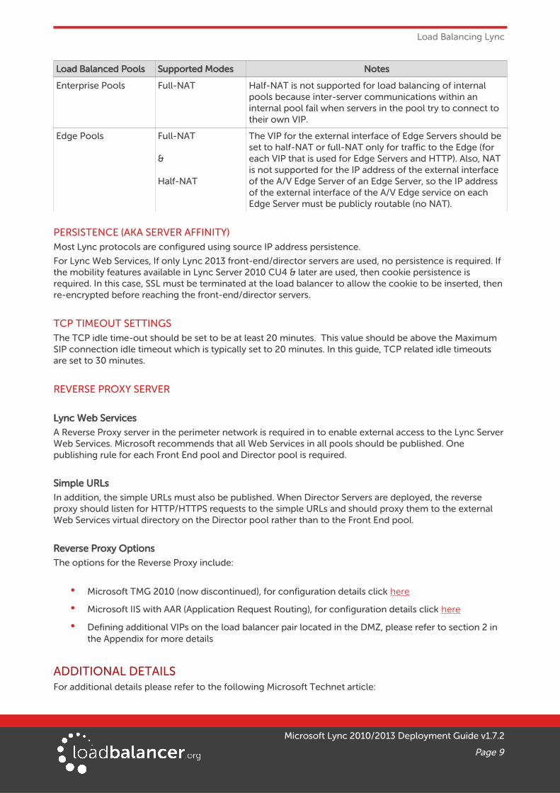
Load Balanced Pools Supported Modes Notes
Enterprise Pools Full-NAT Half-NAT is not supported for load balancing of internal pools because inter-server communications within an internal pool fail when servers in the pool try to connect to their own VIP.
Edge Pools Full-NAT
&
Half-NAT
The VIP for the external interface of Edge Servers should be set to half-NAT or full-NAT only for traffic to the Edge (for each VIP that is used for Edge Servers and HTTP). Also, NAT is not supported for the IP address of the external interface of the A/V Edge Server of an Edge Server, so the IP address of the external interface of the A/V Edge service on each Edge Server must be publicly routable (no NAT).
PERSISTENCE (AKA SERVER AFFINITY)Most Lync protocols are configured using source IP address persistence.
For Lync Web Services, If only Lync 2013 front-end/director servers are used, no persistence is required. If the mobility features available in Lync Server 2010 CU4 & later are used, then cookie persistence is required. In this case, SSL must be terminated at the load balancer to allow the cookie to be inserted, then re-encrypted before reaching the front-end/director servers.
TCP TIMEOUT SETTINGSThe TCP idle time-out should be set to be at least 20 minutes. This value should be above the Maximum SIP connection idle timeout which is typically set to 20 minutes. In this guide, TCP related idle timeouts are set to 30 minutes.
REVERSE PROXY SERVER
Lync Web Services
A Reverse Proxy server in the perimeter network is required in to enable external access to the Lync Server Web Services. Microsoft recommends that all Web Services in all pools should be published. One publishing rule for each Front End pool and Director pool is required.
Simple URLs
In addition, the simple URLs must also be published. When Director Servers are deployed, the reverse proxy should listen for HTTP/HTTPS requests to the simple URLs and should proxy them to the external Web Services virtual directory on the Director pool rather than to the Front End pool.
Reverse Proxy Options
The options for the Reverse Proxy include:
• Microsoft TMG 2010 (now discontinued), for configuration details click here
• Microsoft IIS with AAR (Application Request Routing), for configuration details click here
• Defining additional VIPs on the load balancer pair located in the DMZ, please refer to section 2 in the Appendix for more details
ADDITIONAL DETAILSFor additional details please refer to the following Microsoft Technet article:
Microsoft Lync 2010/2013 Deployment Guide v1.7.2
Page 9
Load Balancing Lync
Reverse Proxy Servers:
2010: https://technet.microsoft.com/en-us/library/gg398069(v=ocs.14).aspx
2013: https://technet.microsoft.com/en-us/library/gg398069(v=ocs.15).aspx
Lync Load Balancing Requirements:
2010: https://technet.microsoft.com/en-us/library/gg615011(v=ocs.14).aspx
2013: https://technet.microsoft.com/en-us/library/gg615011(v=ocs.15).aspx
Components Required for External User Access:
2010: https://technet.microsoft.com/en-us/library/gg425779(v=ocs.14).aspx
2013: https://technet.microsoft.com/en-us/library/gg425779(v=ocs.15).aspx
9. Load Balanced Ports/Protocols
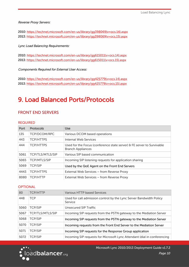
FRONT END SERVERS
REQUIRED
Port Protocols Use
135 TCP/DCOM/RPC Various DCOM based operations
443 TCP/HTTPS Internal Web Services
444 TCP/HTTPS Used for the Focus (conference state server) & FE server to Survivable Branch Appliances
5061 TCP/TLS/MTLS/SIP Various SIP based communication
5065 TCP/MTLS/SIP Incoming SIP listening requests for application sharing
5069 TCP/SIP Used by the QoE Agent on the Front End Servers
4443 TCP/HTTPS External Web Services – from Reverse Proxy
8080 TCP/HTTP External Web Services – from Reverse Proxy
OPTIONAL
80 TCP/HTTP Various HTTP based Services
448 TCP Used for call admission control by the Lync Server Bandwidth Policy Service
5060 TCP/SIP Unsecured SIP Traffic
5067 TCP/TLS/MTLS/SIP Incoming SIP requests from the PSTN gateway to the Mediation Server
5068 TCP/SIP Incoming SIP requests from the PSTN gateway to the Mediation Server
5070 TCP/SIP Incoming requests from the Front End Server to the Mediation Server
5071 TCP/SIP Incoming SIP requests for the Response Group application
5072 TCP/SIP Incoming SIP requests for Microsoft Lync Attendant (dial in conferencing
Microsoft Lync 2010/2013 Deployment Guide v1.7.2
Page 10
Load Balanced Ports/Protocols
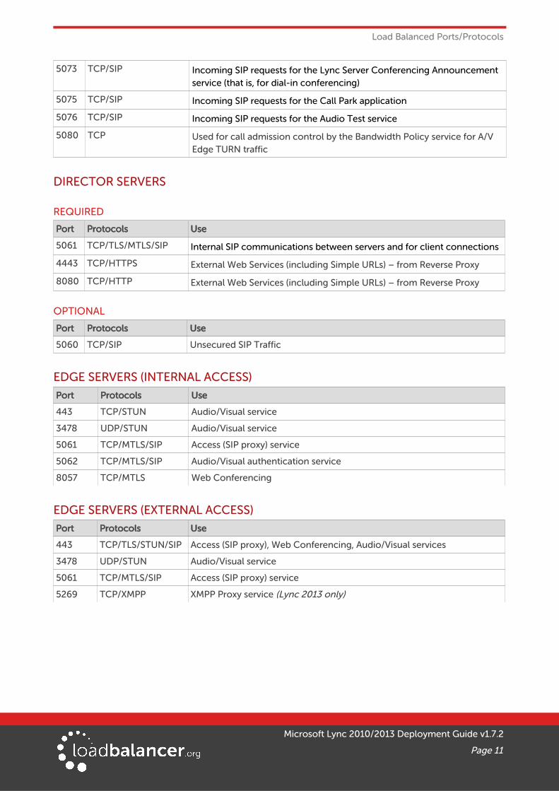
5073 TCP/SIP Incoming SIP requests for the Lync Server Conferencing Announcement service (that is, for dial-in conferencing)
5075 TCP/SIP Incoming SIP requests for the Call Park application
5076 TCP/SIP Incoming SIP requests for the Audio Test service
5080 TCP Used for call admission control by the Bandwidth Policy service for A/V Edge TURN traffic
DIRECTOR SERVERS
REQUIRED
Port Protocols Use
5061 TCP/TLS/MTLS/SIP Internal SIP communications between servers and for client connections
4443 TCP/HTTPS External Web Services (including Simple URLs) – from Reverse Proxy
8080 TCP/HTTP External Web Services (including Simple URLs) – from Reverse Proxy
OPTIONAL
Port Protocols Use
5060 TCP/SIP Unsecured SIP Traffic
EDGE SERVERS (INTERNAL ACCESS)
Port Protocols Use
443 TCP/STUN Audio/Visual service
3478 UDP/STUN Audio/Visual service
5061 TCP/MTLS/SIP Access (SIP proxy) service
5062 TCP/MTLS/SIP Audio/Visual authentication service
8057 TCP/MTLS Web Conferencing
EDGE SERVERS (EXTERNAL ACCESS)
Port Protocols Use
443 TCP/TLS/STUN/SIP Access (SIP proxy), Web Conferencing, Audio/Visual services
3478 UDP/STUN Audio/Visual service
5061 TCP/MTLS/SIP Access (SIP proxy) service
5269 TCP/XMPP XMPP Proxy service (Lync 2013 only)
Microsoft Lync 2010/2013 Deployment Guide v1.7.2
Page 11
Load Balanced Ports/Protocols
Note:
For further details on server port requirements please also refer to the following Microsoft links:
For Front End & Director Servers: http://technet.microsoft.com/en-us/library/gg398833.aspx
For Edge Servers: http://technet.microsoft.com/en-us/library/gg398739.aspx
Lync Protocol Workload Poster: http://www.microsoft.com/download/en/details.aspx?id=6797
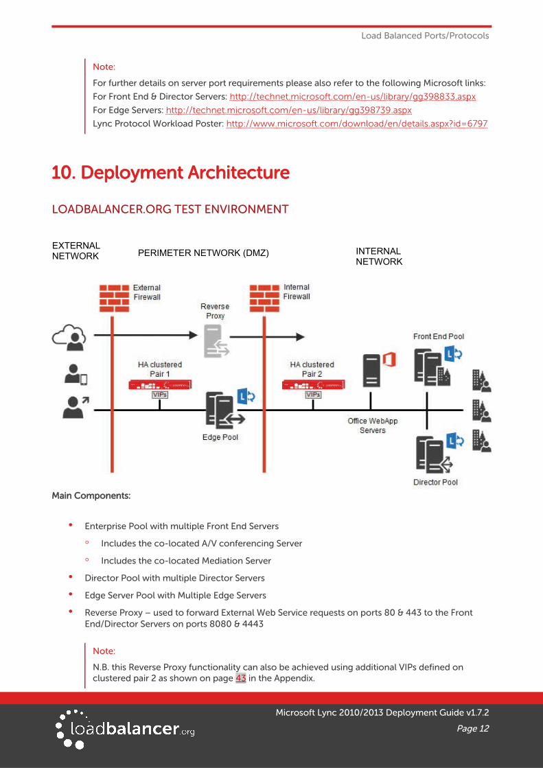
10. Deployment Architecture
LOADBALANCER.ORG TEST ENVIRONMENT
Main Components:
• Enterprise Pool with multiple Front End Servers
◦ Includes the co-located A/V conferencing Server
◦ Includes the co-located Mediation Server
• Director Pool with multiple Director Servers
• Edge Server Pool with Multiple Edge Servers
• Reverse Proxy – used to forward External Web Service requests on ports 80 & 443 to the Front End/Director Servers on ports 8080 & 4443
Note:
N.B. this Reverse Proxy functionality can also be achieved using additional VIPs defined on clustered pair 2 as shown on page 43 in the Appendix.
Microsoft Lync 2010/2013 Deployment Guide v1.7.2
Page 12
EXTERNALNETWORK PERIMETER NETWORK (DMZ) INTERNAL
NETWORK
Deployment Architecture
• Load Balancer Clustered Pair 1 – Used to load balance the Internal Edge, the Director Servers and the Enterprise Front End Servers
• Load Balancer Clustered Pair 2 – Used to load balance the External Edge
Notes:
• The load balancers are deployed in two-arm mode , but this can changed if desired depending on your network topology – see page 13 for more details
ONE-ARM VS TWO-ARMThe options available depend on the load balancing method used and the network topology. In this guide services are deployed using both layer 7 SNAT mode and layer 4 NAT mode.
Layer 7 SNAT Mode
For layer 7 services, both one-arm and two-arm can be used without any problem. This is because layer 7 works as a reverse proxy and client requests are always comprised of 2 connections, i.e.:
Client <----> Load Balancer
and
Load Balancer <----> Back-end Server
Therefore, clients can be located on the same subnet as the Load balancer or on a different subnet or network without any issue, provided that network routing is configured correctly.
Layer 4 NAT Mode
For Layer 4 NAT mode, unlike layer 7 SNAT mode, the client source IP address is maintained right through to the servers (i.e. it's transparent). This means that the client location must be considered to ensure that NAT mode works correctly. The main point to consider is that return traffic from server to client must pass via the load balancer.
For a two-arm configuration where clients are located in the same subnet as one arm of the load balancer,and the load balanced servers are located on the same subnet as the other arm of the load balancer, the load balanced servers default gateway must be set to be the load balancer and everything will work.
For a one-arm configuration, it depends where the clients are located in relation to the load balanced servers. One-arm layer 4 NAT mode for Lync will only work if the clients are located in remote subnets/networks, and the default gateway on the load balanced servers is set to be the load balancer. If clients are located on the same subnet as the load balanced servers, this will not work.
This Deployment Guide
In this guide, both load balancer pairs are deployed in two-arm mode.
Microsoft Lync 2010/2013 Deployment Guide v1.7.2
Page 13
Deployment Architecture
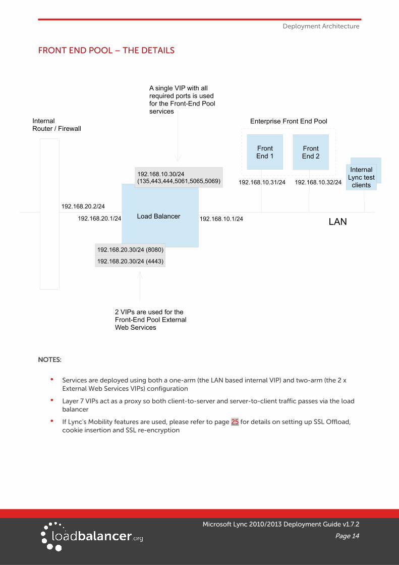
FRONT END POOL – THE DETAILS
NOTES:
• Services are deployed using both a one-arm (the LAN based internal VIP) and two-arm (the 2 x External Web Services VIPs) configuration
• Layer 7 VIPs act as a proxy so both client-to-server and server-to-client traffic passes via the load balancer
• If Lync's Mobility features are used, please refer to page 25 for details on setting up SSL Offload, cookie insertion and SSL re-encryption
Microsoft Lync 2010/2013 Deployment Guide v1.7.2
Page 14
InternalRouter / Firewall
LAN192.168.10.1/24Load Balancer192.168.20.1/24
192.168.20.2/24
A single VIP with all required ports is used for the Front-End Pool services
FrontEnd 1
FrontEnd 2
InternalLync test
clients
192.168.10.30/24(135,443,444,5061,5065,5069)
192.168.20.30/24 (4443)
192.168.20.30/24 (8080)
2 VIPs are used for the Front-End Pool External Web Services
192.168.10.32/24192.168.10.31/24
Enterprise Front End Pool
Deployment Architecture
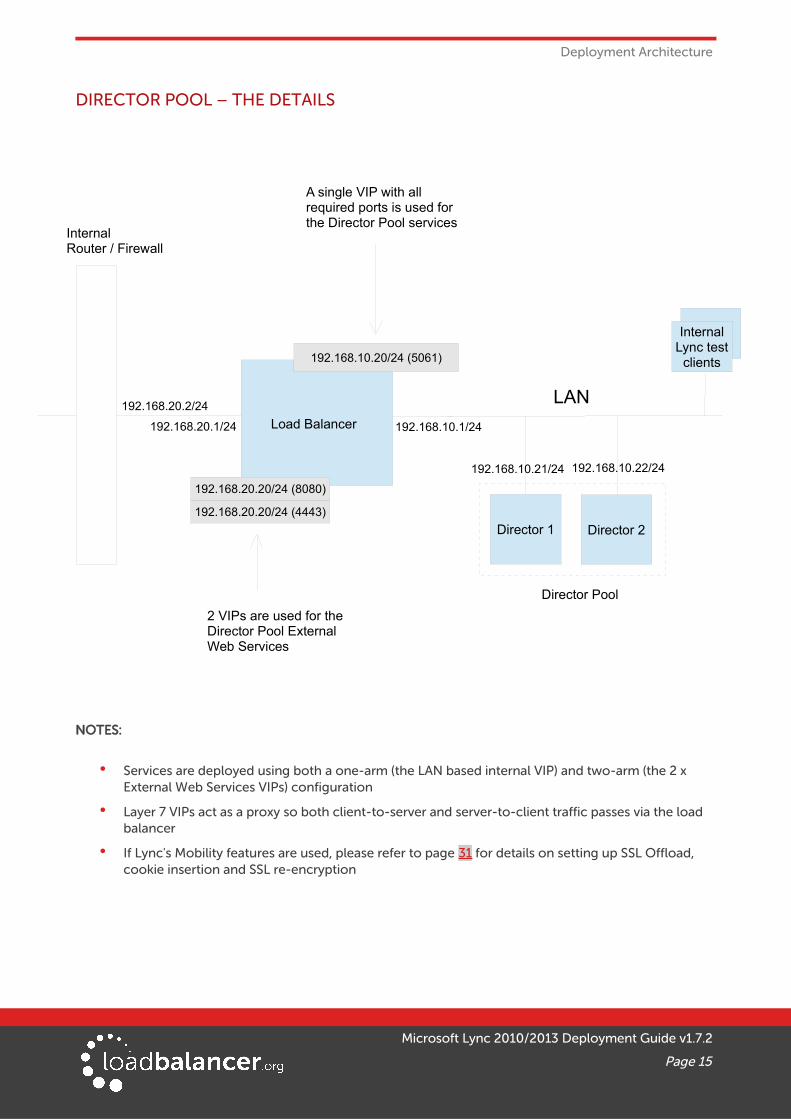
DIRECTOR POOL – THE DETAILS
NOTES:
• Services are deployed using both a one-arm (the LAN based internal VIP) and two-arm (the 2 x External Web Services VIPs) configuration
• Layer 7 VIPs act as a proxy so both client-to-server and server-to-client traffic passes via the load balancer
• If Lync's Mobility features are used, please refer to page 31 for details on setting up SSL Offload, cookie insertion and SSL re-encryption
Microsoft Lync 2010/2013 Deployment Guide v1.7.2
Page 15
InternalRouter / Firewall
LAN
192.168.10.1/24Load Balancer192.168.20.1/24
192.168.20.2/24
A single VIP with all required ports is used for the Director Pool services
Director 1 Director 2
InternalLync test
clients
192.168.20.20/24 (4443)
192.168.20.20/24 (8080)
2 VIPs are used for the Director Pool External Web Services
192.168.10.21/24 192.168.10.22/24
Director Pool
192.168.10.20/24 (5061)
Deployment Architecture
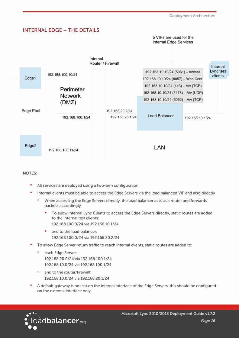
INTERNAL EDGE – THE DETAILS
NOTES:
• All services are deployed using a two-arm configuration
• Internal clients must be able to access the Edge Servers via the load balanced VIP and also directly
◦ When accessing the Edge Servers directly, the load balancer acts as a router and forwards packets accordingly
▪ To allow internal Lync Clients to access the Edge Servers directly, static routes are added to the internal test clients:
192.168.100.0/24 via 192.168.10.1/24
▪ and to the load balancer:
192.168.100.0/24 via 192.168.20.2/24
• To allow Edge Server return traffic to reach internal clients, static routes are added to:
◦ each Edge Server:
192.168.20.0/24 via 192.168.100.1/24
192.168.10.0/24 via 192.168.100.1/24
◦ and to the router/firewall:
192.168.10.0/24 via 192.168.20.1/24
• A default gateway is not set on the internal interface of the Edge Servers, this should be configuredon the external interface only
Microsoft Lync 2010/2013 Deployment Guide v1.7.2
Page 16
InternalRouter / Firewall
Edge2 LAN
Perimeter Network(DMZ)
Edge Pool
Edge1
192.168.10.1/24
192.168.100.10/24
192.168.100.11/24
Load Balancer192.168.20.1/24
192.168.20.2/24
5 VIPs are used for the Internal Edge Services
192.168.100.1/24
InternalLync test
clients192.168.10.10/24 (5061) – Access
192.168.10.10/24 (443) – A/v (TCP)
192.168.10.10/24 (3478) – A/v (UDP)
192.168.10.10/24 (5062) – A/v (TCP)
192.168.10.10/24 (8057) – Web Conf.
Deployment Architecture
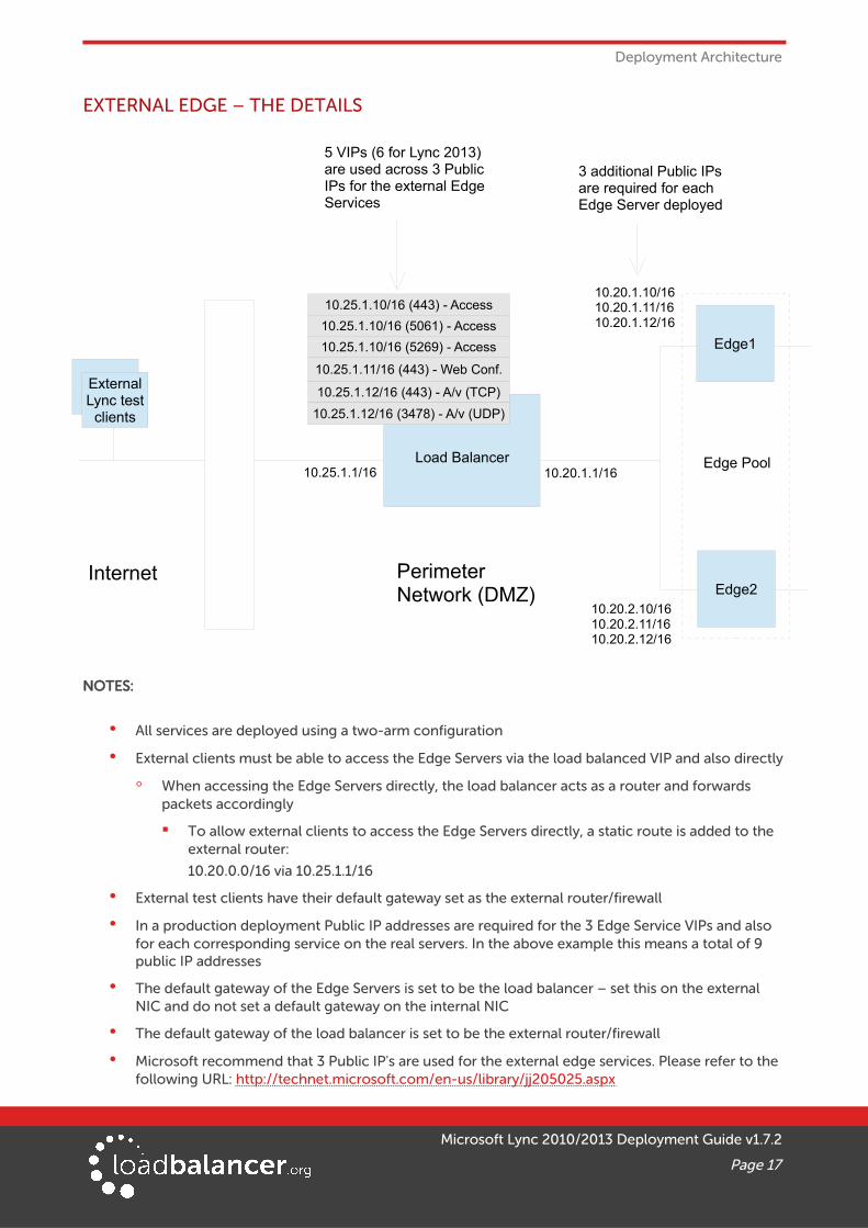
EXTERNAL EDGE – THE DETAILS
NOTES:
• All services are deployed using a two-arm configuration
• External clients must be able to access the Edge Servers via the load balanced VIP and also directly
◦ When accessing the Edge Servers directly, the load balancer acts as a router and forwards packets accordingly
▪ To allow external clients to access the Edge Servers directly, a static route is added to the external router:
10.20.0.0/16 via 10.25.1.1/16
• External test clients have their default gateway set as the external router/firewall
• In a production deployment Public IP addresses are required for the 3 Edge Service VIPs and also for each corresponding service on the real servers. In the above example this means a total of 9 public IP addresses
• The default gateway of the Edge Servers is set to be the load balancer – set this on the external NIC and do not set a default gateway on the internal NIC
• The default gateway of the load balancer is set to be the external router/firewall
• Microsoft recommend that 3 Public IP's are used for the external edge services. Please refer to the following URL: http://technet.microsoft.com/en-us/library/jj205025.aspx
Microsoft Lync 2010/2013 Deployment Guide v1.7.2
Page 17
Edge2Internet Perimeter
Network (DMZ)
10.25.1.12/16 (443) - A/v (TCP)
10.25.1.11/16 (443) - Web Conf.
10.25.1.10/16 (443) - Access
5 VIPs (6 for Lync 2013) are used across 3 Public IPs for the external Edge Services
Edge Pool
Edge1
10.20.1.1/16
10.20.2.10/1610.20.2.11/1610.20.2.12/16
10.20.1.10/1610.20.1.11/1610.20.1.12/16
Load Balancer10.25.1.1/16
10.25.1.12/16 (3478) - A/v (UDP)
10.25.1.10/16 (5061) - Access
ExternalLync test
clients
3 additional Public IPs are required for each Edge Server deployed
10.25.1.10/16 (5269) - Access
Deployment Architecture
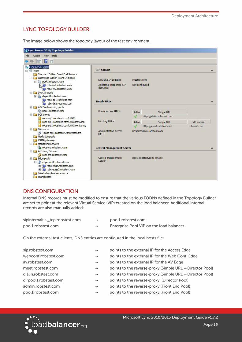
LYNC TOPOLOGY BUILDER
The image below shows the topology layout of the test environment.
DNS CONFIGURATIONInternal DNS records must be modified to ensure that the various FQDNs defined in the Topology Builder are set to point at the relevant Virtual Service (VIP) created on the load balancer. Additional internal records are also manually added:
sipinternaltls._tcp.robstest.com pool1.robstest.com→pool1.robstest.com Enterprise Pool VIP on the load balancer→
On the external test clients, DNS entries are configured in the local hosts file:
sip.robstest.com → points to the external IP for the Access Edge
webconf.robstest.com → points to the external IP for the Web Conf. Edge
av.robstest.com → points to the external IP for the AV Edge
meet.robstest.com → points to the reverse-proxy (Simple URL Director Pool)→dialin.robstest.com → points to the reverse-proxy (Simple URL Director Pool)→dirpool1.robstest.com → points to the reverse-proxy (Director Pool)
admin.robstest.com → points to the reverse-proxy (Front End Pool)
pool1.robstest.com → points to the reverse-proxy (Front End Pool)
Microsoft Lync 2010/2013 Deployment Guide v1.7.2
Page 18
Loadbalancer.org Appliance – the Basics
11. Loadbalancer.org Appliance – the Basics
VIRTUAL APPLIANCE DOWNLOAD & DEPLOYMENTA fully featured, fully supported 30 day trial is available if you are conducting a PoC (Proof of Concept) deployment. The VA is currently available for VMware, Virtual Box, Hyper-V, KVM and XEN and has been optimized for each Hypervisor. By default, the VA is allocated 1 CPU, 2GB of RAM and has an 8GB virtual disk. The Virtual Appliance can be downloaded here.
Note:
The same download is used for the licensed product, the only difference is that a license key file(supplied by our sales team when the product is purchased) must be applied using the appliance's WebUI.
Note:
Please refer to the Administration Manual and the ReadMe.txt text file included in the VA download for more detailed information on deploying the VA using various Hypervisors.
INITIAL NETWORK CONFIGURATIONThe IP address, subnet mask, default gateway and DNS settings can be configured in several ways as detailed below:
Method 1 - Using the Network Setup Wizard at the console
After boot up, follow the instructions on the console to configure the IP address, subnet mask, default gateway and DNS settings.
Method 2 - Using the WebUI
Using a browser, connect to the WebUI on the default IP address/port: http://192.168.2.21:9080
To set the IP address & subnet mask, use: Local Configuration > Network Interface Configuration
To set the default gateway, use: Local Configuration > Routing
To configure DNS settings, use: Local Configuration > Hostname & DNS
Method 3 - Using Linux commands
At the console, set the initial IP address using the following command:
ip addr add <IP address>/<mask> dev eth0
At the console, set the initial default gateway using the following command:
route add default gw <IP address> <interface>
At the console, set the DNS server using the following command:
echo nameserver <IP address> >> /etc/resolv.conf
Note:
If method 3 is used, you must also configure these settings using the WebUI, otherwise the settings will be lost after a reboot.
Microsoft Lync 2010/2013 Deployment Guide v1.7.2
Page 19
Loadbalancer.org Appliance – the Basics
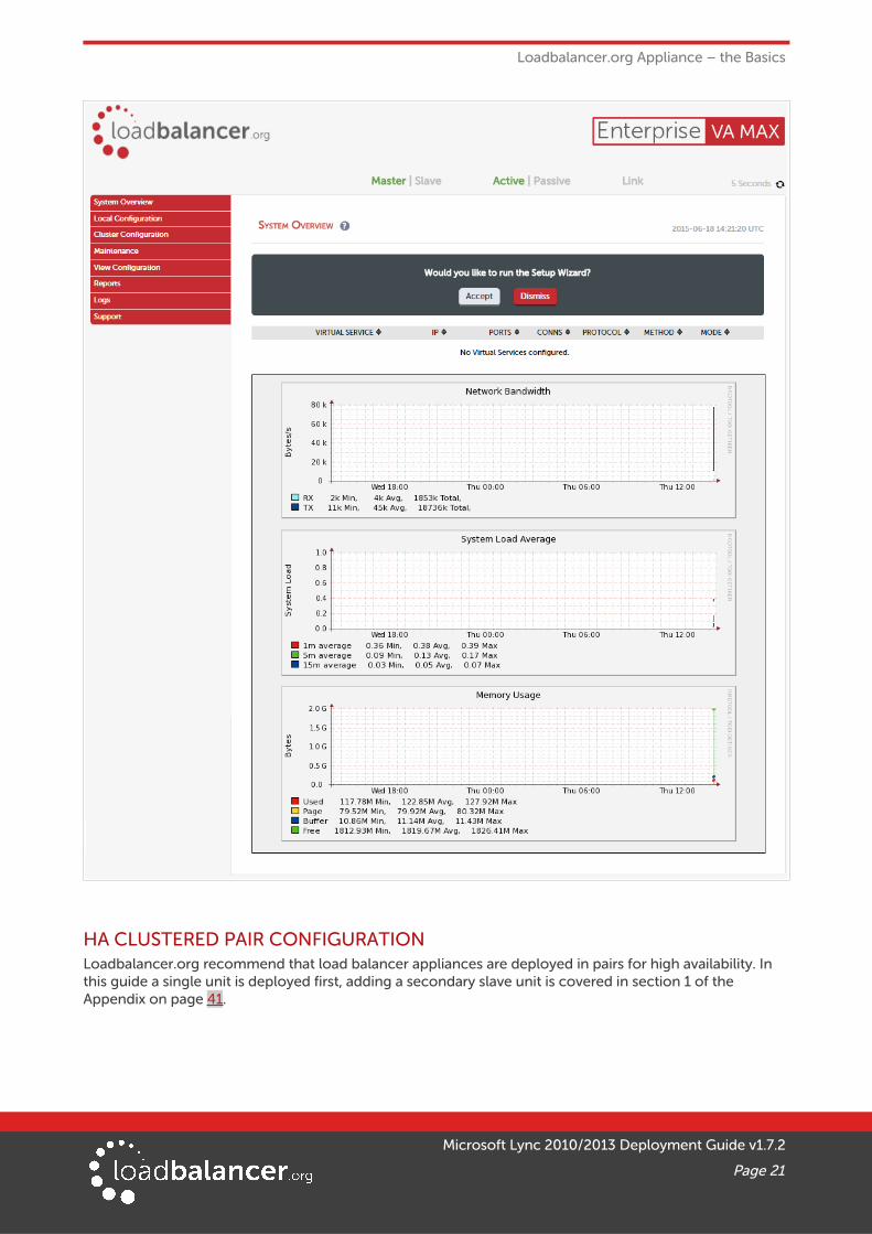
ACCESSING THE WEB USER INTERFACE (WEBUI)The WebUI can be accessed via HTTP at the following URL: http://192.168.2.21:9080/lbadmin
* Note the port number → 9080
The WebUI can be accessed via HTTPS at the following URL: https://192.168.2.21:9443/lbadmin
* Note the port number → 9443
(replace 192.168.2.21 with the IP address of your load balancer if it's been changed from the default)
Login using the following credentials:
Username: loadbalancer
Password: loadbalancer
Note:
To change the password , use the WebUI menu option: Maintenance > Passwords.
Once logged in, the WebUI will be displayed as shown on the following page:
Microsoft Lync 2010/2013 Deployment Guide v1.7.2
Page 20
Loadbalancer.org Appliance – the Basics
HA CLUSTERED PAIR CONFIGURATIONLoadbalancer.org recommend that load balancer appliances are deployed in pairs for high availability. In this guide a single unit is deployed first, adding a secondary slave unit is covered in section 1 of the Appendix on page 41.
Microsoft Lync 2010/2013 Deployment Guide v1.7.2
Page 21

Appliance Configuration for Lync
12. Appliance Configuration for Lync
STEP 1 – CONFIGURE LAYER 7 GLOBAL SETTINGSTo configure the TCP timeouts required by Lync, HAProxy's client and server timeouts must be changed from their default values of 43 seconds and 45 seconds respectively to 30 minutes. To do this follow the steps below:
1. Using the WebUI, navigate to: Configuration > Layer 7 – Advanced Configuration
2. Change Client Timeout to 1800000 as shown above (i.e. 1800000 ms which is 30 minutes)
Note: You can also enter 30m rather than 1800000
3. Change Real Server Timeout to 1800000 as shown above (i.e. 1800000 ms which is 30 minutes)
Note: You can also enter 30m rather than 1800000
4. Click the Update button to save the settings
STEP 2 – CONFIGURING THE LOAD BALANCED FRONT END SERVICES
VIRTUAL SERVICE (VIP) LISTThe table below shows VIPs that must be created:
VIP Name (Label) IP Address Port(s) Layer Layer 7 Protocol
Persistence Method
FrontEndPool 192.168.10.30 135, 443, 444, 5061, 5065, 5069
7 Other TCP Source IP address
FePoolExtWebSvcs8080 192.168.20.30 8080 7 Other TCP None or cookie *
FePoolExtWebSvcs4443 192.168.20.30 4443 7 Other TCP None or cookie *
* If only Lync 2013 front-end servers are used, no persistence is required. If 2010 front-end servers are used, then cookie persistence is required. Please refer to the relevant section below.
Microsoft Lync 2010/2013 Deployment Guide v1.7.2
Page 22
Appliance Configuration for Lync
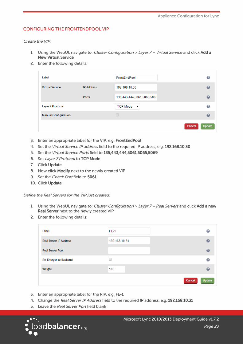
CONFIGURING THE FRONTENDPOOL VIP
Create the VIP:
1. Using the WebUI, navigate to: Cluster Configuration > Layer 7 – Virtual Service and click Add a New Virtual Service
2. Enter the following details:
3. Enter an appropriate label for the VIP, e.g. FrontEndPool
4. Set the Virtual Service IP address field to the required IP address, e.g. 192.168.10.30
5. Set the Virtual Service Ports field to 135,443,444,5061,5065,5069
6. Set Layer 7 Protocol to TCP Mode
7. Click Update
8. Now click Modify next to the newly created VIP
9. Set the Check Port field to 5061
10. Click Update
Define the Real Servers for the VIP just created:
1. Using the WebUI, navigate to: Cluster Configuration > Layer 7 – Real Servers and click Add a new Real Server next to the newly created VIP
2. Enter the following details:
3. Enter an appropriate label for the RIP, e.g. FE-1
4. Change the Real Server IP Address field to the required IP address, e.g. 192.168.10.31
5. Leave the Real Server Port field blank
Microsoft Lync 2010/2013 Deployment Guide v1.7.2
Page 23
Appliance Configuration for Lync
6. Click Update
7. Repeat the above steps to add your other Front End Server(s)
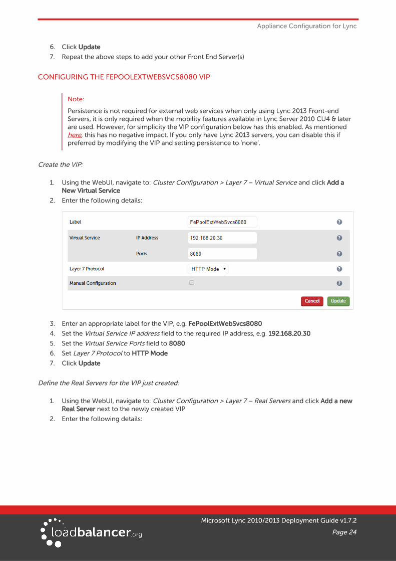
CONFIGURING THE FEPOOLEXTWEBSVCS8080 VIP
Note:
Persistence is not required for external web services when only using Lync 2013 Front-end Servers, it is only required when the mobility features available in Lync Server 2010 CU4 & later are used. However, for simplicity the VIP configuration below has this enabled. As mentioned here, this has no negative impact. If you only have Lync 2013 servers, you can disable this if preferred by modifying the VIP and setting persistence to 'none'.
Create the VIP:
1. Using the WebUI, navigate to: Cluster Configuration > Layer 7 – Virtual Service and click Add a New Virtual Service
2. Enter the following details:
3. Enter an appropriate label for the VIP, e.g. FePoolExtWebSvcs8080
4. Set the Virtual Service IP address field to the required IP address, e.g. 192.168.20.30
5. Set the Virtual Service Ports field to 8080
6. Set Layer 7 Protocol to HTTP Mode
7. Click Update
Define the Real Servers for the VIP just created:
1. Using the WebUI, navigate to: Cluster Configuration > Layer 7 – Real Servers and click Add a new Real Server next to the newly created VIP
2. Enter the following details:
Microsoft Lync 2010/2013 Deployment Guide v1.7.2
Page 24
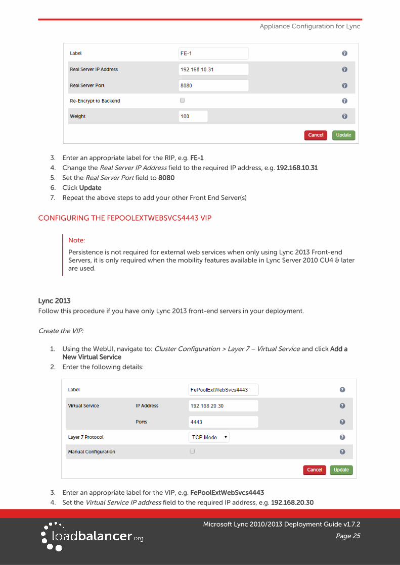
Appliance Configuration for Lync
3. Enter an appropriate label for the RIP, e.g. FE-1
4. Change the Real Server IP Address field to the required IP address, e.g. 192.168.10.31
5. Set the Real Server Port field to 8080
6. Click Update
7. Repeat the above steps to add your other Front End Server(s)
CONFIGURING THE FEPOOLEXTWEBSVCS4443 VIP
Note:
Persistence is not required for external web services when only using Lync 2013 Front-end Servers, it is only required when the mobility features available in Lync Server 2010 CU4 & later are used.
Lync 2013
Follow this procedure if you have only Lync 2013 front-end servers in your deployment.
Create the VIP:
1. Using the WebUI, navigate to: Cluster Configuration > Layer 7 – Virtual Service and click Add a New Virtual Service
2. Enter the following details:
3. Enter an appropriate label for the VIP, e.g. FePoolExtWebSvcs4443
4. Set the Virtual Service IP address field to the required IP address, e.g. 192.168.20.30
Microsoft Lync 2010/2013 Deployment Guide v1.7.2
Page 25
Appliance Configuration for Lync
5. Set the Virtual Service Ports field to 4443
6. Set Layer 7 Protocol to TCP Mode
7. Click Update
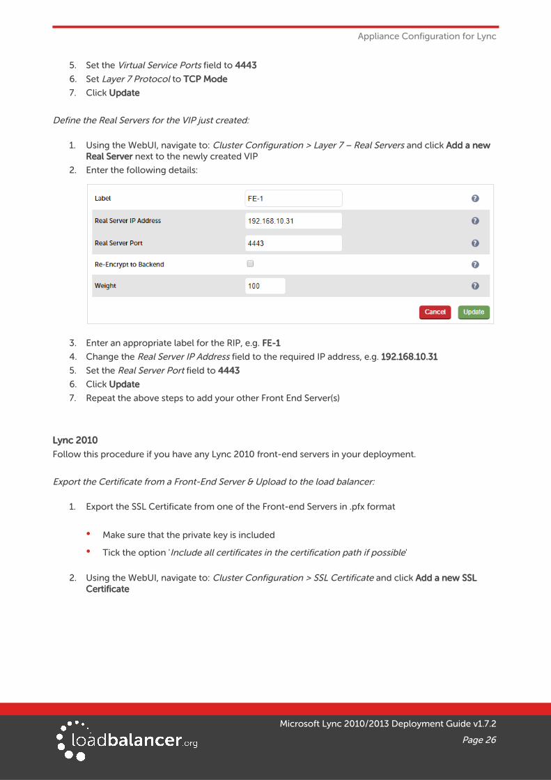
Define the Real Servers for the VIP just created:
1. Using the WebUI, navigate to: Cluster Configuration > Layer 7 – Real Servers and click Add a new Real Server next to the newly created VIP
2. Enter the following details:
3. Enter an appropriate label for the RIP, e.g. FE-1
4. Change the Real Server IP Address field to the required IP address, e.g. 192.168.10.31
5. Set the Real Server Port field to 4443
6. Click Update
7. Repeat the above steps to add your other Front End Server(s)
Lync 2010
Follow this procedure if you have any Lync 2010 front-end servers in your deployment.
Export the Certificate from a Front-End Server & Upload to the load balancer:
1. Export the SSL Certificate from one of the Front-end Servers in .pfx format
• Make sure that the private key is included
• Tick the option 'Include all certificates in the certification path if possible'
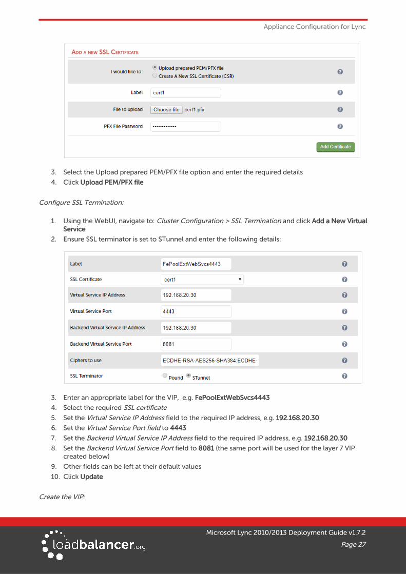
2. Using the WebUI, navigate to: Cluster Configuration > SSL Certificate and click Add a new SSL Certificate
Microsoft Lync 2010/2013 Deployment Guide v1.7.2
Page 26
Appliance Configuration for Lync
3. Select the Upload prepared PEM/PFX file option and enter the required details
4. Click Upload PEM/PFX file
Configure SSL Termination:
1. Using the WebUI, navigate to: Cluster Configuration > SSL Termination and click Add a New VirtualService
2. Ensure SSL terminator is set to STunnel and enter the following details:
3. Enter an appropriate label for the VIP, e.g. FePoolExtWebSvcs4443
4. Select the required SSL certificate
5. Set the Virtual Service IP Address field to the required IP address, e.g. 192.168.20.30
6. Set the Virtual Service Port field to 4443
7. Set the Backend Virtual Service IP Address field to the required IP address, e.g. 192.168.20.30
8. Set the Backend Virtual Service Port field to 8081 (the same port will be used for the layer 7 VIP created below)
9. Other fields can be left at their default values
10. Click Update
Create the VIP:
Microsoft Lync 2010/2013 Deployment Guide v1.7.2
Page 27
Appliance Configuration for Lync
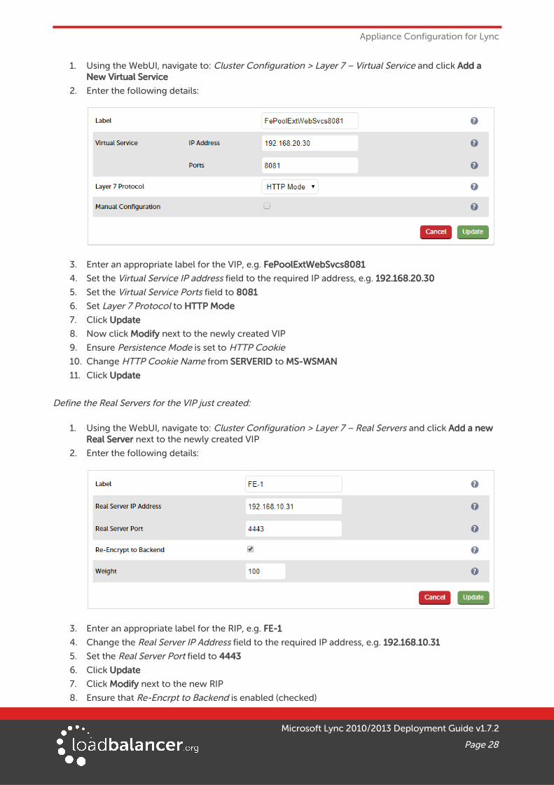
1. Using the WebUI, navigate to: Cluster Configuration > Layer 7 – Virtual Service and click Add a New Virtual Service
2. Enter the following details:
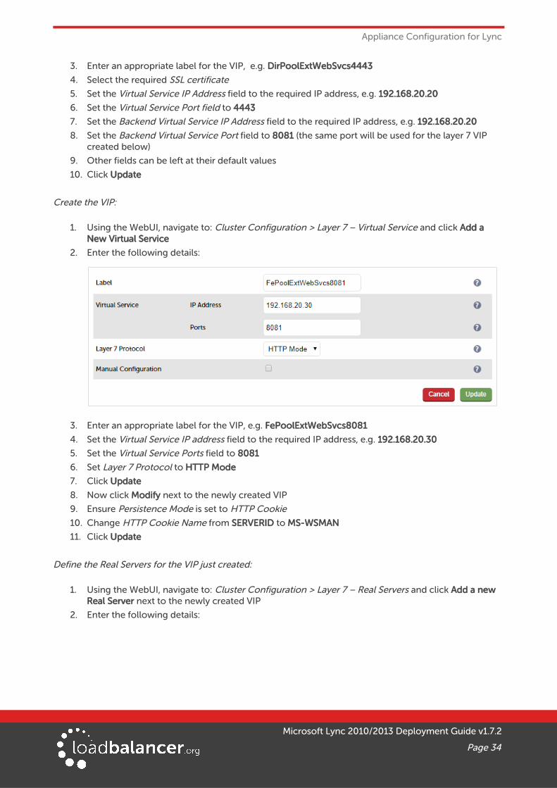
3. Enter an appropriate label for the VIP, e.g. FePoolExtWebSvcs8081
4. Set the Virtual Service IP address field to the required IP address, e.g. 192.168.20.30
5. Set the Virtual Service Ports field to 8081
6. Set Layer 7 Protocol to HTTP Mode
7. Click Update
8. Now click Modify next to the newly created VIP
9. Ensure Persistence Mode is set to HTTP Cookie
10. Change HTTP Cookie Name from SERVERID to MS-WSMAN
11. Click Update
Define the Real Servers for the VIP just created:
1. Using the WebUI, navigate to: Cluster Configuration > Layer 7 – Real Servers and click Add a new Real Server next to the newly created VIP
2. Enter the following details:
3. Enter an appropriate label for the RIP, e.g. FE-1
4. Change the Real Server IP Address field to the required IP address, e.g. 192.168.10.31
5. Set the Real Server Port field to 4443
6. Click Update
7. Click Modify next to the new RIP
8. Ensure that Re-Encrpt to Backend is enabled (checked)
Microsoft Lync 2010/2013 Deployment Guide v1.7.2
Page 28
Appliance Configuration for Lync
9. Click Update
10. Repeat the above steps to add your other Front End Server(s)
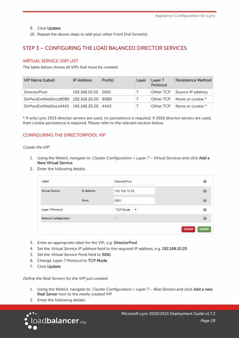
STEP 3 – CONFIGURING THE LOAD BALANCED DIRECTOR SERVICES
VIRTUAL SERVICE (VIP) LISTThe table below shows all VIPs that must be created:
VIP Name (Label) IP Address Port(s) Layer Layer 7 Protocol
Persistence Method
DirectorPool 192.168.10.20 5061 7 Other TCP Source IP address
DirPoolExtWebSvcs8080 192.168.20.20 8080 7 Other TCP None or cookie *
DirPoolExtWebSvcs4443 192.168.20.20 4443 7 Other TCP None or cookie *
* If only Lync 2013 director servers are used, no persistence is required. If 2010 director servers are used, then cookie persistence is required. Please refer to the relevant section below.
CONFIGURING THE DIRECTORPOOL VIP
Create the VIP:
1. Using the WebUI, navigate to: Cluster Configuration > Layer 7 – Virtual Services and click Add a New Virtual Service
2. Enter the following details:
3. Enter an appropriate label for the VIP, e.g. DirectorPool
4. Set the Virtual Service IP address field to the required IP address, e.g. 192.168.10.20
5. Set the Virtual Service Ports field to 5061
6. Change Layer 7 Protocol to TCP Mode
7. Click Update
Define the Real Servers for the VIP just created:
1. Using the WebUI, navigate to: Cluster Configuration > Layer 7 – Real Servers and click Add a new Real Server next to the newly created VIP
2. Enter the following details:
Microsoft Lync 2010/2013 Deployment Guide v1.7.2
Page 29
Appliance Configuration for Lync
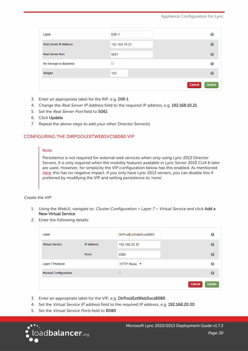
3. Enter an appropriate label for the RIP, e.g. DIR-1
4. Change the Real Server IP Address field to the required IP address, e.g. 192.168.10.21
5. Set the Real Server Port field to 5061
6. Click Update
7. Repeat the above steps to add your other Director Server(s)
CONFIGURING THE DIRPOOLEXTWEBSVCS8080 VIP
Note:
Persistence is not required for external web services when only using Lync 2013 Director Servers, it is only required when the mobility features available in Lync Server 2010 CU4 & later are used. However, for simplicity the VIP configuration below has this enabled. As mentioned here, this has no negative impact. If you only have Lync 2013 servers, you can disable this if preferred by modifying the VIP and setting persistence to 'none'.
Create the VIP:
1. Using the WebUI, navigate to: Cluster Configuration > Layer 7 – Virtual Service and click Add a New Virtual Service
2. Enter the following details:
3. Enter an appropriate label for the VIP, e.g. DirPoolExtWebSvcs8080
4. Set the Virtual Service IP address field to the required IP address, e.g. 192.168.20.30
5. Set the Virtual Service Ports field to 8080
Microsoft Lync 2010/2013 Deployment Guide v1.7.2
Page 30
Appliance Configuration for Lync
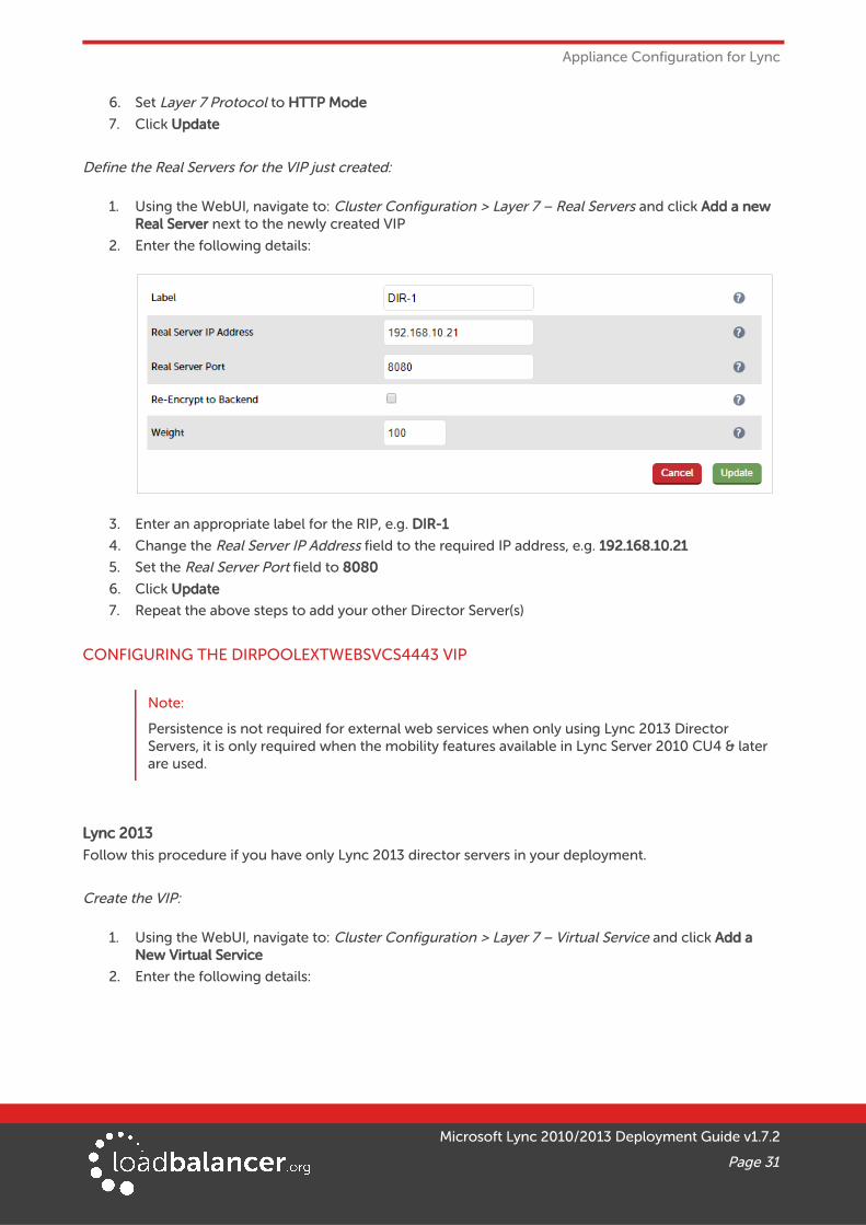
6. Set Layer 7 Protocol to HTTP Mode
7. Click Update
Define the Real Servers for the VIP just created:
1. Using the WebUI, navigate to: Cluster Configuration > Layer 7 – Real Servers and click Add a new Real Server next to the newly created VIP
2. Enter the following details:
3. Enter an appropriate label for the RIP, e.g. DIR-1
4. Change the Real Server IP Address field to the required IP address, e.g. 192.168.10.21
5. Set the Real Server Port field to 8080
6. Click Update
7. Repeat the above steps to add your other Director Server(s)
CONFIGURING THE DIRPOOLEXTWEBSVCS4443 VIP
Note:
Persistence is not required for external web services when only using Lync 2013 Director Servers, it is only required when the mobility features available in Lync Server 2010 CU4 & later are used.
Lync 2013
Follow this procedure if you have only Lync 2013 director servers in your deployment.
Create the VIP:
1. Using the WebUI, navigate to: Cluster Configuration > Layer 7 – Virtual Service and click Add a New Virtual Service
2. Enter the following details:
Microsoft Lync 2010/2013 Deployment Guide v1.7.2
Page 31
Appliance Configuration for Lync
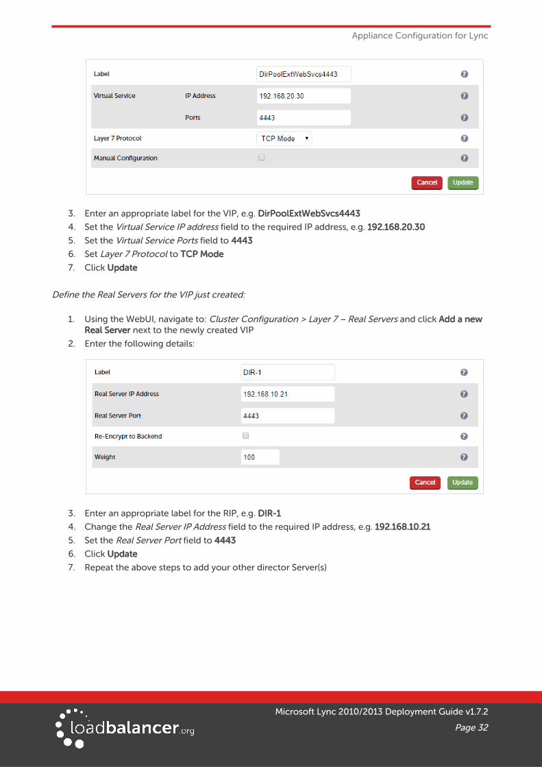
3. Enter an appropriate label for the VIP, e.g. DirPoolExtWebSvcs4443
4. Set the Virtual Service IP address field to the required IP address, e.g. 192.168.20.30
5. Set the Virtual Service Ports field to 4443
6. Set Layer 7 Protocol to TCP Mode
7. Click Update
Define the Real Servers for the VIP just created:
1. Using the WebUI, navigate to: Cluster Configuration > Layer 7 – Real Servers and click Add a new Real Server next to the newly created VIP
2. Enter the following details:
3. Enter an appropriate label for the RIP, e.g. DIR-1
4. Change the Real Server IP Address field to the required IP address, e.g. 192.168.10.21
5. Set the Real Server Port field to 4443
6. Click Update
7. Repeat the above steps to add your other director Server(s)
Microsoft Lync 2010/2013 Deployment Guide v1.7.2
Page 32
Appliance Configuration for Lync
Lync 2010
Follow this procedure if you have any Lync 2010 director servers in your deployment.
Export the Certificate from a Front-End Server & Upload to the load balancer:
1. Export the SSL Certificate from one of the Front-end Servers in .pfx format
• Make sure that the private key is included
• Tick the option 'Include all certificates in the certification path if possible'
2. Using the WebUI, navigate to: Cluster Configuration > SSL Certificate and click Add a new SSL Certificate
3. Select the Upload prepared PEM/PFX file option and enter the required details
4. Click Upload PEM/PFX file
Configure SSL Termination:
1. Using the WebUI, navigate to: Cluster Configuration > SSL Termination and click Add a New VirtualService
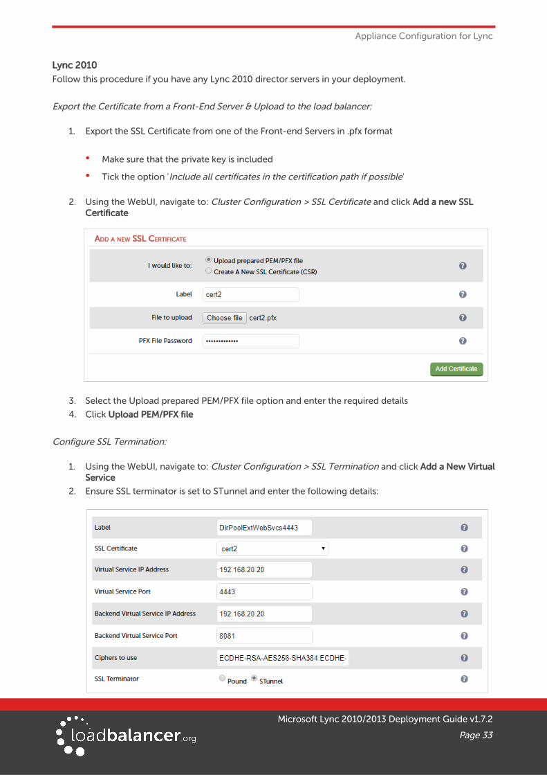
2. Ensure SSL terminator is set to STunnel and enter the following details:
Microsoft Lync 2010/2013 Deployment Guide v1.7.2
Page 33
Appliance Configuration for Lync
3. Enter an appropriate label for the VIP, e.g. DirPoolExtWebSvcs4443
4. Select the required SSL certificate
5. Set the Virtual Service IP Address field to the required IP address, e.g. 192.168.20.20
6. Set the Virtual Service Port field to 4443
7. Set the Backend Virtual Service IP Address field to the required IP address, e.g. 192.168.20.20
8. Set the Backend Virtual Service Port field to 8081 (the same port will be used for the layer 7 VIP created below)
9. Other fields can be left at their default values
10. Click Update
Create the VIP:
1. Using the WebUI, navigate to: Cluster Configuration > Layer 7 – Virtual Service and click Add a New Virtual Service
2. Enter the following details:
3. Enter an appropriate label for the VIP, e.g. FePoolExtWebSvcs8081
4. Set the Virtual Service IP address field to the required IP address, e.g. 192.168.20.30
5. Set the Virtual Service Ports field to 8081
6. Set Layer 7 Protocol to HTTP Mode
7. Click Update
8. Now click Modify next to the newly created VIP
9. Ensure Persistence Mode is set to HTTP Cookie
10. Change HTTP Cookie Name from SERVERID to MS-WSMAN
11. Click Update
Define the Real Servers for the VIP just created:
1. Using the WebUI, navigate to: Cluster Configuration > Layer 7 – Real Servers and click Add a new Real Server next to the newly created VIP
2. Enter the following details:
Microsoft Lync 2010/2013 Deployment Guide v1.7.2
Page 34
Appliance Configuration for Lync
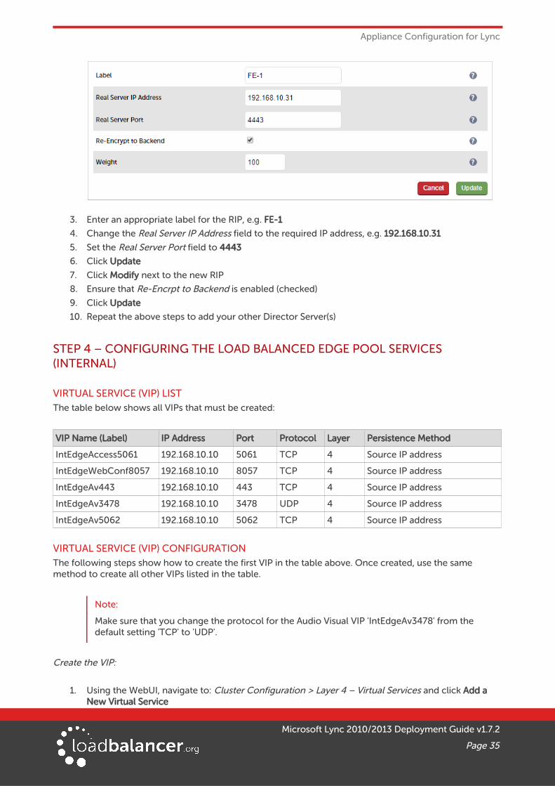
3. Enter an appropriate label for the RIP, e.g. FE-1
4. Change the Real Server IP Address field to the required IP address, e.g. 192.168.10.31
5. Set the Real Server Port field to 4443
6. Click Update
7. Click Modify next to the new RIP
8. Ensure that Re-Encrpt to Backend is enabled (checked)
9. Click Update
10. Repeat the above steps to add your other Director Server(s)
STEP 4 – CONFIGURING THE LOAD BALANCED EDGE POOL SERVICES (INTERNAL)
VIRTUAL SERVICE (VIP) LISTThe table below shows all VIPs that must be created:
VIP Name (Label) IP Address Port Protocol Layer Persistence Method
IntEdgeAccess5061 192.168.10.10 5061 TCP 4 Source IP address
IntEdgeWebConf8057 192.168.10.10 8057 TCP 4 Source IP address
IntEdgeAv443 192.168.10.10 443 TCP 4 Source IP address
IntEdgeAv3478 192.168.10.10 3478 UDP 4 Source IP address
IntEdgeAv5062 192.168.10.10 5062 TCP 4 Source IP address
VIRTUAL SERVICE (VIP) CONFIGURATIONThe following steps show how to create the first VIP in the table above. Once created, use the same method to create all other VIPs listed in the table.
Note:
Make sure that you change the protocol for the Audio Visual VIP 'IntEdgeAv3478' from the default setting 'TCP' to 'UDP'.
Create the VIP:
1. Using the WebUI, navigate to: Cluster Configuration > Layer 4 – Virtual Services and click Add a New Virtual Service
Microsoft Lync 2010/2013 Deployment Guide v1.7.2
Page 35
Appliance Configuration for Lync
2. Enter the following details:
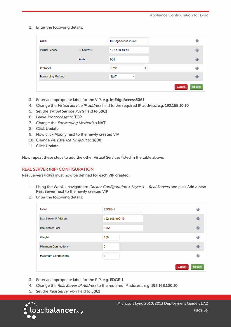
3. Enter an appropriate label for the VIP, e.g. IntEdgeAccess5061
4. Change the Virtual Service IP address field to the required IP address, e.g. 192.168.10.10
5. Set the Virtual Service Ports field to 5061
6. Leave Protocol set to TCP
7. Change the Forwarding Method to NAT
8. Click Update
9. Now click Modify next to the newly created VIP
10. Change Persistence Timeout to 1800
11. Click Update
Now repeat these steps to add the other Virtual Services listed in the table above.
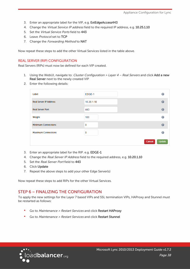
REAL SERVER (RIP) CONFIGURATIONReal Servers (RIPs) must now be defined for each VIP created.
1. Using the WebUI, navigate to: Cluster Configuration > Layer 4 – Real Servers and click Add a new Real Server next to the newly created VIP
2. Enter the following details:
3. Enter an appropriate label for the RIP, e.g. EDGE-1
4. Change the Real Server IP Address to the required IP address, e.g. 192.168.100.10
5. Set the Real Server Port field to 5061
Microsoft Lync 2010/2013 Deployment Guide v1.7.2
Page 36
Appliance Configuration for Lync
6. Click Update
7. Repeat the above steps to add your other Edge Server(s)
Now repeat these steps to add RIPs for the other Virtual Services.
STEP 5 – CONFIGURING THE LOAD BALANCED EDGE POOL SERVICES (EXTERNAL)
VIRTUAL SERVICE (VIP) LISTThe table below shows all VIPs that must be created:
VIP Name (Label) IP Address Port Protocol Layer Persistence Method
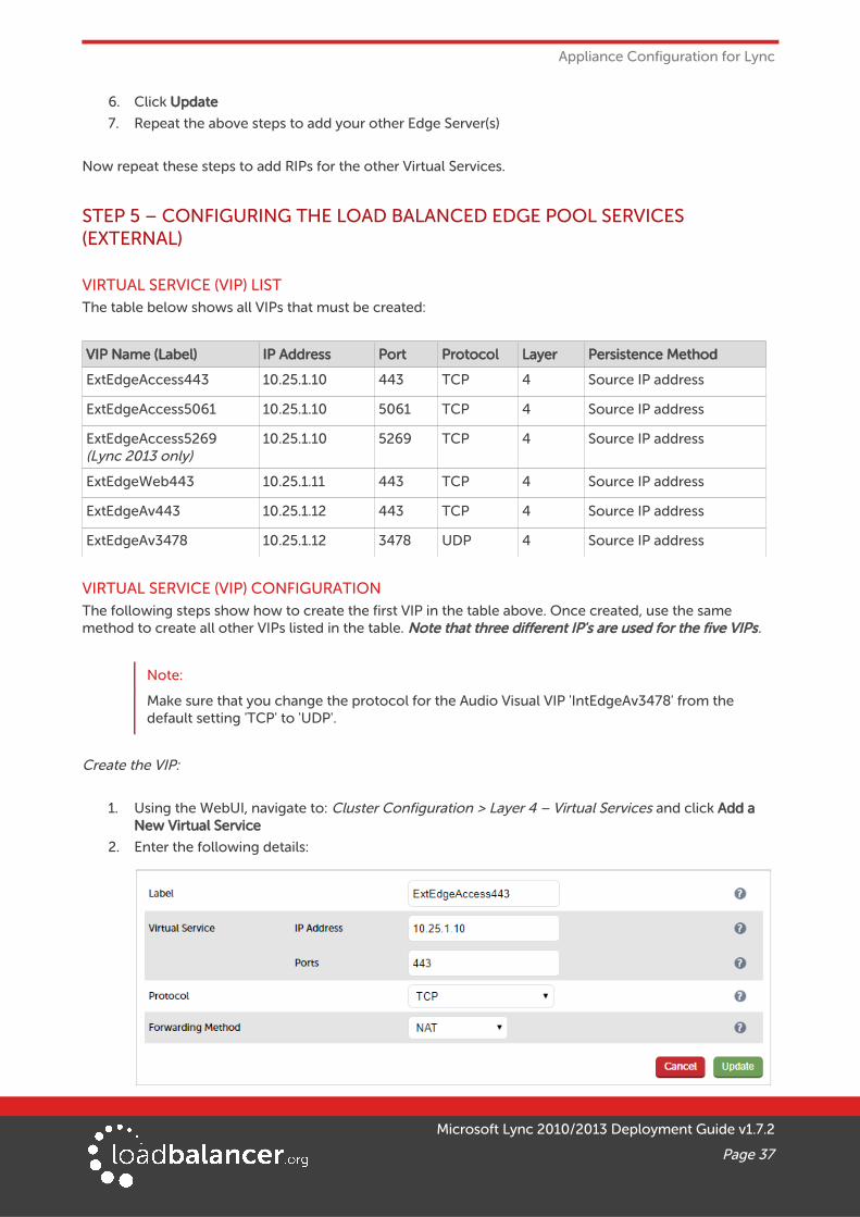
ExtEdgeAccess443 10.25.1.10 443 TCP 4 Source IP address
ExtEdgeAccess5061 10.25.1.10 5061 TCP 4 Source IP address
ExtEdgeAccess5269(Lync 2013 only)
10.25.1.10 5269 TCP 4 Source IP address
ExtEdgeWeb443 10.25.1.11 443 TCP 4 Source IP address
ExtEdgeAv443 10.25.1.12 443 TCP 4 Source IP address
ExtEdgeAv3478 10.25.1.12 3478 UDP 4 Source IP address
VIRTUAL SERVICE (VIP) CONFIGURATIONThe following steps show how to create the first VIP in the table above. Once created, use the same method to create all other VIPs listed in the table. Note that three different IP's are used for the five VIPs.
Note:
Make sure that you change the protocol for the Audio Visual VIP 'IntEdgeAv3478' from the default setting 'TCP' to 'UDP'.
Create the VIP:
1. Using the WebUI, navigate to: Cluster Configuration > Layer 4 – Virtual Services and click Add a New Virtual Service
2. Enter the following details:
Microsoft Lync 2010/2013 Deployment Guide v1.7.2
Page 37
Appliance Configuration for Lync
3. Enter an appropriate label for the VIP, e.g. ExtEdgeAccess443
4. Change the Virtual Service IP address field to the required IP address, e.g. 10.25.1.10
5. Set the Virtual Service Ports field to 443
6. Leave Protocol set to TCP
7. Change the Forwarding Method to NAT
Now repeat these steps to add the other Virtual Services listed in the table above.
REAL SERVER (RIP) CONFIGURATIONReal Servers (RIPs) must now be defined for each VIP created.
1. Using the WebUI, navigate to: Cluster Configuration > Layer 4 – Real Servers and click Add a new Real Server next to the newly created VIP
2. Enter the following details:
3. Enter an appropriate label for the RIP. e.g. EDGE-1
4. Change the Real Server IP Address field to the required address, e.g. 10.20.1.10
5. Set the Real Server Port field to 443
6. Click Update
7. Repeat the above steps to add your other Edge Server(s)
Now repeat these steps to add RIPs for the other Virtual Services.
STEP 6 – FINALIZING THE CONFIGURATIONTo apply the new settings for the Layer 7 based VIPs and SSL termination VIPs, HAProxy and Stunnel must be restarted as follows:
• Go to Maintenance > Restart Services and click Restart HAProxy
• Go to Maintenance > Restart Services and click Restart Stunnel
Microsoft Lync 2010/2013 Deployment Guide v1.7.2
Page 38
Testing & Validation
13. Testing & Validation
CLIENT CONNECTIONS BYPASS THE LOAD BALANCERIt's important to note that client connections can bypass the load balancer and connect directly to one of the Front End servers (this will be the users home server if available). This is normal and expected behavior and is explained in the 'Client Registration' section of the following technet article:
http://blogs.technet.com/b/nexthop/archive/2011/05/25/dns-load-balancing-in-lync-server-2010.aspx
TAKING SERVERS OFFLINEAs explained in the section above, client connections can be direct to one of the Front End servers. In this case, taking a server offline using only the load balancer will have no effect. Therefore, a two step approach is suggested:
• Drain the server using the Lync Control Panel – this will cause all clients to reconnect to one of the other Front-End servers. Note that active calls and conferencing session should remain active until closed
• Take the server offline (Drain) using System Overview in the load balancer's WebUI – this will ensure that existing connections can continue until closed, new connections that pass via the loadbalancer will be directed to a different Front End server
MICROSOFT LYNC TESTING TOOLThe Microsoft Lync/OCS Server Remote Connectivity Analyzer tool is a very useful Web-based Microsoft tool designed to help IT Administrators troubleshoot their Lync deployments. It's available at the followinglink: https://testconnectivity.microsoft.com/
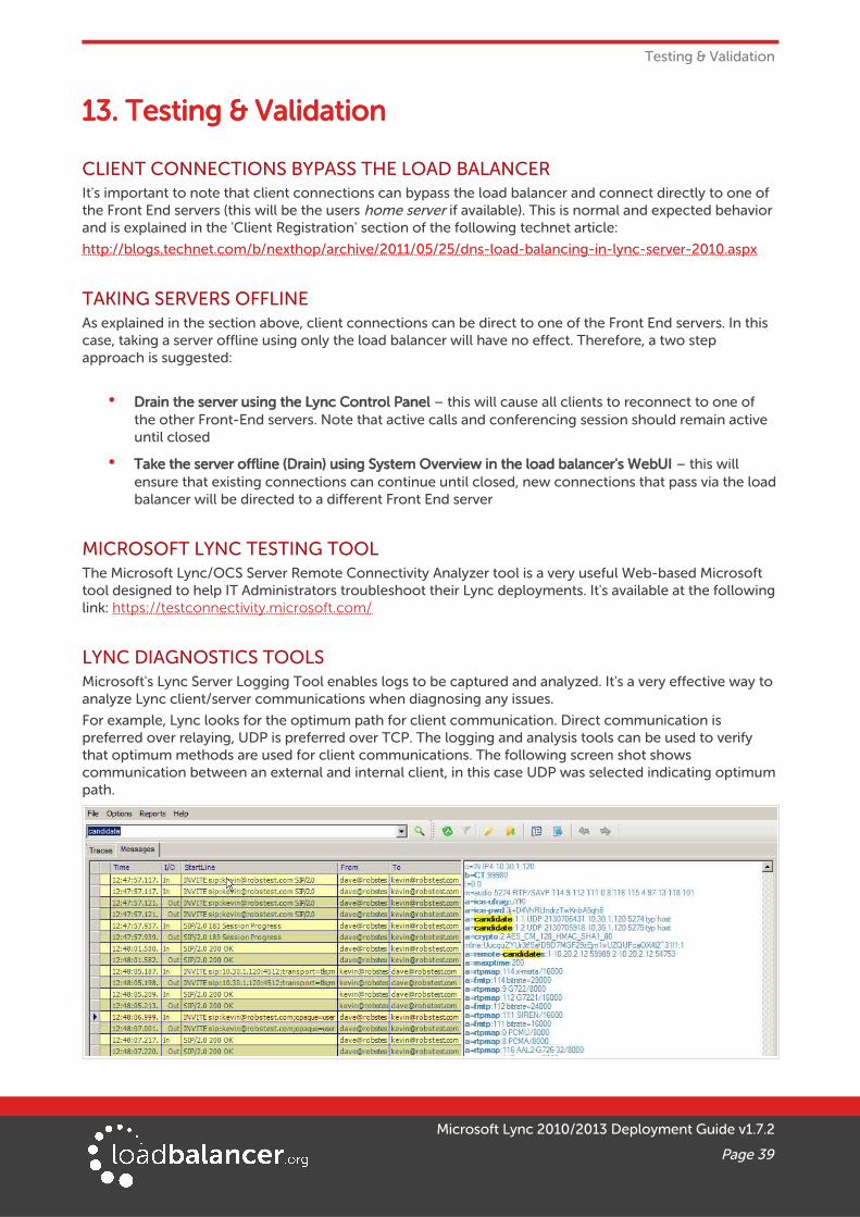
LYNC DIAGNOSTICS TOOLSMicrosoft's Lync Server Logging Tool enables logs to be captured and analyzed. It's a very effective way to analyze Lync client/server communications when diagnosing any issues.
For example, Lync looks for the optimum path for client communication. Direct communication is preferred over relaying, UDP is preferred over TCP. The logging and analysis tools can be used to verify that optimum methods are used for client communications. The following screen shot shows communication between an external and internal client, in this case UDP was selected indicating optimumpath.
Microsoft Lync 2010/2013 Deployment Guide v1.7.2
Page 39
Testing & Validation
For additional guidelines on using the logging tool refer to the following link:
http://msdn.microsoft.com/en-us/library/lync/hh347311.aspx
Note:
To be able to analyze the logs, download and install the Microsoft Lync Server Resource Kit Tools from the following link:
2010: http://www.microsoft.com/en-us/download/details.aspx?id=21165
2013: http://www.microsoft.com/en-us/download/details.aspx?id=36821
WIRESHARK PROTOCOL ANALYZERWireshark is an excellent tool that can be used to analyze network traffic when diagnosing any network related issues. Wireshark is available for download at the following link:
http://www.wireshark.org/download.html
OTHER USEFUL RESOURCES
Microsoft Lync Server Documentation Hub
http://blogs.technet.com/b/nexthop/
Testing & verifying Lync Edge Server:
http://blogs.technet.com/b/nexthop/archive/2011/12/07/useful-tips-for-testing-your-lync-edge-server.aspx
Reverse Proxy Concepts & Testing Web Services:
http://social.technet.microsoft.com/wiki/contents/articles/9807.configuring-forefront-tmg-2010-as-reverse-proxy-for-lync-server-2010.aspx
Using ISS ARR as a Reverse Proxy for Lync:
http://blogs.technet.com/b/nexthop/archive/2013/02/19/using-iis-arr-as-a-reverse-proxy-for-lync-server-2013.aspx
14. Technical SupportIf you have any questions regarding the appliance or would like assistance designing your deployment, please don't hesitate to contact our support team: [email protected].
15. Further DocumentationThe Administration Manual contains much more information about configuring and deploying the appliance. It's available here: http://pdfs.loadbalancer.org/loadbalanceradministrationv8.pdf
16. ConclusionLoadbalancer.org appliances provide a very cost effective solution for highly available load balanced Microsoft Lync Server environments.
Microsoft Lync 2010/2013 Deployment Guide v1.7.2
Page 40
Appendix
17. Appendix1 – CLUSTERED PAIR CONFIGURATION – ADDING A SLAVE UNITIf you initially configured just the master unit and now need to add a slave - our recommended procedure,please refer to the relevant section below for more details:
Note:
A number of settings are not replicated as part of the master/slave pairing process and thereforemust be manually configured on the slave appliance. These are listed below:
• Hostname & DNS settings
• Network settings including IP addresses, bonding configuration and VLANs
• Routing configuration including default gateways and static routes
• Date & time settings
• Physical – Advanced Configuration settings including Internet Proxy IP address & port, Firewall table size, SMTP relay and Syslog server
• SNMP settings
• Graphing settings
• Firewall Script & Firewall Lockdown Script settings
• Software updates
Version 7:
Please refer to Chapter 8 – Appliance Clustering for HA in the v7 Administration Manual.
Version 8:
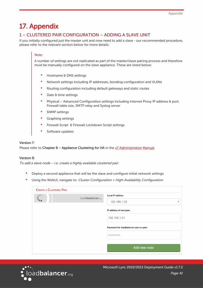
To add a slave node – i.e. create a highly available clustered pair:
• Deploy a second appliance that will be the slave and configure initial network settings
• Using the WebUI, navigate to: Cluster Configuration > High-Availability Configuration
Microsoft Lync 2010/2013 Deployment Guide v1.7.2
Page 41
Appendix
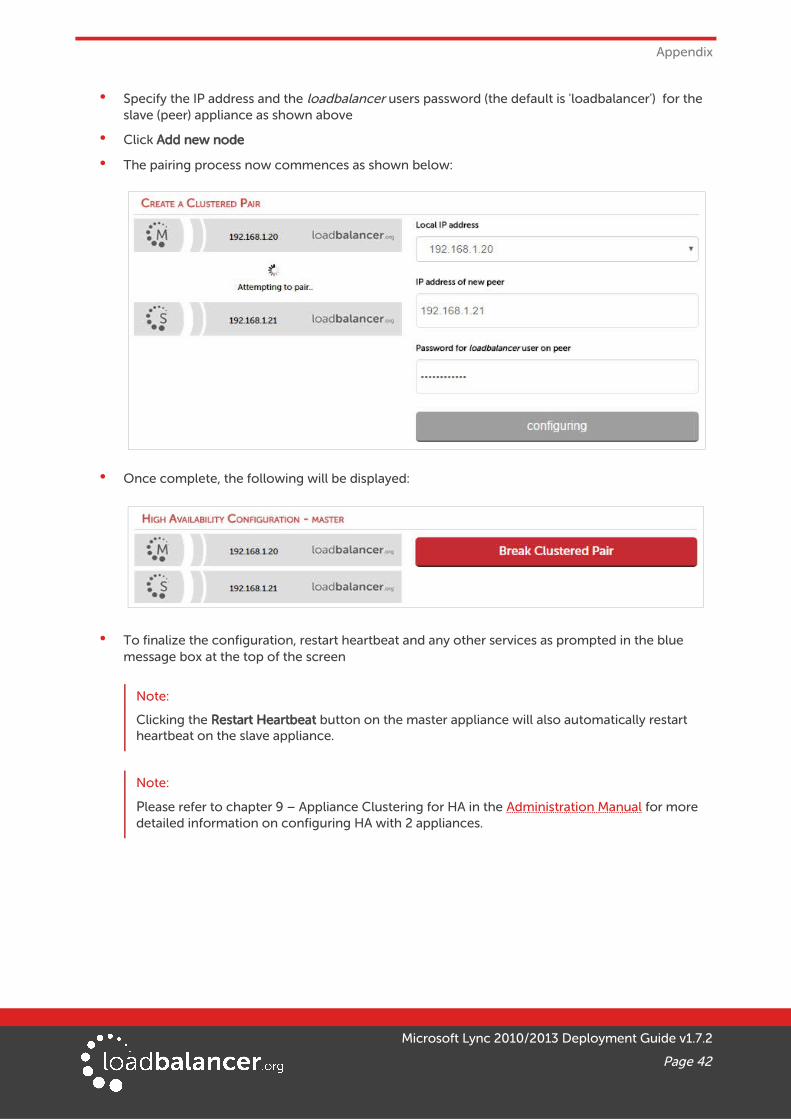
• Specify the IP address and the loadbalancer users password (the default is 'loadbalancer') for the slave (peer) appliance as shown above
• Click Add new node
• The pairing process now commences as shown below:
• Once complete, the following will be displayed:
• To finalize the configuration, restart heartbeat and any other services as prompted in the blue message box at the top of the screen
Note:
Clicking the Restart Heartbeat button on the master appliance will also automatically restart heartbeat on the slave appliance.
Note:
Please refer to chapter 9 – Appliance Clustering for HA in the Administration Manual for more detailed information on configuring HA with 2 appliances.
Microsoft Lync 2010/2013 Deployment Guide v1.7.2
Page 42
Appendix
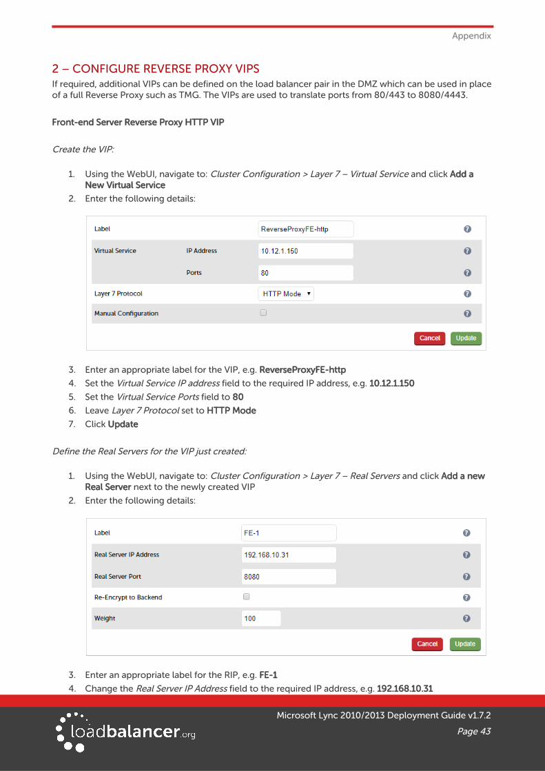
2 – CONFIGURE REVERSE PROXY VIPSIf required, additional VIPs can be defined on the load balancer pair in the DMZ which can be used in placeof a full Reverse Proxy such as TMG. The VIPs are used to translate ports from 80/443 to 8080/4443.
Front-end Server Reverse Proxy HTTP VIP
Create the VIP:
1. Using the WebUI, navigate to: Cluster Configuration > Layer 7 – Virtual Service and click Add a New Virtual Service
2. Enter the following details:
3. Enter an appropriate label for the VIP, e.g. ReverseProxyFE-http
4. Set the Virtual Service IP address field to the required IP address, e.g. 10.12.1.150
5. Set the Virtual Service Ports field to 80
6. Leave Layer 7 Protocol set to HTTP Mode
7. Click Update
Define the Real Servers for the VIP just created:
1. Using the WebUI, navigate to: Cluster Configuration > Layer 7 – Real Servers and click Add a new Real Server next to the newly created VIP
2. Enter the following details:
3. Enter an appropriate label for the RIP, e.g. FE-1
4. Change the Real Server IP Address field to the required IP address, e.g. 192.168.10.31
Microsoft Lync 2010/2013 Deployment Guide v1.7.2
Page 43
Appendix
5. Set the Real Server Port field to 8080
6. Click Update
7. Repeat the above steps to add your other Front End Server(s)
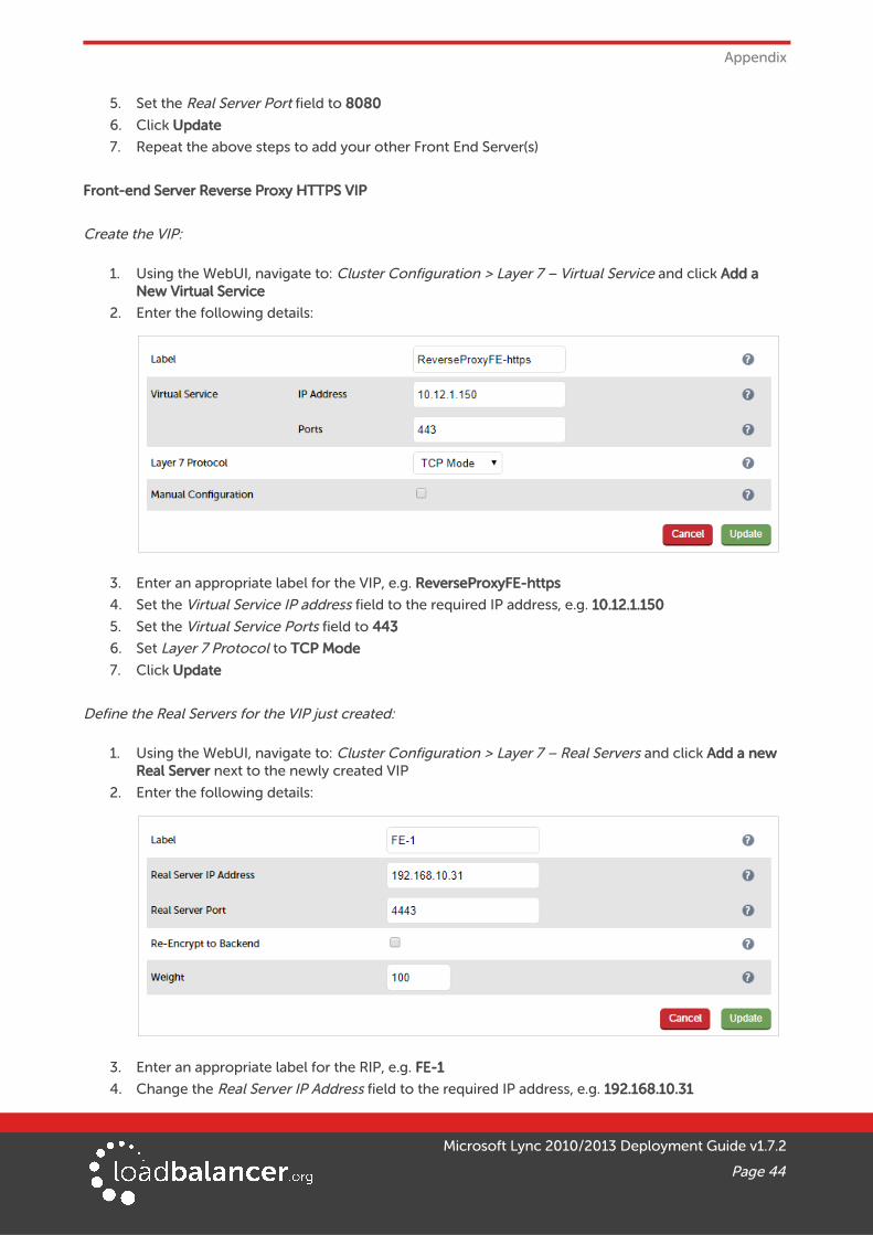
Front-end Server Reverse Proxy HTTPS VIP
Create the VIP:
1. Using the WebUI, navigate to: Cluster Configuration > Layer 7 – Virtual Service and click Add a New Virtual Service
2. Enter the following details:
3. Enter an appropriate label for the VIP, e.g. ReverseProxyFE-https
4. Set the Virtual Service IP address field to the required IP address, e.g. 10.12.1.150
5. Set the Virtual Service Ports field to 443
6. Set Layer 7 Protocol to TCP Mode
7. Click Update
Define the Real Servers for the VIP just created:
1. Using the WebUI, navigate to: Cluster Configuration > Layer 7 – Real Servers and click Add a new Real Server next to the newly created VIP
2. Enter the following details:
3. Enter an appropriate label for the RIP, e.g. FE-1
4. Change the Real Server IP Address field to the required IP address, e.g. 192.168.10.31
Microsoft Lync 2010/2013 Deployment Guide v1.7.2
Page 44

Appendix
5. Set the Real Server Port field to 4443
6. Click Update
7. Repeat the above steps to add your other Front End Server(s)
Director Server Reverse Proxy HTTP & HTTPS VIPs
Repeat the steps above to create similar VIPs/RIPs for the Director Server Web Services.
Microsoft Lync 2010/2013 Deployment Guide v1.7.2
Page 45
Appendix
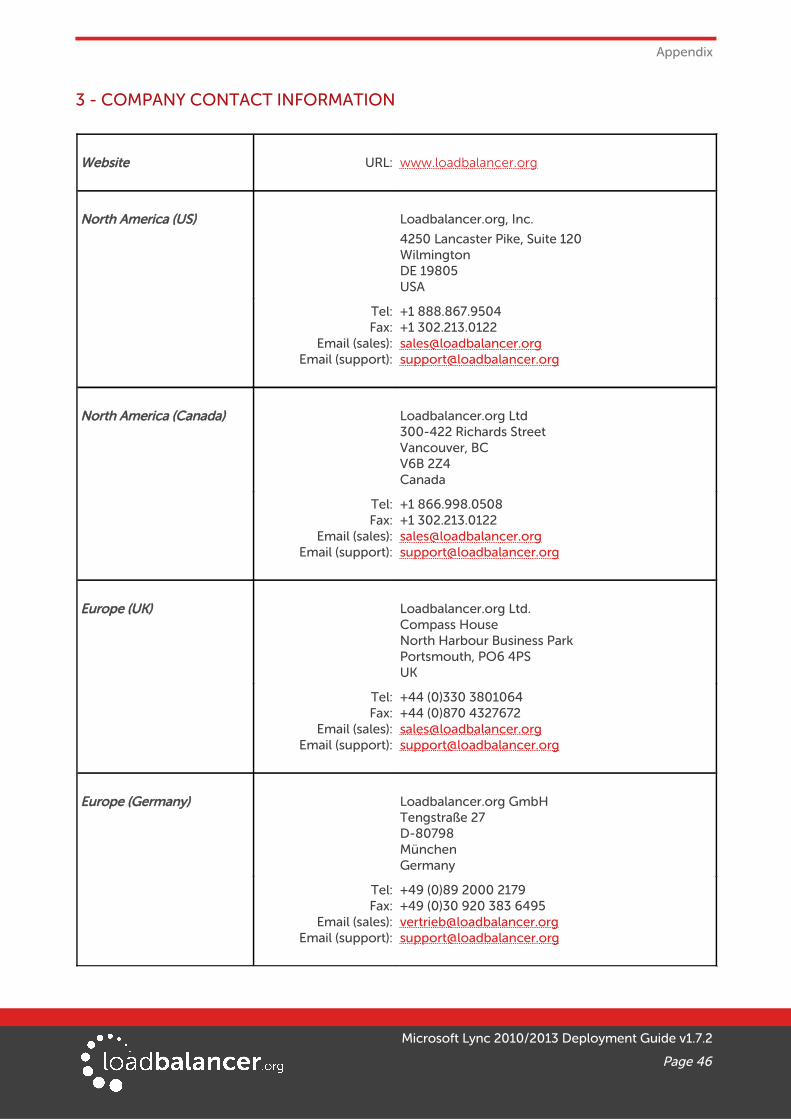
3 - COMPANY CONTACT INFORMATION
Website URL: w w w.loadbalancer.org
North America (US) Loadbalancer.org, Inc.
4250 Lancaster Pike, Suite 120WilmingtonDE 19805USA
Tel:Fax:
Email (sales):Email (support):
+1 888.867.9504+1 [email protected]@loadbalancer.org
North America (Canada) Loadbalancer.org Ltd300-422 Richards StreetVancouver, BCV6B 2Z4Canada
Tel:Fax:
Email (sales):Email (support):
+1 866.998.0508+1 [email protected]@loadbalancer.org
Europe (UK) Loadbalancer.org Ltd.Compass HouseNorth Harbour Business ParkPortsmouth, PO6 4PSUK
Tel:Fax:
Email (sales):Email (support):
+44 (0)330 3801064+44 (0)870 [email protected]@loadbalancer.org
Europe (Germany) Loadbalancer.org GmbHTengstraße 27D-80798MünchenGermany
Tel:Fax:
Email (sales):Email (support):
+49 (0)89 2000 2179+49 (0)30 920 383 [email protected]@loadbalancer.org
Microsoft Lync 2010/2013 Deployment Guide v1.7.2
Page 46


