AIR EPA United States Office of Air Quality Environmental Protection Planning And Standards March 1984 Agency Research Triangle Park, NC 27711 EPA-450/4-84-007a LOCATING AND ESTIMATING AIR EMISSIONS FROM SOURCES OF ACRYLONITRILE L &E
Transcript
AIR
EPA
United States Office of Air Quality
Environmental Protection Planning And StandardsMarch 1984Agency Research Triangle Park, NC 27711
EPA-450/4-84-007a
LOCATING AND ESTIMATING AIREMISSIONS FROM SOURCES OFACRYLONITRILE
L & E
EPA-450/4-84-007aMarch 1984
LOCATING AND ESTIMATING AIR EMISSIONS FROMSOURCES OF ACRYLONITRILE
U.S. ENVIRONMENTAL PROTECTION AGENCYOffice of Air and Radiation
Office of Air Quality Planning and StandardsResearch Triangle Park, North Carolina 27711
ii
This report has been reviewed by the Office Of Air Quality Planning And Standards, U.S. EnvironmentalProtection Agency, and has been approved for publication as received from GCA Technology. Approval doesnot signify that the contents necessarily reflect the views and policies of the Agency, neither does mention oftrade names or commercial products constitute endorsement or recommendation for use.
11 Advantages and Disadvantages of Acrylonitrile Sampling and Analysis Procedures . . . . . . . . . . 58
1
ACRYLONITRILE
SECTION 1
PURPOSE OF DOCUMENT
EPA, States, and local air pollution control agencies are
becoming increasingly aware of the presence of substances in the
ambient air that may be toxic at certain concentrations. This
awareness, in turn, has led to attempts to identify
source/receptor relationships for these substances and to develop
control programs to regulate emissions. Unfortunately, very
little information is available on the ambient air concentrations
of these substances or on the sources that may be discharging them
to the atmosphere.
To assist groups interested in inventorying air emissions of
various potentially toxic substances, EPA is preparing a series of
documents such as this that compiles available information on
sources and emissions of these substances. This document
specifically deals with acrylonitrile. Its intended audience
includes Federal, State, and local air pollution personnel and
others who are interested in locating potential emitters of
acrylonitrile and making gross estimates of air emissions
therefrom.
Because of the limited amounts of data available on
acrylonitrile emissions, and since the configuration of many
sources will not be the same as those described herein, this
document is best used as a primer to inform air pollution
personnel about (1) the types of sources that may emit
acrylonitrile, (2) process variations and release points that may
be expected within these sources, and (3) available emissions
information indicating the potential for acrylonitrile to be
released into the air from each operation.
2
The reader is strongly cautioned against using the emissions
information contained in this document to try to develop an exact
assessment of emissions from any particular facility. Since
insufficient data are available to develop statistical estimates
of the accuracy of these emission factors, no estimate can be made
of the error that could result when these factors are used to
calculate emissions for any given facility. It is possible, in
some extreme cases, that orders-of-magnitude differences could
result between actual and calculated emissions, depending on
differences in source configurations, control equipment and
operating practices. Thus, in situations where an accurate
assessment of acrylonitrile emissions is necessary,
source-specific information should be obtained to confirm the
existence of particular emitting operations, the types and
effectiveness of control measures, and the impact of operating
practices. A source test and/or material balance should be
considered as the best means to determine air emissions directly
from an operation.
3
SECTION 2
OVERVIEW OF DOCUMENT CONTENTS
As noted in Section 1, the purpose of this document is to
assist Federal, State, and local air pollution agencies and others
who are interested in locating potential air emitters of
acrylonitrile and making gross estimates of air emissions
therefrom. Because of the limited background data available, the
information summarized in this document does not and should not be
assumed to represent the source configuration or emissions
associated with any particular facility.
This section provides an overview of the contents of this
document. It briefly outlines the nature, extent and format of
the material presented in the remaining sections of this report.
Section 3 of this document provides a brief summary of the
physical and chemical characteristics of acrylonitrile, its
commonly occurring forms and an overview of its production and
uses. A table summarizes the quantities of acrylonitrile consumed
in various end uses in the United States. This background section
may be useful to someone who needs to develop a general
perspective on the nature of the substance and where it is
manufactured and consumed.
The fourth and fifth sections of this document focus on major
industrial source categories that may discharge acrylonitrile air
emissions. Section 4 discusses the production of acrylonitrile and
Section 5 discusses the use of acrylonitrile as an industrial
feedstock in the production of acrylic fibers, SAN/ABS resins,
nitrile elastomers, acrylamide, and adiponitrile. For each major
industrial source category described in Section 4 and Section 5,
4
example process descriptions and flow diagrams are given,
potential emission points are identified, and available emission
factor estimates are presented that show the potential for
acrylonitrile emissions before and after controls employed by
industry. Individual companies are named that are reported to be
involved with either the production and/or use of acrylonitrile,
based on industry contacts and available trade publications.
The final section of this document (Section 6) summarizes
available procedures for source sampling and analysis of
acrylonitrile. Details are not prescribed nor is any EPA
endorsement given or implied to any of these sampling and analysis
procedures. At this time, EPA has generally not evaluated these
methods. Consequently, this document merely provides an overview
of applicable source sampling procedures, citing references for
those interested in conducting source tests.
This document does not contain any discussion of health or
other environmental effects of acrylonitrile, nor does it include
any discussion of ambient air levels or ambient air monitoring
techniques.
Comments on the contents or usefulness of this document are
welcomed, as is any information on process descriptions, operating
practices, control measures and emissions information that would
enable EPA to improve its contents. All comments should be sent
to:
Chief, Source Analysis Section (MD-14)Air Management Technology BranchU. S. Environmental Protection AgencyResearch Triangle Park, N. C. 27711
5
SECTION 3
BACKGROUND
NATURE OF POLLUTANT
Acrylonitrile is a colorless liquid at normal temperatures
and pressure and has a faint characteristic odor. The chemical
formula for acrylonitrile is CH2=CH-C=N. Acrylonitrile has
several synonyms and tradenames including propenenitrile, vinyl
cyanide, cyanoethylene, Acrylon®, Carbacryl®, Fumigrain®, and
Ventox®. Selected physical and chemical properties of
acrylonitrile are presented in Table 1.1
Acrylonitrile is relatively volatile with a vapor pressure of
13.3 kPa (1.9 psi) at 25°C (77°F) and a boiling point of 77.3°C
(171.1°F). It readily ignites and can form explosive mixtures
with air. In addition, acrylonitrile polymerizes explosively in
the presence of strong alkalinity. Acrylonitrile is
photochemically reactive and has an estimated atmospheric
residence time 5.6 days. Atmospheric residence time represents
the time required for a quantity of an individual chemical to be
reduced to 1/e
(37 percent) of its original value.2
OVERVIEW OF PRODUCTION AND USE
Acrylonitrile monomer is currently produced by four companies
at six manufacturing sites. Table 2 lists acrylonitrile producers
and their manufacturing locations.3 In 1982, 914 Gg (2,016 x 106
lbs) of acrylonitrile monomer were actually produced.4
6
TABLE 1. PHYSICAL AND CHEMICAL PROPERTIES OF ACRYLONITRILEa,b,c
Property Value
Molecular weight 53.06
Boiling point, °C 77.3
Freezing point, °C -83.55 + 0.05
Critical pressure, kPa 3536
Critical temperature,°C 246
Density at 20°C, g/cm3 .806
Viscosity, mPa-s (or cP) 0.34
Vapor density (theoretical) 1.83 (air = 1.0)
Dielectric constant, at 33.5 MHz 38
Dipole moment, cm 1.171 x 10⁻²⁹
(liquid
phase)
1.294 x 10⁻²⁹
(vapor
phase)
Vapor pressure, kPa
8.7°C 6.7
23.6°C 13.3
45.5°C 33.3
64.7°C 66.7
77.3°C 101.3
Flash point, °C, tag open cup -5
Ignition temperature, °C 481
Explosive limits in air, vol 96 3.05-17.0 + 0.5
Entropy of vapor, kJ/mol 274.06
Heat of formation of vapor, kJ/mol 185.02
Heat of combustion of liquid, 25°C, kJ/mol 1761.47
Latent heat of vaporization, kJ/mol 32.65
Latent heat of fusion, kJ/mol 6635
Molar heat capacity of liquid, kJ/(kg-K) 2.09
Molar heat capacity of vapor of 50°C
(kJ/(kg-K) 1.204
Solubility in water at 20°C, g/100g H2O 7.35
(a) Reference 1.1 (b) Synonyms: Propenenitrile, vinyl cyanide, cyanoethylene. CAS Registry No. 107-13-1. (c) properties at 25°C and 101.3 kPa unless otherwise indicated.
7
TABLE 2. ACRYLONITRILE MONOMER PRODUCTION SITES3
Company Location (a)
American Cyanamid Company Avondale, Louisiana
E.I. duPont de Nemours &
Company, Inc. Beaumont, Texas
Monsanto Company Chocolate Bayou, Texas
Texas City, Texas
The Standard Oil Company Green Lake, Texas
(Ohio) Vistron Corp. (subsid.) Lima, Ohio
(a) The locations given in the literature for some of these plants vary
even though the plant is the same. Alternate locations for those given
above are as follows.
American Cyanamid: Avondale or Westwego, LA
Monsanto: Chocolate Bayou or Alvin, TX
Standard Oil: Green Lake or Victoria, TX
NOTE: This listing is subject to change as market conditions change,
acility ownership changes, plants are closed down, etc. The
reader should verify the existence of particular facilities by
consulting current listings and/or the plants themselves. The
level of acrylonitrile emissions from any given facility is a
function of variables such as capacity, throughput, and control
measures, and should be determined through direct contacts with
plant personnel.
8
A single process, the Sohio process of propylene ammoxidation,
is used by all domestic producers of acrylonitrile. In this
process, near stoichiometric ratios of propylene, ammonia, and air
are reacted in a fluidized bed at a temperature of about 450°C
(850°F) and a pressure of 200 kPa (2 atm) in the presence of a
catalyst. Acrylonitrile is the major product of this reaction, but
byproducts acetonitrile and hydrogen cyanide together account for
about 25 percent of the total yield.5 The reactor product stream is
quenched and neutralized to remove unreacted ammonia. Wastewater
and light gases are then removed in separate operations. Finally,
acrylonitrile, acetonitrile, and hydrogen cyanide are separated by a
series of distillations.
The major end use of acrylonitrile is in the production of
acrylic fibers. It is also used in the production of plastics such
as acrylonitrile-butadiene-styrene (ABS) and styrene acrylonitrile
(SAN). ABS is used primarily in pipes and fittings, automotive
parts and appliances. SAN is used most widely in appliances and
other household items such as coat hangers, ice buckets, jars, and
disposable utensils. Another use of acrylonitrile is in the
production of nitrile rubbers and nitrile barrier resins. Nitrile
rubbers are used extensively in the engineering and process
industries due to their good dielectric properties and their
resistance to chemicals, oil, solvents, heat, aging, and abrasion.
Nitrile barrier resins have the potential for rapid future growth in
the food, cosmetic, beverage, and chemical packaging industries.
Acrylonitrile is also used in the production of adiponitrile, an
intermediate in the manufacture of nylon, and in the production of
acrylamide, which is used in a variety of chemical products.
Miscellaneous uses of acrylonitrile include cyanoethylation of
alcohols and other amines, production of fatty amines, organic
synthesis of glutamic acid, use as an absorbent, and use in fumigant
formulations. Figure 1 shows how the market for acrylonitrile is
distributed and Table 3 presents an approximate breakdown of
acrylonitrile consumption by product type.6,7,8,9 Table 4 lists the
major consumers of acrylonitrile by product type.10 The
manufacturers and consumers of acrylonitrile and acrylonitrile
products may change over time due to changes in market
10
TABLE 3. ESTIMATED CONSUMPTION OF ACRYLONITRILE BY PRODUCT TYPE IN
19796-9
MARKET % TOTAL ACRYLONITRILE CONSUMPTION
Fibers 37.7
Exports 21.3
ABS/SAN Resins 17.1
Adiponitrile 9.5
Acrylamide 3.1
Nitrile Elastomers 2.9
Barrier Resins 1.2
Miscellaneous 4.0a
Unaccounted for 3.2b
(a) Includes fumigants for tobacco, super absorbents, fatty amine
production,and cyanoethylation of alcohols and amines.
(b) Includes accumulated inventory.
TABLE 4. MAJOR ACRYLONITRILE CONSUMERS
Acrylonitrile Products
Nitrile
Producer Location(a) Acrylic Modacrylic ABS SAN Elastomer Adiponi- Acryl-
Fibers Fibers Resin Resin and Latex trile amide
American
Cyanamid Linden, NJ x
Milton, FL x
Avondale, LA x
Badische Williamsburg, VA x
Borg-Warner Washington, WV x
Ottawa, IL x
Port Bienville, MS x
Copolymer Rubber Baton Rouge, LA x
Dow Chemical Gales Ferry, CT x
Ironton, OH x
Midland, MI x x x
Pevely, MO x
Torrance, CA x
DuPont Camden, SC x x
Waynesboro, VA x
Tennessee
Eastman Kingsport, TN x
B.F. Goodrich Akron, OH x
Louisville, KY x
Goodyear Akron, OH x
Houston, TX x
Monsanto Decatur, AL x x x
Addyston, OH x x
Muscatine, IO x
TABLE 4. MAJOR ACRYLONITRILE CONSUMERS Nalco Garyville, LA x Reichhold Chemical Cheswold, DE x Uniroyal Painesville, OH x
(a)The locations given in the literature for some of these plants vary even though the plant is the same. Alternate locations for those given above are as follows: American Cyanamid: Avondale or Westwego, LA Dow Chemical: Gales Ferry or Allyns Point, CT NOTE: This listing is subject to change as market conditions change, facility ownership changes, plants are closed down, etc. The reader should verify the existence of particular facilities by consulting current listings and/or the plants themselves. The level of acrylonitrile emissions from any given facility is a function of variables such as capacity, throughput, and control measures, and should be determined through direct contacts with plant personnel.
13
conditions. Publications such as the Stanford Research Institute (SRI)
Directory of Chemical Producers and the Chemical Marketing Reporter
(Schnell Publishing, New York) are good sources of up-to-date
information on chemical producers. Chemical trade associations such as
the Chemical Manufacturers Association, the Acrylonitrile Group, and the
Synthetic Organic Chemical Manufacturers Association would also be good
contacts to determine the status of the acrylonitrile industry.
Some potential exists for volatile substances, including
acrylonitrile, to be emitted from waste treatment, storage and handling
facilities. Reference 11 provides general theoretical models for
estimating volatile substance emissions from a number of generic kinds
of waste handling operations, including surface impoundments, landfills,
and drum storage/handling processes.11 Since no test data were
available on acrylonitrile emissions from any of these operations at the
time of publication, no further discussion is presented in this
document. If such a facility is known to handle acrylonitrile, the
potential should be considered for some air emissions to occur.
14
REFERENCES FOR SECTION 3
1. Kirk-Othmer Encyclopedia of Chemical Technology. Third Edition.Volume 1. Acrylonitrile. John Wiley and Sons, New York, NY, 1980.pp. 414-426.
2. Cupitt, L. T. (U. S. EPA). Fate of Toxic and Hazardous Materialsin the Air Environment. EPA-600/3-80-084. August 1980. pp. 20-22.
3. Stanford Research Institute International. 1983 Directory ofChemical Producers. Menlo Park, California. 1983. pp. 410-411.
4. Chemical Engineering News. May 2, 1983. p. 11.
5. Blackford, J. L., et al. Chemical Conversion Factors and Yields,Commercial and Theoretical. Second Edition. Stanford ResearchInstitute, Menlo Park, California. 1977. p. 6.
6. Textile Economics Bureau, Inc. Textile Organon. New York. February1981.
7. Stanford Research Institute. 1978 Chemical Economics Handbook.Menlo Park, California. 1978. p. 607.5032J.
8. United States International Trade Commission. Synthetic OrganicChemicals, United States Productions and Sales. 1979.
9. 1980 Facts and Figures of the Plastics Industry. Society of thePlastics Industry. New York. 1980.
10. Stanford Research Institute International. 1983 Directory ofChemical Producers. Menlo Park, California. 1983. pp. 300, 409,412, 569, 593, 814, and 831.
11. Evaluation and Selection of Models for Estimating Air Emissionsfrom Hazardous Waste Treatment, Storage, and Disposal Facilities.Revised Draft Final Report. Prepared for the U. S. EnvironmentalProtection Agency under Contract Number 68-02-3168, Assignment No.77 by GCA Corporation, Bedford, Mass. May 1983.
15
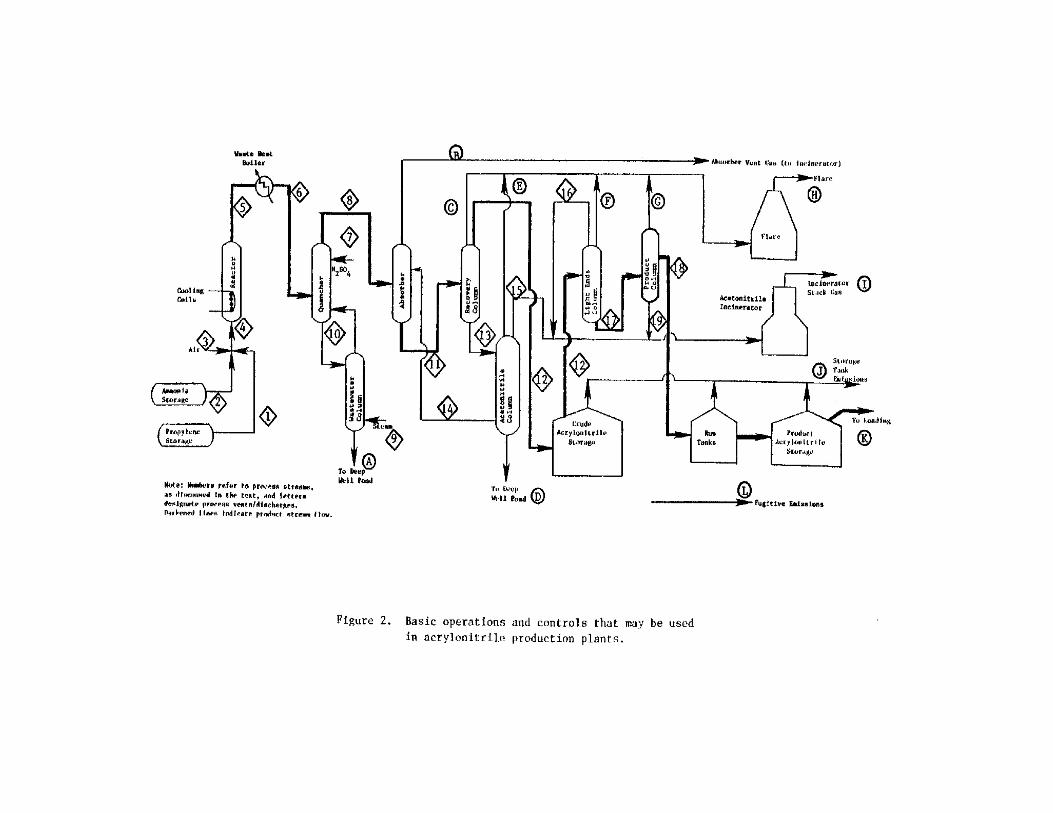
SECTION 4
EMISSIONS FROM ACRYLONITRILE PRODUCTION
The potential for acrylonitrile emissions occurs both during the
production of the monomer and during its consumption as a raw material
in other manufacturing processes: This section includes a detailed
description of the acrylonitrile production process along with possible
J), and during loading into railroad tank cars and barges (Vent K).
These emissions are generally uncontrolled but in some cases safety
considerations dictate the use of recovery systems.7 Water scrubbers
used for this purpose in acrylonitrile production facilities have
demonstrated removal efficiencies up to 99 percent.8 Floating roof
tanks may also be used in place of fixed roof tanks to reduce
acrylonitrile emissions up to 95 percent.8
Emissions of acrylonitrile may also occur from fugitive sources
(Vent L) and from deep well ponds. Fugitive sources, such as leaks from
pumps, compressors, and valves, are normally uncontrolled but can be
minimized if fugitive leaks are detected and corrected. Fugitive
emissions and various control measures used to minimize them are
described in Reference 9.9 Emissions of acrylonitrile from deep well
ponds are usually very small because the wastewater discharged to the
deep well pond contains less than 0.02 percent acrylonitrile and the
surface is covered with high molecular weight oil to prevent the escape
of most VOC vapors.2,8,10
Emission Factors--
Table 6 gives acrylonitrile emission factors before and after the
application of possible controls for a hypothetical plant using the
Sohio process.8 The hypothetical plant is assumed to use thermal
incineration for the control of absorber vent gases, flares for the
control of column purge vents, and water scrubbers for the control of
storage tank and loading emissions. The values presented for controlled
fugitive emissions are based on the assumption that leaks from valves
and pumps, resulting in concen trations greater than 10,000 ppm
acrylonitrile on a volume basis, are detected and that appropriate
measures are taken to correct the leaks. Only the startup emissions are
uncontrolled. Uncontrolled emission factors are based on the
22
TABLE 6. UNCONTROLLED AND CONTROLLED ACRYLONITRILE EMISSION FACTORSFOR A HYPOTHETICAL ACRYLONITRILE PRODUCTION PLANTa,b
Uncontrolled Controlled Assumed Emission Emission Emission Factor Control Device Reduction Factor Ventc Source g/Kg or Technique (%) g/Kg
B Absorber vent (normal) 0.10 Thermal incinerator 98n 0.002 (startup)(e) 0.187 No control 0.187 C,E,F,G Column vents 5.00 Flare (vent H) 98o 0.10 J Storage vents Crude acrylonitrile 0.048g Water scrubberh 99a 0.00048 Acrylonitirle run tanks 0.128g Water scrubberh 99a 0.00128 Acrylonitirle storage 0.531g Water scrubberh 99a 0.00531 K Handlingi,j
Tank car loadingk 0.167 Water scrubber 99a 0.0017 Barge loadingl 0.150 Water scrubber 99a 0.0011 L Fugitivem 0.806 Detection and 71 0.238 correction of major leaks TOTAL 7.07 0.537 (a) Reference 8 (b) Hypothetical plant produces 180,000 Mg (198,000 tons) per year of acrylonitrile monomer. It also produces 21,600 Mg (23,800 tons) of hydrogen cyanide and 5000 Mg (5500 tons) of acetonitrile per year as byproducts. Values in Table are based on 8760 hours/year of operation. Values are based on the assumption that 40 percent of the hydrogen cyanide and all of the acetonitrile produced are incinerated. Note that any given acrylontrile production plant may vary in configuration and level of control from this hypothetical facility. The reader is encouraged to contact plant personnel to confirm the existence of emitting operations and control technology at a particular facility prior to estimating emissions therefrom. (c) See Figure 2 (d) g of acrylonitrile emitted per kg acrylonitrile produced. (e) Startup emissions are vented to the atmosphere to prevent possible explosion in absorber lines. This factor represents average rates for entire year, based on 8 startups (two reactors, each with four startups) per year lasting 1 hour. Thus, during startup each reactor emits 4250 kg (1930 lb)acrylonitrile. (f) Storage tanks were assumed to be fixed-roof types, half full, with diurnal temperature variation of 11°C (20°F), and a bulk liquid temperature of 27°C (81°F). Assumes the following tank sizes and turnover rates: Tank Volume (m3) Turnovers per year per tank ------ ------------- ----------------------------- Crude Acrylonitrile 2500 6 Acrylontrile run 380 294 tanks (two tanks) Acrylonitrile storage 5680 20 (two tanks) (g) Reference 11. Section 4.3. Supplement 12. (h) Floating-roof tanks are also used in some cases to control storage emissions, with reported reductions of uncontrolled emission of greater than 95 percent. (i) Reference 11. Section 4.4. Supplement 9. (j) Assumes 55% of acrylonitrile loaded into tank cars and 45% onto barges. (k) Assumes submerged loading and dedicated normal service. (l) Assumes submerged loading. (m) Process pumps and valves are potential sources of fugitive emissions of acrylonitrile. The assumedequipment list (reference 8) and emission factors (reference 12) are as follows: Emission factor (kg\hr), each pump/valve Equipment Uncontrolled Controlled 25 pumps in light-liquid service 0.12 0.03 100 pipeline valves in gas/vapor service 0.021 0.002 500 pipeline valves in light-liquid service 0.010 0.003 40 safety/relief valves in gas/vapor service 0.16 0.061 Controlled emission factors are based on the assumption that leaks encountered during monthly inspections having VOC concentrations of at least 10,000 ppmv are corrected within 15 days. (n) Reference 14 and 15. (o) Reference 16.
23
assumptions given in footnotes to Table 6. An annual average emission
rate of acrylonitrile from the hypothetical controlled facility shown in
Table 6 is slightly greater than 0.5 g/kg of acrylonitrile produced,
including startup emissions. However, some facilities in the
acrylonitrile production industry may have controlled emission factors
two to three times higher than the hypothetical plant described here due
to differences in operating conditions or control methods.2,13
24
REFERENCES FOR SECTION 4
1. Anguin, M. T. and S. Anderson (Acurex Corporation). AcrylonitrilePlant Air Pollution Control. EPA-600/2-79-048. U.S. EnvironmentalProtection Agency. Research Triangle Park, North Carolina.February 1979.
2. Tierney, D. R., T. R. Blackwood, and G. E. Wilkins. StatusAssessment of Toxic Chemicals: Acrylonitrile. EPA-600/2-79-210a. U.S. Environmental Protection Agency. Cincinnati, Ohio. December1977.
3. Industrial Process Profiles for Environmental Use: Chapter 6: TheIndustrial Organic Chemicals Industry. EPA-600/2-77-023f. U.S.Environmental Protection Agency. Cincinnati, Ohio. February 1977.
4. Stanford Research Institute International. 1983 Directory ofChemical Producers. Menlo Park, California. 1983. pp. 410-411.
5. Lowenbach, W. and J. Schleslinger. Acrylonitrile Manufacture:Pollutant Prediction and Abatement. (Prepared for U. S.Environmental Protection Agency, EPA Contract No. 68-01-3188). TheMITRE Corporation. McLean, Virginia. February 1978.
6. Blackford, J. L, et al. Chemical Conversion Factors and Yields,Commercial and Theoretical. Second Edition. Stanford ResearchInstitute. Menlo Park, California. 1977. p. 6.
7. Control Techniques for Volatile Organic Emissions from StationarySources. EPA-450/2-78-022. U.S. Environmental Protection Agency.Research Triangle Park, North Carolina. May 1978.
8. Key, J. A. and F. T. Hobbs (IT Enviroscience). Acrylonitrile.Organic Chemical Manufacturing Volume 10: Selected Processes.EPA-450-3/80-028e. U.S. Environmental Protection Agency. ResearchTriangle Park, North Carolina. December 1980.
9. V0C Fugitive Emissions in Synthetic Organic ChemicalsManufacturing Industry--Background Information for ProposedStandards. EPA-450/3-80-033a. U.S. Environmental ProtectionAgency. Research Triangle Park, North Carolina. November 1980.
10. Hughes, T. W. and D. A. Hour (Monsanto Research Corp.). SourceAssessment: Acrylonitrile Manufacture (Air Emissions). EPAContract No. 68-02-1874. September 1977. pp. 21-22.
11. Compilation of Air Pollutant Emission Factors. 3rd Edition. AP-42.U.S. Environmental Protection Agency. Research Triangle Park,North Carolina. August 1977.
25
12. Dubose, D. A. et al (Radian Corporation). Emission Factors andFrequency of Leak Occurrence for Fittings in Refinery ProcessUnits. EPA-600/2-79-044. U.S. Environmental Protection Agency.Research Triangle Park, North Carolina. February 1979.
13. Suta, Benjamin (SRI International). Assessment of Human Exposuresto Atmospheric Acrylonitrile. Human Exposure to AtmosphericConcentrations of Selected Chemicals. EPA Contract No. 68-02-2835.U.S. Environmental Protection Agency. Research Triangle Park,North Carolina. August 1979.
14. Memo from Mascone, D. C., U. S. EPA to Farmer, J. R., U. S. EPA.June 11, 1980. Thermal Incinerator Performance for NSPS.
15. Memo from Mascone, D. C., U. S. EPA to Farmer, J. R., U. S. EPA.July 22, 1980. Thermal Incinerator Performance for NSPS, Addendum.
16. McDaniel, M. D. A Report on a Flare Efficiency Study, Volume 1(Draft). Engineering-Science. Austin, Texas. 1983.
26
SECTION 5
EMISSIONS FROM INDUSTRIES USING ACRYLONITRILE AS A FEEDSTOCK
This section describes various production processes using
acrylonitrile monomer as a feedstock and discusses the emissions
resulting from these processes. The processes included are acrylic and
modacrylic fiber production, production of ABS/SAN resins, production of
nitrile rubbers, and the production of acrylamide and adiponitrile. The
process descriptions included in this section are for hypothetical
plants generally achieving a high degree of monomer recovery and
emission control through the use of flashing, stripping, and scrubbing.
The reader should note, however, that all facilities may not be as
adequately equipped for monomer recovery and emissions control as these
hypothetical plants.
Acrylonitrile is also used as a feedstock in the production of
nitrile barrier resins, in the production of fatty amines, in the
cyanoethylation of alcohols and amines, in fumigant formulations, and as
an absorbent. However, the percentage of acrylonitrile consumed in
these miscellaneous processes is small and very limited information is
available concerning process descrip tions and emissions. Consequently,
no discussion of these miscellaneous processes is included in this
report.
ACRYLIC AND MODACRYLIC FIBER PRODUCTION1-9
The major use of the acrylonitrile monomer is as a feedstock for
acrylic and modacrylic fiber production. Acrylic fibers are classified
as having greater than 85 weight percent acrylonitrile while modacrylic
fibers have less than 85 percent but greater than 35 percent
acrylonitrile. Comonomers used in the production of acrylic fibers
include methyl acrylate, methyl methacrylate, and vinyl acetate.
Vinylidene chloride and vinyl chloride are the most often
27
used comonomers in the production of modacrylic fibers. In the
remainder of this section, acrylic and modacrylic fibers will both be
referred to as acrylic.
Process Descriptions
In the production of acrylic fibers, the acrylonitrile and
comonomers are first polymerized using either a suspension or a solution
polymerization process. The resulting polymer is then spun into fibers
using either wet spinning or dry spinning techniques. Finally, the spun
fibers must be treated to remove excess solvent and to improve fiber
characteristics. The fiber treating process has a negligible
contribution to acrylonitrile emissions and is not discussed in this
section. Each of the polymerization and spinning processes is discussed
below.
Polymerization--
In 1977-78 the suspension polymerization process accounted for 87
percent of the total acrylic fiber production, while the solution
process accounted for 13 percent. Each of these processes may be
carried out in either a batch or a continuous mode. A general block
flow diagram is shown in Figure 3 indicating the process operations
involved in the suspension and solution polymerization processes. In
the suspension process, insoluble beads of polymer are formed in a
suspension reactor. Unreacted monomer is removed from the polymer by
flashing/stripping and the polymer is filtered, dried, and then
dissolved in solvent in preparation for spinning. In the solution
process, polymer formed in the reactor is soluble in the spinning
solvent present. Reactor effluent, after monomer recovery, is therefore
ready for spinning. Several steps, including filtration and drying, are
thus avoided using the solution process.
Suspension Polymerization--
A more detailed schematic flow diagram of a hypothetical
suspension polymerization process is shown in Figure 4. Slight
variations in this process may occur from plant to plant, however.
30
In this process acrylonitrile and comonomers are mixed and then passed
to the polymerization reactors along with water, suspending agents,
stabilizers, and catalysts. The reactor is equipped for heat removal
and is agitated to maintain the monomers in suspension in the water.
The reaction of acrylonitrile monomers in the suspension reactor is
typically carried out to about 65 to 85 percent completion, and results
in the formation of insoluble beads of polymer. Essentially all of the
comonomers are consumed in this process.
Unreacted acrylonitrile monomer is removed from the polymer
product by flashing and stripping. Approximately 80 percent of the
unreacted monomer is released overhead from the vacuum flash tank and
nearly all of the remaining acrylonitrile is released overhead by
countercurrent contact with steam in the slurry stripper. The
acrylonitrile-containing streams from the vacuum flash tank and slurry
stripper are passed to the acrylonitrile recovery unit. Some
acrylonitrile is also recovered from the reactor and slurry stripper
overhead condensers and decanters (not shown in
Figure 4).
The stripper bottoms, containing stripped polymer and water, are
pumped via a filter feed tank to the filtration unit, typically
consisting of two rotary vacuum filters. These filters serve to
concentrate the polymer in a cake to reduce the load in the dryers and
to remove most of the residual acrylonitrile from the polymer. Filter
cake from the first filter is reslurried with water and transferred to
the second filter. Filter cake from the second filter is pelletized and
filtrate is transferred to the acrylonitrile recovery system. The
pelletized polymer is then dried with steam heated air and stored in
bins or silos. In preparation for spinning into fiber, the dry polymer
is mixed with solvent and dissolved to form spinning dope which is then
filtered, deaerated, and pumped to the spinneret which is a metal plate
perforated with 200-30,000 holes of approximately 0.008 cm (0.003 in)
diameter.
31
Acrylonitrile recovery is accomplished by the use of an
absorber/stripper system. Acrylonitrile-containing gases from the
pelletizer, and recovered acrylonitrile tank are scrubbed with water in
the acrylonitrile absorber. Absorber overhead is vented to the
atmosphere and absorber bottoms are sent to the acrylonitrile stripper,
along with filtrate from the rotary filters. Acrylonitrile monomer is
released overhead along with a considerable amount of steam. An
overhead condenser followed by a decanter serves to separate the
acrylonitrile from the water. The water-rich phase is treated and
recycled to the stripper and the acrylonitrile-rich phase is recycled to
the recovered acrylonitrile tank.
Solution Polymerization--
The basic process flow diagram for solution polymerization is
similar to that for suspension polymerization (shown in Figure 4) except
that the filtration, pelletizing, and drying steps are eliminated. In
the solution polymerization process, acrylonitrile and comonomers are
fed to a monomer mix tank where they are dissolved in a solvent.
Typical solvents include organic solvents such as dimethylformamide
(DNF), dimethylacetamide (DMAC) or acetone, and concentrated aqueous
solutions of zinc chloride, sodium thiocyanate, or nitric acid. The
monomer/solvent solution is transferred to the polymerization reactors
where addition of an initiator causes the reaction to proceed. Polymer
formed by solution polymerization is soluble in the solvent. The polymer
solution is flashed to release about 80 percent of the unreacted
acrylonitrile monomer, and then pumped to the top of the stripper where
virtually all of the remaining acrylonitrile monomer is stripped
overhead by countercurrent contact with steam. The stripper overhead
stream is vented to the atmosphere. Finally, the stripped polymer
solution is heated, filtered, deaerated and pumped to the spinnerets to
be spun into fibers.
An absorber/stripper system is used to recover unreacted
acrylonitrile from gases generated by storage tanks, the reactor, and
the vacuum flash tank. This absorber/stripper system is similar to
32
the one used in the suspension polymerization process. The
acrylonitrile-containing gases are scrubbed with water in the
acrylonitrile absorber and overhead from the absorber is vented to the
atmosphere. Bottoms from the absorber are pumped to the acrylonitrile
stripper where acrylonitrile monomer is stripped overhead with steam.
Phase separation is accomplished by means of a condenser and decanter,
and the water-rich phase is returned to the stripper while the
acrylonitrile-rich phase is recycled to the polymerization reactor.
Spinning--
Acrylic and modacrylic fibers may be spun in either a wet spinning
or a dry spinning process. Wet spinning may be carried out in a batch
or a batch-continuous process whereas dry spinning is always a batch
process. Both the wet spinning and dry spinning processes require that
the polymer be dissolved in solvent, forming a viscous solution that is
then forced through a spinneret. Common spinning solvents are acetone
and dimethylformamide.
The main difference between the wet and dry spinning processes is
the method used to remove solvent from the fiber upon extrusion from the
spinneret. In the dry spinning process, the solvent is evaporated by
hot gases, while in the wet spinning process the solvent is removed by
leaching or washing.2 The wet fibers produced by wet spinning must then
be dried in an air dryer. The resulting fibers from both processes are
then stretched, crimped, and thermally stabilized.
Vaporized solvent from the dry spinning process is condensed and
recycled to the dissolving step of the polymerization process. Wash
water from the wet spinning process, containing solvent and some
residual acrylonitrile monomer, is directed to a solvent recovery unit
and an acrylonitrile recovery unit. In some cases, the exhaust from the
fiber dryer is also sent to the solvent recovery unit.
33
Emissions
Acrylonitrile emissions from the combination of suspension
polymerization followed by wet spinning occur at the pelletizer and
polymer dryer. Potential emissions of acrylonitrile from the
polymerization reactor, flash tank, slurry stripper, filter feed tank
and filters, and pelletizer are reduced by passing the vent gases
through an absorber/stripping system for acrylonitrile recovery.
Acrylonitrile emissions from this absorber/stripping system are very
low. Emissions from the combination of solution polymerization followed
by wet spinning may occur at the stripper and in the spinning and
washing steps. Potential acrylonitrile emissions from the
polymerization reactor and flash tank are reduced by passing the vent
gases through the acrylonitrile recovery unit. Some of the emissions
associated with spinning and washing may also be reduced in this manner.
Monomer storage tank vents for both processes are generally controlled
by flares. Fugitive emissions from pumps, valves, and seals may also
occur during the production of acrylic fibers. Information concerning
acrylonitrile emissions from the dry spinning process is not available.
Also, no information concerning reactor startup emissions is available.
Many of the controls typically employed at acrylic fiber
production facilities are integral parts of the process design. Most of
the controls are actually recovery systems which reduce downstream
emissions in addition to recovering monomer for reuse in the process.
Strippers, scrubbers, condensers, and flash systems are used for
recovery purposes. In the suspension process, unreacted monomer is also
removed from the polymer in the washing and filtration steps. Most of
these controls remove unreacted monomer from the polymer thereby
reducing the amount of monomer that would otherwise be released in the
drying ovens. The drying ovens are generally uncontrolled due to the
high cost of treating large air flows with dilute VOC concentrations.
34
Sufficient information is not available to develop emission
factors for the various process operations given above. The reader is
encouraged to contact State and local air pollution control agencies
where these types of plants are located and the specific plants of
interest to determine the extent of potential acrylonitrile emissions
from fiber production.
Source Locations
Five companies at six locations produce acrylic fibers. A list of
these companies and their locations is given in Table 7.10
Acrylonitrile monomer is not produced at any of these facilities.
The manufacturers of acrylonitrile products such as acrylic and
modacrylic fibers may change over time due to changes in market
conditions. Publications such as the SRI Directory of Chemical Producers
and the Chemical Marketing Reporter are good sources of up-to-date
information on chemical producers. Chemical trade assoc!ations such as
the Chemical Manufacturers Association, the Acrylonitrile Group, and the
Synthetic Organic Chemical Manufacturers Association would also be good
contacts to determine the status of the acrylonitrile products industry.
PRODUCTION OF SAN AND ABS RESINS1-9,11
Acrylonitrile monomer is used extensively in the production of
styrene-acrylonitrile (SAN) resins and acrylonitrile-butadiene-styrene
(ABS) resins. SAN resins may contain up to about 35 weight percent
acrylonitrile. ABS resins are two-phase systems formed by grafting SAN
onto a rubber phase and then blending the grafted rubber with SAN. The
amount of rubber in ABS varies from 5 to 30 percent. Most SAN produced
is used captively in the production of ABS although some is marketed
separately. Only one producer manufactures SAN exclusively for sale on
the merchant market.
35
TABLE 7. DOMESTIC ACRYLIC FIBER PRODUCERS IN 198310
Company Location
American Cyanamid Co. Milton, Florida
Badische Corporation Williamsburg, Virginia
E. I. duPont de Nemours and Co., Inc.
Camden, South Carolina
Waynesboro, Virginia
Tennessee Eastman Co. Kingsport, Tennessee
Monsanto Co. Decatur, Alabama
NOTE: This listing is subject to change as market conditions change,
facility ownership changes, plants are closed down, etc. The reader
should verify the existence of particular facilities by consulting
current listings and/or the plants themselves. The level of
acrylonitrile emissions from any given facility is a function of
variables such as capacity, throughput, and control measures, and
should be determined through direct contacts with plant personnel.
36
Process Descriptions And Emissions
ABS and SAN resins are produced by emulsion, suspension, and mass
polymerization processes. Currently most ABS and most SAN for captive
use are produced using the emulsion polymerization process. Mass
polymerization is the method most often used to produce SAN for sale in
the marketplace.
Process and operating conditions used to produce SAN and ABS may
vary considerably from plant to plant depending on the composition of
the finished product. Likewise, emissions and methods of emission
control and monomer recovery may vary from plant to plant. For this
reason, it is difficult to give precise process descriptions for each of
the various polymerization processes. The process descriptions and flow
diagrams presented in this section are, therefore, very general in
nature. Brief discussions of each of the processes used to produce SAN
are included in the section followed by a discussion of methods used to
produce ABS.
San Production Processes--
The three polymerization processes used to produce SAN are
emulsion, mass, and suspension polymerization. Simplified block
diagrams of these three processes are shown in Figure 5.
SAN produced via the emulsion polymerization process may be formed
by either a batch or a continuous process. In either process, styrene
and acrylonitrile monomers are fed to the reactor along with an
emulsifier, deionized water, and catalysts. The polymerization reaction
takes place at about 70-100°C (160-212°F) and proceeds to 90-98 percent
conversion. Unreacted monomers are recovered from the resulting SAN
latex by steam stripping. The SAN latex is then subjected to
coagulation, filtration, and drying before the solid SAN product is
produced. Potential acrylonitrile emission points include storage
tanks, polymerization reactors, the latex stripper, the coagulation
38
tank, filters, and the dryer. However, acrylonitrile emissions from
these points are generally reduced by incinerating/flaring the vent gas
streams and/or passing them through a water scrubber.
The mass polymerization process used to produce SAN is generally a
continuous process with inherently low acrylonitrile emissions. The
styrene and acrylonitrile monomer mixture is heated together with an
appropriate modifier-solvent and pumped to the polymerizaton reactor.
Polymerization takes place in the presence of a catalyst in an agitated
reactor maintained at about 275 kPa (40 psia) and 100-200°C (212-390°F).
The reaction proceeds only to about 20 percent conversion. The
conversion is limited in order to control viscosity. The reaction
products are discharged to a series of devolatilizers that separate the
SAN polymer from unreacted monomers and the modifier-solvent.
Devolatilization is carried out under vacuum at temperatures of 120 to
260°C (250 to 500°F). Inerts, unreacted monomers, and the
modifier-solvent are removed overhead from the devolatilizers.
Overheads are condensed and passed through a refrigerated styrene
scrubber to recover monomers and modifier-solvent which are then
recycled to the feed tank. The refrigerated scrubber vent gas contains
a negligible amount of acrylonitrile.
The bottoms from the final devolatilizer are almost pure polymer
melt. This polymer is extruded and chopped into pellets. The pellets
are then blended, milled and compounded. Acrylonitrile and other
volatile organic compounds that are released from the milling operation
are passed through a scrubber prior to being vented to the atmosphere.
Acrylonitrile emissions from the feed tank, reactor, and devolatilizers
are vented to an incinerator/flare.
SAN produced via the suspension polymerization process may be
produced in either a batch or a continuous mode, although batch
processes are predominant. In this process, styrene and acrylonitrile
monomers are dispersed mechanically in water containing catalysts and
suspending agents. The monomer droplets are polymerized while suspended
by agitation, and insoluble beads of polymer are formed. The
39
temperature of the polymerization reactor ranges from 60-150°C
(140-300°F) and a monomer conversion of 95 percent is normally achieved.
Unreacted monomer is recovered by flashing and steam or vacuum
stripping. The solid and liquid phases of the polymer slurry are
separated by centrifugation and/or filtration. The solid phase is then
dried in a rotary dryer and the dried polymer is finished by
mechanically blending in dyes, antioxidants and other additives using
extruders and rolling mills. The polymer sheets from these operations
are then pelletized and packaged. Although emissions of acrylonitrile
from the various process operations described above would be expected,
information detailing these emissions and methods of control is
unavailable.
ABS Production Processes--
As mentioned previously, ABS is a two-phase system consisting of
an SAN-grafted rubber blended with SAN. Polybutadiene is normally used
as the backbone or substrate rubber but nitrile rubbers and
styrene-butadiene rubbers may also be used. The backbone rubber may be
produced at the ABS facility for captive use or it may be purchased from
other sources. Like SAN, ABS may be produced by the emulsion, mass, and
suspension polymerization processes.
ABS by Emulsion Polymerization-- There are three different routes by
which ABS may be produced using the emulsion polymerization process.
Block diagrams for each of these routes are depicted in Figure 6. In
the first route pictured in Figure 6, styrene and acrylonitrile
monomers are grafted onto the backbone rubber, usually polybutadiene
rubber. The SAN-grafted rubber latex is then blended with SAN resin
latex (produced by emulsion polymerization) followed by coagulation,
washing, filtration, and drying.
In the second route shown in Figure 6, the SAN-grafted rubber is
coagulated, washed, filtered and dried. Then the dry grafted-rubber is
mechanically blended with dry SAN solid. Solid SAN copolymer produced
by the emulsion, suspension or mass polymerization processes may be
utilized in the mechanical blending step. In the third route shown in
41
Figure 6, the SAN-graft and styrene-acrylonitrile copolymerization occur
in the same reaction vessel. The resulting ABS latex is then
coagulated, washed, filtered and dried.
Each of these routes uses a water scrubber to recover unreacted
acrylonitrile monomer from the emulsion polymerization reactor vent gas.
Acrylonitrile emissions from the water scrubber, coagulation tank, wash
tanks, and filters are incinerated/flared before being released to the
atmosphere. Generally, emissions from the polymer dryer are
uncontrolled.
ABS by Mass Polymerization-- A block flow diagram for ABS produced via
the mass polymerization process is shown in Figure 7. The rubber used
in this process must be soluble in the styrene and acrylonitrile
monomers. The rubber is dissolved in the monomers along with initiators
and modifiers and then passed to the prepolymerizer, an agitated vessel
where a 20 to 30 percent conversion of the monomers occurs. The
resulting monomer-polymer mixture is pumped directly to the mass
polymerization reactor where an overall conversion of 50 to 80 percent
is achieved. Unreacted monomers are removed from the polymer in a
series of devolatilizers, and are then condensed and recycled to a
prepolymerizer. To produce the product resin, ABS polymer is extruded
and chopped into pellets. Acrylonitrile emission points include the
polymerization reactor, devolatilizers, and monomer vapor condenser.
Vent incineration is typically used to reduce acrylonitrile emissions
from this process.
ABS by Suspension Polymerization-- The suspension polymerization process
used to produce ABS is shown by a block flow diagram in Figure 8. This
process is sometimes called a mass-suspension process because the
dissolving and prepolymerizations steps are identical to those of the
mass polymerization process. The monomer/polymer mixture from the
prepolymerizer is passed to the suspension reactor to which is added
water and suspending agents. When the desired conversion is reached,
the reaction products are cooled, dewatered by filtration or
centrifugation, and dried. Possible acrylonitrile emission sources from
44
this process include the prepolymerizer, polymerization reactor,
dewatering system, and the dryer. Emissions from these sources are
often reduced by incineration.
Emissions Summary
Acrylonitrile emission sources vary depending upon the type of
polymerization process used: emulsion, mass, or suspension. Possible
emission sources and typical methods of control were previously
discussed for each of the various polymerization processes used to
produce SAN and ABS. In addition to acrylonitrile emissions from the
various process operations, fugitive emissions of acrylonitrile from
pumps, valves, and flanges may also occur. Sufficient information was
unavailable to develop emission factors for specific facilities, process
operations, or fugitive emission sources. Also, no information
concerning reactor startup emissions is available in the literature for
ABS/SAN production processes. The reader is encouraged to contact State
and local air pollution control agencies where these types of plants are
located and the specific plants of interest to determine the extent of
potential acrylonitrile emissions from ABS/SAN production.
Source Locations
ABS/SAN resins are produced by three companies at 10 locations. A
list of these producers and their locations is given in Table 8.12
Although all ABS manufacturers have SAN production capabilities,
essentially all of this SAN is used captively in the production of ABS.
The manufacturers of acrylonitrile products such as ABS and SAN
resins may change over time due to changes in market conditions.
Publications such as the SRI Directory of Chemical Producers and the
Chemical Marketing Reporter are good sources of up-to-date information
on chemical producers. Chemical trade associations such as the Chemical
45
TABLE 8. DOMESTIC ABS/SAN RESIN PRODUCERS IN 198312
Company Location Products
SAN ABS
Borg-Warner Corp. Ottawa, Illinois yes
Washington, West Virginia - yes
Port Bienville, Mississippi - yes
Dow Chemical Gales Ferry, Connecticut (b) - yes
Ironton, Ohio yes
Midland, Michigan (a) yes yes
Pevely, Missouri yes
Torrance, California yes
Monsanto Co. (c) Addyston, Ohio (a) yes yes
Muscatine, Iowa yes
(a) Produce some SAN for the merchant market. Most SAN is used captively
in ABS production.
(b) This plant is also referred to as the Allyns Point plant.
(c) Reference 12 indicates that Monsanto has an ABS resin plant in
Springfield, Massachusetts; however, information obtained from Reference
13 and Reference 14 has more recently indicated that this facility no
longer produces ABS resins.12-14
NOTE: This listing is subject to change as market conditions change, facility
ownership changes, plants are closed down, etc. The reader should
verify the existence of particular facilities by consulting current
listings and/or the plants themselves. The level of acrylonitrile
emissions from any given facility is a function of variables such as
capacity, throughput, and control measures, and should be determined
through direct contacts with plant personnel.
46
Manufacturers Association, the Acrylonitrile Group, and the Synthetic
Organic Chemical Manufacturers Association would also be good contacts
to determine the status of the acrylonitrile products industry.
NITRILE RUBBER AND LATEX PRODUCTION1-9
Another use for acrylonitrile monomer is in the production of
nitrile elastomers, in both crumb rubber and latex form. The rubbers
and latexes are manufactured using the emulsion copolymerization of
acrylonitrile and butadiene. Acrylonitrile content in these nitrile
products may range from 20 to 50 weight percent but is typically in the
30 to 40 percent range. The acrylonitrile content of a particular
product is dictated by the end use of the product. The oil resistance
of the product increases with increasing acrylonitrile content, but the
low temperature flexibility decreases.
Process Descriptions
Nitrile rubbers and latexes are produced by emulsion
polymerization in batch or continuous reactors. This process involves
polymerization of acrylonitrile and butadiene monomers, recovery of
unreacted monomers, and coagulation, washing and drying. A schematic
flow diagram of the process is shown in Figure 9.
Polymerization--
Acrylonitrile and butadiene monomers are fed to the agitated
polymerization reactors along with a soap solution and additives.
Additives include catalysts and activators, which initiate and promote
the polymerization reaction, and modifiers which control polymer
properties such as viscosity and molecular weight (chain length). Early
in the reaction the soap provides the microscopic bubbles called
micelles in which the reaction takes place. Later, the soap covers the
rubber particles formed and keeps the mixture in liquid form. The soap
solution is used to produce an emulsion of monomers in an aqueous
medium.
48
The polymerization process is carried out under either cold
conditions [4-7°C and 101 to 205 kPa (40-45°F and 0 to 15 psig)] using
ammonia refrigeration to remove heat of reaction, or under hot
conditions [35-49°C and 377 to 515 kPa (95-120°F and
40 to 60 psig)] using cooling water. Reaction times may vary
considerably (from an hour to several days) depending on the ingredients
used. When the desired level of conversion has been attained, the
reaction is stopped by destroying the catalyst and adding a shortstop
solution. Two common shortstop ingredients are sodium dimethyl
dithiocarbamate and hydroquinone. Monomer conversion for rubber
products is typically 60 to 90 percent while 95 percent conversion is
typical for latex products. The resulting reaction mixture, a milky
white emulsion called latex, is sent to blowdown tanks where
antioxidants are normally added to maintain product quality.
Unreacted Monomer Recovery--
Unreacted monomers must be removed from the latex, requiring a
series of flashing and stripping operations. First, the latex is
subjected to several vacuum flash steps where most of the unreacted
butadiene and some acrylonitrile are released. Then the latex is
usually stripped with steam under vacuum to remove residual butadiene
and most of the unreacted acrylonitrile. A thorough flash/stripping
operation will remove better than 99 percent of the unreacted monomers
from the latex. Stripped latex at about 43 to 55°C (110 to 130°F) is
pumped to blend tanks.
Butadiene and acrylonitrile monomers released from the latex
flashing/stripping operation are passed through a water absorber along
with reactor process vent gases, effecting separation of the two
monomers. Butadiene is passed to a separate recovery unit and the
monomer is then recycled to the process. Acrylonitrile monomer recovery
is normally accomplished by combining the acrylonitrile-containing
streams from the absorber and latex stripper and passing the combined
stream through a steam stripper. Acrylonitrile released overhead from
the stripper is condensed and recycled to the process.
49
Coagulation, Washing And Drying--
The coagulation, washing, and drying steps are omitted if the
desired end product is latex. These steps are necessary, however, for
the production of rubber. In the production of rubber, latex is first
coagulated into a slurry of fine crumbs by the addition of various salts
or acids which destroy the protective soap cover. Coagulated crumb
rubber is quenched and then separated from the coagulation liquor in a
shaker screen and the liquor is recycled to the coagulation tank along
with fresh acid or brine. The screened crumb is washed with water in a
reslurry tank to remove residual coagulation liquor from the rubber.
The crumb rubber slurry is again dewatered on a second screen. Although
not depicted in Figure 9, a vacuum filter or press may be used further
to dewater the crumb which typically has a moisture content of 10 to 50
percent. The crumb rubber is then dried in a gas-fired or steam-heated
dryer where it is contacted with hot air. Finally, the nitrile rubber
product is weighed and pressed into bales in preparation for shipment.
Emissions
Essentially all of the process operations shown in Figure 9 are
potential sources of acrylonitrile emissions. However, emissions from
these sources are generally reduced through a combination of monomer
recovery by absorption and stripping, and vent incineration or flaring.
Unreacted acrylonitrile and butadiene, released from the polymerization
reactor as well as from the latex during flashing/stripping, are
recovered and recycled to the process. Acrylonitrile emissions from the
acrylonitrile absorber and stripper are negligible. Acrylonitrile
emissions from polymerization reactors, the blowdown tank, the quench
tank, the coagulation tank, wet screens, the reslurry tank, and the
dryer are typically vented to an incinerator or flare. Fugitive emission
sources include storage tanks, pumps, valves, flanges and drains.
Sufficient information is not available to develop emission factors for
various facilities, process operations, or fugitive emission sources.
Also, no information is available in the literature to accurately
quantify reactor startup emissions. The reader is encouraged to contact
State
50
and local air pollution control agencies where these types of plants are
located and the specific plants of interest to determine the extent of
potential acrylonitrile emissions from nitrile rubber and latex
production.
Source Locations
Nitrile rubber is produced by five companies at seven locations.
These companies and their locations are listed in Table 9.15,16 The
manufacturers of acrylonitrile products such as nitrile rubber and latex
may change over time due to changes in market conditions. Publications
such as the SRI Directory of Chemical Producers and the Chemical
Marketing Reporter are good sources of up-to-date information on
chemical producers. Chemical trade associations such as the Chemical
Manufacturers Association, the Acrylonitrile Group, and the Synthetic
Organic Chemical Manufacturers Association would also be good contacts
to determine the status of the acrylonitrile products industry.
PRODUCTION OF ADIPONITRILE17
Adiponitrile may be produced by as many as four processes;
however, only one of these processes involves the use of acrylonitrile.
Adiponitrile from acrylonitrile involves the hydrodimerization of
acrylonitrile in an electrochemical process. This process is used only
by Monsanto Company, who is also the original process developer.
The Monsanto electro-hydrodimerization (EHD) process is
represented by the following equation:
2H2C=CHCN + 2e- + 2H+ + NC(CH2)4CN.
This reaction takes place in an electrolytic cell, using
electrical energy to provide the impetus for the chemical reaction.
Either graphite and magnetite or cadmium and iron may be employed as
51
TABLE 9. DOMESTIC NITRILE ELASTOMER PRODUCERS IN 198315,16
Company Location
Copolymer Rubber and Chemical Corp. Baton Rouge, Louisiana
BF Goodrich Co. Akron, Ohio
Louisville, Kentucky
Goodyear Tire and Rubber Co. Akron, Ohio
Houston, Texas
Reichhold Chemical Cheswold, Delaware
Uniroyal, Inc. Painesville, Ohio
NOTE: This listing is subject to change as market conditions change,
facility ownership changes, plants are closed down, etc. The
reader should verify the existence of particular facilities by
consulting current listings and/or the plants themselves. The
level of acrylonitrile emissions from any given facility is a
function of variables such as capacity, throughput, and
control measures, and should be determined through direct
contacts with plant personnel.
52
cathodes and anodes, respectively. A tetraalkylammonium salt is used to
increase conductivity and to reduce the formation of byproduct
propionitrile by hydrogenation of acrylonitrile.
The reaction itself is carried out by rapidly pumping a two-phase
emulsion through the cathode-anode system. This two-phase emulsion
consists of an aqueous phase containing the conducting salt and small
amounts of acrylonitrile, and an organic phase containing acrylonitrile
and adiponitrile. After passing through the electrolytic cell, the
organic and aqueous phases are separated by distillation. The aqueous
phase containing the conducting salt is recycled, and adiponitrile is
recovered from byproducts, propionitrile, and biscyanoethyl ether. The
adiponitrile selectivity in this reaction is approximately 90 percent.
No process information is available to formulate acrylonitrile
emission factors for the Monsanto EHD adiponitrile process. The reader
is encouraged to contact State and local air pollution control agencies
where these types of plants are located and the specific plants of
interest to determine the extent of potential acrylonitrile emissions
from adiponitrile production.
The Monsanto plant where adiponitrile is produced by the EHD
process is located in Decatur, Alabama.18
PRODUCTION OF ACRYLAMIDE19
Acrylamide is produced on the industrial scale by the hydration of
acrylonitrile. As shown in Table 10, three companies at four locations
are currently producing acrylamide.20 Two hydration methods are
currently used in the United States: acid hydrolysis (partial
hydrolysis) and catalytic hydrolysis (direct hydrolysis).
In the acid hydrolysis process, acrylonitrile is reacted with
stoichiometric amounts of sulfuric acid (H2SO4) to form acrylamide
53
TABLE 10. DOMESTIC ACRYLAMIDE PRODUCERS IN 198320
Company Location
American Cyanamid Linden, New Jersey
Avondale, Louisianaa
Dow Chemical Midland, Michigan
Nalco Chemical Garyville, Louisiana
(a) This plant is also referred to in the literature as being located in
Westwego, Louisiana.
NOTE: This listing is subject to change as market conditions change,
facility ownership changes, plants are closed down, etc. The reader
should verify the existence of particular facilities by consulting
current listings and/or the plants themselves. The level of
acrylonitrile emissions from any given facility is a function of
variables such as capacity, throughput, and control measures, and
should be determined through direct contacts with plant personnel.
54
sulfate. The acrylamide sulfate intermediate is then reacted with
ammonia (NH3) forming acrylamide and ammonium sulfate. The equation
governing the acid hydrolysis reaction is:
CH2=CHCN + H2SO4 • H2O ---> CH2=CHCONH2 • H2SO4
2NH3
-------> CH2=CHCONH2 + (NH4)2SO4
Ammonium sulfate and acrylamide are then separated by several
involved crystallization steps.
In the catalytic hydrolysis process, acrylamide is produced by the
direct hydrolysis of acrylonitrile over copper catalysts in an aqueous
solution. The advantage of this method is that, after filtering off the
catalyst and distilling to remove unreacted acrylonitrile, an
essentially pure aqueous acrylamide solution is obtained. This solution
can then be used directly or further concentrated depending upon its end
use.
Information concerning emissions of acrylonitrile from the
production of acrylamide is unavailable. The reader is encouraged to
contact State and local air pollution control agencies where these types
of plants are located and the specific plants of interest to determine
the extent of potential acrylonitrile emissions from acrylamide
production.
55
REFERENCES FOR SECTION 5
1. Click, C.N. and D.O. Moore. Emission, Process and ControlTechnology Study of the ABS/SAN, Acrylic Fiber, and NBR Industries(prepared for U.S. Environmental Protection Agency. Contract No.68-02-2619, Task 6). Pullman Kellogg. Houston, Texas. April 1979.
2. Considine, D. Chemical and Process Technology Encyclopedia.McGraw-Hill, New York, New York. 1974. pp. 27-28.
3. Encyclopedia of Polymer Science and Technology. Volume 1: AcrylicFibers. p. 352.
4. 1980 Kline Guide to the Chemical Industry. pp. 343-344.
5. Work, R. W. Man-Made Textile Fibers. In: Riegel's Handbook ofIndustrial Chemistry. Kent, J. (ed). Van Nostrand Reinhold. NewYork. 1974. p. 332.
6. Development Document for Proposed Effluent Limitations Guidelineand New Source Performance Standards for the Synthetic ResinsSegment of the Plastics and Synthetic Materials ManufacturingPoint Source Category.U.S. Environmental Protection Agency.EPA-940/1-73-01O. September 1973. p. 71.
7. Click, C.N. and D.O. Moore. Emission, Process and ControlTechnology Study of the ABS/SAN, Acrylic Fiber, and NBR Industries(prepared for U.S. Environmental Protection Agency. Contract No.68-02-2619, Task 6). Pullman Kellogg. Houston, Texas. April 1979.pp. 80-85.
8. Work, R. W. Man-Made Textile Fibers. In: Riegel's Handbook of
Industrial Chemistry. Kent, J. (ed). Van Nostrand Reinhold. NewYork. 1974. pp. 348-351.
9. U. S. International Trade Commission. Synthetic Organic Chemicals,U. S. Productions and Sales. 1979.
10. Stanford Research Institute International. 1983 Directory ofChemical Producers. Menlo Park, California. 1983. p. 593.
11. Kirk-Othmer Encyclopedia of Chemical Technology. Third Edition.Volume 1. Acrylonitrile Polymers. John Wiley and Sons, New York,New York. 1980. pp. 427-456.
12. Stanford Research Institute International. 1983 Directory ofChemical Producers. Menlo Park, California. 1983. pp. 814 and 831.
13. Letter and attachments from Romano, R. R., Chemical ManufacturersAssociation to Lahre T., U. S. EPA. August 11, 1983. Comments onemission factor reports.
56
14. Telecon. Lahre, T. F., U. S. EPA with Massachusetts Department ofEnvironmental Quality Engineering. December 6, 1983. Status of theMonsanto-Springfield ABS resin plant.
15. Stanford Research Institute International. 1983 Directory ofChemical Producers. Menlo Park, California. 1983. p. 569.
16. Letter and attachments from Blower, K. E., Standard Oil to Lahre,T. F., U. S. EPA. June 13, 1983. Comments on the draftacrylonitrile emission factor report.
17. Weissermel, K. and H. Arpe. Industrial Organic Chemistry:Important Raw Materials and Intermediates. Verlag Chemie, NewYork, New York. 1978. pp. 216-219.
18. Stanford Research Institute International. 1983 Directory ofChemical Producers. Menlo Park, California. 1983. p. 412.
19. Weissermel, K. and H. Arpe. Industrial Organic Chemistry:Important Raw Materials and Intermediates. Verlag Chemie, NewYork, New York. 1978. pp. 270-272.
20. Stanford Research Institute International. 1983 Directory ofChemical Producers. Menlo Park, California. 1983. p. 409.
57
SECTION 6
SOURCE TEST PROCEDURES
The results of a literature survey and review of References 2
through 25 indicate that gas chromatography is the analytical method
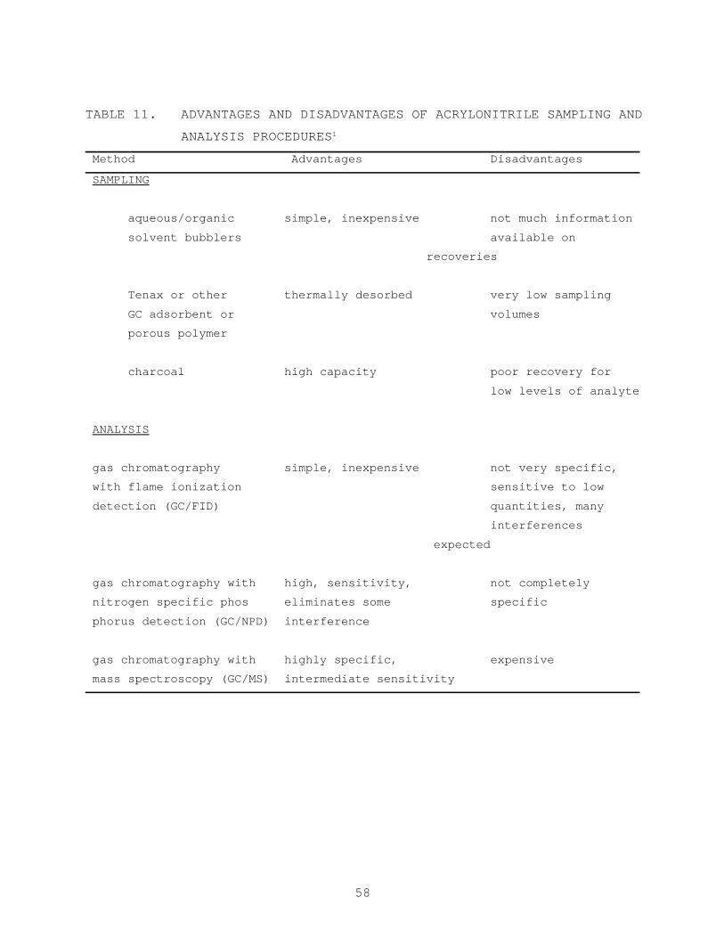
generally preferred for acrylonitrile.1 Table 11 lists several sampling
and analytical techniques evaluated, along with their advantages and
disadvantages. The major differences among the various methods are in
sample collection and preconcentration, and the choice of detector used
for quantification.
The need to concentrate samples is determined by the level of the
acrylonitrile in the sample and by the detection limit of the particular
instrumentation chosen for quantification. When acrylonitrile levels
are low, provisions must be built into the method for the determination
of these low levels.
LITERATURE REVIEW OF SAMPLING METHODS
Although several researchers have used aqueous or aqueous/organic
solvent mixtures in bubblers or impingers for sampling acrylonitrile,
the most widely reported trapping methods are those employing solid
adsorbent tubes of charcoal, Tenax®, or other porous polymers such as
those used for gas chromatographic supports. Of these solid adsorbents,
the one which has received the most attention and is used most often is
Tenax-GC®. However, the data presented in the various publications
surveyed in this review indicate that the retention characteristics of
acrylonitrile on Tenax® are such that the safe sampling volumes would be
quite small. The safe sampling volume is approximately 3 liters of air
per gram (48 ft3 per pound) of Tenax® for a flow rate of 5 to 200 ml/min
at 25°C (77°F). Because of the small sample, the concentration factor
would also be very small.
58
TABLE 11. ADVANTAGES AND DISADVANTAGES OF ACRYLONITRILE SAMPLING AND
ANALYSIS PROCEDURES1
Method Advantages Disadvantages
SAMPLING
aqueous/organic simple, inexpensive not much information
solvent bubblers available on
recoveries
Tenax or other thermally desorbed very low sampling
GC adsorbent or volumes
porous polymer
charcoal high capacity poor recovery for
low levels of analyte
ANALYSIS
gas chromatography simple, inexpensive not very specific,
with flame ionization sensitive to low
detection (GC/FID) quantities, many
interferences
expected
gas chromatography with high, sensitivity, not completely
nitrogen specific phos eliminates some specific
phorus detection (GC/NPD) interference
gas chromatography with highly specific, expensive
mass spectroscopy (GC/MS) intermediate sensitivity
59
For Poropak N, a porous polymer often used for GC supports, the
breakthrough volume was reported and found to be 3 to 5 liters of air at
100 ml/min at 25°C. The maximum recommended sampling volume for this
sorbent was estimated to be 50 to 75 percent of the breakthrough volume,
or 1.5 to 2.5 liters. With such small concentrations, the sensitivity of
the measurement technique becomes very important.
Most sampling of air and exhaust samples for acrylonitrile is done
using charcoal. The adsorptive capacity of charcoal for acrylonitrile is
on the order of 4 percent by weight according to one report (NIOSH
method), but this can vary depending upon the characteristics of the
adsorbent. The main problem with charcoal adsorption tubes is the
possibility of losses of small amounts of acrylonitrile upon desorption
with organic solvents.
A recent investigation of recoveries of acrylonitrile from
charcoal concluded that acrylonitrile could be recovered (>90 percent)
with good precision from charcoal at a level of 16 µg per 100 mg
charcoal using a mixture of acetone and carbon disulfide instead of
methanol for desorption.13 This correspondends to vapor levels of 0.5
ppm for a 15 liter air sample. Below the 16 µg/100 mg charcoal level,
recoveries were generally less than 90 percent for vapor phase
application of acrylonitrile.
Because of possible low recoveries of acrylonitrile on charcoal,
large sampling volumes might be required to achieve lower detection
limits, but, at the same time, backup sections of charcoal adsorbent
would be required should the levels be higher than expected.
LITERATURE REVIEW OF ANALYTICAL PROCEDURES
The three possible choices of detectors for GC separation of
acrylonitrile are flame ionization detection, nitrogen specific
detection, and low or high resolution mass spectrometry, with or without
selected ion monitoring.
60
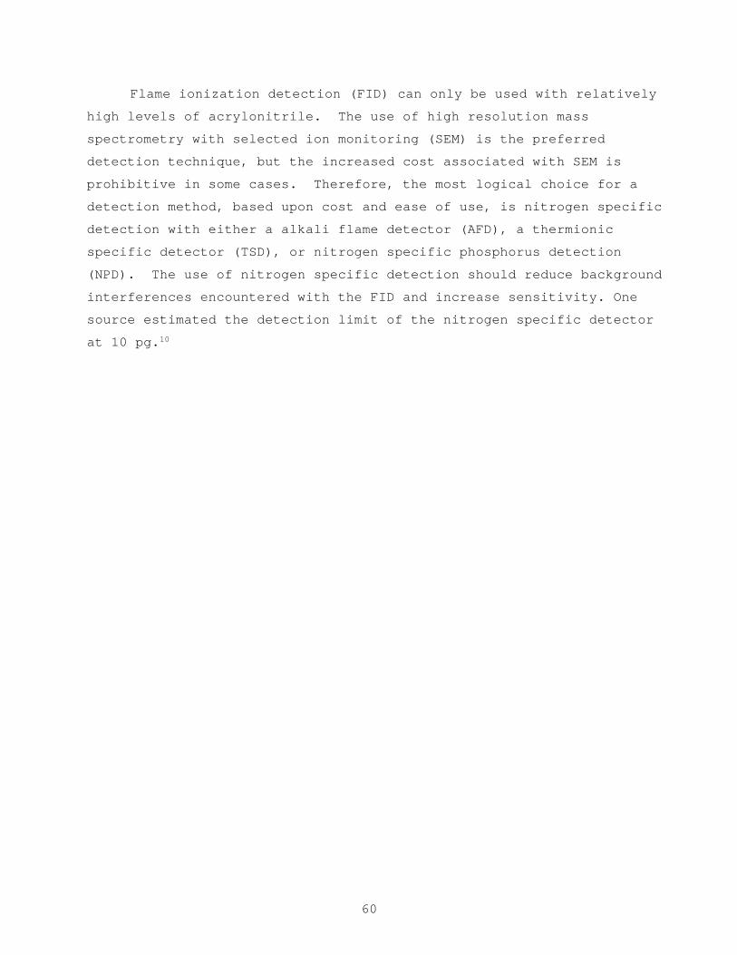
Flame ionization detection (FID) can only be used with relatively
high levels of acrylonitrile. The use of high resolution mass
spectrometry with selected ion monitoring (SEM) is the preferred
detection technique, but the increased cost associated with SEM is
prohibitive in some cases. Therefore, the most logical choice for a
detection method, based upon cost and ease of use, is nitrogen specific
detection with either a alkali flame detector (AFD), a thermionic
specific detector (TSD), or nitrogen specific phosphorus detection
(NPD). The use of nitrogen specific detection should reduce background
interferences encountered with the FID and increase sensitivity. One
source estimated the detection limit of the nitrogen specific detector
at 10 pg.10
61
REFERENCES FOR SECTION 6
1. Cooke, M. et al. (Battelle); J.C. Harris and V. Grady (Arthur D.Little). Candidate Techniques for Sampling and Analysis forTwenty-One Suspect Carcinogens. Draft Report. U.S. EnvironmentalProtection Agency. Research Triangle Park, North Carolina. September 28, 1982.
2. Kogaczewska, T. Acrylonitrile Determination in Air. Med. Pr..27(2) 115-126, 1976. (In Polish).
3. Nagarova, V.I. and L.K. Nakrop. Determination of Acrybutrile inAir. M. Anal. K. Kach. Prod. Khum. Prom., 5:28-29, 1978. (InRussian).
4. Knodo, M. Sampling and Measurement of Organic Cyanogen Compounds.Kankyo Hoken Reporti Environ. Health Rept., 30:83-88, 1974. (InJapanese).
5. Fasitta, V. and G. Ticciardello. Determination of Acetonitrile andAcrylonitrile in Air by Gas Chromatography. Ann. Inst. Super.Sanita., 13(1-2):245-248, 1977. (In Italian).
6. Schultzl, O., J.J. Prater, and S.R. Ruddell. Sampling and Analysisof Emissions for Stationary Sources. I. Odor and TotalHydrocarbons. JAPCA, 25(9):925-932, 1975.
7. Penton, S. Measurement of Acrylonitrile in Industrial Air by GasChromatography. Varian Instrument Appl., 13(2):4-5, 1979.
8. Sawicki, E. Organic Solvent Vapors in Air. Analytical Method.Health Lab. Sci., 12(4):394-402, 1975.
9. Gomez, C.R. and B.G. Linder. Quantitative Determination ofAcrylonitrile in Work Areas. Traub. Simp. Hyg. Ind., 3:495-506,1979. (In Spanish).
10. Marano, R.S., S.D. Levine and T.M. Harvey. Trace Determination ofSubnanogram Amounts of Acrylonitrile in Complex Matrices by GasChromatography with a Nitrogen Selective Detector. Anal. Chem.,50:(13), 1948-1950, 1978.
11. Oomens, A.C. Experience With a Dual Detector Headspace GasChromatograph for Acrylonitrile Analysis. Appl. Headspace GasChromatography., 1980, pp. 111-116.
12. Taylor, D.G., coord. NIOSH Manual of Analytical Methods, Vol. 3,2nd ed., 1977. pp. 5156-1 to 5156-8.
62
13. Gagnum, Y.T., and J.C. Posner. Recovery of Acrylonitrile fromCharcoal Tubes at Low Levels. Am. Ind. H . Assoc. J.,40(10):923-925, 1979. 14. Russell, J.W. Analysis of Air PollutantsUsing Sampling Tubes and Gas Chromatography. Environ. Sci.Technol., 9(13):1175-1178, 1975.
14. Russell, J.W. Analysis of Air Pollutants Using Sampling Tubes andGas Chromatography. Environ. Sci. Technol., 9(13):1175-1178,1975.
15. Parsons, J.S., and S. Mitzner. Gas Chromatographic Method forConcentration and Analysis of Traces of Industrial OrganicPollutants in Environmental Air and Stacks. Environ. Sci.Technol., 9(12):1053-1058, 1975.
16. Brown, R.H., and C.J. Purnell. Collection and Analysis of TraceOrganic Vapor Pollutants in Ambient Atmospheres. The Performanceof Tenax-GC Adsorbent Tube. J. Chromatogr., 178(1):79-90, 1979.
17. Campbell, D.N., and R.H. Moore. The Quantitative Determination ofAcrylonitrile, Acrolein, Acetonitrile and Acetone in WorkplaceAir. Am. Ind. Hyg. Assoc. J., 40(10) 904-909, 1979.
18. Schabel, X.H., and R. Casper. Headspace Gas Chromatography inIndustrial Hygiene. Appl. Headspace Gas Chromatogr., 1980, pp.32-40.
19. Casper, R.H. Special Analytical Methods with Respect to IndustrialHygiene. Annu. Meet. Proc.-Int. Inst. Symp. Rubber Prod., 18,Paper No. 6, 1977, pp. 15.
20. Jacobs, H., and R. Syrjola. The Use of Infrared Analyzers forMonitoring Acrylonitrile. J. Am. Ind. Hyg. Assoc., 39(2) 161-165,1978.
21. Syyrjola, R.J. Quantitative Analysis of Atmospheric PollutantsUsing a Microcomputer Controlled Single Beam InfraredSpectrometer. Envir. Anal., 1977, pp. 111-125.
22. Satoh, S. Gas Chromatography-Mass Spectrometric Identification ofOrganic Compounds and Determination of Acrylonitrile in the Air ofthe Kawasaki Industrial Area. Koenshu-Iyo Masu Kenkywkui.,4:113-120, 1979.
23. Koosker, A.A.M. Measurement of Organic Gases in the Atmosphere.PT-Procestech., 34(7):409-415, 1979.
63
24. Harris, J.C., M.J. Hayes, P.L. Levins, and D.B. Lindsay,EPA/IERL-RTP Procedures for Level 2 Sampling and Analysis ofOrganic Materials EPA-6O0/7-79-033, U.S. Environmental ProtectionAgency, 1979. pp. 165.
25. Thrun, K.E., J.C. Harris, C.E. Rechsteiner, D.J. Sorling. Methodsfor Level 2 Analysis by Organic Compound Category,EPA-600/7-81-029, U.S. Environmental Protection Agency, ResearchTriangle Park, North Carolina, March 1981. pp. 123-131.
IMATING AIR WISSIONS FROM SOURCES OF KRYLONITRILE
)ffice Of Air Quality Planning And Standards
EPA Project Officer: Thomas F. Lahre
To aerist groups interested in iaveatoryial air uieeioae of various potentially toxic l ubetaacea , EPA is prepariq a eerie. of docuate l uch am thir to compile available iaformetioa oa eourcee ti eaieeiooe of theee rube taacee . This document deale mpecificelly with l crylooitrile. Itr intended l wlieace includee Federal, State cad locel air pollution pereonael end others intererted in locatin(l poteatiel emittere of l cryloaitrile emi in aakiag poae eetirtee of air eairaione therefrom.
Thir documat preaeate information oa 1) the typee of l oerceo that my emit acrylonitrile, 2) proceee verietioae ard releeee pointe thet uy be expected within there aourcee, cad 3) aveileble eeieeioae inforntion indicetiw the potential for l cryloaitrile mleeee into the l ir from eech . operation.
Acrylonitrile Sources Locating Sources of Emieaiona Toxic Subataaceo