LPS 1237: Issue 1.1 Requirements for control panels for electric motor driven pumps used in automatic sprinkler installations
This standard specifies the requirements for LPCB approval of control panels for electric motor driven pumps used in automatic sprinkler installations. LPCB approved control panels covered by this standard are to be used in stationary fire sprinkler pump sets which conform to the LPC rules for automatic sprinkler installations.
This Loss Prevention Standard is the property of BRE Global Ltd. and is made publicly available for information purposes only. Its use for testing, assessment, certification or approval must be in accordance with LPCB internal procedures and requires interpretation by BRE Global Ltd, LPCB and BRE experts. Any party wishing to use or reproduce this Loss Prevention Standard to offer testing, assessment, certification or approval must apply to BRE Global for training, assessment and a licence; a fee will normally be charged. BRE Global Ltd. will not unreasonably refuse such applications. BRE Global Ltd. accepts no responsibility for any un-authorised use or distribution by others of this Loss Prevention Standard and may take legal action to prevent such unauthorised use or distribution
3.1 General ........................................................................................................................... 6 3.2 Enclosure ........................................................................................................................ 6 3.2.1 Environmental protection ............................................................................................. 6 3.2.2 Access to control panel ................................................................................................ 6 3.2.3 Location ....................................................................................................................... 6 3.3 Power supply .................................................................................................................. 7 3.3.1 Mains feed ................................................................................................................... 7 3.3.2 Main switching components ......................................................................................... 7 3.3.3 Electric circuit protection devices ................................................................................. 7 3.4 Operational parameters ................................................................................................... 7 3.4.1 Automatic starting system ............................................................................................ 8 3.4.2 Emergency manual starting system. ............................................................................ 8 3.4.3 Test facility for manual starting .................................................................................... 8 3.4.4 Stopping the pump ...................................................................................................... 8 3.5 Outputs ........................................................................................................................... 8 3.5.1 Indicators ..................................................................................................................... 8 3.5.2 Meters – measurement indication ................................................................................ 9 3.6 Auxiliary and Supplementary Functions .......................................................................... 9 3.7 Documentation ................................................................................................................ 9
4 MARKING, LABELLING AND PACKAGING ......................................................................... 10 5 TYPE TESTING ................................................................................................................... 11
5.1 Function tests ................................................................................................................ 11 5.2 Simulation of power failure ............................................................................................ 11 5.3 Vibration testing ............................................................................................................ 11 5.4 Temperature tests ......................................................................................................... 12 5.5 Electrical safety checks (AC Circuits) ............................................................................ 12 5.6 Other tests .................................................................................................................... 13
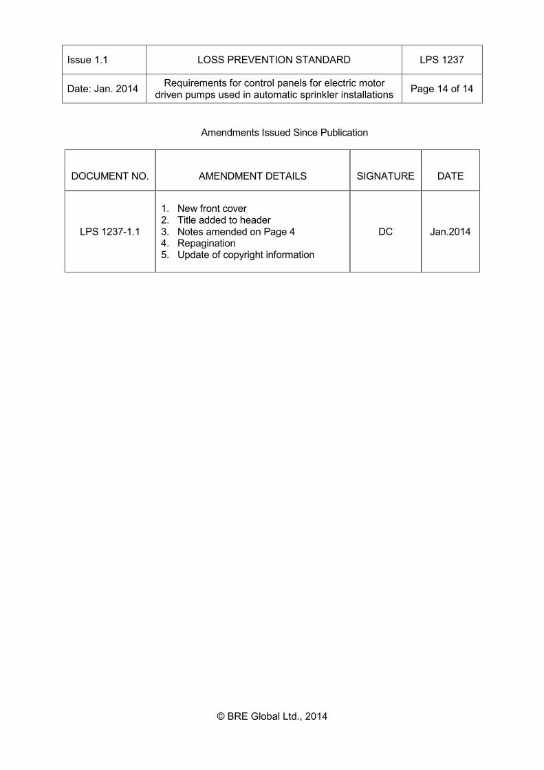
6 CLASSIFICATION AND DESIGNATION .............................................................................. 13 PUBLICATIONS REFERRED TO: .................................................................................................. 13 Table of amendments issued since publication ............................................................................... 14
Issue 1.1 LOSS PREVENTION STANDARD LPS 1237
Date: Jan. 2014 Requirements for control panels for electric motor driven pumps used in automatic sprinkler installations Page 2 of 14
This standard was approved by the LPC Fire and Security Board and Expert Group C. The following organisations participated in the preparation of this standard:- Association of British Insurers Association of Building Engineers Association of Chief Police Officers Association for Specialist Fire Protection British Automatic Fire Sprinkler Association British Security Industry Association BT Redcare Chief Fire Officers Association Door & Hardware Federation Electrical Contractors Association European Fire Sprinkler Network Fire Industry Association Health & Safety Executive International Fire Sprinkler Association Metronet Risk Engineering Data Exchange Group Royal and Sun Alliance Royal Institution of Chartered Surveyors
REVISION OF LOSS PREVENTION STANDARDS Loss Prevention Standards will be revised by issue of revised editions or amendments. Details will be posted on our website at www.redbooklive.com Technical or other changes which affect the requirements for the approval or certification of the product or service will result in a new issue. Minor or administrative changes (e.g. corrections of spelling and typographical errors, changes to address and copyright details, the addition of notes for clarification etc.) may be made as amendments. (See amendments table on page 14) The issue number will be given in decimal format with the integer part giving the issue number and the fractional part giving the number of amendments (e.g. Issue 3.2 indicates that the document is at Issue 3 with 2 amendments). USERS OF LOSS PREVENTION STANDARDS SHOULD ENSURE THAT THEY POSSESS THE LATEST ISSUE AND ALL AMENDMENTS.
FOREWORD This standard specifies the requirements for LPCB certification of controllers for electric driven fire pumps for use in automatic sprinkler systems to installation standards such as the “LPC Rules for Automatic Sprinkler Installations” incorporating BS EN 12845:2003 – “Fixed firefighting systems - Automatic sprinkler systems - Design, installation and maintenance”. LPCB listing and approval of products and services is based on evidence acceptable to LPCB:-
• that the product or service meets the standard • that the manufacturer or service provider has staff, processes and systems in place to
ensure that the product or service delivered meets the standard
and on:-
• periodic audits of the manufacturer or service provider including testing as appropriate • compliance with the contract for LPCB listing and approval including agreement to
rectify faults as appropriate
This standard is part of a series relating to pump sets. It should be read in conjunction with LPCB Scheme Document SD139 “Certification requirements for Pump Sets”
The control panel shall comply with the essential health and safety requirements of the 'Machinery Directive', and conform to the relevant regulatory requirements and standards listed below:
Harmonised Standards: BS EN292 Part 1 Safety of Machinery - Basic Concepts and General Principles of
Design BS EN292 Part 2 Safety of Machinery BS EN 809 Pumps and Pump Units for Liquids - Safety Requirements BS EN60204-1 Safety of Machinery - Electrical Equipment BS EN50081 Part 1 EMC Generic Emission - Residential, commercial & light
industrial BS EN50082 Part 2 EMC Generic Immunity - Industrial
Issue 1.1 LOSS PREVENTION STANDARD LPS 1237
Date: Jan. 2014 Requirements for control panels for electric motor driven pumps used in automatic sprinkler installations Page 4 of 14
NOTES Compliance with this LPS does not of itself confer immunity from legal obligations. Users of LPSs should ensure that they possess the latest issue and all amendments. LPCB welcomes comments of a technical or editorial nature and these should be addressed to “the Technical Director” at [email protected]. The BRE Trust, a registered charity, owns BRE and BRE Global. BRE Global and LPCB (part of BRE Global) test, assess, certificate and list products and services within the fire and security sectors. For further information on our services please contact BRE Global, Watford, Herts. WD25 9XX or e-mail to [email protected] Listed products and services appear in the LPCB “List of Approved Products and Services” which may be viewed on our website: www.redbooklive.com or by downloading the LPCB Red Book App from the App Store (for iPhone and iPad), from Google Play (for Android devices) or from the Windows Store (for Windows 8 Phones and Tablets from 2014).
This standard specifies LPCB’s requirements for the approval of control panels for electric driven fire pump sets for use in sprinkler systems conforming to sprinkler system installation standards, for example the “LPC Rules for automatic sprinkler systems” (incorporating EN 12845:2003 - Fixed firefighting systems - Automatic sprinkler systems - Design, installation and maintenance). This standard is not intended to cover all aspects of the design and build of a control panel. It is limited to addressing certain critical areas, which are known to affect the ability of sprinkler systems to perform and comply with installation codes. This standard is part of a series relating to several aspects of a pump set. It should be read in conjunction with the other appropriate standards:
Standard Status LPS 1240 – Pump Sets Publication pending LPS 1239 – Diesel Drivers Published – LPCB approved items available LPS 1131 – Bare shaft pumps Published – LPCB approved items available LPS 1238 – Electric Drivers No LPCB approved items available.
Intended for future publication. LPS 1236 – Control panels for Diesel drivers
Publication pending
LPS 1237 – Control panels for Electric drivers
This standard
This standard specifies the electric fire pump set controller requirements by:
• Detailing electric pump set controller requirements which are not covered by other fire protection standards.
• The detailing requirements in this standard will take precedence (with the exception of regulatory requirements, which must always take precedence) over any other requirements.
• Referencing the relevant standards
Suppliers of LPCB Approved Fire Pump Sets shall control and be responsible for the design, construction, testing, performance, provision of installation instructions and commissioning of their fire pump sets.
The installer of the approved fire pump set is responsible for the installation of the pump set in strict accordance with the manufacturer’s installation manuals and procedures. An LPCB approved sprinkler system installer, with sufficient knowledge and training in relation to the manufacturer’s product, should always be used.
Issue 1.1 LOSS PREVENTION STANDARD LPS 1237
Date: Jan. 2014 Requirements for control panels for electric motor driven pumps used in automatic sprinkler installations Page 6 of 14
Fire pump set – An assembly comprising at least a pump, driver or motor, partial wiring loom, drive coupling and a mounting and/or base, which is intended to supply water to an automatic sprinkler installation. Electric Pump Controller – The control panel that monitors demand for sprinkler system water, controls the electric motor start-up sequence when called upon, allows testing of pump set and monitors specified pump set system fault & alarm conditions.
3 REQUIREMENTS
3.1 General
Control panels shall be designed and manufactured to meet the requirements of this standard, referenced documents and the requirements of the applicable installation standard (typically LPC Rules for automatic sprinkler systems, incorporating BS EN 12845). Control systems shall be designed to operate correctly at ambient temperatures from 0°C to 50°C. Where the designer proposes a system that has to operate at temperatures outside this range, successful tests shall be carried out at the relevant extreme temperatures and consideration given to other factors affecting system performance should be considered.
3.2 Enclosure
3.2.1 Environmental protection
The control panel housing shall be in non-flammable material and provide a degree of protection at least equal to IP 54 (BS EN 60529:1992 - Specification for degrees of protection provided by enclosures (IP code)), or be suited to its environment where the conditions are more demanding.
3.2.2 Access to control panel
The enclosure door shall be fitted with a suitable locking device, requiring the use of a key or special tool, in order to restrict access to authorised personnel only. It shall not be possible to open the panel door without having first isolated the AC main supply.
3.2.3 Location
Controllers shall be located as close as practicable to the pump sets they control, and shall be within sight of the pump set. The controller must not be mounted directly on the pump set and must not be exposed to any undue sources of vibration.
Issue 1.1 LOSS PREVENTION STANDARD LPS 1237
Date: Jan. 2014 Requirements for control panels for electric motor driven pumps used in automatic sprinkler installations Page 7 of 14
The main AC supply switch operating handle shall be outside the housing of the equipment, and interlocked with the enclosure door. The switch shall be capable of being locked in the on position. This switch shall be clearly labelled as follows:
“SPRINKLER PUMP MOTOR SUPPLY - NOT TO BE SWITCHED OFF IN THE EVENT OF FIRE.”
Lettering for the above shall be at least 10mm high and shall be white on a red background.
The metal earth for the enclosure shall be connected directly to a terminal which provides for connection to an earthing point. This terminal shall be labelled- earth symbol. The fuse or circuit breaker ratings shall be clearly shown at a point near the devices.
3.3.2 Main switching components
• Main contactors shall be selected for utilization category AC3 according to IEC 60947 - Low-
voltage switchgear and control gear. • Isolators/Fuse switches shall be selected for utilization category AC23. • Starters employing the Autotransformer method of reduced voltage starting shall be rated for
a minimum of 15 starts per hour.
3.3.3 Electric circuit protection devices
High rupturing capacity fuses shall be fitted to the controller to protect the sprinkler pump circuits. Fuses shall be capable of carrying the stalled motor current for a period of not less than 75% of the period needed for the motor windings to fail. The fuse-ratings shall be clearly shown at a point near the fuses themselves. Any no-volt release mechanism shall be of the automatic resetting type so that on restoration of the supply, the motor can be restarted automatically if the trunk main pressure falls. NOTE: MAGNETIC AND THERMAL TRIPS SHALL NOT BE USED.
3.4 Operational parameters
The control panel shall ensure the automatic and manual operation, control and monitoring of:-
• Motors in the pump assembly • Its own logic and components
Issue 1.1 LOSS PREVENTION STANDARD LPS 1237
Date: Jan. 2014 Requirements for control panels for electric motor driven pumps used in automatic sprinkler installations Page 8 of 14
Normal operation must be ensured at temperatures between 0°C and 50°C or over a wider temperature range if specifically requested by the designer. The controller shall be provided with a stop pushbutton. When released, if a low pressure or emergency manual start demand condition is present, the pump shall restart.
3.4.1 Automatic starting system
Automatic start-up shall be by means of a contact which opens to initiate a start. This shall be triggered by a de-energised pressure switch signal. The controller shall start the fire pump automatically on receipt of a signal indicating pressure drop in the fire protection system and the pump set shall continue to run until shut down manually.
3.4.2 Emergency manual starting system.
An over-ride emergency manual start facility shall be provided, protected by means of a hinged or frangible cover. 3.4.3 Test facility for manual starting
A control shall be provided to enable the pump set to be periodically tested without breaking the frangible element or receiving a pressure drop signal. This control shall not interfere with the ability of the pump to operate as specified in 3.4.1 & 3.4.2.
3.4.4 Stopping the pump
Consistent with BS EN 12845 10.7.5.2 it shall only be possible to stop the pump by manual intervention.
3.5 Outputs
3.5.1 Indicators
Visual indication is to be provided by solid state indicators having clearly visible labels with relevant data, as shown in Table 1.
The principle of visual indication used for safety equipment is to be as follows:-
Green indicator Healthy condition
Amber indicator Fault - the device in question is
defective and is not able to operate normally. Action required.
Red indicator Alarm- Immediate action required.
Issue 1.1 LOSS PREVENTION STANDARD LPS 1237
Date: Jan. 2014 Requirements for control panels for electric motor driven pumps used in automatic sprinkler installations Page 9 of 14
As an alternative, healthy, fault & alarm information may be given by an alpha numeric display, together with a Red, Amber and Green LED to identify status of current display. In addition, the following data shall be capable of being transmitted over a given distance:
a) 'PUMP ON DEMAND' output signal, signifying that the system pressure switch requires
the pump to start. b) 'SUPPLY FAILURE' output signal, signifying a phase failure c) ‘PUMP RUNNING‘ output signal, signifying the operation of the pump. d) ‘START FAILURE‘ output signal, signifying low discharge pressure.
Table 1 – Indicator lamps TITLE
LAMP COLOUR
FUNCTION AUDIBLE
AC Supply Healthy Green Indicates that the main supply is available on all three phases. Shall also indicate control supply healthy.
No
Pump on Demand Green Indicates that an initiation signal is present, that the motor should be either starting or running.
No
Pump Running Green Indicates that the Motor is running No Start Failure Red Indicates no or low discharge pressure No
3.5.2 Meters – measurement indication
The following parameters must be measured independently to an accuracy of ±5% with the actual measurements being displayed:-
- The full load running current of the motor, by means of an ammeter having an overload
scale of 6 times full load current. - For all the measuring equipment, the normal functional ranges and units (eg. “A” for
Amperes or “v” for volts) must be stated, preferably by direct display on the dial.
3.6 Auxiliary and Supplementary Functions
Any device or function of a supplementary nature provided in the equipment and not covered by this present specification shall not interfere with the functional requirements set out by the specification and referenced documents; they shall further comply with the data relating to them.
3.7 Documentation
General Requirement for guidance:
• All schematics and drawings shall be numbered and indexed. • Any modification carried out to the equipment, to the schematics and/or to the drawings
must be covered by a change to the revision level (letter or number). LPCB must be notified of all changes which may affect the approval)
Issue 1.1 LOSS PREVENTION STANDARD LPS 1237
Date: Jan. 2014 Requirements for control panels for electric motor driven pumps used in automatic sprinkler installations Page 10 of 14
• A list of all the drawing and schematic numbers must be provided. • All documents must be in the English language.
The following shall be provided:
1 A technical operating sheet 1.1 Detailed explanation of the operation of each of the circuits (monitoring, surveillance,
start-up, etc.) 1.2 Description of electrical characteristics : mains power voltage, breaking capacity of
contacts available to the user, power consumption, etc) 1.3 Description of possible external connections (indicators, inputs, etc) 1.4 Description of how to start the electric pump 2 Commissioning instructions 3 Operating instructions (explanation of indicator lamps, trouble-shooting instructions, in
the event of an alarm or malfunction) 4 Instructions covering checks, maintenance and storage 5 Electrical and key component schematics 5.1 Manufacturers recommended functional test procedures (routine 6 Manufacturing drawings 6.1 Drawings showing views of the panel from the front, from above and from the side,
showing the indicator lamps, pushbuttons and inscriptions (a photograph shall also be provided of the front face)
6.2 Sectionalised drawing of the panel, showing the positions of the various items and devices (these shall be labelled)
6.3 Drawing showing the positions of the terminal blocks and cabling, labelled with cross-reference to the schematics. Each drawing shall have the dimensions marked on and be accompanied by a listing of all the items making up the equipment and protection, where this is appropriate (paint, varnish, etc)
7 Means to safely disable motor & panel for service and maintenance activities. 8 Test certificates, where applicable, showing compliance with Directives listed on page
three.
4 MARKING, LABELLING AND PACKAGING
The controller housing shall have a data plate, positioned visibly and showing:- - Manufacturer’s name or trademark - Manufacturer’s address - Model designation serial number - Year of manufacture - LPCB approval mark - the nominal voltage for the main power supply source - rating (KW) of starter
Issue 1.1 LOSS PREVENTION STANDARD LPS 1237
Date: Jan. 2014 Requirements for control panels for electric motor driven pumps used in automatic sprinkler installations Page 11 of 14
The manufacturer shall submit a complete panel to the LPCB, including:-
• Cabling - test harness to enable testing; The designer shall also provide a technical dossier covering the items listed in 3.7.
5.1 Function tests
Verification tests shall be carried out to confirm that all the functionality required by this standard and referenced documents is provided by the controller. While carrying out the functional test, the controller shall be connected to a test motor, in order to prove phase rotation is correct. Finally with the motor disconnected, a functional test is to be carried out at 85% of rated voltage.
5.2 Simulation of power failure
Simulation of power failure, followed by restoration to ensure false starts do not occur, (test to be repeated 5 times).
5.3 Vibration testing
PURPOSE
The purpose of this test is to evaluate the ability of the components of a controller to withstand mechanically and to function formally when they are subjected to vibrations, which may occur under normal operating conditions in the installation, or during transportation. APPARATUS AND METHOD OF OPERATION This test is carried out with a vibrating device, used at a frequency of 20 Hz with a peak-to-peak amplitude of 0.8mm - that is, an acceleration equivalent to 0.64g. The equipment, positioned in its normal operating plane, is subjected to vibrations for a period of 30 minutes, perpendicular to its plane of attachment and then for thirty minutes in two orthogonal directions parallel to this plane. REQUIREMENTS In the course of this test, the equipment must remain stable. At the end of the test, the equipment must:-
- satisfy the necessary functional tests.
- reveal no defect or change which might, in time, affect its performance.
Issue 1.1 LOSS PREVENTION STANDARD LPS 1237
Date: Jan. 2014 Requirements for control panels for electric motor driven pumps used in automatic sprinkler installations Page 12 of 14
PURPOSE The temperature test is intended to verify operability of the controller at extremes of specified operating temperature range. METHOD OF OPERATION The equipment shall be placed in an environmental test chamber, with AC supply connected. A complete functional check should then be performed. The chamber shall then be brought up to a temperature of 50°C, which must be maintained for a period of 24 hours continuously. REQUIREMENTS During the course of the test the equipment must continue to operate as specified. At the end of the test, when brought back to ambient temperature, the equipment must:-
- not reveal any defect or change which might affect operation in the course of time. - satisfy the necessary functional tests, which should be carried out at 85% & 110% of
nominal voltage.
5.5 Electrical safety checks (AC Circuits)
- Perform an insulation resistance test at 1000 volts DC, between the incoming terminals and Earth.
THE INSULATION RESISTANCE MUST EXCEED 10 MEGOHM
- Using Dielectric high voltage test equipment, apply a voltage of 2500 volts between
the incoming terminals and Earth, for a period of one minute.
NO BREAKDOWN SHALL OCCUR
- Perform an insulation resistance test at 1000 Volts DC, between the outgoing terminals and Earth.
THE INSULATION RESISTANCE MUST EXCEED 10 MEGOHM
Issue 1.1 LOSS PREVENTION STANDARD LPS 1237
Date: Jan. 2014 Requirements for control panels for electric motor driven pumps used in automatic sprinkler installations Page 13 of 14
- Using Dielectric high voltage test equipment, apply a voltage of 2500 volts between the outgoing terminals and Earth, for a period of one minute.
NO BREAKDOWN SHALL OCCUR
- Perform an insulation resistance test at 1000 Volts DC, between the outgoing
terminals and Earth.
THE INSULATION RESISTANCE MUST EXCEED 10 MEGOHM
- Using Dielectric high voltage test equipment, apply a voltage of 2500 volts between the outgoing terminals and Earth, for a period of one minute.
NO BREAKDOWN SHALL OCCUR
- Remove any links fitted in the above tests.
5.6 Other tests
Where special designs or new manufacturing methods make it necessary to conduct additional testing, this is to be carried out after consultation with the manufacturer
6 CLASSIFICATION AND DESIGNATION
LPCB approved products will be listed in the Red Book of approved products and services and published on the product approval certificate supplied to the owner of the approval. Accompanying the listings & certificates will be any key supporting information in relation to the LPCB approval. Any special limitation to the approval will also be set out in the listing and on the certificate. For details of acceptable use of the mark, see LPCB publication PN103 “Use of the certification marks”
PUBLICATIONS REFERRED TO:
BS EN 292 Part 1 Safety of Machinery - Basic Concepts and General Principles of Design
BS EN 292 Part 2 Safety of Machinery BS EN 809 Pumps and Pump Units for Liquids - Safety Requirements BS EN 12845 Fixed firefighting systems - Automatic sprinkler systems -
Design, installation and maintenance BS EN 60204-1 Safety of Machinery - Electrical Equipment BS EN 50081 Part 1 EMC Generic Emission - Residential, commercial & light industrial BS EN 50082 Part 2 EMC Generic Immunity – Industrial IEC 60947 Low-voltage switchgear and control gear
For undated references please refer to the latest published issue.
Issue 1.1 LOSS PREVENTION STANDARD LPS 1237
Date: Jan. 2014 Requirements for control panels for electric motor driven pumps used in automatic sprinkler installations Page 14 of 14