40
For internal use only / 1 © Nokia Siemens Networks Power Control LTE Radio Parameters RL10 LTEPAR Pilot Düsseldorf CW 22 2010 & Reviewe
For internal use only / 1 © Nokia Siemens Networks
Power ControlLTE Radio Parameters RL10
LTEPAR Pilot Düsseldorf CW 22 2010 & Reviewed

For internal use only / 2 © Nokia Siemens Networks
Nokia Siemens Networks Academy
Legal notice
Intellectual Property RightsAll copyrights and intellectual property rights for Nokia Siemens Networks training documentation, product documentation and slide presentation material, all of which are forthwith known as Nokia Siemens Networks training material, are the exclusive property of Nokia Siemens Networks. Nokia Siemens Networks owns the rights to copying, modification, translation, adaptation or derivatives including any improvements or developments. Nokia Siemens Networks has the sole right to copy, distribute, amend, modify, develop, license, sublicense, sell, transfer and assign the Nokia Siemens Networks training material. Individuals can use the Nokia Siemens Networks training material for their own personal self-development only, those same individuals cannot subsequently pass on that same Intellectual Property to others without the prior written agreement of Nokia Siemens Networks. The Nokia Siemens Networks training material cannot be used outside of an agreed Nokia Siemens Networks training session for development of groups without the prior written agreement of Nokia Siemens Networks.
For internal use only / 4 © Nokia Siemens Networks
Module Objectives
After completing this module, the participant should be able to:
• Understand the basics of LTE PC
• Describe UL open loop PC part
• Discuss UL closed loop PC part (LTE 28)
• Identify DL power settings
• Analyze PSD
• Explain PC impacts on network performance
• Distinguish related parameters.

For internal use only / 5 © Nokia Siemens Networks
Module Contents
• Overview
• UL-PC: Overview
• UL-PC: PUSCH
• UL-PC: PUCCH
• UL-PC: SRS
• UL-PC: Control Scheme
• UL-PC: Closed Loop
• UL-PC: Parameters
• DL-PC: RL10
• DL-PC: PC on PDCCH

For internal use only / 6 © Nokia Siemens Networks
Module Contents
• Overview
• UL-PC: Overview
• UL-PC: PUSCH
• UL-PC: PUCCH
• UL-PC: SRS
• UL-PC: Control Scheme
• UL-PC: Closed Loop
• UL-PC: Parameters
• DL-PC: RL10
• DL-PC: PC on PDCCH
For internal use only / 7 © Nokia Siemens Networks
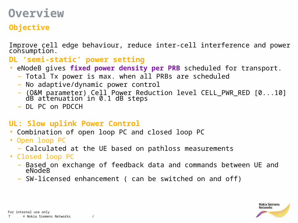
OverviewObjective
Improve cell edge behaviour, reduce inter-cell interference and power consumption.DL ‘semi-static’ power setting• eNodeB gives fixed power density per PRB scheduled for transport.
– Total Tx power is max. when all PRBs are scheduled– No adaptive/dynamic power control– (O&M parameter) Cell Power Reduction level CELL_PWR_RED [0...10] dB
attenuation in 0.1 dB steps– DL PC on PDCCH
UL: Slow uplink Power Control• Combination of open loop PC and closed loop PC• Open loop PC
– Calculated at the UE based on pathloss measurements• Closed loop PC
– Based on exchange of feedback data and commands between UE and eNodeB – SW-licensed enhancement ( can be switched on and off)

For internal use only / 8 © Nokia Siemens Networks
OverviewProcedure for Slow UL Power control• UE controls the Tx power to keep the transmitted power spectral density (PSD)
constant independent of the allocated transmit bandwidth (#PRBs)
• If no feedback from eNodeB ( in the PDCCH UL PC command) the UE performs open loop PC based on path loss measurements
• If feedback from eNodeB the UE corrects the PSD when receiving PC commands from eNodeB ( in the PDCCH UL PC command)
PC commands ( up and down) based on UL quality and signal level measurements
• Applied separately for PUSCH, PUCCH
• Scope of UL PC is UE level ( performed separately for each UE in a cell)
1) Initial TX power level
2) SINR measurment
3) Setting new power offset4) TX power level adjustment with the new offset
For internal use only / 9 © Nokia Siemens Networks
Module Contents
• Overview
• UL-PC: Overview
• UL-PC: PUSCH
• UL-PC: PUCCH
• UL-PC: SRS
• UL-PC: Control Scheme
• UL-PC: Closed Loop
• UL-PC: Parameters
• DL-PC: RL10
• DL-PC: PC on PDCCH
For internal use only / 10 © Nokia Siemens Networks
UL-PC: Overview
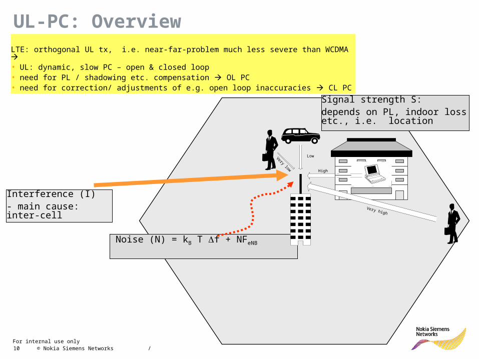
LTE: orthogonal UL tx, i.e. near-far-problem much less severe than WCDMA • UL: dynamic, slow PC – open & closed loop • need for PL / shadowing etc. compensation OL PC• need for correction/ adjustments of e.g. open loop inaccuracies CL PC
Interference (I)- main cause: inter-cell
Signal strength S:depends on PL, indoor loss etc., i.e. location
Noise (N) = kB T f + NFeNB
Very low
Low
High
Very high

For internal use only / 11 © Nokia Siemens Networks
Module Contents
• Overview
• UL-PC: Overview
• UL-PC: PUSCH
• UL-PC: PUCCH
• UL-PC: SRS
• UL-PC: Control Scheme
• UL-PC: Closed Loop
• UL-PC: Parameters
• DL-PC: RL10
• DL-PC: PC on PDCCH
For internal use only / 12 © Nokia Siemens Networks
UL-PC: PUSCH
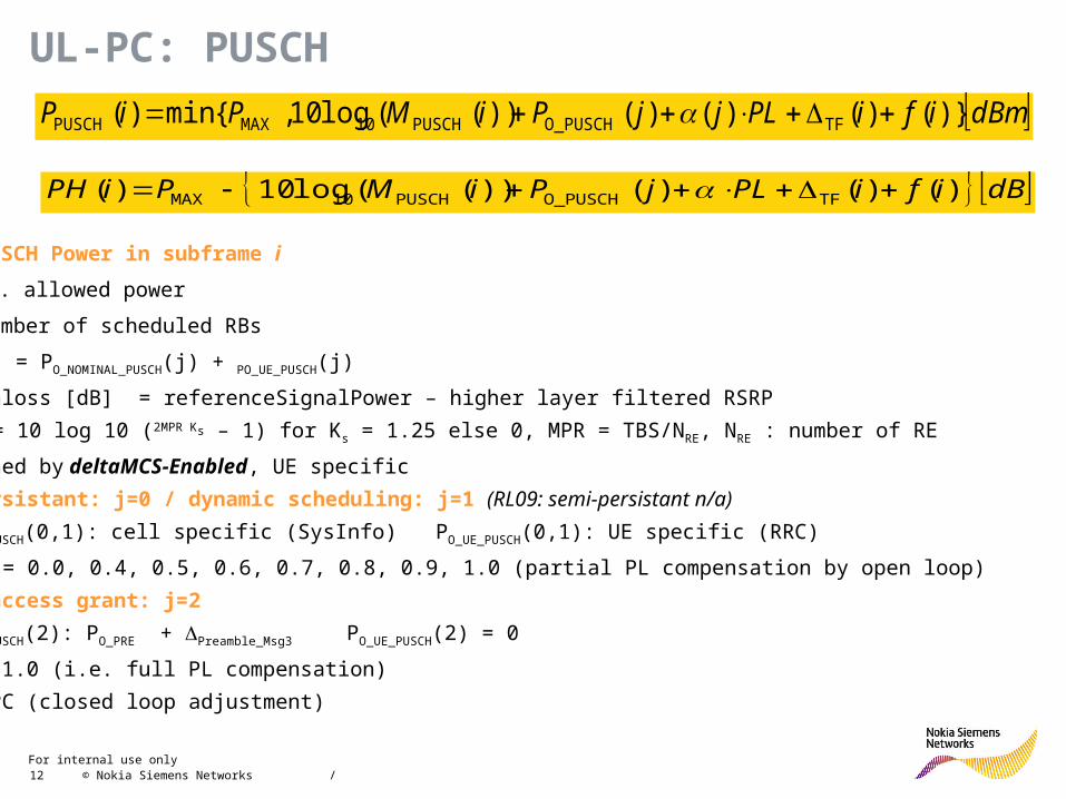
dBmifiPLjjPiMPiP )}()()()())((log10,{min)( TFO_PUSCHPUSCH10MAXPUSCH
PPUSCH: PUSCH Power in subframe i
Pmax: max. allowed power
MPUSCH: number of scheduled RBs
PO_PUSCH(j) = PO_NOMINAL_PUSCH(j) + PO_UE_PUSCH(j)
PL: pathloss [dB] = referenceSignalPower – higher layer filtered RSRP
TF (i) = 10 log 10 (2MPR Ks – 1) for Ks = 1.25 else 0, MPR = TBS/NRE, NRE : number of RE
Ks defined by deltaMCS-Enabled, UE specific
Semi-persistant: j=0 / dynamic scheduling: j=1 (RL09: semi-persistant n/a)
PO_NOMINAL_PUSCH(0,1): cell specific (SysInfo) PO_UE_PUSCH(0,1): UE specific (RRC)
(0,1) = 0.0, 0.4, 0.5, 0.6, 0.7, 0.8, 0.9, 1.0 (partial PL compensation by open loop)
Random access grant: j=2
PO_NOMINAL_PUSCH(2): PO_PRE + Preamble_Msg3 PO_UE_PUSCH(2) = 0
a (2) = 1.0 (i.e. full PL compensation)
f(i): TPC (closed loop adjustment)
dBifiPLjPiMPiPH )()()())((log10)( TFO_PUSCHPUSCH10MAX
For internal use only / 13 © Nokia Siemens Networks
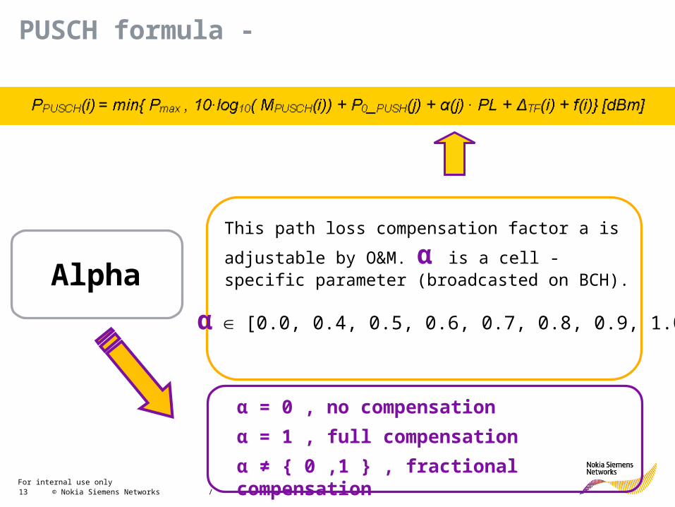
PUSCH formula -
Alpha
This path loss compensation factor a is adjustable by
O&M. α is a cell - specific parameter (broadcasted on BCH).
α [0.0, 0.4, 0.5, 0.6, 0.7, 0.8, 0.9, 1.0]
α = 0 , no compensation
α = 1 , full compensation
α ≠ { 0 ,1 } , fractional compensation

For internal use only / 14 © Nokia Siemens Networks
Module Contents
• Overview
• UL-PC: Overview
• UL-PC: PUSCH
• UL-PC: PUCCH
• UL-PC: SRS
• UL-PC: Control Scheme
• UL-PC: Closed Loop
• UL-PC: Parameters
• DL-PC: RL10
• DL-PC: PC on PDCCH

For internal use only / 15 © Nokia Siemens Networks
UL-PC: PUCCH
dBmigFnnhPLjPPiP HARQCQI )}()(),()(,min{)( F_PUCCH0_PUCCHMAXPUCCH
PPUCCH: PUCCH Power in subframe i
Pmax: max. allowed power
P0_PUCCH(j) = P0_NOMINAL_PUCCH(j) + P0_UE_PUCCH(j)
P0_NOMINAL_PUCCH : cell specific (SysInfo)
P0_UE_PUCCH : UE specific (RRC)
PL: pathloss [dB] = referenceSignalPower – higher layer filtered RSRP
F_PUCCH (F) : deltaFListPUCCH
PUCCH format 1, 1a, 1b: h(n) = 0
PUCCH format 2, 2a, 2b and :
h(n) = 0 if nCQI < 4
h(n) = 10log10 (nCQI/4) otherwise
(here: normal CP, for extented CP also nHARQ to be considered, n:number of information bits)
g(i): TPC (closed loop adjustment)
For internal use only / 16 © Nokia Siemens Networks
Module Contents
• Overview
• UL-PC: Overview
• UL-PC: PUSCH
• UL-PC: PUCCH
• UL-PC: SRS (not in RL10)
• UL-PC: Control Scheme
• UL-PC: Closed Loop
• UL-PC: Parameters
• DL-PC: RL10
• DL-PC: PC on PDCCH
For internal use only / 17 © Nokia Siemens Networks
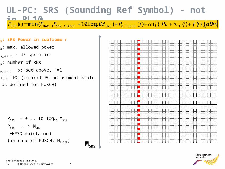
UL-PC: SRS (Sounding Ref Symbol) - not in RL10
PSRS: SRS Power in subframe i
Pmax: max. allowed power
PSRS_OFFSET : UE specific
MSRS: number of RBs
P0_PUSCH , : see above, j=1
f(i): TPC (current PC adjustment state
as defined for PUSCH)
dBmifiPLjjPMPPiP OFFSETSRS )}()()()()(log10,{min)( TFO_PUSCHSRS10_MAXSRS
PSRS = + .. 10 log10 MSRS
PSRS .. ~ MSRS
PSD maintained
(in case of PUSCH: MPUSCH)MSRS
For internal use only / 18 © Nokia Siemens Networks
Module Contents
• Overview
• UL-PC: Overview
• UL-PC: PUSCH
• UL-PC: PUCCH
• UL-PC: SRS
• UL-PC: Control Scheme
• UL-PC: Closed Loop
• UL-PC: Parameters
• DL-PC: RL10
• DL-PC: PC on PDCCH
For internal use only / 19 © Nokia Siemens Networks
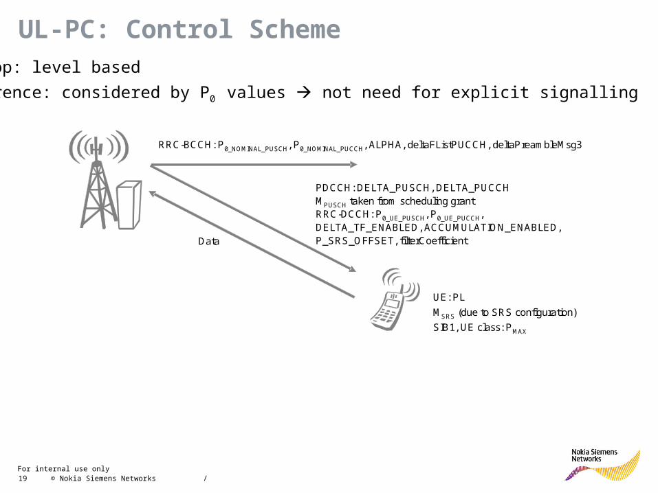
RRC-BCCH: P0_NOMINAL_PUSCH, P0_NOMINAL_PUCCH, ALPHA, deltaFListPUCCH, deltaPreambleMsg3
Data
UE: PL
MSRS (due to SRS configuration)
SIB1, UE class: PMAX
PDCCH: DELTA_PUSCH, DELTA_PUCCHMPUSCH taken from scheduling grantRRC-DCCH: P0_UE_PUSCH, P0_UE_PUCCH, DELTA_TF_ENABLED, ACCUMULATION_ENABLED, P_SRS_OFFSET, filterCoefficient
UL-PC: Control SchemeOpen loop: level based
Interference: considered by P0 values not need for explicit signalling
For internal use only / 20 © Nokia Siemens Networks
Module Contents
• Overview
• UL-PC: Overview
• UL-PC: PUSCH
• UL-PC: PUCCH
• UL-PC: SRS
• UL-PC: Control Scheme
• UL-PC: Closed Loop
• UL-PC: Parameters
• DL-PC: RL10
• DL-PC: PC on PDCCH

For internal use only / 21 © Nokia Siemens Networks
UL-PC: Closed loop - PUSCH and SRS (example)Closed loop adjustments:f(i) = f(i-1) + PUSCH (i - KPUSCH) i.e. recursive determination
or
f(i) = PUSCH (i - KPUSCH) i.e. absolute setting
where PUSCH is the signalled TPC in subframe i-KPUSCH
For FDD: KPUSCH = 4
whether the recursive or absolute method is used parameter Accumulation-enabled
Note, for RL09:
- Accumulation-enabled always “true”
- set “(-1,0,1,3) dB” supported; “(-1,1) dB” not supported
P (closed loop)
t

For internal use only / 22 © Nokia Siemens Networks
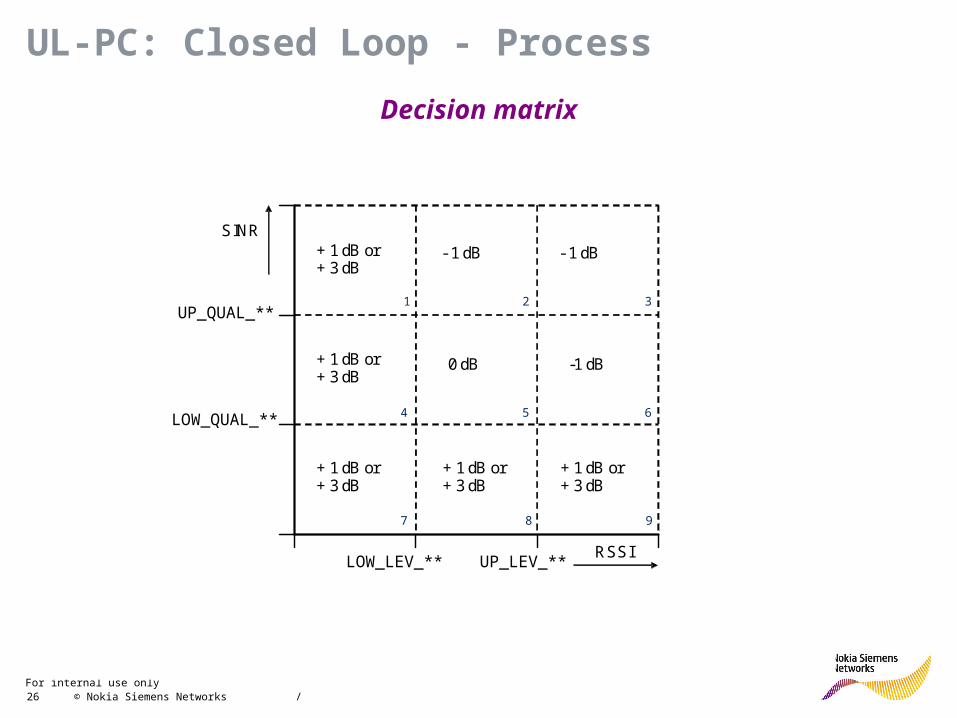
UL-PC: Closed Loop - Process
t
SIB/RRC parameters:P0_NOMINAL_PUSCH, P0_UE_PUSCH, P0_NOMINAL_PUCCH, P0_UE_PUCCH, ALPHA, deltaFListPUCCH, DELTA_TF_ENABLED, ACCUMULATION_ENABLED, deltaPreambleMsg3, P_SRS_OFFSET, filterCoefficient
Periodic reading of averaged level and averaged SINR value (time constant adjustable)
Weighting
Comparison with two-dimensional decision matrix. Calculation of DELTA_ PUSCH and DELTA_ PUCCH values for the UE
Commanding DELTA_PUSCH and DELTA_PUCCH values to the UE via PDCCH
Per UE measurements of• receive power of wanted signal• interference and noise
Calculation of average receive level per TTI.Calculation of SINR (two methods for I+N values)Transformation from Watt into dBm/dB domain.
Clipping using adjustable parameters
Transformation into TF independent format
Long term filtering/averaging of level and SINR using adjustable filter coefficients
time scale: TTI
time scale: filter output period (adjustable by O&M)
DELTA_TF_ENABLED, deltaFListPUCCH
ENABLE_CLPC
ENABLE_CLPC_PUSCH, ENABLE_CLPC_SRS; ENABLE_CLPC_PUCCH
SINR_MAX, SINR_MIN, RSSI_MAX, RSSI_MIN
WF_PUSCH_UE, WF_PUSCH_CELL, WF_SRS_UE, WF_SRS_CELL, WF_PUCCH_UE, WF_PUCCH_CELL
UP_LEV_PUSCH_SRS, LOW_LEV_PUSCH_SRS, UP_QUAL_PUSCH_SRS, LOW_QUAL_PUSCH_SRS, UP_LEV_PUCCH, LOW_LEV_PUCCH, UP_QUAL_PUCCH, LOW_QUAL_PUCCH, minCumDeltaPUSCH, maxCumDeltaPUSCH, minCumDeltaPUCCH, maxCumDeltaPUCCH
TAVG_PUSCH_SRS_CONT, TAVG_PUSCH_SRS_DISCONT, TAVG_PUCCH_CONT, TAVG_PUCCH_DISCONT
FILTER_OUTPUT_PERIOD
DELTA_PUSCH, DELTA_PUCCH

For internal use only / 23 © Nokia Siemens Networks
UL-PC: Closed Loop - Process
Averaged* received level per TTI per UE:
• RSSIPUSCH/UE
• RSSIPUCCH/UE
• RSSISRS/UE
relevant: PRBs allocated to the particular UE
Averaged* received SINR per TTI per UE:
Relevant for PUSCH and PUCCH: (I+N)UE and (I+N)cell
and for SRS: (I+N)cell
(I+N)cell : all potential PRBs
(I+N)UE : allocated PRBs to the particular UE
• SINRPUSCH/UE
• SINRPUSCH/cell
• SINRPUCCH/UE
• SINRPUCCH/cell
• SINRSRS/cell
Measurements and Averaging
* linear, but converted to dBm, dB for further deployment
Transformation in independent format
TF
PF_PUCCH
h(n)
PO_UE_PUSCH
P0_UE_PUCCH
Normalization applies to: UE and/or TF specific offsets get subtracted:
• PUSCH
• PUCCH
• SRS

For internal use only / 24 © Nokia Siemens Networks
UL-PC: Closed Loop - Process
Averaged received SINR per TTI per UE:
RSSI*** := min(max(RSSImin,RSSI***)RSSImax)
*** PUSCH/UE, PUSCH/cell, PUCCH/UE, PUCCH/cell, SRS/cell
Clipping
Weighting of MCS independent measurements
Averaged received level per TTI per UE:
RSSI*** := min(max(RSSImin,RSSI***)RSSImax)
*** PUSCH/UE, PUCCH/UE, SRS/UE
CELLSRSWFCELLPUSCHWFUEPUSCHWF
CELLSRSWFSINRCELLPUSCHWFSINRUEPUSCHWFSINRSINRC cellSRScellPUSCHUEPUSCH
SRSPUSCH ______
_______ ///
/
UESRSWFUEPUSCHWF
UESRSWFRSSIUEPUSCHWFRSSIRSSIC UESRSUEPUSCH
SRSPUSCH ____
_____ //
/
PUSCH and SRS - composite SINR and RSSI :
PUCCH - composite SINR and RSSI :
CELLPUCCHWFUEPUCCHWF
CELLPUCCHWFSINRUEPUCCHWFSINRSINRC cellPUCCHUEPUCCH
PUCCH ____
_____ //
UEPUCCHPUCCH RSSIRSSIC /_ Weighting factors WF_*** : range [1, 100]

For internal use only / 25 © Nokia Siemens Networks
Decision matrix for the
PUSCH/SRS component
of the CLPC algorithm
RSSIPUSCH/SRS,filtered
DELTA_PUSCH
value
SINRPUSCH/SRS,filtered
Decision matrix for the
PUCCH component of
the CLPC algorithm
RSSIPUCCH,filtered
DELTA_PUCCH
value
SINRPUCCH,filtered
UL-PC: Closed Loop - Process
Filtering
x: input (composite RSSI, SINR)
y: output (filtered RSSI, SINR)
n: step, max frequency = 1/TTI Initialization: y(0) := target RSSI/SINR
Low pass filter first order (exponential moving average) :
)()1()1()( nxcnycny c: filter coefficient
c = exp(-T/Tavg) i.e. impact = (1/e) at t = -Tavg
Example: T = 1ms, Tavg = 25 ms c = 0.96
For internal use only / 26 © Nokia Siemens Networks
LOW_QUAL_**
UP_QUAL_**
LOW_LEV_**
2 3
5 64
7
+ 1 dB or+ 3 dB
SINR
RSSI
-1 dB
- 1 dB - 1 dB
+ 1 dB or+ 3 dB
+ 1 dB or+ 3 dB
+ 1 dB or+ 3 dB
+ 1 dB or+ 3 dB
0 dB
8 9
UP_LEV_**
1
UL-PC: Closed Loop - Process
Decision matrix
For internal use only / 27 © Nokia Siemens Networks
Module Contents
• Overview
• UL-PC: Overview
• UL-PC: PUSCH
• UL-PC: PUCCH
• UL-PC: SRS
• UL-PC: Control Scheme
• UL-PC: Closed Loop
• UL-PC: Parameters and setting impacts
• DL-PC: RL10
• DL-PC: PC on PDCCH
For internal use only / 28 © Nokia Siemens Networks
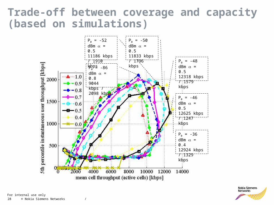
Trade-off between coverage and capacity (based on simulations)
P0 = -36 dBm = 0.412924 kbps / 1329 kbps
P0 = -86 dBm = 0.89044 kbps / 2098 kbps
P0 = -46 dBm = 0.512625 kbps / 1247 kbps
P0 = -48 dBm = 0.512318 kbps / 1579 kbps
P0 = -52 dBm = 0.511186 kbps / 1910 kbps
P0 = -50 dBm = 0.511833 kbps / 1796 kbps

For internal use only / 29 © Nokia Siemens Networks
UL-PC: ParametersName Object Abbreviation Range Description Default
Nominal Power For UE PUSCH Tx Power Calculation
LNCEL p0NomPusch -126...24 dB, step 1 dB
P0_NOMINAL_PUSCH(j=1)
UE specific PUSCH mean power for controllling the mean received SNR for user data in UE uplink power control algorithm
-100 dB
Nominal Power For UE PUCCH Tx Power Calculation
LNCEL p0NomPucch -127...-96 dB, step 1 dB
P0_NOMINAL_PUCCHControls mean received SNR for control data in UE uplink power control algorithm
-100 dB
Alpha LNCEL ulpcAlpha 0.0, 0.4, 0.5, 0.6, 0.7, 0.8, 0.9, 1.0
Used as a fractional path loss compensation factor: alpha. It controls received SNR variance (fairness) for user data and sounding reference symbol
1.0
Power Offset For UE PUCCH Tx Power Calculation
LNCEL p0UePucch -8...7 dB, step 1 dB
P0_UE_PUCCH: UE specific parameter, used to control mean received SNR for control data
0 dB
Power Offset For UE PUSCH Tx Power Calculation
LNCEL p0UePusch -8...7 dB, step 1 dB
P0_UE_PUSCH: UE specific PUSCH power offset for controlling the mean received SNR for user data in UE uplink power control algorithm
0 dB
TPC Step Size PUSCH
LNCEL tpcStepSize 0: TPC step size set (-1,0,1, 3)
1: TPC step size set (-1,1)
Selects between TPC step-size sets {-1; 0; 1; 3} and {-1; 1} to be used for power control command on PDCCH (single parameter for PUSCH and PUCCH). Note: in RL10 no support of (-1,1)
0
Enabled TB Size Impact To UE PUSCH Power Calculation
LNCEL deltaTfEnabled false, true deltaMCS-Enabled: enabling/disabling of transport format dependent offset on a per UE basis
false
For internal use only / 30 © Nokia Siemens Networks
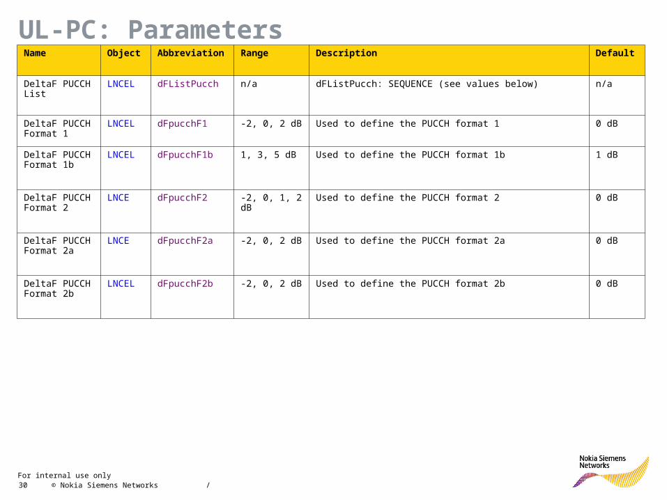
UL-PC: ParametersName Object Abbreviation Range Description Default
DeltaF PUCCH List
LNCEL dFListPucch n/a dFListPucch: SEQUENCE (see values below) n/a
DeltaF PUCCH Format 1
LNCEL dFpucchF1 -2, 0, 2 dB Used to define the PUCCH format 1 0 dB
DeltaF PUCCH Format 1b
LNCEL dFpucchF1b 1, 3, 5 dB Used to define the PUCCH format 1b 1 dB
DeltaF PUCCH Format 2
LNCE dFpucchF2 -2, 0, 1, 2 dB Used to define the PUCCH format 2 0 dB
DeltaF PUCCH Format 2a
LNCE dFpucchF2a -2, 0, 2 dB Used to define the PUCCH format 2a 0 dB
DeltaF PUCCH Format 2b
LNCEL dFpucchF2b -2, 0, 2 dB Used to define the PUCCH format 2b 0 dB
For internal use only / 31 © Nokia Siemens Networks
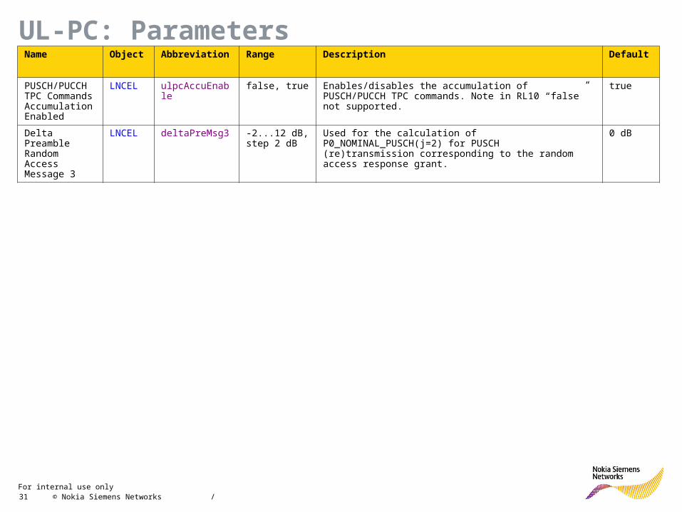
UL-PC: ParametersName Object Abbreviation Range Description Default
PUSCH/PUCCH TPC Commands Accumulation Enabled
LNCEL ulpcAccuEnable false, true Enables/disables the accumulation of PUSCH/PUCCH TPC commands. Note in RL10 “false” not supported.
true
Delta Preamble Random Access Message 3
LNCEL deltaPreMsg3 -2...12 dB, step 2 dB
Used for the calculation of P0_NOMINAL_PUSCH(j=2) for PUSCH (re)transmission corresponding to the random access response grant.
0 dB

For internal use only / 32 © Nokia Siemens Networks
UL-PC: ParametersName Object Abbreviation Range Description Default
Power Offset For SRS Transmission Power Calculation
LNCEL srsPwrOffset 0...15, step 1 Defines the power offset for SRS in UE uplink power control algorithm
Default=7
corresponding to 0 dB for DELTA_TF_ENABLED = 0
7
Filter Coefficient LNCEL filterCoeff fc0 (0), fc1 (1), fc2 (2), fc3 (3), fc4 (4), fc5 (5), fc6 (6), fc7 (7), fc8 (8), fc9 (9), fc11 (10), fc13 (11), fc15 (12), fc17 (13), fc19 (14)
Filter coefficient for RSRP measurements used to calculate path loss as specified in [3GPP-36.213. 5.1.1.1]. Value fc0 corresponds to k = 0, fc1 corresponds to k = 1, and so on.
fc4 (4)

For internal use only / 33 © Nokia Siemens Networks
Exercise 1: UL PC
Input:
• UE1 gets assigned 4 PRB for PUSCH
• d = 2 km
• closed loop f(i) = 0 dB
• S/I = 10 dB
• N = -174 dBm
• NFeNB= 2 dB
• Rx ant gain = 18 dBi
• Pmax = 23 dBm
• parameter values for UL PC: default
Note: PL[dB] for macro case may be used, 1 slope model, clutter = rural (open),
hBS = 30 m, hUE = 1.5 m, f = 2000 MHz:
L(d) [dB] = 105.27 + 35.22 log10(d[km])
Tasks:
- UL power for UE1 ?
- expected SINR ?
For internal use only / 34 © Nokia Siemens Networks
Module Contents
• Overview
• UL-PC: Overview
• UL-PC: PUSCH
• UL-PC: PUCCH
• UL-PC: SRS
• UL-PC: Control Scheme
• UL-PC: Closed Loop
• UL-PC: Parameters
• DL-PC: RL10
• DL-PC: PC on PDCCH
For internal use only / 35 © Nokia Siemens Networks
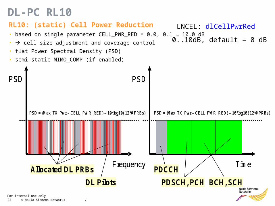
DL-PC RL10 RL10: (static) Cell Power Reduction • based on single parameter CELL_PWR_RED = 0.0, 0.1 … 10.0 dB
• cell size adjustment and coverage control
• flat Power Spectral Density (PSD)
• semi-static MIMO_COMP (if enabled)
PSD
Frequency
PSD = (Max_TX_Pwr – CELL_PWR_RED) – 10*log10( 12*# PRBs)
Allocated DL PRBs
DL Pilots
PSD
Time
PSD = (Max_TX_Pwr – CELL_PWR_RED) – 10*log10( 12*# PRBs)
PDCCH
BCH, SCHPDSCH, PCH
PSD
Frequency
PSD = (Max_TX_Pwr – CELL_PWR_RED) – 10*log10( 12*# PRBs)
Allocated DL PRBs
DL Pilots
PSD
Time
PSD = (Max_TX_Pwr – CELL_PWR_RED) – 10*log10( 12*# PRBs)
PDCCH
BCH, SCHPDSCH, PCH
LNCEL: dlCellPwrRed
0..10dB, default = 0 dB
For internal use only / 36 © Nokia Siemens Networks
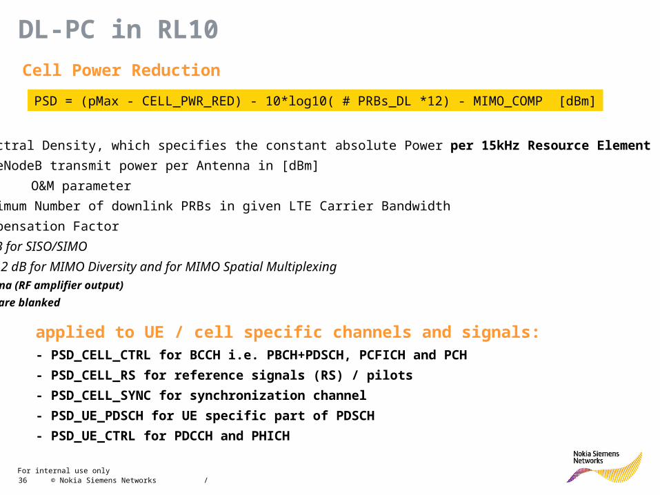
DL-PC in RL10
Cell Power Reduction
PSD = (pMax - CELL_PWR_RED) - 10*log10( # PRBs_DL *12) - MIMO_COMP [dBm]
PSD: Power Spectral Density, which specifies the constant absolute Power per 15kHz Resource Element (RE)
pMax: maximum eNodeB transmit power per Antenna in [dBm]
CELL_PWR_RED: O&M parameter
# PRBs_DL: maximum Number of downlink PRBs in given LTE Carrier Bandwidth
MIMO_COMP: Compensation Factor
MIMO_COMP = 0 dB for SISO/SIMO
MIMO_COMP = 0...12 dB for MIMO Diversity and for MIMO Spatial Multiplexing
- PSD given per antenna (RF amplifier output)
- PRBs not scheduled are blanked
applied to UE / cell specific channels and signals: - PSD_CELL_CTRL for BCCH i.e. PBCH+PDSCH, PCFICH and PCH
- PSD_CELL_RS for reference signals (RS) / pilots
- PSD_CELL_SYNC for synchronization channel
- PSD_UE_PDSCH for UE specific part of PDSCH
- PSD_UE_CTRL for PDCCH and PHICH

For internal use only / 37 © Nokia Siemens Networks
DL-PC RL09 - Parameters
Name Object Abbreviation Range Description Default
Cell Power Reduce
LNCEL dlCellPwrRed 0...10 dB,
step 0.1 dB
CELL_PWR_RED: Sets the power reduction from a antenna maximum Tx power
0 dB
MIMO Compensation
LNCEL dlpcMimoComp 0...10 dB,
step 0.1 dB
When TxDiv or 2x2 MIMO SM is used, gain applies in downlink. Parameter shall be set according to known gain (typically 3dB).
0 dB
For internal use only / 38 © Nokia Siemens Networks
Module Contents
• Overview
• UL-PC: Overview
• UL-PC: PUSCH
• UL-PC: PUCCH
• UL-PC: SRS
• UL-PC: Control Scheme
• UL-PC: Closed Loop
• UL-PC: Parameters
• DL-PC: RL10
• DL-PC: PC on PDCCH

For internal use only / 39 © Nokia Siemens Networks
Main target of DL-PC-CCH
• DL Power Control for PDCCH is an additional mechanism interacting with DL AMC for PDCCH in order to make the signaling as robust as possible
• DL-PC-CCH aims at 1% target BLER but cannot modify AGG assignments
• Main actions performed by DL-PC-CCH– Power reduction on CCEs with assigned AGG level higher than required (or equal)
– Power boosting on CCEs with assigned AGG level lower than required
– Equal power relocation among all scheduled CCEs
1-CCE8-CCE 2-CCE
4-CCE
• Macro cell case #1
• Uniform UE distribution Very good CCEs (CQI highly above 1% BLER target) Bad CCEs (AGG level too high to meet 1% BLER target) If still some power available, relocate equally among all CCEs
For internal use only / 40 © Nokia Siemens Networks
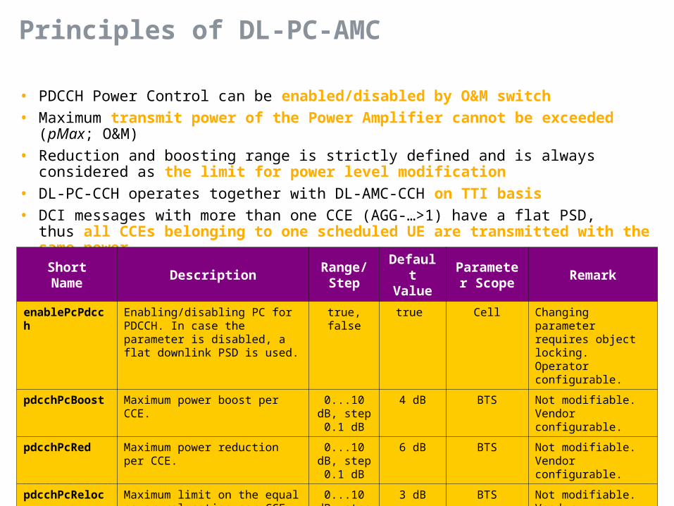
Principles of DL-PC-AMC
• PDCCH Power Control can be enabled/disabled by O&M switch
• Maximum transmit power of the Power Amplifier cannot be exceeded (pMax; O&M)
• Reduction and boosting range is strictly defined and is always considered as the limit for power level modification
• DL-PC-CCH operates together with DL-AMC-CCH on TTI basis
• DCI messages with more than one CCE (AGG-…>1) have a flat PSD,thus all CCEs belonging to one scheduled UE are transmitted with the same power
ShortName
DescriptionRange/
StepDefaultValue
Parameter Scope
Remark
enablePcPdcch Enabling/disabling PC for PDCCH. In case the parameter is disabled, a flat downlink PSD is used.
true, false true Cell Changing parameter requires object locking.Operator configurable.
pdcchPcBoost Maximum power boost per CCE. 0...10 dB, step 0.1
dB
4 dB BTS Not modifiable.Vendor configurable.
pdcchPcRed Maximum power reduction per CCE.
0...10 dB, step 0.1
dB
6 dB BTS Not modifiable.Vendor configurable.
pdcchPcReloc Maximum limit on the equal power relocation per CCE.
0...10 dB, step 0.1
dB
3 dB BTS Not modifiable.Vendor configurable.
For internal use only / 41 © Nokia Siemens Networks
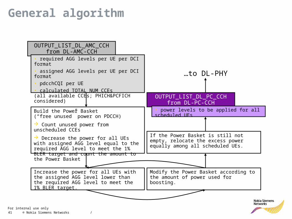
General algorithm
OUTPUT_LIST_DL_AMC_CCH from DL-AMC-CCH
• required AGG levels per UE per DCI format
• assigned AGG levels per UE per DCI format
• pdcchCQI per UE
• calculated TOTAL_NUM_CCEs(all available CCEs; PHICH&PCFICH considered)
Build the Power Basket(“free unused” power on PDCCH)
Count unused power from unscheduled CCEs
Decrease the power for all UEs with assigned AGG level equal to the required AGG level to meet the 1% BLER target and count the amount to the Power Basket
Increase the power for all UEs with the assigned AGG level lower than the required AGG level to meet the 1% BLER target.
Modify the Power Basket according to the amount of power used for boosting.
If the Power Basket is still not empty, relocate the excess power equally among all scheduled UEs.
OUTPUT_LIST_DL_PC_CCH from DL-PC-CCH
• power levels to be applied for all scheduled UEs
…to DL-PHY


