34
Inch Machine Screw Jack Inch Ball Screw Jack Inch Stainless Steel Machine Screw Jack M -Series Screw Jacks
Inch Machine Screw Jack
Inch Ball Screw Jack
Inch Stainless Steel Machine Screw Jack
M-SeriesScrew Jacks
M-Series - Inch Machine Screw Jack
Inch / Imperial Machine Screw Jacks2
1www.powerjacks.com
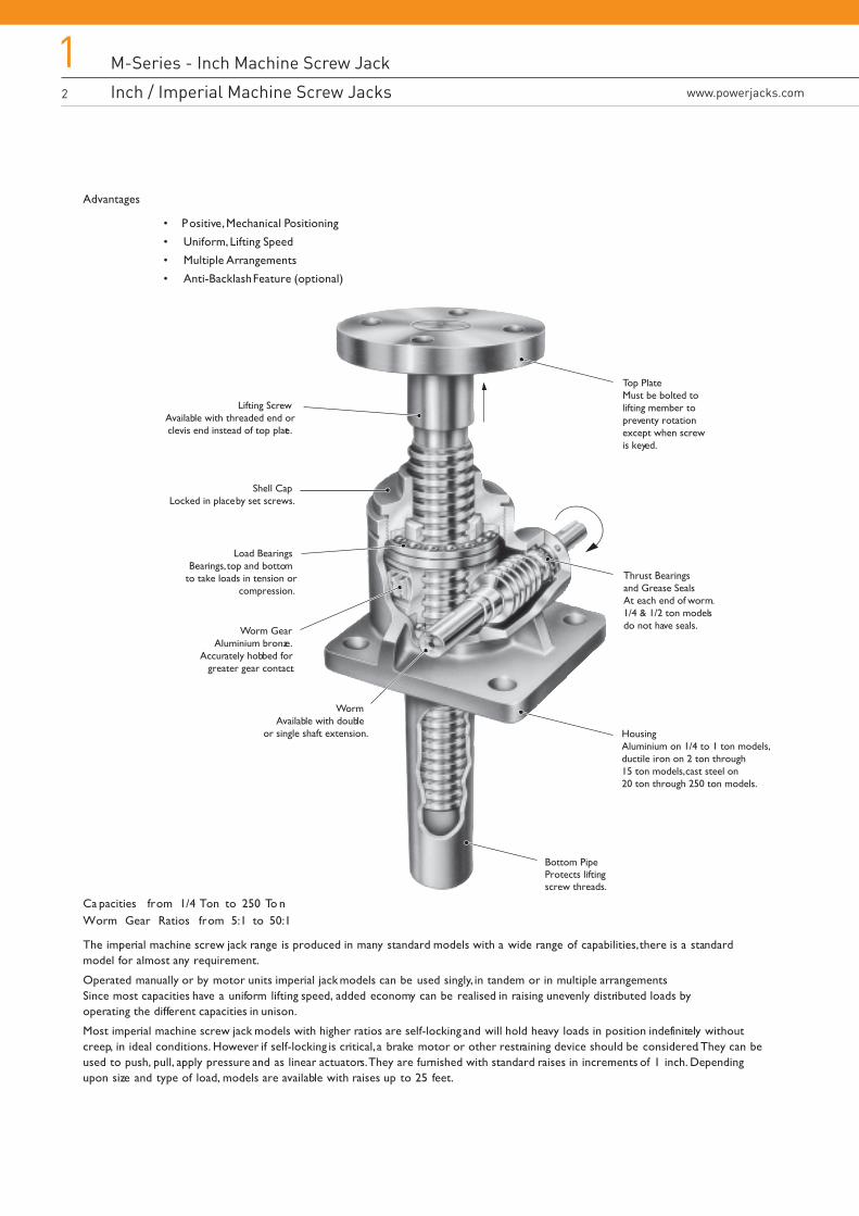
Advantages
• Positive, Mechanical Positioning
• Uniform, Lifting Speed
• Multiple Arrangements
• Anti-Backlash Feature (optional)
Ca pacities from 1/4 Ton to 250 To nWorm Gear Ratios from 5:1 to 50:1
The imperial machine screw jack range is produced in many standard models with a wide range of capabilities, there is a standardmodel for almost any requirement.
Operated manually or by motor units imperial jack models can be used singly, in tandem or in multiple arrangements Since most capacities have a uniform lifting speed, added economy can be realised in raising unevenly distributed loads byoperating the different capacities in unison.
Most imperial machine screw jack models with higher ratios are self-locking and will hold heavy loads in position indefinitely withoutcreep, in ideal conditions. However if self-locking is critical, a brake motor or other restraining device should be considered. They can beused to push, pull, apply pressure and as linear actuators. They are furnished with standard raises in increments of 1 inch. Dependingupon size and type of load, models are available with raises up to 25 feet.
Bottom Pipe Protects liftingscrew threads.
Shell CapLocked in place by set screws.
Lifting ScrewAvailable with threaded end orclevis end instead of top plate.
Load BearingsBearings, top and bottom
to take loads in tension orcompression.
Worm GearAluminium bronze.
Accurately hobbed for greater gear contact.
WormAvailable with double
or single shaft extension.
Thrust Bearingsand Grease SealsAt each end of worm.1/4 & 1/2 ton modelsdo not have seals.
Housing Aluminium on 1/4 to 1 ton models,ductile iron on 2 ton through15 ton models, cast steel on20 ton through 250 ton models.
Top PlateMust be bolted to lifting member to preventy rotation except when screw is keyed.
M-Series - Inch Machine Screw Jack
More Than 200 Standard Combinationswww.powerjacks.com
M-Series - Inch Machine Screw Jack
Inch / Imperial Machine Screw Jacks1
3
Features• Precise Positioning - Can be controlled accurately for positioning within thousandths of a millimetre.
• Self-Locking - Will normally hold loads in position without creeping when using the higher ratio units, as long as thescrew jack unit is not subject to vibration. If self-locking is critical a brake motor or other restraining device should beconsidered.
• Uniform Lifting Speed - Since many models have the same gear ratios, various capacities can be used in the sameapplication to lift unevenly distributed loads with uniform speed.
• Quick, Sure Operation - Designed and built to be positive acting, for accurate response to motive power.
Options• Anti-Backlash Option - Reduces vertical backlash between the screw and the worm gear nut to a practical
minimum for smooth, precise operation and minimum wear.
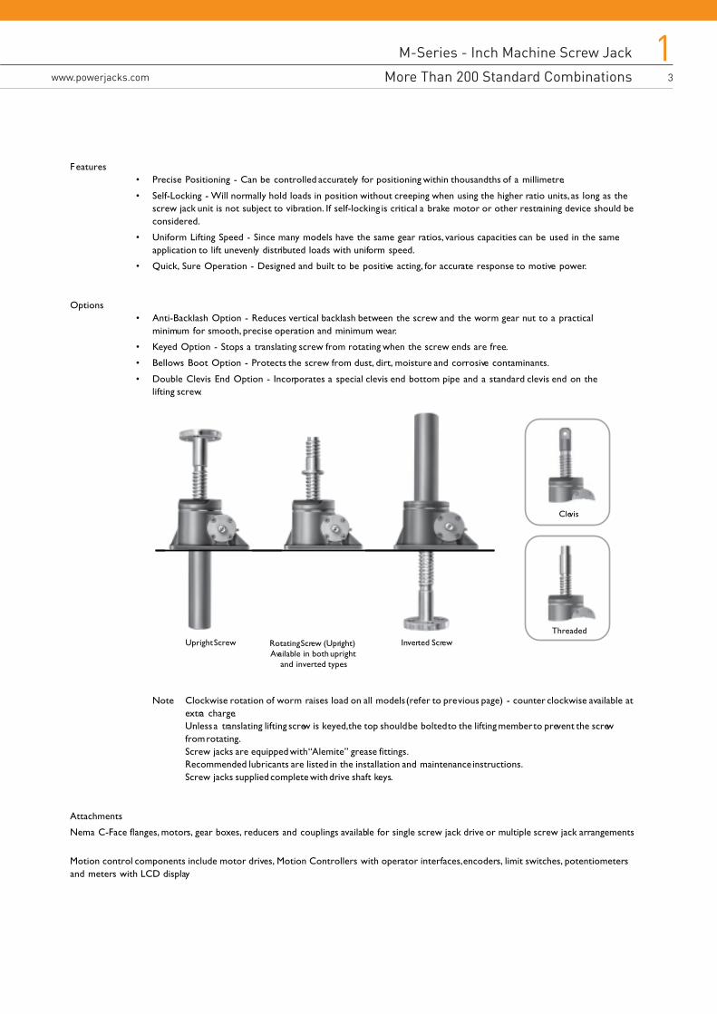
• Keyed Option - Stops a translating screw from rotating when the screw ends are free.
• Bellows Boot Option - Protects the screw from dust, dirt, moisture and corrosive contaminants.
• Double Clevis End Option - Incorporates a special clevis end bottom pipe and a standard clevis end on thelifting screw.
Note Clockwise rotation of worm raises load on all models (refer to previous page) - counter clockwise available atextra charge.Unless a translating lifting screw is keyed, the top should be bolted to the lifting member to prevent the screwfrom rotating.Screw jacks are equipped with “Alemite” grease fittings.Recommended lubricants are listed in the installation and maintenance instructions.Screw jacks supplied complete with drive shaft keys.
Attachments
Nema C-Face flanges, motors, gear boxes, reducers and couplings available for single screw jack drive or multiple screw jack arrangements
Motion control components include motor drives, Motion Controllers with operator interfaces, encoders, limit switches, potentiometersand meters with LCD display
Upright Screw Rotating Screw (Upright)Available in both upright
and inverted types
Inverted ScrewThreaded
Clevis
M-Series - Inch Machine Screw Jack
Performance of Standard M-Series Inch Machine Screw Jacks 4
1www.powerjacks.com
M2501
M2500
1
0.75
0.2
Acme
5:1
20:1
25
100
0.5
0.25
55
25
0.245
0.140
5
0.27
M1802 &
M9002M1801
&M9001
2
1
0.25
Acme
6:1
24:1
24
96
2
0.5
120
50
0.232
0.133
17
0.33
M2555
M2554
0.25
0.5
0.25
Acme
5:1
-
20
-
0.333
-
13
-
0.330
-
2.33
0.1
Upright
Inverted
Diameter
Pitch
Form
Standard
Optional
Standard
Optional
Standard
Optional
Standard
Optional
Standard
Optional
Capacity (Short Tons)
Model
Screw JackEfficiency
Weight with BaseRaise of 6” (lb)
Weight for eachAdditional I” Raise (lb)
M2625
M2624
0.5
0.625
0.125
Acme
5:1
-
40
-
0.333
-
21
-
0.200
-
2.33
0.1
M1815
M1814
15
2.25
0.5
Square
8:1
24:1
16
48
5
1.5
1430
820
0.202
0.129
66
1.5
M1805
M1804
5
1.5
0.375
Square
6:1
24:1
16
64
4
0.75
450
185
0.221
0.121
35
0.85
M1810
M1809
10
2
0.5
Square
8:1
24:1
16
48
5
1.5
950
490
0.220
0.140
52
1.4
M1825
M1824
M9035
M9034
M9075
M9074
25
3.375
0.666
Square
32:1
16
48
8
2.5
3360
1900
0.164
0.092
181
3.5
M1820
M1819
20
2.5
0.5
Square
8:1 10 2 3:1 10 2 3:1 10 2 3:1 10 2 3:1
24:1
16
48
5
1.5
2050
1170
0.188
0.120
93
2.6
M1850
M1849
50
4.5
0.666
Square
32:1
16
48
15
6
7500
4200
0.138
0.083
410
5.5
35
3.75
0.666
Acme
32:1
16
48
8
2.5
4000
2400
0.158
0.089
240
3.7
75
5
0.666
Square
32:1
16
48
15
6
12000
6600
0.124
0.075
650
6.5
M1899
M1898
100
6
0.75
Square
12:1
36:1
16
48
25
11
16000
8600
0.130
0.080
1200
9
M18150
M18149
150
7
1
Square
12:1
36:1
12
36
25
11
28100
15500
0.141
0.086
1350
12.6
M2250
M2249
250
9
1
Square
50:1
-
50
-
35
-
20000
-
0.080
-
2700
23
Lifting Screw
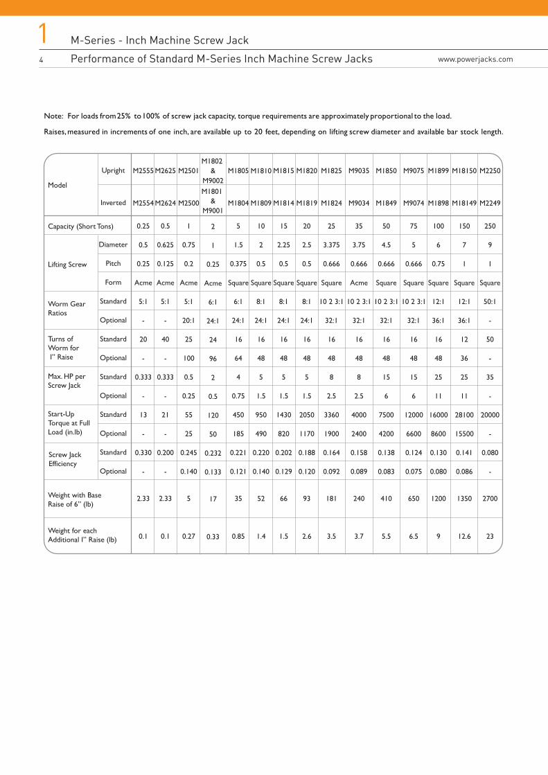
Note: For loads from 25% to 100% of screw jack capacity, torque requirements are approximately proportional to the load.
Raises, measured in increments of one inch, are available up to 20 feet, depending on lifting screw diameter and available bar stock length.
Worm GearRatios
Turns ofWorm for I” Raise
Start-UpTorque at FullLoad (in.lb)
Max. HP perScrew Jack
M-Series - Inch Machine Screw Jack
Translating Screw Jack Dimensions
M-Series - Inch Machine Screw Jack
Performance of Standard M-Series Inch Machine Screw Jacks www.powerjacks.com
15
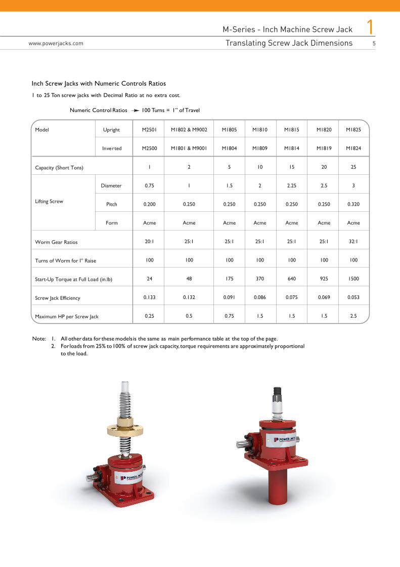
Inch Screw Jacks with Numeric Controls Ratios
1 to 25 Ton screw jacks with Decimal Ratio at no extra cost.
Numeric Control Ratios 100 Turns = 1” of Travel
Note: 1. All other data for these models is the same as main performance table at the top of the page.2. For loads from 25% to 100% of screw jack capacity, torque requirements are approximately proportional
to the load.
Capacity (Short Tons)
Screw Jack Efficiency
Upright
Inverted
Diameter
Pitch
Form
Model M2501
M2500
1
0.75
0.200
Acme
20:1
100
24
0.133
0.25
M1805
M1804
5
1.5
0.250
Acme
25:1
100
175
0.091
0.75
M1810
M1809
10
2
0.250
Acme
25:1
100
370
0.086
1.5
M1815
M1814
15
2.25
0.250
Acme
25:1
100
640
0.075
1.5
M1820
M1819
20
2.5
0.250
Acme
25:1
100
925
0.069
1.5
M1825
M1824
25
3
0.320
Acme
32:1
100
1500
0.053
2.5
M1802 & M9002
M1801 & M9001
2
1
0.250
Acme
25:1
100
48
0.132
0.5
Lifting Screw
Worm Gear Ratios
Turns of Worm for I” Raise
Start-Up Torque at Full Load (in.lb)
Maximum HP per Screw Jack
M-Series - Inch Machine Screw Jack
Translating Screw Jack Dimensions6
1www.powerjacks.com
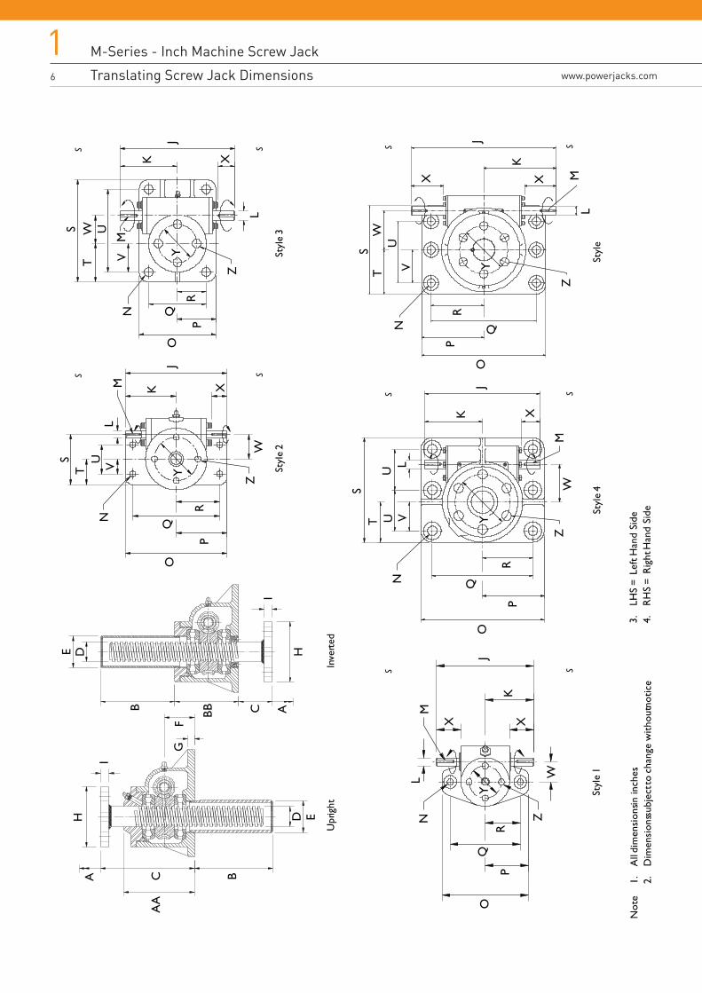
Not
e1.
All
dim
ensi
ons in
inch
es.
2.D
imen
sion
s sub
ject
to c
hang
e w
ithou
t not
ice.
Upr
ight
A
Inve
rted
CA
A
B
D E
GF
I
HE D
B BB C AH
ISt
yle
2St
yle
3
ST
U VN
O
PR
Q
ZW
XK
J
LM
ST
U
VN
O
PR
Q
Z
W
XK
J
L
M
Styl
e 1
N
O
PR
Q
ZW
XK
J
LM
YY
X
Y
Styl
e 4S
TU
VN
O
PR
Q
ZW
XK
J
M
Y
LU
ST
X
VN
O
PR
Q
Z
W
X
K
J
M
Y
L
U
Styl
e
3.LH
S =
Left
Han
d Si
de4.
RH
S =
Rig
ht H
and
Side
M-Series - Inch Machine Screw Jack
Translating Screw Jack Dimensions
M-Series - Inch Machine Screw Jack
Translating Screw Jack Dimensions www.powerjacks.com
17
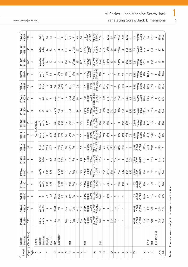
Mod
el
Styl
e
Upr
ight
Cap
acity
(Sh
ort
Ton
s)In
vert
ed
Upr
ight
Inve
rted
Upr
ight
Inve
rted
Dia
met
er
A B C D E F G H I J K L M N O P Q R S T U V W X Y Z A-A B-B
No
of H
oles
M25
55M
2554
0.25 1 0.5 1
5 /16
21/4
5 /16
41/2
21/4
9 /32 4 2 31/4
15/8
11/8
1.5
9 /32 4 23/8
23/8
M26
25M
2624
M25
01M
2500
M18
02M
1801
M90
02M
9001
M18
05M
1804
M18
10M
1809
M18
15M
1814
M18
20M
1819
M18
25M
1824
M90
35M
9034
M18
50M
1849
M90
75M
9074
M18
99M
1898
M18
150
M18
149
M22
50M
2249
0.5 1
0.62
5
15 /
16
21/4
5 /16
41/2
21/4
9 /32 4 2 31/4
15/8
11/8
1.5
9 /32 4 23/8
23/8
1 1 0.75 1.5
3 /8
31/2
3 /8 6 3
13/3
2
5 21/2 4 2
17/1
6
2.5
7 /16 4 31/4
31/4
2 2 1 1.75 1 /2
41/4
7 /16 7 3.5
13/3
2
7 3.5 6 3 31/2
13/4 2 1 11/8 3
13/3
2
441
/16
33/4
2 3 1 1.75 1 /2
41/4
7 /16 7 3.5
13/3
2
41/8
21/1
6
31/8
19/1
6
61/4
2.42
51/4
1.93
11/8 3
13/3
2
441
/16
33/4
5 3 1.5
2.25 1 /2
41/2
5 /8 9 4.5
11/1
6
6 3 41/2
21/4 8 3 61/2
2.25
111 /
32
311
/16
4 51/4
43/4
10 3 2 2.25 1 /2
53/4
3 /4
11 5.5
13/1
6
7.5
33/4
53/4
27/8
83/4
27/8 7 2
123 /
32
4.13
13/1
6
4 55/8 5
15 3 2.25
2.75 5 /8
53/4
3 /4
11 5.5
13/1
673
/437
/8 6 3 91/4
33/8
71/2
2.5
123 /
32
4.13
13/1
6
465
/16
51/2
20 3 2.5
3.25 3 /4
53/4
3 /4
11 5.5
11/8
81/4
41/8 6 3 11 41/8
83/4 3 13/8
4.13
13/1
6
4 71/8
71/8
25 3
3.37
5
4 1 81/2 1 14 7 13/8
101 /
4
51/8
71/2
33/4
133 /
4
51/8
11 3.75
23/1
6
611
/16
4 87/8
87/8
35 3 3.75 4 11/4
101 /
2
15/1
6
14 7 15/8
10.2
551
/871
/233
/415
1 /2
6 12.5
4.5
23/1
6
7.75
15/8 4 87/8
87/8
50 2 4.5
4.75
11/4
111 /
4
11/4
22 11 17/8
193 /
4
97/8
16 8 93/4
47/8 6 3
45/1
6
8.75
13/8 4
107 /
8
107 /
8
75 2 5 5.5
13/8
111 /
4
13/8
24 12 21/8
14 7 10 5 23 9.5
19 7.5
41/8
10.2
51.
5 613
9 /16
139 /
16
100 4 6 6 11/2
1421
5 /16
23 11.5
17/8
241 /
2
121 /
4
20 10 203 /
4
8 81/8
5.75
37/1
6
11 17/8 6 17 17
150 4 7 6 11/2
1421
5 /16
23 11.5
17/8
24.5
121 /
4
20 10 203 /
4
8 81/8
5.75
41/4
11 17/8 6 17 17
250 5 9 9 21/2
2431
5 /16
48 24 23/4
41 201 /
2
35 17.5
291 /
2
14.7
520
1 /2
11 101 /
2
16 23/4 6
231 /
8
231 /
8
RA
ISE D
A+
3 /4
A+
3 /4
7 /8
7 /8
15/1
612
1 /32
121 /
3223
/827
/827
/831
/241
/241
/259
/16
65/8
78
11
0.37
5+0
.000
-0.0
02
0.37
5+0
.000
-0.0
02
0.50
0+0
.000
-0.0
02
0.50
0+0
.000
-0.0
02
0.50
0+0
.000
-0.0
02
0.75
+0.0
00-0
.002
1+0
.000
-0.0
02
1+0
.000
-0.0
02
1+0
.000
-0.0
02
1.37
5+0
.000
-0.0
02
1.37
5+0
.000
-0.0
02
1.5
+0.0
00-0
.002
1.75
+0.0
00-0
.002
1.75
+0.0
00-0
.002
1.87
5+0
.000
-0.0
02
3+0
.000
-0.0
02
0.93
8+0
.003
-0.0
00
0.93
8+0
.003
-0.0
00
1.25
+0.0
03-0
.003
1.70
3+0
.001
-0.0
01
1.70
3+0
.001
-0.0
01
2.18
8+0
.002
-0.0
00
2.59
8+0
.003
-0.0
00
2.59
8+0
.003
-0.0
00
2.59
8+0
.003
-0.0
00
3.75
+0.0
05-0
.000
3.75
+0.0
05-0
.000
5.31
3+0
.003
-0.0
00
5.31
3+0
.003
-0.0
00
7.5
+0.0
03-0
.000
7.5
+0.0
03-0
.000
13+0
.005
-0.0
00
1 /8
x 1 /
163 /
4 LN
G1 /
8 x
1 /16
3 /4
LNG
1 /8
x 1 /
16 1
LN
G1 /
8 x
1 /16
1 L
NG
1 /8
x 1 /
16 1
LN
G3 /
16 x
3/3
2 1
1 /4
LNG
1 /4
x 1 /
8 1
1 /2
LNG
1 /4
x 1 /
8 1
1 /2
LNG
1 /4
x 1 /
8 1
1 /2
LNG
5 /16
x 5
/32
2 L
NG
3 /8
x 3 /
16 2
1 /4
LNG
3 /8
x 3 /
16 2
1 /4
LNG
1 /2
x 1 /
4 3
LN
G1 /
2 x
1 /4
3 L
NG
3 /4
x 3 /
8 5
LN
G0.3
13 x
0.15
62
LNG
4 2
A+
3 /4
A+
3 /4
A-1
/8A
-1/8
A-1
/4A
A-1
/8A
-1/8
A A4 2
4.5
1.25
5.25
1.75
5.25
1.75
7 2.5
A-1
/8A
-1/8
A-1
/8A
-1/8
A-1
/2A
-1/2
A AA A-1
7.25
2.75
8 2.75
9.25 3
11 312 4
A-3
/8A
-3/8
13 3.5
A-1
/2A
-1/2
16.5
5.5
A+/
-1/4
A+/
-1/4
24 12
A-1
/2A
-1/2
24 12
A-2
A+
1 /2
30 12
AS
REQ
UIR
ED
--
- --
-- -
--
--
-
Not
eD
imen
sion
s are
sub
ject
to c
hang
e w
ithou
t not
ice .
M-Series - Inch Machine Screw Jack
Rotating Screw Jack Dimensions8
1www.powerjacks.com
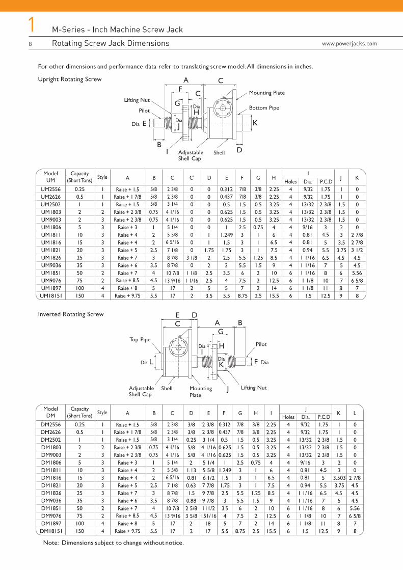
For other dimensions and performance data refer to translating screw model. All dimensions in inches.
Upright Rotating Screw
Inverted Rotating Screw
Note: Dimensions subject to change without notice.
ModelUM
UM2556UM2626UM2502UM1803UM9003UM1806UM1811UM1816UM1821UM1826UM9036UM1851UM9076UM1897UM18151
Capacity(Short Tons)
0.250.5122510152025355075100150
Style
Raise + 1.5 5/85/8
2 3/8 7/87/8
3/8 9/329/323/8
6
2 3/83 1/4
5 1/45 5/86 5/167 1/88 7/8 3 1/88 7/810 7/813 9/16
1 1/81 1/16
4 1/164 1/16
5/8
A B D E F GHoles Dia. P.C.D
H J KI
Raise + 1 7/8Raise + 1.5
Raise + 2 3/8Raise + 2 3/8
Raise + 3Raise + 4Raise + 4Raise + 5Raise + 7
Raise + 8.5Raise + 8
Raise + 9.75
Raise + 7Raise + 6
111233333332244
0.750.75122
44.5
2.53
3.5
55.5
C
1717
000000 4
66.5
8.59
14
11
1.7522
2.52.55
3.5
0.3120.4370.5
0.6250.625
1
1.51.249
1.752.53
3.5
54
5.5 8.75
1.51.51.52.5333
5.55.5
7.57
0.50.50.50.75
111
1.251.5222
2.5
2.252.253.253.253.25
7.5
1012.5
15.5
444
44
6
44444
4
66
6
9/160.810.81
1 1/161 1/16
1 1/8
13/3213/3213/32
2 3/82 3/82 3/8
2 7/82 7/83 1/20.94
1 1/161 1/8
1.5
1.751.75
3
55.56.5 4.5 4.5
4.55.566 5/8
4.5
781011
12.5
6
89
11
1.51.51.523
3.53.75
5
7
000000
78
000000000
0
22
C'
ModelDM
DM2556DM2626DM2502DM1803DM9003DM1806DM1811DM1816DM1821DM1826DM9036DM1851DM9076DM1897DM18151
Capacity(Short Tons)
0.250.5122510152025355075100150
Style
Raise + 1.5 5/85/8
2 3/8 0.3120.437
7/8 9/329/327/8
3.5
2 3/83 1/4
5 1/45 5/86 5/167 1/88 7/88 7/810 7/813 9/16
4 1/164 1/16
5/8
A B D E F GHoles Dia. P.C.D
H K LJ
Raise + 1 7/8Raise + 1.5
Raise + 2 3/8Raise + 2 3/8
Raise + 3Raise + 4Raise + 4Raise + 5Raise + 7
Raise + 8.5Raise + 8
Raise + 9.75
Raise + 7Raise + 6
111233333332244
0.750.75122
44.5
2.53
3.5
55.5
C
1717
3/83/80.255/85/82 0.75
11
1.251.5
2
1.130.810.631.50.882 5/83 5/8
22
2 3/82 3/83 1/44 1/164 1/165 1/4
6 1/25 5/8
7 7/89 7/89 7/8111/2
18151/16
17 5.5
0.50.6250.625
11.2491.51.752.53
45
1.51.51.52.5333
5.55.56
7.57
8.75
3/83/80.50.50.5
1
22
2.5
I
46
6.5
8.59
14
2.252.253.253.253.25
7.5
1012.5
15.5
444
44
6
44444
4
66
6
9/160.810.81
1 1/161 1/16
1 1/8
13/3213/3213/32
2 3/82 3/82 3/8
02 7/84.50.94
1 1/161 1/8
1.5
1.751.75
3
55.56.5 4.5 4.5
4.55.566 5/8
4.5
781011
12.5
6
89
11
1.51.51.523
3.5033.75
5
7
000000
78
DiaJ
Pilot
BDShellAdjustable
Shell Cap
Dia
Lifting Nut
Lifting Nut
E
A CF
G DiaH
Mounting Plate
Bottom Pipe
MountingPlate
K
Pilot
BD
ShellAdjustableShell Cap
F Dia
AG
DiaK
Top Pipe
Dia L
J
DiaI
H
EC
I
M-Series - Inch Machine Screw Jack
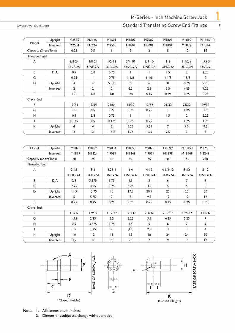
Standard Translating Screw End Fittingswww.powerjacks.com
19
M-Series - Inch Machine Screw Jack
Rotating Screw Jack Dimensions
Note 1. All dimensions in inches.2. Dimensions subject to change without notice.
B
A
E
C
D(Closed Height)
BASE
OF
SCR
EW JA
CK
GI I
FH
K(Closed Height)
BASE
OF
SCR
EW JA
CK
M2555
M2554
0.25
3/8-24
UNF-2A
0.5
0.75
4
2
1/8
13/64
3/8
0.5
0.375
4
2
Upright
Inverted
DIA
Upright
Inverted
Upright
Inverted
Model
A
B
C
D
E
Clevis End
F
G
H
I
K
Capacity (Short Tons)
M2625
M2624
0.5
3/8-24
UNF-2A
5/8
1
4
2
1/8
17/64
0.5
5/8
0.5
4
2
M2501
M2500
1
1/2-13
UNC-2A
0.75
0.75
5 3/8
2
1/8
21/64
0.5
0.75
0.375
5
1 5/8
M1802
M1801
2
3/4-10
UNC-2A
1
1 1/8
6
2.5
1/8
13/32
0.75
1
0.75
5.25
1.75
M9002
M9001
2
3/4-10
UNC-2A
1
1 1/8
6
2.5
0.19
13/32
0.75
1
0.75
5.25
1.75
M1805
M1804
5
1-8
UNC-2A
1.5
1 1/8
8
3.5
0.19
21/32
1
1.5
1
7
2.5
M1810
M1809
10
1 1/2-6
UNC-2A
2
1 5/8
8.75
4.25
0.25
25/32
1.25
2
1.25
7.5
3
M1815
M1814
15
1.75-5
UNC-2
2.25
2
9.75
4.25
0.25
29/32
1.5
2.25
1.25
8.5
3
M1820
M1819
20
2-4.5
UNC-2A
2.5
2.25
11.5
5
0.25
1 1/32
1.75
2.5
1.5
10
3.5
Upright
Inverted
DIA
Upright
Inverted
Upright
Inverted
Model
A
B
C
D
E
Clevis End
F
G
H
I
K
Capacity (Short Tons)
M1825
M1824
M9034
M9034
25
3-4
UNC-2A
3.375
3.25
13.75
5.75
0.25
1 9/32
2.25
3.375
1.75
12
4
35
3.25-4
UNC-2A
3.75
3.75
15
7
0.25
1 17/32
2.5
3.75
2
13
5
M9075
M9074
M1850
M1849
50
4-4
UNC-2A
4.5
4.25
17.5
8
0.25
1 25/32
3.25
4.5
2.5
15
5.5
75
4-12
UNC-2A
5
4.5
20.5
9.5
0.25
2 1/32
3.5
5
2.5
18
7
M1899
M1898
100
4 1/2-12
UNC-2A
6
5
25
12
0.25
2 17/32
4.25
6
3
24
9
M18150
M18149
150
5-12
UNC-2A
7
5
25
12
0.25
2 25/32
5.25
7
3
24
9
M2250
M2249
250
8-12
UNC-2A
9
6
30
12
0.25
3 17/32
7
9
4
30
12
Threaded End
Threaded End
M-Series - Inch Machine Screw Jack
Double Clevis Screw Jacks10
1www.powerjacks.com
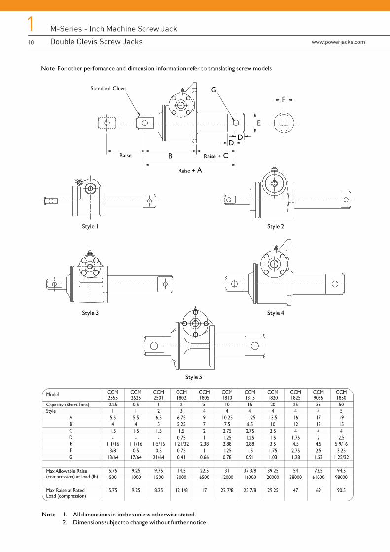
Note For other performance and dimension information refer to translating screw models.
Note 1. All dimensions in inches unless otherwise stated.2. Dimensions subject to change without further notice.
Model CCM2555
CCM2625
CCM2501
CCM1802
CCM1805
CCM1810
CCM1815
CCM1820
CCM1825
CCM9035
CCM1850
0.251
5.54
1.5-
1 1/163/8
13/64
5.75500
5.75
ABCDEFG
Capacity (Short Tons)Style
Max Allowable Raise(compression) at load (lb)
Max Raise at RatedLoad (compression)
0.51
5.54
1.5-
1 1/160.5
17/64
9.251000
9.25
12
6.55
1.5-
1 5/160.5
21/64
9.751500
8.25
23
6.755.251.50.75
1 21/320.750.41
14.53000
12 1/8
549721
2.381
0.66
22.56500
17
104
10.257.52.751.252.881.250.78
3112000
22 7/8
154
11.258.52.751.252.881.50.91
37 3/816000
25 7/8
204
13.5103.51.53.51.751.03
39.2520000
29.25
25416124
1.754.52.751.28
5438000
47
354171342
4.52.51.53
73.561000
69
50519154
2.55 9/163.25
1 25/32
94.598000
90.5
Style 1
B
Style 2
Style 3 Style 4
Style 5
Raise
Raise + A
Raise + C
DD
E
FGStandard Clevis
M-Series - Inch Machine Screw Jack
Anti-Backlash Screw Jackswww.powerjacks.com
111
M-Series - Inch Machine Screw Jack
Double Clevis Screw Jacks
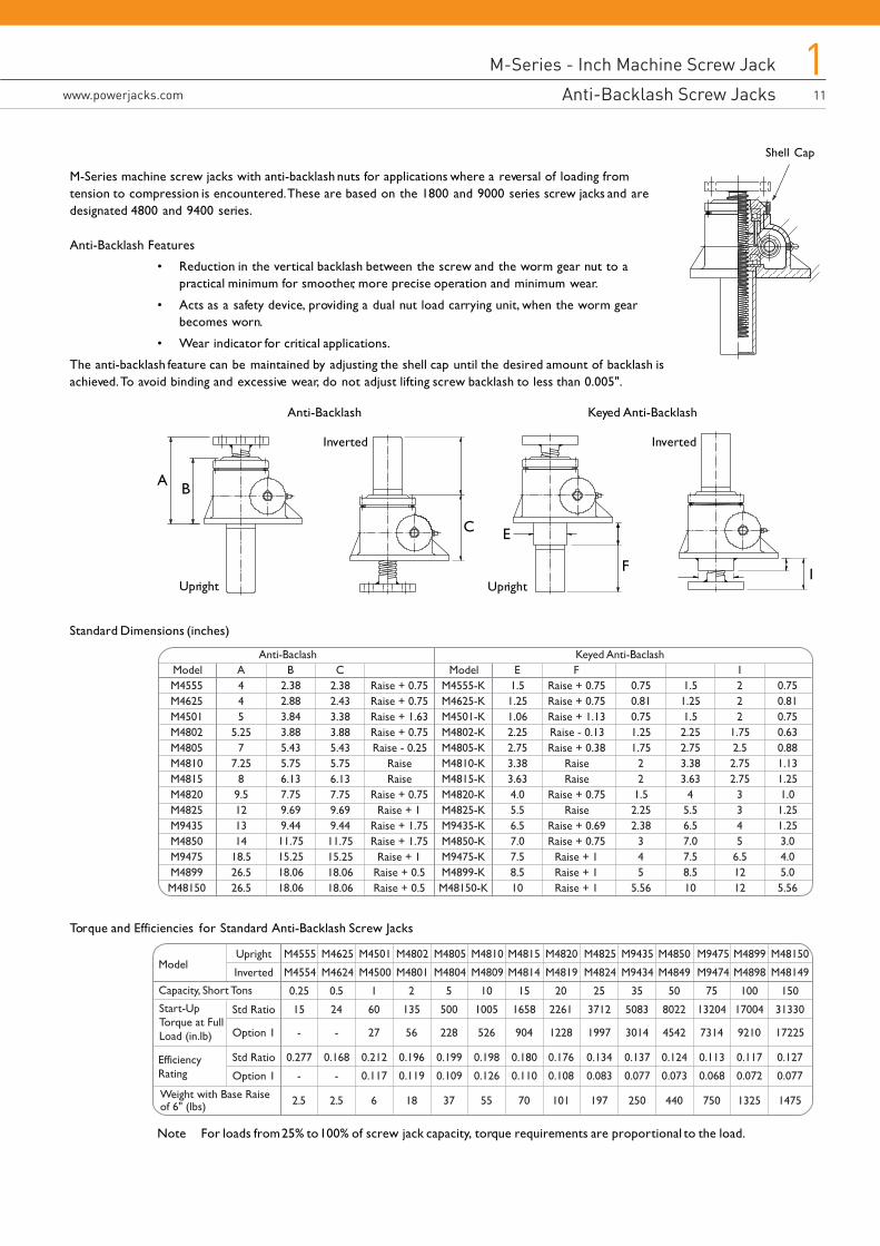
M-Series machine screw jacks with anti-backlash nuts for applications where a reversal of loading fromtension to compression is encountered. These are based on the 1800 and 9000 series screw jacks and aredesignated 4800 and 9400 series.
Anti-Backlash Features
• Reduction in the vertical backlash between the screw and the worm gear nut to apractical minimum for smoother, more precise operation and minimum wear.
• Acts as a safety device, providing a dual nut load carrying unit, when the worm gearbecomes worn.
• Wear indicator for critical applications.
The anti-backlash feature can be maintained by adjusting the shell cap until the desired amount of backlash isachieved. To avoid binding and excessive wear, do not adjust lifting screw backlash to less than 0.005".
Standard Dimensions (inches)
Torque and Efficiencies for Standard Anti-Backlash Screw Jacks
Note For loads from 25% to 100% of screw jack capacity, torque requirements are proportional to the load.
Model
Capacity, Short Tons
Start-Up Torque at Full Load (in.lb)
M4555
M4554
0.25
15
-
0.277
-
2.5
Upright
Inverted
Std Ratio
Option 1
Std Ratio
Option 1
M4625
M4624
0.5
24
-
0.168
-
2.5
M4501
M4500
1
60
27
0.212
0.117
6
M4802
M4801
2
135
56
0.196
0.119
18
M4805
M4804
5
500
228
0.199
0.109
37
M4810
M4809
10
1005
526
0.198
0.126
55
M4815
M4814
15
1658
904
0.180
0.110
70
M4825
M4824
25
3712
1997
0.134
0.083
197
M9435
M9434
35
5083
3014
0.137
0.077
250
M4850
M4849
50
8022
4542
0.124
0.073
440
M9475
M9474
75
13204
7314
0.113
0.068
750
M4899
M4898
100
17004
9210
0.117
0.072
1325
M48150
M48149
150
31330
17225
0.127
0.077
1475
M4820
M4819
20
2261
1228
0.176
0.108
101
EfficiencyRating
Weight with Base Raiseof 6" (lbs)
ModelM4555M4625M4501M4802M4805M4810M4815M4820M4825M9435M4850M9475M4899M48150
A445
5.257
7.258
9.5121314
18.526.526.5
ModelM4555-KM4625-KM4501-KM4802-KM4805-KM4810-KM4815-KM4820-KM4825-KM9435-KM4850-KM9475-KM4899-KM48150-K
E1.51.251.062.252.753.383.634.05.56.57.07.58.510
0.750.810.751.251.75
22
1.52.252.38
345
5.56
1.51.251.52.252.753.383.63
45.56.57.07.58.510
I222
1.752.52.752.75
3345
6.51212
0.750.810.750.630.881.131.251.01.251.253.04.05.05.56
B2.382.883.843.885.435.756.137.759.699.4411.7515.2518.0618.06
Keyed C
2.382.433.383.885.435.756.137.759.699.4411.7515.2518.0618.06
Raise + 0.75Raise + 0.75Raise + 1.63Raise + 0.75Raise - 0.25
RaiseRaise
Raise + 0.75Raise + 1
Raise + 1.75Raise + 1.75
Raise + 1Raise + 0.5Raise + 0.5
FRaise + 0.75Raise + 0.75Raise + 1.13Raise - 0.13Raise + 0.38
RaiseRaise
Raise + 0.75Raise
Raise + 0.69Raise + 0.75
Raise + 1Raise + 1Raise + 1
Shell Cap
Upright
Inverted
Upright
Inverted
B
C
A
F
E
I
Anti-Backlash Keyed Anti-Backlash
M-Series - Inch Machine Screw Jack
Bellows Boots Screw Protection12
1www.powerjacks.com
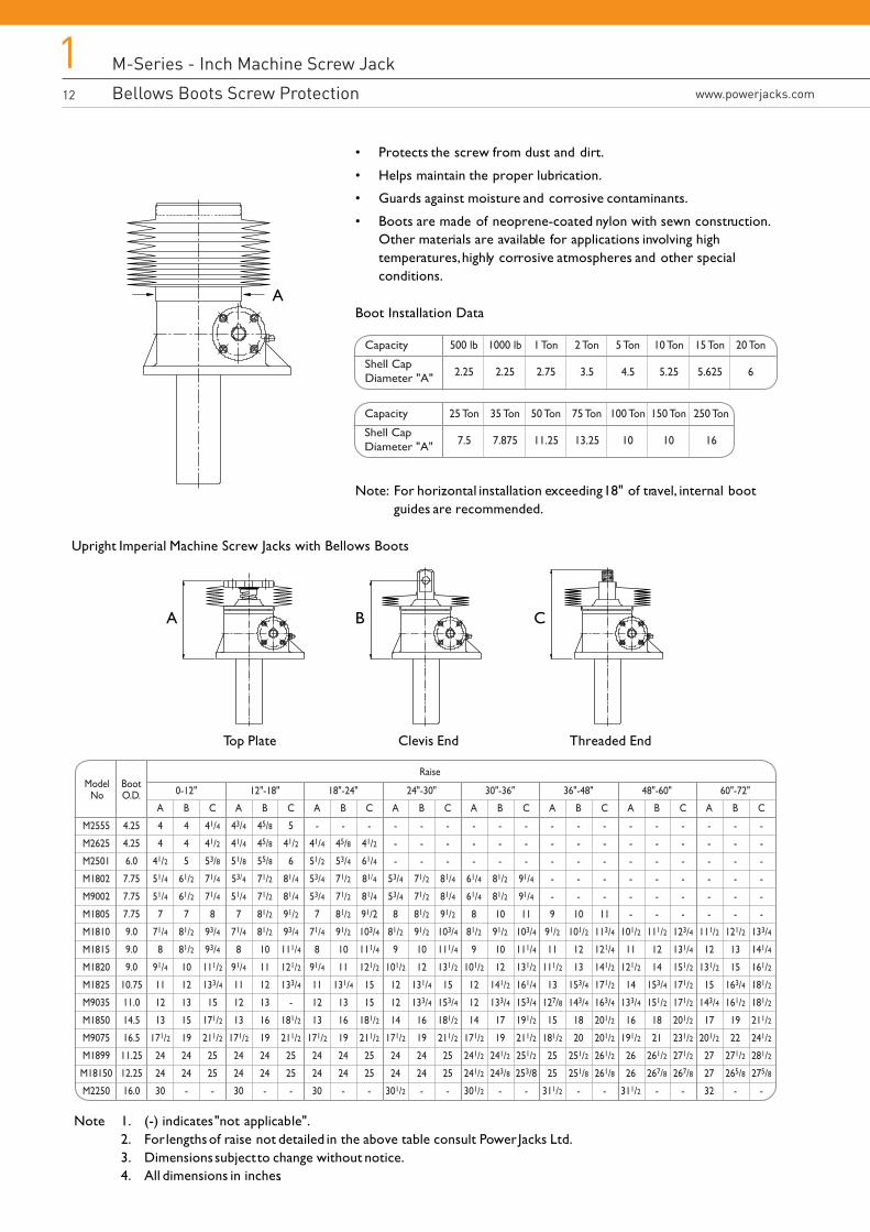
• Protects the screw from dust and dirt.
• Helps maintain the proper lubrication.
• Guards against moisture and corrosive contaminants.
• Boots are made of neoprene-coated nylon with sewn construction.Other materials are available for applications involving hightemperatures, highly corrosive atmospheres and other specialconditions.
Boot Installation Data
Note: For horizontal installation exceeding 18" of travel, internal bootguides are recommended.
Upright Imperial Machine Screw Jacks with Bellows Boots
ModelNo
M2555
M2625
M2501
M1802
M9002
M1805
M1810
M1815
M1820
M1825
M9035
M1850
M9075
M1899
M18150
M2250
4.25
4.25
6.0
7.75
7.75
7.75
9.0
9.0
9.0
10.75
11.0
14.5
16.5
11.25
12.25
16.0
A
4
4
41/2
51/4
51/4
7
71/4
8
91/4
11
12
13
171/2
24
24
30
B
4
4
5
61/2
61/2
7
81/2
81/2
10
12
13
15
19
24
24
-
0-12" 12"-18" 18"-24" 24"-30"
Raise
30"-36" 36"-48" 48"-60" 60"-72"
C
41/4
41/2
53/8
71/4
71/4
8
93/4
93/4
111/2
133/4
15
171/2
211/2
25
25
-
A
43/4
41/4
51/8
53/4
51/4
7
71/4
8
91/4
11
12
13
171/2
24
24
30
B
45/8
45/8
55/8
71/2
71/2
81/2
81/2
10
11
12
13
16
19
24
24
-
C
5
41/2
6
81/4
81/4
91/2
93/4
111/4
121/2
133/4
-
181/2
211/2
25
25
-
A
-
41/4
51/2
53/4
53/4
7
71/4
8
91/4
11
12
13
171/2
24
24
30
B
-
45/8
53/4
71/2
71/2
81/2
91/2
10
11
131/4
13
16
19
24
24
-
C
-
41/2
61/4
81/4
81/4
91/2
103/4
111/4
121/2
15
15
181/2
211/2
25
25
-
A
-
-
-
53/4
53/4
8
81/2
9
101/2
12
12
14
171/2
24
24
301/2
B
-
-
-
71/2
71/2
81/2
91/2
10
12
131/4
133/4
16
19
24
24
-
C
-
-
-
81/4
81/4
91/2
103/4
111/4
131/2
15
153/4
181/2
211/2
25
25
-
A
-
-
-
61/4
61/4
8
81/2
9
101/2
12
12
14
171/2
241/2
241/2
301/2
B
-
-
-
81/2
81/2
10
91/2
10
12
141/2
133/4
17
19
241/2
243/8
-
C
-
-
-
91/4
91/4
11
103/4
111/4
131/2
161/4
153/4
191/2
211/2
251/2
253/8
-
A
-
-
-
-
-
9
91/2
11
111/2
13
127/8
15
181/2
25
25
311/2
B
-
-
-
-
-
10
101/2
12
13
153/4
143/4
18
20
251/2
251/8
-
C
-
-
-
-
-
11
113/4
121/4
141/2
171/2
163/4
201/2
201/2
261/2
261/8
-
A
-
-
-
-
-
-
101/2
11
121/2
14
133/4
16
191/2
26
26
311/2
B
-
-
-
-
-
-
111/2
12
14
153/4
151/2
18
21
261/2
267/8
-
C
-
-
-
-
-
-
123/4
131/4
151/2
171/2
171/2
201/2
231/2
271/2
267/8
-
A
-
-
-
-
-
-
111/2
12
131/2
15
143/4
17
201/2
27
27
32
B
-
-
-
-
-
-
121/2
13
15
163/4
161/2
19
22
271/2
265/8
-
C
-
-
-
-
-
-
133/4
141/4
161/2
181/2
181/2
211/2
241/2
281/2
275/8
-
BootO.D.
Capacity
Shell CapDiameter "A"
25 Ton
7.5
35 Ton
7.875
50 Ton
11.25
75 Ton
13.25
100 Ton
10
150 Ton
10
250 Ton
16
Capacity
Shell CapDiameter "A"
500 lb
2.25
1000 lb
2.25
1 Ton
2.75
2 Ton
3.5
5 Ton
4.5
10 Ton
5.25
15 Ton
5.625
20 Ton
6
Note 1. (-) indicates "not applicable".2. For lengths of raise not detailed in the above table consult Power Jacks Ltd.3. Dimensions subject to change without notice.4. All dimensions in inches.
A
A B C
Top Plate Clevis End Threaded End
M-Series - Inch Machine Screw Jack
Bellows Boots Screw Protection
M-Series - Inch Machine Screw Jack
Bellows Boot Screw Protectionwww.powerjacks.com
113
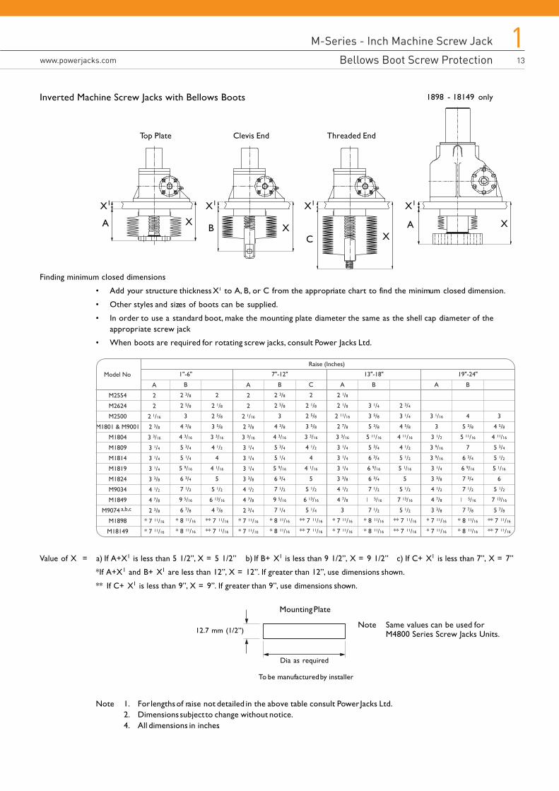
Inverted Machine Screw Jacks with Bellows Boots
Finding minimum closed dimensions
• Add your structure thickness X1 to A, B, or C from the appropriate chart to find the minimum closed dimension.
• Other styles and sizes of boots can be supplied.
• In order to use a standard boot, make the mounting plate diameter the same as the shell cap diameter of theappropriate screw jack
• When boots are required for rotating screw jacks, consult Power Jacks Ltd.
Raise (Inches)
Model No
M2554
M2624
M2500
M1801 & M9001
M1804
M1809
M1814
M1819
M1824
M9034
M1849
M9074 a,b,c
M1898
M18149
A
2
2
2 1/16
2 3/8
3 3/16
3 1/4
3 1/4
3 1/4
3 3/8
4 1/2
4 7/8
2 3/8
* 7 11/16
* 7 11/16
B
2 3/8
2 5/8
3
4 3/8
4 3/16
5 3/4
5 1/4
5 9/16
6 3/4
7 1/2
9 5/16
6 7/8
* 8 11/16
* 8 11/16
2
2 1/8
2 5/8
3 5/8
3 3/16
4 1/2
4
4 1/16
5
5 1/2
6 13/16
4 7/8
** 7 11/16
** 7 11/16
A
2
2
2 1/16
2 3/8
3 3/16
3 1/4
3 1/4
3 1/4
3 3/8
4 1/2
4 7/8
2 3/4
* 7 11/16
* 7 11/16
A
2 1/8
2 1/8
2 11/16
2 7/8
3 3/16
3 1/4
3 1/4
3 1/4
3 3/8
4 1/2
4 7/8
3
* 7 11/16
* 7 11/16
A
3 1/16
3
3 1/2
3 9/16
3 9/16
3 1/4
3 3/8
4 1/2
4 7/8
3 3/8
* 7 11/16
* 7 11/16
B
4
5 3/8
5 11/16
7
6 3/4
6 9/16
7 3/4
7 1/25/16
7 7/8
* 8 11/16
* 8 11/16
3
4 5/8
4 11/16
5 3/4
5 1/2
5 1/16
6
5 1/2
7 13/16
5 7/8
** 7 11/16
** 7 11/16
B
2 3/8
2 5/8
3
4 3/8
4 3/16
5 3/4
5 1/4
5 9/16
6 3/4
7 1/2
9 5/16
7 1/4
* 8 11/16
* 8 11/16
B
3 1/4
3 5/8
5 3/8
5 11/16
5 3/4
6 3/4
6 9/16
6 3/4
7 1/25/16
7 1/2
* 8 11/16
* 8 11/16
2 3/4
3 1/4
4 5/8
4 11/16
4 1/2
5 1/2
5 1/16
5
5 1/2
7 13/16
5 1/2
** 7 11/16
** 7 11/16
C
2
2 1/8
2 5/8
3 5/8
3 3/16
4 1/2
4
4 1/16
5
5 1/2
6 13/16
5 1/4
** 7 11/16
** 7 11/16
1"-6" 7"-12" 13"-18" 19"-24"
Top Plate Clevis End Threaded End
1898 - 18149 only
A
X1
B
X1
C
X1
A
X1
XX
XX
Value of X = a) If A+X1 is less than 5 1/2”, X = 5 1/2” b) If B+ X1 is less than 9 1/2”, X = 9 1/2” c) If C+ X1 is less than 7”, X = 7”
*If A+X1 and B+ X1 are less than 12”, X = 12”. If greater than 12”, use dimensions shown.
** If C+ X1 is less than 9”, X = 9”. If greater than 9”, use dimensions shown.
Dia as required
Mounting Plate
12.7 mm (1/2”)
To be manufactured by installer
Note Same values can be used forM4800 Series Screw Jacks Units.
Note 1. For lengths of raise not detailed in the above table consult Power Jacks Ltd.2. Dimensions subject to change without notice.4. All dimensions in inches.
M-Series - Inch Machine Screw Jack
Worm Flange Bolt Dimensions14
1www.powerjacks.com
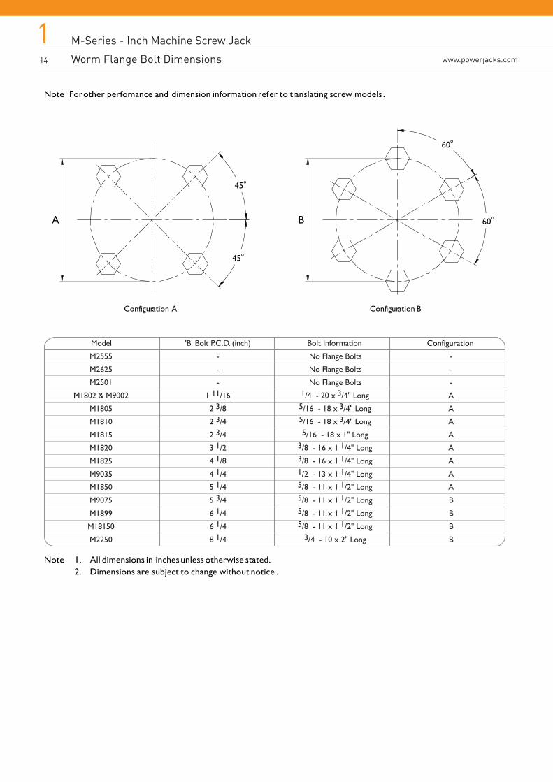
Note For other performance and dimension information refer to translating screw models .
A
45o
45o
B 60o
60o
Model
M2555
M2625
M2501
M1802 & M9002
M1805
M1810
M1815
M1820
M1825
M9035
M1850
M9075
M1899
M18150
M2250
'B' Bolt P.C.D. (inch)
-
-
-
1 11/16
2 3/8
2 3/4
2 3/4
3 1/2
4 1/8
4 1/4
5 1/4
5 3/4
6 1/4
6 1/4
8 1/4
Bolt Information
No Flange Bolts
No Flange Bolts
No Flange Bolts1/4 - 20 x 3/4" Long5/16 - 18 x 3/4" Long5/16 - 18 x 3/4" Long5/16 - 18 x 1" Long
3/8 - 16 x 1 1/4" Long3/8 - 16 x 1 1/4" Long1/2 - 13 x 1 1/4" Long5/8 - 11 x 1 1/2" Long5/8 - 11 x 1 1/2" Long5/8 - 11 x 1 1/2" Long5/8 - 11 x 1 1/2" Long
3/4 - 10 x 2" Long
-
-
-
A
A
A
A
A
A
A
A
B
B
B
B
Conf
Configuration
iguration A Configuration B
Note 1. All dimensions in inches unless otherwise stated.2. Dimensions are subject to change without notice .
M-Series - Inch Machine Screw Jack
Worm Flange Bolt Dimensions
M-Series - Inch Machine Screw Jack
Motor Adapters for Inch Screw Jackswww.powerjacks.com
115
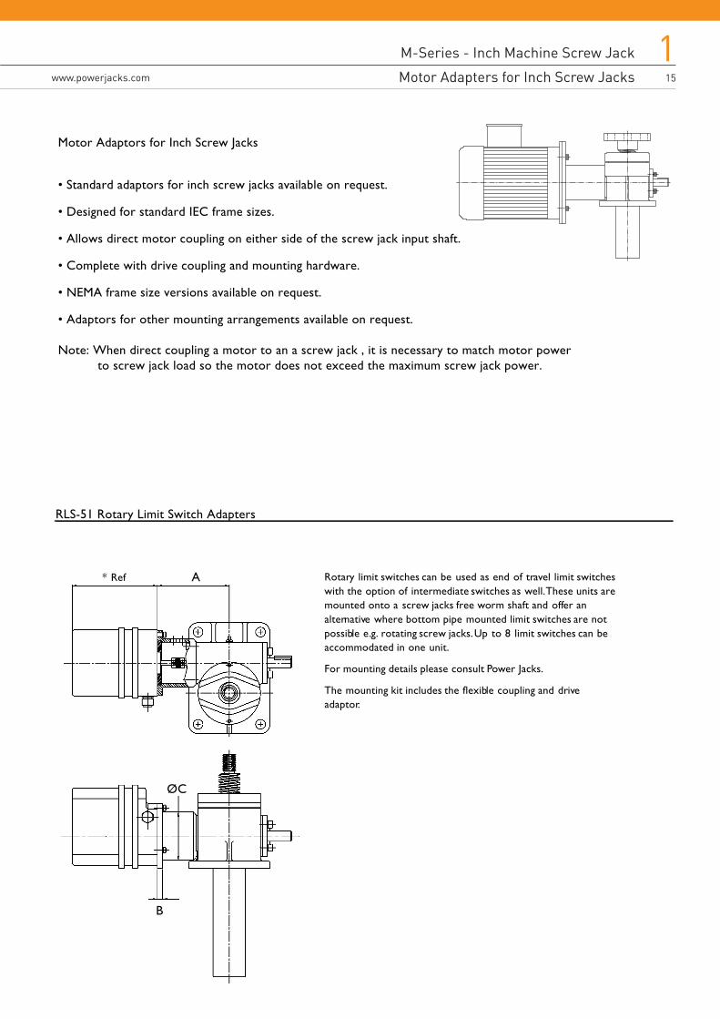
Rotary limit switches can be used as end of travel limit switcheswith the option of intermediate switches as well. These units aremounted onto a screw jacks free worm shaft and offer analternative where bottom pipe mounted limit switches are notpossible e.g. rotating screw jacks. Up to 8 limit switches can beaccommodated in one unit.
For mounting details please consult Power Jacks.
The mounting kit includes the flexible coupling and driveadaptor.
A* Ref
ØC
B
RLS-51 Rotary Limit Switch Adapters
Motor Adaptors for Inch Screw Jacks
• Standard adaptors for inch screw jacks available on request.
• Designed for standard IEC frame sizes.
• Allows direct motor coupling on either side of the screw jack input shaft.
• Complete with drive coupling and mounting hardware.
• NEMA frame size versions available on request.
• Adaptors for other mounting arrangements available on request.
Note: When direct coupling a motor to an a screw jack , it is necessary to match motor power to screw jack load so the motor does not exceed the maximum screw jack power.
M-Series - Inch Machine Screw Jack
SKA Rotary Limit Switch Adaptors16
1www.powerjacks.com
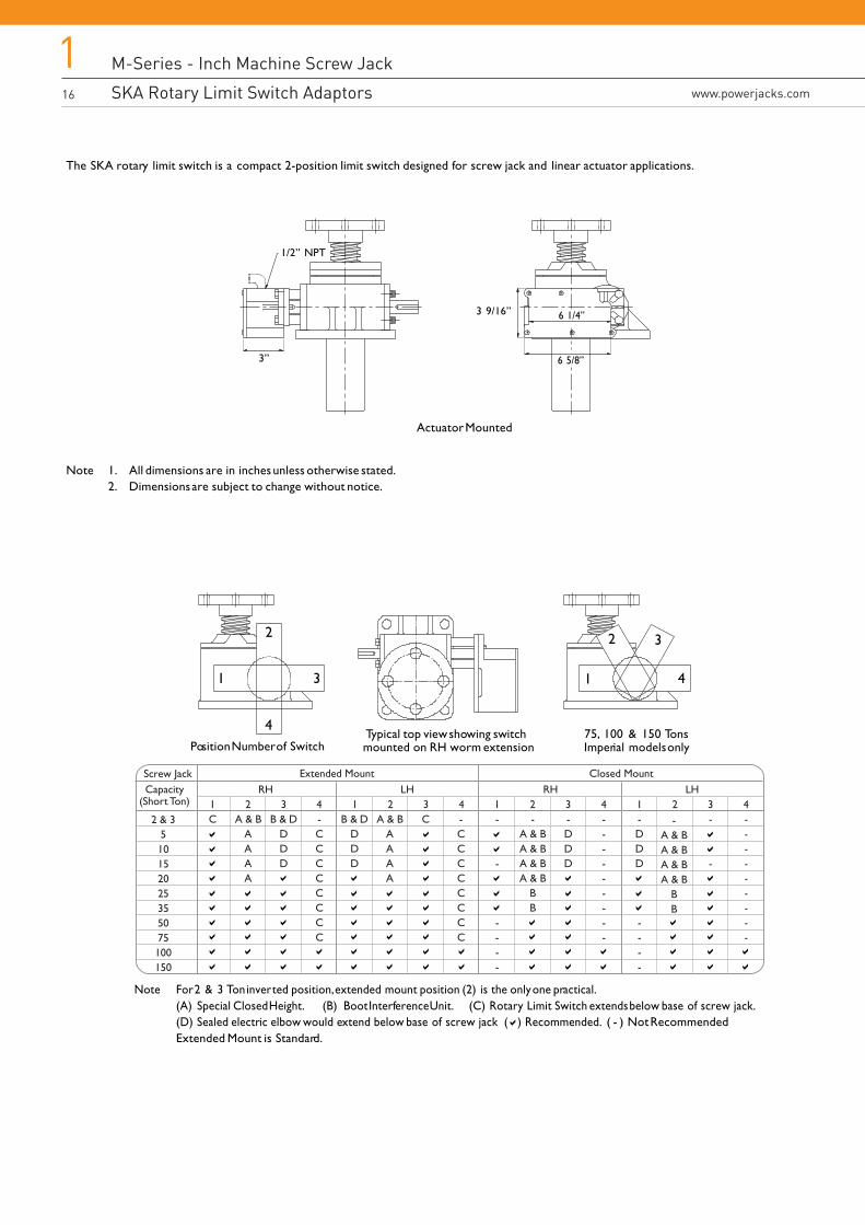
Typical top view showing switchmounted on RH worm extensionPosition Number of Switch
75, 100 & 150 TonsImperial models only
2
1 3
4
2
1
3
4
Capacity(Short Ton)
Screw Jack
2 & 3510152025355075100150
1C
2A & B
AAAA
3RH LH RH
Extended Mount Closed MountLH
B & DDDD
4-CCCCCCCC
-CCCCCCCC
1 2 3 4 1-
-
----
2-
A & BA & BA & BA & B
BB
3-DDD
4---------
1-DDD
----
2-
A & BA & BA & BA & B
BB
3-
-
4---------
CB & DDDD
A & BAAAA
Note For 2 & 3 Ton inverted position, extended mount position (2) is the only one practical.(A) Special Closed Height. (B) Boot Interference Unit. (C) Rotary Limit Switch extends below base of screw jack.(D) Sealed electric elbow would extend below base of screw jack ( ) Recommended. ( - ) Not RecommendedExtended Mount is Standard.
The SKA rotary limit switch is a compact 2-position limit switch designed for screw jack and linear actuator applications.
Note 1. All dimensions are in inches unless otherwise stated.2. Dimensions are subject to change without notice.
3”
1/2” NPT
3 9/16”
6 5/8”
6 1/4”
Actuator Mounted
M-Series - Inch Machine Screw Jack
SKA Rotary Limit Switch Adaptors
M-Series - Inch Machine Screw Jack
Mounting and Adjustment for SKA Rotary Limit Switcheswww.powerjacks.com
117
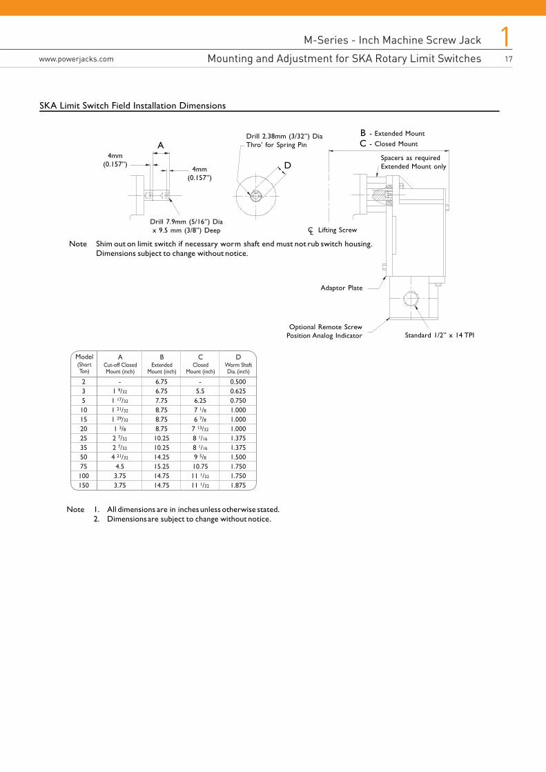
CClosed
Mount (inch)
-5.56.257 1/86 7/8
7 13/32
8 1/16
8 1/16
9 5/810.7511 1/32
11 1/32
BExtended
Mount (inch)
6.756.757.758.758.758.7510.2510.2514.2515.2514.7514.75
ACut-off ClosedMount (inch)
-1 9/32
1 17/32
1 21/32
1 29/32
1 3/82 7/32
2 7/32
4 21/32
4.53.753.75
Model(ShortTon)
23510152025355075100150
DWorm ShaftDia. (inch)
0.5000.6250.7501.0001.0001.0001.3751.3751.5001.7501.7501.875
A4mm
(0.157”)4mm
(0.157”)
Drill 7.9mm (5/16”) Diax 9.5 mm (3/8”) Deep
D
Drill 2.38mm (3/32”) DiaThro’ for Spring Pin
BC
- Extended Mount- Closed Mount
Spacers as requiredExtended Mount only
Adaptor Plate
Optional Remote ScrewPosition Analog Indicator Standard 1/2” x 14 TPI
Note Shim out on limit switch if necessary worm shaft end must not rub switch housing. Dimensions subject to change without notice.
Note 1. All dimensions are in inches unless otherwise stated.2. Dimensions are subject to change without notice.
SKA Limit Switch Field Installation Dimensions
C Lifting ScrewL
M-Series - Stainless Steel Screw Jack
Inch / Imperial Stainless Steel Machine Screw Jacks18
2www.powerjacks.com18 www.powerjacks.com
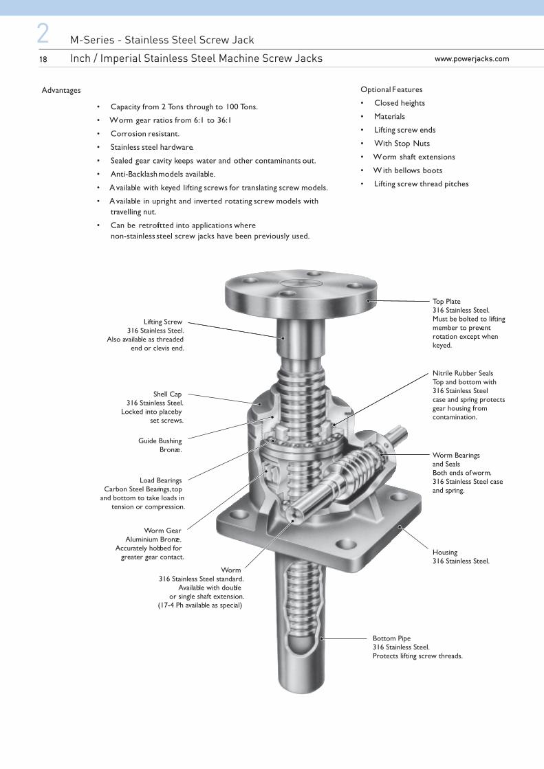
Lifting Screw316 Stainless Steel.
Also available as threadedend or clevis end.
Shell Cap316 Stainless Steel.
Locked into place byset screws.
Load BearingsCarbon Steel Bearings, top
and bottom to take loads intension or compression.
Worm GearAluminium Bronze.
Accurately hobbed forgreater gear contact.
Worm316 Stainless Steel standard.
Available with doubleor single shaft extension.
(17-4 Ph available as special)
Worm Bearingsand SealsBoth ends of worm.316 Stainless Steel caseand spring.
Bottom Pipe316 Stainless Steel.Protects lifting screw threads.
Housing316 Stainless Steel.
Guide BushingBronze.
Nitrile Rubber SealsTop and bottom with316 Stainless Steelcase and spring protectsgear housing fromcontamination.
Top Plate316 Stainless Steel.Must be bolted to liftingmember to preventrotation except whenkeyed.
Advantages
• Capacity from 2 Tons through to 100 Tons.
• Worm gear ratios from 6:1 to 36:1
• Corrosion resistant.
• Stainless steel hardware.
• Sealed gear cavity keeps water and other contaminants out.
• Anti-Backlash models available.
• Available with keyed lifting screws for translating screw models.
• Available in upright and inverted rotating screw models withtravelling nut.
• Can be retrofitted into applications where non-stainless steel screw jacks have been previously used.
Optional Features
• Closed heights
• Materials
• Lifting screw ends
• With Stop Nuts
• Worm shaft extensions
• W ith bellows boots
• Lifting screw thread pitches
M-Series - Stainless Steel Screw Jack
Inch / Imperial Stainless Steel Machine Screw Jacks
M-Series - Stainless Steel Screw Jack
Performance of Standard Inch Stainless Steel Screw Jackswww.powerjacks.com
219www.powerjacks.com 19
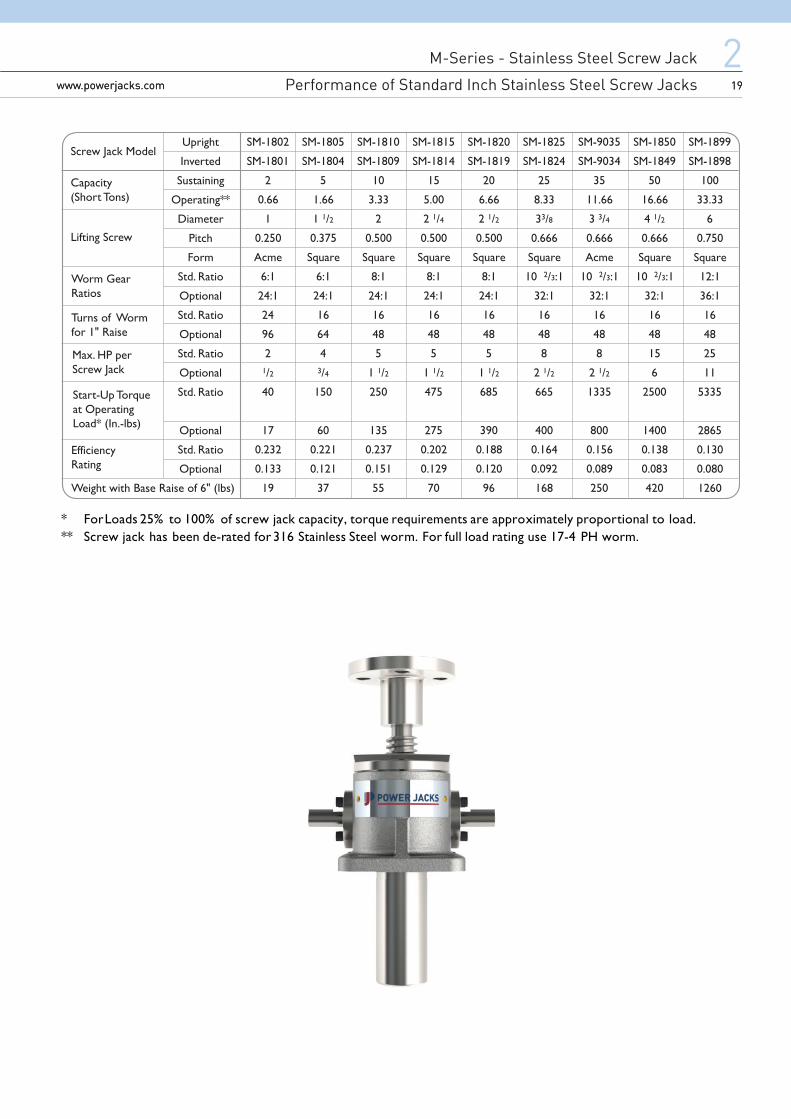
SM-1802
SM-1801
2
0.66
1
0.250
Acme
6:1
24:1
24
96
21/2
40
17
0.232
0.133
19
SM-1805
SM-1804
5
1.66
1 1/2
0.375
Square
6:1
24:1
16
64
43/4
150
60
0.221
0.121
37
SM-1810
SM-1809
10
3.33
2
0.500
Square
8:1
24:1
16
48
5
1 1/2
250
135
0.237
0.151
55
SM-1815
SM-1814
15
5.00
2 1/4
0.500
Square
8:1
24:1
16
48
5
1 1/2
475
275
0.202
0.129
70
SM-1820
SM-1819
20
6.66
2 1/2
0.500
Square
8:1
24:1
16
48
5
1 1/2
685
390
0.188
0.120
96
SM-1825
SM-1824
25
8.33
33/8
0.666
Square
10 2/3:1
32:1
16
48
8
2 1/2
665
400
0.164
0.092
168
SM-9035
SM-9034
35
11.66
3 3/4
0.666
Acme
10 2/3:1
32:1
16
48
8
2 1/2
1335
800
0.156
0.089
250
SM-1850
SM-1849
50
16.66
4 1/2
0.666
Square
10 2/3:1
32:1
16
48
15
6
2500
1400
0.138
0.083
420
SM-1899
SM-1898
100
33.33
6
0.750
Square
12:1
36:1
16
48
25
11
5335
2865
0.130
0.080
1260
Upright
Inverted
Sustaining
Operating**
Diameter
Pitch
Form
Std. Ratio
Optional
Std. Ratio
Optional
Std. Ratio
Optional
Std. Ratio
Optional
Std. Ratio
Optional
Screw Jack Model
Capacity(Short Tons)
Start-Up Torqueat OperatingLoad* (In.-lbs)
EfficiencyRating
Lifting Screw
Worm GearRatios
Turns of Wormfor 1" Raise
Max. HP perScrew Jack
Weight with Base Raise of 6" (lbs)
* For Loads 25% to 100% of screw jack capacity, torque requirements are approximately proportional to load.** Screw jack has been de-rated for 316 Stainless Steel worm. For full load rating use 17-4 PH worm.
M-Series - Stainless Steel Screw Jack
Inch Stainless Steel Screw Jack Dimensions20
2www.powerjacks.com20 www.powerjacks.com
Mod
elN
o
SM-1
802
SM-1
805
SM-1
810
SM-1
815
SM-1
820
SM-1
825
SM-9
035
SM-1
850
SM-1
899
Sust
aini
ng
2 5 10 15 20 25 35 50 100
Ope
ratin
g
0.66
1.66
3.33
5.00
6.66
8.33
11.6
6
16.6
6
33.3
3
Cap
acity
(Sho
r t To
ns)
S 3.5
8.00
8.75
9.25
11.0
0
13.7
5
15.5
0
9.75
20.7
5
R 1.75
3.00
2.88
3.38
4.13
5.13
6.00
4.88
8.00
T 3.5
4.50
5.50
5.50
5.50
7.00
7.00
11.0
0
11.5
0
V 1.12
1.50
1.80
1.80
1.50
2.30
2.10
4.40
3.40
X .41
.69
.81
.81
.81
1.06
1.62
1.38 *
Y 3.00
3.00
4.13
4.13
4.13
6.00
7.75
8.75 *
Z .41
.69
.81
.81
1.12
1.38
1.62
1.88 •
a .75
1.19
1.31
1.38
1.75
2.13
2.63
3.25 *
b 1.5
.75
.88
.88
1.13
1.38
1.38
1.88 *
Keys
eat
(b x
h x
L)
.125
x 0
.060
x 1
.00
LG
.188
x .0
94 x
1.2
5 LG
.250
x .1
25 x
1.5
0 LG
.250
x .1
25 x
1.5
0 LG
.250
x .1
25 x
1.5
0 LG
.313
x .1
56 x
2.0
0 LG
.313
x .1
56 x
2.0
0 LG
.375
x .1
88 x
2.2
5 LG
.500
x .2
50 x
3.0
0 LG
U 7.00
9.00
11.0
0
11.0
0
11.0
0
14.0
0
14.0
0
22.0
0
23.0
0
Q 7.00
6.00
7.50
7.75
8.25
10.2
5
10.2
5
19.7
5
24.5
0
P 3.5
3.00
3.75
3.88
4.13
5.13
5.13
9.88
12.2
5
N 2.00
6.50
7.00
7.50
8.75
11.0
0
12.5
0
6.00 *
M 1.00
2.25
2.00
2.50
3.00
3.75
4.50
3.00 *
H .50
.60
.94
.94
.94
.94
1.31
1.25
2.94
.500
.749
1.00
0
1.00
0
1.00
0
1.37
5
1.37
5
1.50
0
1.75
0
+.00
0-.0
02
+.00
0-.0
02
+.00
0-.0
02
+.00
0-.0
02
+.00
0-.0
02
+.00
0-.0
02
+.00
0-.0
02
+.00
0-.0
02
+.00
0-.0
02
D .50
.50
.50
.63
.75
1.00
1.25
1.25
1.50
G 4.25
4.50
5.75
5.75
5.75
8.50
10.5
0
11.2
5
14.0
0
F 1.66
2.38
2.88
2.88
3.50
4.50
4.50
5.63
7.00
L 6.00
4.50
5.75
6.00
6.00
7.50
7.50
16.0
0
*
K 3.00
2.25
2.88
3.00
3.00
3.75
3.75
8.00 *
J
1.70
2
2.18
8
2.59
8
2.59
8
2.59
8
3.75
0
3.75
0
5.31
3
7.50
0
+.00
3-.0
00
+.00
3-.0
00
+.00
3-.0
00
+.00
3-.0
00
+.00
3-.0
00
+.00
3-.0
00
+.00
3-.0
00
+.00
3-.0
00
+.00
3-.0
00
WE
1.75
0
±.00
5
2.25
0
±.00
5
2.25
0
±.00
5
2.75
0
±.00
5
3.25
0
±.00
5
4.00
0
±.00
5
4.00
0
±.00
5
4.75
0
±.00
5
6.00
0
±.00
5
B 4.56
5.88
6.00
6.31
8.00
9.75
9.56
11.3
8
18.5
0
A 5.50
7.50
7.75
8.00
10.2
5
11.7
5
12.5
0
13.5
0
24.0
0
C
Trav
el
Trav
el
+3 /
8
Trav
el
+1 /
4
Trav
el
+1 /
2
Trav
el- 1
/ 4
Trav
el
+1 /
4
Trav
el
+1 /
4
Trav
el
Trav
el
+1 /
2
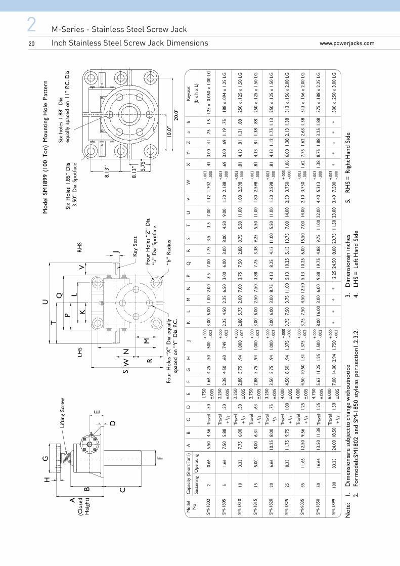
Mod
el S
M18
99 (
100
Ton)
Mou
ntin
g H
ole
Pat
tern
Not
e:1.
Dim
ensi
ons a
re s
ubje
ct to
cha
nge
with
out n
otic
e .3.
Dim
ensi
ons in
inch
es.
5.R
HS
= R
ight
Han
d Si
de2.
For m
odel
s SM
1802
and
SM
-185
0 st
yle
as p
er s
ectio
n 1.2
.3.2
.4.
LHS
= Le
ft H
and
Side
D
E
GH
B
A(C
lose
dH
eigh
t)
C
F
Lift
ing
Scre
wT
QP
LK
V
SW
U
Key
Sea
t
JN
RM
Four
Hol
es “
Z”
Dia
“a”
Dia
Spo
tfac
e
“b”
Rad
ius
Four
Hol
es “
X”
Dia
equ
all y
spac
ed o
n “Y
” D
ia P
.C.
RH
SLH
S
Six
hole
s 1.
88”
Dia
equa
lly s
pace
d on
11”
P.C
. Dia
8.13
”
8.13
” 5.75
”
10.0
”20
.0”
Six
Hol
es 1
.85 ”
Dia
3.50
” D
ia S
potf
ace
M-Series - Stainless Steel Screw Jack
Inch Stainless Steel Screw Jack Dimensions
M-Series - Stainless Steel Screw Jack
Inch Stainless Steel Screw Jack Dimensionswww.powerjacks.com
221www.powerjacks.com 21
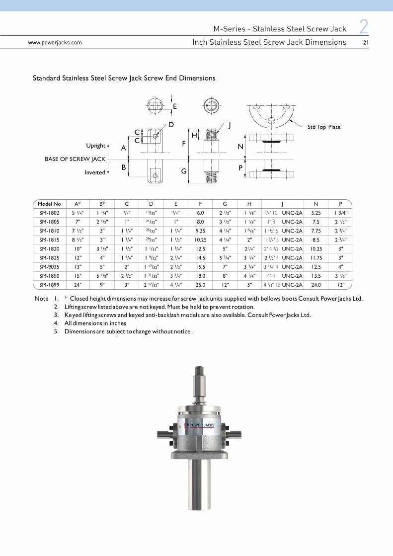
Model No
SM-1802
SM-1805
SM-1810
SM-1815
SM-1820
SM-1825
SM-9035
SM-1850
SM-1899
A*
5 1/4"
7"
7 1/2"
8 1/2"
10"
12"
13"
15"
24"
B*
1 3/4"
2 1/2"
3"
3"
3 1/2"
4"
5"
5 1/2"
9"
C3/4"
1"
1 1/4"
1 1/4"
1 1/2"
1 3/4"
2"
2 1/2"
3"
E3/4"
1"
1 1/4"
1 1/2"
1 3/4"
2 1/4"
2 1/2"
3 1/4"
4 1/4"
D13/32"21/32"25/32"29/32"
1 1/32"
1 9/32"
1 17/32"
1 21/32"
2 17/32"
F
6.0
8.0
9.25
10.25
12.5
14.5
15.5
18.0
25.0
G
2 1/2"
3 1/2"
4 1/4"
4 1/4"
5"
5 3/4"
7"
8"
12"
H J
1 1/8"
1 1/8"
1 5/8"
2"
21/4"
3 1/4"
3 3/4"
4 1/4"
5"
N
5.25
7.5
7.75
8.5
10.25
11.75
12.5
13.5
24.0
UNC-2A
UNC-2A
UNC-2A
UNC-2A
UNC-2A
UNC-2A
UNC-2A
UNC-2A
UNC-2A
P
1 3/4"
2 1/2"
2 3/4"
2 3/4"
3"
3"
4"
3 1/2"
12"
3/4
1 1/2
1 3/41/2
2 1/2
3 1/4
4 1/2
Standard Stainless Steel Screw Jack Screw End Dimensions
Note 1. * Closed height dimensions may increase for screw jack units supplied with bellows boots. Consult Power Jacks Ltd.2. Lifting screw listed above are not keyed. Must be held to prevent rotation.3. Keyed lifting screws and keyed anti-backlash models are also available. Consult Power Jacks Ltd.4. All dimensions in inches.5. Dimensions are subject to change without notice .
E
D JCC
A
B
F
G
H
P
NUpright
Std Top Plate
Inverted
BASE OF SCREW JACK
M-Series - Inch Ball Screw Jack
Inch / Imperial Ball Screw Jacks22
3www.powerjacks.com22 www.powerjacks.com22 www.powerjacks.com
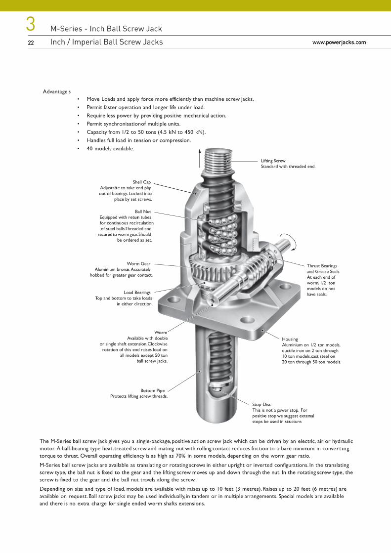
Shell CapAdjustable to take end playout of bearings. Locked into
place by set screws.
Ball NutEquipped with return tubesfor continuous recirculationof steel balls. Threaded and
secured to worm gear. Shouldbe ordered as set.
Worm GearAluminium bronze. Accurately
hobbed for greater gear contact.
WormAvailable with double
or single shaft extension. Clockwiserotation of this end raises load on
all models except 50 tonball screw jacks.
Load BearingsTop and bottom to take loads
in either direction.
Bottom PipeProtects lifting screw threads.
Lifting ScrewStandard with threaded end.
Thrust Bearingsand Grease SealsAt each end ofworm. 1/2 tonmodels do nothave seals.
Stop-DiscThis is not a power stop. Forpositive stop we suggest externalstops be used in structure.
HousingAluminium on 1/2 ton models,ductile iron on 2 ton through10 ton models, cast steel on20 ton through 50 ton models.
Advantage s• Move Loads and apply force more efficiently than machine screw jacks.• Permit faster operation and longer life under load.• Require less power by providing positive mechanical action.• Permit synchronisation of multiple units.• Capacity from 1/2 to 50 tons (4.5 kN to 450 kN).• Handles full load in tension or compression.• 40 models available.
The M-Series ball screw jack gives you a single-package, positive action screw jack which can be driven by an electric, air or hydraulicmotor. A ball-bearing type heat-treated screw and mating nut with rolling contact reduces friction to a bare minimum in convert ingtorque to thrust. Overall operating efficiency is as high as 70% in some models, depending on the worm gear ratio.
M-Series ball screw jacks are available as translating or rotating screws in either upright or inverted configurations. In the translatingscrew type, the ball nut is fixed to the gear and the lifting screw moves up and down through the nut. In the rotating screw type, thescrew is fixed to the gear and the ball nut travels along the screw.
Depending on size and type of load, models are available with raises up to 10 feet (3 metres). Raises up to 20 feet (6 metres) areavailable on request. Ball screw jacks may be used individually, in tandem or in multiple arrangements. Special models are availableand there is no extra charge for single ended worm shafts extensions.
M-Series - Inch Ball Screw Jack
Inch / Imperial Ball Screw Jacks
M-Series - Inch Ball Screw Jack
Inch Ball Screw Jack Modelswww.powerjacks.com
323www.powerjacks.com 23www.powerjacks.com 23
Features
• High Speed - Low friction permits linear motion in some models up to 300 inches/min (7.62 m/min) at 1800 rpm wormshaft speeds, providing maximum horsepower ratings are not exceeded.
• Precise Positioning - Can be controlled accurately for positioning within thousandths of an inch.
• Positive Action - Operates with a high degree of reliability, without the need for costly pumps, hoses or valves
• Long-Life - Low friction means longer operating life.
• Low Power Usage - Highly efficient design means less power is needed to achieve a given thrust; power needs aremuch as two-thirds that of machine screw jacks.
Options
• 3 Standard Gear Ratios - Wide selection of gear ratios, increases the amount of raise rates available.
• 2 Ball Screw Lead Options - On the 2, 5 and 10 ton models there is the option of either the standard or a 1“(25.4 mm) lead for rapid raise rates.
• Screw on Ends - The standard screw jack has a threaded end to which clevis or top plates can be screwed. Note: these items are shipped loose and must be spot drilled before seating set screws in field installations.
• Bellows Boot Option - Protects the screw from dust, dirt, moisture and corrosive contaminants.
• Double Clevis End Option - Incorporates a special clevis end bottompipe and standard clevis end on the liftingscrew.
Note:
Attachments
IEC and Nema C-Face flanges, motors, gear boxes, reducers and couplings available for single screw jack drive or multiple screw jackarrangements
Motion control components include motor drives, Motion Controllers with operator interfaces, encoders, limit switches, potentiometersand meters with LCD display
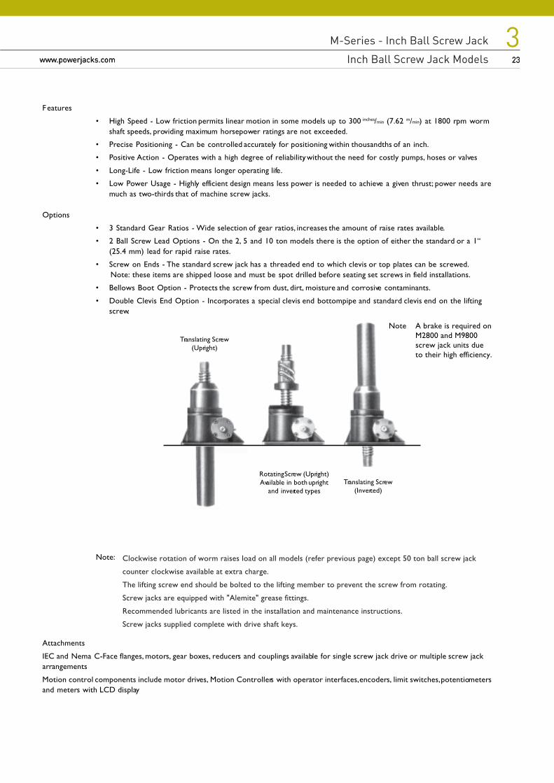
Translating Screw(Upright)
Rotating Screw (Upright)Available in both upright
and inverted typesTranslating Screw
(Inverted)
Note A brake is required onM2800 and M9800screw jack units dueto their high efficiency.
Clockwise rotation of worm raises load on all models (refer previous page) except 50 ton ball screw jack
counter clockwise available at extra charge.
The lifting screw end should be bolted to the lifting member to prevent the screw from rotating.
Screw jacks are equipped with "Alemite" grease fittings.
Recommended lubricants are listed in the installation and maintenance instructions.
Screw jacks supplied complete with drive shaft keys.
M-Series - Inch Ball Screw Jack
Performance of Standard M-Series - Inch Ball Screw Jacks24
3www.powerjacks.com24 www.powerjacks.com
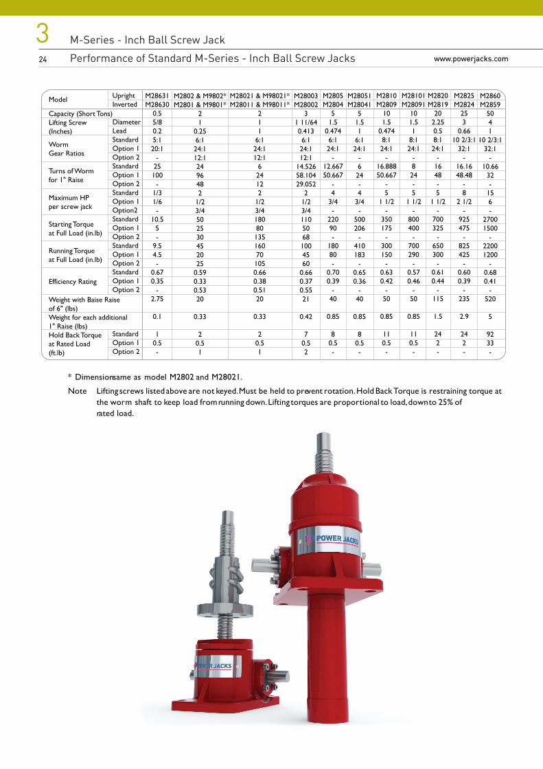
M2860M2859
5041
10 2/3:132:1
-10.66
32-
156-
27001500
-22001200
-0.680.41
-520
5
9233-
Model
Capacity (Short Tons)Lifting Screw(Inches)
WormGear Ratios
Turns of Wormfor 1" Raise
Maximum HPper screw jack
Starting Torqueat Full Load (in.lb)
Running Torqueat Full Load (in.lb)
Efficiency Rating
Weight with Baise Raiseof 6" (lbs)Weight for each additional1" Raise (lbs)Hold Back Torqueat Rated Load(ft.lb)
M2825M2824
253
0.6610 2/3:1
32:1-
16.1648.48
-8
2 1/2-
925475
-825425
-0.600.39
-235
2.9
242-
M2820M2819
202.250.58:124:1
-1648-5
1 1/2-
700325
-650300
-0.610.44
-115
1.5
242-
M28003M28002
31 11/640.4136:124:112:1
14.52658.10429.052
21/23/411050681004560
0.660.370.5521
0.42
70.52
M28631M28630
0.55/80.25:120:1
-25100
-1/31/6-
10.55-
9.54.5-
0.670.35
-2.75
0.1
10.5-
M2805M2804
51.5
0.4746:124:1
-12.66750.667
-4
3/4-
22090-
18080-
0.700.39
-40
0.85
80.5-
UprightInverted
DiameterLeadStandardOption 1Option 2StandardOption 1Option 2StandardOption 1Option2StandardOption 1Option 2StandardOption 1Option 2StandardOption 1Option 2
StandardOption 1Option 2
M2810M2809
101.5
0.4748:124:1
-16.88850.667
-5
1 1/2-
350175
-300150
-0.630.42
-50
0.85
110.5-
M2802 & M9802*M2801 & M9801*
21
0.256:124:112:12496482
1/23/4502530452025
0.590.330.5320
0.33
20.51
M28021 & M98021*M28011 & M98011*
211
6:124:112:1
624122
1/23/418080135160701050.660.380.5120
0.33
20.51
M28051M28041
51.51
6:124:1
-624-4
3/4-
500206
-410183
-0.650.36
-40
0.85
80.5-
M28101M28091
101.51
8:124:1
-824-5
1 1/2-
800400
-700290
-0.570.46
-50
0.85
110.5-
* Dimension same as model M2802 and M28021.
Note Lifting screws listed above are not keyed. Must be held to prevent rotation. Hold Back Torque is restraining torque atthe worm shaft to keep load from running down. Lifting torques are proportional to load, down to 25% ofrated load.
M-Series - Inch Ball Screw Jack
Performance of Standard M-Series - Inch Ball Screw Jacks
M-Series - Inch Ball Screw Jack
Performance of Standard M-Series - Inch Ball Screw Jackswww.powerjacks.com
325www.powerjacks.com 25
Model
Capacity (Short Tons)100% Full Load75% Full Load50% Full Load or Less
M28021&M98021
21253001000
M28003
32506502200
M2805
5100025009000
M28051
550010004000
M2825
2570020006000
M2810
101003501000
M28101
1050150500
M2820
201503501200
M2860
5060015005000
M2802&M9802
250150500
M28631
0.540012003500
Model
LeadAB (Radius)C
M28021&M98021
1.0001.1041.1941.5 Sq.
M28003
0.4131.5871.386
2.125 Dia.
M2805 &M2810
0.4741.9811.69
2.625 Dia.
M28051 &M28101
1.001.7181.72
2.625 Dia.
M2825
0.6603.3493.076
4.751 Dia.
M2820
0.5002.5612.272
3.75 Dia.
M2860
1.0004.0293.756
5.88 Dia.
M2802 &M98020.2501.1041.1941.5 Sq.
M28631
0.2000.8220.7971 Sq.
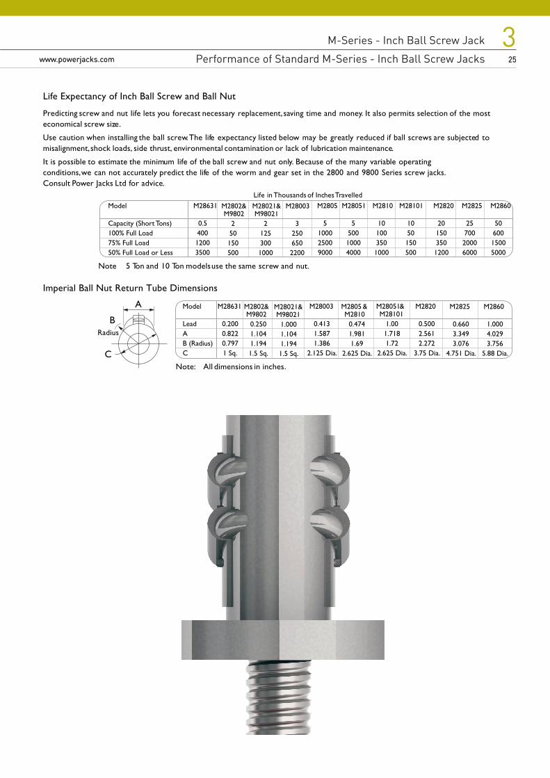
Life Expectancy of Inch Ball Screw and Ball Nut
Predicting screw and nut life lets you forecast necessary replacement, saving time and money. It also permits selection of the mosteconomical screw size.
Use caution when installing the ball screw. The life expectancy listed below may be greatly reduced if ball screws are subjected tomisalignment, shock loads, side thrust, environmental contamination or lack of lubrication maintenance.
It is possible to estimate the minimum life of the ball screw and nut only. Because of the many variable operatingconditions, we can not accurately predict the life of the worm and gear set in the 2800 and 9800 Series screw jacks. Consult Power Jacks Ltd for advice.
Life in Thousands of Inches Travelled
Note 5 Ton and 10 Ton models use the same screw and nut.
Imperial Ball Nut Return Tube Dimensions
Note: All dimensions in inches.
Radius
C
B
A
M-Series - Inch Ball Screw Jack
Inch Ball Screw Jack Dimensions26
3www.powerjacks.com26 www.powerjacks.com
Plan View
AJ
C
B
AA
H
DFG
E
AA
A
B
F
S
T
V
N
O
P
Q
R
W
X
K
L
M
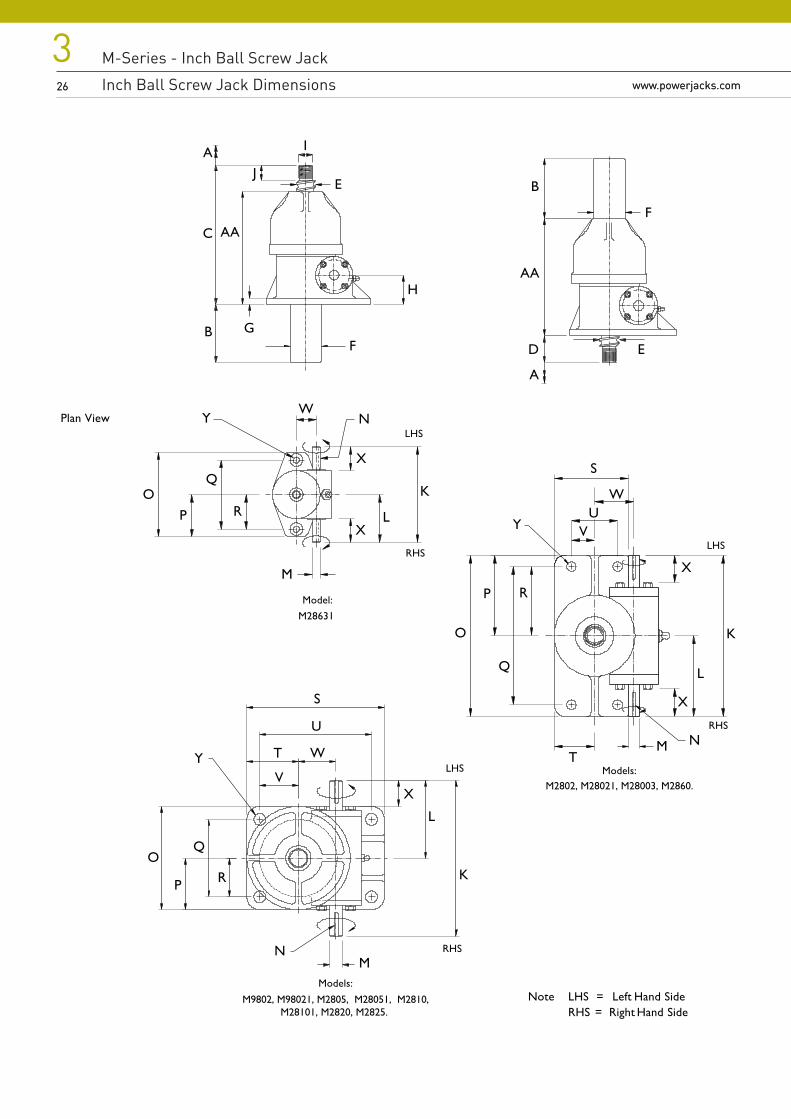
Models:
M9802, M98021, M2805, M28051, M2810,M28101, M2820, M2825.
E
X
U
Models:
S
T
V
N
O
P
Q
R
W
X
K
L
M
U
Y
NW
X
K
L
M
OP
Q
R
Y
X Y
I
Model:
M28631
RHS
LHS
Note LHS = Left Hand SideRHS = Right Hand Side
RHS
LHS
RHS
LHS
M2802, M28021, M28003, M2860.
M-Series - Inch Ball Screw Jack
Inch Ball Screw Jack Dimensions
M-Series - Inch Ball Screw Jack
Inch Ball Screw Jack Dimensionswww.powerjacks.com
327www.powerjacks.com 27
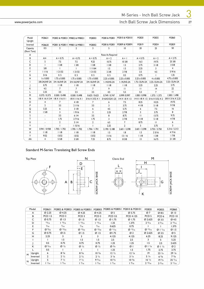
Standard M-Series Translating Ball Screw Ends
F
Top Plate Clevis End N
C
D
BA
EL
K
JI
H
G
M
SCR
EW JA
CK
BA
SE
SCR
EW JA
CK
BA
SE
M9802 & M98021
M9801 & M980112
A + 0.757.5
1 3/81
1 21/320. 5
1.75 ± 0.0053/4-16UNF-2A
1 1/87
3.50.500 / 0.498
1/8 X 1/16 X 14 1/82 1/163 1/81 9/166 1/42 7/165 1/4
1 15/161.705 / 1.702
1 1/813/325 5/8
M28003 M280 & M2801
M280 & M2801
M2810 & M28101
M2809 & M28091
M2820
M2819
M2825
M2824
M2860
M2859
M28631
M28630 M280023
A + 0.759.251 3/8
1 11/641 21/32
0. 51.75 ± 0.005
3/4-16UNF-2A1 1/8
73.5
0.625 / 0.6233/16 X 3/32 X 1
73.563
3.51.75
21
1.706 / 1.7011 1/813/327.25
5
A + 210.751 3/81.5
2 3/80. 5
2.25 ± 0.0051-14UNS-2A
1 1/89
4.50.749 / 0.747
3/16X3/32X1.2563
4.52.25
83
6.52.25
2.190 / 2.1881.5
11/168.75
10
A + 110 3/8
1.51.5
2 7/80.5
2.25 ± 0.0051-14UNS-2A
1 1/8115.5
0.999 /0.9971/4 X 1.8 X 1.5
7.53.755.752 7/88.752 7/8
72
2.601 / 2.5981.8
13 / 168 3/8
M2802 & M28021
M2801 & M280112
A + 0.757.5
1 3/81
1 21/320. 5
1.75 ± 0.0053/4-16UNF-2A
1 1/87
3.50.500 / 0.498
1/8 X 1/16 X 17
3.563
3.51.75
21
1.705 / 1.7021 1/813/325 5/8
50
A + 2.7525 3/83 5/8
45 9/161.25
4.75 ± 0.0053.25-12UN-2A
2.752211
1.500 / 1.4983/8 X 3/16 X 2.25
19.759 7/8168
9.754 7/8
63
5.316 / 5.3134 7/161 7/821 3/8
0.5
ModelUpright
Capacity(Short Tons)
Inverted
A + 151
5/81 1/165/16
1 ± 0.0033/8-24UNF-2A
0.754.52.25
0.375 / 0.3731/8 X 1/6 X 3/4
42
3.251 5/8
----
0.941 / 0.9381 1/89/32
4
Raise As Required
20
A + 0.7516.52.752.253.50.75
3.25 ± 0.0051.75-12UN-2A
2.25115.5
1.000 / 0.9981/4 X 1/8 X 1.5
8.254 1/8
6311
4 1/88.75
32.601 / 2.598
1.51 1/813
ABCDEFGHIJKLMNOPQ
VWXY
RSTU
AA
25
A + 219.753 1/8
34.51
4 ± 0.0052.25-12UN-2A
2.25147
1.375 / 1.3735/16 X 5/32 X 2
10.255 1/87.53.7513.755 1/811
3.753.755 / 3.750
2 5/161 3/816.75
Ø 2.25PCD 1.5Ø 0.75
13/16
5/16
Ø 9/32
Ø 0.752.25
10.5
Ø 5/16
0.5625
1 1/16
M
N
M2802 & M28021M28631Ø 4.25PCD 3Ø 1.51 13/16
7/16
Ø 13/32
Ø1.53
1.50.75Ø 1/2
18 5/82 1/27 1/21 7/16
M2805 & M28051 M2805 & M28051 M2810 & M28101Ø 4.25PCD 3Ø 1.51 13/16
7/16
Ø 13/32
Ø 1.53
1.50.75Ø 1/2
18 5/82 1/27 1/21 7/16
M28003Ø 4.25PCD 3Ø 1.51 13/16
7/16
Ø 13/32
Ø 1.53
1.50.75Ø 1/2
110 3/82 1/29 5/16
1 7/16
Ø 5PCD 3.5Ø 1.751.250.625Ø 11/16
Ø1.754.1252.51.25Ø 3/41.2512 1/23 1/810 3/41 7/16
Ø 5.75PCD 4.125
Ø 1.751.3750.75
Ø 13/16
Ø 24.1252.51.25Ø 11.5
12 1/83 1/410 3/81 9/16
M2820Ø 7
PCD 5Ø 2.625
2 5/16
1Ø 13/16
Ø 2.6256.25
31.5
Ø 1 1/41.7519
5 1/416 1/22 13/16
M2825Ø 8.5PCD 6Ø 3.52 5/16
1Ø 1 1/16
Ø 3.58.25
52.5
Ø 1 1/22.7523 1/46 5/819 3/43 3/16
M2860Ø 13
PCD 10Ø 4.52 13/16
1.375Ø 1.5Ø 5
9.1255.252.625Ø 23.7529 1/87 3/8
25 7/16
3 11/16
UprightInvertedUprightInverted
ABCDEFGHIJKL
Model
= =
M-Series - Inch Ball Screw Jack
Rotating Ball Screw Jack Dimensions28
3www.powerjacks.com28 www.powerjacks.com
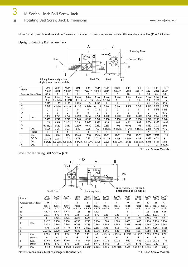
Note For all other dimensions and performance data refer to translating screw models. All dimensions in inches (1" = 25.4 mm).
Upright Rotating Ball Screw Jack
* 1" Lead Screw Models.Inverted Rotating Ball Screw Jack
Note: Dimensions subject to change without notice. * 1" Lead Screw Models.
UM 2826
25Raise+ 102.258 7/81 5/8
02.2502.2489.3952.027.375
825/326.254.751
0
UM 2821
20Raise+ 82.5
7 1/810
1.7501.7486.7061.5825.375
621/324.3753.375
0
UM 28111*
10Raise+ 51
5 5/800
1.0000.9983.651.02
4 15/164
17/324 1/8
2.25 SQR.0
3Raise
+ 3.751.1254 1/167/16
00.7500.7483.3950.8324.24
25/643 7/162.125
0
UM9803
KUM2806
KUM28004
2Raise
+ 3 1/161.1254 1/16
00
0.7500.7482 3/80.6303.25
417/642.75
1.5 SQR.0
5Raise
+ 4 5/81
5 1/400
1.0000.9984.330.895
4 15/164
17/324 1/162.625
0
5Raise+ 41
5 1/400
1.0000.9983.651.02
4 15/164
17/324 1/8
2.25 SQR.0
UM 2861*
50Raise+ 153.25
10 7/81 1/80.753.2503.24812.6252.029.75
61 1/32
85.88
5.5625
UM 2811
10Raise+ 61
5 5/800
1.0000.9984.330.895
4 15/164
17/324 1/162.625
0
2Raise
+ 3 11/161.1254 1/16
00
0.7500.7483 1/320.6303.25
417/642.75
1.5 SQR.0
UM28632
KUM28031*
0.25Raise+ 2
0.6252 3/8
00
0.4370.4351.75
0.531252.625
417/642 3/321 SQR.
0
KUM2803
2Raise
+ 3 1/161.1254 1/16
00
0.7500.7482 3/80.6303.25
417/642.75
1.5 SQR.0
Model
Capacity (Short Tons)
A
BCC’D
E Dia.
FGH Dia.
HolesI Dia.
P.C.DJ Dia.K Dia.
UM98031*
2Raise
+ 3 11/161.1254 1/16
00
0.7500.7483 1/320.6303.25
417/642.75
1.5 SQR.0
A
I
C
B
H
FG
E
J
D
K
Pilot
ShellShell Cap
Mounting Plate
Bottom PipeLiftingNut
KDM 2826
25Raise+ 102.258.8752.5
2.2502.2489.3952.027.375
825/326.254.751
KDM 2821
20Raise+ 82.5
7.1251.6251.7501.7486.7061.5825.375
621/324.3753.375
KDM 28111*
10Raise+ 515
1.1251.0000.9983.651.02
4 15/164
17/324 1/8
2.25 SQR.
KDM28004
3Raise
+ 3.751.1253.75
10.7500.7483.3950.8324.24
25/643 7/162.125
KDM9803
2Raise
+ 3 1/61.1253.750.6250.7500.7482 3/80.6303.25
417/642.75
1.5 SQR.
KDM28006
5Raise
+ 4 5/81
5.250.751.0000.9984.330.895
4 15/164
17/324 1/162.625
KDM 28061*
5Raise+ 41
5.250.751.0000.9983.651.02
4 15/164
17/324 1/8
2.25 SQR.
KDM 2861*
50Raise+ 153.25112.5
3.2503.24812.6252.029.75
61 1/32
85.88
KDM 2811
10Raise+ 615
1.1251.0000.9984.330.895
4 15/164
17/324 1/162.625
KDM 28031*
2Raise
+ 3 5/81.1253.750.6250.7500.7483 1/320.6303.25
417/642.75
1.5 SQR.
DM 286320.25Raise
+ 2 3/80.6252.375
00.4370.4351.75
0.531252.625
417/642 3/321 SQR.
KDM2803
2Raise+ 3
1.1253.750.6250.7500.7482 3/80.6303.25
417/642.75
1.5 SQR.
Model
Capacity (Short Tons)
A
BCD
F Dia.
GHI Dia.
HolesJ Dia.
P.C.DK Dia.
KDM98031*
2Raise
+ 3 5/81.1253.750.6250.7500.7483 1/320.6303.25
417/642.75
1.5 SQR.
Lifting Screw - right hand,single thread on all models
A
I
C B
HK
G
J
D
Pilot
Shell
Shell Cap Mounting BaseLifting Screw - right hand,single thread on all models
C’
LiftingNut
F
KUM28061*
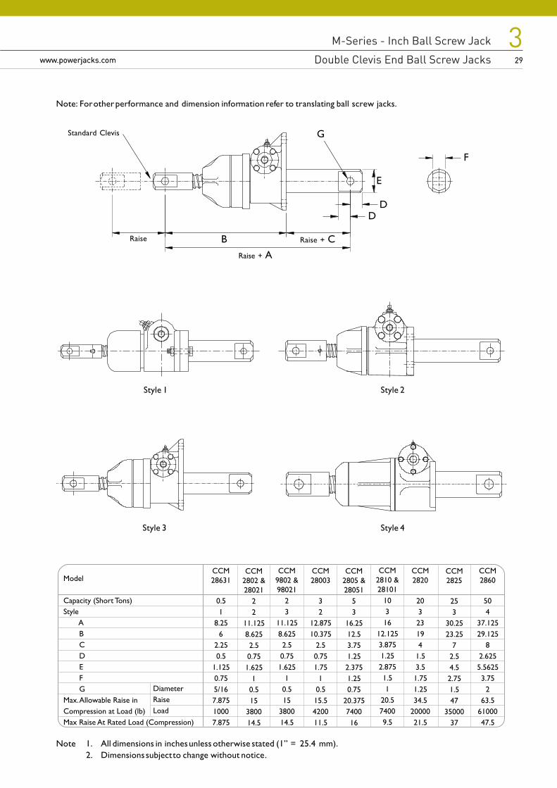
M-Series - Inch Ball Screw Jack
Rotating Ball Screw Jack Dimensions
M-Series - Inch Ball Screw Jack
Double Clevis End Ball Screw Jackswww.powerjacks.com
329www.powerjacks.com 29
Note: For other performance and dimension information refer to translating ball screw jacks.
Note 1. All dimensions in inches unless otherwise stated (1” = 25.4 mm).2. Dimensions subject to change without notice.
Style 1
B
Style 2
Raise
Raise + A
Raise + C
D
F
Standard Clevis
Model
Capacity (Short Tons)Style
ABCDEFG
Max. Allowable Raise inCompression at Load (lb)Max Raise At Rated Load (Compression)
CCM9802 &98021
23
11.1258.6252.50.751.625
10.515
380014.5
CCM2860
504
37.12529.125
82.6255.56253.75
263.5
6100047.5
CCM2802 &28021
22
11.1258.6252.50.751.625
10.515
380014.5
CCM28631
0.51
8.256
2.250.5
1.1250.755/167.87510007.875
CCM28003
32
12.87510.375
2.50.751.75
10.515.5420011.5
CCM2805 &28051
53
16.2512.53.751.252.3751.250.75
20.375740016
CCM2810 &28101
10316
12.1253.8751.252.8751.51
20.574009.5
CCM2820
20323194
1.53.51.751.2534.5
2000021.5
CCM2825
253
30.2523.25
72.54.52.751.547
3500037
DiameterRaiseLoad
Style 3 Style 4
D
E
G
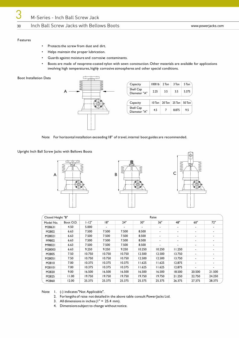
M-Series - Inch Ball Screw Jack
Inch Ball Screw Jacks with Bellows Boots30
3www.powerjacks.com30 www.powerjacks.com
Features
• Protects the screw from dust and dirt.
• Helps maintain the proper lubrication.
• Guards against moisture and corrosive contaminants.
• Boots are made of neoprene-coated nylon with sewn construction. Other materials are available for applicationsinvolving high temperatures, highly corrosive atmospheres and other special conditions.
Boot Installation Data
Note For horizontal installation exceeding 18" of travel, internal boot guides are recommended.
Upright Inch Ball Screw Jacks with Bellows Boots
Note 1. (-) indicates "Not Applicable".2. For lengths of raise not detailed in the above table consult Power Jacks Ltd.3. All dimensions in inches (1" = 25.4 mm).4. Dimensions subject to change without notice.
Capacity
Shell CapDiameter "A"
10 Ton
4.5
20 Ton
7
25 Ton
8.875
50 Ton
9.5
Capacity
Shell CapDiameter "A"
1000 lb
2.25
2 Ton
3.5
3 Ton
3.5
5 Ton
5.375A
72"----------
21.50024.25028.375
18"-
7.5007.5007.5007.5009.25010.75010.75010.37510.37516.50019.75025.375
1-12"5.0007.5007.5007.5007.5009.25010.75010.75010.37510.37516.50019.75025.375
60"----------
20.50022.75027.375
48"-----
11.25013.75013.75012.87512.87518.50021.25026.375
Boot O.D.4.506.636.636.636.636.637.507.507.007.009.0011.0012.00
Model No.M28631M2802M28021M9802M98021M28003M2805M28051M2810M28101M2820M2825M2860
Closed Height "B"
24"-
7.5007.5007.5007.5009.25010.75010.75010.37510.37516.50019.75025.375
30"-
8.5008.5008.5008.50010.25012.50012.50011.62511.62516.50019.75025.375
36"-----
10.25012.50012.50011.62511.62516.50019.75025.375
Raise
A B C
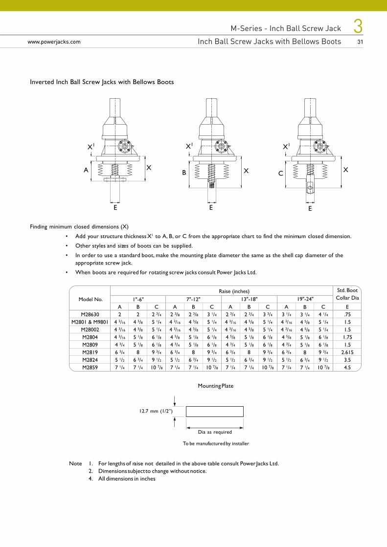
M-Series - Inch Ball Screw Jack
Inch Ball Screw Jacks with Bellows Boots
M-Series - Inch Ball Screw Jack
Inch Ball Screw Jacks with Bellows Bootswww.powerjacks.com
331www.powerjacks.com 31
Finding minimum closed dimensions (X)
• Add your structure thickness X1 to A, B, or C from the appropriate chart to find the minimum closed dimension.
• Other styles and sizes of boots can be supplied.
• In order to use a standard boot, make the mounting plate diameter the same as the shell cap diameter of theappropriate screw jack.
• When boots are required for rotating screw jacks consult Power Jacks Ltd.
A B
X1
E
X1
C
X1
X X X
Dia as required
Mounting Plate
12.7 mm (1/2”)
To be manufactured by installer
Note 1. For lengths of raise not detailed in the above table consult Power Jacks Ltd.2. Dimensions subject to change without notice.4. All dimensions in inches.
EE
C4 1/45 1/45 1/46 1/86 1/89 3/49 1/210 7/8
19"-24"Model No.
M28630M2801 & M9801
M28002M2804M2809M2819M2824M2859
Raise (inches)
A2
4 3/16
4 3/16
4 3/16
4 3/46 3/45 1/27 1/4
B2
4 5/84 5/85 1/85 1/8
86 3/47 1/4
C2 3/45 1/45 1/46 1/86 1/89 3/49 1/210 7/8
A2 3/84 3/16
4 3/16
4 5/84 3/46 3/45 1/27 1/4
B2 3/84 5/84 5/85 1/85 1/8
86 3/47 1/4
C3 1/45 1/45 1/46 1/86 1/89 3/49 1/210 7/8
A2 3/44 3/16
4 3/16
4 5/84 3/46 3/45 1/27 1/4
B2 3/44 5/84 5/85 1/85 1/8
86 3/47 1/4
1"-6" 7"-12"C
3 3/45 1/45 1/46 1/86 1/89 3/49 1/210 7/8
A3 1/44 3/16
4 3/16
4 5/84 3/46 3/45 1/27 1/4
13"-18"B
3 1/44 5/84 5/85 1/85 1/8
86 3/47 1/4
E.751.51.51.751.5
2.6153.54.5
Std. BootCollar Dia
Inverted Inch Ball Screw Jacks with Bellows Boots
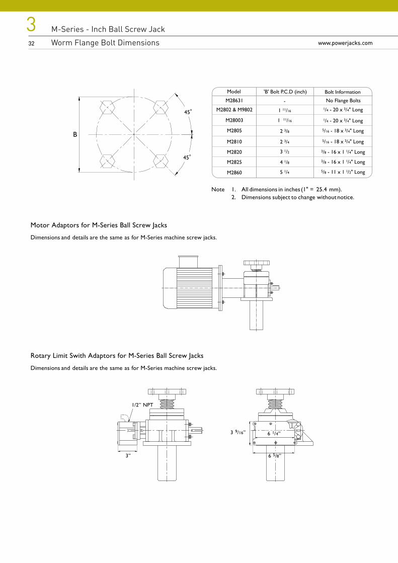
M-Series - Inch Ball Screw Jack
Worm Flange Bolt Dimensions32
3www.powerjacks.com32 www.powerjacks.com
45o
45o
B
Model 'B' Bolt P.C.D (inch)
1 11/16
1 11/16
2 3/8
2 3/4
3 1/2
4 1/8
5 1/4
-
Bolt Information
No Flange Bolts1/4 - 20 x 3/4" Long
1/4 - 20 x 3/4" Long
5/16 - 18 x 3/4" Long
5/16 - 18 x 3/4" Long
3/8 - 16 x 1 1/4" Long
5/8 - 11 x 1 1/2" Long
3/8 - 16 x 1 1/4" Long
M28631
M2802 & M9802
M28003
M2805
M2810
M2820
M2825
M2860
Motor Adaptors for M-Series Ball Screw Jacks
Dimensions and details are the same as for M-Series machine screw jacks.
Rotary Limit Swith Adaptors for M-Series Ball Screw Jacks
Dimensions and details are the same as for M-Series machine screw jacks.
3”
3 9/16”
6 5/8”
6 1/4”
1/2” NPT
Note 1. All dimensions in inches (1" = 25.4 mm).2. Dimensions subject to change without notice.
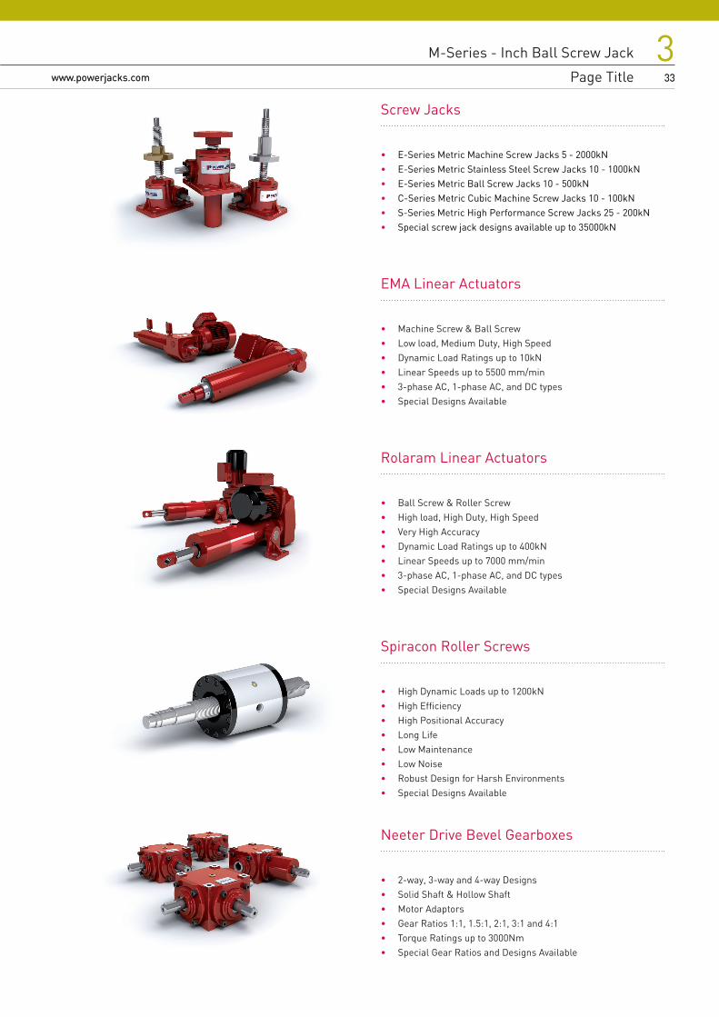
M-Series - Inch Ball Screw Jack
Worm Flange Bolt Dimensions
M-Series - Inch Ball Screw Jack
Page Titlewww.powerjacks.com
333www.powerjacks.com 33
Screw Jacks
• E-Series Metric Machine Screw Jacks 5 - 2000kN• E-Series Metric Stainless Steel Screw Jacks 10 - 1000kN• E-Series Metric Ball Screw Jacks 10 - 500kN• C-Series Metric Cubic Machine Screw Jacks 10 - 100kN• S-Series Metric High Performance Screw Jacks 25 - 200kN• Special screw jack designs available up to 35000kN
EMA Linear Actuators
• Machine Screw & Ball Screw• Low load, Medium Duty, High Speed• Dynamic Load Ratings up to 10kN• Linear Speeds up to 5500 mm/min• 3-phase AC, 1-phase AC, and DC types• Special Designs Available
Rolaram Linear Actuators
• Ball Screw & Roller Screw• High load, High Duty, High Speed• Very High Accuracy• Dynamic Load Ratings up to 400kN• Linear Speeds up to 7000 mm/min• 3-phase AC, 1-phase AC, and DC types• Special Designs Available
Spiracon Roller Screws
• High Dynamic Loads up to 1200kN• High Efficiency• High Positional Accuracy• Long Life• Low Maintenance• Low Noise• Robust Design for Harsh Environments• Special Designs Available
Neeter Drive Bevel Gearboxes
• 2-way, 3-way and 4-way Designs• Solid Shaft & Hollow Shaft• Motor Adaptors• Gear Ratios 1:1, 1.5:1, 2:1, 3:1 and 4:1• Torque Ratings up to 3000Nm• Special Gear Ratios and Designs Available
Power Jacks Ltd Balmacassie Commercial Park Ellon, AB41 8BX Scotland (UK) Tel: +44 (0)1358 285100
All information in this document is subject to change without notice. All rights reserved by Power Jacks Limited. May not be copied in whole or in part. ©Power Jacks Limited 2015, Aberdeenshire, Scotland, United Kingdom.
Registered
FPAL
OH 623565
PJ-SJB-M-EN-01
www.powerjacks.com [email protected]
Lifting & Positioning Solutions Power Jacks are specialist industrial engineers providingdesign, manufacturing and services of quality industrial lifting, positioning and load monitoring equipment.Our products are supplied globally across many sectors including Industrial Automation, Energy, Transport, Defence and Civil.


