IEEE TRANSACTIONS ON MAGNETICS, VOL. 49, NO. 11, NOVEMBER 2013 5489
Magnetic Nanofluid Applications in Electrical EngineeringLucian Pîslaru-Dănescu , Alexandru M. Morega , Gabriela Telipan , Mihaela Morega ,
Jean Bogdan Dumitru , and Virgil Marinescu
National Institute for Electrical Engineering ICPE-CA, Bucharest, RomaniaFaculty of Electrical Engineering, University POLITEHNICA of Bucharest, Romania
“Gh. Mihoc-C. Iacob” Institute of Statistical Mathematics and Applied Mathematics, Romanian Academy
This paper presents a superparamagnetic nanofluid (SMP-NF) and three of its applications. The SPM-NF particles were suspended inoleic acid as surfactant, and then dispersed in UTR 40 transformer oil (TO). The average particle size obtained from X-ray diffractionis 14 nm, and from scanning electron microscopy is between 10 and 30 nm. The magnetic measurements for the oleic-oil transformeracid-magnetite nanoparticles of 27 nm diameter in size and particle density system provide for specificsaturation magnetization, . The volume fraction is 1.1% and the magnetization is 62 Gs. The SPM-NF may be designed to be usedeither as coolant or as magnetic medium in three electrotechnic devices: a power electric transformer TMOf 2–36 kV–40 kVA, at 50Hz, a microactuator that implements the pulse width modulation (PWM) principle, and in miniature planar spiral transformers, forgalvanic separation or step-up/step-down conversion. The paper presents experimental and numerical simulation results that confirmthat the SPM-NF usage open new venues in optimizing conventional electrotechnic constructions or to design novel devices.
Index Terms—Colloidal magnetic nanoparticles, electrical transformer, magnetic nanofluid coolant, magnetic properties, mi-croactuator, miniature planar spiral transformer, numerical simulation, pulse width modulation, scanning electron microscopy.
I. INTRODUCTION
A ferrofluid consists typically of colloidal ferromagneticparticles such as Co, FePt, , ,
(approximately 3–15 nm in size), dispersed in a carrier fluid[1]–[3]. Among these, magnetite has attracted muchinterest in recent years due, mainly, to two properties: first, itis expected to be half-metallic ferromagnetic at room temper-ature, possessing 100% spin polarized charge carriers at theFermi level and second, it exhibits a metal-to-insulatortype transition, known as the Verwey transition [4]. This is aspontaneous cross-correlated change in both lattice symmetryand electrical conductivity at a critical temperature that, forstoichiometric magnetite, is 120 K, [5]. The structure of mag-netite consists of cubic inverse spinel structure with closepacked oxygens and Fe cations occupying interstitial tetra-hedral and octahedral site, [5]. The magnetite unit cell has a8.3963 lattice constant and can be represented by the formula
, where A and B indicate tetrahe-dral and octahedral positioning, respectively. The electronscan hop between and ions in the octahedral sitesat room temperature, rendering magnetite an important classof half-metallic materials [2], [5]. The most common methodsfor the synthesis of iron oxide nanoparticles in aqueous sus-pension are based either on the wet chemical co-precipitationof ferrous and ferric ions with ammonia, or sodium hydroxidein aqueous solution or in microemulsion [7], or on the partialoxidation of ferrous hydroxide gels. Other methods include,e.g., hydrothermal spray pyrolysis, ion exchange, electro-pre-cipitation of nanoparticles in ethanol, sonochemicaland electrochemical methods, sol-gel reaction, decompositionorganometallic precursors and polyol method [7]–[11]. Some
Manuscript received January 29, 2013; revised April 24, 2013 and June 14,2013; accepted June 19, 2013. Date of publication June 28, 2013; date of cur-rent version October 21, 2013. Corresponding author: A. M. Morega (e-mail:[email protected]).Digital Object Identifier 10.1109/TMAG.2013.2271607
of the common problems of magnetic nanoparticles are theirtendency to agglomerate once formed and their chemical insta-bility with respect to oxidation in air. Magnetic nanoparticleswere coated with surfactant to overcome these problems [7].In order to obtain well disperse magnetic nanoparticles, eithersurfactants such dextran, polyvinylalcohol (PVA), oleic acid,can be added in the reaction media, or the particles can becoated in a subsequent step. The surfactants act as protectingagent for controlling particle size and stabilizing the colloidaldispersions [12].Due to their small size particles and superparamagnetic
(SPM) properties, the ferrofluids have been extensively usedin biomedical applications: as delivery system (for drugs,genes, radionuclides), as contrast agents in magnetic resonanceimaging, for in vitro applications in medical diagnostics suchas research in genetics, in clinical studies of cancer therapy inveterinary and human medicine [7], [13], [14]. Ferrofluids arealso used in technical applications: efficient electrical motors,bearings and dampers, in cars and other machines, magneticrecording industry, magneto-optic recording devices, highsensitivity optical actuators, magnetic fluid linear lab-on-a-chipmicrofluidics, pumps, and giant magnetoresistive devices[15]–[20].This paper presents, briefly, the preparation, properties, and
characterization of a superparamagnetic nanofluid (SPM-NF)based on colloidal nanoparticles of and transformeroil (TO). This nanofluid, whose properties (magnetic, electric,heat transfer) may be tailored to meet specific requirements,is an enabling working substance for many electrotechnicalconstructions. Here we are concerned with an electrical powertransformer, a microactuator and miniature planar spiral powertransformers.
II. THE SUPERPARAMAGNETIC NANOFLUID
We prepared a superparamagnetic nanofluid (SPM-NF) withnanoparticles, of 0.914 , 1.1% volume fraction,
and 62 Gs magnetization by the coprecipitation method [21]using a molar ratio and alkaline medium
5490 IEEE TRANSACTIONS ON MAGNETICS, VOL. 49, NO. 11, NOVEMBER 2013
Fig. 1. The XRD pattern of the sample of nanoparticles.
NaOH 10%. A small amount of powder was analyzed for struc-tural properties. Another amount of powder was treated with 2ml acid oleic, as surfactant. The mixture was dispersed in 50ml of UTR 40 transformer oil (TO), under strong stirring for 20hours to obtain the SPM-NF.The nanoparticles were characterized by X-ray
diffraction (XRD) radiation , 40KV/40 mA, filter of Ni, in the range 25–70 , a step of0.04 and measuring time on point: 1 s. The diffraction patternwas obtained using a D8 ADVANCE type X Bruker-AXSdiffractometer.The morphology of the sample was studied through SEM,
using a Carl Zeiss SMT FESEM-FIB Auriger type scanner.Elemental analysis (energy-dispersive X-ray spectroscopyEDX) was performed with an energy dispersive probe of IncaEnergy 250 type Oxford Instruments LTD England coupledto SEM. The magnetic hysteresis loop and first magnetizationcurves were drawn with a LakeShore 7300 vibrating samplemagnetometer.The purity of the prepared colloidal magnetic
nanoparticles was examined by X-ray diffraction, Fig. 1. TheXRD spectrum exhibits peaks corresponding to , markedwith their indices (220), (311), (400), (422), (511), and (440),similar to those reported for nanoparticles [1], [2].The lattice constant of extracted from the XRD data
is , in good agreement with literature data(JCPDS file no. 19–629). The spinel diffraction pattern is con-firmed from the given hkl indices. The medium crystallites sizecalculated with Scherrer formula for the (311) peak formula was14 nm.The topology of the powder was analyzed by scan-
ning electron microscopy. A crystalline structure of the materialwas found which is composed of crystallites of average sizes be-tween 10 and 30 nm (Fig. 2) in good agreement with the diffrac-tion analysis.The elemental analysis shows that the resulting black
powder contains 70.14% Fe, 24.96% O, 4.16% C, and 0.74%Cl (Table I), the high percentage of oxygen is related to itsexistence in the iron oxide. The content of C and Cl results inlittle impurities.The initial susceptibility , the saturation magnetization,, and the magnetic field , the relation are
determined by representing the experimental data (Fig. 3).
Fig. 2. The SEM image for the Fe O powder.
TABLE IANALYSIS DATA FOR NANOPARTICLES
Fig. 3. The curve of first magnetization, .
The magnetic nanoparticles are assumed spherical, and theiraverage diameter is determined from the ambient temperaturemagnetization curve. For , .The magneto-granulometric analysis was used to determine
the distribution parameters , , and the mean magnetic di-ameter, [2], [20]. The parameter deviation of in
of the log-normal distribution is calculated as
(1)
where and (Fig. 4). The diameterof the nanoparticles is given by [21], [22],
(2)
PÎSLARU-DĂNESCU et al.: MAGNETIC NANOFLUID APPLICATIONS IN ELECTRICAL ENGINEERING 5491
Fig. 4. The curve.
Here is the minimum diameter
(3)
Here is Boltzmann constant, isthe temperature (293.15 K), is the freespace permeability, and is the saturationmagnetization of magnetite [2].Finally, the particle density is
(4)
The calculated average particle diameter of the SPM-NF is28.65 nm, in good agreement with the diffraction analysis.
III. APPLICATIONS OF THE SPM-NF
Earlier research has shown that the replacement of the clas-sical TO by ferrofluid improves the transformer thermal anddielectric properties. Ferrofluids provide also the increase ofthe capacity of the transformer to sustain over-voltages, andto better withstand degradation due to humidity, in time [22],as compared to the classic oils. Thus, transformers with higherefficiency and reduced dimensions, extended life duration andloading capacity may be designed.
A. The TMOf 2–36 kV–40 kVA Electrical Transformer
Thermal stability of power transformers is a general concernand has direct consequences in their design that has to providesolutions for adequate cooling conditions. The usage of TO ascoolant is the classical solution to the problem, and it surelyrepresents a standard for this issue. However, when compact,smaller units are desired better working fluids have to be con-sidered, and this was the object of our research.To investigate the feasibility and performance of a SPM-NF
cooled transformer we designed, fabricated, and tested a pro-totype (Fig. 6), which had to comply with several design con-straints such as:1) reduced weight and size as compared to current powertransformers with the same rated voltage and power;
Fig. 5. The prototype [26].
Fig. 6. Aggregate active parts.
2) less active materials (copper, magnetic steel sheet) throughan adequate design of the magnetic circuit.
3) an as small as possible amount of SPM-NF, which is moreexpensive than TO.
The single phased, medium voltagetransformer prototype (either step-up or step-down), operatingat 50 Hz, may use either TO (CEI 60296) or SMP-NF (Fig. 5).Heat transfer to ambient is by the natural convection. The caseis air-proof soldered and an elastic membrane is provided tocompensate for the possible thermal expansion of the coolant.The active part, consisting of hemagnetic core with high voltage(HV) and low voltage (LV) windings is fastened to the metallid with their axes in vertical position, the most advantageousposition for enhancing heat transfer, Fig. 6. The HV winding(3) has an insulated terminal, while the other one is connected toground. The vertical channel between the windings is 0.22 mmwide. The LV winding (2) is a copper foil 0.2 mm thick, suchthat each layer has a single winding. The disc assembly (4) andthe tube (5) add to the insulation scheme. A clamp system (1) isused to tighten the four cores of the magnetic circuit.Mathematical modeling and numerical simulations were used
in the design phase of the prototype. The mathematical model ofthe magnetic field and the Newtonian, laminar, thermal flow isdescribed by the following partial differential equations (PDEs)[24]
5492 IEEE TRANSACTIONS ON MAGNETICS, VOL. 49, NO. 11, NOVEMBER 2013
Fig. 7. Temperature (contour lines, gray map) and the natural flow (stream-lines, arrows)—transformer oil (left) and SPM-NF (right).
Magnetic field (quasi-steady, harmonic)
(5)
Momentum balance (Navier-Stokes)
(6)
Mass conservation (incompressible flow)
(7)
Here , is the magnetic vector potential,the external current density (in the coils), [S/m]
the electrical conductivity, theelectrical permittivity of the free space, the relative permit-tivity, the magnetic permeability of freespace, [m/s] the velocity, [s] the time, the pressure,
the thermal force, the mass den-sity, the gravity (downwards, vertical direction), and
the kinematic viscosity.Magnetic forces, , which occur in
the SPM-NF, may be significant in regions of higher gradientmagnetic field. [A/m] is the magnetic field strength.The constitutive law for the SPM-NF is
(8)
where [T] is magnetic flux density. The SPM-NF magneti-zation is isotropic, approximated through ,where and are empiricalconstants [25].The boundary conditions that close the magnetic field and
flow models are: magnetic insulation for the solid walls andsymmetry planes ( , where is the outward pointing
Fig. 8. Temperature field and fluid flow in the transformer with SPM-NF.(a) Isotherms and natural flow field. (b) Flow by massless particle tracing.
normal) for the magnetic field problem, no-slip (zero) velocityat solid walls, and zero normal velocity at symmetry planes.The heat transfer is described by the energy equation [24]
(9)
where is specific heat, is thermalconductivity, and is the heat source (Joule effect).It should be noted that the convective term in (9) makes thedifference between TO and SPM-NF.The boundary conditions for the heat transfer problem are:
specified temperature for the case bottom andnatural convection at thecase lateral wall and top cover.The magnetic field problem is solved first. Its results are the
magnetization body forces within the magnetic fluid, and theheat sources (Joule effect) in the active parts of the transformer.The different time-scales of the magnetic field (fast phenom-enon) and the heat transfer (slow phenomenon) suggest thattheir coupling may be adequately treated in the effective values(RMS) sense of the coupling quantities, where the (Joule) powerdensity is the heat source and the magnetic body forces add tothe momentum balance (6), (7). A scale analysis similar to thatpresented in [29] may confirm.Simpler, 2D (Fig. 7), and more complex, 3D (Fig. 8) models
were used to evaluate the magnetic field and thermal flow ofthe coolant. These models were solved numerically by the fi-nite element method (FEM) [23], [27]–[29].When the coolant isSPM-NF magnetic forces add to the thermal (buoyancy) forces.Comparing the two cooling options, the magnetic fluid may dobetter in cooling the transformer of vertical design. This essen-tially means a lower hot spot temperature level, by approxi-mately 20 degrees (Fig. 7), and a more even temperature dis-tribution [26].Fig. 8 shows the temperature field and the natural flow of the
SPM-NF in the 3D model. The hot spot temperature is lowerby 10 degrees, and a more uniform temperature distribution isnoticed. Furthermore, particles that initially reside in narrow,
PÎSLARU-DĂNESCU et al.: MAGNETIC NANOFLUID APPLICATIONS IN ELECTRICAL ENGINEERING 5493
Fig. 9. The microactuator—experimental layout (left) and cell (right). Somefluid is removed to expose the coils but the wavy surface is still apparent [29].
Fig. 10. The output PWM pulse form for a pulse duty factor, , of 14%.
less accessible spaces, e.g. the channel between the wind-ings, are conveyed by the natural flow, eventually, to the case(Fig. 8(b)). This is good news since heat is transported to theambient, preventing local overheating. In fact, the hot spotregion is recorded at the bottom of the unit, and not in thechannel between windings.Numerical simulation results showed how the particular ori-
entation of the magnetizing forces and the thermal forces mightconcur in the heat transfer. We found it important to evaluatethese forces in the design phase of the prototype in order to op-timize the unit. Consequently, the prototype was built in verticalconfiguration, and this is a meaningful result obtained by numer-ical modeling. Heat transfer experiments and the validation ofthe numerical simulation results may be found in [26].
B. The Microactuator
The SPM-NF is used in a microactuator (Fig. 9) based on thepulse width modulation (PWM) principle: a short duration pulsemeans lower current through the windings of the microactuatorand a long duration pulse means higher current.Fig. 10 shows the PWM output of rectangular form with a
duty factor of [21]. The main characteristics of thewaveforms are: counter phase, rectangular form, variable fre-quency range, – , for – and a max-imum amplitude of . When the voltage appliedto the power stage has for a constant, fixedfrequency, the microactuator works in a “linear” mode.Fig. 11 shows the diagram of the electronic source used for
the activation the microactuator. The PWM generator powersthe windings, and .The magnetic fluid motion due to the magnetization forces
depends mainly on the pulse duty factor, , of the voltage
Fig. 11. Schematic diagram of the generator that drives the actuator [21].
Fig. 12. Velocity field (arrows and gray map) and magnetic flux density(streamlines) when both coils are on. Deformation is amplified 30 times forbetter viewing.
applied to the coils [16]. The RMS value of the current throughthe coils and , for a fixed frequency of the PWM voltage,depends mainly on the pulse duty factor.To overcome the difficulties related to the 3D structure of the
microactuator and to the unsteady working conditions, whilekeeping the numerical model within convenient software andhardware limits we use symmetry and assume that the coils arecompletely immersed in the magnetic fluid, deep enough suchthat the waves produced by the magnetic forces are of low am-plitude. The mathematical model for the magnetic field and therelated forced flow within the magnetic fluid is (5)–(9). Theboundary condition on the free surface is
(10)
Here is the unity matrix and the transposition operator.Numerical simulation results are found in [29].Fig. 12 shows the magnetic flux density (streamlines), the
magnetic body forces (gray map and arrows), and the wavy freesurface for a specific moment. By symmetry reason the com-putational domain is reduced to half. The wavy surface mapsthe regions of higher magnetic field gradient in response to themagnetic body forces triggered by the electrical currents in thecoils as expected (Fig. 10).
C. Miniature Planar Spiral Power Transformers
Power supply energy harvesting sources (EHS) built in microelectro-mechanical systems (MEMS) technologies with minia-ture harvesting device aimed to scavenge energy from artificial
5494 IEEE TRANSACTIONS ON MAGNETICS, VOL. 49, NO. 11, NOVEMBER 2013
Fig. 13. A notional 1:1 MPST with ferrite/SPM-NF core.
Fig. 14. Magnetic flux density (tubes) for the fluid cored MPST. The electricpotential (surface gray map) is plotted to outline the windings.
light for powering wireless sensor nodes have recently receivedmuch attention [30]–[32].A key component is a miniature planar spiral transformer
(MPST) used in power supplies where slim design is crucial[33]. The planar structure improves cooling while providing alow profile. It was suggested recently that nanofluids might beused as magnetic core for the MPST [34].Along this line, a notional 1:1MPST (40:40 turns, the core di-
mensions are ) with SPM-NF core(Fig. 13) was proposed for galvanic separation. SPM-NF fills inthe spacing between the windings (40 turns each), which—byMEMS reasons—have square turns. The stationary magneticfield and the fluid core flow are described through the stationaryforms of (5)–(8). The field current is continuous,1 the result ofa separate DC problem. Magnetic insulation condition is setallover the outer surface. The model was solved by FEM tech-nique [27], [35].Fig. 14 shows the magnetic flux density through flux tubes.
Their color and size are proportional to the magnetic flux den-sity. The windings are evidenced by the electric potential (sur-face color maps). All parts are removed for better viewing. Thispowering scheme is used to compute the mutual inductancewhen the self-inductances are known [35].Under nominal working conditions (compensated amper-
turns, differential fascicular magnetic fluxes) the symmetry ofthe design (magnetic core, windings) and that of the magnetic
1The applied voltage leads to a current density of 1 in the coils.
Fig. 15. Flow field through stream tubes, whose colors and sizes are propor-tional to the velocity [35]. The velocities are of the order . Thepressure gradient is of the order . (a) Additional fascicular mag-netic fluxes. (b) Opposite magnetic fluxes. (c) Additional magnetic fluxes.
field (hence, magnetic forces) suggest symmetry about the hor-izontal symmetry plane in the flow pattern. The flow problemmay be reduced then to half, with significant gain in storage andCPU time.The boundary conditions are no slip (zero velocity) at the
solid walls, and symmetry (slip) at the symmetry plane. Whenthe electrical currents have the same orientation (additional fas-cicular magnetic fluxes) symmetry is lost, and the flow problemis solved in the entire volume of the core.The flow pattern is highly sensitive to the powering scheme:
the electrical currents in the coils produce the magnetic field,which is responsible for the magnetic forces (Fig. 15).The effect of the spiral windings is also noticeable. Seen from
above, the flow pattern suggests only some centro-symmetryabout the vertical axis but, although the flow is rather regular,no other symmetry is apparent.Even though in this limit the magnetic force in vertical
direction was averaged over the core height, to reducethe computational effort, the three dimensionally organized,merging flow cells are apparent. This spatial flow is goodnews because, although the SPM-NF is a colloidal mixture,magnetic mixing contributes to its continuous homogenizationby magnetic stirring.Another concern might be the thermally produced flow. We
found that it is not the case because the fluid core becomes al-most isothermal. MPST positioning with respect to gravity di-rection is a key term in any buoyancy driven flow, but if tem-perature gradients are negligible small then thermal flows do notset in.Self-inductances (Table II) are calculated through
(11)
PÎSLARU-DĂNESCU et al.: MAGNETIC NANOFLUID APPLICATIONS IN ELECTRICAL ENGINEERING 5495
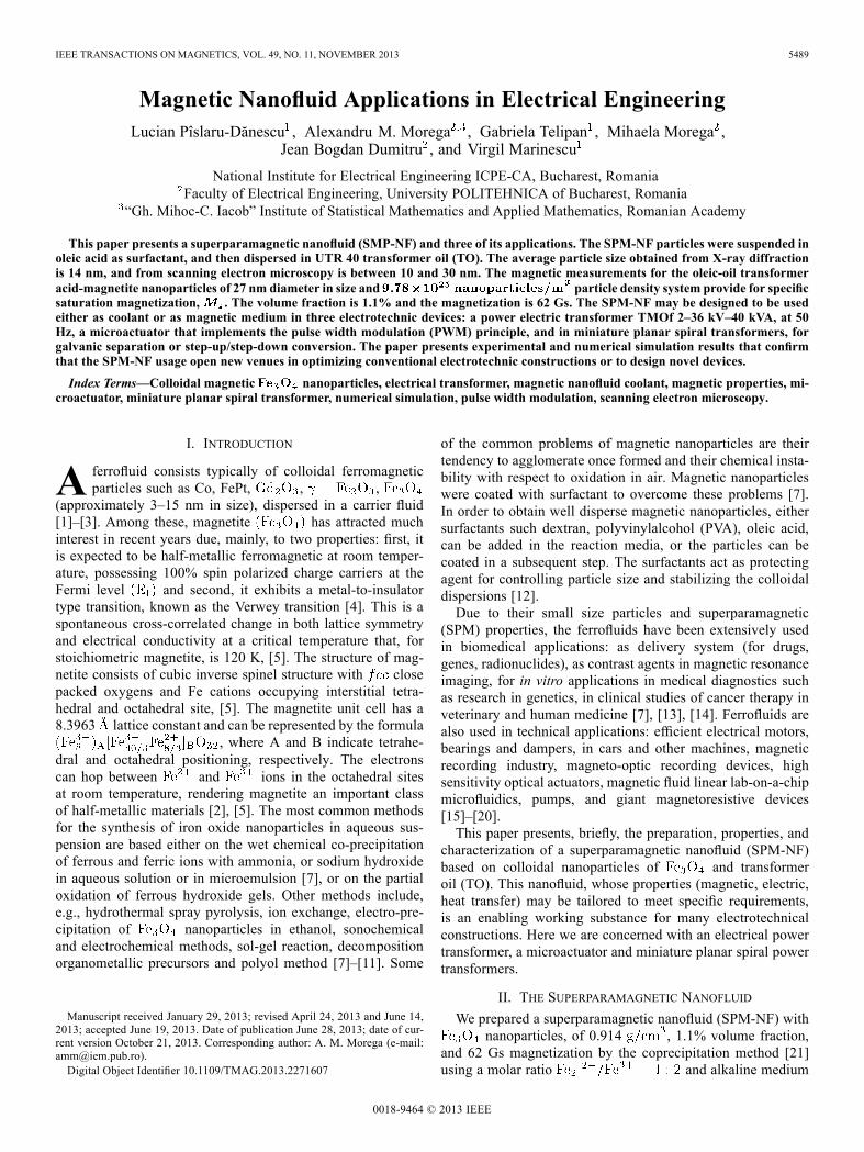
TABLE IILUMPED PARAMETERS OF THE MPST
Fig. 16. A notional step-up/step down, 2:1 MPST with ferrite/SPM-NF core.The computational domain is 1/8 of the actual size.
Here “i” denotes either primary or secondarywinding, is the magnetic energy
density when the winding “i” is fed by the current and theother winding is open; is the MPST volume. The coilsare powered in turn to calculate and respectively.Higher values for may be obtained by reducing the core
height. Sensitivity analysis of the lumped parameters with re-spect to the core height and its magnetic properties (either fer-rite or SPM-NF) are the object of an undergoing research.The capacitance of the MPST for separation (Table II) is
computed out of the electric energy stored in the MPST. Inthis study the electric energy was obtained through solving acompanion electrostatic field problem where the windings arearmatures,
(12)
Here is electric energy density,electric flux density, [V/m] electric field strength, and
[V] the voltage drop between the windings (armatures).Again, symmetry may be used to reduce the computational
effort: the horizontal symmetry plane is isopotential andit splits the problem into two symmetric parts.Finally, the 2:1 MPST is shown in Fig. 16 (40:20 turns, the
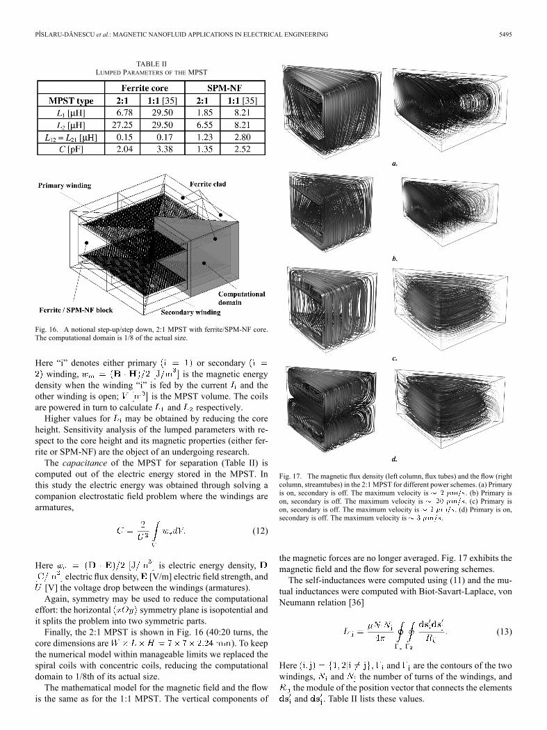
core dimensions are ). To keepthe numerical model within manageable limits we replaced thespiral coils with concentric coils, reducing the computationaldomain to 1/8th of its actual size.The mathematical model for the magnetic field and the flow
is the same as for the 1:1 MPST. The vertical components of
Fig. 17. The magnetic flux density (left column, flux tubes) and the flow (rightcolumn, streamtubes) in the 2:1 MPST for different power schemes. (a) Primaryis on, secondary is off. The maximum velocity is . (b) Primary ison, secondary is off. The maximum velocity is . (c) Primary ison, secondary is off. The maximum velocity is . (d) Primary is on,secondary is off. The maximum velocity is .
the magnetic forces are no longer averaged. Fig. 17 exhibits themagnetic field and the flow for several powering schemes.The self-inductances were computed using (11) and the mu-
tual inductances were computed with Biot-Savart-Laplace, vonNeumann relation [36]
(13)
Here , and are the contours of the twowindings, and the number of turns of the windings, andthe module of the position vector that connects the elementsand . Table II lists these values.
5496 IEEE TRANSACTIONS ON MAGNETICS, VOL. 49, NO. 11, NOVEMBER 2013
IV. CONCLUSIONS
A ferrofluid with colloidal nanoparticles of wassynthesized by the co-precipitation method in the molar ratio
using oleic acid like surfactant, anddispersed in transformer oil of UTR 40 type. The averagecrystallites size is 14 nm, as determined by X-ray diffraction,and in the range 10–30 nm, by scanning electron microscopy.Elemental analysis shows that the resulting powder con-
tains 70.14% Fe, 24.96% O, 4.16% C, and 0.74% Cl (theresidues). The presence of is exhibited by elementalFe peaks about 6.45 keV and 0.75 keV. The curve of firstmagnetization pinpoints an important physical property ofmagnetic fluids, namely the value of the saturation magnetiza-tion . This gives the concentration of magneticnanoparticles , which is low.For normal shear stresses (less than ) stable magnetic
fluids have a Newtonian behavior. The investigation methods ofmicrostructural and flow properties, by vibrating samplemagne-tometry (VSM) and rheometry, indicate a high colloidal stabilityfor themagnetic fluid sample based onUTR 40, with par-ticles and oleic acid as monolayer surfactant, and the existenceof a small fraction of agglomerates.The properties (magnetic, electric, heat transfer) of magnetic
nanofluid may be tailored to meet specific requirements. Thepaper presents three applications of the magnetic fluid: an elec-trical power transformer, amicroactuator, and aminiature planarspiral transformer. Numerical simulation is used in their designphase to evaluate the electromagnetic field, the heat transfermechanisms, and the electrical circuit, lumped parameters.The numerical simulation results reveal that a vertical config-
uration for the electrical transformer provides for better usage ofthe cooling ferrofluid, where the magnetization body forces addto the thermal, gravitational forces in conveying the heat to theambient. In the vertical design these forces add to the thermalflow, and the overall effect is the enhancement of the heat trans-ferred from the aggregate active parts (core, windings) to theambient.The use of the magnetic nanofluid coolant implies structural
changes made to the active parts (windings and magnetic core),as well as to the cooling tank, and creates the conditions forimproving the heat transfer with consequences in increasing thesafety operation of the unit. The construction of the power trans-former are less demanding in active materials, copper, siliceoussheet of metal and cooling agent, as compared to the standard(transformer oil) electrical transformer. Hence, following the in-tensification of the cooling effect due to the presence of the mag-netic nanofluid, the weight and dimensions of the transformerwith magnetic fluid are smaller as compared to the standardtransformers at the same rated voltage and power.The PWM controlled microactuator with SPM-NF provides
for a fast reaction to the magnetic field that is produced by elec-trical currents triggered by train pulses. The associatedmagneticfield generates magnetic forces that are significant in the regionsof higher field non-uniformity. These forces entrain the fluid ina wavy motion observable mainly above each powered coil forfrequencies, , between 1 and 25 Hz and duty cycles, , inthe range 50%–90%.A notional 1:1 micro-planar-spiral-transformer (MPST) fab-
ricated in MEMS technology for galvanic separation, proposedto equip an EHD device with magnetic nanofluid core adds to
the applications of the magnetic nanofluid. Its lumped param-eters are comparable is its counterpart MPST with ferrite core.Magnetization body forces occur in the fluid core, resulting in astationary flow.The flow pattern is complex and it depends on the structure of
the magnetic field, hence the powering scheme of the windings.For the 1:1MPST, a larger, fully 3D, four lobbed trefoil cell, thatentrains four external, and four smaller, inner, recirculation cellswere noticed. For the 2:1 MPST replacing the spiral windingswith concentric coils results in symmetry in the flow pattern,which is now composed of eight 3D recirculation cells. In bothcases, the flow pattern sensitive to the powering scheme of thewindings, more pregnant the windings are modeled as spirals.During the revision process of the manuscript it was brought
to our attention the interesting numerical and intensive experi-mental work reported in [37]. The results suggest that magneticnanofluids offer a better solution to heat transfer, e.g. an ap-proximate 6 degrees lower experimental temperature is reportedwhenmagnetic nanofluid is used in lieu of oil. This result is con-sistent with our experimental and numerical simulation findings(Section III-A).
ACKNOWLEDGMENT
The Romanian National Authority for Scientific Researchprovided partial support for this work through the project21-043/2007. The superparamagnetic nanofluid was engi-neered at ICPE-CA. Mathematical modeling and numericalsimulations were conducted in the Laboratory for MultiphysicsModeling at UPB.
REFERENCES
[1] V. Ervithayasuporn and Y. Kawakawi, “Synthesis and characterizationof core-shell type nanoparticles in poly (organosilsesquixane),”J. Colloid Interface Sci., vol. 332, pp. 389–393, 2009.
[2] L. Vekas, D. Bica, and O. Marinica, “Magnetic nanofluid stabilizedwith various chain length surfactants,” Rom. Rep. Phys., vol. 58, no. 3,pp. 257–267, 2006.
[3] K. Hayashi, W. Sakamoto, and T. Yogo, “Magnetic and rheologicalproperties of monodisperse nanoparticles/organic hybrid,” J.Magn. Magn. Mater., vol. 321, pp. 450–457, 2009.
[4] P. Paddar, T. Fried, G. Markovich, A. Sharoni, D. Katz, T. Wizansky,and O. Mills, “Manifestation of the Verwey transition in the tunnelingspectra of magnetite nanocrystals,” Europhys. Lett., vol. 64, no. 1, pp.98–103, 2003.
[5] K. Jordan, A. Cazacu, G. Manai, S. F. Ceballos, S. Murphy, and I.V. Shvets, “Scanning tunneling spectroscopy study of the electronicstructure of surfaces,” Phy. Rev., vol. 74, p. 085416, 2006.
[6] A. K. Gupta and M. Gupta, “Synthesis and surface engineering of ironoxide nanoparticles,” Biomaterials, vol. 26, pp. 3995–4021, 2005.
[7] T. Ozkaya, M. S. Toprak, A. Baykal, H. Kavas, Y. Koseoglu, and B.Aktas, “Synthesis of nanoparticles at 100 and its magneticcharacterization,” J. Alloys Comp., vol. 472, pp. 18–23, 2009.
[8] M. Chastellain, A. Petri, and H. Hofmann, “Particles size investigationsof a multistep synthesis of PVA coated superparamagnetic nanoparti-cles,” J. Colloid Interface Sci., vol. 278, pp. 353–360, 2004.
[9] R. F. C. Marques, C. Garcia, P. Lecante, S. J. L. Ribeiro, L. Noe, N. J.O. Silva, V. S. Amaral, A. Millan, and M. Verelst, “Electro-precipita-tion of nanoparticles in ethanol,” J. Magn. Magn. Mater., vol.320, pp. 2311–2315, 2008.
[10] R. A. Mukh-Qasem and A. Gedanken, “Sonochemical synthesis ofstable hydrosol of nanoparticles,” J. Colloid Interface Sci., vol.284, pp. 489–494, 2005.
[11] Y. Cai, Y. Shen, A. Xie, S. Li, and X. Wang, “Green synthesis of soyabean sprouts—Mediated superparamagnetic nanoparticles,” J.Magn. Magn. Mater., vol. 322, pp. 2938–2943, 2010.
[12] L. Cabrera, S. Gutierrez, N. Menendez, M. P. Morales, and P. Herrasti,“Magnetite nanoparticles: Electrochemical synthesis and characteriza-tion,” Electrochimica Acta, vol. 53, pp. 3436–3441, 2008.
PÎSLARU-DĂNESCU et al.: MAGNETIC NANOFLUID APPLICATIONS IN ELECTRICAL ENGINEERING 5497
[13] T. Neuberger, B. Schöpf, H. Hofmann, M. Hofmann, and B. vonRechenberg, “Superparamagnetic nanoparticles for biomedical appli-cations: Possibilities and limitations of a new drug delivery system,”J. Magn. Magn. Mater., vol. 293, pp. 483–496, 2005.
[14] D. Maity and D. C. Agrawal, “Synthesis of iron oxide nanoparticlesunder oxidizing environment and their stabilization in aqueous andnon-aqueous media,” J. Magn. Magn. Mater., vol. 308, pp. 46–55,2007.
[15] S. P. Gubin, Magnetic Nanoparticles. Weinheim:Wiley-VCHVerlagGmbH&Co., 2009.
[16] G. S. Park and S. H. Park, “Design of magnetic fluid linear pump,”IEEE Trans. Magn., vol. 35, no. 5, pp. 4058–4060, 1999.
[17] G. S. Park andK. Seo, “New design of themagnetic fluid linear pump toreduce the discontinuities of the pumping forces,” IEEE Trans. Magn.,vol. 40, no. 2, pp. 916–919, 2004.
[18] A. Nethe, T. Scholz, H.-D. Stahlmann, and M. Filtz, “Ferrofluids inelectric motors—A numerical process model,” IEEE Trans. Magn.,vol. 38, no. 2, pp. 1177–1180, 2002.
[19] I. H. Choi, S. P. Hong, W. E. Chung, Y. J. Kim, M. H. Lee, and J.Y. Kim, “Concentrated anisotropic magnetization for high sensitivityof optical pickup actuator,” IEEE Trans. Magn., vol. 35, no. 3, pp.1861–1864, 1999.
[20] J. J. Ahn, J. G. Oh, and B. Choi, “A study of the novel type of ferrofluidmagnetic pipette,” Nanotech vol. 1, 2003 [Online]. Available: www.nsti.org
[21] L. Pîslaru-Dănescu, A. M. Morega, G. Telipan, and V. Stoica,“Nanoparticles of ferrofluid synthetised by coprecipita-tion method used in microactuation process,” Optoelectron. Adv.Mater.—Rapid Commun., vol. 4, no. 8, pp. 1182–1186, 2010.
[22] J. Lis and P. O. Kellard, “Measurements of the thermal conductivity ofthin films of magnetite,” J. Phys. D: Appl. Phys., vol. 1, pp. 1117–1123,1968.
[23] L. Pîslaru-Dănescu, A. M.Morega, F. Nouras, and V. Stoica, “Thermaleffects on functional characteristics of the electrical transformers,” inELECTROMOTION 2009-EPE Chapter Electric Drives, Joint Sym-posium, 1–3 July 2009, Lille, France, CD—PROCEEDINGS Section:DS1, Paper 9: Design and Analysis of Electromagnetic Devices.
[24] A. Bejan, Convection Heat Transfer, 3rd ed. New York: Wiley, 2004.[25] , B. Berkovski and V. Bashtovoy, Eds., Magnetic Fluids and Applica-
tions, Handbook. New York: Begell House, 1996.[26] A. M. Morega, M. Morega, L. Pîslaru-Dănescu, V. Stoica, F. Nouraş,
and F. D. Stoian, “A novel, ferrofluid-cooled transformer. Electro-magnetic field and heat transfer by numerical simulation,” in 12th Int.Conf. Optimization of Electrical and Electronic Equipment, OPTIM,Brasov, Romania, May 20–22, 2010, pp. 140–146, 1842-0133, Con-ference Publications.
[28] A. M. Morega, M. Morega, F. D. Stoian, and S. Holotescu, “Numericalsimulation of an experimental apparatus for the evaluation of physicalproperties of magnetic fluids,” in COMSOL Conf., Budapest, Hungary,Nov. 24–25, 2008.
[29] A. M. Morega, L. Pîslaru-Dănescu, andM.Morega, “A novel microac-tuator device based on magnetic nanofluid,” in OPTIM 2012, 13th Int.Conf. Optimization of Electrical and Electronic Equipment, Braşov,Romania, May 24–26, 2012, pp. 1100–1106, 1842-0133.
[30] D. Lee, “Energy harvesting chip and the chip based power supply de-velopment for a wireless sensor,” Sensors, vol. 8, pp. 7690–7714, 2008.
[31] M. Bakkali, R. Carmona-Galan, and A. Rodriguez-Vazquez, A Proto-type Node for Wireless Vision Sensor Network Applications Develop-ment 9781424459964, 10.1109/ISVC2010.5656420.
[32] , O. Brand and G. K. Fedder, Eds., Advanced Micro & Nanosystems.New York: Wiley-VCH Verlag, GmBH & Co. KGaA, 2005, vol. 2,3-257-31080-0, CMOS-MEMS.
[33] J. Hogerheiden, M. Ciminera, and G. Jue, “Improved planar spiraltransformer theory applied to a miniature lumped element quadra-ture hybrid,” IEEE Trans. Microw. Theory Tech., vol. 45, no. 4, pp.543–545, 1997.
[34] T. H. Tsai, L. S. Kuo, P. H. Chen, D. S. Lee, and C. T. Yang, “Applica-tions of ferro-nanofluid on a micro-transformer,” Sensors, vol. 10, pp.8161–8172, 2010.
[35] A. M. Morega, M. Morega, J. B. Dumitru, L. Pîslaru-Dănescu, andV. Stoica, “Magnetic and electric sizing of a miniature planar spiraltransformer,” in 7th Int. Conf. Electrical and Power Engineering, EPE2012, Iaşi, Romania, Oct. 25–27, 2012.
[36] C. I. Mocanu, The Electromagnetic Field Theory. Bucharest, Ro-mania: Ed.D.P. Publishing House, 1980.
[37] G. Y. Jeong, S. P. Jang, H.-Y. Lee, J.-C. Lee, S. Choi, and S.-H. Lee,“Magnetic-thermal-fluidic analysis for cooling performance of mag-netic nanofluids comparing with transformer oil and air by using fullycoupled finite element method,” IEEE Trans. Magn., vol. 49, no. 5, pp.1856–1868, 2013.
Lucian Pîslaru-Dănescu was born in Timişoara, Romania, on March 14th,1960. He graduated at 1985 and he received Dr. degree in electrical engineeringfrom the University POLITEHNICA of Bucharest, Romania, in 2005.His employment experience included the National Research Electrical En-
gineering Institute, Department of Electrical Micromachines and Departmentof Energy Conversion and Consumption Efficiency, Research. His research in-cludes: models and prototypes development for electromagnetic, piezoelectricand magnetostrictive actuators, electromagnetic field computation, electronicsources for actuators, cryo-electrotechnics, quench protection, and sensorssignal conditioning.
Alexandru M. Morega (M’90–SM’07) was born in Bucharest, Romania, in1955. He received the Diploma (1980) and Doctoral (1987) degrees in electricalengineering from the University POLITEHNICA of Bucharest, and the Ph.D.degree in mechanical engineering (1993) from Duke University of Durham,North Carolina, USA.In 1983, he joined the Faculty of Electrical Engineering, University
POLITEHNICA of Bucharest, as an Assistant Professor, and in 1998 hebecame Professor. His current research interests include electromagnetism,heat and mass transfer, field-substance interactions, energy conversion andsources, and multiphysics modeling. He is Member of the American Society ofMechanical Engineers (ASME, M’90).
Gabriela Telipan was born in Bucharest on Nov. 19, 1957. She is graduatedfrom the University POLITEHNICA of Bucharest, Romania in 1982. She is aPh.D. student at the University of Bucharest.Her employment experience included the National Research Electrical En-
gineering Institute, Department of Micro- and Nano-electrotechnology. The re-search preoccupation includes: structural and morphological characterizationof the magnetic materials and methods of synthesis for magnetic ferrofluid.She works also in the combustible and toxic gases sensors and relative hu-midity sensors fieldmade by thick and thin technology and the synthesis of oxidesemiconductors.
Mihaela Morega (M’96) is professor of electrical engineering, with teachingand research responsibilities in applied electromagnetism, at UniversityPOLITEHNICA of Bucharest, Romania, the Faculty of Electrical Engi-neering. She received the Dipl. Eng. (1980) and Doctoral (1988) degrees inElectrical Engineering, from the same university. Her research interests andspecializations include the study of specific processes in the electro-thermaland electro-mechanical energy conversion, computer aided modeling ofelectrophysiological phenomena, characterization of the electromagnetic envi-ronment, interactions of electromagnetic field with the living matter, numericaldosimetry.
Jean Bogdan Dumitru (M’11) was born in Bucharest, on November 21, 1986.He received the Diploma (2009) and Master (2011) degrees in electrical engi-neering from the Faculty of Electrical Engineering, University Politehnica ofBucharest. Since 2011 he has been a Ph.D. student at the Doctoral School ofElectrical Engineering, University Politehnica of Bucharest. His research in-terest include multiphysics modeling, electromagnetics, heat transfer, fluid dy-namics, thermoelectrics, field-substance interaction, MEMS devices, data ac-quisition in LabView, power electronics and electric drives.
Virgil Marinescu was born in Bucharest in 1978. He received the B.E. (2003)andM.S. (2005) degrees in technological physics from University of Bucharest,Faculty of Physics Romania.Since 2005 he has been with INCDIE ICPE-CA. His research is in the field
of metallic, ceramic and carbonaceous materials used in electrical engineeringemploying a large area of characterization techniques: Field Emission ScanningElectron Microscopy coupled with Energy Dispersive microprobe (OxfordInstruments INCA Energy 250), and Focused Ion Beam on Crossbeam Auriga(Carl Zeiss), Optical Microscopy (Carl Zeiss NU-2), Mass Spectrometry(ELAN DRC-e by Perkin Elmer), Simultaneous Thermal Analysis Thermo-gravimetry and Differential Scanning Calorimetry (STA 449 Jupiter, Netzsch),also some expertise on Transmission Electron Microscopy (Lybra 200 FEby Carl Zeiss) plus sample preparation line composed by: ultrasonic disccutter, dimpling grinder, twin preparation grinder, Ion Mill and Plasma Cleaner(Fischione).