MAN B&W Diesel A/S, Copenhagen, Denmark Contents: Contents: Contents: Contents: Contents: Contents: Contents: Contents: Contents: Contents: Soot Deposits and Fires in Exhaust Gas Boiler Page Introduction ........................................................................... 3 – Rise in soot fire incidents ...................................................... 3 – Warning triangle – risk of soot fire ......................................... 4 – Scope of this paper .............................................................. 4 Chapter I Basic Information and Boiler Definitions ............................. 5 – Heat balance of a main engine .............................................. 5 – Permissible exhaust gas back-pressure ................................ 5 – Boiler types .......................................................................... 6 – Boiler steam systems ........................................................... 7 – The influence of a boiler’s pinch point .................................... 8 – Sulphuric acid corrosion ....................................................... 10 – Steam production – Influence of ambient temperatures ......... 11 – Particulate emissions from diesel engines ............................. 11 – Soot fires in exhaust gas boilers ........................................... 13 Chapter II Boiler Experience and Design Criteria ................................. 14 – Statistical analyses of soot fires ............................................ 14 – The impact of low gas velocities ............................................ 17 – Summary of main reasons for soot fires ................................ 17 – Recommended boiler design criteria ..................................... 18 – Recommended operating conditions .................................... 19 Closing Remarks ................................................................... 21 References ............................................................................. 21 This document, and more, is available for download at Martin's Marine Engineering Page - www.dieselduck.net
This document, and more, is available for download at Martin's Marine Engineering Page - www.dieselduck.net
This document, and more, is available for download at Martin's Marine Engineering Page - www.dieselduck.net
3
Soot Deposits and Fires in Exhaust Gas Boiler
Introduction
The demand for the highest possibleoverall fuel efficiency is reflected in de-velopments over the last two to threedecades in the propulsion market foroceangoing ships. Today, this market isdominated by highly efficient two-strokelow speed diesel engines which run onlow quality fuels and utilise (recover) theexhaust gas heat by means of an exhaustgas boiler/economiser.
In the same period, reduced specificfuel oil consumption, i.e. increasedthermal efficiency of the diesel engine,has resulted in lower exhaust gas tem-peratures. Based on ISO ambient refer-
ence conditions (25°C air and 25°Ccooling water), and with the presentnominal ratings of the MC/MC-C andME/ME-C engines, the exhaust gastemperature after the turbocharger isabout 240-270°C, but may be lower forderated engines.
The name “exhaust gas economiser” isoften used for an exhaust gas boiler whichis not able to operate separately, i.e.without its own steam drum. In thispaper, the name “exhaust gas boiler”will be used in general, also in caseswhere “exhaust gas economiser”, inprinciple, should have been used.
Rise in soot fire incidents
As a consequence of the lower exhaustgas temperatures and the remainingsteam consumption requirements, theexhaust gas boiler has been designedto become more and more efficient.This involves the use of a large heattransfer surface and thus a boiler designwith a low internal gas velocity as wellas tubes with “extended” surfaces.
Furthermore, the quality of the fuels hasdecreased significantly during the sameperiod. Whereas the average fuel qual-ity may not have deteriorated as much
Fig. 1: Number of soot-fire-damaged exhaust gas boilers in DnV- classed vessels
1982 84 86 88 90 92 94 96 98 00 2002 2004
70
60
50
40
30
20
10
0
Number of soot fire/overheating incidents per year
Year
This document, and more, is available for download at Martin's Marine Engineering Page - www.dieselduck.net
4
as predicted, single deliveries haveshown exceedings of the normal data,as a result of a more efficient refineryprocess. The residual fuel oils availableon the market today contain consider-ably higher quantities of asphalt, carbonand sulphur that contaminate the ex-haust gas and thereby increase the riskof soot deposits on the exhaust gasboiler tubes.
In recent years, and possibly as a con-sequence of both the deteriorated fueland the above highly efficient and perhaps“overstretched” design, it also seemsthat the tendency to fouling, i.e. sootdeposits on the exhaust gas boiler tubes,has increased and, in some cases, hasresulted in soot fires. In extreme cases,the soot fire has developed into a hightemperature iron fire in which the boileritself burns. The above-mentioned ten-dency is confirmed by DnV’s statistics,which reveal a sudden rise in soot fireincidents since 1985, see Fig. 1 andRef. [1], a rise, which may also havebeen caused by slow steaming of shipsdue to the low freight rates in recentyears.
Since 1998, we have again seen a fallin the number of incidents, probablycaused by the effect of the new recom-mended exhaust gas boiler design crite-ria introduced about 10 years ago, anddescribed in this paper.
It is evident that the high fuel efficiencytarget must be met without jeopardisingthe reliability of the ship. It is thereforeimportant to know the main reasons forthe occurrence of soot deposits andfires so we can take the proper coun-termeasures against them with a correctexhaust gas boiler/system design, etc.
Warning triangle –risk of soot fire
When soot fires occur, the diesel enginewill normally be blamed since the sootparticles in fact originate from the engine’sfuel combustion. As, in principle, particlesin the exhaust gases are unavoidablefrom a modern diesel engine running onheavy fuel Ref. [1], the causes of soot de-posits/fires may be approached by ask-ing a different question: What makes thesoot particles deposit and/or whatcauses the ignition of the soot deposits?
This question may be illustrated by the“warning triangle” in Fig. 2 showing thethree factors which are all needed for asoot fire: soot deposits, oxygen and igni-tion. As the exhaust gas smoke from adiesel engine, due to its high air excessratio, contains about 14% oxygen, thesoot deposits and ignition items are ofparticular interest, as the oxygen can-not be removed.
Scope of this paper
This paper is divided into two chapterswhich, in principle, may be consideredas two separate papers.
The intention with Chapter I is to give aquick introduction to the most com-monly-used exhaust gas boiler types,steam systems and relevant param-eters. Reading this chapter will form agood introduction before proceeding tothe issues of principle discussed inChapter II.
Chapter II deals with the essential con-ditions causing soot deposits and firesin exhaust gas boilers. The reasons forsoot deposits and their ignition are iden-tified on the basis of statistical materialetc. In this context, recommendationsare given which are relevant to the de-sign and operation of exhaust gas sys-tems and boilers.
Fig. 2: Warning triangle - risk of soot fire
Igni
tion
(of t
heso
ot) O
xygenO
(inexhaust gas
smoke)
2
Soot deposits(on boiler tubes)
This document, and more, is available for download at Martin's Marine Engineering Page - www.dieselduck.net
5
Basic Information andBoiler Definitions
Heat balance of a main engine
When considering a heat balance diagramwhich, by way of example, is shown inFig. 3 for a nominally rated highly efficientengine version 6S60MC-C (or 6S60ME-C),operating on 80% SMCR (80% of speci-fied maximum continuous rating), the mostattractive waste heat source is the exhaustgas heat. Approximately one fourth ofthe fuel energy comes out as exhaustgas heat.
Even though the exhaust gas temperaturethe last 25 years has decreased about130°C, from approx. 375°C to approx.245°C (ISO), as a result of the obtainedhigher efficiency of diesel engines, exhaustgas boilers are installed on almost allmerchant ships of today. However, thisdevelopment has been accompaniedby more trouble, as mentioned before.
Chapter I
Permissible exhaust gasback-pressure
The permissible gas pressure loss acrossthe exhaust gas boiler has an importantinfluence on the gas velocity through theboiler. Thus, if a high pressure loss isacceptable, it is possible to design theboiler with a high gas velocity, but if onlya small pressure loss is permissible, thegas velocity will be low.
The permissible pressure loss across theboiler depends on the pressure lossesof the total exhaust gas system after thediesel engine’s turbocharger(s).
Permissible back-pressure of exhaustgas system for MC/MC-C andME/ME-C engines
At the specified MCR of the engine, thetotal back-pressure in the exhaust gassystem after the turbocharger, indi-cated by the static pressure measuredas the wall pressure in the circular pipeafter the turbocharger, must not exceed350 mm WC (0.035 bar), see Fig. 4.
In order to have a back-pressure marginfor the final system, it is recommendedat the design stage that about 300 mmWC (0.030 bar) at specified MCR isused initially.
The back-pressure in the exhaust gassystem depends on the gas velocity,i.e. it is proportional to the square of theexhaust gas velocity, and hence to the pipe
Fig. 3: Heat balance of main engine at 80% SMCR Fig. 4: Permissible exhaust gas back-pressure at 100% SMCR
6S60MC�C
Lubricatingoil cooler
3.3%
Exhaust gas25.0%
Air cooler14.6%
Jacket watercooler5.8%
Heat radiation0.8%
SMCR: 13,560 kW and 105.0 r/minService point: 80% SMCR
Shaft poweroutput 50.5%
Fuel100%
Sparkarrester
Exhaustgassilencer
Exhaustgasboiler
T/C
∆Max p 350 mm W.C.system <
∆
∆
∆
∆
∆Design p 300 mm W.C.system <
p1
p2
p3
psystem
This document, and more, is available for download at Martin's Marine Engineering Page - www.dieselduck.net
6
diameter to the 4th power. It is recom-mended not to exceed 50 m/s in theexhaust gas pipes at specified MCR.
It has become normal practice, in orderto avoid too much pressure loss, to havean exhaust gas velocity in the pipes ofabout 35 m/sec at specified MCR.
As long as the total back-pressure ofthe exhaust gas system, incorporatingall resistance losses from pipes andcomponents, complies with the above-mentioned requirements, the pressurelosses across each component, suchas the exhaust gas boiler and silencer,may be chosen independently.
Permissible pressure loss across boiler
At specified MCR, the maximum recom-mended pressure loss across the exhaustgas boiler is normally 150 mm WC.
This pressure loss depends on the pres-sure loss in the rest of the system, asmentioned above. Therefore, if an ex-haust gas silencer/spark arrester is notinstalled, the acceptable pressure lossacross the boiler may be somewhathigher than the maximum of 150 mmWC, whereas, if an exhaust gas si-lencer/spark arrester is installed, it maybe necessary to reduce the maximumpressure loss.
It should be noted that the above-men-tioned pressure loss across the boiler alsoincorporates the pressure losses from theinlet and outlet transition boxes.
Boiler types
The types of exhaust gas boilers utilisingthe diesel engine exhaust gas heat may,in principle, be divided into two maingroups:
• Water tube boilers
• Smoke tube boilers
Water tube boilers
This is the boiler type most frequentlyused – often in connection with highexhaust gas heat utilisation. The exhaustgas is passed across the outside of theboiler tubes, with the water flowing inside,see Fig. 5. In order to make the boileras efficient and as compact as pos-sible, the heat transfer area on the gasside of the tubes may often be ex-panded with, for example, narrowlyspaced, gilled (finned) or pinned tubes.
The clearance between the gill-type fins(face to face) is in general 10-13 mm,and the thickness of the gills is about2-3 mm.
The water tube boiler type will normallynot be equipped with a steam space(also called steam collector or steamdrum), but will sometimes be operatedin connection with a separate steamdrum or, more often, with the steamdrum of the oil-fired boiler.
Fig. 5: Exhaust gas boiler – water tube type The boiler shown is the vertical type without steam drum
Fig. 6: Exhaust gas boiler – smoke tube type The boiler shown is the vertical type
with steam drum
Gilled tubes Pinned tubes
Plain tubes Spiral tubes
Exhaust gas
Water tubes
Different types of water tube elements:
Steam drum(Space)
Water
Smoketubes
Exhaust gas
This document, and more, is available for download at Martin's Marine Engineering Page - www.dieselduck.net
7
Fig. 7: Normal exhaust gas boiler system for steam production Single pressure steam system with evaporator section only
The soot deposits on the upper side ofthe boiler tubes, and this type of boilerwill most often be fitted with a soot-blowingarrangement in order to remove any sootdeposits. The soot depositing tendencyhas been on the increase due to the lowgas velocity and temperature often used.
In several cases, the increased occur-rence of soot deposits on this type ofboiler has been followed by a soot fire.
In extreme cases – as mentioned later –the high temperature caused by the sootfire has resulted in a so-called iron fire inwhich the boiler itself burns. This may haveoccurred due to leakage of water from theboiler because of the high temperature.The iron fire could also have occurred be-cause the crew tried to put out the fire byactivating the soot blowers for the injec-tion of steam or water. The high tem-perature would thus cause dissociationof steam into oxygen and hydrogen. Theoxygen may then have caused oxidationof the iron, i.e. an iron fire.
Gilled and pinned tubes are more vulner-able to soot fires than plain tubes, be-cause the highest metal temperatureswill occur on the edge of the gills, whichwill thus be the most likely starting pointfor an iron fire.
Smoke tube boilers
In the smoke tube boilers, the gas isconducted through a bundle of tubes withsmall internal diameters (of the magnitudeof 30-100 mm) and surrounded on theoutside by water, see Fig. 6. The smoketube boiler type is often chosen in speci-fic cases where it is desirable to operatethe exhaust gas boiler independently ofthe oil-fired boiler. This is possible as thesmoke tube boiler may be fitted with itsown separate steam drum.
In general, a high gas velocity in the boilertubes is desirable, in order to achieve thehighest possible heat transfer and thelowest possible soot deposits.
As a cleaning system is very difficult toinstall, this boiler type is designed to havea self-cleaning effect, which is obtainedby using a relatively high design mean gasvelocity, exceeding some 20 m/s, throughthe tubes.
In some cases soot has blocked someof the boiler tubes, with a consequentincrease in pressure loss and reductionin boiler efficiency. The solution may beto clean the tubes manually at regularintervals, although this may be expensive.
On the other hand, the soot depositshave very seldom led to damage causedby soot fire, because the boiler tubes aresurrounded/cooled by water and the heatsurface has a limited area.
Boiler steam systems
Exhaust gas boiler steam systems canbe designed in many different versions,with one or two pressure levels, with orwithout preheater section, etc.
As examples, the most commonly usedsteam systems – both simple and ad-vanced – are described below.
Normal exhaust gas boiler system
The exhaust gas boiler system normallyused for the production of saturatedsteam needed for heating services isshown in Fig. 7.
This is a simple, single-pressure steamsystem in which the exhaust gas boilerconsists solely of an evaporator section.The feed water is pumped directly tothe oil-fired boiler which is used as a
Exhaustgas boilerevaporator
Saturatedsteam forheating services
Exhaust gas Oil�firedboiler withsteam drum
Feedwaterpumps
Circulatingpumps
Hot well
Atmos�phericsurpluscondenser
This document, and more, is available for download at Martin's Marine Engineering Page - www.dieselduck.net
8
Exhaust gas boilerPreheater
Evaporator
Superheater
Feedwaterpump
Atmos�phericsurpluscondenser
Oil�firedboiler withsteam drum
Exhaust gas
Saturatedsteam forheatingservices
Hot well
Turbogenerator(steam turbine)
Condenser
Condensate pumps
Heatexc.
Steam/water 7 bar abs
Exhaust gasSuperheatedsteam
Saturatedsteam
Superheater Evaporator Preheater
Exhaust gas
Pinchpoint
Heat trans�mission Q
0% 20% 40% 60% 80% 100%
300
250
200
150
100
50
0
OC Temperature T
Feedwater
Fig. 9: T/Q diagram for an exhaust gas boilerFig. 8: Special exhaust gas boiler system with turbo generator forelectricity productionSingle pressure steam system with preheater, evaporatorand superheater sections
common steam drum for the oil-firedboiler and the exhaust gas boiler.
Separate steam drums may also beused, so that one boiler can be run ifthe other should malfunction.
Because of its simplicity and low capitalcost, the above system is widely usedand is often entirely adequate when thesteam production is viewed as a meansof meeting the steam demand for heat-ing services on the ship.
The loss of water from the exhaust gasboiler is in the magnitude of about 1%of the steam production.
Special exhaust gas boiler systemwith turbogenerator
When a turbogenerator, i.e. a steamturbine driven electrical generator, is in-
stalled (utilising the steam available afterdeduction of steam for heating ser-vices), the exhaust gas boiler systemwill be more advanced.
An example of such a system is shownin Fig. 8. The boiler is, apart from theevaporator, also fitted with a preheaterand superheater. In this system too,the steam drum of the oil-fired boiler isnormally used as a common steam drum.
The influence of a boiler’spinch point
A boiler’s pinch point is a parameter thatcan tell us a lot about the boiler’s designand potential behaviour in operation. Itwill therefore be defined below, and itsinfluence on some important boiler para-meters will be discussed in this section.
A boiler’s T/Q diagram and definitionof pinch point
A temperature/heat transfer diagram, aso-called T/Q diagram, illustrates thecharacteristic temperature coursethrough the exhaust gas boiler. As anexample valid for the special exhaustgas boiler system shown in Fig. 8, a T/Qdiagram is shown in Fig. 9.
The utilisation efficiency of an exhaustgas boiler is characterised by its pinchpoint. The pinch point is the lowesttemperature difference between the ex-haust gas and the saturated steam, i.e.the temperature difference between theexhaust gas leaving the evaporatorsection and the saturated steam, seethe T/Q diagram in Fig. 9.
Normally, the steam pressure will be above7 bar abs. (6 barg) and often equal to 8
This document, and more, is available for download at Martin's Marine Engineering Page - www.dieselduck.net
9
Fig. 10: Influence of a boiler´s pinch point, relative to 15 oC. The graph shows the relative influence of the pinchpoint on an exhaust gas boiler´s heat transfer surface (size and investment) and steam production [3]
bar abs. (7 barg), corresponding to aminimum evaporation temperature of165°C. According to the T/Q diagramthe gas outlet temperature, even for aboiler with feed water preheater section,will therefore not be lower than about165°C, when 20°C or above is used asthe pinch point.
A boiler’s steam production andheat transfer surface
The influence of the pinch point on theexhaust gas boiler design will be evidentfrom the following example.
The graphs in Fig. 10 show the influenceof the pinch point on the boiler’s heattransfer surface and steam production [3].
By way of example, the graphs in Fig.10 indicate that an exhaust gas boilerwith a pinch point of 5°C, comparedwith one with a pinch point of 15°C, willproduce 10% more steam, but at theexpense of having a heat transfer sur-face about 2.3 times that of the originalboiler surface, and the gas velocitythrough the boiler may be correspond-ingly reduced, as otherwise the pressureloss across the boiler might be too high.
A boiler’s pressure loss and gasvelocity
In principle, the pinch point may beconsidered a measure of how extensiveand how efficient the heat utilisation ofthe exhaust gas boiler is.
The lower the pinch point, the larger theheat transfer surfaces and the more ef-ficient is the exhaust gas boiler, and thehigher is the gas pressure loss acrossthe boiler. As the maximum permissiblegas pressure loss has a certain limitation,the boiler’s design gas velocity has to bereduced in order not to exceed the limitfor the permissible gas pressure loss.
This is what has happened with themore efficient exhaust gas boiler designduring the past two decades becauseof the lower exhaust gas temperaturesof the diesel engines. In this context,Chapter II will show that a low gas velo-city in particular will have a distinct influ-ence on the tendency towards soot de-posits, a tendency which has become
80 60 50 40 30 20 15 10 5 3 Pinch point Co
%125
110105100
75
50
25
232225
200
175
150141
125
100
75
50
25
0
Temperature
C
230
220
210
200
190
180
170
160
o
Steam
production
Outlet gas temperature
Relative heattransfer surface
Heat
trans
fer s
urfa
ceExample:132% larger exhaust gas boilerrequired to produce 10% moresteam at 5 C pinch pointcompared with 15 C
o
o
Steam temperature
Relativesteamproduction
This document, and more, is available for download at Martin's Marine Engineering Page - www.dieselduck.net
10
Fig. 11: Sulphuric acid dew point of exhaust gas shown as a function of the sulphur content in the fuel
Fig. 12: Influence of ambient air temperature on the exhaust gas temperature afterturbocharger for a 6S60MC-C
Sulphuric acid corrosion
A high degree of utilisation of the exhaustgas heat requires the lowes possibleexhaust gas boiler outlet temperaturewhich, if the required steam pressureand thereby the evaporation tempera-ture is sufficiently low, is limited mainlyby the risk of corrosion of the exhaustgas boiler heating surfaces due tosulphuric acid condensation.
Corrosion starts when the temperatureof the boiler tube surfaces is equal to, orlower than, the dew point temperatureof the sulphuric acid. Furthermore, thetemperature of the boiler tube surfaces(gas side) is almost equal to the watertemperature in the boiler, due to the factthat the heat transfer coefficient on thegas side is extremely low compared tothat on the water side.
The sulphuric acid dew point tempera-ture depends especially on the contentof sulphur in the fuel oil and of oxygen inthe exhaust gas, but is rather difficult toestablish. The chemical reactions areas follows:
a. at fuel combustion:
S + O2 ĄĄĄĄĄ SO2
b. at cooling of exhaust gas in the tem-
perature range of 560° - 200°C:
2SO2 + O2 ĄĄĄĄĄ 2SO3
c. at reaction with water:
SO3 + H2O ĄĄĄĄĄ H2SO4
The chemical reaction b), in particular,is rather difficult to establish, the reasonbeing that the reaction takes placerather slowly and is catalysed by sootdeposits, etc., on the heating surfaces.
Valid for the exhaust gas after turbo-charger from MC/MC-C or ME/ME-Cmain engines, Fig. 11 shows, as aguide, the sulphuric acid dew point as afunction of the sulphur content in thefuel. With an average 2.9 % sulphurcontent in the fuel, the dew point of
worse due to the low quality residual fu-els on the market today.
Low pinch point and soot deposits
The pinch point is therefore a param-eter that may influence the occurrenceof soot deposits when the pinch point
and thus the gas velocity is low. Con-versely, a boiler designed with a highpinch point need not be a boiler with ahigh gas velocity. Such a boiler can, inprinciple, also be designed with a lowgas velocity, i.e. a low gas pressureloss across the boiler.
C150
140
130
120
110
0
o
0 1 2 3 4 5 wt %
Approximated sulphuric acid dew pointC150
140
130
120
110
100
o
Sulphur (S) content in fuel
C350
300
250
200
0 Exhaust gas temperature after T/C �/+ 15 Co
30 40 50 60 70 80 90 100 110 % SMCR
Engine shaft power
Tropical (45 C air)o
ISO (25 C air)o
Winter (10 C air)o
This document, and more, is available for download at Martin's Marine Engineering Page - www.dieselduck.net
11
Fig. 13: Influence of ambient air temperarure on the steam production of an exhaust gas boiler installed on an Aframax tanker with main engine 6S60MC-C
sulphuric acid in the exhaust gas fromthe main engine can be expected to beabout 135°C, which means that in thiscase the temperature of boiler circulat-ing water or feed water at the boiler in-let should be kept higher than 135°C.
Steam production – Influenceof ambient temperatures
During normal operation of the ship, theambient air and seawater temperatureswill change, and this will have an influenceon the exhaust gas temperature.
Thus, the exhaust temperature after turbo-chargers will decrease about 1.6°C foreach 1.0°C reduction of the turbochargerintake air temperature, and vice versa.
As an example, valid for a 6S60MC-Cengine, Fig. 12 shows the influence ofthe turbocharger air intake temperatureon the exhaust gas temperature, validfor ISO reference conditions (25°C air/25°C c.w.), tropical air temperature of45°C and a winter air temperature of10°C, respectively.
The similar example (see Fig. 13) validfor an Aframax tanker having a 6S60MC-Cmain engine installed, shows the corre-sponding steam production of an exhaustgas boiler with an evaporator section only,and based on the steam pressure of 8bar abs., and 20°C pinch point, togetherwith the needed steam consumption forheating services. The upper graph for theISO (25°C air) based boiler design showsthat too much steam will be produced,
and the surplus steam has to be dumpedby means of the atmospheric surplus con-denser. However, in winter time (10°C air)with a lower exhaust gas temperature,the steam production will be lower, where-as the steam consumption will increase,meaning that the oil fired boiler may occa-sionally have to start up to supplement thesteam production.
Particulate emissions fromdiesel engines
Low speed diesels have been leadingthe way with regard to the acceptanceof low-grade fuels, low fuel consumptionand high reliability. In this process, thepresence of particulates in the exhaustgas, from an operational point of view,always has been, and no doubt alwayswill be, unavoidable.
The typical exhaust gas emission valuesfor the most commonly discussed pol-lutants, NOx, SOx, CO, HC, and parti-culates, are shown in Fig. 14. In thecontext of this paper, only the particu-late/soot emissions, and to some degreethe hydrocarbons (HC), are of interestand will be described in the following.
Sources of particulate emissions
Particulates in the exhaust gas mayoriginate from a number of sources:
• Agglomeration of very small particlesof partly burnt fuel
• Ash content of fuel oil and cylinderlube oil
• Partly burnt lube oil
• Peeling-off of combustion chamber/exhaust system deposits.
Typical form and rate of particulateemissions
Once fuel is atomised in the combus-tion chamber of a diesel engine, the
1,000
3,000
2,000
Engine shaft power
0
Steam consumption
Extra steam needed
1,000
0
2,000
Steam consumption
Surplus steam
50 60 70 80 90 10040
50 60 70 80 90 100
%SMCR
40
Total steamproduction
Winter ambient conditions (10 C)o
ISO ambient conditions (25 C)o
Steam productionkg/h Total steam
production
Steam productionkg/h
%SMCR
This document, and more, is available for download at Martin's Marine Engineering Page - www.dieselduck.net
12
Fig. 16: High temperature fire of a gas fired water tube type boilerFig. 15: Development of a soot fire in an exhaust gas boiler
Fig. 14: Typical emissions from an MC/ME type low speed diesel engine
Stage 1 Ignition of soot Type of soot Potential ignition temperature Dry soot 300-400 °C Wet (oily) 150 °C (120 °C)
Stage 2 Small soot fires Small soot fires are most likely to occur during
manoevring/low engine load with no or limitedboiler damage
Stage 3 High temperature fires A small soot fire may develop into a
high temperature fire with the following reactions involved:
a. Hydrogen fire, temperature > 1,000 °C Dissociation of water into hydrogen and oxygen:
2H2O ĄĄĄĄĄ 2H2 + O2 }H2 and CO are combustibleH2O + C ĄĄĄĄĄ H2 + CO
b. Iron fire, temperature > 1,100 °C Examples of reaction with iron:
combustion process takes place fromsmall droplets of fuel which evaporate,ignite, and are subsequently burnt.During this process, a minute part ofthe oil, comprising mainly carbon, willbe left as a “nucleus”.
Particulate emissions will vary substan-tially with the fuel oil composition andlube oil type and dosage. It is thereforedifficult to state general emission ratesfor particulates, but when the engine isoperating on heavy fuel oil, values ofthe order of 120-150 mg/Nm3, corre-sponding to some 0.8-1.0 g/kWh, maybe considered typical.
14.0% O2
76.2% N2
4.5% CO2
5.1% H2O1500 ppm NOx
600 ppm SOx
60 ppm CO 180 ppm HC 120 mg/Nm3 part
21% O2
79% N2
97% HC 3% S
97% HC 2.5% CA
0.5% S
Heat
This document, and more, is available for download at Martin's Marine Engineering Page - www.dieselduck.net
13
In general, the particles are small and,when the engine operates on heavy fueloil, it may be expected that over 90%of them will be less than 1 micron in size,excluding flakes of deposits, and peel-ing-off from the combustion chamber orexhaust system walls.
The particulates also include some ofthe ash content of the oil, i.e. the tracemetals. The above-mentioned contribu-tion from the lubricating oil consistsmainly of calcium compounds, viz.sulphates and carbonates, as calciumis the main carrier of alkalinity in lube oilto neutralise sulphuric acid.
A test of the soot deposits in a boilerwith gilled tubes has shown that about70% of the soot is combustible.
Hydrocarbons
During the combustion process, a verysmall part of the hydrocarbons will leavethe engine unburnt, and others will beformed. These are referred to as unburnthydrocarbons, and they are normallystated in terms of equivalent CH4 content.
The content of unburnt hydrocarbons inthe exhaust gas from large diesel enginescan be up to 300 ppm, but depends,among other factors, very much on themaintenance condition of the fuel injec-tion system and, to some extent, on thetype of fuel and the cylinder oil dosage.
The hydrocarbon figure to some extentoverlaps the figure for particulates, asthese consist partly of hydrocarbons.
Sticky effect of particulate emissions
If the right – or rather the wrong – con-ditions prevail, the soot particulatesmay deposit in the exhaust gas boiler.
Furthermore, the lower the exhaust gasand heating surface temperatures be-come, the faster the soot is depositedand the harder it becomes to remove it.The explanation is that under such con-
ditions the soot may be “wet” with oiland/or other gas condensates like hydro-carbons, and this may have an increas-ing effect on the tendency of soot todeposit, as the soot may be more sticky.
Soot fires in exhaust gas boilers
A fire in the exhaust gas boiler may de-velop in two or three stages, see Fig.15 and Ref. [2]. The ignition of soot nor-mally develops into a small and limitedfire, but under extreme conditions itmay develop into a high-temperature fire.
Ignition of soot
Ignition of soot may arise in the presenceof sufficient oxygen when the depositsof combustible materials have a suffi-ciently high temperature (higher thanthe flash point) at which they will liberatesufficient vapour, which may be ignitedby a spark or a flame.
The main constituent of the soot depositis particulates but, in addition, someunburnt residues of fuel and lubricatingoils may be deposited in the boiler be-cause of faulty combustion equipmentand, in particular, in connection withstarting and low speed running of theengine.
The potential ignition temperature of thesoot layer is normally in the region of300-400 oC, but the presence of unburntoil may lower the ignition temperatureto approx. 150 oC, and under extremeconditions even down to 120 oC.
This means that ignition may also takeplace after stop of the main engine asa result of glowing particles (sparks)remaining on the boiler tubes.
Small soot fires
Small soot fires in the boiler are mostlikely to occur during manoeuvring withthe main engine in low load operation.These fires do not cause damage tothe boiler, or damage is very limited, butthe fires should be carefully monitored.
Heat from the fire is mainly conductedaway with the circulation water andsteam and with the combustion gases.
High-temperature fires
Under certain conditions, a small sootfire may develop into a high-tempera-ture fire. The photo in Fig. 16 shows anexample of an exhaust gas boiler whichhas had a high-temperature fire, wherethe boiler tubes have burned and melted.The reactions involved here are (see alsostage 3 in Fig.15).
a. Hydrogen fireThis occurs because dissociation ofwater into hydrogen and oxygen or, inconnection with carbon, into carbonmonoxide and hydrogen, may occurunder certain conditions. A hydrogenfire may start if the temperature isabove 1000 oC.
b. Iron fire An iron fire means that the oxidation
of iron at high temperatures occurs ata rate sufficiently high to make theamount of heat release from the re-actions sustain the process. Thesereactions may take place at a tem-perature in excess of 1100 oC.
In this connection, it is important torealise that also water (H2O) may goin chemical reaction with iron (Fe),i.e. the use of the steam based sootblower will feed the fire.
This document, and more, is available for download at Martin's Marine Engineering Page - www.dieselduck.net
14
Boiler Experience andDesign Criteria
Statistical analyses of soot fires
Soot fires in exhaust gas boilers werevery unusual some years ago but, duringthe last two decades, soot depositsand soot fires have occurred more often.
Analyses of soot fires indicate that, inmost cases, they occur in connectionwith manoeuvring, often following astay in harbour.
On the basis of a sample of 82 ships,most of which are equipped with two-stroke main engines and water tube typeboilers, the NK “Guide to Prevention ofSoot Fire on Exhaust Gas Economizers1992”, Ref. [4], presents a statisticalparameter survey of soot fires. The sur-vey covers 53 ships with troubles (sootfire and damage) and, for comparisonpurposes, also 29 NK ships with notroubles. The engines are in the powerrange of about 4,000-30,000 kW, andabout 10% of the boilers are of thelarge capacity types, including dualpressure type boilers.
It should be noted that ships with troubleswere extracted from a representativesample of all NK ships, while ships withno troubles were limited to cases inwhich NK received answers from ship-yards or boiler makers.
The parameters stated below have(where known) been obtained from theshipyards and boiler makers in question.The parameters have been studied withregard to any distinct influence on boilertroubles and, if any such influence wasfound, it is indicated in Table 1.
Trouble/no trouble comparisons for someof the most interesting parameters havebeen made in graphical form and areshown in Figs. 17, 18, 19, 20 and 21.Even though the ships included in the
Chapter II
examination have been freely selected,for which reason simple comparisonscannot be made, the results of thecomparisons may be considered as be-ing very indicative.
Influence of main engine type
It is rather interesting, but not surprising,to see that, as shown in Fig. 17, themake and type of main engine had nodistinct influence on the risk of soot fire.
Fig. 17: Boiler trouble – influence of main engine type
Table 1: Statistical parameter survey of soot fires in exhaust gas boilers Ref.: Nippon Kaiji Kyokai, Tokyo (NK)
Parameter Any distinctParameter Any distinctParameter Any distinctParameter Any distinctParameter Any distinct influence? influence? influence? influence? influence?Ship type noMain engine type no Fig. 17Main engine(s) MCR power noBoiler sections (evaporator, preheater, etc.) noType of boiler tubes (plain, gilled, etc.) no Fig. 18Exhaust gas inlet/outlet temperatures no Fig. 19Design mean gas velocity in exhaust gas boiler yes Fig. 20Water inlet velocity to boiler yes Fig. 21Circulation water flow ratio yes Fig. 21
12
10
8
6
4
2
0K L�MC K�MC RND RTA D E H L KZ L P�4
L�G S�MC RD RL V
MAN B&W Sulzer Mitsubishi UE MAN Pielstick
Main engine types
Trouble
No trouble
Number of cases
This document, and more, is available for download at Martin's Marine Engineering Page - www.dieselduck.net
15
Thus, the ships equipped with, for ex-ample, MAN B&W, Sulzer or Mitsubishitwo-stroke main engines, all seem tohave had the same relative number ofcases with and without soot-fire troubles.Furthermore, statistics show that theoccurrence of soot fires is also largelyindependent on whether it is a short ora long stroke engine.
There is no information regarding thetype of fuel oil, but, as we are dealingwith two-stroke engines, heavy fuel oilis probably used. Operating the engineon heavy residual fuels of low qualityprobably has an increasing effect onthe tendency towards soot deposits.As low quality heavy residual fuels arecheap, this tendency may be consideredas an unavoidable parameter now andin the future (unless, for example, specialfuel additives are used, as indicated inrecent information). Special featuresregarding “Operation on Heavy ResidualFuels” have earlier been described in anMAN B&W Diesel paper, Ref. [5].
Influence of extended tube surface
Fig. 18 shows, somewhat surprisingly,that the shape of the water tube ele-ments used in exhaust gas boilers of thewater tube type had no distinct influenceon the tendency towards soot fires.
Fig. 18: Boiler trouble – influence of type of boiler tubes. One exhaust gas boiler may count more than once as preheater sections, evaporator sections, etc, are considered as separate cases
Fig. 19: Boiler trouble – influence of exhaust gas inlet and outlet temperature
In fact, the type of boiler fitted with plaintube elements had almost the samerelative number of soot fire problems asboilers fitted with tube elements with anextended surface. On the other hand, the
severe cases of soot fire, with burningdown of the tube elements themselves,may be more of a risk for boilers withextended tube surface than for thosewith plain tubes, because the potentialarea is bigger, or should we say forms areservoir for soot deposits.
Influence of exhaust gas temperature
It has often been claimed that the latestdevelopment of diesel engines, involvinglower exhaust gas temperatures, is cau-sing the soot deposits in the exhaust gasboilers.
On the other hand, when we only con-sider the influence of the exhaust gastemperature itself, the statistical analy-ses show rather clearly that this is notcorrect, see Fig. 19.
Fig. 19 shows that neither the inlet nor theoutlet temperature of the exhaust gas
20
15
10
5
0
Number of cases
Number of cases15
10
5
0
100 150 200 250 300 350 oCInlet gas temperature
100 150 200 250 300 350 oCOutlet gas temperature
Trouble
No trouble
60
50
40
30
20
10
0
Trouble
No trouble
Number of cases
Spiral Square gilled Gilled Pinned Plain
Type of boiler tubes
This document, and more, is available for download at Martin's Marine Engineering Page - www.dieselduck.net
16
boiler has any distinct influence on theoccurrence of soot fires. Even at inlettemperatures as high as 325-350°C,and outlet temperatures as high as225-250°C, soot fires occur, and evenat outlet temperatures as low as 100-150°C, many boilers had no such trouble.
The lower exhaust gas temperature canonly be blamed for its possible negativeinfluence by requiring other boiler para-meters like larger heat transfer area andlower gas velocity, which can influencethe occurrence of soot fires, see nextsection.
Fig. 19 tells us nothing about the poten-tial influence of the low gas temperaturein the boundary layer on the cold boilertubes. This type of low gas temperaturemay, despite the above results, still havean increasing effect on the tendencytowards soot deposits, as the soot onthe tube surfaces may be made wet andsticky by gas condensates.
Influence of low gas velocity
The statistical analyses of soot firesshow, as indicated in the above table,that one of the parameters that has adistinct influence is the gas velocity inthe boiler, see Fig. 20.
All exhaust gas boilers based on a designgas velocity lower than 10 m/s had sootfire trouble, whereas relatively few boilersbased on a design gas velocity higherthan 20 m/s had such trouble.
One of the dominant parameters influ-encing the occurrence of soot fires,since it increases the tendency towardssoot deposits, is therefore – accordingto the statistical material – the low gasvelocity in the boiler, see also the lowerside of the warning triangle in Fig. 2.
Stickiness of the soot
The low gas velocity seems to be animportant factor. On the other hand, thelow gas velocity limit is probably a “float-ing” limit which may also depend on theactual stickiness of the soot in the exhaustgas smoke, which again may dependon the actual residual fuel used (con-taining asphalt, carbon and sulphur).
Thus the stickier the soot, the moreeasily it will stick to the boiler tubes.One could claim that the stickiness ofthe soot is the dominant factor for theoccurrence of soot deposits.
On the other hand, looking at Fig. 20we can see that this could mean thatonly the exhaust gas boiler with a low
design mean gas velocity included inthe statistics had exhaust gas smokecontaining sticky soot, and this seemsimprobable.
Regarding the stickiness of the soot,the latest information received has re-vealed that, due to a chemical reactionwith the hydrocarbons, the use of a fueladditive containing iron oxide may in-volve that the soot will be less stickyand more dry. The exact chemicalbackground for this observation is notclearly understood.
The result will be a reduction in the ten-dency towards soot deposits becausethe soot is less sticky and the gas ve-locity limit for soot deposits will, in turn,be reduced, i.e. the soot deposits willbe less sensitive to the low gas velocity.
Such a fuel additive may therefore beuseful in cases where the exhaust gasboilers have suffered from soot deposits.
Influence of low water inlet velocityand low circulation water flow ratio
The diagrams in Fig. 21 show the influ-ence of the water inlet velocity to theboiler and the circulation water flow ra-tio (circulation water and steam produc-tion mass flow ratio), and also indicatean important influence on the occur-rence of soot fires.
Thus, the lower the water inlet velocityto the boiler, and the lower the circula-tion water ratio, the higher is the likelihoodof soot fire problems.
A sufficient circulation water flow rate istherefore important for avoiding criticaldamage to exhaust gas boilers.
This is because a low circulation waterflow rate means a high gas tempera-ture on the tube surfaces, which in turnincreases the risk of ignition of the sootdeposits. See the upper left side of thewarning triangle in Fig. 2.
Fig. 20: Boiler trouble – influence of design mean gas velocity in exhaust gas boiler
Number of cases15
10
5
00 5 10 15 20 25 30 m/s
Trouble
No trouble
Design mean gas velocity
This document, and more, is available for download at Martin's Marine Engineering Page - www.dieselduck.net
17
When the boiler has been designed in sucha way that soot deposits do not occur,there is, of course, no soot to ignite.
This may explain the trouble-free casesin Fig. 21 with boilers with a low circula-tion water flow rate, even though theignition potential exists.
The impact of low gas velocities
The tendency in the statistical materialseems quite clear: when the actual gasvelocity in the boiler is lower than a cer-tain value, the soot particles in the ex-haust gas will deposit on the tubeswhereas, if the gas velocity is higher, the
soot particles will be blown away, i.e.the boiler itself will have a self-cleaningeffect. Compare the smoke tube boilers.
According to some boiler makers, thegas velocity limit for soot deposits isabout 12 m/s, but may depend on thegas constituents, as discussed above.
Part load running of main engine
It is important to distinguish between aboiler’s design mean gas velocity andthe actual gas velocity in the boiler.
When, for example, a ship is sailing withreduced speed or is manoeuvring, thediesel engine’s power output, and
thereby also the amount of exhaustgas, will be reduced. This means thatunder specific operating conditions, theactual mean gas velocity in the boilercan be lower than 50% of the boiler’sdesign mean gas velocity.
This could explain why soot fire problemshad occurred on a few boilers with adesign mean gas velocity higher than20 m/s, ref. Fig. 20, as the actual gasvelocity at part load was lower than 12m/s. A second explanation could be, asmentioned above, that the actual gasvelocity limit for soot deposits was rela-tively high (wet soot) in the cases inquestion.
Inlet piping to boiler
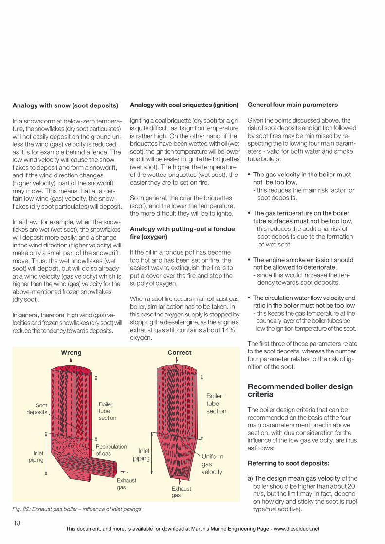
Another factor that can reduce the ac-tual gas velocity in a specific part of theboiler is the design of the inlet piping tothe boiler. It is thus not only the actualmean gas velocity through the boiler thatis the decisive factor for soot deposits.It is in fact the boiler’s lowest gas velocitythat is decisive, as illustrated by the ex-ample below.
In one case, a smoke tube boiler sufferedfrom soot clogging caused by a non-uniform gas flow due to a 90° bend just be-fore the inlet to the boiler, see Fig. 22,left. Clogging with dry, hard and consis-tent soot only occurred in that corner ofthe boiler, with the low gas velocity. Noprob- lems were experienced on sisterships with the same main engine andboiler types, but with a long straight in-let pipe to the boiler, see Fig. 22, right.
Summary of main reasons forsoot fires
Given the points discussed in this pa-per, and with due consideration for thestatistical material and the warning tri-angle for soot fires (Fig. 2), a generaland fairly simple explanation of the mainreasons for soot fires may now be givenby using the analogies below.
Fig. 21: Boiler trouble – influence of water circulation in water tubes
20
15
10
5
0
Number of cases
Number of cases
15
10
5
0
0 1 2 3 4 5 6 7 8 9Water inlet velocity to boiler m/s
0 2 4 6 8 10 12
Trouble
No trouble
Circulation water/steam flow ratio (normal service)
This document, and more, is available for download at Martin's Marine Engineering Page - www.dieselduck.net
18
Analogy with snow (soot deposits)
In a snowstorm at below-zero tempera-ture, the snowflakes (dry soot particulates)will not easily deposit on the ground un-less the wind (gas) velocity is reduced,as it is for example behind a fence. Thelow wind velocity will cause the snow-flakes to deposit and form a snowdrift,and if the wind direction changes(higher velocity), part of the snowdriftmay move. This means that at a cer-tain low wind (gas) velocity, the snow-flakes (dry soot particulates) will deposit.
In a thaw, for example, when the snow-flakes are wet (wet soot), the snowflakeswill deposit more easily, and a changein the wind direction (higher velocity) willmake only a small part of the snowdriftmove. Thus, the wet snowflakes (wetsoot) will deposit, but will do so alreadyat a wind velocity (gas velocity) which ishigher than the wind (gas) velocity for theabove-mentioned frozen snowflakes(dry soot).
In general, therefore, high wind (gas) ve-locities and frozen snowflakes (dry soot) willreduce the tendency towards deposits.
Analogy with coal briquettes (ignition)
Igniting a coal briquette (dry soot) for a grillis quite difficult, as its ignition temperatureis rather high. On the other hand, if thebriquettes have been wetted with oil (wetsoot), the ignition temperature will be lowerand it will be easier to ignite the briquettes(wet soot). The higher the temperatureof the wetted briquettes (wet soot), theeasier they are to set on fire.
So in general, the drier the briquettes(soot), and the lower the temperature,the more difficult they will be to ignite.
Analogy with putting-out a fonduefire (oxygen)
If the oil in a fondue pot has becometoo hot and has been set on fire, theeasiest way to extinguish the fire is toput a cover over the fire and stop thesupply of oxygen.
When a soot fire occurs in an exhaust gasboiler, similar action has to be taken. Inthis case the oxygen supply is stopped bystopping the diesel engine, as the engine’sexhaust gas still contains about 14%oxygen.
General four main parameters
Given the points discussed above, therisk of soot deposits and ignition followedby soot fires may be minimised by re-specting the following four main param-eters - valid for both water and smoketube boilers:
• The gas velocity in the boiler mustnot be too low,- this reduces the main risk factor for soot deposits.
• The gas temperature on the boilertube surfaces must not be too low,- this reduces the additional risk of soot deposits due to the formation of wet soot.
• The engine smoke emission shouldnot be allowed to deteriorate,- since this would increase the ten- dency towards soot deposits.
• The circulation water flow velocity andratio in the boiler must not be too low- this keeps the gas temperature at the boundary layer of the boiler tubes be low the ignition temperature of the soot.
The first three of these parameters relateto the soot deposits, whereas the numberfour parameter relates to the risk of ig-nition of the soot.
Recommended boiler designcriteria
The boiler design criteria that can berecommended on the basis of the fourmain parameters mentioned in abovesection, with due consideration for theinfluence of the low gas velocity, are thusas follows:
Referring to soot deposits:
a) The design mean gas velocity of theboiler should be higher than about 20m/s, but the limit may, in fact, dependon how dry and sticky the soot is (fueltype/fuel additive).Fig. 22: Exhaust gas boiler – influence of inlet pipings
Wrong Correct
Boilertubesection
Inletpiping
Exhaustgas
Recirculationof gas
Sootdeposits
Boilertubesection
Inletpiping Uniform
gasvelocity
Exhaustgas
This document, and more, is available for download at Martin's Marine Engineering Page - www.dieselduck.net
19
b)The pinch point temperature of theboiler should be higher than about15°C or, even better, 20°C.
c)The boiler’s exhaust gas outlet tem-perature should not be lower thanabout 165°C as otherwise condensa-tion of sulphuric acid in the exhaustgas could make the soot sticky.
d)The inlet piping to the boiler shouldbe designed so that the gas flow ve-locity distribution is as uniform as pos-sible, in order to avoid local pointswith a particularly low gas velocity.
e)The exhaust gas design pressureloss across the boiler should be ashigh as possible - increasing the gasvelocity in the boiler. This means thatthe pressure losses in the remainingparts of the exhaust gas systemshould be dimensioned as low aspossible (large pipe diameters).
f) A dumping condenser should be in-stalled to control steam production/consumption.A gas by-pass valve installed to con-trol the steam production would reducethe gas velocity in the boiler - andconsequently increase the risk of sootdeposits - and cannot, therefore, berecommended.
The supplementary recommendationsbelow apply only to boilers of the watertube type:
g)A by-pass duct with an automaticallyoperated on/off valve (open/closed at50% SMCR) may in certain operatingconditions be recommended for wa-ter tube boilers. If, for example, theship is often slow steaming, i.e. thediesel engine operates at low load,such an installation will prevent sootdeposits on the boiler tubes by by-passing all the gas and thereby avoid-ing low gas velocities and the associ-ated risk of soot deposits in the boiler.
h)Automatic soot blowers for frequentcleaning should be installed in watertube boilers in order to clean the tubesof soot. The pressure of the soot blowingmedium should be as high as possibleduring the entire soot blowing sequence.As the possible steam pressure usedis only about 7 barg, and in some cases6 barg, the use of high-pressure air willbe better.
i) Fixed water washing system and/ormanual cleaning at regular intervals.Water washing is performed in orderto clean the boiler completely of sootwhich has not been cleaned away bythe soot blowers. The exhaust gaspiping between engine and boiler shouldbe so arranged that the boiler can becleaned more thoroughly from time totime when the engine is stopped inharbour without the risk of flooding theengine/turbochargers with cleaning fluid.Water washing should preferably beundertaken while the tubes are stillhot, making it easier to remove thesoot as it will “crack”.
If the above-mentioned on/off exhaustbypass is installed, the boiler can bebypassed. Water washing shouldthen also be carried out during seaservice as often as possible (when theexhaust pressure loss increases), andnot only during stops in harbour. Afterwater washing, it should be checkedthat no soot is left, as remaining wetsoot may increase the risk of soot de-posits when continuing operation.
j) The water circulation temperature atthe boiler inlet, for boilers with apreheater section, should be higherthan about 140°C as otherwise toolow temperatures could cause someof the gas constituents, such as fueland lube oil vapour, to condense onthe cold boiler tube surfaces, and thiscould increase the tendency towardssoot deposits.
Another advantage of this is that thetemperature of the preheater tube
surfaces can then be higher than thedew point of the sulphuric acid in thegas, thus minimising the risk ofsulphuric acid corrosion.
Referring to ignition:
k)The circulation water flow velocityand ratio at the boiler inlet should beas high as possible in order to keepthe gas temperature at the boilertube surface as low as possible (incontrast to point j). The water flow ra-tio (water flow/steam production ratio)is recommended to be equal to orhigher than 6. This should reduce therisk of ignition of possible soot depos-its, which can happen at tempera-tures above some 150°C and, underextreme conditions, even as low as120°C.
It is therefore also very important toensure the best suction conditions sothat cavitation does not occur in thecirculating pumps under any workingconditions, as otherwise the circulat-ing water flow could be reduced oreven stopped.
A temperature monitoring systemmounted above the boiler might be rec-ommendable as a means of detecting afire in the boiler as soon as it starts.
Recommended operatingconditions
In view of the damage that can becaused by an extensive soot fire in theexhaust gas boiler, it is recommended,during the operation of the ship, to givedue consideration to the following:
Normal operating conditions
a)Soot-blowingIf soot-blowing equipment is installed,we recommend checking its effi-ciency and adjusting the number ofdaily soot-blowings accordingly.
This document, and more, is available for download at Martin's Marine Engineering Page - www.dieselduck.net
20
b)Preheated feed water during start-upIn order to avoid the condensation ofsome of the gas constituents, pre-heated feed water should always beused (temperature higher than about140°C) during start-up and during lowload operation, especially if the boileris not fitted with an on/off by-passduct/valve which can be activated inthese running conditions.
c)Water circulation, correct functioningIt should be ascertained that theboiler’s water circulation system andits control system are functioningproperly.
d)Water circulation after engine stopAfter the engine is stopped, the boiler’swater circulating pump should be keptrunning until the boiler temperature hasfallen below 120°C, because wet oilysoot may catch fire at temperaturesas low as this.
On the other hand, it is recommendednot to stop the circulating pump inharbour unless the boiler has beenchecked and is clean.
e)Heavy smoke from engineIf excessive smoke is observed, eitherconstantly or during acceleration, thisis an indication of a worsening of thesituation. The cause should be identi-fied and remedied. Excessive smokecould be caused by defective fuelvalves, a jiggling governor, incorrectadjustment of the governor fuel limiter,or the malfunctioning of one (of two)auxiliary blowers, etc.The boiler should be checked andcleaned if necessary.
Operating conditions in waterleakage situations
DnV recently informed about a casewhere a water leakage was discoveredfrom a water tube type exhaust gas boilerRef. [6]. In order to get to port, the watercirculation was shut off. When arriving
at anchorage, the exhaust gas boiler over-heated, and the crew found that a hightemperature soot fire had occurred.
The above case shows how important itis to cool the tubes, i.e. that the watercirculating through the tubes always func-tions correctly, in order to avoid ignition ofthe soot.
In this case, the water circulation couldnot continue because of the waterleakage. Therefore, in such a situationthe below actions are recommended.
Actions to be taken prior to dry running:a)When shutting off the water circula-
tion, the main engine should also beshut down so that the exhaust gasboiler can cool down and any smoul-dering of soot deposits on the boilertubes can die out.
b)The heating surface should be in-spected carefully for soot deposits,and water washing performed, bothfor cleaning and cooling.
c)Make every effort to re-establish thewater circulation to the boiler andthereby reduce the dry running periodto a minimum.
d)Boiler manufacturers allow dry run-ning of exhaust gas boilers only in thecase of emergency and with a cleanboiler. In addition they emphasize thatevery possible precaution must beobserved to prevent soot fire.
Actions to be taken during dry running:e) Increase the frequency of soot blow-
ing considerably, and perform sootblowing several times prior tomanoeuvring.
f) Inspect the boiler frequently and, ifany soot is present, then water washthe boiler and increase the soot blow-ing frequency.
g)The boiler’s instruction manual mustbe read carefully and its instructionsare always to be followed.
Operating in soot fire situations
On the other hand, if a soot fire doesstart after all, we recommend either ofthe following two types of measures,depending on the level of fire:
Fire level 1, where an initial soot firehas just been discovered:
a) Stop the main engine, and thereby the oxygen supply to the fire.
b) Continue operating the water circulating pump.
c) Never use soot blowers for fire fighting, as air will feed the fire with oxygen, and steam will involve a risk of high temperature fire.
d) Stop the air circulation through the engine, and thereby the air supply to the fire, i.e. keep air pressure on the diesel engine’s exhaust valve closing mechanism (closed valves).
e) Water washing, if fitted, may be used to extinguish the fire. This is normally connected to the ship’s fire fighting water system.
In a well-run plant any fire that startswill be small, and if the above emer-gency action is taken immediately, thefire will be damped down quickly, andwater circulated by the pump will helpkeep the tubes cool and reduce anyheat damage caused by the fire, Ref. [2].
If the soot fire has turned into an ironfire, this can be indicated by a loss ofwater, for example, if the feed waterconsumption increases very much and/or if a low level alarm in the steamdrum is activated. A temperature sen-sor (normally max. 400°C) will not nor-mally be able to measure the high tem-peratures.
This document, and more, is available for download at Martin's Marine Engineering Page - www.dieselduck.net
21
Fire level 2, where boiler tubes havemelted down:
a) Stop the main engine, if it is notstopped already.
b) Stop the circulating water pump.
c) Close valves on the water circulation line.
d) Discharge the (remaining) water from the exhaust gas boiler sections.
e) Cool down with plenty of splash water directly on the heart of the fire.
DnV warns that, if a soot fire has turnedinto a high-temperature fire (hydrogen/iron fire), care should be taken whenusing water for extinguishing, otherwise,the fire may become worse unless largeamounts of water are applied directly tothe heart of the fire. The main aim, whenone discovers an initial small fire, is to pre-vent it turning into a high-temperature fire.
Closing Remarks
In principle, the most efficient exhaustgas waste heat recovery system willcontribute to the best overall economyon the ship provided, of course, that therecovered heat, for example in the formof steam, is needed on board the ship.
Normally, the exhaust gas boiler designwill be based on a steam productionrequirement related to the rather highsteam consumption needed in extremewinter conditions.
On the other hand, when the ship op-erates worldwide in normal trades, thissituation may occur only a few days ayear. The choice of a smaller boiler, withlower design steam production, maytherefore mean few disadvantages,provided the steam requirement fornormal sea service can be met.
One advantage of this will be that thedesign gas velocity through the smallerboiler will be higher and, as explained inthis paper, this will reduce the risk ofsoot deposits and fires.
As an additional advantage, the exhaustgas boiler will be cheaper.
A boiler and system design based onthe correct criteria will reduce the riskof soot deposits and fires in exhaustgas boilers. The use of such criteria istherefore very important and couldprobably be introduced with advantageinto the recommendations of the Classi-fication Societies. This would also allowboiler makers to offer boilers on equallycompetitive conditions (by, for example,specifying automatic soot blowers inwater tube boilers).
The use of special fuel additives withiron oxide seems to reduce the sticki-ness of the soot and may be useful incases where the exhaust gas boilersare vulnerable to soot deposits (for ex-ample large capacity boilers).
The statistical material from DnV (Fig. 1)shows a considerable reduction in sootfire cases from 1998 to 2003, but alsoindicates that great attention to installa-tion and operation of exhaust gas boil-ers is still needed
References
[1] News from Det norske Veritas (DnV), March 1993 and 2004
[2] Aalborg Boilers, Instruction K. 7400.2, Water Tube Boilers with Gilled Tubes for Exhaust Gas, Type AV-6N, Operation and Maintenance
[3] Sunrod Exhaust Gas Economizers (brochure, 1992)
[4] Guide to Prevention of Soot Fire on Exhaust Gas Economizers (in Japanese) 1992, Nippon Kaiji Kyokai, Tokyo
[5] Operation on Heavy Residual Fuels, MAN B&W Diesel A/S, CopenhagenDenmark, March 2003
[6] Casualty Information from DnV, No. 3, June 2003
This document, and more, is available for download at Martin's Marine Engineering Page - www.dieselduck.net