Instructions 95-8470-05 Eagle Quantum ™ Fire and Gas Detection/Releasing System Detector Electronics Corporation 6901 West 110th Street • Minneapolis, Minnesota 55438 USA Tel: 952.941.5665 or 800.765.3473 • Fax: 952.829.8750 10/01 95-8470-05
Transcript
Instructions 95-8470-05
Eagle Quantum™
Fire and Gas Detection/Releasing System
Detector Electronics Corporation6901 West 110th Street • Minneapolis, Minnesota 55438 USATel: 952.941.5665 or 800.765.3473 • Fax: 952.829.8750 10/01 95-8470-05
Section I - System OverviewSYSTEM DESCRIPTION.......................................................I-1SYSTEM FEATURES ............................................................I-2MAJOR COMPONENT DESCRIPTIONS ..............................I-2
Intelligent Field Devices on Local OperatingNetwork/Signaling Line Circuit (LON™/SLC) .......I-2
Local Control Unit (LCU) ..............................................I-2Local Output Unit (LIOU)..............................................I-3
THEORY OF OPERATION ....................................................I-3NETWORK OPERATION DURING A FAULT CONDITION...I-3
Multiple Wiring Faults ...................................................I-4LON/SLC Ground Fault Detection and LCU
Protection..............................................................I-4Field Devices without Power ........................................I-4
Section II - Local Control Unit and Power SuppliesOVERVIEW...........................................................................II-1
EQ21XXPS SERIES POWER SUPPLIES AND EQ2100PSM POWER SUPPLY MONITOR .........................II-8
Features ......................................................................II-8Description ..................................................................II-8EQ2100PSM ...............................................................II-8EQ2200IDCGF ............................................................II-8
Section III - Local Output UnitOVERVIEW..........................................................................III-1
Enclosure ...................................................................III-1Fault LED and Reset Switch ......................................III-1
EQ2200DCU AND EQ2200DCUEX DIGITALCOMMUNICATION UNIT ...........................................IV-7Description..................................................................IV-7
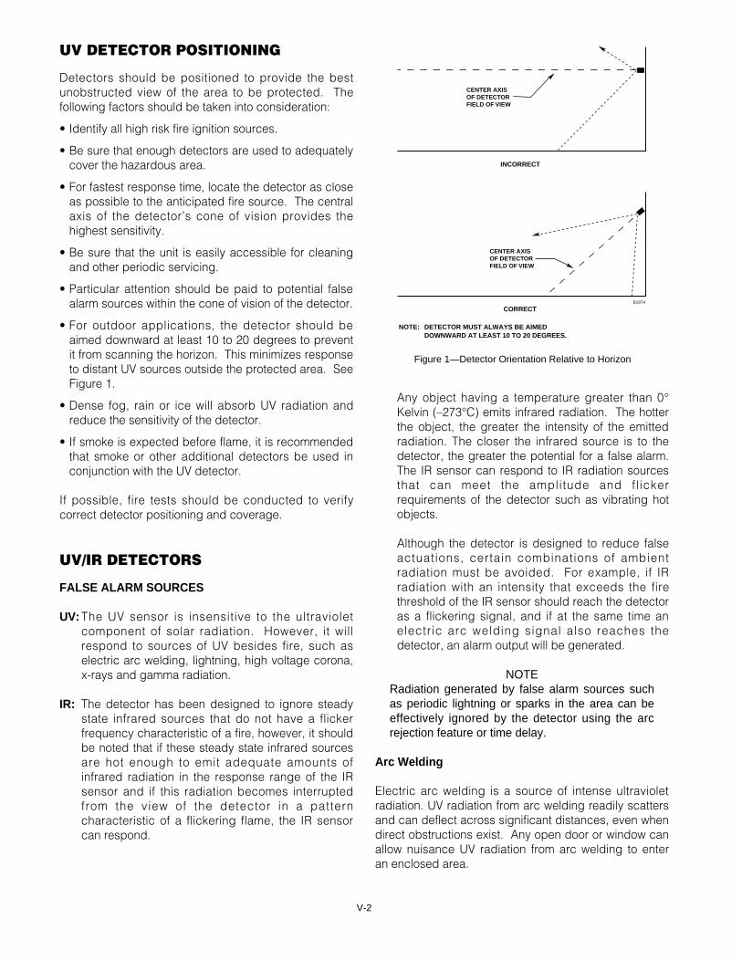
UV/IR DETECTOR POSITIONING.......................................V-3GAS DETECTOR POSITIONING.........................................V-3CATALYTIC GAS SENSORS...............................................V-4
Catalytic Sensor Operation.........................................V-4Sensitivity Loss in Catalytic Combustible Gas
Sensors ...............................................................V-6Calibration Gas ...........................................................V-7
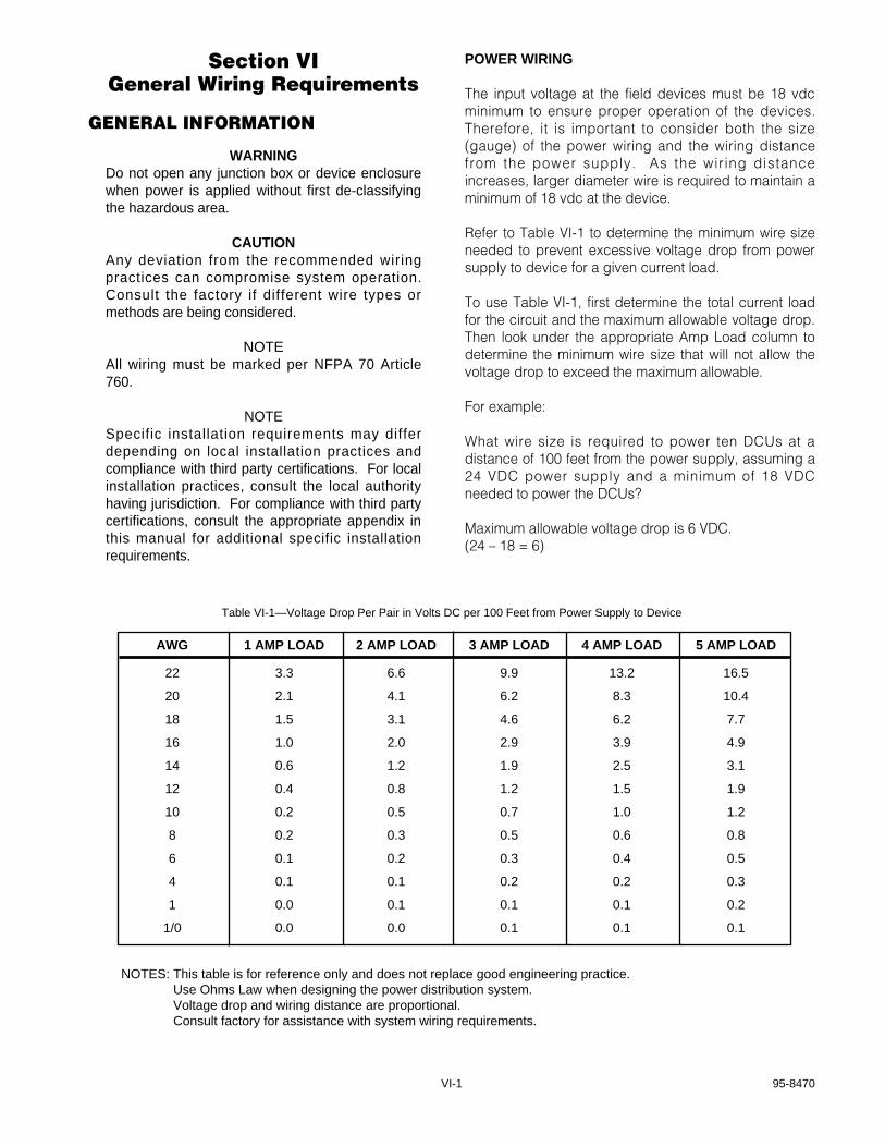
Section VI - General Wiring RequirementsGENERAL INFORMATION .................................................VI-1
Power Wiring .............................................................VI-1Network Wiring ..........................................................VI-2Shield Grounding .......................................................VI-2Junction Box Grounding ............................................VI-3RS-485 Link Wiring....................................................VI-3Protection Against Moisture Damage ........................VI-3Electrostatic Discharge ..............................................VI-3
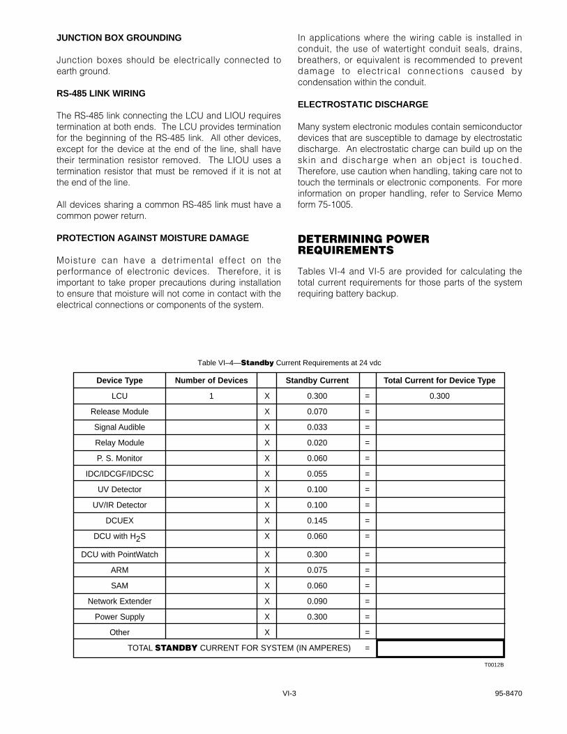
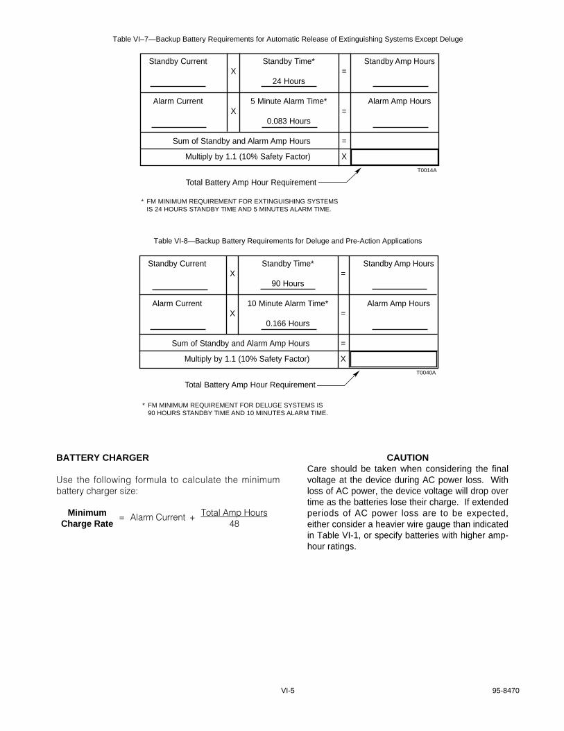
DETERMINING POWER REQUIREMENTS .......................VI-3EQ2110PS, EQ2130PS AND EQ2175PS .................VI-4Backup Battery ..........................................................VI-4Battery Charger .........................................................VI-5
Table of Contents
Section VII – System WiringEQ2100PSM POWER SUPPLY MONITOR USED WITHEQ2110PS, EQ2130PS AND EQ2175PS POWER SUPPLIES............................................................VII-1
Wiring........................................................................VII-1Startup ......................................................................VII-3Measuring Battery Voltage and Charging Current ....VII-3
EQ2100LCU SERIES LOCAL CONTROL UNIT ................VII-4EQ2100LIOU LOCAL OUTPUT UNIT ................................VII-7
Backplane Wiring......................................................VII-7RS485 Link Wiring ....................................................VII-7Power Wiring ............................................................VII-7
SIGNAL AUDIBLE MODULE............................................VII-11Wiring......................................................................VII-11Jumpers/Switches...................................................VII-11Address Switch Setting...........................................VII-11
FIELD DEVICES...............................................................VII-13EQ2200IDC Series Initiating Device Circuit ............VII-13EQ2200IDCGF Series Initiating Device Circuit
Ground Fault ...................................................VII-14EQ2200IDCSC Series Initiating Device
Circuit Short Circuit .........................................VII-14EQ2200UV UV Flame Detector ..............................VII-15EQ2200UVHT High Temperature UV Detector.......VII-17EQ2200UVIR UV/IR Flame Detector ......................VII-19EQ2200DCU Digital Communication Unit
used with Det-Tronics H2S/O2 Sensors or other Two-Wire 4 to 20 ma Devices............VII-22
Sensor Separation for DCU with H2S and O2 Sensors .....................................................VII-22
EQ2200DCU Digital Communication Unit used with PointWatch......................................VII-23
EQ2200DCUEX Digital Communication Unit used with Det-Tronics Combustible Gas Sensors...............................VII-24
EQ2500ARM Series Agent Release Module ..........VII-27EQ2500SAM Series Signal Audible Module ...........VII-29EQ2400NE Series Network Extender .....................VII-30
Section IX – System StartupPRE-COMMISSIONING CHECKLIST .................................IX-1STARTUP PROCEDURE ....................................................IX-2CALIBRATION.....................................................................IX-2
Calibration Algorithm A For Manual Calibration of Universal DCU................................................IX-2
Calibration Algorithm C For Combustible Gas DCUs and Automatic Calibration of Universal DCUs....IX-4
Calibration Algorithm D For Universal DCUs with O2 Sensor...................................................IX-5
Calibration Algorithm G For DCUs with PointWatch..IX-6UV DETECTOR TEST.........................................................IX-7
Fire Alarm Test ..........................................................IX-7False Alarm Test........................................................IX-7
UV/IR DETECTOR TEST ....................................................IX-7Manual oi...................................................................IX-8Automatic oi ..............................................................IX-8
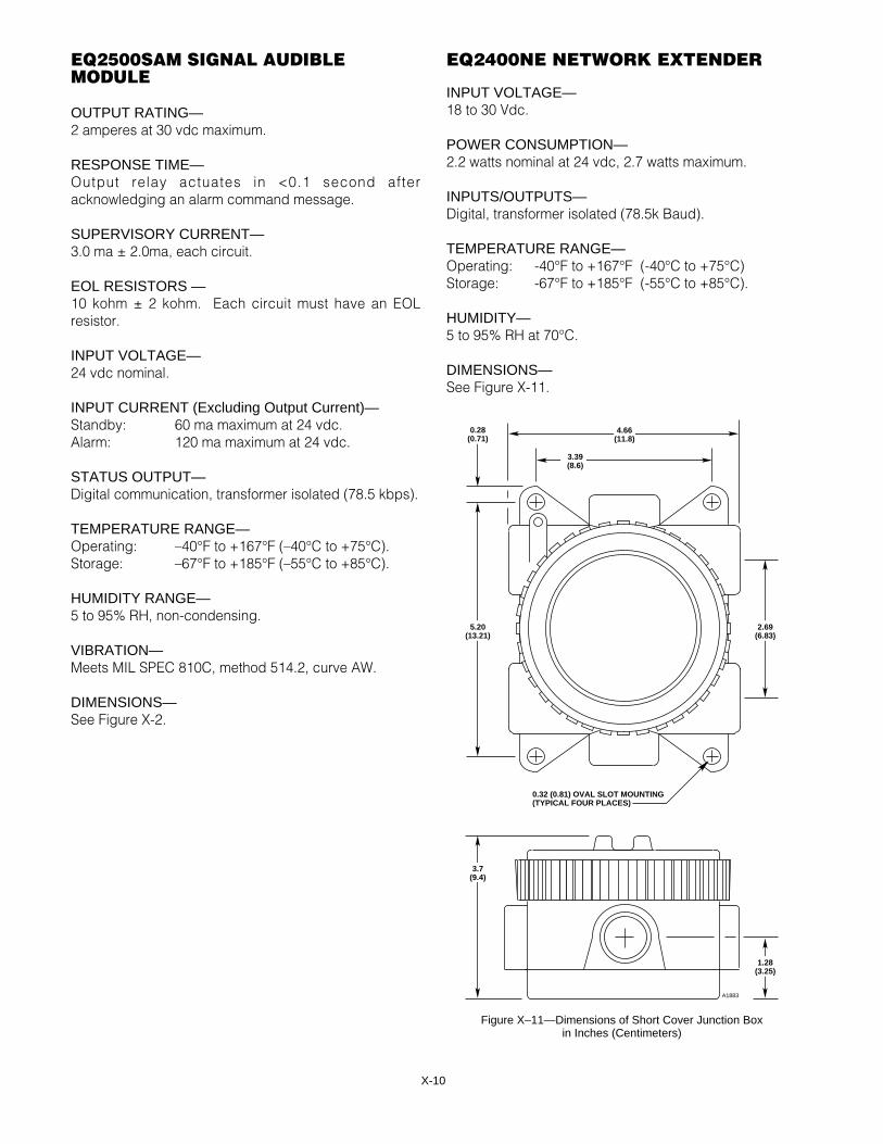
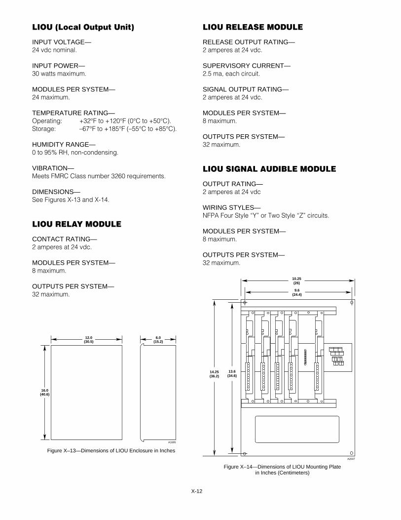
Section X – SpecificationsCERTIFICATIONS................................................................X-1EQ2100LCU LOCAL CONTROL UNIT.................................X-1EQ2200IDC/IDCGF/IDCSC INITIATING DEVICE CIRCUIT X-3EQ2200UV and EQ2200UVHT UV FLAME DETECTORS ..X-3EQ2200UVIR UV/IR DETECTOR.........................................X-6EQ2200DCU AND EQ2200DCUEXDIGITAL COMMUNICATION UNIT ......................................X-9EQ2500ARM AGENT RELEASE MODULE .........................X-9EQ2500SAM SIGNAL AUDIBLE MODULE........................X-10EQ2400NE NETWORK EXTENDER..................................X-10EQ2100PSM POWER SUPPLY MONITOR .......................X-11EQ2110PS, EQ2130PS AND EQ2175PSPOWER SUPPLIES............................................................X-11LIOU Local Output Unit.......................................................X-12LIOU RELAY MODULE ......................................................X-12LIOU RELEASE MODULE .................................................X-12LIOU SIGNAL AUDIBLE MODULE ....................................X-12COMBUSTIBLE GAS SENSOR .........................................X-13ELECTROCHEMICAL SENSORS......................................X-13POINTWATCH....................................................................X-13
Section XI – System MaintenanceROUTINE MAINTENANCE .................................................XI-1
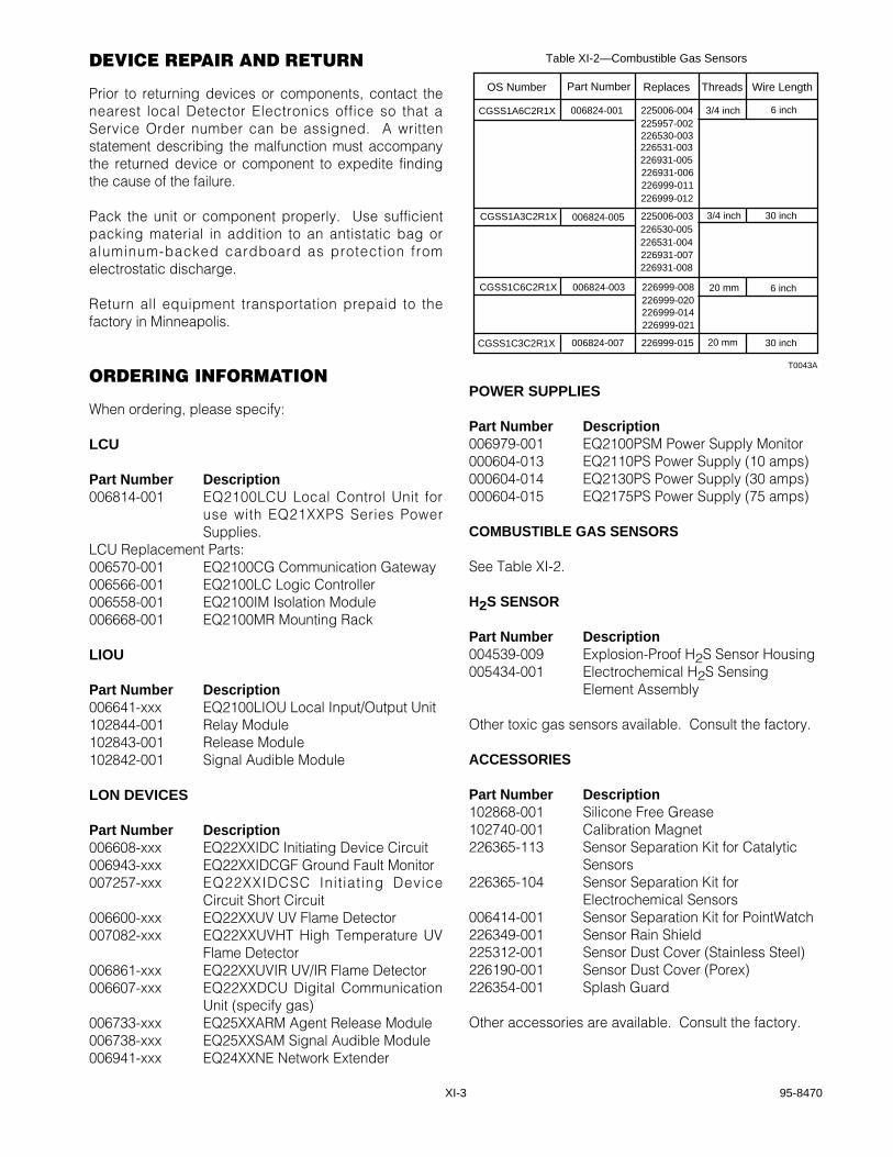
TROUBLESHOOTING.........................................................XI-2REPLACEMENT PARTS.....................................................XI-2DEVICE REPAIR AND RETURN ........................................XI-3ORDERING INFORMATION ...............................................XI-3
Table of Contents – Continued
IMPORTANTBe sure to read and understand the entireinstruction manual before installing or operating theEagle Quantum System. Only qualified personnelshould install, maintain or operate the EagleQuantum System.
WARNINGThe hazardous area must be de-classified prior toremoving a junction box cover or opening adetector assembly with power applied.
CAUTION1. The wiring procedures in this manual are
intended to ensure proper functioning of thedevices under normal conditions. However,because of the many variations in wiring codesand regulations, total compliance to theseordinances cannot be guaranteed. Be certainthat all wiring complies with the NEC as well asall local ordinances. If in doubt, consult aqualified official before wiring the system.
2. Some Eagle Quantum devices containsemiconductor devices that are susceptible todamage by electrostatic discharge. Anelectrostatic charge can build up on the skin anddischarge when an object is touched. Alwaysobserve the normal precautions for handlingelectrostatic sensitive devices, i.e. use of a wriststrap (if available) and proper grounding.
3. To prevent unwanted actuation, alarms andextinguishing devices must be secured prior toperforming system tests.
Section I System Overview
SYSTEM DESCRIPTION
The Eagle Quantum System serves multiple roles in themonitoring and protection of hazardous areas. It is a“fire detection and extinguishing agent release system”combined with a “hazardous gas monitoring system,”integrated on a fault tolerant digital communicationnetwork. The Eagle Quantum system uti l izes anadvanced distributed architecture that is equally adeptat monitoring analog process signals like combustibleor toxic gas concentrations, and discrete “contactclosure” type devices such as manual fire alarm “callboxes” and heat detectors, as well as Det-Tronicsoptical flame detection. This sensor information is thentransmitted to the control unit to execute the firesuppression logic, to control agent release, signaling,and annunciation outputs, and to communicate withexternal operator interface systems for configurationand monitoring.
*oi is Detector Electronics' Trademark for its patented OpticalIntegrity Systems, U.S. Patent 3,952,196, United Kingdom Patent1,534,969, Canada Patent 1,059,598.
I–2
SYSTEM FEATURES
• Deluge and pre-action release capability for firesuppression.
• Agent release capability for fire suppression.
• Up to 244 addressable field devices and 32,500 feet(10,000 meters) of wiring on the network.
• Supports up to 6 network extenders.
• Compatible with Det-Tronics flame and gas detectors.
• Accommodates a variety of third-party devices with 4to 20 ma or “dry contact” type inputs.
• Fault tolerant communication loop.
• Non-volatile memory for alarm and calibration logging.
• Built in diagnostics.
• Programmable logic.
• Modbus RTU Master/Slave and Allen Bradley DF1communication capability through two electricallyisolated RS-232 serial ports.
• Up to 4 gateways and 4 logic controllers.
• Up to 75 amperes of alarm current per power supply.
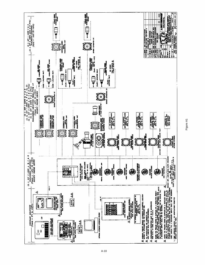
• FM Approved to ANSI/NFPA-72-1996 National FireAlarm Code. See Figure A1 in Appendix A forinstallation requirements.
• FM, CSA, CENELEC and CE Mark Certifications. SeeAppendix A, B and C respectively for details andspecific installation requirements.
MAJOR COMPONENT DESCRIPTIONS
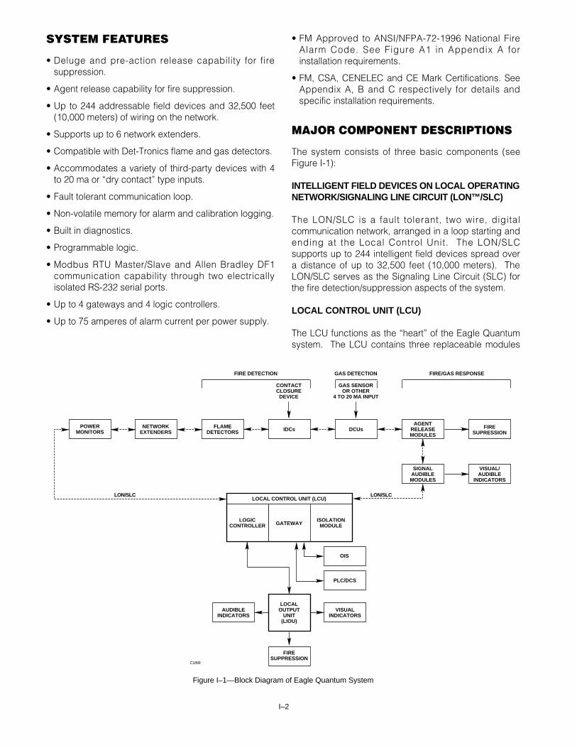
The system consists of three basic components (seeFigure I-1):
INTELLIGENT FIELD DEVICES ON LOCAL OPERATINGNETWORK/SIGNALING LINE CIRCUIT (LON™/SLC)
The LON/SLC is a fault tolerant, two wire, digitalcommunication network, arranged in a loop starting andending at the Local Control Unit. The LON/SLCsupports up to 244 intelligent field devices spread overa distance of up to 32,500 feet (10,000 meters). TheLON/SLC serves as the Signaling Line Circuit (SLC) forthe fire detection/suppression aspects of the system.
LOCAL CONTROL UNIT (LCU)
The LCU functions as the “heart” of the Eagle Quantumsystem. The LCU contains three replaceable modules
FIRE DETECTION
C1899
PLC/DCS
OIS
LOCALOUTPUT
UNIT(LIOU)
AUDIBLEINDICATORS
VISUALINDICATORS
FIRESUPPRESSION
GATEWAYLOGIC
CONTROLLERISOLATION
MODULE
LOCAL CONTROL UNIT (LCU)
FLAMEDETECTORS IDCs DCUs
AGENTRELEASEMODULES
FIRESUPRESSION
SIGNALAUDIBLEMODULES
VISUAL/AUDIBLE
INDICATORS
FIRE/GAS RESPONSEGAS DETECTION
CONTACTCLOSURE
DEVICE
GAS SENSOROR OTHER
4 TO 20 MA INPUT
NETWORKEXTENDERS
POWERMONITORS
LON/SLC LON/SLC
Figure I–1—Block Diagram of Eagle Quantum System
that perform all the communication, command, andcontrol functions for the system. It includes all therequired operator interface controls for a fire alarmsystem (silence, acknowledge, reset, isolate),annunciation relays, a local information display, andcommunication interfaces for computer basedconfiguration and monitoring of the system.
LOCAL OUTPUT UNIT (LIOU)
The LIOU consists of a rack controlled by the LCU thatcan hold up to six FenwalNet 2000 modules. Thesemodules allow the control of Notification ApplianceCircuits (NACs), fire suppression agent release (CO2,Halon, FM200) using supervised relays, as well asunsupervised relays for other needs.
THEORY OF OPERATION
During normal operation, each node on the networkmonitors its attached sensor or other input, determines ifit has an alarm condition, analyzes its own health,checks network integrity, and then packages up thisinformation for transmission to the communicationgateway, located in the LCU. This Standard PeriodicReport (SPR) contains 16 pieces of “discrete”information on the status of the node and, whereapplicable, also contains the analog value of its sensor.At the time of node configuration, the report rate of theSPR can be set to anywhere between 1 and 10seconds.
In the LCU the Communication Gateway collects all ofthe incoming SPRs from the field devices and puts theinformation into “datatables.” Datatables are organizedareas of memory in the gateway that can be “read” byexternal “host devices” using one of the gateway’s serialports. If any of the SPRs indicate an out of tolerancecondition, the gateway will display this information on itsintegrated faceplate display. The gateway also has fourprogrammable relays whose action can beprogrammed to events in the SPRs of the monitorednodes.
In addition to SPRs, nodes used as a part of the firedetection and suppression system, such as f iredetectors or Initiating Device Circuits (IDCs) interfacedwith heat detectors, manual call points, etc. send aseparate Standard Supervisory Report (SSR) to theLogic Controller, located in the Local Control Unit. TheLogic Controller, which manages the fire suppressionlogic, uses these SSR messages to verify that the nodesused in the fire alarm and suppression logic are activeand able to communicate. If the Logic Controller doesnot receive SSRs from a required node, it wil lannunciate a “trouble” condition.
If a “Fire Alarm” is detected by a Flame Detector orInitiating Device Circuit (IDC), the affected node willsend a special Acknowledged Exception Report (AER)directly to the Logic Controller. The AER is transmittedas soon as an alarm is detected to maximize systemperformance. When the Logic Controller receives theAER, it sends the originating node a messageacknowledging its receipt. If the node originating theAER does not receive an acknowledgement, it will re-transmit the AER until it receives an acknowledgement.This exchange of messages is used to ensure thatcritical messages are received at all appropriateregisters throughout the system.
Once the Logic Controller receives a Fire Alarmmessage from a field device, “fixed logic” will activatebuilt-in annunciation circuits, which consist of both avisible and audible alarm. The “programmable logic”will execute any specified voting, timing, and/or zonelogic and subsequently activate the appropriate outputcircuits for Notification Appliance Circuits (NACs), agentrelease circuits, and unsupervised relay outputs.
The faceplate of the Logic Controller has twopushbuttons. “ACKNOWLEDGE” will silence the built inaudible alarm and illuminate the “Acknowledge LED”located on the faceplate next to the “Acknowledge”pushbutton. “SILENCE” will silence selected NACs inthe field and illuminate the “Silence LED” located on thefaceplate next to the “Silence” pushbutton. The LogicController also features a keyswitch to reset the systemafter the event is over.
NETWORK OPERATION DURING AFAULT CONDITION
The Eagle Quantum system utilizes a unique patentedtechnique for detecting problems in the communicationnetwork wiring. This state-of-the-art feature minimizesthe possibility of a communication breakdown in theevent of a wiring fault in the communication loop andcan also serve as an aid in troubleshooting.
The communication network is constructed as a loopthat starts and ends at a pair of communication portslocated at the LCU. The nodes communicate with theLCU over the LON/SLC as shown in Figure I-2.
Each field device node contains both the hardware andsoftware necessary to isolate and re-routecommunication in the event of a network wiring fault.When a problem occurs somewhere within the networkwiring, the communication gateway located in the LCUannunciates the fault, while the fault isolation circuitry inthe affected nodes isolates the section of the networkwhere the fault has occurred. Communication is
I–3 95-8470
thereby ensured and will continue over the network.See Figure I-3.
A single open or short on the LON/SLC will not affectsystem communication between the field devices andthe gateway. System communication will continue untilthe wiring problem can be repaired.
MULTIPLE WIRING FAULTS
In the event of multiple wiring faults on the LON/SLC,the nodes between the faults will continue to function,but the faults will prevent them from communicating withthe gateway. See Figure I-4. In this example, nodes 1to 4 communicate using one gateway port (path A) andnodes 7 and 8 use the other gateway port (path B).Nodes 5 and 6 are unable to report to the gatewaybecause they are isolated by the two wiring faults.
LON/SLC GROUND FAULT DETECTION AND LCUPROTECTION
The LCU contains an isolation module that checks theLON/SLC for ground faults. Should a ground fault bedetected, it is indicated by an LED on the isolationmodule’s faceplate. The isolation module also ensurescommunication with the field devices even if there is aLON/SLC short circuit directly adjacent to the LCU.
FIELD DEVICES WITHOUT POWER
All Eagle Quantum field devices are designed so that a“pass-through” circuit is created for the network wiringon a loss of power to the node. This ensures networkintegrity even when a node is down for service or hasbeen damaged. The Communication Gateway in theLCU wil l report powered-down nodes as “not-communicating.”
IMPORTANTSince it is impossible to predict where a networkfault might occur or exactly what effect it will haveon actual system operation, it is important todiagnose and repair any fault as soon as possibleafter it is detected to ensure reliable systemoperation.
I–4
A1851
NODE 1 NODE 8
NODE 3 NODE 6
NODE 2 NODE 7
NODE 4 NODE 5
LCU
Figure I–2—Normal Communication over the Digital Highway
A1852
LCUNODE 1 NODE 8
NODE 3 NODE 6
NODE 2 NODE 7
NODE 4 NODE 5
PATH A PATH B
WIRING FAULT
Figure I–3—Communication with a Single Wiring Fault on the Network
A1853
LCUNODE 1 NODE 8
NODE 3 NODE 6
NODE 2 NODE 7
NODE 4 NODE 5
PATH A PATH B
WIRING FAULTS
Figure I–4—Communication with Multiple Wiring Faults on the Network
II–1 95-8470
Section IILocal Control Unit (LCU) and
Power Supplies
OVERVIEW
The Local Control Unit (LCU) is the “heart” of the EagleQuantum system. External host devices such as PLC’sor DCS’s interface through the LCU, the fire detectionand releasing logic resides in the LCU, control of thereleasing, signaling, and annunciation outputs arehandled by the LCU, and the Local OperatingNetwork/Signaling Line Circuit (LON/SLC), throughwhich all field devices communicate, starts and ends itsloop at the LCU. Physically, the LCU consists of a threeslot rack style enclosure that houses the CommunicationGateway, Logic Controller, and Isolation Module. Thesethree modules plug into the backplane and are securedwith thumb screws. All external wiring is routed throughconduit entries at the bottom and sides of the unit. Thewiring terminals are protected by a removable cover.The LCU can be installed in Class I, Division 2hazardous locations. Refer to Appendix A (FMRC) andAppendix B (CSA) for details.
LOGIC CONTROLLER
The Eagle Quantum Logic Controller uses sevenmicroprocessors and parallel processing techniques toexecute the logic used for fire suppression. Its wealthof logical operators allow for the easy development ofnearly any imaginable type of cross-zone monitoring,voting, and timed operations that might be needed in afire suppression system. The Logic Controller supportsANSI/NFPA 72 Class A, Style 7 communication with fielddevices.
COMMUNICATION GATEWAY
The Eagle Quantum Communication Gatewaycommunicates through two serial links for configurationand monitoring. This allows for device configurationusing a comprehensive set of Det-Tronics authoredsoftware tools. The monitoring is provided to theOperator Interface Station(s) (OIS) through Modbus orAllen-Bradley compatible protocols. The gateway alsoprovides four programmable relays that can be used toannunciate conditions being monitored by the deviceson the LON/SLC.
ISOLATION MODULE
The Isolation Module protects the integrity of theLON/SLC wiring by isolating shorts and monitoring forground faults. It also provides electrical isolation for thetwo serial communication ports between the gatewayand host devices.
OPTIONAL LCU VERSIONS
An optional EQ2101LCU is available with provisions fortwo 24 vdc power inputs. Two reliable and independent24 vdc supplies, in accordance with ANSI/NFPA 72section 1-5.2, must be supplied. If either of the suppliesis missing or a wiring problem occurs, a troublecondition will be annunciated.
Logic controllers can be added to the communicationnetwork to segment it into logical groups. Up to fourlogic controllers can be used on each network.
Auxiliary gateways can be added to provide additionalrelays or serial port connections to PLCs or DCSs. Up tothree auxiliary gateways can be added to the Quantumnetwork. Gateways located outside the LCU can beturned off without disrupting LON/SLC communicationwith the LCU.
EQ2100CG COMMUNICATIONGATEWAY
FEATURES
• Utilizes Modbus or Allen Bradley protocols
• Transformer isolation of network ports
• Four programmable relay outputs
• Three digit display and bar graph
• LEDs indicate relay status
• EMI/RFI hardened
DESCRIPTION
The Eagle Quantum Communication Gateway is used inconjunction with Det-Tronics software to configure thesystem as well as to provide information on an ongoingbasis to external systems such as PLCs and DCSs. Italso provides local display and four programmablerelay outputs. In addition, the gateway provides aheartbeat signal used to test for LON/SLC integrity, toprovide time and date information to field devices, andto monitor for the continued presence of all configuredfield devices.
The gateway receives and stores the current status andprocess variable information from all devices on the“Local Operating Network/Signaling Line Circuit”(LON/SLC) communication loop. It services all validrequests by Modbus RTU masters and/or Allen-BradleyDF1 masters that are received through its two hostinterface serial ports. When acting as a Modbus RTUmaster, the gateway will automatically transfer keyprocess variable and status information to a default oruser selected Modbus RTU slave address and registeroffset.
II–2
During normal operation the gateway produces aperiodic (250 millisecond) “heartbeat” signal on thenetwork, which is used by all field devices as a part oftheir network fault isolation routine. Every fourth“heartbeat” (1 second intervals) also includes a timeand date message that is used by the field devices forlogging calibration, alarm, and other events.
The gateway has sufficient non-volatile memory to storeconfiguration data for all networked field devices, whichis downloaded to the gateway from the OIS.
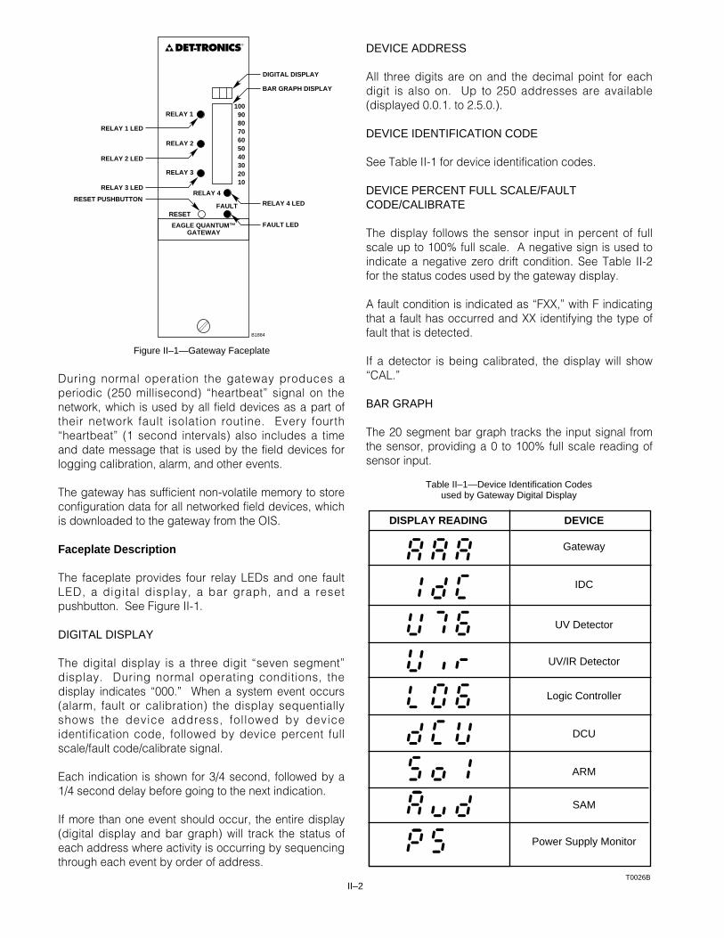
Faceplate Description
The faceplate provides four relay LEDs and one faultLED, a digital display, a bar graph, and a resetpushbutton. See Figure II-1.
DIGITAL DISPLAY
The digital display is a three digit “seven segment”display. During normal operating conditions, thedisplay indicates “000.” When a system event occurs(alarm, fault or calibration) the display sequentiallyshows the device address, fol lowed by deviceidentification code, followed by device percent fullscale/fault code/calibrate signal.
Each indication is shown for 3/4 second, followed by a1/4 second delay before going to the next indication.
If more than one event should occur, the entire display(digital display and bar graph) will track the status ofeach address where activity is occurring by sequencingthrough each event by order of address.
DEVICE ADDRESS
All three digits are on and the decimal point for eachdigit is also on. Up to 250 addresses are available(displayed 0.0.1. to 2.5.0.).
DEVICE IDENTIFICATION CODE
See Table II-1 for device identification codes.
DEVICE PERCENT FULL SCALE/FAULTCODE/CALIBRATE
The display follows the sensor input in percent of fullscale up to 100% full scale. A negative sign is used toindicate a negative zero drift condition. See Table II-2for the status codes used by the gateway display.
A fault condition is indicated as “FXX,” with F indicatingthat a fault has occurred and XX identifying the type offault that is detected.
If a detector is being calibrated, the display will show“CAL.”
BAR GRAPH
The 20 segment bar graph tracks the input signal fromthe sensor, providing a 0 to 100% full scale reading ofsensor input.
RELAY 1 LED
RELAY 2 LED
RELAY 3 LED
RESET PUSHBUTTON
DIGITAL DISPLAY
BAR GRAPH DISPLAY
RELAY 4 LED
FAULT LED
B1884
RELAY 1100908070605040302010
RELAY 2
RELAY 3
RELAY 4
FAULTRESET
EAGLE QUANTUM™GATEWAY
DET-TRONICS®
Figure II–1—Gateway Faceplate
Table II–1—Device Identification Codes used by Gateway Digital Display
DISPLAY READING DEVICE
Gateway
IDC
UV Detector
UV/IR Detector
Logic Controller
DCU
ARM
SAM
Power Supply Monitor
T0026B
II–3 95-8470
Table II–2—Status Codes used by Gateway Digital Display
F10 Gateway FaultF20 Not CommunicatingF30 LON FaultF32 Right Heartbeat Fault (Net Test Fault)F40 Stuck Reset SwitchF50 Upper Transceiver FaultF51 Lower Transceiver FaultF60 Invalid Configuration or Unable to ConfigureALA Output Relay ActiveBytes Bytes Remaining for Non-volatile Memory Write
F10 FaultF11 Low Voltage FaultF13 Input 1 OpenF14 Input 2 OpenF20 Not Communicating, Com 1 or Com 2 faultF60 Invalid Configuration or Unable to ConfigureA10 Input 1 is ActiveA01 Input 2 is ActiveA11 Both Inputs are Active
F10 FaultF11 Low Voltage FaultF13 Input 1 Open or ShortF14 Input 2 Open or ShortF20 Not Communicating, Com 1 or Com 2 faultF60 Invalid Configuration or Unable to ConfigureA10 Input 1 is ActiveA01 Input 2 is ActiveA11 Both Inputs are Active
F10 FaultF11 Low Voltage FaultF13 Ground Fault “–”F14 Input OpenF20 Not Communicating, Com 1 or Com 2 faultF60 Invalid Configuration or Unable to ConfigureA10 Ground Fault “+”A01 Input is ActiveA11 Input Active and Ground Fault “+”
F10 FaultF11 Low Voltage FaultF12 oi FaultF13 290 Volt FaultF20 Not Communicating, Com 1 or Com 2 faultF60 Invalid Configuration or Unable to Configurecps Counts Per Second, Displayed During Alarm and Pre-Alarm
F10 FaultF11 Low Voltage FaultF20 Not Communicating, Com 1 or Com 2 faultF60 Invalid Configuration or Unable to Configurecps* Counts Per Second, Displayed During Alarm* Can be either UV counts or IR counts, depending on the mode selected at the OIS.
F10 TroubleF17 Ground faultF20 Not Communicating, Upper Transceiver Fault or Lower Transceiver FaultF60 Invalid Configuration or Unable to ConfigureALA AlarmBytes Bytes Remaining for Non-volatile Memory Write
F10 Sensor Fault or Calibration FaultF11 Low Voltage FaultF20 Not Communicating, Com 1 or Com 2 faultF60 Unconfigured, Invalid Configuration or Unable to ConfigureCAL Calibration in Progressnnn Process variable displayed as a % of the Calibrated Full Scale Reading
Sol Release display codeF10 Open OutputF11 Low Voltage FaultF12 Low Auxiliary Voltage FaultF20 Not Communicating, Com 1 or Com 2 faultF21 Network Variable Input FaultF60 Invalid Configuration or Unable to Configure
Gateway
IDC
IDCSC
IDCGF
UV Detector
UV/IR Detector
LogicController
DCU
ARM
The bar graph indicates 0 to 100% full scale, whichcorresponds to the 4 to 20 ma signal for all gas sensorsexcept oxygen. The 4 to 20 ma signal from an oxygensensor corresponds to 0 to 25% oxygen. Sensor output(measured in counts per second) is displayed for UVand UV/IR detectors.
LEDS
Five faceplate LEDs are provided for indicating thestatus of the gateway relays. When a relay is reset, thecorresponding LED is also reset.
RELAYS
The communication gateway is provided with fiverelays. Four of the relays are general purpose relays. The fifth relay functions as a fault relay, responding onlyto gateway or LON network faults. The relays have formC contacts rated 5 amperes resistive at 30 vdc.
The specific function of the four general purpose relaysis programmable through Det-Tronics software. Therelays are selectable for latching or non-latchingoperation and can be configured for normally energizedor de-energized operation.
CAUTIONWhen the relays are used as gas alarm outputs inthe non-latching mode, they must be connected toanother device that will perform the latchingfunction.
RESET PUSHBUTTON
The programmable relays can be reset by pressing thereset pushbutton or external reset (resetting all latchingrelays) or by a command from the EagleVision NTsoftware (resetting individual relays). The reset functionresets the relay, regardless of the status of the initiatingdevice. This allows additional events to trigger thesame relay, even though the first device may still be in atriggering mode.
Automatic Diagnostics
The gateway features self-testing circuitry thatcontinuously checks for problems that could preventproper system response. The gateway performs threeforms of diagnostics: self-diagnostics, LON/SLCdiagnostics, and device diagnostics.
Self-diagnostic tests monitor the condition of thegateway. LON/SLC diagnostics check for shorts andopens in the LON/SLC wiring. In the event of aproblem, the fault is annunciated in the gateway statusword and the gateway fault relay is activated.
For device diagnostics, the gateway provides awatchdog timer for each configured device on the loop.Each time the device reports to the gateway, the timeraccumulator is reset to zero and the timer starts over. Ifa device does not respond before its watchdog timerexpires, the gateway sets the “not communicating” bit inthe status word for that device.
Fault Tolerant Communication
Fault tolerance is provided by constructing theLON/SLC as a loop that starts and ends at a pair ofnetwork communication ports on the gateway. If a faultoccurs somewhere in the network wiring, fault isolationcircuitry in the communication modules isolates theproblem section of the network. When the gatewaydetects the fault, it is immediately annunciated. Thegateway then reconfigures the network so data can betransmitted to all devices.
This feature minimizes the possibil i ty of acommunication breakdown in the event of an open orshort in the communication loop. A single open or shorton the LON/SLC will not affect system communicationperformance. In the event of multiple opens or shorts,only those detectors between the opens and shorts willnot be able to communicate with the LCU, even thoughthey will continue to function.
II–4
Table II–2—Status Codes used by Gateway Digital Display (Continued)
Aud Signal Audible display codeF11 Low Voltage FaultF12 Low Auxiliary Voltage FaultF13 Open/Short on Circuit 1F14 Open/Short on Circuit 2F20 Not Communicating, Com 1 or Com 2 faultF21 Network Variable Input FaultF60 Invalid Configuration or Unable to Configure
PS Power Monitor display codeF10 AC FailedF11 Low Voltage FaultF12 Battery FaultF13 Ground FaultF14 Power Supply FaultF20 Not Communicating, Com 1 or Com 2 FaultF60 Invalid Configuration or Unable to Configure
SAM
Power Supply
Monitor
II–5 95-8470
EQ2100LC LOGIC CONTROLLER
FEATURES
• Programmable logic
• LEDs indicate status conditions
• Alarm, Trouble and Supervisory SPDT relays
• EMI/RFI hardened
DESCRIPTION
The logic controller provides the control function for thefire detection portion of the Eagle Quantum fire and gassafety system. It monitors messages from the deviceson the loop that are configured to report to thatcontroller (up to 120 in combination) and generates theappropriate output(s) in response to the inputconditions. The logic controller supports ANSI/NFPA 72Class A, Style 7 communication with the field devices.
The logic controller uses fixed logic to control thefaceplate display and onboard alarm, trouble andsupervisory outputs per ANSI/NFPA 72.
The logic controller also has programmable logic, whichallows it to be customized to perform complex logicoperations including voting and timing. It alsocommunicates with the output modules located in theLIOU, controlling system functions such as alarmsignaling, agent release and relay actuation.
The logic controller receives configuration informationthrough the gateway by means of its serial connectionto the operator interface system.
Faceplate Description
The faceplate has a key switch, two pushbuttonswitches, and nine LEDs. See Figure II-2.
KEY SWITCH
The key switch on the front panel of the logic controlleris used to select from four operating modes — Normal,Acknowledge & Silence Enable, Reset or Isolate. Thekey may be removed in the Normal or Isolate position.
NOTEAlways rotate the key switch slowly whenselecting operating modes.
Normal
In the normal mode, the controller’s program is runningand the outputs are enabled.
Acknowledge & Silence Enable
This mode enables the Acknowledge and Silencepushbuttons.
NOTEThe Acknowledge and Silence pushbuttons areinhibited when the key switch is in the Normalposition.
Reset
In the reset mode, normal operation is inhibited and areset signal is sent to the LIOU and field output devices.
This mode is also used for programming. In theprogram mode, normal operation is inhibited. This isthe only mode that allows configuration information tobe downloaded to the logic controller from the gateway.When the program mode is exited, configurationinformation is sent to the LIOU.
NOTEIf the key switch is left in the RESET position formore than a second or if the logic controller is inthe Program mode, a Trouble condition will beindicated.
C1854
POWER
ALARM
TROUBLE
POWER FAULT
SUPERVISORY
EAGLE QUANTUM™LOGIC CONTROLLER
ACKNOWLEGDE
SILENCE
PROGRAM
ISOLATE
NORMAL
ACKNOWLEDGE& SILENCE
ENABLE
ISOLATE
RESET
KEY SWITCH
PUSHBUTTONSWITCHES
DET-TRONICS®
Figure II–2—Logic Controller Faceplate
II–6
Isolate
In the isolate mode, normal operation continues whilethe logic controller sends an isolate command to all theagent release outputs in the LIOU. The Isolate LEDturns on in a steady state if all release outputs areisolated. The LED is off when none of the outputs areisolated and blinks if only some of the outputs areisolated.
NOTEUser logic is required to isolate LON based agentrelease modules.
PUSHBUTTON SWITCHES
Acknowledge
Pressing the acknowledge pushbutton withAcknowledge/Silence enabled acknowledges thecurrent status condition(s) and turns off the internalbuzzer.
Silence
Pressing the silence pushbutton silences the selectedsignaling outputs in the LIOU. (The specific LIOUoutputs that are affected by the silence button areselected at the time of system configuration.)
NOTESignaling devices connected to LON based SignalAudible Modules must be silenced via user logic.
LEDS
Nine faceplate LEDs are provided for indicating systemstatus conditions.
POWER (Green)
Indicates that power is applied to the device.
ALARM (Red)
Indicates that the Fire Alarm relay is actuated.
TROUBLE (Yellow)
Illuminated when a trouble condition occurs in the wiringor devices associated with the fire system. (Troublerelay is active). All logic controller faults are latchingand must be cleared by resetting with the key switch.Det-Tronics configuration software should be used todetermine the specific problem.
POWER FAULT (Yellow)
Indicates that a power supply fault has been detected.This could involve any of the following:
— ground fault— low or missing AC input voltage— 24 vdc power supply— battery related fault— power supply monitor— IDCGF.
SUPERVISORY (Yellow)
Follows the status of the Supervisory relay.
ACKNOWLEDGE (Yellow)
Illuminated when the acknowledge switch is pressedand remains lit until the unit is reset.
SILENCE (Yellow)
Illuminated when the silence switch is pressed andremains on until the unit is reset.
PROGRAM (Yellow)
Indicates that the logic controller is in theReset/Program mode.
ISOLATE (Yellow)
Indicates that the logic controller is in the Isolate mode.
Relays
The Logic Controller has three relay outputs,responding to the following status conditions:
— Fire alarm (Activated when any device that isconfigured as a fire alarm input is active. Thisincludes all flame detectors and IDCs that areconfigured as alarm type inputs.)
— Supervisory (Activated when a supervisory faultoccurs at any LON device that is configured toreport to the Logic Controller as a supervisoryinput.)
— Trouble (Normally energized). Activated when anyof the following occurs:LIOU communication, wiring or other faultAC input failureBattery faultPower supply faultInvalid configurationLON faultLON device communication faultGateway LON faultRAM fault.
The relays latch until the Logic Controller is reset.
The relays have SPDT (Form C) contacts, rated 5amperes resistive at 30 vdc. Terminals are provided onthe LCU backplane for connecting EOL resistors.
Buzzer
The Logic Controller is furnished with an internal buzzerfor signaling a change in status. The buzzer has fourmodes of operation:
— Off— Alarm— Trouble— Supervisory.
In the normal mode with no events occurring, the buzzeris off. If an alarm, trouble or supervisory event occurs,the appropriate tone is generated. In the event ofmultiple events, the order of priority is alarm,supervisory, then trouble. Refer to Figure II-3 for thetone patterns that identify each type of event.
The buzzer can be silenced by pressing theACKNOWLEDGE switch on the front panel (the keyswitch must be in the “Acknowledge & Silence Enable”position). If a second event occurs or if the original eventstops and then returns, the buzzer will again turn on.
NOTEIf a trouble condition has been acknowledged andthe condition exists for more than 24 hours, thebuzzer will again sound.
EQ2100IM ISOLATION MODULE
FEATURES
• Ground fault detection
• RS-232 isolation for data rates up to 19.2 Kbaud
• LEDs indicate status conditions
• EMI/RFI hardened
DESCRIPTION
The Eagle Quantum Isolation Module (LON Isolator)protects the integrity of the communication networkwiring by isolating shorts and monitoring for groundfaults. The Isolation Module also provides electricalisolation for the two serial communication ports betweenthe gateway and host devices.
Visual Indicators
LEDs on the front panel are provided for indicatingstatus conditions. See Figure II-4 for LED locations andTable II-3A and II-3B for possible fault conditions.
II–7 95-8470
B1856
LON ISOLATOR
EAGLE QUANTUM™LON ISOLATOR
GROUND FAULT
GROUND FAULT
POWER –POWER +
COM 2
COM 1
DET-TRONICS®
Figure II–4—Isolation Module Faceplate
0.5 SEC
0.5 SEC 0.5 SEC 1.5 SEC
0.1 SEC0.1 SEC
5.0 SEC
2.0 SEC
ALARM
TROUBLE
SUPERVISORYA1855
Figure II–3—Tone Pattern for Logic Controller Buzzer
EQ21XXPS SERIES POWERSUPPLIES AND EQ2100PSM POWERSUPPLY MONITOR
FEATURES
• Monitors primary AC supply and battery integrity.• Power supplies available with 10, 30 or 75 ampere
output.• Field addressable.• Unique patented fault isolation.• Utilizes state-of-the-art communication technology.• Pass through communication circuitry on power loss.• EMI hardened.• FMRC approved and CSA certified for use in Eagle
Quantum systems.
DESCRIPTION
These power supplies are available with 10, 30 or 75ampere outputs. Input voltage is selectable for 120, 208or 240 vac. Refer to Section X or Table VI-5 (Section VI)for power supply specifications.
EQ2100PSM
The EQ2100PSM Power Supply Monitor is used inconjunction with an EQ21xxPS power supply andbackup batteries to provide power for the EagleQuantum system. Since the power supply monitor
resides on the communication loop (LON), any troublecondition related to system power will immediately bereported through the Local Control Unit. Statusconditions being monitored include power supplyfailure, loss of AC power, loss of battery power, powerground fault, AC voltage, DC voltage and batterycharging current levels.
The output of the power supply monitor is a statusmessage that is sent along the communication loop tothe gateway and logic controller in the Local ControlUnit (LCU). System response to the message isdetermined at the time of configuration. The powersupply monitor supports ANSI/NFPA 72 Class A, Style 7communication with the LCU.
Enclosure
The power supply monitor must be located in acontrolled non-hazardous area and must be mounted ina suitable metallic nationally recognized test laboratory(NRTL) labeled NEMA rated enclosure.
Fault Tolerant Network
Like other Eagle Quantum network devices, the powersupply monitor utilizes a unique patented technique fordetecting network wiring problems. This featureminimizes the possibility of a communication breakdownin the event of a wiring fault and can also serve as anaid in troubleshooting.
A single open or short on the network will not affectsystem communication between the field devices andthe LCU. System communication will continue until thewiring problem can be repaired.
Status LEDs
The power supply monitor has three LEDs to provide avisual indication of status conditions:
Green — On when power is applied to the device.Red — On (flashing) indicates a trouble
condition.Yellow — Used for factory diagnostic purposes.
EQ2200IDCGF
The available EQ2200IDCGF Initiating Device CircuitGround Fault Monitor responds to the presence of aground fault within the power circuitry of the EagleQuantum system. It provides a supervised dry contactinput and ground fault monitoring circuitry for indicatinga power supply trouble condition. It is intended for usewith a third party power supply.
II–8
“Power +” ground fault occurs if:- Resistance of “Power +” to earth is <136K ohms.- DC voltage is below +19.0 vdc (with 26 vdc supply voltage).- Current >0.14 ma between “+” wire and earth.
“Power –” ground fault occurs if:- Resistance of “Power –” to earth is <15K ohms.- DC voltage is below –4.9 vdc (with 26 vdc supply voltage).- Current >0.1 ma between “–” wire and earth.
“COM 1 / COM 2” ground fault occurs if:- “LON B” wire resistance to earth is <4K ohms.- “LON B” wire DC voltage is below –4.0 vdc.- Current >1.0 ma between “LON B” wire and earth.
—OR—
- “LON A” wire resistance to earth is <2K ohms.- “LON A” wire DC voltage is below +2.0 vdc.- Current >1.0 ma between “LON A” wire and earth.
Note: Voltages are nominal and may vary slightly (voltages referenced toearth).
Resistance/voltage levels between sides are different — samereadings indicate they are shorted together.
Table II-3A—Power Supply Ground Fault
Table II-3B—LON Ground Fault
Section IIIEQ2100LIOU
Local Output Unit
OVERVIEW
The Local Output Unit (LIOU) consists of a six positioncard rack. Available modules include:
Relay Module — four independently programmableunsupervised relay contacts.
Release Module — one release circuit and threesignaling circuits.
Signal Audible Module — four independentlyprogrammable signaling circuits.
These modules can be installed in the rack in anyposition. The Local Control Unit (LCU) automaticallyreads the output module’s type and address on power-up. It is recommended that modules performing likefunctions be inserted adjacent to each other to facilitateidentification and field wiring runs.
The assembly is controlled and supervised by the localcontrol unit (using an RS-485 serial communication link)and must be mounted nearby (less than 20 feet). Up tofour LIOUs can be controlled by the LCU, adding amaximum of 24 output modules to the system. Whenmultiple LIOUs are used, the last one in the chain mustbe no more than 20 cable feet from the LCU.
NOTEInput modules are not currently available for theLIOU.
ENCLOSURE
The LIOU must be located in a controlled non-hazardous area and must be mounted in a suitablemetallic nationally recognized test laboratory (NRTL)labeled NEMA rated enclosure.
FAULT LED AND RESET SWITCH
Each card in the LIOU is furnished with a yellow faultLED and a Reset switch. During Normal operation, theLED is off. The yellow LED turns on when the Resetbutton is pressed or a fault occurs. Pressing the Resetbutton resets the microprocessor on the card, causing itto re-initialize. At this time, the Trouble light on the LCUis also turned on.
If the Reset button is pressed with an output energized,the output is de-energized until the event that triggeredthe output re-occurs. (Outputs are “event driven.”)
The yellow LED also turns on if:
– An output fault occurs (signal audible and agentrelease modules only). The LED is reset automaticallywhen the fault clears.
– A microprocessor fault occurs.
– The card is not configured.
– A loss of communication with the LCU occurs (RS-485). If an output is on during a loss ofcommunication, the output will remain in the currentstate and can only be reset using the reset switch onthe Logic Controller.
RELAY MODULE
FEATURES
• Four independently programmable relays
• SPDT dry contacts
• Supervised module
DESCRIPTION
The relay module is a convenient and economicalmeans of providing “unsupervised” output capability forthe Eagle Quantum System. The module is located inthe LIOU and provides four independentlyprogrammable relays for control of auxiliary functionssuch as fan shutdown and damper control. Each relayhas SPDT contacts, rated 2 amperes at 30 vdc.
The connection of the relay module to the system issupervised by the LCU. In the event of module removal,the system will display a trouble condition at the LCU.
The relay module is housed and secured in the LIOU. Amaximum of 8 relay modules can be installed in thesystem.
NOTEIt is not recommended to configure relay outputsas Normally Energized/Open on Alarm.
III-1 95-8470
III-2
RELEASE MODULE
FEATURES
• One programmable releasing output
• Three independently programmable signal circuitoutputs (style “Y” wiring)
• FM200, FE-13, CO2, Halon, water mist, dry and wetchemical compatible, deluge and pre-action
• Programmable for initiators or solenoid type releasingdevices for 90 sec., 10 min., 15 min., continuous.
DESCRIPTION
The release module is a convenient and economicalmeans of providing signaling and agent releasecapability for the Eagle Quantum System. The releasemodule is located in the LIOU and provides oneprogrammable release circuit and three Style “Y”signaling circuits. The release circuit is compatible withall solenoid or initiator based Fenwal suppressionsystems.
Used in conjunction with the Eagle Quantum’sprogrammable logic, each release circuit can beprogrammed for “Single,” “Cross” or “Counting” ZoneStyle initiation. Optional time delay, abort and manualrelease sequences allow the output to be programmedfor use in unique applications.
Each signal circuit delivers up to 2 amperes at 24 vdc— enough to meet the power requirements of today’sADA/UL 1971 Signaling Appliances. The three signaloutputs are individually programmable to allowsignaling of each phase of the release sequence.
The agent release output circuit is rated for 24 vdccontrol devices. Each release output can supervise andactivate up to two solenoid control heads. Tables III-1and III-2 identify the devices that can be controlled bythe releasing output. Refer to Section VII for specificwiring information.
Each circuit on the release module is furnished with aself-restoring fuse to provide protection from shortcircuit conditions. The three signaling circuits aresupervised for open and short circuit conditions. Therelease circuit is supervised for open circuit conditions.If a trouble condition occurs, it will be indicated at theLCU.
The connection of the release module to the system issupervised by the LCU. In the event of module removal,the system will display a trouble condition at the LCU.
The release module is housed and secured in the LIOU.A maximum of 8 release modules can be installed in thesystem.
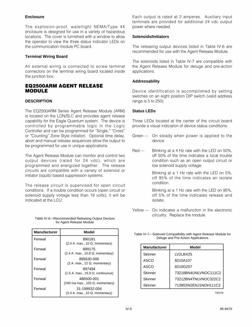
Manufacturer Model
Skinner LV2LBX25
ASCO 8210A107
ASCO 8210G207
Skinner 73218BN4UNLVNOC111C2
Skinner 73212BN4TNLVNOC322C2
Skinner 71395SN2ENJ1NOH111C2
T0037B
Table III-2—Solenoid Compatibility with Release Module for Delugeand Pre-Action Applications
Table III–1—Solenoid Compatibility with Release Module forReleasing Applications
Solenoids
Fenwal part no. 486500-001Fenwal part no. 890181Fenwal part no. 897494Fenwal part no. 899175Fenwal part no. 895630-000Fenwal part no. 31-199932-004
SIGNAL AUDIBLE MODULE
FEATURES
• Four independently programmable indicating circuits
• NFPA Style “Y” or “Z” wiring
• 24 vdc power limited outputs
• Self-restoring output design
• Four optional coded outputs per circuit.
DESCRIPTION
The signal audible module provides four indicatingcircuits for controlling UL Listed 24 vdc polarizedaudible/visual indicating appliances. Each outputcircuit is independently programmable to allowannunciation of separate events.
The outputs are UL Listed for power l imitedapplications. The advanced circuitry design usesresettable fuses, eliminating the need to replacemodules or components if the circuits are shorted oroverloaded. As a result, downtime and maintenancecosts are reduced.
The signal audible module can support four NFPA Style“Y” or two Style “Z” field wiring circuits. Each outputcircuit is supervised for open and short circuitconditions. The outputs operate in the reverse polarityfashion when activated. Each output delivers up to 2amperes at 24 vdc — enough to meet the powerrequirements of today’s ADA/UL 1971 signalingappliances.
The Signal Audible Module is located in the LIOU and issupervised by the LCU. In the event of module removal,the system displays a trouble condition at the LCU.
The Eagle Quantum system supports up to eight signalaudible modules, providing a maximum of 32 signaloutputs per system. Each module provides auxiliaryinput terminals for additional 24 vdc signaling powerwhere required. All four module outputs aresynchronized for accurate activation of visual signalingappliances.
The signal outputs are programmable for activation bythe Eagle Quantum’s Logic Controller. Time delay andstepped signaling functions can also beaccommodated. In release applications, signal outputscan be programmed to provide pre-release, releaseand post-release signaling.
Each circuit is individually programmable for any one ofthe following coded outputs:
1. Continuous sounding
2. 60 Beats per minute
3. 120 Beats per minute
4. Temporal pattern.
The signal audible module is housed and secured in theLIOU. A maximum of eight signal audible modules canbe installed in the system.
III-3 95-8470
IV-1 95-8470
Section IVAddressable Field Devices
EQ2200IDC SERIESINITIATING DEVICE CIRCUIT (IDC)
DESCRIPTION
Three IDC models are available:
The EQ2200IDC allows discrete inputs from smoke/heatdetectors, manual call stations or other contact devices.
The EQ2200IDCGF Initiating Device Circuit GroundFault Monitor responds to the presence of a ground faultwithin the power circuitry of the Eagle Quantum system.It provides a supervised dry contact input and groundfault monitoring circuitry for indicating a power supplytrouble condition. It is intended for use with a third partypower supply.
The EQ2200IDCSC Initiating Device Circuit Short Circuit(IDCSC) provides two supervised digital inputs formonitoring the system for shorts circuits. The IDCSCsupports ANSI/NFPA 72 Class B Style C (3 state,open/short circuit) supervised input circuits.
Inputs
Each IDC accepts two dry contact inputs for use withdevices such as relays, pushbuttons, key switches, etc.The IDC supports ANSI/NFPA 72 Class B Style Bsupervised input circuits (Class B Style C for IDCSC).
Each circuit requires its own end of line (EOL) resistorfor monitoring circuit continuity. Nominal resistance ofthe resistor is 10 k ohms.
Inputs are software selectable in EagleVision NT toactuate the alarm, trouble, or supervisory relays on theLCU.
Outputs
The output of the device is a status message that is sentto the gateway and logic controller in the Local ControlUnit along the LON/SLC. System response to themessage is determined at the time of configuration. TheIDC supports ANSI/NFPA 72 Class A, Style 7communication with the LCU.
A Standard Periodic Report (SPR) is sent to the gatewayat the rate determined at the time of configuration.When programmed for response to a f ire alarmcondition, a special Acknowledged Exception Report(AER) is immediately sent to the Logic Controller.
Addressability
Device identification is accomplished by settingswitches on an eight position DIP switch (valid addressrange is 5 to 250).
Status LEDs
Three LEDs are located at the center of thecommunication module circuit board and are visiblewhen the cover is removed.
The green LED serves as a power-on indicator and isthe only LED illuminated during normal operation (nofaults or alarms occurring).
The red LED is used to indicate an alarm or faultcondition. The flashing rate of the red LED indicates thefollowing conditions:
On steady = one of the inputs is activeBlinking = fault condition such as an open input
circuit or not configured.
The amber LED is provided for factory diagnosticpurposes and is not used by the customer. Illuminationof the amber LED normally indicates a failure in thecommunication chip. Replacement of the communicationmodule circuit board is required.
Alarm Log
The module tracks when either of its input circuits areactivated and will store these changes in non-volatilememory. The time, date, and circuit number is storedfor the last eight events.
Enclosure
The explosion-proof, water-t ight NEMA/Type 4Xenclosure is designed for use in a variety of hazardouslocations.
EQ2200UV UV FLAME DETECTOR
DESCRIPTION
The EQ2200UV Series UV Flame Detector contains a UVsensor module and control circuitry in an explosion-proof, watertight enclosure. The detector is equippedwith both automatic and manual optical integrity (oi) testcapability.
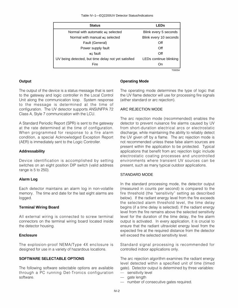
Detector status is indicated by red LEDs visible throughthe detector’s viewing window. Table IV-1 indicates thecondition of the LEDs for each detector status.
IV-2
Output
The output of the device is a status message that is sentto the gateway and logic controller in the Local ControlUnit along the communication loop. System responseto the message is determined at the t ime ofconfiguration. The UV detector supports ANSI/NFPA 72Class A, Style 7 communication with the LCU.
A Standard Periodic Report (SPR) is sent to the gatewayat the rate determined at the time of configuration.When programmed for response to a f ire alarmcondition, a special Acknowledged Exception Report(AER) is immediately sent to the Logic Controller.
Addressability
Device identification is accomplished by settingswitches on an eight position DIP switch (valid addressrange is 5 to 250).
Alarm Log
Each detector maintains an alarm log in non-volatilememory. The time and date for the last eight alarms arelogged.
Terminal Wiring Board
All external wiring is connected to screw terminalconnectors on the terminal wiring board located insidethe detector housing.
Enclosure
The explosion-proof NEMA/Type 4X enclosure isdesigned for use in a variety of hazardous locations.
SOFTWARE SELECTABLE OPTIONS
The following software selectable options are availablethrough a PC running Det-Tronics configurationsoftware.
Operating Mode
The operating mode determines the type of logic thatthe UV flame detector will use for processing fire signals(either standard or arc rejection).
ARC REJECTION MODE
The arc rejection mode (recommended) enables thedetector to prevent nuisance fire alarms caused by UVfrom short-duration electrical arcs or electrostaticdischarge, while maintaining the ability to reliably detectthe UV given off by a flame. The arc rejection mode isnot recommended unless these false alarm sources arepresent within the application to be protected. Typicalapplications that benefit from arc rejection logic includeelectrostatic coating processes and uncontrolledenvironments where transient UV sources can bepresent, such as many typical outdoor applications.
STANDARD MODE
In the standard processing mode, the detector output(measured in counts per second) is compared to thefire threshold (the “sensitivity” setting as describedbelow). If the radiant energy level from the fire exceedsthe selected alarm threshold level, the time delaybegins (if a time delay is selected). If the radiant energylevel from the fire remains above the selected sensitivitylevel for the duration of the time delay, the fire alarmoutput is activated. In every application, it is crucial toensure that the radiant ultraviolet energy level from theexpected fire at the required distance from the detectorwill exceed the selected sensitivity level.
Standard signal processing is recommended forcontrolled indoor applications only.
The arc rejection algorithm examines the radiant energylevel detected within a specified unit of time (timedgate). Detector output is determined by three variables:— sensitivity level— gate length — number of consecutive gates required.
T0005A
Status LEDs
Normal with automatic oi selected Blink every 5 seconds
Normal with manual oi selected Blink every 10 seconds
Fault (General) Off
Power supply fault Off
oi fault Off
UV being detected, but time delay not yet satisfied LEDs continue blinking
Fire On
Table IV–1—EQ2200UV Detector Status/Indications
IV-3 95-8470
Different combinations of these variables allow forvarious levels of transient arc rejection capability. Thereare four arc rejection levels (very high, high, medium,and low) that are selectable for each detector throughthe PC. Refer to Table IV-2.
The proper arc rejection setting for a given applicationmust be determined through testing. For indoorapplications with known electrostatic energy fieldswithin 15 feet of the detector, an arc rejection setting of“very high” or “high” is typical. For outdoorapplications, “medium” or “low” arc rejection settingsare typical.
It is recommended that each detector be thoroughlytested at the programmed arc rejection setting withinthe ambient conditions that will be present duringnormal operation. This will help to ensure that theselected arc rejection setting is proper for theapplication.
Sensitivity
Whether the Standard or Arc Rejection mode isselected, the sensit ivity sett ing must always beprogrammed. The selected sensitivity level determinesthe fire alarm threshold setpoint. The higher thesensitivity level, the greater the detection range, but thepossibility of false alarms will be increased. Foursensitivity levels are selectable. Refer to Table IV-3.
The sensitivity setting must be appropriate for theanticipated fire size at the required distance from thedetector.
Time Delay
Arc rejection mode — If the fire signal meets theprogrammed arc rejection requirements, the time delaybegins. A fire output is generated if the fire signalcontinues for the duration of the time delay.
Standard mode — A fire output is generated only if thefire signal exceeds the sensitivity setting for the entireduration of the programmed time delay.
Automatic or Manual oi
The oi system uses an internally generated UV testsignal to determine the relative condition of the detectorand its optical surfaces.
If automatic oi testing is selected, the oi test isautomatically performed once every minute. Theautomatic oi test does not generate an alarm output orinterfere with normal detector operation.
The manual oi test is initiated using a button on thepoint display screen at the PC. The manual oi test canbe used in addition to automatic oi to verify correctsystem operation.
Fire Output Latching
When latching operation is selected, the fire alarmsignal is cleared by removing input power for aminimum of 0.1 second.
Arc Rejection Level Consecutive Gates Gate Length Sensitivity* Min. Processing Time
Very High 8 1/16 Second Very High (8 CPS) 0.5 Second
High 4 1/16 Second Very High (8 CPS) 0.25 Second
Medium 4 1/8 Second Very High (8 CPS) 0.5 Second
Low 4 1/4 Second Very High (8 CPS) 1.0 Second
T0006A* CPS = counts per second
Table IV–2—Arc Rejection Levels for UV Detector
Sensitivity Level Equivalents
Sensitivity Level Selected Nominal Fire Alarm ThresholdIn Counts per Second (CPS)
Very High 8
High 24
Medium 48
Low 96
T0007A
Table IV–3—Sensitivity Levels for UV Detector
Fault Latching
If the fault output is set for latching, the fault will notclear until it is corrected and the unit is reset. If a fireoccurs, the unit will indicate a fire, over-riding the faultcondition, i.e., the fault signal will clear if not latched. Ifa fault is sti l l present after the f ire has beenextinguished, the unit will again indicate a fault until theproblem has been corrected and the unit is reset.
EQ2200UVHT HIGH TEMPERATUREUV FLAME DETECTOR
DESCRIPTION
The EQ2200UVHT UV Flame Detector provides UVflame protection in continuous duty high temperatureapplications, such as turbine compartments,enclosures, generator rooms, etc. where ambienttemperatures can continuously exceed +75°C (+167°F).
The EQ2200UVHT is an electronic module assemblythat is used in conjunction with a high temperature ratedC7050B UV detector (with DE1888K3 high temperaturerated UV sensor tube). The two devices are mounted inseparate explosion-proof, watertight enclosures.
The UV detector is rated for continuous duty inenvironments up to +125°C (+257°F). The electronicmodule is rated up to +75°C (+167°F).
NOTEThe electronic module cannot be located in thehigh temperature area.
The UV detector and electronic module assembly canbe separated up to 165 feet (50 meters) using hightemperature rated 4 core shielded cable.
NOTEIn accordance with NFPA 72, the maximumseparation distance is 20 feet (6 meters) usingconduit or equivalent protection againstmechanical damage.
LED
Detector status is indicated by a red LED that is visiblethrough the viewing window on the cover of theelectronic module junction box.
Refer to the “EQ2200UV UV Flame Detector” sectionabove for a description of features, operatingcharacteristics and software selectable options of Det-Tronics Eagle Quantum UV detectors.
EQ2200UVIR FLAME DETECTOR
DESCRIPTION
The EQ2200UVIR Series Flame Detector is designed toprovide reliable fire protection in applications where theuse of either ultraviolet (UV) or infrared (IR) detectorsalone can result in false alarms. When used alone, a UVdetector can respond to sources of ultraviolet radiationbesides fire, such as lightning, x-rays or arc welding.Likewise, an IR detector can respond to various hotobjects, such as flickering or chopped radiation fromelectric heaters or exhaust manifolds. Themicroprocessor based EQ2200UVIR combines both aUV and a single frequency IR sensor in a singledetector and requires simultaneous response of bothsensors to generate a fire alarm. These two detectingelements monitor different portions of the radiationspectrum and have virtually no common sources offalse alarms. This enables the detector to respond to areal fire while ignoring potential false alarm sourcessuch as arc welding, x-rays, or hot vibrating objects.
Microprocessor based circuitry located inside thedetector junction box continuously monitors the twosensors, evaluating the signal(s) with fire and faultalgorithms to determine the current status of thedetector. When both sensors simultaneously detect thepresence of fire, the microprocessor generates a firesignal, which is immediately sent over the LON/SLC tothe logic controller in the Local Control Unit (LCU). TheLEDs, visible through the UV sensor viewing window,are also immediately i l luminated. In addition, awatchdog timer assures that the detector’s operatingprogram is running properly.
Detector Output
The output of the device is a status message that is sentto the gateway and logic controller in the LCU along thecommunication loop. System response to the messageis determined at the time of configuration. The detectorsupports ANSI/NFPA 72 Class A, Style 7 communicationwith the LCU.
Status Conditions
Detector status conditions include normal operation,fire, fault, UV only, and IR only. A fire alarm signal isgenerated when both UV and IR sensors are active.The fire alarm status has the highest priority and willoverride a fault condition.
IV-4
Addressability
Device identification is accomplished by setting rockerswitches on an eight position DIP switch (valid addressrange is 5 to 250).
Alarm Log
Each detector maintains an alarm log in non-volatilememory. The time and date for the last 8 alarms arelogged.
Enclosure
The explosion-proof NEMA/Type 4X enclosure isavailable in either aluminum or stainless steel and isdesigned for use in a variety of hazardous locations.
LEDs
Detector status is indicated by a pair of red LEDs(illuminated simultaneously) that are visible through theviewing window of the UV sensor.
Table IV-4 indicates the condition of the LEDs for eachdetector status.
Automatic Diagnostics
The microprocessor based detector is equipped withadvanced fault detection and diagnostic capabilities.The LED indicators on the UV sensor module providethe user with visual annunciation of the problem area.In addition, the point display screen at the OIS providesa variety of information regarding detector status as wellas the actual UV and IR signal levels present at thedetector. Refer to Table IV-5 for a list of statusconditions.
SOFTWARE SELECTABLE OPTIONS
The following options are selectable through a PCrunning Det-Tronics configuration software:
Processing Mode
The UV portion of the detector offers a choice of twodifferent types of logic that can be used for processingfire signals — either standard or arc rejection.
ARC REJECTION MODE
The arc rejection mode (recommended) enables thedetector to prevent nuisance fire alarms caused byshort-duration electrical arcs or electrostatic discharge,while maintaining the ability to reliably detect a flame.The arc rejection mode is not recommended unlessthese false alarm sources are present within theapplication to be protected. Typical applications thatbenefit from arc rejection logic include any uncontrolledenvironments where transient radiation sources can bepresent, such as many typical outdoor applications.
The arc rejection algorithm examines the radiant energylevel detected within a specified unit of time (timedgate). The output of the detector is determined by threevariables:— sensitivity level— gate length — number of consecutive gates required.
Different combinations of these variables allow forvarious levels of transient arc rejection capability. Thereare two arc rejection levels (medium and high) that areselectable for the detector through the OIS. The properarc rejection setting for a given application must bedetermined through testing.
IV-5 95-8470
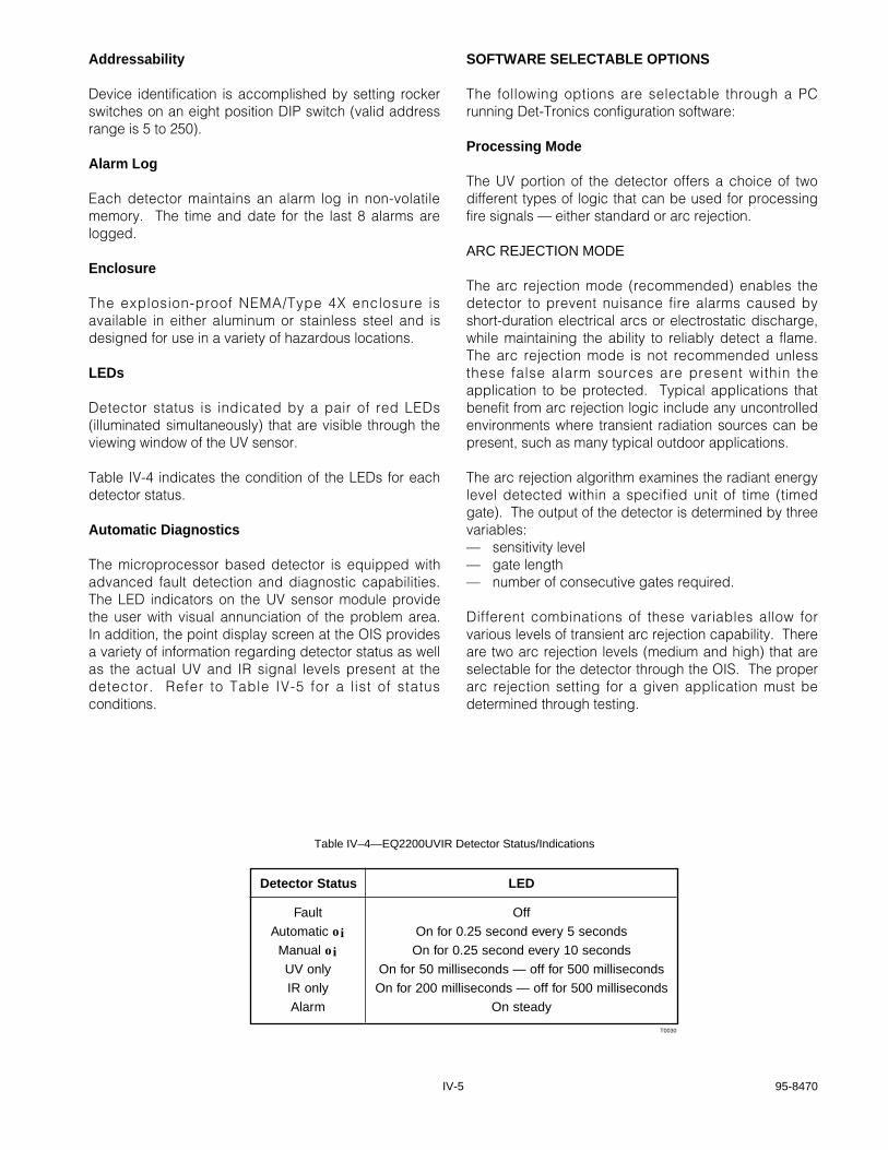
Detector Status LED
Fault OffAutomatic oi On for 0.25 second every 5 seconds
Manual oi On for 0.25 second every 10 secondsUV only On for 50 milliseconds — off for 500 millisecondsIR only On for 200 milliseconds — off for 500 millisecondsAlarm On steady
T0030
Table IV–4—EQ2200UVIR Detector Status/Indications
IV-6
Status Indication Possible Cause
Low Voltage Power supply.Detector power wiring.
COM 1 LON wiring on COM 1 side of detector.Detector communication circuitry problem.
COM 2 LON wiring on COM 2 side of detector.Detector communication circuitry problem.
IR Alarm IR radiation source within view of detector.
UV Alarm UV radiation source within view of detector.
Not communicating Power supply or power wiring problem.LON wiring problem.Detector communication circuitry problem.Wrong DIP switch address setting.
Inhibit active Inhibit activated at OIS.
Unable to configure Configuration problem. Repeat configuration.
UV fault Defect in UV module. (See extended status.)
IR fault Defect in IR module. (See extended status.)
Power-up Detector in power-up time delay. Solution: Wait for detector to exit delay. Replace detector.
Auto configuration fault Configuration problem. Repeat configuration.
General fault Power supply failure.Power or LON wiring problem.Electronic failure in detector.
Fire alarm UV and IR radiation detected.
UV oi fault UV viewing window or oi ring dirty.UV oi ring missing.
UV tube missing Module missing. Install module.Dirty or broken contacts on module.
UV 290 volt fault Internal power problem. Replace detector terminal board.
IR oi fault IR viewing window or oi ring dirty.IR oi ring missing.
IR missing module Module missing. Install module.Dirty or broken contacts on module.
T0031B
Table IV–5—Status Conditions of UV/IR Detector
It is recommended that each detector be thoroughlytested at the programmed arc rejection setting withinthe ambient conditions that will be present duringnormal operation. This will help to ensure that theselected arc rejection setting is proper for theapplication.
STANDARD MODE
In the standard processing mode, the UV sensor output(measured in counts per second) is compared to thefire threshold (the “sensitivity” setting as describedbelow). If the radiant energy level from the fire exceedsthe selected alarm threshold level, the time delaybegins (if a time delay is selected). If the radiant energylevel from the fire remains above the selected sensitivitylevel for the duration of the time delay, a fire alarmsignal is generated. In every application, it is crucial toensure that the radiant energy level from the expectedfire at the required distance from the detector willexceed the selected sensitivity level.
Standard signal processing is recommended forcontrolled indoor applications only.
Sensitivity
Whether Arc Rejection or Standard mode is selected,the sensitivity setting must always be programmed. Theselected sensitivity level determines the fire alarmthreshold setpoint. The higher the sensitivity level, thegreater the detection range, but the possibility of falsealarms will be increased. Four sensitivity levels areselectable. (Sensitivity levels for UV and IR are selectedseparately.)
The sensitivity setting must be appropriate for theanticipated fire size at the required distance from thedetector. Refer to the “Specifications” section of thismanual for additional information.
Time Delay
A time delay from 0 to 7 seconds is selectable.
STANDARD MODE
A fire output is generated only if the fire signal exceedsthe sensitivity setting for the entire duration of theprogrammed time delay.
ARC REJECTION MODE
If the fire signal meets the programmed arc rejectionrequirements, the time delay begins. A fire output isgenerated if the fire signal continues for the duration ofthe time delay.
Automatic or Manual oi
The EQ2200UVIR is equipped with the Optical Integrity(oi) feature. The oi test is performed on both the UVand IR sensors to check the cleanliness of the detectoroptics, as well as the proper functioning of the sensorsand electronic components of the detector. If aproblem should occur, it is quickly detected.
The detector is user programmable (from a PC runningDet-Tronics configuration software) for automatic oitesting. If automatic testing is selected, the oi test isautomatically performed on each sensor. The rate forthe UV sensor test is once per minute. The rate for theIR sensor is field selectable from once a minute to onceevery four hours. If a fault is detected, a trouble signalis sent to the LCU over the LON/SLC. A fault conditionis indicated at the logic controller and the gateway andalso by the LEDs on the detector’s UV sensor. Theautomatic oi test does not generate an alarm output orinterfere with normal detector operation.
The manual oi test is initiated using a button on thepoint display screen at the OIS. A successful test issignaled by the OIS. The manual oi test can be used inaddition to automatic oi to verify correct detectoroperation.
NOTEThe manual oi test does not generate an alarmoutput or actuate any system outputs.
Fire Output Latching
When latching operation is selected, the fire alarmsignal is present until cleared by a reset command fromthe PC.
EQ2200DCU AND EQ2200DCUEXDIGITAL COMMUNICATION UNIT
DESCRIPTION
The EQ2200 Series Digital Communication Unit (DCU)digitizes a 4 to 20 ma analog signal and transmits thevalue as the process variable portion of its StandardPeriodic Report (SPR) to the Communication Gatewaylocated in the LCU. All circuitry is housed in a singleexplosion-proof/watertight enclosure for use in the areaof detection.
Designed for use with the Eagle Quantum system, theDCU provides a unique technique for detecting andisolating opens or shorts in the Local OperatingNetwork/Signaling Line Circuit (LON/SLC) wiring. This
IV-7 95-8470
fault isolation method allows for communication integrityin the event of a single wiring fault in the LON/SLCwiring.
The DCU is approved for use with a variety of DetectorElectronics sensors including catalytic combustible gassensors, the PointWatch IR gas detector, as well aselectrochemical sensors (hydrogen sulfide, carbonmonoxide, chlorine, sulfur dioxide, and nitrogendioxide). It will also accept any sensor with a linear 4 to20 ma output signal and allows for one person non-intrusive calibration.
Inputs
The DCU features one 4 to 20 ma non-isolated input,with an input impedance of 200 ohms in series with aprotection diode. (When used with a Det-Tronicscatalytic combustible gas sensor, a separate transmitterboard converts the millivolt output to a 4 to 20 masignal.) The DCU also monitors its 24 vdc supplyvoltage and reports to the PC when requested.
Output
The Standard Periodic Report (SPR) is sent to thegateway at the rate determined at the t ime ofconfiguration (from one to ten seconds).
Calibration
A magnetic reed switch, located on the terminal board,enables calibration of the sensor without opening theenclosure. The switch is activated by placing acalibration magnet at a specified location on the side ofthe enclosure. Once the calibration mode has beenentered, the DCU steps the user through the process.For details, refer to the “Calibration” section of thismanual.
Addressability
Device identification is accomplished by settingswitches on an eight position DIP switch (valid addressrange is 5 to 250).
Status LEDs
Three LEDs are located at the center of thecommunication module circuit board and are visiblethrough the window on the enclosure cover.
The green LED serves as a power-on indicator and isilluminated whenever power is applied. During normaloperation, only the green LED is illuminated.
The red LED is used to indicate a calibration, power-up,fault or alarm condition. The flashing rate of the redLED indicates the following conditions:
Power-up = Pulsed at a 0.5 Hz rateCalibration = Pulsed at a 1 Hz rate or on steadyFault = Pulsed at a 4 Hz rateAlarm = Illuminated continuously.
NOTEIf the communication module has not beenconfigured, the red LED blinks at the 4 Hz rate.
The amber LED is provided for factory diagnosticpurposes and is not used in the system. Illumination ofthe amber LED normally indicates a failure in thecommunication chip. Replacement of thecommunication module circuit board is required.
Calibration Log
The DCU keeps a calibration log in non-volatile memorythat can be used by the operator to evaluate theremaining life of some sensors. This log includes thezero, span, date and time for each successfulcalibration. An aborted calibration is indicated by zerosin the zero and span values. The calibration log iscleared when the sensor replacement switch is pressedand the calibration is successfully completed.
The initial calibration is logged in position one, where itremains for the life of the sensor. If more than 8calibrations are performed without the sensorreplacement switch being pressed, the newestcalibration data will replace the second oldest so thatthe initial calibration data can be saved. The oldcalibration data will be lost. This feature enables sensorsensit ivity trending to aid in maintenance ortroubleshooting.
The analog value for the sensor is represented in rawanalog to digital counts 0 to 4095, where 0 represents 0ma and 4095 represents 24 ma.
Alarm Log
A log of low and high alarms is stored in each DCU.Time, date and alarm type are logged for each alarmevent. A maximum of eight events can be stored. Ifmore than eight events are logged, the oldest event willbe overwritten.
IV-8
Enclosure
The explosion-proof, watertight NEMA/Type 4Xenclosure is designed for use in a variety of hazardouslocations. The cover is furnished with a window to allowthe operator to view the three status indicator LEDs onthe communication module PC board.
Terminal Wiring Board
All external wiring is connected to screw terminalconnectors on the terminal wiring board located insidethe junction box.
EQ2500ARM AGENT RELEASEMODULE
DESCRIPTION
The EQ2500ARM Series Agent Release Module (ARM)is located on the LON/SLC and provides agent releasecapability for the Eagle Quantum system. The device iscontrolled by programmable logic in the LogicController and can be programmed for “Single,” “Cross”or “Counting” Zone Style initiation. Optional time delay,abort and manual release sequences allow the output tobe programmed for use in unique applications.
The Agent Release Module can monitor and control twooutput devices (rated for 24 vdc), which areprogrammed and energized together. The releasecircuits are compatible with a variety of solenoid orinitiator (squib) based suppression systems.
The release circuit is supervised for open circuitconditions. If a trouble condition occurs (open circuit orsolenoid supply voltage less than 19 volts), it will beindicated at the LCU.
Each output is rated at 2 amperes. Auxiliary inputterminals are provided for additional 24 vdc outputpower where needed.
Solenoids/Initiators
The releasing output devices listed in Table IV-6 arerecommended for use with the Agent Release Module.
The solenoids listed in Table IV-7 are compatible withthe Agent Release Module for deluge and pre-actionapplications.
Addressability
Device identification is accomplished by settingswitches on an eight position DIP switch (valid addressrange is 5 to 250).
Status LEDs
Three LEDs located at the center of the circuit boardprovide a visual indication of device status conditions.
Green — On steady when power is applied to thedevice.
Red — Blinking at a 4 Hz rate with the LED on 50%,off 50% of the time indicates a local troublecondition such as an open output circuit orlow solenoid supply voltage.
Blinking at a 1 Hz rate with the LED on 5%,off 95% of the time indicates an isolatecondition.
Blinking at a 1 Hz rate with the LED on 95%,off 5% of the time indicates release andisolate.
Yellow — On indicates a malfunction in the electroniccircuitry. Replace the module.
IV-9 95-8470
Manufacturer Model
Skinner LV2LBX25
ASCO 8210A107
ASCO 8210G207
Skinner 73218BN4UNLVNOC111C2
Skinner 73212BN4TNLVNOC322C2
Skinner 71395SN2ENJ1NOH111C2
T0037B
Table IV-7—Solenoid Compatibility with Agent Release Module forDeluge and Pre-Action Applications
Manufacturer Model
Fenwal 890181(2.4 A. max., 10 Ω, momentary)
Fenwal 899175(2.4 A. max., 10.8 Ω, momentary)
Fenwal 895630-000(2 A. max., 12 Ω, momentary)
Fenwal 897494(1.5 A. max., 15.9 Ω, continuous)
Fenwal 486500-001(240 ma max., 103 Ω, momentary)
Fenwal 31-199932-004(2.4 A. max., 10 Ω, momentary)
Time and date are logged each time that a releaseoccurs. Data for the last eight events is stored in non-volatile memory.
Terminal Wiring Board
All external wiring is connected to screw terminalconnectors on the terminal wiring board located insidethe device enclosure.
EQ2500SAM SIGNAL AUDIBLEMODULE
DESCRIPTION
The EQ2500SAM Series Signal Audible Module (SAM)provides two indicating circuits for controlling UL Listed24 vdc polarized audible/visual indicating appliances.The device is located on the LON/SLC and is controlledby programmable logic in the Eagle Quantum’s LogicController.
Each output circuit is independently programmable toallow annunciation of separate events. In releaseapplications, signal outputs can be programmed toprovide signaling for pre-release, release or post-release. Each output can be individually activated forany one of the following pre-defined coded outputs:
1. Continuous until reset
2. 60 beats per minute
3. 120 beats per minute
4. Temporal pattern.
The outputs operate in the reverse polarity fashion whenactivated. Each output is rated at 2 amperes. Auxiliaryinput terminals are provided for additional 24 vdcsignaling power where required.
The output circuits are supervised for open and shortcircuit conditions. If a wiring fault occurs, a troublecondition will be indicated at the LCU.
Addressability
Device identification is accomplished by settingswitches on an eight position DIP switch (valid addressrange is 5 to 250).
Status LEDs
Three LEDs located at the center of the circuit boardprovide a visual indication of device status conditions.
Green — On when power is applied to the device.
Red — On steady indicates an active condition.
Blinking indicates a local trouble conditionsuch as an open or shorted output circuit orlow output supply voltage.
Yellow — On indicates a malfunction in the electroniccircuitry. Replace the module.
Alarm Log
Time and date are logged each time that a fire alarmoccurs. Data for the last eight events is stored in non-volatile memory.
Terminal Wiring Board
All external wiring is connected to screw terminalconnectors on the terminal wiring board located insidethe device enclosure.
EQ2400NE NETWORK EXTENDER
DESCRIPTION
The EQ2400NE Series Network Extender expands thecapabilities of the Eagle Quantum system by allowingadditional nodes as well as additional wiring to beadded to the LON/SLC (communication loop). Without anetwork extender, the communication network is limitedto 60 nodes on a 2000 meter loop. Each networkextender, however, increases the capacity of the loopby up to 40 nodes and 2000 meters of wiring, up to amaximum of 244 field nodes and 10,000 meters ofwiring.
Network extender circuitry supports communication inboth directions. If a network wiring fault should occur,uninterrupted communication can continue in theopposite direction.
LEDs
The network extender’s electronic module is furnishedwith three LEDs (one green and two yellow) forindicating device status.
IV-10
The green LED indicates that power is applied andflashes to indicate that messages are being transferredover the network.
The two yellow LEDs correspond to the twocommunication transceivers and are illuminated toindicate that an internal fault has been detected.
Enclosure
The network extender’s electronic circuitry is mountedinside an explosion-proof, water-tight enclosure forinstallation in hazardous locations. The enclosure isavailable with up to six 3/4 inch NPT or 25 mm conduitentries.
GENERAL APPLICATION INFORMATION
System Capacity
The basic Eagle Quantum system supports acommunication loop consisting of up to 60 detectionnodes and up to 2000 meters of connecting wiring.Adding a network extender to the loop allows it to beexpanded by up to 40 nodes with an additional 2000meters of wiring. Up to 6 network extenders can beutilized in a single system, supporting up to 244 fieldnodes and up to 10,000 meters of wiring.
To ensure optimum performance, it is important todistribute the network extenders along the loop so thatthere are no more than 40 detection nodes or 2000meters of wiring on either side of a network extender.See Figure IV-1.
Response Time vs. System Size
When designing a system, it is important to realize thatincreasing the number of nodes on the communicationloop can result in an increase in the amount of timerequired for a status change message from a detectionnode to reach the host computer.
The gateway requires a finite length of time to processeach bit of information that is transferred along thecommunication network. As the number of nodesincreases, so does the amount of data that is beingprocessed as well as the time required for processingthe data. As a result, the update time for each nodeshould be increased to accommodate the extra trafficfor a large system (one second minimum for each 50nodes).
If the fastest possible communication response time isan important criteria for a large system, it isrecommended that the number of nodes on anindividual loop be kept as small as practical. Considerusing multiple loops with fewer nodes per loop ratherthan one large loop.
IV-11 95-8470
LCU
60 NODE LOOP
RIGHT
RIGHT
LCU
100 NODE LOOP
NE
50 NODES 50 NODESWRONG
LCU
100 NODE LOOP
NE NE40 NODES
30 NODES30 NODES
NOTES: 1. BASIC LOOP WITHOUT A NETWORK EXTENDER CANNOT EXCEED 60 NODES AND 2000 METERS OF WIRE.
2. NO MORE THAN 40 NODES AND 2000 METERS OF WIRE BETWEEN NETWORK EXTENDERS OR BETWEEN A NETWORK EXTENDER AND THE LCU.
3. NO MORE THAN 244 FIELD NODES AND 10,000 METERS OF WIRE ON THE LOOP.
A1946
Figure IV-1—Eagle Quantum Communication Loops
V-1 95-8470
Section VDetector Application
Information
UV DETECTORS
In applying any type of sensing device as a firedetector, it is important to know of any conditions thatcan prevent the device from responding to a fire, andalso to know what other sources besides fire will causethe device to respond.
WINDOWS
Glass and plexiglas windows significantly attenuate UVradiation and must not be located between the detectorand a potential flame source. If the window cannot beeliminated or the detector location changed, contactDetector Electronics for recommendations regardingwindow materials that will not attenuate UV radiation.
OBSTRUCTIONS
For an ultraviolet detector, dust, dirt and other films, UVabsorbing gases or vapors as well as physicalobstructions must not be allowed to come between thedetector and the protected hazard (see Table V-1).
SMOKE
Smoke will absorb UV radiation, and if accumulations ofdense smoke can be expected to precede thepresence of flame, then ultraviolet detectors that areused in enclosed areas should be mounted on the wallapproximately 3 feet (1 meter) from the ceiling wherethe accumulation of smoke is reduced.
ARC WELDING
Electric arc welding is a source of intense ultravioletradiation, and care must be taken to ensure that arcwelding is not performed in the protected area withoutsecuring the fire detection system. UV radiation fromarc welding readily scatters and can deflect acrosssignificant distances, even when direct obstructionsexist. Any open door or window can allow nuisance UVradiation from arc welding to enter an enclosed area.
When x-rays or radioactive substances are present inthe area being protected, the UV system must bedisabled until those sources are removed.
COMMON ENVIRONMENTAL CONDITIONS
The detector is not affected by environmental conditionssuch as wind, rain or extremes of temperature and
pressure. It is also insensitive to the ultravioletcomponent of solar radiation.
UV radiation generated by periodic lightning or sparksin the area can be effectively ignored by the detectorusing the arc rejection feature or time delay.
UV detectors should not be positioned so that their coneof vision can scan the horizon. Rather, they should bedirected down over the designated hazardous area toreduce the likelihood of picking up UV radiation fromdistant sources.
The following is a partial list of compounds that exhibitsignificant UV absorption characteristics. These are alsousually hazardous vapors. While generally of littleconsequence in small amounts, these gases can restrictUV detection if they are in the atmosphere in heavyconcentrations. It should also be determined whether ornot large amounts of these gases may be released as aresult of a fire-causing occurrence.
If UV-absorbing gases may be a factor in a givenapplication, precautionary measures should be taken.Detectors can be placed closer to the potential hazardarea, and/or the sensitivity of the detection system can beincreased. Contact the factory for further details.
Substances such as methane, propane, butane, hexane,camphor and octane are not UV absorbing.
Absorption of infrared radiation in the range of 4.2 to 4.7microns is not a significant problem with most organicvapors, with the exception of those compounds that havetriple bonds such as acetylene, nitriles, silane, orisocyanates. Carbon dioxide concentrations higher thannormally present in the atmosphere can also causesubstantial loss of fire detection sensitivity.
Table V-1—UV and IR Absorbing Gases and Vapors
V-2
UV DETECTOR POSITIONING
Detectors should be positioned to provide the bestunobstructed view of the area to be protected. Thefollowing factors should be taken into consideration:
• Identify all high risk fire ignition sources.
• Be sure that enough detectors are used to adequatelycover the hazardous area.
• For fastest response time, locate the detector as closeas possible to the anticipated fire source. The centralaxis of the detector’s cone of vision provides thehighest sensitivity.
• Be sure that the unit is easily accessible for cleaningand other periodic servicing.
• Particular attention should be paid to potential falsealarm sources within the cone of vision of the detector.
• For outdoor applications, the detector should beaimed downward at least 10 to 20 degrees to preventit from scanning the horizon. This minimizes responseto distant UV sources outside the protected area. SeeFigure 1.
• Dense fog, rain or ice will absorb UV radiation andreduce the sensitivity of the detector.
• If smoke is expected before flame, it is recommendedthat smoke or other additional detectors be used inconjunction with the UV detector.
If possible, fire tests should be conducted to verifycorrect detector positioning and coverage.
UV/IR DETECTORS
FALSE ALARM SOURCES
UV: The UV sensor is insensitive to the ultravioletcomponent of solar radiation. However, it willrespond to sources of UV besides fire, such aselectric arc welding, lightning, high voltage corona,x-rays and gamma radiation.
IR: The detector has been designed to ignore steadystate infrared sources that do not have a flickerfrequency characteristic of a fire, however, it shouldbe noted that if these steady state infrared sourcesare hot enough to emit adequate amounts ofinfrared radiation in the response range of the IRsensor and if this radiation becomes interruptedfrom the view of the detector in a patterncharacteristic of a flickering flame, the IR sensorcan respond.
Any object having a temperature greater than 0°Kelvin (–273°C) emits infrared radiation. The hotterthe object, the greater the intensity of the emittedradiation. The closer the infrared source is to thedetector, the greater the potential for a false alarm.The IR sensor can respond to IR radiation sourcesthat can meet the amplitude and fl ickerrequirements of the detector such as vibrating hotobjects.
Although the detector is designed to reduce falseactuations, certain combinations of ambientradiation must be avoided. For example, if IRradiation with an intensity that exceeds the firethreshold of the IR sensor should reach the detectoras a flickering signal, and if at the same time anelectric arc welding signal also reaches thedetector, an alarm output will be generated.
NOTERadiation generated by false alarm sources suchas periodic lightning or sparks in the area can beeffectively ignored by the detector using the arcrejection feature or time delay.
Arc Welding
Electric arc welding is a source of intense ultravioletradiation. UV radiation from arc welding readily scattersand can deflect across significant distances, even whendirect obstructions exist. Any open door or window canallow nuisance UV radiation from arc welding to enteran enclosed area.
CENTER AXIS OF DETECTOR FIELD OF VIEW
CENTER AXIS OF DETECTOR FIELD OF VIEW
INCORRECT
CORRECT
NOTE: DETECTOR MUST ALWAYS BE AIMEDDOWNWARD AT LEAST 10 TO 20 DEGREES.
B1974
Figure 1—Detector Orientation Relative to Horizon
The UV/IR detector does not respond to arc weldingbeyond 10 feet from the detector. However, a UV onlysignal will be generated in response to the intense UVradiation generated by the arc welding, and atdistances closer than 10 feet the heated metal from thewelding can become a false alarm source for the IRsensor.
FACTORS INHIBITING DETECTOR RESPONSE
Windows
Glass and Plexiglas windows significantly attenuateradiation and must not be located between the detectorand a potential flame source. If the window cannot beeliminated or the detector location changed, contactDetector Electronics for recommendations regardingwindow materials that will not attenuate radiation.
Obstructions
Radiation must be able to reach the detector in order forit to respond. Care must be taken to keep physicalobstructions out of the line of view of the detector. Inaddition, UV or IR absorbing gases or vapors must notbe allowed to accumulate between the detector and theprotected hazard. See Table V-1 for a list of thesesubstances.
Smoke
Smoke will absorb radiation. If accumulations of densesmoke can be expected to precede the presence of aflame, then detectors that are used in enclosed areasshould be mounted on the wall approximately 3 feet (1meter) from the ceiling where the accumulation ofsmoke is reduced.
Detector Viewing Windows
It is important to keep the detector viewing windows asfree of contaminants as possible in order to maintainmaximum sensit ivity. Commonly encounteredsubstances that can significantly attenuate UV and/or IRradiation include, but are certainly not limited to, thefollowing:
SiliconesOils and greasesIce buildupDust and dirt buildupPaint overspray.
UV/IR DETECTOR POSITIONING
IMPORTANTDetectors should not be positioned so that theircone of vision can scan the horizon. Rather, theyshould be directed down over the designatedhazardous area to reduce the likelihood of pickingup radiation from distant sources. See Figure 1.
Detectors should be located in positions best suited forcovering the area to be protected. Whenever practical,they should be placed where they will be easilyaccessible for cleaning and other periodic servicing.Particular attention should also be paid to potential falsealarm sources within the cone of vision of the detector,such as distant arc welding, or the rotating blades of afan or surface vibration of an IR source, which couldallow a flickering IR signal to reach the detector. Rainor ice can absorb radiation, which can reduce thecapability of the detector. For outdoor applications, aimthe detector downward to minimize the buildup of wateror ice on the detector viewing windows and to preventthe cone of vision from scanning the horizon. Thisminimizes response to distant radiation sources outsidethe protected area.
GAS DETECTOR POSITIONING
The sensor must be properly located to enable it toprovide maximum protection. The formula fordetermining the most effective number and placementof sensors varies depending on the conditions at the jobsite. The individual performing the installation must relyon experience and common sense to determine thequantity of sensors and the best sensor locations toadequately protect the area.
The following factors should be considered for everyinstallation:
1. What kind of gas is to be detected? If it is lighterthan air (acetylene, hydrogen, methane, etc.), placethe sensor above the potential source. Place thesensor close to the floor for gases that are heavierthan air (benzene, butane, butylene, propane,hexane, pentane, etc.) or for vapors resulting fromflammable liquid spills. However, note that aircurrents can cause a gas that is heavier than air torise. In addition, if the gas is hotter than ambientair, it could also rise.
2. How rapidly will the gas diffuse into the air? Selecta location for the sensor as close as practical to theanticipated source of a gas leak.
V-3 95-8470
V-4
3. Ventilation characteristics of the immediate areamust also be considered. Movement of air willcause gas to accumulate more heavily in one areathan another. The sensor should be placed in thearea where the most concentrated accumulation ofgas is anticipated. Also consider the fact that manyventilation systems do not operate continuously.
4. The sensor should be pointed down to prevent thebuildup of moisture or contaminants on the filter andto ensure proper operation. For PointWatch, refer toinstruction manual 95-8440.
5. The sensor must be accessible for testing andcalibration. The use of the Sensor Separation Kitwill be required in some installations.
6. Catalytic sensors should be located where they aresafe from potential sources of contamination thatcan poison the sensing element.
7. Exposure to excessive heat or vibration can result inpremature failure of any electronic device andshould be avoided if possible. Shielding the devicefrom intense sunlight will reduce solar heating andcan increase the life of the unit.
For additional information on determining quantity andplacement for sensors in a specific application, refer toInstrument Society of America (ISA) Transaction Volume20, Number 2, titled “The Use of Combustible Detectorsin Protecting Facilities from Flammable Hazards.”
CATALYTIC GAS SENSORS
CAUTIONExposure to a high level of gas can have anadverse effect on the sensitivity of catalytic sensingelements. If the level of gas at the sensor shouldreach 100% LFL, it is important that it be testedand recalibrated if required. In some cases, it maybe necessary to replace the sensor.
If an over-range condition should occur, the usermust exercise caution, since a highly explosivecondition could exist. The hazardous area shouldbe checked with a portable detection instrument todetermine the actual level of combustible gaspresent.
For best calibration results, allow a new sensor tooperate for several hours to ensure a stable outputbefore performing calibration. For the highest degree ofaccuracy, perform a second calibration after 24 hours.
When a sensor is exposed to a different or newenvironment, calibration should be checked frequentlyto determine the proper interval between periodiccalibrations.
Before performing calibration, the operator shouldexamine the sensor filter (flame arrester) to be sure thatit is not missing or damaged. If the filter is defective ormissing, it must be replaced. In some cases, anexposed sensing element can act as an ignition source.It should also be noted that a dirty cover cansignificantly reduce the sensitivity of the sensor.
CATALYTIC SENSOR OPERATION
The sensing element used in the combustible gassensor consists of a pair of elements. One is an activecatalytic sensing element, and the other is inactive andacts as a temperature compensating reference element.Both elements are composed of a wire coil encased inceramic. The active element has a catalytic coatingapplied to its surface, however, the reference element isglazed so that it does not react to the presence of acombustible gas/air mixture. The pair is computermatched to have the same electrical resistance.
In the presence of a combustible gas/air mixture, theresistance of the active sensing element increases inproportion to the concentration of gas at the sensor.The change in resistance of the active sensing element,relative to that of the reference element, is used todetermine the actual level of combustible gas present atthe sensor.
Both elements operate at a high temperature and areenclosed by a porous stainless steel cup (flamearrester). See Figure V-2. This cup allows the diffusionof gas to and from the sensing element, but preventsthe ignition of the atmosphere outside the sensor shouldthe combustible gas concentration exceed its LFL.
A barrier is placed between the element pair to preventthermal interaction and to prevent the transfer ofcatalytic material from the active element to the surfaceof the reference element.
All catalytic type sensors require oxygen to detectcombustible gases. The sensor response will decreaseif enough combustible gas displaces the normal oxygenpresent in air. The sensor should not be used where theoxygen level is less than 10%. See Figure V-3.
Figure V-4 shows the response of a typical sensor tovarious levels of combustible gas. Note that a reading of40% LFL will be given at 2.0% methane (40% LFL) and
also at 80.0% methane, well above the upper flammablelimit of methane. Although gas levels above the upperflammable limit will not propagate a flame, it stands toreason that somewhere between the leak and clear airthere will be a flammable mixture.
CAUTIONIt is possible for the display to drop to a low % LFLreading after going into high alarm and still have anunsafe level of combustible gas present.Therefore, precautions should be taken to ensurethat the combustible gas has been cleared beforeclassifying the area as safe.
V-5 95-8470
ACTIVE ELEMENT REFERENCE ELEMENT
THERMAL BARRIERFLAME ARRESTER
RE
D
WH
T
BL
K
B1124
Figure V–2—Catalytic Combustible Gas Sensor
0 905 10 15 20 30 40 50 60 70 80 100
100
90
80
70
60
50
40
30
20
10
0
CONTROLLERDISPLAYREADING
(%LFL)
PERCENT OF OXYGEN IN MIXTURE (BY VOLUME)B1126
50% LFL METHANE IN STANDARD AIR
4.5% METHANE
2.5% METHANE
90% LFL METHANE IN STANDARD AIR
Figure V–3—Effect of Oxygen Enriched and Deficient Atmosphere on the Response of a Typical Catalytic Sensor
SENSITIVITY LOSS IN CATALYTIC COMBUSTIBLEGAS SENSORS
There are a variety of factors that can cause a decreasein the sensitivity of catalytic type combustible gassensors. Interfering or contaminating substances thatcan adversely affect the response of the sensor tocombustible gases are as follows:
A. Materials that can clog the pores of the sinteredmetal flame arrestor and reduce the gas diffusionrate to the sensor are:
1. Dirt and oil.
A dust cover should be installed to protect theflame arrester whenever these conditions exist.
The dust cover can be cleaned as part of routinemaintenance. This can be accomplished usingan organic solvent and an ultrasonic bath.
2. Corrosive products.
This occurs when substances such as Cl2(Chlorine) or HCl are present. A dust coverprovides some protection. The dust covershould be replaced as part of routinemaintenance.
3. Flame arrester clogged as a result of paintingor house cleaning.
The routine maintenance procedure shouldinclude covering the sensor with a plastic bagwhen painting or cleaning. The bag should beremoved as soon as possible when theprocedure is complete.
4. Polymer formation in the flame arrester.
This can occur where monomer vapors such as1-3 butadiene, styrene, isoprene, etc. arepresent.
B. Substances that cover or tie up the active sites onthe catalytic surface of the active sensing element.
This occurs in the presence of volatile metalorganics, gases, or vapors of hydrides, and volatilecompounds containing phosphorous, boron,silicone, etc.
Figure V–4—Typical Response of Catalytic Sensor to All Possible Mixtures of Methane and Air
C. Materials that remove the catalytic metals from theactive element of the sensor.
Some substances react with the catalytic metalforming a volatile compound. This erodes the metalfrom the surface. With sufficient exposure, most orall of the metal catalyst can be removed from thesurface of the active element of the sensor.
Halogens and compounds containing halogen arematerials of this nature.
Examples:Chlorine Bromine Iodine Hydrogen Chloride, Bromide or Iodide Organic halides:
A brief exposure to one of these materials cantemporarily increase the sensitivity of the sensor.This results because the surface of the activeelement is increased due to etching. Prolongedexposure continues the etching process until thesensitivity of the sensor is degraded, resulting inshortened sensor life.
D. Exposure to high concentrations of combustiblegases.
Exposure of the sensor to high concentrations ofcombustible gases for extended periods of timecan introduce stress to the sensing element andseriously affect its performance. After exposure toa high concentration of combustible gas,recalibration should be performed and, ifnecessary, the sensor should be replaced.
The degree of damage to the sensor is determinedby a combination of the type of contaminant, itsconcentration in the atmosphere, and the length oftime the sensor is exposed. When a sensor hasbeen exposed to a contaminant or a high level ofcombustible gas, it should be calibrated at the time,followed by an additional calibration a few dayslater to determine whether a significant shift insensitivity has occurred.
E. A combination of accessories such as rain shieldsand dust covers is not recommended and canresult in slow response to a gas leak.
CALIBRATION GAS
Before calibrating a sensor, check the label on thecalibration gas cylinder to ensure that the correct gastype and concentration are being used. If a differentgas type is being used for calibration, refer to Det-Tronics Technical Note No. GTN01 for “K-Factor”information (Det-Tronics form number 99-1068-02).
V-7 95-8470
Section VIGeneral Wiring Requirements
GENERAL INFORMATION
WARNINGDo not open any junction box or device enclosurewhen power is applied without first de-classifyingthe hazardous area.
CAUTIONAny deviation from the recommended wiringpractices can compromise system operation.Consult the factory if different wire types ormethods are being considered.
NOTEAll wiring must be marked per NFPA 70 Article760.
NOTESpecific installation requirements may differdepending on local installation practices andcompliance with third party certifications. For localinstallation practices, consult the local authorityhaving jurisdiction. For compliance with third partycertifications, consult the appropriate appendix inthis manual for additional specific installationrequirements.
POWER WIRING
The input voltage at the field devices must be 18 vdcminimum to ensure proper operation of the devices.Therefore, it is important to consider both the size(gauge) of the power wiring and the wiring distancefrom the power supply. As the wiring distanceincreases, larger diameter wire is required to maintain aminimum of 18 vdc at the device.
Refer to Table VI-1 to determine the minimum wire sizeneeded to prevent excessive voltage drop from powersupply to device for a given current load.
To use Table VI-1, first determine the total current loadfor the circuit and the maximum allowable voltage drop.Then look under the appropriate Amp Load column todetermine the minimum wire size that will not allow thevoltage drop to exceed the maximum allowable.
For example:
What wire size is required to power ten DCUs at adistance of 100 feet from the power supply, assuming a24 VDC power supply and a minimum of 18 VDCneeded to power the DCUs?
Maximum allowable voltage drop is 6 VDC.(24 – 18 = 6)
Table VI-1—Voltage Drop Per Pair in Volts DC per 100 Feet from Power Supply to Device
NOTES: This table is for reference only and does not replace good engineering practice.Use Ohms Law when designing the power distribution system.Voltage drop and wiring distance are proportional.Consult factory for assistance with system wiring requirements.
A combustible gas DCU draws approximately 500 mAat startup, therefore, the total current load is 5 amps.(10 units x 500 mA = 5 amps)
Refer to the 5 Amp Load column in the table. Since themaximum allowable voltage drop is 6 volts, 16 AWG (orlarger) wire is required.
IMPORTANTTo ensure proper operation of field devices, thevoltage input to the device (measured at thedevice) must be within the range indicated for thatdevice in the “Specifications” section of thismanual.
NETWORK WIRING
All devices on the LON/SLC are wired in a loop thatstarts and ends at the LCU. To ensure properoperation, the LON/SLC should be wired using highspeed communication grade cable. Cable meeting thespecifications listed in Table VI-2 is suitable fordistances up to 2000 meters. Any of the cable typeslisted in Table VI-3 can be used for wiring the LON/SLCfor the distances indicated. If no network extenders areused, the distances listed are for the entire loop. Ifnetwork extenders are used, the distances listed are forthe wiring length between network extenders or
between a network extender and the LCU. The use ofother cable types can degrade system operation. Foroptimum fault isolation performance, the maximumLON/SLC wiring length should not exceed 1600 feet(500 meters).
SHIELD GROUNDING
Two shield ground terminals are provided inside thejunction box of each field device and also at the LCU.Connect the shield ends to the terminals provided (notto each other) inside the junction box.
CAUTIONInsulate the shields to prevent shorting to thedevice housing or to any other conductor.
VI-2
Table VI–3—Communication Loop Wiring Cable
Minimum Typical Maximum Units Condition
DC Resistance, each conductor 14 14.7 15.5 ohm/km 20 C per ASTM D 4566
DC Resistance Unbalanced 5% 20 C per ASTM D 4566
Mutual Capacitance 55.9 nF/km per ASTM D 4566
Characteristic Impedance 92 100 108 ohm 64 kHz to 1 MHz, per ASTM D 4566
Attenuation 20 kHz 1.3 dB/km 20 C per ASTM D 4566
64 kHz 1.9
78 kHz 2.2
156 kHz 3
256 kHz 4.8
512 kHz 8.1
772 kHz 11.3
1000 kHz 13.7
Propagation Delay 5.6 nsec/m 78 kHz
Length: 6,500 feet/2000 meters maximum (basic loop or between Network Extenders).Type: Single twisted pair.Wire Gauge: 16 AWG, stranded (19 x 29), tinned copper with overall shield.Cables meeting these specifications are good for up to 2000 meters.
Be sure that selected cable meets all job specifications.If necessary, consult factory for further suggested cable types.
JUNCTION BOX GROUNDING
Junction boxes should be electrically connected toearth ground.
RS-485 LINK WIRING
The RS-485 link connecting the LCU and LIOU requirestermination at both ends. The LCU provides terminationfor the beginning of the RS-485 link. All other devices,except for the device at the end of the line, shall havetheir termination resistor removed. The LIOU uses atermination resistor that must be removed if it is not atthe end of the line.
All devices sharing a common RS-485 link must have acommon power return.
PROTECTION AGAINST MOISTURE DAMAGE
Moisture can have a detrimental effect on theperformance of electronic devices. Therefore, it isimportant to take proper precautions during installationto ensure that moisture will not come in contact with theelectrical connections or components of the system.
In applications where the wiring cable is installed inconduit, the use of watertight conduit seals, drains,breathers, or equivalent is recommended to preventdamage to electrical connections caused bycondensation within the conduit.
ELECTROSTATIC DISCHARGE
Many system electronic modules contain semiconductordevices that are susceptible to damage by electrostaticdischarge. An electrostatic charge can build up on theskin and discharge when an object is touched.Therefore, use caution when handling, taking care not totouch the terminals or electronic components. For moreinformation on proper handling, refer to Service Memoform 75-1005.
DETERMINING POWERREQUIREMENTS
Tables VI-4 and VI-5 are provided for calculating thetotal current requirements for those parts of the systemrequiring battery backup.
VI-3 95-8470
Device Type Number of Devices Standby Current Total Current for Device Type
LCU 1 X 0.300 = 0.300
Release Module X 0.070 =
Signal Audible X 0.033 =
Relay Module X 0.020 =
P. S. Monitor X 0.060 =
IDC/IDCGF/IDCSC X 0.055 =
UV Detector X 0.100 =
UV/IR Detector X 0.100 =
DCUEX X 0.145 =
DCU with H2S X 0.060 =
DCU with PointWatch X 0.300 =
ARM X 0.075 =
SAM X 0.060 =
Network Extender X 0.090 =
Power Supply X 0.300 =
Other X =
TOTAL STANDBY CURRENT FOR SYSTEM (IN AMPERES) =
T0012B
Table VI–4—Standby Current Requirements at 24 vdc
EQ2110PS, EQ2130PS AND EQ2175PSRefer to Table VI-6 for Power Supply ratings.
BACKUP BATTERY
Refer to Table VI-7 or VI-8 to calculate the minimum sizeof the backup battery (in amp hours). Select a sealedlead-acid battery with an adequate amp hour rating.
NOTEConnect two batteries in series for 24 volts. Besure that the battery enclosure is adequatelyventilated.
VI-4
Table VI-6—EQ21xxPS Power Supply Specifications
Device Type Number of Devices Alarm Current Total Current for Device Type
LCU 1 X 0.340 = 0.340
Release Module X 0.165 =
Signal Audible X 0.120 =
Relay Module X 0.090 =
P. S. Monitor X 0.060 =
IDC/IDCGF/IDCSC X 0.090 =
UV Detector X 0.120 =
UV/IR Detector X 0.120 =
DCUEX X 0.160 =
DCU with H2S X 0.075 =
DCU with PointWatch X 0.320 =
ARM X 0.120 =
SAM X 0.120 =
Network Extender X 0.090 =
Power Supply X 0.300 =
Other X =
Total Solenoid Load +
Total Signaling Load +
TOTAL ALARM CURRENT FOR SYSTEM (IN AMPERES) =
T0013B
Table VI–5—Alarm Current Requirements at 24 vdc
CharacteristicPower Supply
EQ2110PS EQ2130PS EQ2175PS
Input Voltage 120 vac 120/208/240 vac 120/208/240 vac
Input Current 4 Amps 11/6/6 Amps 24/15/12 Amps
Input Frequency 60 Hz 60 or 50 Hz 60 or 50 Hz
Supply Rating 10 Amps 30 Amps 75 Amps
Maximum Alarm Current 10 Amps 30 Amps 75 Amps
Maximum Standby Current 3.33 Amps 10 Amps 25 Amps
Recharge Current 6.67 Amps 20 Amps 50 Amps
Maximum Battery Capacity 100 AmpHours 300 AmpHours 750 AmpHours
Maximum Deluge Standby Current 1 Amp 3 Amps 7.5 Amps
BATTERY CHARGER
Use the following formula to calculate the minimumbattery charger size:
CAUTIONCare should be taken when considering the finalvoltage at the device during AC power loss. Withloss of AC power, the device voltage will drop overtime as the batteries lose their charge. If extendedperiods of AC power loss are to be expected,either consider a heavier wire gauge than indicatedin Table VI-1, or specify batteries with higher amp-hour ratings.
VI-5 95-8470
Standby Current Standby Time* Standby Amp HoursX =
24 Hours
Alarm Current 5 Minute Alarm Time* Alarm Amp HoursX =
0.083 Hours
Sum of Standby and Alarm Amp Hours =
Multiply by 1.1 (10% Safety Factor) X
Total Battery Amp Hour Requirement
T0014A
* FM MINIMUM REQUIREMENT FOR EXTINGUISHING SYSTEMSIS 24 HOURS STANDBY TIME AND 5 MINUTES ALARM TIME.
Table VI–7—Backup Battery Requirements for Automatic Release of Extinguishing Systems Except Deluge
Standby Current Standby Time* Standby Amp HoursX =
90 Hours
Alarm Current 10 Minute Alarm Time* Alarm Amp HoursX =
0.166 Hours
Sum of Standby and Alarm Amp Hours =
Multiply by 1.1 (10% Safety Factor) X
Total Battery Amp Hour Requirement
T0040A
* FM MINIMUM REQUIREMENT FOR DELUGE SYSTEMS IS90 HOURS STANDBY TIME AND 10 MINUTES ALARM TIME.
Table VI-8—Backup Battery Requirements for Deluge and Pre-Action Applications
Minimum = Alarm Current + Total Amp HoursCharge Rate 48
Section VIISystem Wiring
NOTESpecific installation requirements may differdepending on local installation practices andcompliance with third party certifications. For localinstallation practices, consult the local authorityhaving jurisdiction. For compliance with third partycertifications, consult the appropriate appendix inthis manual for additional specific installationrequirements.
EQ2100PSM POWER SUPPLYMONITOR USED WITH EQ2110PS,EQ2130PS AND EQ2175PS POWERSUPPLIES
WIRING
1. Mount the power supply monitor in a NationallyRecognized Test Laboratory (NRTL) labeledenclosure. Refer to the “Specifications” section formounting dimensions.
NOTEPower supplies require unrestricted air flow forproper cooling.
2. Securely mount the cabinet. The cabinet should beelectrically connected to earth ground.
3. Connect the external wiring to the appropriatepoints as described below. Refer to Figure VII-1 forterminal block locations and Figures VII-2 and VII-3for terminal identification.
95-8470VII-1
+ +
+
++
+
+
+
+
+
+
+
+
+
++
J1: POWER AND LON WIRING LON ADDRESS SWITCHES J3: AC INPUT
TERMINAL NO. 1
YELLOW LED
RED LED
GREEN LED
TERMINAL NO. 1
TERMINAL "B"
TERMINAL "C"
J2: CURRENT TEST POINTS
TERMINAL NO. 1
SWITCH NO. 1
1
1
1
1
A1949
Figure VII-1—Location of Terminals, LEDs and Switches on the Power Supply Monitor
WARNINGDo not connect or disconnect wires with powerapplied.
4. Connect the 24 vdc power wires and the LONnetwork cable to the appropriate points on J1, thePower & LON Wiring terminal block. See Figure VII-2.
COM 1 - Communication network connections:Connect to COM 2 terminals of the nextdevice on the loop, A to A and B to B.
COM 2 - Communication network connections:Connect to COM 1 terminals of theprevious device on the loop, A to A and Bto B.
24 VDC - Connect the "+" terminal to the positiveside of the 24 vdc power source. (Both "+"terminals are connected internally.)
Connect the "-" terminal to the negativeside of the 24 vdc power source. (Both "-"terminals are connected internally.)
Connect the shield to the designated"shield" terminal. (The two shield terminalsare connected internally.) Do not groundany shield at the monitor / powerdistribution cabinet. Insulate the shieldsto prevent shorting to the device housingor any other conductor.
5. Connect a two wire cable between the AC input ofthe power supply and terminals 1 and 4 on J3, theAC input terminal block on the power supplymonitor. See Figure VII-3.
6. Connect the “B” terminal on the power supplymonitor to the negative (–) side of the backupbattery. Connect a correctly sized circuit breaker ordisconnect switch in the battery circuit as shown inFigure VII-4. If a circuit breaker is used, it must berated between 150% and 250% of the total load.
7. Connect the “C” terminal on the power supplymonitor to the negative (–) side of the power supply.
8. Wire the power distribution circuit breakers to theoutput of the power supply. Circuit breaker ratingsmust be between 150% and 250% of the full loadrating.
9. Check all field wiring to ensure that the properconnections have been made.
10. Set the LON address for the power supply monitor.Refer to Figure VII-1 for rocker switch location.Refer to “LON/SLC Device Address Switch Setting”in the “Switch Setting” section (Section VIII) of theEagle Quantum system manual (form number 95-8470) for complete information regarding the switchsetting procedure.
11. Connect the mounting frame to chassis (earth)ground.
VII-2
1
2
3
4
5
6
7
8
9
10
A1947
11
12
SHIELD
SHIELD
SHIELD
SHIELD
A
B
A
B
–
+
–
+
COM 2
24 VDC
COM 1
Figure VII-2—J1: Power and LON Wiring Terminal
A1950
1
2
3
4
AC INPUT 120 / 240 VAC
AC INPUT 120 / 240 VAC
NOT USED
NOT USED
Figure VII-3—J3: AC Input Terminal
STARTUP
Turn on the power supply and allow the voltage tostabilize at 27 volts before closing the circuit to thebattery.
MEASURING BATTERY VOLTAGE ANDCHARGING CURRENT
Measure the battery voltage at terminals 3 and 4 ofterminal block J2.
To measure the battery charging current, connect adigital voltmeter to terminals 1 and 2 of terminal blockJ2. See Figure VII-5. The voltmeter will read 1 millivolt(0.001 volt) for each 2 amperes of current.
Current in Amperes = Meter reading in millivolts x 2
Example: A reading of 50 millivolts indicates a chargingcurrent of 100 amperes.
95-8470VII-3
1
4
C
B
AC BREAKER DC BREAKER
H
N
G
–
+
24 VDCOUTPUT
POWER SUPPLY MONITOR 121110987654321
POWER SUPPLY
– +
12 VDC
– +
12 VDC
NRTL CABINET
BATTERYCIRCUIT
BREAKER
–
+ –
–
–
–
+
+
+
+
POWER DIST CKT #1
POWER DIST CKT #2
POWER DIST CKT #3
POWER DIST CKT #4
NOTES1. AC INPUT SELECTABLE (THROUGH THE OIS)
FOR 120 / 208 / 240 VAC.2. BATTERY SIZE CALCULATED BASED ON
SYSTEM LOAD.3. CIRCUIT BREAKER RATINGS MUST BE BETWEEN
150% AND 250% OF FULL LOAD RATING.4. REMOVAL OF TERMINAL PLUG WITH POWER
APPLIED TO TERMINALS B AND C WILL DAMAGETHE POWER SUPPLY MONITOR.C1951
AC MONITOR
BACKUP BATTERIES
Figure VII-4—A Typical Application — Wiring Connections for a Power Supply Monitor, Power Supply and Backup Batteries
A1952
1
2
3
4
CURRENT SENSE +
BATTERY +
CURRENT SENSE –
BATTERY –
Figure VII-5—J2: Current Test Points
EQ2100LCU SERIES LOCAL CONTROL UNIT
All external wiring to the LCU is connected to theterminal blocks that are an integral part of the LCUbackplane, extending below the card rack. To accessthe terminals, the cover must be removed.
The terminals are arranged in three rows and numberedfrom left to right. Row “A” is closest to the bottom of theboard, row “B” in the center, and row “C” on top.
See Figure VII-6 for wiring terminal identification.
Terminals 1 to 3 — Logic controller relaycontacts:
Terminals A1 (NO), =B1 (COM), =
C1 (NC), = Alarm relay1D and 1E = EOL
Terminals A2 (NO), =B2 (COM), =
C2 (NC), = Supervisory relay2D and 2E = EOL
Terminals A3 (NO), =B3 (COM), =
C3 (NC), = Trouble relay3D and 3E = EOL.
NOTEEOL terminals are provided to allow convenientinstallation of EOL resistors. Installing an EOLresistor at terminals 1D and 1E or 2D and 2Eplaces it across the normally open and commoncontacts of the alarm and supervisory relays. Notethat the Trouble relay is energized during normaloperation, therefore the EOL resistor goes acrossthe normally closed contacts at 3D and 3E. Toinsert the resistor lead into the terminal, depressthe orange lever.
Terminals 4 to 6 — DC Power. (EQ2101LCU only)
Two separate 24 vdc powersupplies with common groundare required. Connect terminalsA4 and B4 to one supply andA5 and B5 to the other. Atrouble condition is indicated ifeither supply is missing.
Connect terminals A6 and B6(AUX OUT) to the auxil iaryterminals on the LIOU. This istypically used for poweringsolenoids, horns, strobes, etc.
Row A terminals = (–)Row B terminals = (+)
VII-4
CO
M1
NO
NO
NC
NC
FA
UL
T
K4
K3
K2
K1
25242322212019181716151413121110987654321
1817161514321
3E3D2E2D1E1D
TR
OU
BL
E
SU
PE
R
AL
AR
M
CO
M2
CO
M
CO
M
25242322212019181716151413121110987654321
R +
CO
MT +
CO
MA
CH
AS
SIS––––
P1
P2
RS
-485
GN
D F
LT
MA
IN 24V
AU
X 24V
DC
1
DC
2
AB
SH
IEL
D
RE
SE
T
INP
UT
1
INP
UT
2
INP
UT
3
RX
D
TX
D
RX
D
TX
DB
EA
RT
H++++LON/SLCGATEWAY RELAYS
EO
L
LOGIC CONTROLLER RELAY CONTACTS
USED WITH EQ2101 RACK ONLY, SEE TEXT
24 VDC TO STANDARD LCU RACK
CHASSIS (EARTH) GND
RS-485 TO LIOU
UNSUPERVISED INPUTS TO LOGIC CONTROLLER
RESET GATEWAY RELAYS
GATEWAY RELAY CONTACTS
TO OISTOCOMMUNICATIONNETWORK
ROW D
ROW C
ROW B
ROW A
D1859
P
7
Figure VII–6—Wiring Terminals on the LCU
95-8470VII-5
Terminal 7 — System power.
When used with the standardLCU rack (EQ2100LCU),terminals A7 and B7 are powerinput terminals for supplyingthe 24 vdc power from thepower supply to the LCU.
When used with the optionalLCU rack (EQ2101LCU),terminals A7 and B7 are poweroutput terminals for supplyingisolated power with groundfault monitoring from the LCUto the main power terminals onthe LIOU and field devices.Output current must notexceed 2.8 amperes.
A7 terminal = (–)B7 terminal = (+)
Terminal 8 — Ground fault monitor.
Terminal B8 (ground faultmonitor) must be connected toA8 (chassis ground) to ensureproper functioning of theground fault monitoringcircuitry.
IMPORTANTThe chassis ground stud must be connected toearth ground.
Terminal 9 — RS-485 link.
Connect to the power supplyor LIOU rack RS485 terminals.Be sure to observe polarity:
Connect A9 terminal to the RS-485 “A” terminal of the nextdevice on the link. ConnectB9 terminal to the RS-485 “B”terminal of the next device onthe link.
All devices sharing a commonRS-485 l ink must have acommon system power return.
Terminals 10 to 12 — Three unsupervised inputsto the Logic Controller.
These inputs are typically usedfor contact inputs such asswitches, pushbuttons, relay
contacts etc. Wire thecontacts between the “A” and“B” terminals. These inputscan be used in theprogrammable logic.
Terminal 13 — Remote reset.
Connect a normally open,momentary closure switchbetween terminals A13 andB13 to reset the gatewayrelays from a remote locationwhen the relays areprogrammed for latchingoperation.
Terminals 14 to 18 — Gateway relay contacts.
Terminals A14 (NO), =B14 (COM), =
C14 (NC), = Relay K1
Terminals A15 (NO), =B15 (COM), =
C15 (NC), = Relay K2
Terminals A16 (NO), =B16 (COM), =
C16 (NC), = Relay K3
Terminals A17 (NO), =B17 (COM), =
C17 (NC), = Relay K4
Terminals A18 (NO), =B18 (COM), =
C18 (NC), = Fault relay
Terminals 19 to 22 — RS-232 serialcommunication ports.
These two serial ports areelectrically isolated from eachother and from the system.
A19 = Port 2 common (COM).Connects to “common” of theother device.
B19 = Port 2 transmit (TXD).Connects to “receive” of theother device.
B20 = Port 2 receive (RXD).Connects to “transmit” of theother device.
NOTEConnection to Port 2 can also be made using the9-pin (DB9) connector P7.
WARNINGDo not plug or unplug the connector unless thearea is known to be non-hazardous.
A20 = (T+) Not used.
A21 = Port 1 common (COM).Connects to “common” of theother device.
B21 = Port 1 transmit (TXD).Connects to “receive” of theother device.
B22 = Port 1 receive (RXD).Connects to “transmit” of theother device.
A22 = (R+) Not used.
Terminals 23 to 25 —LON/SLC signaling circuitterminals, with separateshield connections.
The LON/SLC is polaritysensitive due to ground faultmonitoring.
A23 = shield connection for COM 1
A24 = B side of signaling circuit forCOM 1
A25 = A side of signaling circuit forCOM 1
B23 = shield connection for COM 2
B24 = B side of signaling circuit forCOM 2
B25 = A side of signaling circuit forCOM 2
NOTEB23 is connected directly to chassis ground. A23is connected to chassis ground through a filternetwork.
IMPORTANTWhen installing the three modules in the LCU rack,the Logic Controller must be in the left handposition, the Gateway in the center position, andthe LON Isolator in the right hand position.
VII-6
95-8470VII-7
EQ2100LIOU LOCAL OUTPUT UNIT
CAUTIONAll personnel installing or servicing the LIOU mustwear a grounding strap to avoid generating staticelectricity that can destroy or damage integratedcircuits. The circuit boards are shipped in anti-static plastic bags and should be kept in thesebags until the time of installation. If the circuitboards are removed from the rack, they should bereplaced in the appropriate bags. Never pack theboards in styrofoam or plastic pellets.
CAUTIONLIOU modules must not be installed or removed ina powered-up system. Always disconnect both ACand battery power before installing the modules.
BACKPLANE WIRING
Power and communication wiring to the LIOU isconnected to the terminal block on the LIOU backplane.See Figure VII-7.
RS-485 LINK WIRING
The assembly is controlled and supervised by the LocalControl Unit (LCU) using an RS-485 serialcommunication l ink. Up to four LIOU’s can becontrolled by the LCU adding a maximum of 24 outputmodules to the system.
The RS-485 link connecting the LCU and LIOU requirestermination at both ends. The LCU provides terminationfor the beginning of the RS-485 link. If the LIOU is notthe last unit in the line, termination resistor R1 must beremoved. See Figure VII-7 for location.
Two sets of RS-485 terminals are provided to allowdaisy-chained wiring. “A” terminals are connected to“A” terminals and “B” terminals to “B” terminals of thenext device on the link.
RS-485 A— Connect one terminal to “A” ofthe previous device on the linkand the other terminal to “A” ofthe next device on the link.
RS-485 B— Connect one terminal to “B” ofthe previous device on the linkand the other terminal to “B” ofthe next device on the link.
All devices sharing a common RS-485 link must have acommon power return.
POWER WIRING
Main Power (–) — Connect to the (–) terminal ofthe system power terminals onthe EQ2101LCU (terminal A7).
CAUTIONDo not connect a breaker or other disconnectdevice to power minus (–) with RS-485connected. Doing so will damage the RS-485circuitry.
Main Power (+): Connect to the (+) terminal ofthe system power terminals onthe EQ2101LCU (terminal B7).
Auxiliary Power Input (–): Connect to the (–) auxiliaryterminal of the EQ2101LCU(terminal A6).
Auxiliary Power Input (+): Connect to the (+) auxiliaryterminal of the EQ2101LCU(terminal B6).
Auxiliary Power Output: These terminals are provided J3, J4, J5 to distribute 24 vdc auxiliary
power to the auxiliary powerterminals on the release andsignal audible modules.Maximum total current mustnot exceed 8 amperes.
Chassis Ground: Connect to earth ground.
Module Wiring
Wiring to the external devices that are controlled by theLIOU modules is connected to the terminal strip on thecorresponding module.
P2J3 J4 J5
P1 P3 P4 P5 P6
–+
+–
B
A
RS-485 TERMINATION RESISTOR
RS-485 MAIN AUX
AUX POWER
B1860
Figure VII-7—Wiring Terminals on LIOU Backplane
RELAY MODULE
WIRING
Refer to Figure VII-8 for identification of relay wiringterminals.
SWITCH SETTING
Each relay module must be assigned a unique address(1 to 8) using switch assemblies S1 and S2 on the relaymodule circuit board. See Figure VII-9 for the locationof switches on the circuit board. Refer to Table VII-1 todetermine the correct switch positions for the desiredaddress. Note that switch S1-1 is not used.
VII-8
S3
S2
S1
DS1
RE
LA
Y M
OD
UL
E
MODULE ADDRESS SWITCHES
RESET SWITCH
TROUBLE LEDON
12
12
A1862
1
TB1
12
Figure VII–9—Location of Switches on Relay Module
Module Switch PositionAddress S1–2 S2–1 S2–2
1 ON ON ON
2 ON ON OFF
3 ON OFF ON
4 ON OFF OFF
5 OFF ON ON
6 OFF ON OFF
7 OFF OFF ON
8 OFF OFF OFF
T0016A
Table VII–1—Switch Positions for Relay Module Addresses
K1
NOTES:1. ALL RELAY OUTPUTS ARE SHOWN IN NORMAL STANDBY CONDITION.2. ALL CONTACTS ARE THE DRY CONTACT TYPE.3. OUTPUTS OF ALL RELAYS ARE NOT SUPERVISED.4. RATINGS ARE 2A MAXIMUM AT 24 VDC; 1A AT 120 VAC.5. THE MAXIMUM NUMBER OF BOARDS PER SYSTEM IS EIGHT.6. THE MAXIMUM WIRE SIZE IS 12 AWG, ONE WIRE PER TERMINAL.
K2
K3
K4
1
2
3
4
5
6
7
8
9
10
11
12
B1861
Figure VII–8—Wiring Terminals for Relay Module
95-8470VII-9
RELEASE MODULE
WIRING
Refer to Figure VII-10 for identification of wiringterminals.
To ensure adequate operating voltage for the outputdevice, the maximum wiring length from the powersource to the output device must not exceed the valuesshown in Table VII-2 for automatic release applicationsor Table VII-3 for deluge and pre-action applications.(For solenoids, this wire length includes both the wiringfrom the power supply to the agent release module andthe wiring from the module to the solenoid. For squibs,use only the wire length from the power supply to themodule, since the resistance of the wire from themodule to the squib is included when determining thevalue of the compensating resistor.)
JUMPERS
When the auxiliary power input is used, jumpers W1 andW2 must be cut. See Figure VII-11 for the locations ofjumpers and switches on the circuit board.
SWITCH SETTING
Each release module in the LIOU must be assigned aunique address (1 to 8). This is accomplished usingswitches S3-2, S4-1 and S4-2 on the release modulecircuit board. Refer to Table VII-4 to determine thecorrect switch positions for the desired address.
Switches S1 and S3-1 must be set for solenoid orexplosive initiator (squib). Refer to Table VII-5 for switchpositions.
RELEASE SOLENOIDS
CKT #2
CKT #3
10K EOL
10K EOL
10K EOL
1
2
3
4
5
6
7
8
9
10
11
12
+
–
+
–
+
–
–
+
–
+
–
+
RELEASE CIRCUITS
SIGNAL CIRCUITS
AUXILIARY POWER3
4
5
6
3
4
5
6
+
–
+
–
+
–
+
–
ONE SOLENOID
SOLENOID ONE
SOLENOID TWO
7
8
9
10
11
12
–
+
–
+
–
+
CKT #1
SIGNAL CIRCUITS
TB1 TB1
TB1
TB1
3
4
5
6
+
–
+
–
SEE NOTE 1.
INITIATOR RELEASE NOTES:1. USED TO COMPENSATE FOR 10 OHMS MAXIMUM
CIRCUIT RESISTANCE.1. RESISTOR MUST BE RATED AT 1 WATT MINIMUM.
2. MAXIMUM NUMBER OF INITIATORS PER CIRCUIT IS 12.2. EACH CIRCUIT MUST NOT EXCEED 10 OHMS
INCLUDING CABLE RESISTANCE.
3. USE A 1200 OHM RESISTOR AS A LOAD FOR TEST PURPOSES.
4. POLARITY SHOWN IS FOR ACTIVATED CONDITION.POLARITY IS REVERSED DURING MONITORING CONDITION.
SEE NOTE 2.
B1863
SEE NOTE 3.
SEE NOTE 3.
Figure VII-10—Wiring Terminals for Release Module
VII-10
Module Switch PositionAddress S3–2 S4–1 S4–2
1 ON ON ON
2 ON ON OFF
3 ON OFF ON
4 ON OFF OFF
5 OFF ON ON
6 OFF ON OFF
7 OFF OFF ON
8 OFF OFF OFF
T0017A
Table VII-4—Switch Positions for Release Module Addresses
S1 Single Dual ExplosiveSolenoid Solenoid Initiators
SOL X X —
SQB X — X
Switch S1 Position Assignments
T0018A
OFF Solenoids
ON Explosive Initiator
Switch S3–1 Position Assignments
Table VII-5—Switch Positions for Solenoid/Explosive Initiator
1
12
S2
DS1
TB1
SOL
S1
SQB
RELEASE MODULE
W1
W2
MODULE ADDRESS ASSIGNMENTRESET SWITCH
TROUBLE LED
ON
J1
12
12
A1864
S4
S3
Figure VII–11—Location of Switches and Jumpers on Release Module
Table VII-2—Maximum Wiring Length for Release Applications
Table VII-3—Maximum Wiring Length for FM Approved Solenoids for Deluge and Pre-Action Applications
95-8470VII-11
SIGNAL AUDIBLE MODULE
WIRING
The signal audible module can support NFPA style Y orstyle Z field wiring. Refer to Figures VII-12 through VII-15 and determine which of the wiring styles will beused. EOL resistor value is 10K ohms.
NOTEPolarity shown is for activated condition. Polarityis reversed for monitoring condition.
To ensure adequate operating voltage for the signalingdevice, the maximum wiring length from the powersource to the output device must not exceed the valuesshown in Table VII-6. (This wire length includes both thewiring from the power supply to the signal audible moduleand the wiring from the module to the signaling device.)
JUMPERS/SWITCHES
Note that each wiring diagram is accompanied by itscorresponding jumper/switch setting table. This tableshows the correct positions for jumper plugs W1through W8 and switches SW2-1 and SW3-2. Forjumper plugs W1 through W8, ON = jumper installed,OFF = jumper removed.
When the auxiliary power input is used, jumpers W9 andW10 must be cut. See Figure VII-16 for the locations ofjumpers and switches on the circuit board.
ADDRESS SWITCH SETTING
Each signal audible module must be assigned a uniqueaddress (1 to 8). This is accomplished using switchesSW2-2, SW1-1 and SW1-2 on the signal audible modulecircuit board. Refer to Table VII-7 to determine thecorrect switch positions for the desired address.
10K EOL10K EOL
AUXILIARY POWER
+24VDC
RET
10K EOL
CIRCUIT 4
CIRCUIT 1
CIRCUIT 3
TB1
1
2
5
6
7
8
9
10
11
12
C1865
W1
OFF
W2
OFF
W1
OFF
W3
OFF
W4
ON
JUMPERSW5
ON
W6
ON
W7
ON
W8
OFF
SW2–1
OFF
SW3–2
ON
SWITCHES
–
–
–
–
+
+
+
+
Figure VII–12—One Style “Z” and Two Style “Y” Circuits for Signal Audible Module
10K EOL10K EOL
AUXILIARY POWER
+24VDC
RET
10K EOL CIRCUIT 3
CIRCUIT 2
CIRCUIT 1
TB1
1
2
5
6
7
8
9
10
11
12
C1866
W1
OFF
W2
ON
W1
ON
W3
ON
W4
OFF
JUMPERSW5
OFF
W6
OFF
W7
OFF
W8
ON
SW2–1
ON
SW3–2
OFF
SWITCHES
–
–
–
–
+
+
+
+
Figure VII–13—Two Style “Y” and One Style “Z” Circuits for Signal Audible Module
AUXILIARY POWER
+24VDC
RET
10K EOL CIRCUIT 3
10K EOL CIRCUIT 1
TB1
1
2
5
6
7
8
9
10
11
12
C1867
W1
OFF
W2
OFF
W1
OFF
W3
OFF
W4
ON
JUMPERSW5
OFF
W6
OFF
W7
OFF
W8
ON
SW2–1
OFF
SW3–2
OFF
SWITCHES
–
–
–
–
+
+
+
+
Figure VII–14—Two Style “Z” Circuits for Signal Audible Module
10K EOL10K EOL
AUXILIARY POWER
+24VDC
RET
CIRCUIT 2
CIRCUIT 1
10K EOL10K EOL CIRCUIT 4
CIRCUIT 3
TB1
1
2
5
6
7
8
9
10
11
12
C1868
W1
OFF
W2
ON
W1
ON
W3
ON
W4
OFF
JUMPERSW5
ON
W6
ON
W7
ON
W8
OFF
SW2–1
ON
SW3–2
ON
SWITCHES
–
–
–
–
+
+
+
+
Figure VII–15—Four Style “Y” Circuits for Signal Audible Module
VII-12
W3
W1
W2
W5
W6
W7
W4
W8
1
TB1
SW1
SW2
SW3
SW4
DS1
MIC
RO
CO
NT
RO
LL
ER
WIT
H E
PR
OM
W9
W10
12
MODULE ADDRESS ASSIGNMENT
RESET SWITCH
TROUBLE LED
W11
U1
ON
J1
SIGNAL AUDIBLE MODULE
12
12
12
A1869
Figure VII–16—Location of Switches and Jumpers on Signal Audible Module
Module Switch PositionAddress SW2–2 SW1–1 SW1–2
1 ON ON ON
2 ON ON OFF
3 ON OFF ON
4 ON OFF OFF
5 OFF ON ON
6 OFF ON OFF
7 OFF OFF ON
8 OFF OFF OFF
T0019A
Table VII–7—Switch Positions for Signal Audible ModuleAddresses
Table VII–6—Maximum Wiring Length from Nominal 24 VDC Power Source to Signaling Device
WARNINGThe hazardous area must be de-classified prior toremoving a junction box cover with power applied.
1. Remove the cover from the junction box.
2. Connect external system wiring to the appropriateterminals on the terminal block inside the junctionbox. See Figure VII-17 for terminal block locationand Figure VII-18 for terminal identification. Theinput to the IDC consists of one or more normallyopen switches (momentary pushbuttons are notrecommended), with a 10K ohm, 1/4 watt EOLresistor in parallel across the last switch. An EOLresistor must be installed on both IDC inputs(including unused inputs). Wiring impedance mustnot exceed 500 ohms.
3. Check the wiring to ensure proper connections.
4. Set the node address for the device. Refer to“Device Address Switch Setting” in the “SwitchSetting” section (Section VIII) of this manual forcomplete information regarding the switch settingprocedure.
5. Install the communication module inside thejunction box. Be sure that the keyed ribbon cable isproperly connected.
6. Inspect the junction box O-ring to be sure that it isin good condition and properly installed. Lubricatethe O-ring and the threads of the junction box coverwith a thin coat of an appropriate grease to easeinstallation and ensure a watertight enclosure. Therecommended lubricant is a silicone free grease,available from Det-Tronics. Place the cover on thejunction box. Tighten only until snug. Do not overtighten.
GND
910
78
56
34
12
1314
1112
A1870
Figure VII–17—IDC Terminal Wiring Board Mounted in Six-Port Junction Box
1
2
3
4
5
6
7
8
9
10
IDC MANUAL PULL STATIONOR OTHER CONTACT DEVICE
14
13
12
11
–
–
+
+
24 VDC
+
–
+
–
A
B
A
B
CIRCUIT 1
CIRCUIT 2
COM 2
COM SHIELD
COM 1
EOL (10K)
EOL (10K)
A1871
Figure VII–18—Terminal Configuration for Initiating Device Circuit
VII-14
EQ2200IDCGF SERIES INITIATING DEVICECIRCUIT GROUND FAULT
1. Securely mount the aluminum enclosure. Theenclosure should be electrically connected to earthground.
2. Connect the external wiring to the appropriatepoints on the terminal block. See Figure VII-17 forterminal block location and Figure VII-19A forterminal identification.
3. Check all field wiring to ensure that the properconnections have been made.
4. Install the communication module inside thejunction box. Be sure that the keyed ribbon cable isproperly connected.
5. Set the node address for the device. Refer to“LON/SLC Device Address Switch Setting” in the“Switch Setting” section (Section VIII).
6. Inspect the enclosure O-ring to be sure that it is ingood condition and properly installed. Lubricatethe O-ring and the threads of the enclosure cover toease both installation and future removal of thecover. The recommended lubricant is a siliconefree grease available from Detector Electronics. Ifthe installation uses catalytic type combustible gassensors, it is imperative that lubricants containingsil icone not be used, since they wil l causeirreversible damage to the sensor. Place the coveron the enclosure. Tighten only until snug. Do notover tighten.
Device Configuration
When configuring the EQ2200IDCGF, its “device type”should be configured as an initiating device circuit(IDC).
Both inputs must be configured for a trouble condition.
Circuit 1 – “Open” indicates a –24 VDC ground faultcondition. “Active” indicates a +24 VDCground fault condition.
Circuit 2 – “Active” indicates a loss of AC inputpower.“Open” indicates a loss of battery power.
EQ2200IDCSC SERIES INITIATING DEVICECIRCUIT SHORT CIRCUIT
The EQ2200IDCSC Initiating Device Circuit Short Circuit(IDCSC) provides two supervised digital inputs for usewith dry contact inputs from devices such as relays,pushbuttons, key switches, etc. The IDCSC supportsANSI/NFPA 72 Class B Style C (3 state, open/shortcircuit) supervised input circuits. Each circuit uses itsown end of line (EOL) resistor for monitoring circuitcontinuity and a series resistor for each contact.
1. Remove the cover from the junction box.
2. Remove the communication module from thejunction box. Connect external system wiring to theappropriate terminals on the terminal block insidethe junction box. See Figure VII-17 for terminalblock location and Figure VII-19B for terminalidentification. The input to the IDCSC consists ofone or more normally open switches, with a 10Kohm, 1/4 watt EOL resistor in parallel across the lastswitch. An EOL resistor must be installed on bothIDCSC inputs (including unused inputs). Wiringimpedance must not exceed 500 ohms. A 3.3Kohm resistor must be installed in series with eachswitch.
3. Check the wiring to ensure proper connections.
3
4
5
6
7
8
9
10
14
13
12
11
–
–
+
+
24 VDC
+
–
A
B
A
B
INPUT
COM 2
COM SHIELD
COM 1
68K OHMRESISTOR
RELAY CONTACT FOR MONITORING BATTERY.CONTACT OPENS WITH BATTERY TROUBLE CONDITION.
RELAY CONTACT FOR MONITORING AC POWER.CONTACT CLOSES ON LOSS OF AC POWER.
B1922
NOTE: ENCLOSURE AND/OR MOUNTING BRACKETMUST BE CONNECTED TO EARTH GROUND.
Figure VII-19A—EQ2200IDCGF Wiring Terminal
4. Set the node address for the device. Refer to“Device Address Switch Setting” in the “SwitchSetting” section (Section VIII) of this manual forcomplete information regarding the switch settingprocedure.
5. Install the communication module inside thejunction box. Be sure that the keyed ribbon cable isproperly connected.
6. Inspect the junction box O-ring to be sure that it isin good condition and properly installed. Lubricatethe O-ring and the threads of the junction box coverwith a thin coat of an appropriate grease to easeinstallation and ensure a watertight enclosure. Therecommended lubricant is a silicone free grease,available from Det-Tronics. Place the cover on thejunction box. Tighten only until snug. Do not overtighten.
EQ2200UV UV FLAME DETECTOR
1. Remove the sensor housing from the bulkhead (turncounterclockwise). Install the sensor module andreplace the sensor housing. See Figure VII-20.
NOTEIf the detector is equipped with a cover lockingdevice, it must be loosened using a 5/32hexagonal (Allen) wrench (see Figure VII-21).
2. Mount the swivel mounting bracket using 1/4 inch(M6) screws with a length of at least 1 inch (25mm). The mounting surface should be free ofvibration. Allow adequate space around the swivelto facilitate aiming and wiring of the detector.Armored flexible conduit should be used for thefinal 3 feet (one meter) of the cable run to allow foraiming and alignment of the detector.
3. Attach the detector to the swivel mounting bracket.
4. Remove the rear housing from the bulkhead.
5. Connect the wires to the appropriate screwterminals on the terminal block. See Figure VII-22.Connect the cable shields to the terminalsprovided.
6. Set the rocker switches on the DIP switch assemblyon the electronic module for the desired address.Refer to “Device Address Switch Setting” in the“Switch Setting” section of this manual for completeinformation regarding the switch setting procedure.
7. Install the electronic module, ensuring that theconnector is aligned correctly. Tighten the threecaptive screws that hold the electronic module inplace. See Figures VII-20 and VII-23.
8. Replace the rear housing and hand tighten to ensureproper sealing. See Figures VII-20 and VII-21.
9. Aim the detector at the potential hazard and tightenthe nut.
10. Check the viewing window surface (Figure VII-24)and ensure that:A) the oi source (UV test lamp opening) is located
on top
B) the split in the oi reflective ring is not alignedwith the UV test lamp opening on the detectormodule
C) the split in the oi ring is directed downward toprevent a buildup of contaminants between theoi ring and the viewing window.
95-8470VII-15
1
2
3
4
5
6
7
8
9
10
IDCSC
MANUAL PULL STATIONOR OTHER CONTACT DEVICE
14
13
12
11
–
–
+
+
24 VDC
+
–
+
–
A
B
A
B
CIRCUIT 1
CIRCUIT 2
COM 2
COM SHIELDS
COM 1
A2076
EOL (10K)
EOL (10K)
3.3 K
3.3 K 3.3 K
Figure VII-19B—Terminal Identification for EQ2200IDCSC
Figure VII–21—Optional Cover Locking Devices on UV Detector
11. Clean the viewing window and oi ring using theprocedure described in the “Maintenance” section.
12. Install any optional accessories (such as airshields).
EQ2200UVHT HIGH TEMPERATURE UV FLAMEDETECTOR
WARNINGDo not open any junction box or device enclosurewhen power is applied without first de-classifyingthe hazardous area.
Electronic Module Assembly
1. Mount the device on a solid surface that is free ofvibration.
2. Remove the cover from the junction box.
3. Loosen the three captive screws that hold theelectronic module to the terminal wiring board andremove the module. See Figure VII-25.
4. Loosen (do not remove) the two captive screws thatsecure the terminal wiring board inside the junctionbox, and remove the terminal wiring board. SeeFigure VII-26. (The terminal blocks are located onthe bottom side of the terminal wiring board.)
5. Connect the UV detector wires to the appropriatepoints on the P3 terminal. Connect the 24 vdcpower wires and the communication network cableto the appropriate points on the P2 terminal. SeeFigure VII-27 for terminal identification. Note that theplug-in terminals can be removed to facilitate wiring.
95-8470VII-17
TERMINALS 1 AND 2 — 24 VDC POWER SUPPLY (+)TERMINALS 3 AND 4 — POWER SUPPLY (–)
TERMINAL 5 — COM 1 ATERMINAL 6 — COM 1 BTERMINAL 7 — SHIELD
TERMINAL 8 — COM 2 ATERMINAL 9 — COM 2 BTERMINAL 10 — SHIELD
SPLIT IN oi RING(MUST BE POSITIONEDON THE DOWNWARD SIDEOF UNIT WHEN MOUNTED)
LEDs
UV TEST LAMP* OPENING
B1891
oi RING
* UV TEST LAMP OPENING MUST NOT BE ALIGNED WITH SPLIT IN oi RING
Figure VII–24—Viewing Window of UV Detector
LOOSEN THREE SCREWSTO REMOVE ELECTRONIC MODULE
ELECTRONIC MODULE
TERMINAL WIRING BOARD
A1992
Figure VII-25—Electronic Module Installed on Terminal Wiring Board
VII-18
NOTETerminals 4 and 9 (shield) are connectedinternally, as are terminals 5 and 8 (24 vdc +) andterminals 6 and 7 (24 vdc –).
6. Re-install the terminal wiring board inside thejunction box.
7. Set the rocker switches on the DIP switch assemblyon the electronic module for the desired address.Refer to “LON/SLC Device Address Switch Setting”in the “Switch Setting” section of this manual forcomplete information regarding the switch settingprocedure.
8. Re-install the electronic module, ensuring that theconnector is aligned correctly. Tighten the threecaptive screws that hold the electronic module inplace.
9. Replace the junction box cover and hand tighten toensure proper sealing.
UV Flame Detector
WIRING REQUIREMENTS
Wiring to the UV detector must be between 12 and 18AWG with a minimum voltage rating of 600 volts rmsand a minimum temperature rating of 125°C. The use ofshielded cable is highly recommended to providemaximum protection from RFI/EMI interference.
1. Mount the Swivel Mounting Bracket using 1/4 inch(M6) screws with a length of at least 1 inch (25 mm).The mounting surface should be free of vibration.Allow adequate space around the swivel to facilitate
aiming and wiring of the detector. Armored flexibleconduit should be used for the final 3 feet (onemeter) of the cable run to allow for aiming andalignment of the detector.
2. Attach the detector to the Swivel Mounting Bracket.
3. Disassemble the detector enclosure by turning thehousing cover counterclockwise. See Figure VII-28.
NOTEIf the detector is equipped with a cover lockingdevice, it must be loosened using a hexagonal(Allen) wrench.
4. Connect the wires to the appropriate screw terminalson the detector terminal block. See Figure VII-27 forterminal identification. Do not ground the shield tothe detector housing. (Tape off the shield and leaveit disconnected.)
5. Remove the UV sensor tube module from itsshipping package. When handling the sensor tubemodule, be careful not to touch the sensor tube,since oil from the skin can attenuate UV radiation,reducing the sensitivity of the tube.
6. Using the index pin as a guide, install the sensormodule on the detector terminal block.
Figure VII-26— Terminal Wiring Board with Electronic ModuleRemoved
LOOSEN TWO SCREWS TOREMOVE TERMINAL WIRING BOARD
A1993
Figure VII-27— EQ2200UVHT Wiring Terminal
1
2
3
4
5
6
7
8
9
10
A1989
11
12
SHIELD
SHIELD
SHIELD
SHIELD
A
B
B
A
–
+
–
+
COM 2
24 VDC
COM 1
1
2
3
4
5
A
B
C
D
P2
P3UV FLAME DETECTOR
TERMINAL BLOCK
95-8470VII-19
7. Re-assemble the detector housing. If the detectorsare equipped with cover locking devices, loosen theclamp sufficiently so that the “catch” can be seatedin the blind hole provided on the terminal cap. Theclamp must then be fastened securely around thedetector barrel by tightening with the proper tool.
8. Clean the viewing window and oi ring using theprocedure described in the “Maintenance” section.
9. Check the viewing window surface (Figure VII-24)and ensure that:
A) The oi source (UV test lamp opening) is locatedon top.
B) The split in the oi reflective ring is not alignedwith the UV test lamp opening on the detectormodule.
C) The split in the oi ring is directed downward toprevent a buildup of contaminants between theoi ring and the viewing window.
10. Aim the detector at the potential hazard and tightenthe nut on the swivel mounting bracket.
11. Install any optional accessories (such as air shields).
EQ2200UVIR UV/IR FLAME DETECTOR
1. Mount and wire the detector.
A. Mount the detector and mounting bracketassembly on the wall or ceiling. Observe thefollowing guidelines:
— The mounting surface should be free ofexcessive heat and vibration.
— Allow adequate space around the swivel tofacilitate aiming and wiring of the detector.
— Armored flexible conduit should be usedfor the final 3 feet (one meter) of the cablerun to allow for aiming and alignment of thedetector.
— Position the conduit below the detector andorient the detector with the conduit entry atthe bottom or either side of the detector(never at the top). This wil l preventcondensation in the conduit from enteringthe detector junction box.
B. Remove the junction box cover.
C. Connect the leadwires to the appropriate screwterminals on the terminal block inside thejunction box. See Figures VII-29 and VII-30 forlocation of the terminal block and Figure VII-31for terminal identification. Connect the shield ofthe power cable to earth ground at the powersource. Connect the shields for the LON/SLCcable as indicated. Do not ground the shieldsat the detector housing.
TERMINAL BLOCK
INDEX PIN
HOUSING COVER
UV SENSOR TUBE MODULE
A1994
Figure VII-28—High Temperature UV Detector
VII-20
A1912
TERMINAL BLOCK LON/SLC ADDRESS SWITCHES
LED **SERVICE SWITCH *
"D" CONNECTORGROUND SCREW
NOTES: ** SERVICE SWITCH NOT FOR USE IN THE FIELD.NOTES: ** ILLUMINATION OF LED INDICATES AN ELECTRONIC MALFUNCTION.
Figure VII–30—UV/IR Detector Junction Box with Cover Removed
A1913
JUNCTION BOX
oi TEST LAMP (2)
O-RING
IR SENSOR HOUSING
IR oi RING
UV SENSOR MODULE
O-RING
oi TEST LAMP
UV SENSOR HOUSING
UV oi RING
IR SENSOR MODULE
UV TERMINAL BLOCK
BANANA PLUG
LED (2)
JUNCTION BOX COVER
IR CONNECTOR PLUG
Figure VII–29—UV/IR Detector Parts Identification
95-8470VII-21
2. Set the rocker switches.
A. Set the rocker switches on the DIP switchassembly for the desired LON/SLC address.Refer to “LON/SLC Device Address SwitchSetting” in Section VIII — Switch Setting.
B. Re-install the junction box cover. The sixscrews must be tight to ensure the explosion-proof and watertight integrity of the junctionbox.
3. Complete the installation.
A. Aim the detector at the potential hazard.
B. Inspect and clean (if necessary) the detectorviewing windows and oi rings by following theinstructions in the Maintenance section of thismanual.
C. Check the detector viewing windows (FigureVII-32) and ensure that:
— the oi test lamps are located at the top orside of the sensor module (when viewedfrom the front)
— the opening in the oi ring is at the bottom.This will ensure proper operation of the oisystem and also minimize the accumulationof moisture and contaminants between theoi ring and the viewing window.
D. Install any optional accessories (such as airshields).
oi RING OPENING DOWN
DETECTOR MUST BE ORIENTED WITH CABLE/CONDUIT ENTRYAT BOTTOM (PREFERRED)OR SIDE TO ELIMINATEDRAINAGE INTOJUNCTION BOX.
EQ2200DCU DIGITAL COMMUNICATION UNIT USEDWITH DET-TRONICS H2S/O2 SENSORS OR OTHERTWO-WIRE 4 TO 20 MA DEVICES
Determine the best mounting locations for the detectors.Whenever practical, detectors should be placed wherethey are easily accessible for calibration.
WARNINGDo not apply power to the system with the coverremoved unless the area has been verified to befree of combustible gases or vapors.
The DCU utilizes the following:
1. A terminal wiring board mounted at the bottom ofthe junction box.
2. A communication module mounted above theterminal wiring board using the standoffs provided.See Figure VII-33.
Assembly and Wiring Procedure
Attach the sensor to the DCU enclosure. Do not over-tighten. If a sensor separation kit is being used, attachthe sensor to the separation kit junction box and wirethe device as described in the “Sensor Separation”section.
CAUTIONThe sensor threads can be coated with anappropriate grease to ease installation. Alsolubricate the cover threads. (See “OrderingInformation” for part number).
Connect the external wiring to the appropriate terminalson the DCU terminal wiring board. Refer to Figure VII-34 for terminal identification. See Figure VII-35 for anexample of a Det-Tronics electrochemical sensorconnected to a DCU.
Attach the communication module to the standoffs asshown in Figure VII-33. Connect the ribbon cable fromthe terminal wiring board to the communication module.
Set the address for the device. Refer to “DeviceAddress Switch Setting” in the “Switch Setting” sectionof this manual for complete information regarding theswitch setting procedure.
Check the wiring to ensure proper connections, thenpour the conduit seals and allow them to dry (if conduitis being used).
NOTEBefore placing the cover back on the enclosurefollowing completion of assembly and wiring,inspect the enclosure O-ring to be sure that it is ingood condition and properly installed. Lubricatethe O-ring and the threads of the cover with a thincoat of an appropriate grease to ease installation.Refer to the “Ordering Information” section for thepart number of the recommended grease(available from Detector Electronics). If theinstallation uses catalytic type combustible gassensors, it is imperative that lubricants containingsilicone NOT be used, since they will causeirreversible damage to the sensor. Place the coveron the enclosure. Tighten only until snug. Do notover tighten.
SENSOR SEPARATION FOR DCU WITH H2S AND O2SENSORS
Since the transmitter for the electrochemical sensor isalready mounted within the sensor housing, simplymount the entire sensor assembly to the sensorseparation kit junction box and wire it to terminals 2 and4 inside the DCU, the same as a regular (without sensorseparation) installation. Connect the shield to theground terminal in the DCU junction box.
Refer to Table VII-8 for separation distance limitationsfor H2S and O2 sensors.
A1571
COMMUNICATION MODULE
STANDOFFS (4)
TERMINAL WIRING BOARD
Figure VII–33—Printed Circuit Boards in Universal DCU
95-8470VII-23
EQ2200DCU DIGITAL COMMUNICATION UNIT USEDWITH POINTWATCH
Determine the best mounting locations for the detectors.Whenever practical, detectors should be placed wherethey are easily accessible for calibration.
WARNINGDo not apply power to the system with the coverremoved unless the area has been verified to befree of combustible gases and vapors.
The DCU utilizes the following:
1. A terminal wiring board mounted at the bottom ofthe junction box.
2. A communication module mounted above theterminal wiring board using the standoffs provided.See Figure VII-33.
Assembly and Wiring Procedure
Attach the PointWatch to the DCU enclosure. Do notover-tighten. If a sensor separation kit is being used,attach the sensor to the separation kit junction box andwire the device as described in the “Sensor Separation”section.
Refer to the PointWatch instruction manual (formnumber 95-8440) for complete installation andapplication information.
Refer to Figure VII-36 when wiring a PointWatch IR gasdetector and a DCU. The wiring code for PointWatch is:
Red = + (24 vdc)Black = – (common)White = 4 to 20 ma signalYellow = Calibration inputGreen = Chassis ground
Set the address for the device. Refer to “DeviceAddress Switch Setting” in the “Switch Setting” sectionof this manual for complete information regarding theswitch setting procedure.
T0020A
Wire Size Maximum Wiring Distance
(AWG) Feet Meters
18 5700 175016 9000 2800
Table VII–8—Maximum Separation Distances — Electrochemical Sensor to DCU
1
2
3
4
5
6
7
8
9
10
BLACK
RED
GREEN
DCU H2S/TOXIC/O2
14
13
12
11
–
–
+
+
24 VDC
POINTWATCH CALIBRATE
4 TO 20 MA IN
–
+
A
B
A
B
SENSOR POWER
COM 2
COM SHIELD
COM 1
A1875
Figure VII–35—Electrochemical Sensor Connected to DCU
1
2
3
4
5
6
7
8
9
10
14
13
12
11
–
–
+
+
24 VDC
POINTWATCH CALIBRATE
4 TO 20 MA IN
–
+
A
B
A
B
SENSOR POWER
COM 2
COM SHIELD
COM 1
A1726
Figure VII–34—Wiring Configuration for DCU
Sensor Separation for DCU with PointWatch
Shielded four wire cable is recommended forconnecting the detector junction box to the DCU. Cablewith a foil shield is recommended. The shield of thecable should be open at the detector junction box andconnected to earth ground at the DCU junction box.
Refer to Table VI-1 to determine the maximum allowablewiring from the PointWatch to the power supply (throughthe DCU).
NOTETo ensure proper operation, it is essential tomaintain a minimum of 18 vdc (including ripple) atthe PointWatch detector.
EQ2200DCUEX DIGITAL COMMUNICATION UNITUSED WITH DET-TRONICS COMBUSTIBLE GASSENSORS
Determine the best mounting locations for the detectors.Whenever practical, detectors should be placed wherethey are easily accessible for calibration. Always orientthe junction box with the sensor pointing down.
WARNINGDo not apply power to the system with the coverremoved unless the area has been verified to befree of combustible gases or vapors.
The DCUEX uses the following:
1. The terminal wiring board is mounted at the bottomof the junction box.
2. The transmitter board is mounted above theterminal wiring board.
3. The communication module is mounted above thetransmitter board.
The boards are connected to each other using thestandoffs provided. See Figure VII-37.
NOTEBe sure to note correct orientation of thetransmitter board. If the transmitter board isrotated 180° from proper orientation, the devicewil l not operate correctly — a LONcommunication fault will result. See Figure VII-37.
Assembly and Wiring Procedure
Connect the external wiring to the appropriate terminalson the DCU terminal wiring board. See Figure VII-38.
Attach the sensor to the DCU enclosure. Do not over-tighten. If a sensor separation kit is being used, attachthe sensor to the separation kit junction box and wirethe device as described below.
VII-24
1
2
3
4
5
6
7
8
9
10
YELLOW
WHITE
BLACK
RED
GREEN
DCU POINTWATCH
14
13
12
11
–
–
+
+
24 VDC
POINTWATCH CALIBRATE
4 TO 20 MA IN
–
+
A
B
A
B
SENSOR POWER
COM 2
COM SHIELD
COM 1
A1876
Figure VII–36—PointWatch Connected to DCU
CAUTIONThe sensor threads can be coated with anappropriate grease to ease both the init ialinstallation and future replacement of the sensor.Detector Electronics offers a silicone free greasethat is especially suited for use with catalytic typecombustible gas sensors (see “OrderingInformation” for part number). The use of otherlubricants is not recommended, since somematerials can cause irreversible damage to thesensing element. SILICONE based lubricants orcompounds must NEVER be used.
Screw the transmitter board to the standoffs as shown inFigure VII-37. Connect the sensor plug to thetransmitter board.
Attach the communication module to the standoffsmounted on the transmitter board. Connect the ribboncable from the terminal wiring board to thecommunication module.
Set the address for the device. Refer to “DeviceAddress Switch Setting” in the “Switch Setting” sectionof this manual for complete information regarding theswitch setting procedure.
95-8470VII-25
1
2
3
4
5
6
7
8
9
10
SIG
–
+
DCU TERMINAL BOARD DCU TRANSMITTER BOARD1
(MIDDLE BOARD)
14
13
12
11
–
–
+
+
24 VDC
POINTWATCH CALIBRATE
4 TO 20 MA IN
–
+
A
B
A
B
SENSOR POWER
COM 2
COM SHIELD
COM 1
B1877
NOTES: 1 Catalytic Combustible Gas SensorPlugs into Connector Pins on theMiddle Board inside the Junction Box.
2 Connections Wired at the Factory.
2
2
2
Figure VII–38—DCU Transmitter Board Connected to Terminal Wiring Board
W R O N G
COMMUNICATION MODULE
TRANSMITTER BOARD
STANDOFFS (4)
TERMINAL WIRING BOARD
COMMUNICATION MODULE
SWITCHES ON SAME SIDE(RIGHT)
TRANSMITTER BOARD
TERMINAL WIRING BOARD
CORRECT ORIENTATION OF TRANSMITTER BOARD
COMMUNICATION MODULE
SWITCHES ON OPPOSITE SIDES(WRONG)
TRANSMITTER BOARD
TERMINAL WIRING BOARD
INCORRECT ORIENTATION OF TRANSMITTER BOARD
B1570
Figure VII–37—Printed Circuit Boards in Combustible Gas DCU
VII-26
Sensor Separation with DCUEX
If the installation requires mounting the sensor in adifferent location than the DCUEX, observe the followingguidelines.
When separating a combustible gas sensor from theDCUEX, two options exist:
1. Preferred Method
Mount the transmitter PC board inside the sensorseparation junction box. This assembly can beseparated from the DCUEX by up to 1000 feet usingthree conductor 18 AWG shielded cable.(Regardless of separation distance, operatingvoltage at the transmitter MUST be at least 18 vdcto ensure proper operation.) See Figure VII-39.
Assemble the DCUEX without the transmitter boardsimilar to the DCU as shown in Figure VII-33. Plugthe sensor into P2 on the transmitter board. Use athree conductor 18 AWG shielded cable to connectP1 on the transmitter board to terminals 2, 3 and 4on the DCU terminal board (see Figure VII-39).Connect the shield to the ground terminal in theDCUEX junction box.
2. Alternate Method.
If the transmitter board must be mounted separatefrom the sensor (high temperature applications,etc.), separate the sensor only, leaving thetransmitter PC board inside the DCUEX enclosure.When using this installation option, see Table VII-9for maximum wiring distances.
Mount the sensor directly to the separation kitjunction box. Use three conductor shielded cablefor the connection between the terminal block in theseparation kit junction box and P1 on the transmitterboard. A plug with screw terminals is provided forconnecting the cable to P1 on the transmitter board.Observe the wiring color code. Connect the shieldto the ground terminal in the DCUEX junction box.SENSOR
To ensure adequate operating voltage for the outputdevice, the maximum wiring length from the powersource to the output device must not exceed the valuesshown in Table VII-10 for automatic release applicationsor Table VII-11 for deluge and pre-action applications.(For solenoids, this wire length includes both the wiringfrom the power supply to the agent release module andthe wiring from the module to the solenoid. For squibs,use only the wire length from the power supply to themodule, since the resistance of the wire from themodule to the squib is included when determining thevalue of the compensating resistor.)
Refer to Figure VII-40 for identification of wiringterminals.
Terminals 1 to 4 — Output terminals
Connect a single solenoidbetween terminals 1 and 4.Connect dual solenoidsbetween terminals 1 and 2, andbetween terminals 3 and 4.
NOTEFor testing purposes, a load resistor of 1200 to1500 ohms @ 1 watt can be placed acrossterminals 1 and 4.
When using an explosiveinitiator, connect the resistorbetween terminals 1 and 2 andthe initiator between terminals3 and 4, as shown in FigureVII-40.
CAUTIONDo not intermix different types of initiators in therelease circuit.
Terminals 5 to 10 — LON/SLC signaling circuitterminals
Be sure to observe polaritywhen wiring the LON/SLC.
Table VII-11—Maximum Wiring Length for FM Approved Solenoids for Deluge and Pre-Action Applications
Device Maximum Wire Length in Feet
12 AWG 14 AWG 16 AWG 18 AWG
890181* 150 100 60
899175* 150 100 60
895630-000* 150 100 60
897494* 190 120 75
486500-001* 1500 1000 600 400
31-199932-004* 150 100 60
Squib 190 120 75
2 Amp Load 190 120 75
T0028B*Fenwal Solenoid
Table VII–10—Maximum Wiring Length for Release Applications
Terminals 11 to 14 — 24 vdc power input
Connect the module powersupply to terminals 12 and 13.If an auxiliary output supply isused for powering solenoids, itshould be connected toterminals 11 and 14.
Jumpers
Terminals 13 and 14 are connected by jumper JP2 andterminals 11 and 12 are connected by jumper JP3.These two jumpers (JP2 and JP3) must be cut if anauxiliary output power supply is being used. See FigureVII-41 for the locations of jumpers on the circuit board.
When an explosive initiator is being used, jumper JP1must be cut. If a solenoid is used, the jumper mustremain in.
Address Switch Setting
Each device on the LON/SLC must be assigned aunique address. This is accomplished by setting DIPswitches on the release module circuit board. The validaddress range is from 5 to 250. For completeinformation on address switch setting, refer to“LON/SLC Device Address Switch Setting” in SectionVIII. For convenience in determining the correctpositions for address switches, refer to the table“Address Switch Settings” at the back of this manual.
VII-28
9 107 85 63 41 2
1314 1112
JP1
JP2JP3
A1902
Figure VII–41—Agent Release Module Wiring Terminals and Jumpers
1
2
3
4
5
6
7
8
9
10
1
2
3
4
EXPLOSIVE INITIATOR OPTION
DUALSOLENOIDS
14
13
12
11
–
–
+
+
24 VDC
+
–
+
–
A
B
A
B
SINGLESOLENOID
COM 2
COM SHIELD
COM 1
NOTE:TERMINALS 12 AND 13 ARE FOR MODULE POWER SUPPLY.TERMINALS 11 AND 14 ARE FOR AUXILIARY OUTPUT POWER SUPPLY.JUMPERS JP2 AND JP3 MUST BE REMOVED IF AN AUXILIARY POWER SUPPLY IS USED.
NOTES:1. JUMPER JP1 MUST BE REMOVED IF EXPLOSIVE INITIATOR IS USED.
2. RESISTOR IS USED TO COMPENSATE FOR 10 OHMS CIRCUIT RESISTANCE. RESISTOR MUST BE RATED 1 WATT MINIMUM (WIRE-WOUND RESISTOR PREFERRED). WHEN MEASURING THE TOTAL RELEASE CIRCUIT RESISTANCE, USE AN OHM METER WITH A CURRENT OUTPUT OF 10 MA MAXIMUM.
3. MAXIMUM NUMBER OF EXPLOSIVE INITIATORS PER CIRCUIT IS 12. EACH CIRCUIT MUST NOT EXCEED 10 OHMS INCLUDING CABLE RESISTANCE. B1900
SEE NOTE 2.
Figure VII–40—Wiring Configuration for Agent Release Module
95-8470VII-29
EQ2500SAM SERIES SIGNAL AUDIBLE MODULE
Wiring
To ensure adequate operating voltage for the signalingdevice, the maximum wiring length from the powersource to the output device must not exceed the valuesshown in Table VII-12. (This wire length includes both thewiring from the power supply to the signal audible moduleand the wiring from the module to the signaling device.)
Refer to Figure VII-42 for identification of wiringterminals.
Terminals 1 to 4 — Output terminals
Connect the first output devicebetween terminals 1 and 2,and the second betweenterminals 3 and 4.
Polarity shown in Figure VII-42is for monitoring condition,polarity is reversed whenactivated.
Each circuit must have a 10kohm EOL resistor.
Terminals 5 to 10 — LON/SLC signaling circuitterminals
Be sure to observe polaritywhen wiring the LON/SLC.
5 — “A” side of signaling circuit forCOM 2
6 — “B” side of signaling circuit forCOM 2
7 and 8 — shield connection
9 — “A” side of signaling circuit forCOM 1
10 — “B” side of signaling circuit forCOM 1
Terminals 11 to 14 — 24 vdc power input
Connect the module powersupply to terminals 12 and 13.If an auxiliary output supply isused for powering signalingdevices, it should be connectedto terminals 11 and 14.
Jumpers
Terminals 13 and 14 are connected by jumper JP2 andterminals 11 and 12 are connected by jumper JP1.These two jumpers (JP1 and JP2) must be cut if anauxiliary output power supply is being used. See FigureVII-43 for the locations of jumpers on the circuit board.
1
2
3
4
5
6
7
8
9
10
14
13
12
11
–
–
+
+
24 VDC
+
–
+
–
A
B
A
B
OUTPUT 1*
OUTPUT 2*
COM 2
COM SHIELD
COM 1
* POLARITY SHOWN IS FOR MONITORING CONDITION, POLARITY IS REVERSED WHEN ACTIVATED.
NOTE:TERMINALS 12 AND 13 ARE FOR MODULE POWER SUPPLY.TERMINALS 11 AND 14 ARE FOR AUXILIARY OUTPUT POWER SUPPLY.JUMPERS JP1 AND JP2 MUST BE REMOVED IF AN AUXILIARY POWER SUPPLY IS USED.
B1901
10K EOL
10K EOL
Figure VII–42—Wiring Configuration for Signal Audible Module
Table VII–12—Maximum Wiring Length from Nominal 24 VDC Power Source to Signaling Device
Address Switch Setting
Each device on the LON/SLC must be assigned aunique address. This is accomplished by setting DIPswitches on the module’s circuit board. The validaddress range is from 5 to 250. For completeinformation on address switch setting, refer to“LON/SLC Device Address Switch Setting” in SectionVIII. For convenience in determining the correctpositions for address switches, refer to the table“Address Switch Settings” at the back of this manual.
EQ2400NE SERIES NETWORK EXTENDER
1. Securely mount the aluminum enclosure.
2. Remove the cover from the network extenderenclosure.
3. Connect the 24 vdc power lead wires and thecommunication network cable to the appropriatepoints on the terminal block. See Figure VII-44A forterminal location within the junction box and FigureVII-44B for terminal identification. Refer to Table VII-13 to determine maximum wiring length.
Figure VII–43—Signal Audible Module Wiring Terminals and Jumpers
COM 1 - Communication network connections:Connect to COM 2 terminals of the nextdevice on the loop, A to A and B to B.
COM 2 - Communication network connections:Connect to COM 1 terminals of theprevious device on the loop, A to A and Bto B.
24 VDC - Connect the "+" terminal to the positiveside of the 24 vdc power source. (Both "+"terminals are connected internally.)
Connect the "-" terminal to the negativeside of the 24 vdc power source. (Both "-"terminals are connected internally.)
4. Connect the shields to the two designated "shield"terminals. The two shield terminals are connectedinternally to ensure shield continuity. Do not groundeither shield at the network extender enclosure.Insulate the shields to prevent shorting to thedevice housing or any other conductor.
5. Check all field wiring to ensure that the properconnections have been made.
6. Inspect the enclosure O-ring to be sure that it is ingood condition and properly installed. Lubricate theO-ring and the threads of the enclosure cover toease both installation and future removal of thecover. The recommended lubricant is a silicone freegrease available from Detector Electronics. If theinstallation uses catalytic type combustible gassensors, it is imperative that lubricants containingsil icone not be used, since they wil l causeirreversible damage to the sensor. Place the coveron the enclosure. Tighten only until snug. Do notover tighten.
TYPICAL APPLICATIONS
Figure VII-45 shows a power supply monitor wired on aLON between a UV detector and a DCU.
Figure VII-46 illustrates the power and communicationwiring for a UV detector, an IDC and a DCU, connectedto a standard LCU (EQ2100LCU) and an LIOU.
Figure VII-47 illustrates the power and communicationwiring for a UV detector, an IDC and a DCU, connectedto the optional LCU (EQ2101LCU) and an LIOU.
Figure VII-48 shows the power and communicationwiring for a UV/IR detector, an EQ2500SAM and anEQ2500ARM, connected to a standard LCU(EQ2100LCU) and an LIOU.
Figure VII-49 shows a network extender wired betweena UV detector and a DCU.
Figure VII-50 shows a high temperature UV detectorwired between a standard UV detector and a DCU.
95-8470VII-31
Table VII-13—Maximum Wiring Length from Nominal 24 vdc Power Source to Network Extender
The following checklist is provided as a means ofdouble checking the system to be sure that all phasesof system installation are complete and have beenperformed correctly.
1. Junction boxes are mounted securely and detectorsare pointing in the proper direction.
2. All cable shields are properly insulated andgrounded.
3. All junction box covers are tightly installed.
4. Explosion-proof and watertight electrical fittingshave been installed at all junction box entries asrequired for the hazardous location.
5. Sensor and LON/SLC wiring is correct.
6. Power wiring is installed and power source isoperational.
7. External loads are properly connected and EOLresistors are installed.
8. DIP switches are set correctly. Record thisinformation for future reference.
9. Devices are properly installed in the mountingracks.
10. Proper ventilation is provided (if needed) to preventequipment over-heating.
Proceed to System Startup.
VII-32
3456 12101112 78
1 2
3 4
COM 1
COM 2
+
–
BA24 VDC
1098
76SHIELD
5
1 2 3 109874 65
SH
IEL
D
ABSH
IEL
D
+––+SH
IEL
D
ABSH
IEL
D BASH
IEL
D
SH
IEL
D
BA+ SE
NS
OR
– PO
WE
R
4 TO
20 MA
IN
PO
INTW
ATC
H C
ALIB
RA
TE
CO
M 1
CO
M 2
CO
M 1
24 VD
C
CO
M 2
24 VOLTS DC++––EQ2200UV EQ2200DCUEQ2100PSM
14 13 12 11
9
TO PREVIOUS LON DEVICE
TO NEXT LON DEVICE
TO POWER DISTRIBUTIONTERMINALS
B1953
G
Figure VII-45—A Typical Application — LON Connections for a Power Supply Monitor Wired Between a UV Detector and a DCU
The gateway contains four 8-position DIP switchassemblies that are used for:
— Selecting serial port 1 software parameters— Setting the gateway Modbus/Allen Bradley address— Selecting gateway relay operation (latching/non-
latching)— Setting the gateway type and address.
Refer to Figure VIII-1 to identify the function of the DIPswitches. Refer to Figure VIII-2 to locate the DIP switchassemblies on the side of the gateway.
S5 — Hardware Serial Port Configuration
Verify that S5 switches are set as follows:
1 — Open
2 — Closed
3 — Closed
4 — Open
5 and 6 — Closed
7 and 8 — Open.
S6 — Software Serial Port Configuration for Port 1
1, 2, and 3 — Determine the desired baudrate, then refer to Table VIII-1for the proper switch settings.(19,200 is recommended andcannot be exceeded in theLCU.)
4 — Parity enable.
Open = no parity. Closed = parity enabled.
5 — Parity type.
Open = odd. Closed = even.
6 — Stop bits.
Open = 1 stop bit.Closed = 2 stop bits.
PARITY ENABLE (OFF = NO PARITY, ON = PARITY ENABLED)BAUD RATE BIT 2 (MSB)BAUD RATE BIT 1BAUD RATE BIT 0 (LSB)
PARITY TYPE (OFF = ODD, ON = EVEN)NUMBER OF STOP BITS (OFF = 1, ON = 2)
OPENNUMBER OF DATA BITS (OFF = 7, ON = 8)
1 2 3 4 5 6 7 8
S6 SOFTWARE SERIAL PORT CONFIGURATION (CHANNEL 1 ONLY)
0 = 12001 = 24002 = 96003 = 19200
C1888
OPENCLOSEDCLOSEDOPEN
CLOSEDCLOSED
OPENOPEN
1 2 3 4 5 6 7 8
S5 HARDWARE SERIAL PORT CONFIGURATION
CLOSED = ONOPEN = OFF
MODBUS ADDRESS BIT 3MODBUS ADDRESS BIT 2MODBUS ADDRESS BIT 1MODBUS ADDRESS BIT 0 (LSB)
MODBUS ADDRESS BIT 4MODBUS ADDRESS BIT 5
MODBUS ADDRESS BIT 7 (MSB)MODBUS ADDRESS BIT 6
1 2 3 4 5 6 7 8
S7 MODBUS ADDRESS
PORT 2 OPERATIONPORT 1 OPERATIONGATEWAY ADDRESS BIT 1 (MSB)GATEWAY ADDRESS BIT 0 (LSB)
The logic controller contains three 8-position DIP switchassemblies that are used for:
— Serial port configuration— Communication parameters— Setting the LON/SLC address.
S5 — Hardware Serial Port Configuration
Verify that S5 switches are set as follows:
1 — Closed
2 — Open
3 — Open
4 — Closed
5 — Open
6 — Open
7 — Closed
8 — Open.
S6 — Diagnostic Serial Port Configuration
Diagnostic serial port isintended for factory use only.Switch settings will not affectnormal operation.
S7 — LON/SLC Address
Set switches for the LON/SLCaddress. Valid addresses arefrom 5 to 247, and must be anodd number. If an addressoutside this range is selected,the address will default to 5.S7-1 = LSB, S7-8 = MSB.
ISOLATION MODULE
A slide switch (SW1), located on the top edge of themodule, controls the 24 volt ground fault monitorfunction.
On = EnabledOff = Disabled
Determine the type of LCU being used (Refer to thelabel on the LCU mounting cage.) Set SW1 as follows:
Off — EQ2100LCUOn — EQ2101LCU
LON/SLC DEVICE ADDRESS SWITCHSETTING
Each individual device on the LON/SLC must beassigned a unique address. Addresses 1 to 4 arereserved for gateway use. Address 1 is for the maingateway. Valid addresses for field devices are from 5 to250. If the address is set to zero or an address above250, the communication module will ignore the switchsetting. Duplicated addresses are not automaticallydetected. All modules with the same address will reporton that address. The status word will show the latestupdate, which could be from any of the reportingmodules at that address.
NOTELogic controllers utilize two consecutive LON/SLCaddresses, the first of which must be an oddnumber, i. e. a Logic Controller with an address of7 will occupy both 7 and 8 on the LON/SLC.
Selection of the node address for field devices isaccomplished by setting rocker switches on a DIPswitch assembly. (Note that only the first eight of the 12switches are used for selecting the address.) Theaddress number is binary encoded with rocker switchNo. 1 on the 8 position switch assembly being the LSB(least significant bit). Each rocker switch has a specificbinary value, as shown in Figure VIII-3. The nodeaddress is equal to the added value of all closed rockerswitches. All open switches are ignored. For example:for node No. 5, close rocker switches 1 and 3 (binaryvalues 1 + 4); for node No. 25, close rocker switches 1,4 and 5 (binary values 1 + 8 + 16).
Power must be cycled before the new address will takeeffect.
For your convenience in setting the address switches,refer to the table “Address Switch Settings” at the backof this manual.
After setting the address switches, record the addressnumber and device type on the “Address IdentificationChart” provided with this manual. Post the chart in aconvenient location near the LCU.
VIII-3 95-8470
1 2 3 4 5 6 7 8 1 2 3 4
1 2 4 8 16 32 64 128
OPEN OPEN
LEAVE INOPEN POSITION
NODE ADDRESS EQUALS THE ADDED VALUEOF ALL CLOSED ROCKER SWITCHES
A1557
BINARYVALUE
CLOSED = ONOPEN = OFF
Figure VIII–3—Field Device Address Switches
IX-1 95-8470
Section IXSystem Startup
PRE-COMMISSIONING CHECKLIST
GENERAL
Insulate all shields to prevent shorting to the devicehousing or to any other conductor.
Place alarm/release output in “Bypass/Isolate” whenservicing devices.
Maintain a log book containing the type and serialnumbers of devices as well as the location and date ofinstallation.
Maintain a log of maintenance activities.
Observe normal precautions for handling electrostaticsensitive devices.
LON
Rocker switches for each LON device must be set to thedesired address prior to power-up.
Test the loop with no power applied and allcommunication modules removed. DC resistanceshould be equal on A and B.
Check polarity on A and B (no rolls). COM 1 connectsto COM 2 ; COM 2 connects to COM 1. A connects toA and B to B.
Measure voltage. A to chassis ground measuresapproximately +7.5 vdc. B to ground measuresapproximately –7.5 vdc.
Measure signal (400 mv P-P min.).
Check fault tolerance by introducing a short and anopen.
LCU
Verify correct switch positions.
All configuration data must be downloaded to thedevice and written to the EPROM after any change ismade. Changes to the logic controller also requiredownloading via the key switch.
Chassis ground stud must be connected to earthground.
Check RS-485 connections and polarity.
The last device requires an EOL resistor.
All devices sharing a common RS-485 link must have acommon system power return.
LIOU
Verify correct jumper positions and switch settings.
Never disconnect the circuit ground between the LIOUand the LCU.
Check signal circuits for correct polarity.
Check for correct installation of EOL resistors.
POWER SUPPLIES AND POWER MONITORS
Verify all earth ground connections as specified in thewiring instructions.
Verify correct ac power to supply.
Check power distribution to ensure that all devices arereceiving power.
Check power trouble indicator by introducing a shortand an open.
FLAME DETECTORS
Check for potential false alarm sources.
Check detector aiming and ensure that mountingbrackets are tight.
Check for objects that can block the detector’s view.
Detectors can be checked for proper response usingthe test described in this manual.
DCUs
Check modules for correct orientation.
Check for the presence of contaminants or poisoningagents.
Device should be oriented with the sensor pointingdown.
IDCs
Check for correct installation of EOL resistors.
ARMs
Check jumpers.
SAMs
Check signal circuits for correct polarity.
Check for correct installation of EOL resistors.
Check jumpers.
STARTUP PROCEDURE
1. Output loads that are controlled by the systemshould be secured (remove power from all outputdevices) to prevent actuation.
2. Check all system wiring for proper connection.
3. Before installing devices in the mounting racks,inspect them to verify that they have not beenphysically damaged in shipment. Check the rockerswitches for proper programming, then slide thedevice fully into the mounting rack.
4. Apply power to the system.
NOTETo prevent the network modules from going into afault isolation condition, apply power to the LCUprior to applying power to the network devices.
5. Program the system for the desired operation usingDet-Tronics configuration software. Refer tosoftware manual, form number 95-8479-02.Download configuration data to all devices.
NOTEAfter system configuration has been completed,the entire system should be tested for properoperation to ensure that configuration wasperformed properly.
6. Calibrate the sensors.
7. Ensure that all trouble and alarm conditions havebeen cleared and the LCU reset, then removemechanical blocking devices (if used) and restorepower to the output loads.
CALIBRATION
To ensure optimum performance, calibration must beperformed on a regularly scheduled basis. Since eachapplication is different, the length of time betweenregularly scheduled recalibrations can vary from oneinstallation to the next. In general, the more frequently asystem is checked, the greater the reliability.
IMPORTANT4 to 20 ma devices not manufactured by Det-Tronics must be pre-calibrated. To ensureadequate protection, calibration must be performedon a regularly scheduled basis.
NOTEThe calibration will be aborted and the detector willrevert back to the previous calibration values if thecalibration is not completed within 12 minutes. Thered LED will blink. The calibration will be loggedas aborted.
NOTEThe “Sensor Replacement” calibration proceduremust be used for the initial calibration of a newsensor. The “Routine Calibration” procedure canthen be used for all subsequent calibrations.
NOTESome calibration procedures require the operatorto activate the reed switch located on a circuitboard inside the junction box. See Figure IX-1 forthe location of the reed switch. To activate thereed switch, hold the calibration magnet againstthe side of the junction box near the switch locationapproximately one inch above the mountingsurface. (Do not open the junction box.) Hold thecalibration magnet in place for about 4 seconds toinitiate steps of the calibration procedure.
CALIBRATION ALGORITHM A
FOR MANUAL CALIBRATION OF UNIVERSAL DCU
Normal Calibration
1. Activate the reed switch. The red LED blinks at a 2Hz rate while the reed switch is closed.
2. After the reed switch has been closed for 3seconds, the calibrate LED on the communicationmodule flashes at a 1 Hz rate, indicating that it isready for the zero input.
3. Apply the zero input (4 ma).
IX-2
IX-3 95-8470
4. Activate the reed switch. The red LED will blink at a2 Hz rate for 3 seconds while the reed switch isclosed.
5. After the reed switch has been closed for 3seconds, the communication module records theuncalibrated value in the calibration log andcalibrates the zero value. The calibrate LED goeson steady.
6. Apply the calibration gas.
7. The calibrate LED blinks at a 1 Hz rate when theinput increases.
8. Activate the reed switch. The red LED blinks at a 2Hz rate while the reed switch is closed.
9. The communication module records theuncalibrated value in the calibration log andcalibrates the span value after the reed switch is onfor 3 seconds.
10. The calibrate LED goes on steady.
11. Remove the span gas and return the analog input tonormal.
12. Activate the reed switch. The red LED blinks at a 2Hz rate for 3 seconds while the reed switch isclosed.
13. The calibration is complete. The calibrate LEDturns off.
If the calibration is not completed within 12 minutes, theprevious calibration values are restored and thecalibration is logged as aborted. The calibrate LEDflashes at a 4 Hz rate.
Sensor Replacement
WARNINGThe hazardous area must be de-classified prior toremoving a junction box cover with power applied.
1. Open the junction box cover and press the sensorreplacement switch.
2. The calibrate LED on the communication moduleflashes at a 1 Hz rate, indicating it is ready for thezero input.
3. Replace the sensor and apply the zero input (4 ma).
4. Activate the reed switch. The red LED blinks at a 2Hz rate for 3 seconds while the reed switch isclosed.
5. The communication module records theuncalibrated value in position one of the calibrationlog and calibrates the zero value. The calibrateLED goes on steady.
6. Apply the calibration gas.
7. The calibrate LED blinks at a 1 Hz rate when theinput increases.
8. Activate the reed switch. The red LED blinks at a 2Hz rate for 3 seconds while the reed switch isclosed.
9. The communication module records theuncalibrated value in the first register of thecalibration log and calibrates the span value.
10. The calibrate LED goes on steady.
11. Remove the span gas and return the analog input tonormal.
12. Activate the reed switch. The red LED blinks at a 2Hz rate for 3 seconds while the reed switch isclosed.
13. The calibration is complete. The calibrate LEDturns off.
GND
910
78
56
34
12
1314
1112
A1881
MAGNETIC REED SWITCH *
* TO ACTIVATE THE MAGNETIC REED SWITCH,HOLD THE CALIBRATION MAGNET AGAINST THE SIDE OF THE ENCLOSUREAT THE LOCATION OF THE REED SWITCH,APPROXIMATELY ONE INCH ABOVE THE MOUNTING SURFACE.
SW
1
Figure IX–1—DCU Terminal Wiring Board Mounted in Six-Port Junction Box
IX-4
Pressing the sensor replacement switch aborts thecalibration and starts over. Resetting thecommunication module will abort sensor replacement.
CALIBRATION ALGORITHM C
FOR COMBUSTIBLE GAS DCUs AND
AUTOMATIC CALIBRATION OF UNIVERSAL DCUs
NOTEAfter exposure of the H2S sensor to highconcentrations of gas, it is recommended that it beexposed to fresh air for at least 30 minutes andthen re-calibrated.
Routine Calibration
1. Apply the zero gas.
2. Activate the reed switch for at least 4 seconds. Thered LED blinks at a 2 Hz rate for 3 seconds whilethe reed switch is activated.
3. The calibrate LED on the communication moduleblinks at a 1 Hz rate, indicating it is ready for thezero input.
4. Wait unti l the calibrate LED goes on steady(approximately 4 seconds). The communicationmodule records the uncalibrated value in thecalibration log and calibrates the zero value duringthis time.
5. Apply the calibration gas. The calibrate LED blinksat a 1 Hz rate when the sensor detects gas.
6. When the sensor input has been stable for 30seconds, the communication module records theuncalibrated value in the calibration log andcalibrates the span value.
7. The calibrate LED goes on steady.
8. Remove the calibration gas.
9. The communication module waits until the sensorinput drops below 4% full scale.
10. The calibration is complete. The calibrate LEDturns off.
NOTEIf the calibration is not completed within 12minutes, the calibration will be aborted and thedetector will revert back to the previous calibrationvalues. The red LED will blink at a 4 Hz rate. Thecalibration will be logged as aborted.
Sensor Replacement — Combustible Gas
NOTEWhen replacing a sensor, compare part numbersto be sure that the correct replacement sensor isbeing used.
WARNINGThe hazardous area must be de-classified prior toremoving a junction box cover with power applied.
1. Remove the cover from the DCU enclosure.
2. Press the sensor replacement switch on thecommunication module for about 1 second. Thecalibrate LED on the communication module blinksat a 1 Hz rate, indicating that it is ready for the zeroinput.
NOTEPressing the sensor replacement switch preventsthe communication module from generating a faultsignal when the input drops to zero due toremoving the sensor. In addition, the calibrationwill not be aborted if the calibration procedure isnot completed within 12 minutes.
3. Place the calibration switch on the transmitter boardin the “calibrate” position.
4. Replace the sensor.
5. Connect a volt meter to the test points on thetransmitter board. Connect the “+” lead to TP1(red). Connect the “–” lead to TP2 (black).
6. Wait at least 5 minutes for the sensor output tostabilize, then adjust R2 for a reading of 0.40 vdc (4ma) on the meter.
NOTEDo not make adjustments to R1 when calibratingthe sensor.
7. Place the calibrate switch on the transmitter boardin the “normal” position.
8. Activate the reed switch for 4 seconds. The redLED blinks at a 2 Hz rate for 3 seconds while thereed switch is activated. The communicationmodule records the uncalibrated value in positionone of the calibration log and calibrates the zerovalue. The calibrate LED goes on steady.
9. Place the calibration switch on the transmitter boardin the “calibrate” position.
10. Apply the calibration gas and wait for the output tostabilize.
11. With 50% LFL calibration gas applied to the sensor,adjust R3 for a reading of 1.2 vdc (12 ma) on themeter.
12. Place the calibrate switch on the transmitter boardin the “normal” position. The red LED blinks at a 1Hz rate.
13. Activate the reed switch. The red LED blinks at a 2Hz rate for 3 seconds while the reed switch isactivated.
14. The communication module records theuncalibrated value in the first register of thecalibration log and calibrates the span value. Thecalibrate LED goes on steady.
15. Remove the calibration gas and place the coverback on the DCU enclosure.
16. The communication module waits until the analogvalue drops below 4% full scale. The calibration iscomplete. The calibrate LED turns off.
Pressing the sensor replacement switch aborts thecalibration and starts over.
Sensor Replacement — Toxic Gas
NOTEWhen replacing a sensor, compare part numbersto be sure that the correct replacement sensor isbeing used.
WARNINGThe hazardous area must be de-classified prior toremoving a junction box cover with power applied.
1. Remove the cover from the DCU enclosure.
2. Press the sensor replacement switch on thecommunication module for about 1 second. Thecalibrate LED on the communication module blinksat a 1 Hz rate, indicating that it is ready for the zeroinput.
NOTEPressing the sensor replacement switch preventsthe communication module from generating a faultsignal when the input drops to zero due toremoving the sensor. In addition, the calibrationwill not be aborted if the calibration procedure isnot completed within 12 minutes.
3. Replace the sensor.
4. Wait at least 5 minutes for the sensor output tostabilize.
5. Activate the reed switch. The red LED blinks at a 2Hz rate for 3 seconds while the reed switch isactivated. The communication module records theuncalibrated value in position one of the calibrationlog and calibrates the zero value. The calibrateLED goes on steady.
6. Apply the calibration gas. The calibrate LED blinksat a 1 Hz rate when the input increases.
7. Activate the reed switch. The red LED blinks at a 2Hz rate for 3 seconds while the reed switch isactivated.
8. The communication module records theuncalibrated value in the first register of thecalibration log and calibrates the span value. Thecalibrate LED goes on steady.
9. Remove the calibration gas and place the coverback on the DCU enclosure.
10. The communication module waits until the analogvalue drops below 4% full scale. The calibration iscomplete. The calibrate LED turns off.
Pressing the sensor replacement switch aborts thecalibration and starts over.
CALIBRATION ALGORITHM D
FOR UNIVERSAL DCUs WITH O2 SENSOR
Normal Calibration
1. Apply clean air (20.9% oxygen).
2. Activate the reed switch for at least 4 seconds. Thered LED blinks at a 2 Hz rate for 3 seconds whilethe reed switch is closed.
3. The calibrate LED blinks at a 1 Hz rate, indicatingthat calibration has begun.
4. The communication module waits 3 seconds.
5. The communication module records theuncalibrated value in the calibration log andcalibrates the span value.
6. The calibrate LED goes on steady.
IX-5 95-8470
7. The communication module waits 3 seconds.
8. The calibration is complete. The calibrate LEDturns off.
Sensor Replacement
WARNINGThe hazardous area must be de-classified prior toremoving a junction box cover with power applied.
1. Open the junction box cover and press the sensorreplacement switch.
2. The calibrate LED on the communication moduleblinks at a 1 Hz rate, indicating that it is ready forthe zero input.
3. Replace the sensor and set the sensor switch(located on the sensor cell) to zero.
4. Activate the reed switch. The red LED blinks at a 2Hz rate for 3 seconds while the reed switch isclosed.
5. The communication module records theuncalibrated value in position one of the calibrationlog and calibrates the zero value. The calibrateLED is on steady.
6. Set the zero switch on the sensor to normal. Applyclean air (20.9% oxygen) to set the sensor analogspan value.
7. The calibrate LED blinks at a 1 Hz rate when theinput goes high.
8. Activate the reed switch. The red LED blinks at a 2Hz rate for 3 seconds while the reed switch isclosed.
9. The communication module records theuncalibrated value in the first register of thecalibration log and calibrates the span value.
10. The calibration is complete. The calibrate LEDturns off.
Pressing the sensor replacement switch aborts thecalibration and starts over.
CALIBRATION ALGORITHM G
FOR DCUs WITH POINTWATCH
Routine Calibration
1. Apply the zero gas.
2. Activate the reed switch for at least 4 seconds. Thered LED blinks at a 2 Hz rate for 3 seconds whilethe reed switch is activated.
3. The calibrate LED on the communication moduleblinks at a 1 Hz rate, indicating it is ready for thezero input.
4. When a steady zero reading is obtained, thecommunication module records the uncalibratedvalue in the calibration log and calibrates the zerovalue during this time. The LED turns on steady.
5. Apply the calibration gas. The calibrate LED blinksat a 1 Hz rate when the sensor detects gas.
6. When the sensor input has been stable for 30seconds, the communication module records theuncalibrated value in the calibration log andcalibrates the span value.
7. The calibrate LED goes on steady.
8. Remove the calibration gas.
9. The communication module waits until the sensorinput drops below 4% full scale.
10. The calibration is complete. The calibrate LEDturns off.
NOTEIf the calibration is not completed within 12minutes, the calibration will be aborted and thedetector will revert back to the previous calibrationvalues. The red LED will blink at a 4 Hz rate. Thecalibration will be logged as aborted.
Sensor Replacement
WARNINGThe hazardous area must be de-classified prior toremoving a junction box cover with power applied.
1. Remove power from the DCU and the PointWatchunit. Replace the PointWatch. Apply power, thenpress the sensor replacement switch on thecommunication module for about 1 second. Allowat least 10 minutes for the sensor to warm up.
IX-6
NOTEPressing the sensor replacement switch preventsthe communication module from generating a faultsignal when the input drops to zero. In addition,the calibration will not be aborted if the calibrationprocedure is not completed within 12 minutes.
2. Apply zero gas.
3. The calibrate LED on the communication moduleblinks at a 1 Hz rate, indicating that it is ready forthe zero input.
4. Continue from step 4 of the PointWatch routinecalibration procedure described above.
UV DETECTOR TEST
CAUTIONTo prevent unwanted actuation, alarm andextinguishing devices must be disconnected priorto performing detection system tests.
FIRE ALARM TEST
1. Disable any extinguishing equipment that isconnected to the system.
2. Apply input power to the system. Allow a onesecond power-up delay.
3. Hold a UV source (W8066) within the cone of visionof the detector at a distance relative to the selecteddetection range. Verify that an alarm condition isindicated at the LCU. Reset the alarm indicationusing the key switch on the LCU.
Lack of response may indicate reduced sensitivitydue to contamination on the viewing window, adamaged sensor, or electronic circuitry or wiringproblems. Refer to “Troubleshooting” for additionalinformation.
4. Repeat this test for each fire detector in the system.
5. Verify that all detectors are properly aimed at thearea to be protected.
6. Enable extinguishing equipment when the test iscomplete.
FALSE ALARM TEST
1. Disable all alarm response equipment.
2. Allow the system to monitor the protected area for aperiod of time with all the normal operations in thearea taking place. If the detector responds(indicating a fire when no fire has occurred), checkthe area to see if UV sources are present. Ifpossible, remove the sources, or reposition thedetectors so that the sources fall outside of thedetector’s cone of vision. If problems still occur,adjust the time delay, sensitivity or arc rejectionsettings.
The model U7656 Hand-Held UV Monitor isavailable from Detector Electronics for convenientlyscanning the protected area and pin-pointing theexact source of UV radiation.
3. Recycle power and test again as described above.
4. Once the correct settings are obtained, turn on allalarm and extinguishing equipment that isconnected to the system. Record all switch settingsfor future reference.
UV/IR DETECTOR TEST
IMPORTANTDisable any extinguishing equipment that isconnected to the system to prevent unwantedactuation.
The detector can be tested by shining a UV/IR test lamp(W867 or W8067) into the detector viewing windows orby a live fire. (Refer to the test lamp manual for specificinstructions regarding proper use of the device.) Thiswill cause the detector to go into an alarm condition —the LEDs on the UV sensor will be on steady and theLCU will indicate an alarm condition. If latchingoperation is selected, the detector will remain in thiscondition until it is reset at the OIS. If non-latchingoperation is selected, the detector will return to normaloperation as soon as the test is terminated (the testlamp or fire source is removed).
If a fire signal was not generated and the LEDs indicateresponse by only one sensor, the other sensor hasfailed to respond.— Check the cleanliness of the viewing window and
repeat the test. — If the sensor fails to respond again, replace the
sensor module.— If the sensor still does not respond, replace the
detector.
IX-7 95-8470
If a fire signal was not generated and the LEDs indicateresponse by neither sensor, both sensors have failed torespond. — Check input power and external wiring.— Check the cleanliness of both viewing windows.— If the detector still does not respond:— If using a test lamp, check the battery, window, etc.
to be sure that the test lamp is working properly.— If the detector still does not respond, replace the
detector.
MANUAL oi
When manual oi is selected, the automatically initiatedoi test is disabled.
Regardless of the oi selection, internal diagnosticcircuitry will respond to failures such as a loss of inputpower or to certain electronic failures. These failureswill be indicated at the LCU and also by the detector’sLEDs. If such a failure occurs, check the operation ofthe power source and the continuity of the detectorwiring. If the detector appears to be “dead” with powerapplied, it must be returned to the factory for repair.
AUTOMATIC oi
The Automatic oi feature (if selected) tests the detectorat the selected interval (once per minute for UV andfrom once a minute to once every four hours for IR),checking the cleanliness of the optical surfaces, sensorsensitivity, and proper functioning of the electroniccircuitry. If a problem is detected for three consecutiveautomatic oi tests, a fault signal is generated at theLCU (also indicated by the UV sensor LEDs). If thedetector passes three subsequent automatic oi tests,the fault signal will be cleared
UV Fault
To correct a UV oi fault, clean the viewing window andoi ring of the UV sensor, and also check the oi ringopening for proper orientation. If the fault does notclear (or fault reoccurs), a faulty sensor or electricalproblem is indicated. First replace the UV sensormodule. If the problem persists, replace the detector.
IR Fault
To correct an IR oi fault, clean the viewing window andoi ring of the IR sensor, and also check the module andoi ring opening for proper orientation. If the fault doesnot clear (fault reoccurs), a faulty sensor or electricalproblem is indicated. Check the connection of theconnector plug on the IR module. Also check thecondition of the wires. Repair or replace if needed. Ifthe problem persists, replace the IR sensor module. Ifthe problem still persists, replace the detector.
General Fault
If a general fault is indicated, check input power to thedetector as well as continuity of system wiring. Alsocheck the detector viewing windows for contaminationsuch as paint overspray, snow, etc. that couldsimultaneously affect both sensors. Since simultaneousfailure of both sensor modules is unlikely, the problem ismost likely caused by loss of input power or failure ofthe detector’s electronic circuitry.
Background Radiation
Background radiation as such does not cause aproblem with the detector in most applications, unlessboth UV and flickering IR non-fire radiation sourcesoccur simultaneously. If a UV or IR backgroundradiation indication occurs:— Determine its cause. The presence of background
radiation could indicate a problem in the protectedarea. For example, background IR could becaused by overheating equipment.
— Determine whether or not repositioning the detectorcould eliminate response to the backgroundradiation without reducing coverage of thehazardous area.
IX-8
Section X Specifications
CERTIFICATIONSFMRC Approval – See Appendix A.CSA Certification – See Appendix B.CENELEC and CE Mark – See Appendix C.
EQ2100LCU LOCAL CONTROL UNIT
INPUT VOLTAGE—18 to 30 vdc. 10% overvoltage will not cause damageto the equipment.
OUTPUT CURRENT (EQ2101LCU ONLY)—System: 2.8 amperes maximum
(ground fault monitored)1.8 amperes standby current2.8 amperes alarm current
Auxiliary: 8.0 amperes maximum (input power to LIOU auxiliary).
RELAY OUTPUT RATING—5 amperes resistive at 30 vdc.
I/O PORTS—The LCU provides two electrically isolated RS-232 serialports, port “1” and port “2,” both of which can be activesimultaneously. Port “1” can be configured as either aModbus RTU slave, or an Allen Bradley DF1 slave. Port“2” can be either a Modbus RTU slave or master.
Two 78.5 kb LON/SLC ports provide the start and end ofthe communication loop for the detection devices. Thewiring is transformer coupled to protect thetransceivers. The LON/SLC is monitored for groundfaults.
TEMPERATURE RANGE—Operating: +32°F to +140°F (0°C to +60°C).Storage: –67°F to +185°F (–55°C to +85°C).
HUMIDITY RANGE—0 to 95% RH, non-condensing.
VIBRATION—Meets MIL SPEC 810C, method 514.2, curve AW.
DIMENSIONS—See Figure X-1A for dimensions of the standard LCUmounting configuration. The LCU can also be housedin a 19 inch mounting rack (000840-xxx), with anycombination of up to 4 logic controllers, 4 gateways andone isolation module. See Figure X-1B for dimensions.
X-1 95-8470
A1882
9.24 (23.5) 1.48 (3.8) 10.86 (27.6)
10.26 (26.1)
8.68 (22.0)
4.00(10.2)
6.97(17.7)
6.50(16.5)
12.25(31.1)
Figure X–1A—Dimensions of LCU in Inches (Centimeters)
TEMPERATURE RANGE—Operating: –40°F to +167°F (–40°C to +75°C).Storage: –-67°F to +185°F (–55°C to +85°C).
HUMIDITY RANGE—0 to 95% RH, non-condensing.
VIBRATION—Meets MIL SPEC 810C, method 514.2, curve AW.
DIMENSIONS— See Figure X-2.
EQ2200UV and EQ2200UVHT UVFLAME DETECTORS
INPUT VOLTAGE—24 vdc nominal, 18 to 30 vdc. 10% overvoltage will notcause damage to the equipment.
INPUT POWER—2.0 watts typical, 4.0 watts maximum during oi test.
TEMPERATURE RANGE—
EQ2200UVOperating: –40°F to +167°F (–40°C to +75°C).Storage: –67°F to +185°F (–55°C to +85°C).
EQ2200UVHTElectronic Module: –40°F to +167°F (–40°C to +75°C).UV Detector: –40°F to +257°F (–40°C to +125°C).Storage: –67°F to +185°F (–55°C to +85°C).
HUMIDITY RANGE—0 to 95% relative humidity, can withstand 100%condensing humidity for short periods of time.
SPECTRAL SENSITIVITY RANGE—UV radiation over the wavelength of 1850 to 2450angstroms (solar blind).
CONE OF VISION—The detector has a 90 degree cone of vision with thehighest sensitivity lying along its central axis. SeeFigure X-3.
X-3 95-8470
0.32 (0.81) OVAL SLOT MOUNTING(TYPICAL FOUR PLACES)
3.4(8.6)
4.7(11.8)
5.2(13.2)
0.28(0.71)
2.7(6.8)
B2045
6.6(16.8)
1.28(3.25)
Figure X–2—Dimensions of Tall Cover Junction Boxin Inches (Centimeters)
0°15°
30°
45°
15°
30°
45°
D573
100
90
80
70
60
50
40
30
20
10
DETECTIONDISTANCE(PERCENT)
100% REPRESENTS THE MAXIMUM DETECTION DISTANCE FOR A GIVEN FIRE. THE SENSITIVITY INCREASES AS THE ANGLE OF INCIDENCE DECREASES.
Figure X–3—Cone of Vision of UV Detector
X-4
FLAME SENSITIVITY—The detector has four adjustable sensitivity settings plustransient arc rejection capabilities.
RESPONSE TIME—The detector is selectable for a 0 to 7 second timedelay.
SEPARATION DISTANCE (EQ2200UVHT only)—Maximum separation distance between the UV detectorand the electronic module is 165 feet (50 meters).
VIBRATION—Meets MIL SPEC 810C, method 514.2, curve AW.
DIMENSIONS—See Figures X-4A and X–4B for the standard UVdetector. For the high temperature UV detector, seeFigures X-5A and X-5B (UV detector) and Figure X-6(electronic module).
5.25 (13.3)
2.5 (6.4)
MOUNTING BASE
1/2 INCH NUT USED TO ADJUSTELBOW TO DESIRED ANGLE
1-3/8 INCH NUT USED TO ROTATESWIVEL/DETECTOR ASSEMBLYTO DESIRED POSITION
3/4 INCH NUT USED TO SECUREDETECTOR TO SWIVEL MOUNT
DETECTOR SCREWS ONTOSWIVEL MOUNT HERE
A1886 2.5 (6.4) DIA.
0.25 (.64) (3)
120° ± 2° (2)
2.0 (5.0) DIA.
Figure X–4A—Dimensions of Optional Swivel Assemblyin Inches (Centimeters)
Figure X-7 illustrates the spectral response range of theUV and IR sensors.
CONE OF VISION—90 degree cone of vision using gasoline fuel (1 sq. ft).80 degree cone of vision using methane fuel (30 inch).See Figure X-8.
FLAME SENSITIVITY—Refer to Tables X-1 and X-2 for typical detectorresponse characteristics.
CAUTIONThe detector is extremely sensitive when the veryhigh setting is utilized. While this setting isrequired to reliably detect certain types of fires,care must be taken to minimize the possibility offalse alarms.
RESPONSE TIME—Selectable for a 0 to 7 second time delay. Fastestresponse time is 0.5 second.
100% REPRESENTS THE MAXIMUM DETECTION DISTANCE FOR A GIVEN FIRE. THE SENSITIVITY INCREASES AS THE ANGLE OF INCIDENCE DECREASES.
Figure X–8—Cone of Vision of UV/IR Detector
X-7 95-8470
Table X–1—UV/IR Detector Maximum Response Distances in Feet
Table X–2—Recommended Settings for JP-4, 5, 8 Fires
Sensitivity Arc Rejection 30 inch Methane 1 Ft x 1 Ft Gasoline 1 Ft x 1 Ft Methanol
UV Standard Low 40 30 15Medium 60 45 20
High 80 65 35Very High 100 100 55
UV Arc Low Medium 35 30 10Rejection Low High 35 30 10
Medium Medium 55 40 15Medium High 55 40 15
High Medium 60 50 25High High 65 50 25
Very High Medium 85 65 50Very High High 85 65 50
IR Low 40 65 40Medium 55 75 45
High 65 90 55Very High 90 100 60
Typical response time less than 5 seconds.
NOTE: Sensitivity level determines maximum response distance and is selected for UV and IR sensors individually (selectedthrough the configuration software). The maximum response distance for the UV/IR detector is the lesser of the two.
Fuel Size Distance UV IR
JP4 3 Ft x 3 Ft 150 Ft. Very High HighJP5 3 Ft x 3 Ft 150 Ft. High HighJP8 3 Ft x 3 Ft 150 Ft. Very High Medium
JP4 2 Ft x 2 Ft 100 Ft. High MediumJP5 2 Ft x 2 Ft 100 Ft. High MediumJP8 2 Ft x 2 Ft 100 Ft. High Medium
Typical response time less than 5 seconds.
X-8
5-1/4 INCHES(133 MM)
2-1/2 INCHES(64 MM)
MOUNTING BASE
1/2 INCH NUT USED TO ADJUSTELBOW TO DESIRED ANGLE
1-3/8 INCH NUT USED TO ROTATESWIVEL/DETECTOR ASSEMBLYTO DESIRED POSITION
3/4 INCH NUT USED TOSECURE DETECTORBRACKET TO SWIVEL MOUNT
JUNCTION BOX MOUNTINGBRACKET (ATTACHESWITH TWO ENCLOSEDFLATHEAD SCREWS)
NOTEPower supplies are designed for mounting in astandard 19 inch rack. Optional mounting hardwareis available for floor or wall mount applications.
X-11 95-8470
B C
J1 J3
4(10.2)
8.5(21.6)
9(22.9)
2.5(6.4)
2.25(5.7)
A2038
Figure X–12—Dimensions of Power Supply Monitorin Inches (Centimeters)
LIOU (Local Output Unit)
INPUT VOLTAGE—24 vdc nominal.
INPUT POWER—30 watts maximum.
MODULES PER SYSTEM—24 maximum.
TEMPERATURE RATING—Operating: +32°F to +120°F (0°C to +50°C).Storage: –67°F to +185°F (–55°C to +85°C).
HUMIDITY RANGE—0 to 95% RH, non-condensing.
VIBRATION—Meets FMRC Class number 3260 requirements.
DIMENSIONS—See Figures X-13 and X-14.
LIOU RELAY MODULE
CONTACT RATING—2 amperes at 24 vdc.
MODULES PER SYSTEM—8 maximum.
OUTPUTS PER SYSTEM—32 maximum.
LIOU RELEASE MODULE
RELEASE OUTPUT RATING—2 amperes at 24 vdc.
SUPERVISORY CURRENT—2.5 ma, each circuit.
SIGNAL OUTPUT RATING—2 amperes at 24 vdc.
MODULES PER SYSTEM—8 maximum.
OUTPUTS PER SYSTEM—32 maximum.
LIOU SIGNAL AUDIBLE MODULE
OUTPUT RATING—2 amperes at 24 vdc
WIRING STYLES—NFPA Four Style “Y” or Two Style “Z” circuits.
MODULES PER SYSTEM—8 maximum.
OUTPUTS PER SYSTEM—32 maximum.
X-12
12.0(30.5)
16.0(40.6)
6.0(15.2)
A1695
9.6(24.4)
10.25(26)
13.6(34.6)
14.25(36.2)
A2037
Figure X–13—Dimensions of LIOU Enclosure in Inches
Figure X–14—Dimensions of LIOU Mounting Platein Inches (Centimeters)
X-13 95-8470
COMBUSTIBLE GAS SENSOR
Refer to the Combustible Gas Sensor Specification Datasheet, form 90-1041, for specifications.
ELECTROCHEMICAL SENSORS
Refer to the Electrochemical Gas Sensor SpecificationData sheet, form 90-1079, for specif ications.Electrochemical sensors available from Det-Tronicsinclude Hydrogen Sulfide, Oxygen, Carbon Monoxide,Chlorine, Sulfur Dioxide, and Nitrogen Dioxide.
POINTWATCH
Refer to the PointWatch manual, form 95-8440, forPointWatch specifications.
XI-1 95-8470
Section XISystem Maintenance
ROUTINE MAINTENANCE
To ensure reliable protection, it is important to checkand calibrate the system on a regularly scheduledbasis. The frequency of these checks is determined bythe requirements of the particular installation.
MANUAL CHECK OF OUTPUT DEVICES
It is important that response devices be checked initiallywhen the system is installed, as well as periodicallyduring the on-going maintenance program.
CAUTIONBe sure to secure all output devices that areactuated by the system to prevent unwantedactivation of this equipment, and remember toplace these same output devices back into servicewhen the checkout is complete.
O-RING MAINTENANCE
WARNINGThe hazardous area must be de-classified prior toremoving a junction box cover with power applied.
A rubber O-ring is used to ensure that the junction boxcover will seal tightly and provide protection againstwater ingress. Periodically the enclosure should beopened and the O-ring should be inspected for breaks,cracks and dryness. To test the ring, remove it from theenclosure and stretch it slightly. If cracks are visible, itshould be replaced. If it feels dry, a thin coating oflubricant should be applied. When re-installing the ring,be sure that it is properly seated in the groove on thehousing. It is imperative that this O-ring be properlyinstalled and in good condition. Failure to properlymaintain it can allow water to enter the enclosure andcause premature failure. A coating of lubricant shouldalso be applied to the threads on the cover before re-assembling the enclosure. This will both lubricate thethreads and help to prevent moisture from entering theenclosure.
CAUTIONThe O-rings should be lubricated with a siliconefree grease. The use of other lubricants is notrecommended, since they can adversely affect theperformance of some sensors. Under nocircumstances should a lubricant or compoundcontaining silicone be used on systems usingcatalytic type combustible gas sensors.
FLAME DETECTOR MAINTENANCE
The flame detector requires no periodic calibration.However, to maintain maximum sensitivity, the viewingwindow must be kept clean at all times.
To clean the optical surfaces, remove the oi ring fromthe detector by gently squeezing the tabs together andthen pulling out. Clean the viewing window and theback side of the oi ring using a clean cloth or tissueand Det-Tronics window cleaning solution. Avoid theuse of commercial glass cleaners, since many of themcan leave a UV absorbing residue on the surface.Avoid leaving fingerprints on the reflective surface of theoi ring. Re-install the ring so that the opening ispositioned downward.
NOTEIf corrosive contaminants in the atmosphere causethe reflective rings to deteriorate to the extent thatit is no longer possible to restore them to theiroriginal condition, they must be replaced.
To ensure the watertight integrity of the detector, the O-rings must be maintained following the guidelinesdescribed above.
GAS SENSOR MAINTENANCE
All gas sensors must be calibrated on a regularlyscheduled basis, typically every 90 days for catalyticand electrochemical sensors and annually forPointWatch.
Catalytic sensors have a finite lifespan. If a successfulcalibration cannot be performed, replace the sensorand recalibrate following the procedure described in the“Calibration” section. Exposure of the sensor to highconcentrations of combustible gases for extendedperiods of time can introduce stress to the sensingelement and seriously affect its performance. Afterexposure to a high concentration of combustible gas,recalibration should be performed and, if necessary, thesensor should be replaced.
Electrochemical sensors have a finite lifespan. If asuccessful calibration cannot be performed, inspect thehydrophobic filter. If the filter is plugged, replace it andrecalibrate the sensor. If the filter is in good condition,replace the sensor. Recalibrate following the proceduredescribed in the “Calibration” section.
If the PointWatch fails calibration, refer to thePointWatch manual.
NOTECompare part numbers to be sure that the correctreplacement sensor is being used.
XI-2
BATTERIES
Batteries must be replaced every 48 months, or soonerif required by local codes. Only sealed batteries are tobe used.
TROUBLESHOOTINGTable XI-1 is intended to serve as an aid in locating thecause of a system malfunction. If the problem cannotbe corrected, contact the factory for assistance.
REPLACEMENT PARTSEagle devices are not designed to be repaired in thefield. If a problem should develop, first carefully check
for proper wiring, programming and calibration. If it isdetermined that the problem is caused by an electronicdefect, the device must be returned to the factory forrepair.
NOTEWhen replacing a device, be sure that the rockerswitches on the replacement are set the same asthe original. Remove power before removing orplugging in the replacement unit. When a DCU,IDC or flame detector is replaced, the point mustbe re-configured. If the auto-configure feature isenabled, configuration is done automatically.
T0025B
Symptom Possible Cause
Gateway Green Power LED is off. Power wiring is wrong.
Gateway Fault LED is on and F30 is displayed. An open in the LON wiring. This can also be caused bya device that has isolated a short on the LON. Pressthe Gateway reset switch after the LON is repaired toclear the fault.
Gateway Fault LED is on and F40 is displayed. The external or faceplate reset switch is held closed.
Gateway Fault LED is on and F50 or F51 is displayed. A fault was detected on one of the LON communicationboards. Replace the gateway.
Gateway Fault LED is on and F60 is displayed. The gateway was not configured using the OISsoftware.
No communication with the host computer. Wrong communication parameters (check the gatewayDIP switches), or communication wiring.
Logic Controller Fault LED is on. See Logic Controller table (Table II-3).
Logic Controller Power Fault LED is on. Power related fault.
Logic Controller Supervisory LED is on. A field device programmed as a supervisory input isactive.
The Gateway displays F10 for a field device. This is caused by a problem with the field device input.Check for wiring or sensor faults.
The Gateway displays F20 for a field device. The field device is not reporting or communication fault.Check power and LON wiring. Check that the deviceaddress is set properly.
The Gateway displays F60 for a field device. The device configuration needs to be downloadedusing the OIS software.
UV Detector LEDs not blinking. Dirty viewing window.oi ring dirty, misaligned or missing.Input voltage too low.Internal high voltage out of tolerance.Open, shorted or incorrect wiring.Device not configured.
UV Detector does not respond to fire stimuli or to manual oi test. Dirty viewing window.Insufficient supply voltage.Open, shorted or incorrect wiring.Defect in UV module.Defect in electronic module.
Table XI-1—Troubleshooting Guide
XI-3 95-8470
DEVICE REPAIR AND RETURN
Prior to returning devices or components, contact thenearest local Detector Electronics office so that aService Order number can be assigned. A writtenstatement describing the malfunction must accompanythe returned device or component to expedite findingthe cause of the failure.
Pack the unit or component properly. Use sufficientpacking material in addition to an antistatic bag oraluminum-backed cardboard as protection fromelectrostatic discharge.
Return all equipment transportation prepaid to thefactory in Minneapolis.
ORDERING INFORMATION
When ordering, please specify:
LCU
Part Number Description006814-001 EQ2100LCU Local Control Unit for
Part Number Description006641-xxx EQ2100LIOU Local Input/Output Unit102844-001 Relay Module102843-001 Release Module102842-001 Signal Audible Module
LON DEVICES
Part Number Description006608-xxx EQ22XXIDC Initiating Device Circuit006943-xxx EQ22XXIDCGF Ground Fault Monitor007257-xxx EQ22XXIDCSC Init iating Device
Circuit Short Circuit006600-xxx EQ22XXUV UV Flame Detector007082-xxx EQ22XXUVHT High Temperature UV
Flame Detector006861-xxx EQ22XXUVIR UV/IR Flame Detector006607-xxx EQ22XXDCU Digital Communication
Unit (specify gas)006733-xxx EQ25XXARM Agent Release Module006738-xxx EQ25XXSAM Signal Audible Module006941-xxx EQ24XXNE Network Extender
POWER SUPPLIES
Part Number Description006979-001 EQ2100PSM Power Supply Monitor000604-013 EQ2110PS Power Supply (10 amps)000604-014 EQ2130PS Power Supply (30 amps)000604-015 EQ2175PS Power Supply (75 amps)
COMBUSTIBLE GAS SENSORS
See Table XI-2.
H2S SENSOR
Part Number Description004539-009 Explosion-Proof H2S Sensor Housing005434-001 Electrochemical H2S Sensing
Element Assembly
Other toxic gas sensors available. Consult the factory.
ACCESSORIES
Part Number Description102868-001 Silicone Free Grease102740-001 Calibration Magnet226365-113 Sensor Separation Kit for Catalytic
Part Number Description005434-001 Electrochemical Sensing Element
Assembly for H2S Sensor004532-002 Hydrophobic Filter for H2S Sensor107427-034 O-ring (for Hydrophobic Filter)107427-004 O-ring (for Sensor Housing)227117-001 Gas Bottle for 227115-001 Calibration
Kit - 50 ppm
UV DETECTOR
006600-xxx EQ22XXUV UV Flame Detector
Accessories and Replacement Parts
Part Number Description004273-002 Q1113 Air Shield Assembly004483-001 W8066 UV Test Lamp004404-005 Swivel Mount003240-202 Sensor Module006598-001 Electronic Module002507-001 Window cleaner kit002519-001 oi Ring107427-040 O-Ring (large)107427-004 O-Ring (small)
UV DETECTOR — High Temperature
007082-xxx EQ22XXUVHT Hi Temp UV FlameDetector Electronic Module Assembly
006899-xxx C7050B Hi Temp UV Detector
One electronic module assembly and one hightemperature UV detector are required for eachdetection point. Both units must be ordered separately.Specify material (aluminum or stainless steel) andconduit entry size (3/4 inch NPT or 25/20 MM) for each.
Accessories and Replacement Parts
Part Number Description006598-002 Electronic Module003240-221 DE1888K3 UV Sensor Module107427-004 O-Ring for UV Detector002099-003 Mounting Bracket (Aluminum)004404-002 Mounting Bracket (Stainless Steel)
UV/IR DETECTOR
006861-xxx EQ22XXUVIR UV/IR Flame Detector
Accessories and Replacement Parts
Part Number Description004404-001 Q9001G Swivel Mount Assembly004273-002 Q1113 Air Shield Assembly (two per
detector)004000-003 W867 Explosion-proof UV/IR Test
Lamp002519-001 oi ring for UV detector003525-001 oi ring for IR detector107427-004 O-rings for UV and IR detectors (two
O-rings per detector)DE1888B2 UV sensor module with LEDsDE5600-002 IR module with LEDs (standard
consisting of 2 bottles of cleaner, 4 UV rings, 4 IR rings
102868-001 Silicone Free Grease
XI-4
A-1 95-8470
APPENDIX A
FACTORY MUTUAL RESEARCH CORPORATION (FMRC)
APPROVAL DESCRIPTION
The Eagle Quantum Fire and Gas Detection/Releasing System (reference Figure A1) has the following FMRCapproved configurations:
MODEL EQ2100LCU SERIES LOCAL CONTROL UNIT(Up to four EQ2100LC, four EQ2100CG and one EQ2100IM for maximum system.)
• Nonincendive for Class I, Division 2, Groups A, B, C, and D; temperature code T4A Hazardous (Classified)Locations per FM 3611.
• Operating Temperature Limits 0°C to +60°C.
• Storage Temperature Limits –55°C to +85°C.
• Relative Humidity Range: 5 to 95% RH.
• National Fire Alarm Code Performance verified per ANSI/NFPA 72-1996.
• Combustible Gas Performance verified for 0 to 100% LFL methane-in-air atmospheres per FM 6320.
• H2S Toxic Gas Performance verified 0 to 20, 50 or 100 ppm per FMRC requirements.
NOTEFMRC Approval allows the presence and operation of serial communications software in the LCU Gateway(MODBUS or Allen Bradley protocols, etc.), however, the communications functions are not included in theApproval.
MODEL EQ2100LCUPS LOCAL CONTROL UNIT POWER SUPPLY ANDMODEL EQ2175PS, EQ2130PS, AND EQ2110PS POWER SUPPLIES WITH MODEL EQ2100PSM SERIESPOWER SUPPLY MONITOR
• Ordinary Locations verified per FM 3820.
• Operating Temperature Limits 0°C to +50°C.
• Storage Temperature Limits –55°C to +85°C.
• Relative Humidity Range: 5 to 95% RH.
• National Fire Alarm Code Performance verified per ANSI/NFPA 72-1996.
A-2
MODEL EQ2100LIOU LOCAL INPUT/OUTPUT UNIT
• Ordinary Locations verified per FM 3820.
• Operating Temperature Limits 0°C to +50°C.
• Storage Temperature Limits –55°C to +85°C.
• Humidity Range: 5 to 95% RH.
• National Fire Alarm Code Performance verified per ANSI/NFPA 72-1996.
• Approved for use with the following automatic deluge and pre-action solenoids:
MODEL EQ2200IDC SERIES INITIATING DEVICE CIRCUIT ANDMODEL EQ2200IDCGF SERIES INITIATING DEVICE CIRCUIT GROUND FAULT
• Explosion-proof for Class I, Division 1, Groups B, C, and D Hazardous (Classified) Locations per FM 3615.
• Dust ignition-proof for Class II, Division 1, Groups E, F, and G, Class III Hazardous (Classified) Locations per FM3615.
• Non-incendive for Class I, Div. 2, Groups A, B, C, and D; Class II, Div. 2, Groups F and G; Class III; TemperatureCode T4A Hazardous (Classified) Locations per FM 3611.
• EQ22EMIDC and EQ22EMIDCGF non-incendive for Class I, Div. 2, Groups A, B, C and D; Temperature Code T4AHazardous (Classified) Locations per FM 3611.
• Enclosure Rating NEMA Type 4X per ANSI/NEMA 250.
• Operating Temperature Limits –40°C to +75°C.
• Storage Temperature Limits –55°C to +85°C.
• Relative Humidity Range: 5 to 95% RH.
• National Fire Alarm Code Performance verified per ANSI/NFPA 72-1996.
• The Model EQ2200IDC Series must be used in conjunction with any FMRC Approved device providing relaycontact closure.
A-3 95-8470
MODEL EQ2200UV & EQ2200UVHT with C7050B SERIES UV FLAME DETECTORS
• Explosion-proof for Class I, Division 1, Groups B, C, and D Hazardous (Classified) Locations per FM 3615.
• Dust ignition-proof for Class II, Division 1, Groups E, F, and G, Class III Hazardous (Classified) Locations per FM3615.
• Non-incendive for Class I, Div. 2, Groups A, B, C, and D; Class II, Div. 2, Groups F and G; Class III; TemperatureCode T4A Hazardous (Classified) Locations per FM 3611.
• Enclosure Rating NEMA Type 4X per ANSI/NEMA 250.
• Operating Temperature Limits –40°C to +75°C for EQ2200UV and EQ2200UVHT; -40°C to +125°C for C7050B.
• Storage Temperature Limits –55°C to +85°C.
• Relative Humidity Range: 5 to 95% RH.
• National Fire Alarm Code Performance verified per ANSI/NFPA 72-1996.
• Automatic Fire Alarm Signaling Performance verified per FM 3260. A Model EQ2200UV with B2 Module wasverified to comply with the following performance criteria:
Response Characteristics
SENSITIVITY FUEL SIZE DISTANCEVery High Gasoline 1 ft x 1 ft (0.3 m x 0.3 m) 90 ft (27.4 m)Very High Diesel 1 ft x 1 ft (0.3 m x 0.3 m) 65 ft (19.8 m)Very High Natural Gas 30 inch plume 80 ft (24.4 m)
Response Time
Typical 5 seconds maximum.
Field of View
–45° to +45° off centerline in vertical and horizontal planes.
False Alarm Immunity
Detector does not respond to the following:Direct sunlightIndirect (reflected) sunlightTwo 34 watt fluorescent lights at 3 feet (0.9 m)100 watt incandescent light at 3 feet (0.9 m)75 watt Phillips Far Spot incandescent light at 3 feet (0.9 m)250 watt infrared heat lamp at 3 feet (0.9 m)300 watt incandescent clear light at 3 feet (0.9 m)500 watt Phillips quartz halogen light at 3 feet (0.9 m)6000 watt infrared heater at 3 feet (0.9 m).
A-4
UV Arc Rejection
Short duration electrical arcs
Mounting
Q9001L swivel mount for EQ2200UV; Q9001B swivel mount for C7050B.
MODEL EQ2200UVIR SERIES UV/IR FLAME DETECTOR
• Explosionproof for Class I, Division 1, Groups B, C, & D Hazardous (Classified) Locations per FM 3615.
• Dust-ignitionproof for Class II, Division 1, Groups E, F, & G, Class III Hazardous (Classified) Locations per FM3615.
• Non-incendive for Class I, Division 2, Groups A, B, C and D; Class II, Division 2, Groups F and G; Class III;Temperature Code T4A Hazardous (Classified) Locations per FM 3611.
• Enclosure Rating NEMA Type 4X per ANSI/NEMA 250.
• Operating Temperature Limits –40°C to +75°C.
• Storage Temperature Limits –55°C to +85°C.
• Relative Humidity Range: 5 to 95% RH.
• National Fire Alarm Code Performance verified per ANSI/NFPA 72-1996.
• Automatic Fire Alarm Signaling Performance verified per FM 3260. A Model EQ2200UVIR with UV ModuleDE1888B2 and IR Module DE5600-002 was verified to comply with the following performance criteria:
A-5 95-8470
Response Characteristics
Fuel Size Distance UV Setting IR Setting
Gasoline 1 Sq. Ft. 100 Ft. Very High (Standard) Very High
Gasoline 1 Sq. Ft. 80 Ft. Very High (Arc Rej.) Very High
Gasoline 1 Sq. Ft. 65 Ft. High (Standard) Medium
Gasoline 1 Sq. Ft. 65 Ft. Very High (Arc Rej.) Medium
Methane 30 inch 90 Ft. Very High (Standard) Very High
Methane 30 inch 90 Ft. Very High (Arc Rej.) Very High
Methane 30 inch 40 Ft. Low (Standard) Low
Methane 30 inch 40 Ft. Medium (Arc Rej.) Low
Propane 30 inch 30 Ft. Medium (Standard) Medium
Propane 30 inch 30 Ft. Medium (Arc Rej.) Medium
Methanol 1 Sq. Ft. 40 Ft. High (Standard) Low
Methanol 1 Sq. Ft. 40 Ft. Very High (Arc Rej.) Low
JP4 4 Sq. Ft. 100 Ft. High (Standard) Medium
JP5 4 Sq. Ft. 100 Ft. High (Standard) Medium
JP8 4 Sq. Ft. 100 Ft. High (Standard) Medium
Response Time
Typical 5 seconds maximum.
Field of View
–45° to +45° off centerline in vertical and horizontal planes using gasoline fuel (1 sq. ft.).–40° to +40° off centerline in vertical and horizontal planes using methane fuel (30 inch).
A-6
False Alarm Immunity
Detector does not respond to the following:
• Direct sunlight
• A 150 watt incandescent light at 2 feet (0.6 m)
• Two 60 watt fluorescent bulbs at 2 feet (0.6 m)
• A 500 watt halogen lamp at 4 feet (1.2 m)
• The radiation produced by a Miller Dial-Arc 250-P arcwelder at 10 feet (3m), set at 50 amperes with 1/8 inch Type601 welding rod.
• Vibration immunity for vertical displacement of 0.02 inch (0.5 mm) at a frequency of 10 to 30 Hz for 4 hours.
• Radio frequency interference (RFI) immunity at 12 inches to 155 MHz and 450 MHz with radiation power levels of5.0 watts.
Mounting
Model Q9001G Swivel Mounting Bracket.
MODEL EQ2200DCU SERIES DIGITAL COMMUNICATION UNITS
• Explosion-proof for Class I, Division 1, Groups B, C and D Hazardous (Classified) Locations per FM 3615.
• Dust ignition-proof for Class II, Division 1, Groups E, F, and G, Class III Hazardous (Classified) Locations per FM3615 (For use with Sensor Separation Kit).
• Non-incendive for Class I, Div. 2, Groups A, B, C, and D; Temperature Code T4A Hazardous (Classified) Locationsper FM 3611.
• Non-incendive for Class II, Div. 2, Groups F and G; Class III; Temperature Code T4A Hazardous (Classified)Locations per FM 3611. (For use with sensor separation kit.)
• EQ22EMDCU non-incendive for Class I, Div. 2, Groups A, B, C and D; Temperature Code T4A Hazardous(Classified) Locations per FM 3611.
• Enclosure Rating NEMA Type 4X per ANSI/NEMA 250 (For use with Sensor Separation Kit).
• Operating Temperature Limits –40°C to +75°C.
• Storage Temperature Limits –55°C to +85°C.
• Relative Humidity Range: 5 to 95% RH.
• Combustible gas performance verified with any FMRC Approved stand alone linear 4 to 20 mA device per FM6310/6320. Accuracy: ±3% LFL from 0 to 50% LFL, ±5% LFL from 51% to 100% LFL.
• Toxic gas performance verified 0 to 100 ppm per FMRC requirements. Accuracy: ±2 ppm from 0 to 20 ppm,±10% of concentration from 21 to 100 ppm. Models C7064E4012 and C7064E5012 Hydrogen Sulfide (H2S)Sensors Explosion-proof for Class I, Div. 1, Groups C and D Hazardous (Classified) Locations per FM 3615. ModelC7064E5014 Hydrogen Sulfide (H2S) Sensors Explosion-proof for Class I, Div. 1, Groups B, C and D Hazardous(Classified) Locations per FM 3615. Operating temperature limits are –40°C to +40°C.
NOTESensor cross sensitivity has not been verified by FMRC.
NOTEFMRC Approval of the 4 to 20 ma input does not include or imply approval of the gas detection apparatus suchas sensors, transmitters, or devices connected to the system. In order to maintain FMRC Approval of thesystem, all 4 to 20 ma gas detection instruments connected to the input must also be FMRC Approved.
MODEL EQ2200DCUEX SERIES DIGITAL COMMUNICATION UNIT WITH MODEL CGS SERIES COMBUSTIBLE GAS SENSOR
• Explosion-proof for Class I, Division 1, Groups B, C, and D Hazardous (Classified) Locations per FM 3615.
• Dust ignition-proof for Class II, Division 1, Groups E, F, and G, Class III Hazardous (Classified) Locations per FM3615. (For use with Sensor Separation Kit)
• Non-incendive for Class I, Div. 2, Groups A, B, C, and D; Temperature Code T4A Hazardous (Classified) Locationsper FM 3611.
• Non-incendive for Class II, Div. 2, Groups F and G; Class III; Temperature Code T4A Hazardous (Classified)Locations per FM 3611. (For use with sensor separation kit.)
• EQ22EMDCUEX non-incendive for Class I, Div. 2, Groups A, B, C and D; Temperature Code T4A Hazardous(Classified) Locations per FM 3611.
• Enclosure Rating NEMA Type 4X per ANSI/NEMA 250 (For use with Sensor Separation Kit).
• Operating Temperature Limits –40°C to +75°C.
• Storage Temperature Limits –55°C to +85°C.
• Relative Humidity Range: 5 to 95% RH.
• Performance verified for 0 to 100% LFL methane-in-air atmospheres per FM 6310/6320. Accuracy: ±3% LFL from0 to 50% LFL, ±5% LFL from 51% to 100% LFL.
NOTEThe high temperature characteristic has NOT been FMRC verified above 75°C.
NOTEDetector Electronics combustible gas detection K factors are not FMRC verified.
SENSOR SEPARATION KIT
226365-106 Combustible, Aluminum, 3/4 inch NPT, 4 Position Connector226365-113 Combustible, Aluminum, 3/4 inch NPT, Wiring Harness226365-104 Toxic, Aluminum, 3/4 inch NPT
• Explosion-proof for Class I, Division 1, Groups B, C, and D Hazardous (Classified) Locations per FM 3615.
NOTEEnsure sensor hazardous (classified) location rating is applicable for the intended use.
95-8470A-7
A-8
MODEL EQ2500ARM SERIES AGENT RELEASE MODULE
• Explosion-proof for Class I, Division 1, Groups B, C, and D Hazardous (Classified) Locations per FM 3615.
• Dust ignition-proof for Class II, Div. 1, Groups E, F, and G, Class III Hazardous (Classified) Locations per FM 3615.
• Non-incendive for Class I, Div. 2, Groups A, B, C, and D; Class II, Div. 2, Groups F and G; Class III; TemperatureCode T4A Hazardous (Classified) Locations per FM 3611.
• EQ25EMARM non-incendive for Class I, Div. 2, Groups A, B, C and D; Temperature Code T4A Hazardous(Classified) Locations per FM 3611.
• Enclosure Rating NEMA Type 4X per ANSI/NEMA 250.
• Operating Temperature Limits –40°C to +75°C.
• Storage Temperature Limits –55°C to +85°C.
• Relative Humidity Range: 5 to 95% RH.
• National Fire Alarm Code Performance verified per ANSI/NFPA 72-1996.
• Approved for use with the following automatic deluge and pre-action solenoids:
• Explosion-proof for Class I, Division 1, Groups B, C, and D Hazardous (Classified) Locations per FM 3615.
• Dust ignition-proof for Class II, Div. 1, Groups E, F, and G, Class III Hazardous (Classified) Locations per FM 3615.
• Non-incendive for Class I, Div. 2, Groups A, B, C, and D; Class II, Div. 2, Groups F and G; Class III; TemperatureCode T4A Hazardous (Classified) Locations per FM 3611.
• EQ25EMSAM non-incendive for Class I, Div. 2, Groups A, B, C and D; Temperature Code T4A Hazardous(Classified) Locations per FM 3611.
• Enclosure Rating NEMA Type 4X per ANSI/NEMA 250.
• Operating Temperature Limits –40°C to +75°C.
• Storage Temperature Limits –55°C to +85°C.
• Relative Humidity Range: 5 to 95% RH.
• National Fire Alarm Code Performance verified per ANSI/NFPA 72-1996.
A-9 95-8470
MODEL EQ2400NE SERIES NETWORK EXTENDER
• Explosion-proof for Class I, Division 1, Groups B, C, & D Hazardous (Classified) Locations per FM 3615.
• Dust ignition-proof for Class II, Div. 1, Groups E, F, & G, Class III Hazardous (Classified) Locations per FM 3615.
• Non-incendive for Class I, Div. 2, Groups A, B, C and D; Class II, Div. 2, Groups F and G; Class III; TemperatureCode T4A Hazardous (Classified) Locations per FM 3611.
• EQ24EMNE non-incendive for Class I, Div. 2, Groups A, B, C and D; Temperature Code T4A Hazardous(Classified) Locations per FM 3611.
• Enclosure Rating NEMA / Type 4X per ANSI/NEMA 250.
• Operating Temperature Limits -40°C to +75°C.
• Storage Temperature Limits -55°C to +85°C.
• Relative Humidity Range: 5 to 95% RH.
• National Fire Alarm Code Performance verified per ANSI/NFPA 72-1996 and gas performance verified per FM6310/6320.
OPTIONS
• An optional EQ2101LCU with EQ2101MR Mounting Rack is available with provisions for two 24 vdc power inputs.The customer must supply two reliable and independent 24 vdc supplies in accordance with ANSI/NFPA 72-1996section 1-5.2. If either of the supplies is missing due to a broken wire, a trouble condition will be annunciated.
• Operator Interface Station (OIS)
NOTEMetric straight thread types are for use in non-North American applications.
CALIBRATION
• Calibration of the above listed sensors has been FMRC verified using the respective EQ2200DCU andEQ2200DCUEX Series with the Det-Tronics 225130-001 (50% LFL methane) and 227115-001 H2S Calibration Kits.
• The EQ2200DCU Series can be used with any FMRC Approved 4 to 20 ma device.
Fig
ure
A1
A-10
B-1 95-8470
APPENDIX B
CANADIAN STANDARDS ASSOCIATION (CSA)
APPROVAL DESCRIPTION]
The Eagle Quantum Fire and Gas Detection/Suppression System (reference Figure B1) has the following CSAapproved configurations:
MODEL EQ2100LCU SERIES LOCAL CONTROL UNIT(Up to four EQ2100LCU, four EQ2100CG and one EQ2100IM for maximum system.)
• Class I, Division 2, Groups A, B, C, and D; Temperature Code T4A Hazardous Locations per CSA C22.2 #213.
• Operating Temperature Limits 0°C to +60°C.
• Storage Temperature Limits –55°C to +85°C.
• Relative Humidity Range: 5 to 95% RH.
• Combustible Gas Performance verified for 0 to 100% LFL methane-in-air atmospheres per CSA C22.2 #152.
MODEL EQ2100LCUPS LOCAL CONTROL UNIT POWER SUPPLY ANDMODEL EQ2175PS, EQ2130PS AND EQ2110PS POWER SUPPLIES WITH MODEL EQ2100PSM SERIESPOWER SUPPLY MONITOR
• Ordinary Locations verified per CSA C22.2 #142.
• Operating Temperature Limits 0°C to +50°C.
• Storage Temperature Limits –55°C to +85°C.
• Relative Humidity Range: 5 to 95% RH.
MODEL EQ2100LIOU LOCAL INPUT/OUTPUT UNIT
• Ordinary Locations verified per CSA C22.2 #142.
• Operating Temperature Limits 0°C to +50°C.
• Storage Temperature Limits –55°C to +85°C.
• Relative Humidity Range: 5 to 95% RH.
B-2
MODEL EQ2200IDC SERIES INITIATING DEVICE CIRCUIT ANDMODEL EQ2200IDCGF SERIES INITIATING DEVICE CIRCUIT GROUND FAULT
• Explosion-proof for Class I, Division 1, Groups B, C, and D Hazardous Locations per CSA C22.2 #30.
• Dust ignition-proof for Class II, Division 1, Groups E, F, and G, Class III Hazardous Locations per CSA C22.2 #25.
• Non-incendive for Class I, Div. 2, Groups A, B, C, and D; Class II, Div. 2, Groups F and G; Class III; TemperatureCode T4A Hazardous Locations per CSA C22.2 #213.
• EQ22EMIDC AND EQ22EMIDCGF non-incendive for Class I, Div. 2, Groups A, B, C, and D; Temperature CodeT4A Hazardous Locations per CSA C22.2 #213.
• Enclosure Rating Type 4X per CSA C22.2 #94.
• Operating Temperature Limits –40°C to +75°C.
• Storage Temperature Limits –55°C to +85°C.
• Relative Humidity Range: 5 to 95% RH.
• The Model EQ2200IDC Series must be used in conjunction with any CSA certified device providing relay contactclosure.
MODEL EQ2200UV SERIES UV FLAME DETECTOR:
• Explosion-proof for Class I, Division 1, Groups B, C and D Hazardous Locations per CSA C22.2 #30.
• Dust-ignitionproof for Class II, Division 1, Groups E, F, and G, Class III Hazardous Locations per CSA C22.2 #25.
• Non-incendive for Class I, Div. 2, Groups A, B, C, and D; Class II, Div. 2, Groups F and G; Class III; TemperatureCode T4A Hazardous Locations per CSA C22.2 #213.
• Enclosure Rating Type 4X per CSA C22.2 #94.
• Operating Temperature Limits –40°C to +75°C.
• Storage Temperature Limits –55°C to +85°C.
• Relative Humidity Range: 5 to 95% RH.
• Optional Q9001L Swivel Mount.
MODEL EQ2200UVHT SERIES HIGH TEMPERATURE UV FLAME DETECTOR
• Explosion-proof for Class I, Division 1, Groups B, C and D Hazardous Locations per CSA C22.2 #30.
• Dust-ignitionproof for Class II, Division 1, Groups E, F, and G, Class III Hazardous Locations per CSA C22.2 #25.
• Non-incendive for Class I, Div. 2, Groups A, B, C, and D; Class II, Div. 2, Groups F and G; Class III; TemperatureCode T4A Hazardous Locations per CSA C22.2 #213.
• Enclosure Rating Type 4X per CSA C22.2 #94.
• Operating Temperature Limits –40°C to +75°C for electronic module, –40°C to +125°C for UV detector.
• Storage Temperature Limits –55°C to +85°C.
• Relative Humidity Range: 5 to 95% RH.
• Optional Q9001B Swivel Mount for UV detector.
B-3 95-8470
MODEL EQ2200UVIR SERIES UV/IR FLAME DETECTOR
• Explosionproof for Class I, Division 1, Groups B, C and D Hazardous Locations per CSA C22.2 #30.
• Dust-ignitionproof for Class II, Division 1, Groups E, F, and G, Class III Hazardous Locations per CSA C22.2 #25.
• Non-incendive for Class I, Division 2, Groups A, B, C and D; Class II, Division 2, Groups F and G; Class III;Temperature Code T4A Hazardous Locations per CSA C22.2 #213.
• Enclosure Rating Type 4X per CSA C22.2 #94.
• Operating Temperature Limits –40°C to +75°C.
• Storage Temperature Limits –55°C to +85°C.
• Relative Humidity Range: 5 to 95% RH.
• Optional Q9001G Swivel Mount.
MODEL EQ2200DCU SERIES DIGITAL COMMUNICATION UNITS
• Explosion-proof for Class I, Division 1, Groups B, C and D Hazardous Locations per CSA C22.2 #30.
• Dust ignition-proof for Class II, Division 1, Groups E, F, and G, Class III Hazardous Locations per CSA C22.2 #25(For use with Sensor Separation Kit).
• Non-incendive for Class I, Div. 2, Groups A, B, C, and D; Temperature Code T4A Hazardous Locations per CSAC22.2 #213.
• Non-incendive for Class II, Div. 2, Groups F and G; Class III; Temperature Code T4A Hazardous Locations perCSA C22.2 #213 (For use with sensor separation kit.)
• EQ22EMDCU non-incendive for Class I, Div. 2, Groups A, B, C, and D; Temperature Code T4A HazardousLocations per CSA C22.2 #213.
• Enclosure Rating Type 4X per CSA C22.2 #94 (For use with Sensor Separation Kit).
• Operating Temperature Limits –40°C to +75°C.
• Storage Temperature Limits –55°C to +85°C.
• Relative Humidity Range: 5 to 95% RH.
• Combustible gas performance verified with any CSA Certified stand alone linear 4 to 20 mA device per CSA C22.2#152. Accuracy ±3% LFL from 0 to 50% LFL, ±5% LFL from 51% to 100% LFL.
B-4
MODEL EQ2200DCUEX SERIES DIGITAL COMMUNICATION UNITWITH MODEL CGS SERIES COMBUSTIBLE GAS SENSOR
• Explosion-proof for Class I, Division 1, Groups B, C, and D Hazardous Locations per CSA C22.2 #30.
• Dust ignition-proof for Class II, Division 1, Groups E, F, and G, Class III Hazardous Locations per CSA C22.2 #25(For use with Sensor Separation Kit).
• Non-incendive for Class I, Div. 2, Groups A, B, C, and D; Temperature Code T4A Hazardous Locations per CSAC22.2 #213.
• Non-incendive for Class II, Div. 2, Groups F and G; Class III; Temperature Code T4A Hazardous Locations perCSA C22.2 #213 (For use with sensor separation kit.)
• EQ22EMDCUEX non-incendive for Class I, Div. 2, Groups A, B, C, and D; Temperature Code T4A HazardousLocations per CSA C22.2 #213.
• Enclosure Rating Type 4X per CSA C22.2 #94 (For use with Sensor Separation Kit).
• Operating Temperature Limits –40°C to +75°C.
• Storage Temperature Limits –55°C to +85°C.
• Relative Humidity Range: 5 to 95% RH.
• Verified for 0 to 100% LFL methane-in-air atmospheres per CSA C22.2 #152. Accuracy: ±3% LFL from 0 to 50%LFL, ±5% LFL from 51% to 100% LFL.
NOTEThe high temperature characteristic has NOT been CSA verified above 75°C.
SENSOR SEPARATION KITS
226365-106 Combustible, Aluminum, 3/4 inch NPT, 4 Position Connector226365-113 Combustible, Aluminum, 3/4 inch NPT, Wiring Harness226365-104 Toxic, Aluminum, 3/4 inch NPT
• Explosion-proof for Class I, Division 1, Groups B, C, and D Hazardous Locations per CSA C22.2 #30.
NOTEEnsure sensor hazardous (classified) location rating is applicable for the intended use.
MODEL EQ2500ARM SERIES AGENT RELEASE MODULE
• Explosion-proof for Class I, Division 1, Groups B, C, and D Hazardous Locations per CSA C22.2 #30.
• Dust ignition-proof for Class II, Division 1, Groups E, F, and G, Class III Hazardous Locations per CSA C22.2 #25.
• Non-incendive for Class I, Div. 2, Groups A, B, C, and D; Class II, Div. 2, Groups F and G; Class III; TemperatureCode T4A Hazardous Locations per CSA C22.2 #213.
• EQ25EMARM non-incendive for Class I, Div. 2, Groups A, B, C and D; Temperature Code T4A HazardousLocations per CSA C22.2 #213.
• Enclosure Rating NEMA Type 4X per CSA C22.2 #94.
• Operating Temperature Limits –40°C to +75°C.
• Storage Temperature Limits –55°C to +85°C.
• Relative Humidity Range: 5 to 95% RH.
B-5 95-8470
MODEL EQ2500SAM SERIES SIGNAL AUDIBLE MODULE
• Explosion-proof for Class I, Division 1, Groups B, C, and D Hazardous Locations per CSA C22.2 #30.
• Dust ignition-proof for Class II, Division 1, Groups E, F, and G, Class III Hazardous Locations per CSA C22.2 #25.
• Non-incendive for Class I, Div. 2, Groups A, B, C, and D; Class II, Div. 2, Groups F and G; Class III; TemperatureCode T4A Hazardous Locations per CSA C22.2 #213.
• EQ25EMSAM non-incendive for Class I, Div. 2, Groups A, B, C, and D; Temperature Code T4A HazardousLocations per CSA C22.2 #213.
• Enclosure Rating NEMA Type 4X per CSA C22.2 #94.
• Operating Temperature Limits –40°C to +75°C.
• Storage Temperature Limits –55°C to +85°C.
• Relative Humidity Range: 5 to 95% RH.
MODEL EQ2400NE SERIES NETWORK EXTENDER
• Explosion-proof for Class I, Division 1, Groups B, C, & D Hazardous Locations per CSA C22.2 #30.
• Dust ignition-proof for Class II, Div. 1, Groups E, F, & G, Class III Hazardous Locations per CSA C22.2 #25.
• Non-incendive for Class I, Div.2, Groups A, B, C and D; Class II, Div. 2, Groups F and G; Class III; TemperatureCode T4A Hazardous Locations per CSA C22.2 #213.
• EQ24EMNE non-incendive for Class I, Div. 2, Groups A, B, C, and D; Temperature Code T4A Hazardous Locationsper CSA C22.2 #213.
• Enclosure Rating NEMA / Type 4X per CSA C22.2 #94.
• Operating Temperature Limits -40°C to +75°C.
• Storage Temperature Limits -55°C to +85°C.
• Relative Humidity Range: 5 to 95% RH.
• Gas performance verified per CSA C22.2 #152.
OPTIONS• Operator Interface Station (OIS)
NOTEMetric straight thread types are for use in non-North American applications.
CALIBRATION
• Calibration of the above listed sensors has been CSA verified using the respective EQ2200DCU andEQ2200DCUEX Series with Det-Tronics 225130-001 (50% LFL methane) and 227115-001 H2S Calibration Kits.
• The Model EQ2200DCU Series can be used with any CSA certified stand alone 4 to 20 ma linear device.
Fig
ure
B1
B-6
C-1 95-8470
APPENDIX C
CE MARK
The Eagle Quantum Fire and Gas Detection/Suppression System was tested and found to be compliant withEN50081-2 and EN50082-2 when wired in conduit or with armoured instrument cable with individual screenedtwisted pairs and galvanized steel wire armour. All screen drains shall be terminated to the chassis except for theLON/SLC screen drains, which are terminated at LCU terminals 23 A and B and the LON/SLC screen termination ineach field device.
Communication wiring between the Local Control Unit (LCU), Local Input/Output Unit (LIOU) and Local Control UnitPower Supply (LCUPS) shall be limited to a maximum of 3 meters for each section.
CENELEC CERTIFICATION
INITIATING DEVICE CIRCUIT (IDC and IDCGF),DIGITAL COMMUNICATION UNIT (DCU)AGENT RELEASE MODULE (ARM),SIGNAL AUDIBLE MODULE (SAM),NETWORK EXTENDER (NE):
EEx d IIC T4 (Tamb = –60°C to +75°C)EEx d IIC T5 (Tamb = –60°C to +65°C)EEx d IIC T6 (Tamb = –60°C to +50°C)IP66.
Special Conditions for Safe Use
To obviate the risk of hotspots and capacitor energy storage, the enclosure must not be opened, even when isolated,when a flammable atmosphere is present.
Cable glands or the conduit entries to be used with this apparatus shall be EEx d approved by a notified body,relevant to the threads found with the enclosure where they are to be fixed. As guards do not protect the transparentwindows of the devices, care shall be exercised during installation, positioning the face of the apparatus in order toprevent damage.
UV FLAME DETECTOR:
Standard Temperature Version —EEx d IIB +H2 T6 (Tamb = –40°C to +75°C).IP66.
Extended Temperature Version —EEx d IIB +H2 T6 (Tamb = –40°C to +75°C)EEx d IIB +H2 T4 (Tamb = –40°C to +125°C)IP66.
Special Conditions for Safe Use of UV Detector —
The detector contains capacitors that could be an ignition source if the enclosure is opened within a hazardous area.The enclosure must not be opened, even when isolated, when a flammable atmosphere is present. The cable mustonly be connected to the enclosure by a flameproof cable entry device certified to EN 50 018. If only one cable entryis used, any other entries must be closed by a certified flameproof stopping plug. The flame detector can bedelivered in two versions, one for ambient temperatures up to +75°C, and one for temperatures up to +125°C. Thelabel will indicate the actual maximum allowable ambient temperature.
C-2
EQ2200UVHT SERIES UV FLAME DETECTOR
Electronic Module —EEx d IIC T4 (Tamb = –60°C to +75°C)EEx d IIC T5 (Tamb = –60°C to +65°C)EEx d IIC T6 (Tamb = –60°C to +50°C)IP66.
UV Detector —EEx d IIB +H2 T4 (Tamb = –55°C to +125°C)EEx d IIB +H2 T5 (Tamb = –55°C to +90°C)EEx d IIB +H2 T6 (Tamb = –55°C to +75°C)IP66.
Special Conditions for Safe Use of UV Detector —
The cable entry temperature may rise 10°C above the ambient temperature and cable shall be suitable for thattemperature. The flame detector shall be electrically connected by means of a flame-proof cable gland or stoppingbox certified to EN 50018. The fused silica lens in this unit is liable to be damabed by impact. The unit should beinstalled in such a manner as to protect the lens from mechanical damage.
UV/IR FLAME DETECTOR:
Standard Temperature Version —EEx d IIB +H2 T6 (Tamb = –40°C to +75°C).EEx d IIB +H2 T5 (Tamb = –40°C to +90°C).IP66.
Extended Temperature Version —EEx d IIB +H2 T6 (Tamb = –55°C to +75°C)EEx d IIB +H2 T5 (Tamb = –55°C to +90°C)EEx d IIB +H2 T4 (Tamb = –55°C to +125°C)IP66.
Special Conditions for Safe Use of UV/IR Detector —
The UV detector module contains a fused silica window, which can be damaged by impact. The detector should beinstalled in such a manner as to prevent the window from receiving mechanical damage.
CATALYTIC COMBUSTIBLE GAS SENSOR
EEx d IIC T4 (Tamb = –55°C to +105°C).
Special Conditions for Safe Use of Catalytic Gas Sensor —
The sensor can withstand repeated exposures to +125°C for periods up to 12 hours. It is recommended that thesensor be replaced after a maximum of 500 hours of exposure to the +125°C temperature conditions.
APPENDIX D
D-1 95-8470
D-2
Node Rocker SwitchAddress 1 2 3 4 5 6 7 8
1 X O O O O O O O2 O X O O O O O O3 X X O O O O O O4 O O X O O O O O5 X O X O O O O O6 O X X O O O O O7 X X X O O O O O8 O O O X O O O O9 X O O X O O O O
10 O X O X O O O O
11 X X O X O O O O12 O O X X O O O O13 X O X X O O O O14 O X X X O O O O15 X X X X O O O O16 O O O O X O O O17 X O O O X O O O18 O X O O X O O O19 X X O O X O O O20 O O X O X O O O
21 X O X O X O O O22 O X X O X O O O23 X X X O X O O O24 O O O X X O O O25 X O O X X O O O26 O X O X X O O O27 X X O X X O O O28 O O X X X O O O29 X O X X X O O O30 O X X X X O O O
31 X X X X X O O O32 O O O O O X O O33 X O O O O X O O34 O X O O O X O O35 X X O O O X O O36 O O X O O X O O37 X O X O O X O O38 O X X O O X O O39 X X X O O X O O40 O O O X O X O O
41 X O O X O X O O42 O X O X O X O O43 X X O X O X O O44 O O X X O X O O45 X O X X O X O O46 O X X X O X O O47 X X X X O X O O48 O O O O X X O O49 X O O O X X O O50 O X O O X X O O
51 X X O O X X O O52 O O X O X X O O53 X O X O X X O O54 O X X O X X O O55 X X X O X X O O56 O O O X X X O O57 X O O X X X O O58 O X O X X X O O59 X X O X X X O O60 O O X X X X O O
61 X O X X X X O O62 O X X X X X O O63 X X X X X X O O64 O O O O O O X O65 X O O O O O X O66 O X O O O O X O67 X X O O O O X O68 O O X O O O X O69 X O X O O O X O70 O X X O O O X O
Node Rocker SwitchAddress 1 2 3 4 5 6 7 8
71 X X X O O O X O72 O O O X O O X O73 X O O X O O X O74 O X O X O O X O75 X X O X O O X O76 O O X X O O X O77 X O X X O O X O78 O X X X O O X O79 X X X X O O X O80 O O O O X O X O
81 X O O O X O X O82 O X O O X O X O83 X X O O X O X O84 O O X O X O X O85 X O X O X O X O86 O X X O X O X O87 X X X O X O X O88 O O O X X O X O89 X O O X X O X O90 O X O X X O X O
91 X X O X X O X O92 O O X X X O X O93 X O X X X O X O94 O X X X X O X O95 X X X X X O X O96 O O O O O X X O97 X O O O O X X O98 O X O O O X X O99 X X O O O X X O100 O O X O O X X O
101 X O X O O X X O102 O X X O O X X O103 X X X O O X X O104 O O O X O X X O105 X O O X O X X O106 O X O X O X X O107 X X O X O X X O108 O O X X O X X O109 X O X X O X X O110 O X X X O X X O
111 X X X X O X X O112 O O O O X X X O113 X O O O X X X O114 O X O O X X X O115 X X O O X X X O116 O O X O X X X O117 X O X O X X X O118 O X X O X X X O119 X X X O X X X O120 O O O X X X X O
121 X O O X X X X O122 O X O X X X X O123 X X O X X X X O124 O O X X X X X O125 X O X X X X X O126 O X X X X X X O127 X X X X X X X O128 O O O O O O O X129 X O O O O O O X130 O X O O O O O X
131 X X O O O O O X132 O O X O O O O X133 X O X O O O O X134 O X X O O O O X135 X X X O O O O X136 O O O X O O O X137 X O O X O O O X138 O X O X O O O X139 X X O X O O O X140 O O X X O O O X
Rocker Switch Table
95-8470D-3
Node Rocker SwitchAddress 1 2 3 4 5 6 7 8
141 X O X X O O O X142 O X X X O O O X143 X X X X O O O X144 O O O O X O O X145 X O O O X O O X146 O X O O X O O X147 X X O O X O O X148 O O X O X O O X149 X O X O X O O X150 O X X O X O O X
151 X X X O X O O X152 O O O X X O O X153 X O O X X O O X154 O X O X X O O X155 X X O X X O O X156 O O X X X O O X157 X O X X X O O X158 O X X X X O O X159 X X X X X O O X160 O O O O O X O X
161 X O O O O X O X162 O X O O O X O X163 X X O O O X O X164 O O X O O X O X165 X O X O O X O X166 O X X O O X O X167 X X X O O X O X168 O O O X O X O X169 X O O X O X O X170 O X O X O X O X
171 X X O X O X O X172 O O X X O X O X173 X O X X O X O X174 O X X X O X O X175 X X X X O X O X176 O O O O X X O X177 X O O O X X O X178 O X O O X X O X179 X X O O X X O X180 O O X O X X O X
181 X O X O X X O X182 O X X O X X O X183 X X X O X X O X184 O O O X X X O X185 X O O X X X O X186 O X O X X X O X187 X X O X X X O X188 O O X X X X O X189 X O X X X X O X190 O X X X X X O X
191 X X X X X X O X192 O O O O O O X X193 X O O O O O X X194 O X O O O O X X195 X X O O O O X X196 O O X O O O X X197 X O X O O O X X198 O X X O O O X X199 X X X O O O X X200 O O O X O O X X
201 X O O X O O X X202 O X O X O O X X203 X X O X O O X X204 O O X X O O X X205 X O X X O O X X206 O X X X O O X X207 X X X X O O X X208 O O O O X O X X209 X O O O X O X X210 O X O O X O X X
Node Rocker SwitchAddress 1 2 3 4 5 6 7 8
211 X X O O X O X X212 O O X O X O X X213 X O X O X O X X214 O X X O X O X X215 X X X O X O X X216 O O O X X O X X217 X O O X X O X X218 O X O X X O X X219 X X O X X O X X220 O O X X X O X X
221 X O X X X O X X222 O X X X X O X X223 X X X X X O X X224 O O O O O X X X225 X O O O O X X X226 O X O O O X X X227 X X O O O X X X228 O O X O O X X X229 X O X O O X X X230 O X X O O X X X
231 X X X O O X X X232 O O O X O X X X233 X O O X O X X X234 O X O X O X X X235 X X O X O X X X236 O O X X O X X X237 X O X X O X X X238 O X X X O X X X239 X X X X O X X X240 O O O O X X X X
241 X O O O X X X X242 O X O O X X X X243 X X O O X X X X244 O O X O X X X X245 X O X O X X X X246 O X X O X X X X247 X X X O X X X X248 O O O X X X X X249 X O O X X X X X250 O X O X X X X X
O = OPENX = CLOSED
Rocker Switch Table
LON® is a registered trademark of Echelon Corporation.Modbus® is a registered trademark of Modicon Inc.